WO2013084854A1 - 充填塔の逆洗方法 - Google Patents
充填塔の逆洗方法 Download PDFInfo
- Publication number
- WO2013084854A1 WO2013084854A1 PCT/JP2012/081315 JP2012081315W WO2013084854A1 WO 2013084854 A1 WO2013084854 A1 WO 2013084854A1 JP 2012081315 W JP2012081315 W JP 2012081315W WO 2013084854 A1 WO2013084854 A1 WO 2013084854A1
- Authority
- WO
- WIPO (PCT)
- Prior art keywords
- backwashing
- water
- packed
- packed tower
- tower
- Prior art date
- Legal status (The legal status is an assumption and is not a legal conclusion. Google has not performed a legal analysis and makes no representation as to the accuracy of the status listed.)
- Ceased
Links
Images


Classifications
-
- B—PERFORMING OPERATIONS; TRANSPORTING
- B01—PHYSICAL OR CHEMICAL PROCESSES OR APPARATUS IN GENERAL
- B01J—CHEMICAL OR PHYSICAL PROCESSES, e.g. CATALYSIS OR COLLOID CHEMISTRY; THEIR RELEVANT APPARATUS
- B01J20/00—Solid sorbent compositions or filter aid compositions; Sorbents for chromatography; Processes for preparing, regenerating or reactivating thereof
- B01J20/30—Processes for preparing, regenerating, or reactivating
- B01J20/34—Regenerating or reactivating
- B01J20/3416—Regenerating or reactivating of sorbents or filter aids comprising free carbon, e.g. activated carbon
-
- B—PERFORMING OPERATIONS; TRANSPORTING
- B01—PHYSICAL OR CHEMICAL PROCESSES OR APPARATUS IN GENERAL
- B01J—CHEMICAL OR PHYSICAL PROCESSES, e.g. CATALYSIS OR COLLOID CHEMISTRY; THEIR RELEVANT APPARATUS
- B01J8/00—Chemical or physical processes in general, conducted in the presence of fluids and solid particles; Apparatus for such processes
- B01J8/02—Chemical or physical processes in general, conducted in the presence of fluids and solid particles; Apparatus for such processes with stationary particles, e.g. in fixed beds
-
- C—CHEMISTRY; METALLURGY
- C02—TREATMENT OF WATER, WASTE WATER, SEWAGE, OR SLUDGE
- C02F—TREATMENT OF WATER, WASTE WATER, SEWAGE, OR SLUDGE
- C02F1/00—Treatment of water, waste water, or sewage
- C02F1/28—Treatment of water, waste water, or sewage by sorption
- C02F1/283—Treatment of water, waste water, or sewage by sorption using coal, charred products, or inorganic mixtures containing them
-
- C—CHEMISTRY; METALLURGY
- C02—TREATMENT OF WATER, WASTE WATER, SEWAGE, OR SLUDGE
- C02F—TREATMENT OF WATER, WASTE WATER, SEWAGE, OR SLUDGE
- C02F2303/00—Specific treatment goals
- C02F2303/16—Regeneration of sorbents, filters
Definitions
- the present invention relates to a backwashing method for packed towers in which raw water containing gas generating components such as hydrogen peroxide-containing water is passed in a downward flow to react or filter, and in particular to prevent the outflow of the packing material. It relates to a method of performing backwashing.
- the present invention relates to a backwashing method for a packed tower, particularly suitable for backwashing a packed tower in which hydrogen peroxide-containing water is passed through a packed tower packed with granular activated carbon to decompose hydrogen peroxide.
- Patent Documents 2 to 4 As described in Patent Documents 2 to 4, if water flow is continued in a downward flow through a filtration device in which a filter medium is filled in the filter tower, clogging gradually increases and the water pressure loss increases. I do.
- a baffle is provided in the upper part of the filtration tower, and the filter medium is prevented from rising above the baffle at the time of backwashing.
- Patent Document 4 describes that a wire mesh is installed so as to cross the upper part of the tower in order to prevent the filter medium from flowing out of the tower during backwashing.
- the present invention solves the above-mentioned conventional problems, and is a backwashing method for a packed tower in which raw water containing gas generating components is passed in a downward flow, the structure of the packed tower is simple, and the packing material It is an object of the present invention to provide a backwashing method for packed towers that can prevent backflow and sufficiently perform backwashing.
- the backwashing method for a packed tower according to the present invention is a method for backwashing a packed tower in which the gas generating component-containing raw water is passed through the packing material in the packed tower in a downward flow. After performing the draining step, the backwashing method of the packed tower in which backwashing water is passed in an upward flow to perform the backwashing step, and in this backwashing step, after backwashing water is passed, The flow of backwash water is stopped or the amount of backwash water is decreased to make the packed bed stationary, and then the backwash water is passed again.
- the backwashing water in the backwashing process, is passed in an upward flow, and then the backwashing water is stopped or the flow rate is decreased to stop the packed bed, and then backwashing water is used. Again with upward flow.
- the packed bed is stirred by the first backwash water flow, and a part of the gas in the packed bed escapes, and the micro bubbles in the packed bed associate to increase the size of the bubbles and detach. Some of the associated bubbles remain in the packed bed, but detach from the packed bed during the resting process due to their own buoyancy. Thereafter, the remaining air bubbles are released by backwashing again with upward circulating water.
- the gas in the packed bed is sufficiently separated from the packed bed in this way.
- a stationary process is interposed therebetween, so that the filler is prevented from flowing out during settling during the stationary process.
- a drain pipe having a strainer is provided at least 100 mm above the upper surface of the packed bed, a drain valve is provided in the drain pipe, and the drain valve is opened to open the drain valve. It is preferable to perform a water draining step and a backwashing step. Since the strainer is provided in the drain pipe, even if the backwash flow rate is increased and the water level in the tower becomes higher than the drain pipe, the filler does not flow out to the drain pipe. Therefore, the backwashing flow rate can be increased and the backwashing can be sufficiently performed.
- the raw water is preferably hydrogen peroxide-containing water, and the filler is preferably granular activated carbon.
- the first backwash water in the backwash process is conducted at an LV of 15 to 30 m / n, the LV when the water flow is stopped or reduced is 5 m / n or less, and the LV of the subsequent backwash water is 20 It is preferable to be set to ⁇ 25 m / h.
- the water level in the tower is lowered prior to the start of the backwashing process, so that the outflow of the packing material during backwashing is prevented.
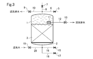
- FIG. 1 to 3 are schematic longitudinal sectional views of a packed tower to which the method of the present invention is applied.
- FIG. 1 shows a raw water passing process
- FIG. 2 shows a water draining process
- FIG. 3 shows a backwashing process.
- hydrogen-containing water is passed through the packed tower as raw water in a downward flow, and the hydrogen peroxide is decomposed with granular activated carbon in the tower.
- a support plate 2 capable of passing water is installed in a transverse manner in the lower part of the packed tower 1, and a packed bed 3 of granular activated carbon is formed on the upper side.
- the granular activated carbon those having an average particle size of 5 to 40 mesh, particularly 10 to 32 mesh are preferable, and coal-based activated carbon is particularly preferable.
- a raw water pipe 6 having a raw water inlet valve 5, an air pipe 8 having an air vent valve 7, and a backwash water outlet pipe 10 having a backwash water outlet valve 9 are provided at a fluid inlet / outlet portion at the top of the packed tower 1. It is connected.
- a strainer 11 is installed at a height h higher than the upper surface when the packed bed 3 is stationary, a drain pipe 12 is connected to the strainer 11, and the drain pipe 12 is connected to the drain pipe 12.
- a drain valve 13 is provided.
- the strainer 11 a mesh having an opening diameter smaller than the minimum particle diameter of granular activated carbon can be used.
- the above height h is 100 mm or more, preferably 100 to 500 mm, particularly preferably 200 to 300 mm.
- a treated water pipe 16 having a treated water outlet valve 15, a washing / drain outlet pipe 18 having a washing / drain outlet valve 17, and a reverse having a backwash water inlet valve 19 are provided in the fluid inlet / outlet portion at the bottom of the packed tower 1.
- a flush inlet pipe 20 is connected in the fluid inlet / outlet portion at the bottom of the packed tower 1.
- the backwash water inlet valve 19, the drain valve 13 and the backwash water outlet valve 9 are opened, the other valves are closed, and the backwash water is passed through the packed tower 1 in an upward flow. Water.
- the upward flow velocity at this time is set so that the granular activated carbon of the packed bed 3 does not flow out from the tower top.
- the LV is preferably about 15 to 30 m / h, particularly about 20 to 25 m / h.
- This primary back washing is preferably performed for about 10 to 30 seconds, particularly about 10 to 20 seconds. By this backwashing, the packed bed 3 is stirred and a part of the oxygen gas accumulated in the packed bed 3 is released.
- minute oxygen gas bubbles are associated and a part of them is detached.
- the backwash waste water is discharged from the drain pipe 12 and the backwash water outlet pipe 10. Thereafter, the flow of backwash water is stopped, or the LV is set to 5 m / h or less, particularly 2 m / h or less, and the packed bed 3 is stopped.
- This stationary step is preferably performed for 0.5 to 2 minutes, particularly 0.5 to 1 minute. During this static process, some of the associated bubbles that have accumulated in the packed bed 3 rise due to their buoyancy and are detached from the packed bed 3.
- backwash water is passed again in an upward flow and second backwash is performed. It is preferable that the LV and the duration of this second backwashing are within the preferable range of the first backwashing conditions.
- a cleaning process described later is performed.
- a second stationary process and a third backwashing may be performed, and a higher-order stationary process and You may perform a backwashing process.
- the water level in the tower 1 is lowered to the level of the drainage pipe 12 and backwash drainage is also discharged from the drainage pipe 12 with strainer during backwashing. Therefore, activated carbon does not flow out of the tower even if the flow rate of backwash water is increased. Moreover, in the backwash process, since the stationary process which sediments activated carbon is interposed between the upward circulation water processes, the outflow of activated carbon is also prevented by this. During this resting process, the associated bubbles are released by their own buoyancy. Therefore, it is possible to sufficiently perform backwashing and sufficiently release the gas. Further, there is no baffle or cross-shaped wire mesh in the upper part of the packed tower 1, so that maintenance in the packed tower and replacement of the packing material can be easily performed.
- the present invention is suitable for application to a packed tower in which hydrogen peroxide-containing water is passed through an activated carbon packed tower to decompose hydrogen peroxide.
- the present invention can also be applied to backwashing of various gas-dissolved water and filtration towers and catalyst packed towers in which a liquid that generates gas by reaction is passed as raw water.
- Example 1 In Example 1, the backwashing step after the draining step was performed only with backwashing (backwashing water flowing upward) for 10 minutes with the drainage valve 13 closed.
- the backwash LV is the same as in Example 1. Others were the same. As a result, it was confirmed that 0.05% of activated carbon flows out in one backwash.
Landscapes
- Chemical & Material Sciences (AREA)
- Organic Chemistry (AREA)
- Engineering & Computer Science (AREA)
- Chemical Kinetics & Catalysis (AREA)
- Environmental & Geological Engineering (AREA)
- Hydrology & Water Resources (AREA)
- Life Sciences & Earth Sciences (AREA)
- Water Supply & Treatment (AREA)
- Materials Engineering (AREA)
- Analytical Chemistry (AREA)
- Water Treatment By Sorption (AREA)
- Removal Of Specific Substances (AREA)
- Devices And Processes Conducted In The Presence Of Fluids And Solid Particles (AREA)
Abstract
Description
図1の通り、原水通水時には原水入口弁5と処理水出口弁15を開、その他の弁を閉とし、過酸化水素含有水よりなる原水を下向流にて充填層3に通水し、処理水を処理水管16から取り出す。過酸化水素含有水としては、過酸化水素含有量が100~500mg/L特に200~400mg/L程度のものが好適である。この通水を継続すると、充填層3内に次第に酸素ガスが溜ってくる。そして、チャンネリング現象により、過酸化水素が処理水中にリークするようになる。そこで、過酸化水素リークが検出されるか、又は所定時間通水を行った後、逆洗工程を行う。この逆洗工程に先立って水抜き工程を行う。
逆洗を行うには、まず図2のように、空気抜き弁7と水抜き弁13とを開、その他の弁を閉とし、充填塔1内の水位を水抜き管12のレベルまで低下させる。このように塔内の水位を低下させることにより、次工程の逆洗時に活性炭が塔頂部にまで達して流出することが防止される。
その後、図3の通り、逆洗水入口弁19、水抜き弁13及び逆洗水出口弁9を開、その他の弁を閉とし、充填塔1内に逆洗水を上向流にて通水する。このときの上向流速は、充填層3の粒状活性炭が塔頂から流出しない速度とする。具体的には、LVは15~30m/h特に20~25m/h程度が好適である。この第1次逆洗は、10~30sec特に10~20sec程度行うのが好ましい。この逆洗により、充填層3が攪拌され、充填層3内に溜っていた酸素ガスの一部が離脱する。また、微小な酸素ガス気泡が会合し、その一部が離脱する。逆洗排水は水抜き管12及び逆洗水出口管10から排出される。その後、逆洗水の通水を停止するか、又はLVを5m/h以下特に2m/h以下とし、充填層3を静止させる。この静止工程は、0.5~2min特に0.5~1min行うのが好ましい。この静止工程の間に、充填層3内に溜っていた会合気泡の一部がその浮力により上昇し、充填層3から離脱する。
上記の逆洗工程の後、原水入口弁5及び洗浄排水出口弁17を開、その他の弁を閉とし、原水を下向流にて通水し、充填層3を洗浄し、洗浄排水を洗浄排水出口管18から排出する。
図1の通り、塔径φ1000mm、塔高2000mmの塔内に静止層高1000mmの活性炭層3を充填した。h=200mmである。この充填塔1に対し原水(酸排水、過酸化水素濃度300mg/L)をSV=10hr-1で下向流にて24Hr通水した。処理水中の過酸化水素濃度は検出下限値以下(ND)であった。
第1次逆洗(LV=20m/h、10sec)
静止(1min)
第2次逆洗(LV=20m/h、10sec)
よりなる逆洗工程を行い、次いで原水をSV=10hr-1で15min通水する洗浄工程を行った。これにより、活性炭を全く流出させることなく過酸化水素含有水が処理された。
実施例1において、静止工程の代わりにLV=5m/hとなるように逆洗水を小流速にて上向流通水した。その他は同様とした。この実施例2によっても、活性炭を全く流出させることなく過酸化水素含有水が処理された。
実施例1おいて、上記水抜き工程後の逆洗工程を、水抜き弁13を閉とし、かつ10minの間の逆洗(逆洗水上向流通水)のみにて行った。逆洗LVは実施例1と同一である。その他は同様とした。その結果、1回の逆洗で0.05%の活性炭が流出することが認められた。
なお、本出願は、2011年12月5日付で出願された日本特許出願(特願2011-265815)に基づいており、その全体が引用により援用される。
Claims (4)
- 充填塔内の充填材にガス発生成分含有原水を下向流にて通水する充填塔を逆洗する方法において、
充填塔内の水位を低下させる水抜き工程を行った後、逆洗水を上向流にて通水して逆洗工程を行う充填塔の逆洗方法であって、
該逆洗工程において、逆洗水を通水した後、逆洗水の通水を停止するか又は逆洗水量を減少させて充填層を静止させ、次いで再度逆洗水を通水することを特徴とする充填塔の逆洗方法。 - 請求項1において、該充填塔内に、充填層の上面よりも100mm以上上位に、ストレーナを有した水抜き管を設けると共に該水抜き管に水抜き弁を設け、
該水抜き弁を開として前記水抜き工程及び逆洗工程を行うことを特徴とする充填塔の逆洗方法。 - 請求項1又は2において、前記原水は過酸化水素含有水であり、前記充填材は粒状活性炭であることを特徴とする充填塔の逆洗方法。
- 請求項3において、逆洗工程の最初の逆洗水上向流通水をLV15~30m/hで行い、通水停止又は減少時のLVを5m/h以下とし、その後の逆洗水通水のLVを20~25m/hとすることを特徴とする充填塔の逆洗方法。
Priority Applications (2)
| Application Number | Priority Date | Filing Date | Title |
|---|---|---|---|
| KR1020147013047A KR101994502B1 (ko) | 2011-12-05 | 2012-12-04 | 충전탑의 역세 방법 |
| JP2013548231A JP5971257B2 (ja) | 2011-12-05 | 2012-12-04 | 充填塔の逆洗方法 |
Applications Claiming Priority (2)
| Application Number | Priority Date | Filing Date | Title |
|---|---|---|---|
| JP2011-265815 | 2011-12-05 | ||
| JP2011265815 | 2011-12-05 |
Publications (1)
| Publication Number | Publication Date |
|---|---|
| WO2013084854A1 true WO2013084854A1 (ja) | 2013-06-13 |
Family
ID=48574221
Family Applications (1)
| Application Number | Title | Priority Date | Filing Date |
|---|---|---|---|
| PCT/JP2012/081315 Ceased WO2013084854A1 (ja) | 2011-12-05 | 2012-12-04 | 充填塔の逆洗方法 |
Country Status (3)
| Country | Link |
|---|---|
| JP (1) | JP5971257B2 (ja) |
| KR (1) | KR101994502B1 (ja) |
| WO (1) | WO2013084854A1 (ja) |
Cited By (3)
| Publication number | Priority date | Publication date | Assignee | Title |
|---|---|---|---|---|
| CN103601263A (zh) * | 2013-12-03 | 2014-02-26 | 宜兴市裕泰华环保有限公司 | 一种活性炭过滤器 |
| JP2014079665A (ja) * | 2012-10-12 | 2014-05-08 | Swing Corp | 水処理装置の洗浄方法 |
| WO2021182480A1 (ja) * | 2020-03-13 | 2021-09-16 | メタウォーター株式会社 | 水処理方法、水処理装置の制御装置、及び、水処理装置の制御プログラム |
Families Citing this family (1)
| Publication number | Priority date | Publication date | Assignee | Title |
|---|---|---|---|---|
| KR102352538B1 (ko) * | 2021-07-16 | 2022-01-20 | 효림산업주식회사 | 고도산화공정을 이용한 정수처리장치 및 이를 이용한 정수처리방법 |
Citations (7)
| Publication number | Priority date | Publication date | Assignee | Title |
|---|---|---|---|---|
| JPH03296404A (ja) * | 1990-04-13 | 1991-12-27 | Noritz Corp | 濾過槽の洗浄方法 |
| JPH0655008A (ja) * | 1992-08-07 | 1994-03-01 | Massey Kinzoku Kk | 濾過機における逆洗方法 |
| JPH07171561A (ja) * | 1993-12-21 | 1995-07-11 | Japan Organo Co Ltd | 粒状活性炭充填塔による過酸化水素の除去方法 |
| JPH08173957A (ja) * | 1994-12-20 | 1996-07-09 | Ebara Corp | 排水処理設備 |
| JPH10192844A (ja) * | 1997-01-13 | 1998-07-28 | Japan Organo Co Ltd | 活性炭処理方法およびその装置 |
| JP2004160432A (ja) * | 2002-08-09 | 2004-06-10 | Nippon Genryo Kk | 濾過装置 |
| WO2011001819A1 (ja) * | 2009-06-30 | 2011-01-06 | 株式会社ナガオカ | 水処理装置および水処理装置濾材層の洗浄方法 |
Family Cites Families (5)
| Publication number | Priority date | Publication date | Assignee | Title |
|---|---|---|---|---|
| JP3496280B2 (ja) * | 1994-07-12 | 2004-02-09 | 栗田工業株式会社 | 濾過装置 |
| JP3518060B2 (ja) | 1995-05-23 | 2004-04-12 | 栗田工業株式会社 | 濾過装置 |
| JP3147720B2 (ja) * | 1995-06-16 | 2001-03-19 | 栗田工業株式会社 | 下向流濾過装置の洗浄方法 |
| JP2000005511A (ja) | 1998-06-23 | 2000-01-11 | Matsushita Electric Ind Co Ltd | 濾過装置 |
| JP2009125657A (ja) | 2007-11-22 | 2009-06-11 | Kurita Water Ind Ltd | 濾過装置 |
-
2012
- 2012-12-04 KR KR1020147013047A patent/KR101994502B1/ko active Active
- 2012-12-04 WO PCT/JP2012/081315 patent/WO2013084854A1/ja not_active Ceased
- 2012-12-04 JP JP2013548231A patent/JP5971257B2/ja active Active
Patent Citations (7)
| Publication number | Priority date | Publication date | Assignee | Title |
|---|---|---|---|---|
| JPH03296404A (ja) * | 1990-04-13 | 1991-12-27 | Noritz Corp | 濾過槽の洗浄方法 |
| JPH0655008A (ja) * | 1992-08-07 | 1994-03-01 | Massey Kinzoku Kk | 濾過機における逆洗方法 |
| JPH07171561A (ja) * | 1993-12-21 | 1995-07-11 | Japan Organo Co Ltd | 粒状活性炭充填塔による過酸化水素の除去方法 |
| JPH08173957A (ja) * | 1994-12-20 | 1996-07-09 | Ebara Corp | 排水処理設備 |
| JPH10192844A (ja) * | 1997-01-13 | 1998-07-28 | Japan Organo Co Ltd | 活性炭処理方法およびその装置 |
| JP2004160432A (ja) * | 2002-08-09 | 2004-06-10 | Nippon Genryo Kk | 濾過装置 |
| WO2011001819A1 (ja) * | 2009-06-30 | 2011-01-06 | 株式会社ナガオカ | 水処理装置および水処理装置濾材層の洗浄方法 |
Cited By (5)
| Publication number | Priority date | Publication date | Assignee | Title |
|---|---|---|---|---|
| JP2014079665A (ja) * | 2012-10-12 | 2014-05-08 | Swing Corp | 水処理装置の洗浄方法 |
| CN103601263A (zh) * | 2013-12-03 | 2014-02-26 | 宜兴市裕泰华环保有限公司 | 一种活性炭过滤器 |
| WO2021182480A1 (ja) * | 2020-03-13 | 2021-09-16 | メタウォーター株式会社 | 水処理方法、水処理装置の制御装置、及び、水処理装置の制御プログラム |
| JPWO2021182480A1 (ja) * | 2020-03-13 | 2021-09-16 | ||
| JP7747617B2 (ja) | 2020-03-13 | 2025-10-01 | メタウォーター株式会社 | 水処理方法、水処理装置の制御装置、及び、水処理装置の制御プログラム |
Also Published As
| Publication number | Publication date |
|---|---|
| KR20140109365A (ko) | 2014-09-15 |
| JP5971257B2 (ja) | 2016-08-17 |
| KR101994502B1 (ko) | 2019-06-28 |
| JPWO2013084854A1 (ja) | 2015-04-27 |
Similar Documents
| Publication | Publication Date | Title |
|---|---|---|
| JP5971257B2 (ja) | 充填塔の逆洗方法 | |
| JP2011522698A (ja) | 残留オゾンを除去する上向流式オゾン接触槽 | |
| JP4814964B2 (ja) | 生物濾過処理用浮上濾材層の自動洗浄装置 | |
| JP4675830B2 (ja) | 水処理装置 | |
| JP2009161601A (ja) | 生物脱硫装置 | |
| JP5850063B2 (ja) | 濾過装置の逆洗方法 | |
| KR101689481B1 (ko) | 냉각탑의 냉각 순환수 수질개선을 위한 여과장치 및 이를 이용한 수처리시스템 | |
| JP5910635B2 (ja) | 過酸化水素含有水の処理方法 | |
| JP5209187B2 (ja) | 水処理方法および水処理装置 | |
| JP5894857B2 (ja) | 排水処理装置および排水処理方法 | |
| JP3095600B2 (ja) | 粒状活性炭充填塔による過酸化水素の除去方法 | |
| CN104606945A (zh) | 滤芯化学清洗装置及清洗方法 | |
| JP5807530B2 (ja) | 充填塔からの液抜き方法及び充填塔システム | |
| JPH0443705B2 (ja) | ||
| JP2016097370A (ja) | ろ過池の洗浄方法および水処理装置 | |
| JP2003320369A (ja) | 活性炭塔及び同塔における微細活性炭の漏出防止 | |
| JP2008093601A (ja) | 排水処理装置 | |
| JP5568434B2 (ja) | 混床式樹脂充填塔の混合樹脂の分離方法 | |
| JP4358174B2 (ja) | 嫌気性水処理装置 | |
| CN114212923B (zh) | 一种净水处理系统及方法 | |
| CN101301539A (zh) | 六阀吸附滤池工艺及设备 | |
| JP3377635B2 (ja) | 排水処理設備 | |
| CN211770451U (zh) | 一种污水残留去除装置 | |
| CN222524263U (zh) | 一种矿井水预处理装置 | |
| JP2001219009A (ja) | ろ材充填式ろ過装置 |
Legal Events
| Date | Code | Title | Description |
|---|---|---|---|
| 121 | Ep: the epo has been informed by wipo that ep was designated in this application |
Ref document number: 12855472 Country of ref document: EP Kind code of ref document: A1 |
|
| ENP | Entry into the national phase |
Ref document number: 2013548231 Country of ref document: JP Kind code of ref document: A |
|
| ENP | Entry into the national phase |
Ref document number: 20147013047 Country of ref document: KR Kind code of ref document: A |
|
| NENP | Non-entry into the national phase |
Ref country code: DE |
|
| 122 | Ep: pct application non-entry in european phase |
Ref document number: 12855472 Country of ref document: EP Kind code of ref document: A1 |