WO2013084660A1 - 燃料供給ユニット - Google Patents
燃料供給ユニット Download PDFInfo
- Publication number
- WO2013084660A1 WO2013084660A1 PCT/JP2012/079024 JP2012079024W WO2013084660A1 WO 2013084660 A1 WO2013084660 A1 WO 2013084660A1 JP 2012079024 W JP2012079024 W JP 2012079024W WO 2013084660 A1 WO2013084660 A1 WO 2013084660A1
- Authority
- WO
- WIPO (PCT)
- Prior art keywords
- fuel
- supply unit
- fuel supply
- strainer
- pump
- Prior art date
- Legal status (The legal status is an assumption and is not a legal conclusion. Google has not performed a legal analysis and makes no representation as to the accuracy of the status listed.)
- Ceased
Links
Images


Classifications
-
- F—MECHANICAL ENGINEERING; LIGHTING; HEATING; WEAPONS; BLASTING
- F02—COMBUSTION ENGINES; HOT-GAS OR COMBUSTION-PRODUCT ENGINE PLANTS
- F02M—SUPPLYING COMBUSTION ENGINES IN GENERAL WITH COMBUSTIBLE MIXTURES OR CONSTITUENTS THEREOF
- F02M37/00—Apparatus or systems for feeding liquid fuel from storage containers to carburettors or fuel-injection apparatus; Arrangements for purifying liquid fuel specially adapted for, or arranged on, internal-combustion engines
- F02M37/04—Feeding by means of driven pumps
- F02M37/08—Feeding by means of driven pumps electrically driven
- F02M37/10—Feeding by means of driven pumps electrically driven submerged in fuel, e.g. in reservoir
- F02M37/103—Mounting pumps on fuel tanks
-
- F—MECHANICAL ENGINEERING; LIGHTING; HEATING; WEAPONS; BLASTING
- F02—COMBUSTION ENGINES; HOT-GAS OR COMBUSTION-PRODUCT ENGINE PLANTS
- F02M—SUPPLYING COMBUSTION ENGINES IN GENERAL WITH COMBUSTIBLE MIXTURES OR CONSTITUENTS THEREOF
- F02M37/00—Apparatus or systems for feeding liquid fuel from storage containers to carburettors or fuel-injection apparatus; Arrangements for purifying liquid fuel specially adapted for, or arranged on, internal-combustion engines
- F02M37/20—Apparatus or systems for feeding liquid fuel from storage containers to carburettors or fuel-injection apparatus; Arrangements for purifying liquid fuel specially adapted for, or arranged on, internal-combustion engines characterised by means for preventing vapour lock
-
- F—MECHANICAL ENGINEERING; LIGHTING; HEATING; WEAPONS; BLASTING
- F02—COMBUSTION ENGINES; HOT-GAS OR COMBUSTION-PRODUCT ENGINE PLANTS
- F02M—SUPPLYING COMBUSTION ENGINES IN GENERAL WITH COMBUSTIBLE MIXTURES OR CONSTITUENTS THEREOF
- F02M37/00—Apparatus or systems for feeding liquid fuel from storage containers to carburettors or fuel-injection apparatus; Arrangements for purifying liquid fuel specially adapted for, or arranged on, internal-combustion engines
- F02M37/22—Arrangements for purifying liquid fuel specially adapted for, or arranged on, internal-combustion engines, e.g. arrangements in the feeding system
- F02M37/32—Arrangements for purifying liquid fuel specially adapted for, or arranged on, internal-combustion engines, e.g. arrangements in the feeding system characterised by filters or filter arrangements
- F02M37/50—Filters arranged in or on fuel tanks
Definitions
- the present invention relates to a fuel supply unit for supplying fuel from a fuel tank of a vehicle to an internal combustion engine.
- a fuel supply unit for supplying fuel from a fuel tank to a fuel injection device in a vehicle.
- a fuel supply unit for example, a housing, a fuel pump provided in the housing and capable of sucking and discharging fuel, and fuel vapor (bubbles) generated in the pump portion of the fuel pump are discharged to the outside.
- the vapor outlet is made of, for example, a porous material in which a nylon fiber mesh is formed in a bag shape, and a strainer for preventing the entry of foreign matters from the outside is mounted (for example, Japanese Patent Application Laid-Open No. 2008-274820). See the official gazette).
- the strainer removes the foreign matter together with the fuel from the vapor discharge port inside the housing. To prevent inhalation.
- the strainer is mounted at a position lower than the pump chamber of the fuel pump through which fuel is sucked. Therefore, for example, when fuel is supplied to the fuel tank when the fuel in the fuel tank is empty (the pump chamber is also empty), both the suction port and the vapor discharge port communicating with the pump chamber are provided. Since the fuel pump is opened downward at the lower part of the fuel pump, the fuel level in the fuel tank rises in a state where the gas does not flow into the pump chamber and the gas remains. At this time, the strainer formed in a mesh shape from the porous material is immersed in the fuel, so that the fuel enters into a plurality of holes, the holes are blocked by the surface tension, and the gas does not easily pass through. Become.
- a fuel pump In general, a fuel pump is designed to exhibit predetermined suction capacity and discharge capacity when fuel is supplied to the pump chamber, and in a state where there is no fuel in the pump chamber (empty state). The suction ability and the discharge ability are reduced. Therefore, if there is no fuel in the pump chamber and the strainer at the vapor outlet is immersed in the fuel, even if the impeller of the pump section starts to rotate and starts to suck in the fuel, the gas in the pump chamber On the other hand, the pressure sufficient to overcome the surface tension of the fuel filled in the hole of the strainer cannot be applied.
- the gas in the pump chamber cannot be discharged to the outside, and accordingly the fuel cannot be sucked from the suction port, so that the fuel pump is idling.
- a general object of the present invention is to provide a fuel supply unit capable of reliably sucking in the fuel by preventing the fuel pump from idling even when the fuel in the fuel tank runs out.
- the present invention includes a base member that is attached to and closed at an opening of a fuel tank, a fuel pump that is held by a holder connected to the base member, and that sucks and discharges fuel, and is formed in the fuel pump and in the fuel.
- a fuel supply unit having a discharge hole for discharging the generated vapor and a strainer for preventing foreign matter from entering through the discharge hole
- the strainer has a filter having an outer peripheral surface formed in a mesh shape, and a communication port having a size that does not form a liquid film due to the surface tension of the fuel, and communicates with the filtration region of the foreign matter in the filter.
- the fuel tank has a space not filled with the fuel when the fuel is full, and the communication port opens into the space.
- the fuel pump in the fuel supply unit, is provided with a strainer that discharges vapor generated in the fuel, and is provided with a strainer that can prevent foreign matter from entering through the discharge hole.
- a filter having an outer peripheral surface formed in a mesh shape, a communication port having a size that does not form a liquid film due to the surface tension of the fuel, and communicating with the filtration region of the foreign matter in the filter.
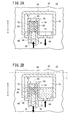
- FIG. 2A is an enlarged view showing the vicinity of the strainer in the fuel supply unit of FIG. 1
- FIG. 2B is an enlarged view of the vicinity of the strainer showing a state in which the suction filter is clogged in the fuel supply unit of FIG. 2A.
- the fuel supply unit 10 includes a base member 14 fixed to the upper surface 12a of the fuel tank 12, a bottomed cylindrical holder 16 connected to the base member 14, and the holder 16 And a strainer 20 connected to the holder 16 and preventing entry of foreign matter or the like from the fuel tank 12 side.
- the fuel supply unit 10 is an upper type used for the fuel tank 12 having an opening 22 at the top.
- the base member 14 is attached to an opening 22 opened on the upper surface 12 a of the fuel tank 12, a disc-shaped main body 24 covering the opening 22, and an upright position with respect to the main body 24. And a connecting portion 26 to be inserted.
- the connecting portion 26 is inserted from the outside to the inside of the fuel tank 12, and the outer edge of the main body 24 is covered with the upper surface 12 a of the fuel tank 12 with the opening 22 covered with the main body 24.
- it is fixed with a plurality of bolts 28.
- the base member 14 is provided with a connection connector 30 that is electrically connected to the fuel pump 18 and that receives a control signal from a controller (not shown).
- the holder 16 is formed in a bottomed cylindrical shape and has a suction side holder 34 having a suction port 32 for sucking fuel in the fuel tank 12.
- the holder 16 is mounted inside the suction side holder 34, and the connection portion 26 of the base member 14. And a discharge-side holder 36 connected thereto.
- An intake filter (not shown) that prevents entry into the fuel pump 18 by capturing foreign matter or the like contained in the fuel is attached to the intake port 32.
- the discharge side holder 36 is formed with a discharge port (not shown) for discharging the fuel sucked by the fuel pump 18 to the outside.
- the suction side holder 34 is connected to a vapor discharge hole (discharge hole) 40 communicating with the pump chamber 38 of the fuel pump 18, and a vapor discharge passage through which vapor (bubbles) in the fuel is discharged through the vapor discharge hole 40. (Discharge passage) 42 is provided.
- One end of the vapor discharge passage 42 is formed in the lower portion of the suction side holder 34, and extends downward in the vertical direction (arrow A direction), and the lower end of the first passage portion 44.
- a second passage portion 46 that extends in a horizontal direction perpendicular to the axis of the suction side holder 34 and is connected to the end of the second passage portion 46 so as to be substantially perpendicular to the outer periphery of the discharge side holder 36. It consists of the 3rd channel
- the third passage portion 48 of the vapor discharge passage 42 has an end portion extending substantially to the vicinity of the center along the axial direction of the holder 16 and opening upward (in the direction of arrow B).
- a strainer 20 for preventing inhalation of foreign matters contained in the fuel in the fuel tank 12 is mounted, and the strainer 20 is formed on the outer peripheral surface of the discharge side holder 36. It is stored inside the storage section (enclosure wall) 50.
- the storage part 50 is formed so as to protrude radially outward with respect to the outer peripheral surface of the discharge-side holder 36 and open in a rectangular cross section downward (in the direction of arrow A), and a space 52 is formed therein. It is formed.
- the storage portion 50 includes an upper wall 54 extending in a direction orthogonal to the axis of the discharge side holder 36, and an end portion of the upper wall 54. It consists of an outer wall 56 that extends perpendicularly downward.
- the strainer 20 includes, for example, a porous body (filter) 58 formed in a cylindrical shape from a mesh-like resin material, and a housing 60 that holds the porous body 58.
- the outer peripheral surface of the porous body 58 is formed in a mesh shape. For example, when the fuel passes in a radial direction with respect to the porous body 58, foreign matters contained in the fuel are captured, and the foreign matters are discharged into the vapor. Inhalation into the fuel pump 18 through the passage 42 is prevented. That is, the outer peripheral surface of the porous body 58 functions as a filtration region that can capture and filter foreign matters and the like.
- the housing 60 includes a cylindrical holding portion 62 that holds the porous body 58, and a partition wall 64 that is formed at the lower end portion of the holding portion 62 and closes the storage portion 50, and is provided at the lower end portion of the holding portion 62.
- the end of the vapor discharge passage 42 is connected, and the porous body 58 and the vapor discharge passage 42 are arranged coaxially.
- a communication port 66 penetrating in the axial direction (arrow A, B direction) of the holding unit 62 is formed at the upper end of the holding unit 62, and the inside and outside of the holding unit 62 communicate with each other through the communication port 66.
- the porous body 58 is exposed to the outside through the communication port 66.
- the communication port 66 is formed coaxially with the porous body 58.
- the communication port 66 is opened, for example, in a circular shape in cross section, and the diameter thereof is set to such a size that a liquid film is not formed by the surface tension when the fuel adheres. Specifically, it is set larger than the pore diameter of the porous body 58.
- a plurality of window portions 70 penetrating in the radial direction are opened in the side portion of the holding portion 62, and the window portions 70 are spaced apart from each other at equal intervals along the circumferential direction of the holding portion 62. .
- the inside and the outside of the holding part 62 communicate with each other through the window part 70, and the porous body 58 is exposed to the outside through the window part 70.
- the partition wall 64 extends in a direction orthogonal to the axis of the holding portion 62, and its outer edge is bent upward at a substantially right angle and comes into contact with the inner wall surface of the storage portion 50.
- the space 52 is closed.
- the partition wall 64 is formed with a hole 72 that penetrates the partition wall 64, and the space 52 of the storage unit 50 and the inside of the fuel tank 12 communicate with each other through the hole 72.
- the housing 60 is arranged so that the partition wall 64 is located near the lower end of the outer wall 56 of the storage unit 50 when the housing 60 is mounted on the storage unit 50 while holding the porous body 58.
- the fuel pump 18 includes an electric motor 74 that is driven to rotate based on a control signal from a controller (not shown), and a pump unit 76 that sucks and discharges fuel under the rotating action of the electric motor 74.
- the impeller 80 connected to the drive shaft 78 of the electric motor 74 and the pump chamber 38 into which fuel is sucked when the impeller 80 rotates.
- the pump chamber 38 communicates with the suction port 32 and the vapor discharge hole 40 extending downward (in the direction of arrow A), and the vapor generated in the pump section 76 is transferred from the pump chamber 38 to the vapor discharge hole 40. It is discharged and discharged to the outside through a vapor discharge passage 42 connected below the vapor discharge hole 40.
- the fuel supply unit 10 according to the first embodiment of the present invention is basically configured as described above. Next, the operation, operation, and effect thereof will be described.
- a control signal from a controller is input through the connection connector 30, and the impeller 80 of the fuel pump 18 is rotated by driving the electric motor 74 based on the control signal. Then, after the fuel in the fuel tank 12 is sucked into the pump chamber 38 through the suction port 32, it is discharged to a discharge port (not shown).
- the vapor generated when the fuel pump 18 is driven to rotate is discharged from the pump chamber 38 to the vapor discharge passage 42 through the vapor discharge hole 40, and sequentially moves to the first to third passage portions 44, 46, and 48. After that, it passes through the strainer 20 and is discharged into the fuel tank 12 through the space 52 and the hole 72.
- the fuel in the fuel tank 12 is exhausted, and the fuel is also exhausted from the pump chamber 38 of the fuel supply unit 10 (empty state) to the fuel tank 12. A case where fuel is supplied will be described.
- the fuel when fuel is supplied to the fuel tank 12, the fuel is gradually filled upward (in the direction of arrow B) from the bottom wall side while raising the liquid level in the fuel tank 12. Further, the fuel flows from the suction port 32 into the pump chamber 38 and gradually fills the pump chamber 38.
- the gas remaining in the pump chamber 38 is pressed by the fuel and discharged from the pump chamber 38 to the vapor discharge passage 42 through the vapor discharge hole 40, and from the end to the inside of the porous body 58 in the strainer 20. And circulate. At this time, the outer peripheral surface of the porous body 58 formed in a mesh shape is blocked by the surface tension of the already attached fuel, and it is difficult for the gas to pass therethrough, but as shown in FIG. 2A.
- the gas is discharged to the outside of the strainer 20 by flowing to the communication port 66 through the upper part of the porous body 58 that is not formed in a mesh shape.
- the diameter of the communication port 66 is set to such a size that a liquid film is not formed by surface tension when the fuel adheres, so that the communication port 66 may be blocked by the fuel. Absent.
- the gas flows from the lower end portion of the porous body 58 facing the vapor discharge passage 42 upward (in the direction of arrow B) along the axial direction, and then flows from the upper end portion to the communication port 66.
- the gas is discharged into the fuel tank 12 through the hole 72 from the storage portion 50 which is outside the strainer 20.
- the fuel gradually begins to flow into the pump chamber 38, and at the same time, the gas in the pump chamber 38 is suitably discharged to the fuel tank 12 through the vapor discharge passage 42 and the strainer 20. Therefore, the fuel pump 18 can be operated in a state where the pump chamber 38 is filled with fuel, and the fuel can be reliably sucked by the fuel pump 18. Then, the fuel sucked by the fuel pump 18 is supplied to a fuel injection device of an internal combustion engine (not shown) through a discharge port (not shown).
- the liquid level L of the fuel in the fuel tank 12 is stored in the storage portion 50 as shown in FIG. 2B.
- the space 52 is higher than the upper end of the space 52, the fuel flows into the storage portion 50 through the hole 72, and may flow from the vapor discharge passage 42 toward the fuel pump 18 through the strainer 20.
- the fuel passes through the hole 72 of the housing 60 from the outer peripheral surface of the porous body 58 to the inside and then flows into the vapor discharge passage 42.
- Foreign matter contained therein is formed in a mesh shape and is reliably captured by the porous body 58 via the outer peripheral surface which is a filtration region.
- the fuel flows into the porous body 58 from the outer peripheral surface side of the porous body 58 through the opening 22 of the housing 60 in the storage portion 50, so that the liquid level of the fuel is the upper end of the porous body 58.
- the fuel is reliably prevented from flowing from the upper part of the porous body 58 into the porous body 58 through the communication port 66, and the foreign matter in the fuel is not removed by the strainer 20 and the fuel pump 18 is removed. It is possible to prevent the entry to the side.
- the strainer 20 is provided at the upper end portion of the vapor discharge passage 42 for discharging the vapor, and the porous body 58 faces the upper end of the housing 60 constituting the strainer 20.
- the communication port 66 that communicates the inside and the outside of the housing 60, the fuel tank 12 and the fuel in the pump chamber 38 are completely removed from the fuel tank 12 or when the fuel is supplied to the fuel tank 12, or in a mesh shape. Even when the outer peripheral surface of the formed porous body 58 is blocked by the adhesion of fuel, the porous body 58 can be circulated along the axial direction of the porous body 58 and discharged from the communication port 66 to the outside.
- the state in which no fuel is supplied to the pump chamber 38 and the state in which the strainer 20 is immersed in the fuel do not occur at the same time, and the gas remaining in the pump chamber 38 through the strainer 20 is reliably discharged to the outside. Can be discharged.
- the idling of the fuel pump 18 that occurs when no fuel remains in the pump chamber 38 can be reliably prevented, and the inhalation of the fuel by preventing the fuel pump 18 from sucking in the fuel can be reliably performed. can do.
- the communication port 66 formed in the strainer 20 is arranged at a position that opens to the space 52 in which the storage unit 50 is not filled with the fuel even when the fuel tank 12 is completely filled with fuel. Therefore, the fuel from which foreign matters and the like have not been removed is prevented from entering the fuel pump 18 through the communication port 66.
- the storage portion 50 is provided so as to surround the upper side and the side of the strainer 20 and has a space 52 therein, the space 52 in which no fuel is filled below the fuel level in the fuel tank 12. Can be provided. Therefore, since the space 52 can be arranged at a desired position without considering the fuel level in the fuel tank 12, the degree of design freedom can be increased.
- the suction filter is clogged, and the fuel level becomes lower than the space 52 from the vapor discharge hole 40. Start inhaling gas.
- the intake filter may be clogged based on the uncomfortable feeling generated in the internal combustion engine. It can also be used as a clogging detection means.
- the storage portion 50 is closed by the partition wall 64 of the housing 60 constituting the strainer 20, and the storage portion 50 and the fuel tank 12 are communicated only through the hole 72, thereby generating the fuel generated in the fuel tank 12. It is possible to prevent the flow, vibration, etc. of the gas from being transmitted to the fuel in the storage unit 50.
- the vapor discharge passage 42 in the suction side holder 34 constituting the holder 16 the vapor discharge hole 40 and the vapor discharge passage of the fuel pump 18 can be simply mounted on the holder 16. Therefore, it is possible to improve the assemblability of the fuel supply unit 10.
- the present invention is not limited to this configuration.
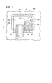
- a strainer 110 that abuts on the partition wall 104 of the housing 102 and has a porous body 108 disposed coaxially with the hole 106 of the partition wall 104 is provided.
- the end of the vapor discharge passage 112 may be connected in parallel with the porous body 108 offset by a predetermined distance.
- the end portion of the vapor discharge passage 112 is inserted so as to penetrate the partition wall 104, and the porous body 108 is disposed via a holding portion 114 provided coaxially with the hole portion 106. .
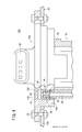
- a fuel supply unit 150 according to the second embodiment is shown in FIG.
- the same referential mark is attached
- the storage unit 152 that covers the strainer 20 is provided in the lower part of the base member 154. This is different from the fuel supply unit 10 according to FIG.
- the base member 154 includes a storage portion 152 that protrudes radially outward with respect to the outer peripheral surface and opens downward (in the direction of arrow A).
- the storage portion 152 is formed so as to face the other end portion of the vapor discharge passage 42 formed in the suction side holder 34, and an upper wall 156 facing the upper side of the strainer 20 attached to the vapor discharge passage 42, And an outer wall 158 extending downward from the end of the wall 54.
- the height of the outer wall 158 is formed at a predetermined height from the end surface of the upper wall 156 downward so as to cover the entire strainer 20.
- the storage portion 152 in the base member 154, for example, compared with the case where the storage portion 50 is formed in the holder 16, it can be easily formed, By assembling the holder 16 holding the fuel pump 18 to the base member 154, the strainer 20 can be reliably and easily disposed in the storage portion 152. As a result, the configuration of the fuel supply unit 150 can be simplified and the number of assembling steps can be reduced.
- a fuel supply unit 170 according to a third embodiment is shown in FIG.
- the same referential mark is attached
- the fuel supply unit 170 is a subordinate type used in a fuel tank 174 having an opening 172 in the bottom wall 174 a and is connected to the base member 176.
- the portion 178 functions as a part of the holder 180 capable of holding the fuel pump 188, and the storage portion 184 that covers the strainer 20 is provided in the discharge side holder 182 of the holder 180. This is different from the fuel supply units 10 and 150 according to the embodiment.
- the base member 176 is attached to an opening 172 that opens in the bottom wall 174a of the fuel tank 174, and has a disc-shaped main body 186 that covers the opening 172, and the opening 172 that stands upright with respect to the main body 186. 172 and a connecting portion 178 to be inserted into 172. Then, the connecting portion 178 is inserted from the outside to the inside of the fuel tank 174, and the holder 180 is coupled.
- the base member 176 is fixed to the bottom wall of the fuel tank 174 with a plurality of bolts 28 with the outer edge of the main body 186 covered with the main body 186.
- a fuel pump 188 is accommodated in the center of the connection portion 178, and a suction port 190 through which fuel is sucked adjacent to the connection portion 178 and a vapor discharge passage 192 extending substantially parallel to the fuel pump 188. It is formed.
- a strainer 20 is attached to the upper end of the vapor discharge passage 192 that is open.
- the holder 180 is provided so as to cover the connection part 178 and the upper part of the fuel pump 188 accommodated in the connection part 178, and the storage part 184 provided on the outer peripheral side and opened downward is formed so as to cover the strainer 20. Is done.
- the storage portion 184 includes an upper wall 194 that faces the upper portion of the strainer 20 and an outer wall 196 that extends downward from the end of the upper wall 194.
- the strainer 20 has an upper portion covered with an upper wall 194 and an outer peripheral surface covered with an outer wall 196.
- a suction filter 202 is connected to the suction port 190 with respect to the tube 200 connected to the suction connection portion 198 of the fuel pump 188, and foreign matter contained in the fuel sucked into the suction connection portion 198 is captured. .
- the strainer 20 is provided at the upper end portion of the vapor discharge passage 192 for discharging the vapor, and the porous body 58 faces the upper end of the housing 60 constituting the strainer 20, and the housing
- the communication port 66 that communicates the inside and the outside of the fuel tank 60
- the network formed in the mesh shape is formed. Even when the outer peripheral surface of the porous body 58 is blocked by the adhesion of fuel, it can be circulated along the axial direction of the porous body 58 and discharged from the communication port 66 to the outside.
- the state in which no fuel is supplied to the pump chamber 38 and the state in which the strainer 20 is immersed in the fuel do not occur at the same time, and the gas remaining in the pump chamber 38 through the strainer 20 is reliably discharged to the outside. Can be discharged.
- the fuel supply unit according to the present invention is not limited to the above-described embodiment, and various configurations can be adopted without departing from the gist of the present invention.
Landscapes
- Engineering & Computer Science (AREA)
- Chemical & Material Sciences (AREA)
- Combustion & Propulsion (AREA)
- Mechanical Engineering (AREA)
- General Engineering & Computer Science (AREA)
- Cooling, Air Intake And Gas Exhaust, And Fuel Tank Arrangements In Propulsion Units (AREA)
- Filtration Of Liquid (AREA)
- Structures Of Non-Positive Displacement Pumps (AREA)
- Wick-Type Burners And Burners With Porous Materials (AREA)
Abstract
Description
前記ストレーナには、外周面が網目状に形成されたフィルタと、前記燃料の表面張力による液膜が形成されない大きさを有し、且つ、前記フィルタにおける前記異物の濾過領域を連通する連通口を備えると共に、前記燃料タンクには、前記燃料の満量時において該燃料で満たされない空間を有し、前記連通口が前記空間に開口することを特徴とする。
Claims (8)
- 燃料タンク(12、174)の開口部に装着され閉塞するベース部材(14、154、176)と、該ベース部材(14、154、176)に接続されるホルダ(16、180)に保持され、燃料を吸入・吐出する燃料ポンプ(18、188)と、前記燃料ポンプ(18、188)に形成され前記燃料中で生じたベーパを排出する排出孔(40)と、前記排出孔(40)を通じた異物の進入を防止するストレーナ(20、110)とを有する燃料供給ユニット(10、100、150、170)において、
前記ストレーナ(20、110)には、外周面が網目状に形成されたフィルタ(58)と、前記燃料の表面張力による液膜が形成されない大きさを有し、且つ、前記フィルタ(58)における前記異物の濾過領域を連通する連通口(66)を備えると共に、前記燃料タンク(12、174)には、前記燃料の満量時において該燃料で満たされない空間(52)を有し、前記連通口(66)が前記空間(52)に開口することを特徴とする燃料供給ユニット。 - 請求項1記載の燃料供給ユニットにおいて、
前記空間(52)は、少なくとも前記ストレーナ(20)の上方及び側方を覆う包囲壁(50、158)によって形成されることを特徴とする燃料供給ユニット。 - 請求項2記載の燃料供給ユニットにおいて、
前記包囲壁(50)は、前記ホルダ(16)に形成されることを特徴とする燃料供給ユニット。 - 請求項2記載の燃料供給ユニットにおいて、
前記包囲壁(158)は、前記ベース部材(154)に形成されることを特徴とする燃料供給ユニット。 - 請求項1記載の燃料供給ユニットにおいて、
前記空間(52)の下方には、前記燃料タンク(12)の間に設けられる流路の流路断面積を減少させる仕切壁(104)が設けられることを特徴とする燃料供給ユニット。 - 請求項5記載の燃料供給ユニットにおいて、
前記仕切壁(104)は、前記ストレーナ(110)と一体で形成されることを特徴とする燃料供給ユニット。 - 請求項1~6のいずれか1項に記載の燃料供給ユニットにおいて、
前記ホルダ(16)には、前記排出孔(40)と前記ストレーナ(20、110)とを連通させる排出通路(42)が形成され、前記ホルダ(16)と前記燃料ポンプ(18)との組み付け時に前記排出通路(42)と前記排出孔(40)とが接続されて連通することを特徴とする燃料供給ユニット。 - 請求項1~7のいずれか1項に記載の燃料供給ユニットにおいて、
前記連通口(66)は、前記フィルタ(58)の孔径より大きな孔径で開口して形成されることを特徴とする燃料供給ユニット。
Priority Applications (4)
| Application Number | Priority Date | Filing Date | Title |
|---|---|---|---|
| BR112014013408-1A BR112014013408B1 (pt) | 2011-12-05 | 2012-11-08 | Unidade de fornecimento de combustível |
| CN201280059734.6A CN103987951B (zh) | 2011-12-05 | 2012-11-08 | 燃料供给单元 |
| DE112012005061.4T DE112012005061B4 (de) | 2011-12-05 | 2012-11-08 | Kraftstoffzufuhreinheit |
| IN4170CHN2014 IN2014CN04170A (ja) | 2011-12-05 | 2014-06-04 |
Applications Claiming Priority (2)
| Application Number | Priority Date | Filing Date | Title |
|---|---|---|---|
| JP2011-265470 | 2011-12-05 | ||
| JP2011265470A JP5809948B2 (ja) | 2011-12-05 | 2011-12-05 | 燃料供給ユニット |
Publications (1)
| Publication Number | Publication Date |
|---|---|
| WO2013084660A1 true WO2013084660A1 (ja) | 2013-06-13 |
Family
ID=48574039
Family Applications (1)
| Application Number | Title | Priority Date | Filing Date |
|---|---|---|---|
| PCT/JP2012/079024 Ceased WO2013084660A1 (ja) | 2011-12-05 | 2012-11-08 | 燃料供給ユニット |
Country Status (6)
| Country | Link |
|---|---|
| JP (1) | JP5809948B2 (ja) |
| CN (1) | CN103987951B (ja) |
| BR (1) | BR112014013408B1 (ja) |
| DE (1) | DE112012005061B4 (ja) |
| IN (1) | IN2014CN04170A (ja) |
| WO (1) | WO2013084660A1 (ja) |
Cited By (1)
| Publication number | Priority date | Publication date | Assignee | Title |
|---|---|---|---|---|
| WO2016030041A1 (en) * | 2014-08-27 | 2016-03-03 | Delphi International Operations Luxembourg S.À R.L. | High pressure fuel pump with a delivery valve having a porous member |
Families Citing this family (4)
| Publication number | Priority date | Publication date | Assignee | Title |
|---|---|---|---|---|
| JP6065319B2 (ja) * | 2013-03-29 | 2017-01-25 | 株式会社ケーヒン | 燃料供給装置 |
| DE102014225309A1 (de) * | 2014-12-09 | 2016-06-09 | Robert Bosch Gmbh | Kraftstoffpumpenanordnung |
| JP6487750B2 (ja) * | 2015-03-31 | 2019-03-20 | 株式会社ケーヒン | 燃料供給装置 |
| DE112017000895B4 (de) * | 2016-02-19 | 2022-03-10 | Aisan Kogyo Kabushiki Kaisha | Kraftstoffzufuhrvorrichtung mit Siebbauteil |
Citations (5)
| Publication number | Priority date | Publication date | Assignee | Title |
|---|---|---|---|---|
| JPS5731934Y2 (ja) * | 1977-05-06 | 1982-07-14 | ||
| JPS6153562U (ja) * | 1984-09-11 | 1986-04-10 | ||
| JPS63141611U (ja) * | 1987-03-09 | 1988-09-19 | ||
| JPH04132871A (ja) * | 1990-09-21 | 1992-05-07 | Mitsubishi Electric Corp | 円周流式液体ポンプ |
| JPH0469692U (ja) * | 1990-10-24 | 1992-06-19 |
Family Cites Families (8)
| Publication number | Priority date | Publication date | Assignee | Title |
|---|---|---|---|---|
| US4844621A (en) | 1985-08-10 | 1989-07-04 | Nippondenso Co., Ltd. | Fuel pump with passage for attenuating noise generated by impeller |
| JP2005226524A (ja) * | 2004-02-12 | 2005-08-25 | Denso Corp | 燃料供給装置 |
| US7182869B2 (en) | 2004-10-07 | 2007-02-27 | Ti Group Automotive Systems, L.L.C. | Fuel filter arrangement |
| US20080107549A1 (en) * | 2006-11-08 | 2008-05-08 | Ti Group Automotive Systems, L.L.C. | Fuel pump and filter assembly |
| JP2008274820A (ja) | 2007-04-27 | 2008-11-13 | Aisan Ind Co Ltd | 燃料ポンプ及び燃料ポンプ装置 |
| JP2009236006A (ja) * | 2008-03-27 | 2009-10-15 | Mitsubishi Electric Corp | 燃料供給装置 |
| JP2010090830A (ja) * | 2008-10-09 | 2010-04-22 | Mitsubishi Electric Corp | 車両用燃料供給装置 |
| JP2011153599A (ja) * | 2010-01-28 | 2011-08-11 | Denso Corp | 燃料供給装置 |
-
2011
- 2011-12-05 JP JP2011265470A patent/JP5809948B2/ja active Active
-
2012
- 2012-11-08 BR BR112014013408-1A patent/BR112014013408B1/pt active IP Right Grant
- 2012-11-08 WO PCT/JP2012/079024 patent/WO2013084660A1/ja not_active Ceased
- 2012-11-08 CN CN201280059734.6A patent/CN103987951B/zh active Active
- 2012-11-08 DE DE112012005061.4T patent/DE112012005061B4/de active Active
-
2014
- 2014-06-04 IN IN4170CHN2014 patent/IN2014CN04170A/en unknown
Patent Citations (5)
| Publication number | Priority date | Publication date | Assignee | Title |
|---|---|---|---|---|
| JPS5731934Y2 (ja) * | 1977-05-06 | 1982-07-14 | ||
| JPS6153562U (ja) * | 1984-09-11 | 1986-04-10 | ||
| JPS63141611U (ja) * | 1987-03-09 | 1988-09-19 | ||
| JPH04132871A (ja) * | 1990-09-21 | 1992-05-07 | Mitsubishi Electric Corp | 円周流式液体ポンプ |
| JPH0469692U (ja) * | 1990-10-24 | 1992-06-19 |
Cited By (2)
| Publication number | Priority date | Publication date | Assignee | Title |
|---|---|---|---|---|
| WO2016030041A1 (en) * | 2014-08-27 | 2016-03-03 | Delphi International Operations Luxembourg S.À R.L. | High pressure fuel pump with a delivery valve having a porous member |
| GB2544426A (en) * | 2014-08-27 | 2017-05-17 | Delphi Int Operations Luxembourg Sarl | High pressure fuel pump with a delivery valve having a porous member |
Also Published As
| Publication number | Publication date |
|---|---|
| BR112014013408A2 (pt) | 2017-06-13 |
| CN103987951A (zh) | 2014-08-13 |
| IN2014CN04170A (ja) | 2015-07-17 |
| JP5809948B2 (ja) | 2015-11-11 |
| DE112012005061T5 (de) | 2014-08-28 |
| BR112014013408B1 (pt) | 2021-09-28 |
| DE112012005061T8 (de) | 2014-09-11 |
| JP2013117198A (ja) | 2013-06-13 |
| DE112012005061B4 (de) | 2018-03-22 |
| CN103987951B (zh) | 2016-03-09 |
Similar Documents
| Publication | Publication Date | Title |
|---|---|---|
| JP5809948B2 (ja) | 燃料供給ユニット | |
| JPWO2018030373A1 (ja) | 駆動装置 | |
| US8915233B2 (en) | Fuel supply equipment | |
| JP5663624B2 (ja) | 燃料供給装置 | |
| JP2007224748A (ja) | サクションフィルタおよびそれを用いた燃料供給装置 | |
| JP5709220B2 (ja) | 燃料供給装置 | |
| JP2007536467A (ja) | 自動車用の燃料供給装置 | |
| JP5855439B2 (ja) | 燃料供給ユニット | |
| KR101476052B1 (ko) | 연료 공급 장치 | |
| JP2009257308A (ja) | ポンプモジュール | |
| JP6487750B2 (ja) | 燃料供給装置 | |
| JP6716003B1 (ja) | 燃料供給装置 | |
| JP6020917B2 (ja) | 燃料供給装置 | |
| JP2010090830A (ja) | 車両用燃料供給装置 | |
| JP2004218567A (ja) | 燃料供給装置 | |
| JP6065319B2 (ja) | 燃料供給装置 | |
| JP7202826B2 (ja) | 燃料供給装置 | |
| TWI693338B (zh) | 燃料供應裝置 | |
| JP2001082276A (ja) | 燃料供給装置 | |
| JP2013064329A (ja) | 燃料供給装置 | |
| JP2009216011A (ja) | サクションフィルタ | |
| JP2008002407A (ja) | モータポンプ装置 | |
| WO2024135311A1 (ja) | 燃料供給装置 | |
| JP6174913B2 (ja) | ポンプユニット | |
| JP2012188940A (ja) | 燃料供給ユニット |
Legal Events
| Date | Code | Title | Description |
|---|---|---|---|
| WWE | Wipo information: entry into national phase |
Ref document number: 201280059734.6 Country of ref document: CN |
|
| 121 | Ep: the epo has been informed by wipo that ep was designated in this application |
Ref document number: 12854731 Country of ref document: EP Kind code of ref document: A1 |
|
| WWE | Wipo information: entry into national phase |
Ref document number: IDP00201403254 Country of ref document: ID |
|
| WWE | Wipo information: entry into national phase |
Ref document number: 1120120050614 Country of ref document: DE Ref document number: 112012005061 Country of ref document: DE |
|
| REG | Reference to national code |
Ref country code: BR Ref legal event code: B01A Ref document number: 112014013408 Country of ref document: BR |
|
| 122 | Ep: pct application non-entry in european phase |
Ref document number: 12854731 Country of ref document: EP Kind code of ref document: A1 |
|
| ENP | Entry into the national phase |
Ref document number: 112014013408 Country of ref document: BR Kind code of ref document: A2 Effective date: 20140603 |
|
| WWG | Wipo information: grant in national office |
Ref document number: 201948034861 Country of ref document: IN |