WO2013084584A1 - 冷蔵庫 - Google Patents
冷蔵庫 Download PDFInfo
- Publication number
- WO2013084584A1 WO2013084584A1 PCT/JP2012/075985 JP2012075985W WO2013084584A1 WO 2013084584 A1 WO2013084584 A1 WO 2013084584A1 JP 2012075985 W JP2012075985 W JP 2012075985W WO 2013084584 A1 WO2013084584 A1 WO 2013084584A1
- Authority
- WO
- WIPO (PCT)
- Prior art keywords
- heat insulation
- side wall
- heat insulating
- insulation panel
- cabinet
- Prior art date
- Legal status (The legal status is an assumption and is not a legal conclusion. Google has not performed a legal analysis and makes no representation as to the accuracy of the status listed.)
- Ceased
Links
Images


Classifications
-
- F—MECHANICAL ENGINEERING; LIGHTING; HEATING; WEAPONS; BLASTING
- F25—REFRIGERATION OR COOLING; COMBINED HEATING AND REFRIGERATION SYSTEMS; HEAT PUMP SYSTEMS; MANUFACTURE OR STORAGE OF ICE; LIQUEFACTION SOLIDIFICATION OF GASES
- F25D—REFRIGERATORS; COLD ROOMS; ICE-BOXES; COOLING OR FREEZING APPARATUS NOT OTHERWISE PROVIDED FOR
- F25D23/00—General constructional features
- F25D23/06—Walls
- F25D23/062—Walls defining a cabinet
-
- F—MECHANICAL ENGINEERING; LIGHTING; HEATING; WEAPONS; BLASTING
- F25—REFRIGERATION OR COOLING; COMBINED HEATING AND REFRIGERATION SYSTEMS; HEAT PUMP SYSTEMS; MANUFACTURE OR STORAGE OF ICE; LIQUEFACTION SOLIDIFICATION OF GASES
- F25D—REFRIGERATORS; COLD ROOMS; ICE-BOXES; COOLING OR FREEZING APPARATUS NOT OTHERWISE PROVIDED FOR
- F25D2500/00—Problems to be solved
- F25D2500/02—Geometry problems
Definitions
- Embodiment of this invention is related with a refrigerator.
- the heat insulation cabinet which is the main body of the refrigerator has an outer box, an inner box, and a heat insulating material provided between the outer box and the inner box, and is configured in a substantially box shape as a whole.
- a heat insulating material for a heat insulating cabinet there is one using a heat insulating panel having high heat insulating performance such as a vacuum heat insulating panel.
- the surrounding wall constituting the heat insulation cabinet can be thinned.
- a heat insulation cabinet of a refrigerator has an opening on the front side, and is formed in a rectangular box shape that is long in the vertical direction, for example.
- the left and right side walls and the rear wall are larger than the other walls, that is, the ceiling wall and the bottom wall.
- the rear wall is connected to or integrated with the other walls.
- the left and right side walls are not connected to other walls at their front portions, that is, the end portions on the opening side to form openings. For this reason, the opening side of the left and right side walls is slightly inferior to the rear part. Therefore, the left and right side walls are more likely to be deformed than the other walls, and when the peripheral wall of the heat insulation cabinet is thinned using a heat insulation panel, the risk of deformation is further increased.
- a refrigerator capable of suppressing deformation of the left and right side walls of the heat insulation cabinet.
- the refrigerator of the embodiment includes a heat insulating cabinet having a heat insulating panel between an outer plate that is configured in a box shape having an opening on the front surface and that forms a surface on the outside of the warehouse, and an inner plate that forms a surface on the inside of the warehouse.
- a longitudinal reinforcing member is provided at the opening side edge of the left and right walls constituting the heat insulation cabinet.
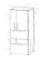
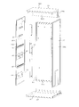
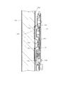
- the perspective view which shows the external appearance which looked at the heat insulation cabinet from upper direction The perspective view which shows the external appearance which looked at the heat insulation cabinet from the lower part
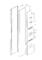
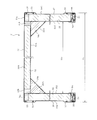
- disassembles and shows the heat insulation panel for left side walls Transverse plan view of insulated cabinet Longitudinal front view of the corners of the left side wall insulation panel and ceiling wall insulation panel
- FIG. 10 is a cross-sectional plan view of the front portion of the left-side wall heat insulation panel at a portion different from Fig. 10.
- Front view of hinge part Transverse plan view taken along section line X13-X13 in FIG.
- Cross-sectional plan view along section line X14-X14 in FIG. Longitudinal side view taken along section line X15-X15 in FIG.
- the refrigerator 1 is mainly composed of a heat insulating cabinet 2.
- the heat insulating cabinet 2 includes a refrigerated room 3, a vegetable room 4, an ice making room 5, a small freezer room 6, and a main freezer room 7.
- the refrigerator compartment 3 is provided in the uppermost part of the heat insulation cabinet 2.
- the vegetable compartment 4 is provided below the refrigerator compartment 3.
- the ice making room 5 and the small freezer room 6 are provided side by side on the lower side of the vegetable room 4.
- the main freezer compartment 7 is provided below the ice making compartment 5 and the small freezer compartment 6, that is, at the lowermost part of the heat insulation cabinet 2.
- Refrigerated room 3, vegetable room 4, ice making room 5, small freezer room 6, and main freezer room 7 each form a storage room.
- the refrigerator compartment 3 and the vegetable compartment 4 are storage compartments in a refrigerator temperature zone, and the internal temperature is controlled to 0 ° C. to 10 ° C., for example.
- the refrigerator compartment 3 and the vegetable compartment 4 should just be able to ensure a certain amount of heat insulation, for example, it is partitioned off by the synthetic resin refrigerator compartment bottom board 8 which is a board member.
- the ice making room 5, the small freezer room 6, and the main freezer room 7 are storage rooms in a freezing temperature zone, and the internal temperature is controlled to be, for example, ⁇ 18 ° C. or lower, which is a freezing temperature zone.
- the vegetable compartment 4 in the refrigerated temperature zone and the ice making chamber 5 and the small freezer compartment 6 in the freezing temperature zone are partitioned vertically by a heat insulating partition wall 9 having heat insulating properties.
- the heat insulating partition wall 9 reduces heat leakage between the refrigerated temperature zone vegetable room 4 and the freezing temperature zone ice making room 5 and small freezer room 6.
- the refrigerator compartment bottom plate 8 constitutes the bottom plate of the refrigerator compartment 3, and stored items are placed thereon.
- front partition members 10, 11, 12, and 13 are provided at the front portion of the heat insulation cabinet 2.
- the front partition member 10 is positioned in front of the refrigerator compartment bottom plate 8 and extends in the left-right lateral direction.
- the front partition member 11 is positioned in front of the heat insulating partition wall 9 and extends in the left-right lateral direction.
- the front partition member 12 is positioned between the ice making chamber 5 and the small freezer compartment 6 and extends in the vertical direction.
- the front partition member 13 is located between the ice making chamber 5 and the small freezer compartment 6 and the main freezer compartment 7 and extends in the horizontal direction.
- the refrigerator compartment 3 includes two left and right rotating doors 15 and 16.
- the rotary doors 15 and 16 open and close the front surface of the refrigerator 3.
- the heat insulating cabinet 2 has hinge members 17 a, 17 b, 18 a, and 18 b provided at the upper and middle portions of the left and right ends.
- the revolving doors 15 and 16 are double doors that are rotated in the front-rear direction around the hinge members 17a, 17b, 18a, and 18b.
- the left rotating door 15 is rotatably supported by a pair of upper and lower hinge members 17a and 17b.
- one hinge member 17 b is provided at the front edge of the left-side wall heat insulation panel 26 that constitutes the heat insulation cabinet 2 and is provided at a substantially middle portion in the vertical direction.
- the other hinge member 17 a is provided on the left side of the front edge of the ceiling wall heat insulating panel 28, which is a ceiling wall constituting the heat insulating cabinet 2.
- the hinge member 17a has a hinge shaft 17aj protruding downward.
- the hinge member 17b has a hinge shaft 17bj protruding upward.
- the left-side rotary door 15 is rotatably supported by the hinge shaft portions 17aj and 17bj.
- the right rotating door 16 is rotatably supported by a pair of upper and lower hinge members 18a and 18b.
- one hinge member 18 b is provided at the front edge of the right-side wall heat insulation panel 27 that constitutes the heat insulation cabinet 2 and is provided at a substantially middle portion in the vertical direction.
- the other hinge member 18a is provided on the left part of the front edge of the ceiling wall heat insulation panel 28.
- the hinge member 18a has a hinge shaft 18aj protruding downward.
- the hinge member 18b has a hinge shaft 18bj protruding upward.
- the right side rotary door 16 is rotatably supported by the hinge shafts 18aj and 18bj.
- the front of the vegetable compartment 4 is opened and closed by a pull-out door 19.
- a vegetable storage container (not shown) is provided on the back side of the door 19.
- the front surface of the ice making chamber 5 is opened and closed by a drawer-type door 20.
- the ice making chamber 5 is provided with an ice making device (not shown).
- An ice storage container (not shown) is provided on the back side of the door 20.
- the front surface of the small freezer compartment 6 is opened and closed by a drawer-type door 21.
- a storage container (not shown) is provided on the back side of the door 21.
- the front surface of the main freezer compartment 7 is also opened and closed by a drawer type door 22.
- a storage container (not shown) is provided on the back side of the door 22.
- the vegetable compartment 4, the ice making compartment 5, the small freezer compartment 6, and the main freezer compartment 7, which are storage compartments opened and closed by the drawer type doors 19, 20, 21, and 22, are the capacities of the respective compartments 4, 5, 6, and 7. But they are different. In this case, the capacity of each storage room 4, 5, 6, 7 is larger in the order of the main freezer room 7, the vegetable room 4, the small freezer room 6, and the ice making room 5. Of these storage chambers 4, 5, 6, and 7, the main freezing chamber 7 having a large volume is provided below the other storage chambers, in this case the vegetable chamber 4, the ice making chamber 5, and the small freezing chamber 6.
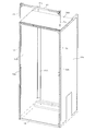
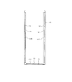
- the heat insulation cabinet 2 as a heat insulation box includes a plurality of heat insulation walls, in this case, a rear wall heat insulation panel 25, a left wall heat insulation panel 26, a right wall heat insulation panel 27, and a ceiling.
- the heat insulation panel 28 for walls and the heat insulation panel 29 for bottom walls it is comprised in the rectangular box shape long in the up-down direction which the front surface opened.
- the heat insulation panel 25 for the rear wall constitutes the rear wall of the heat insulation cabinet 2.
- the left side wall heat insulation panel 26 constitutes the left side wall of the heat insulation cabinet 2.
- the heat insulation panel 27 for the right side wall forms the right side wall of the heat insulation cabinet 2.
- the heat insulating panel 28 for the ceiling wall forms the ceiling wall of the heat insulating cabinet 2.
- the heat insulating panel 29 for the bottom wall constitutes the bottom wall of the heat insulating cabinet 2.
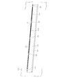
- the left-side wall heat insulation panel 26 includes an outer plate 30 ⁇ / b> B, an inner plate 31 ⁇ / b> B, and a vacuum heat insulation panel 32.
- the vacuum heat insulation panel 32 is configured in a plate shape and is provided between the outer plate 30B and the inner plate 31B and functions as a heat insulating material.
- the left-side wall heat insulating panel 26 has a configuration in which the vacuum heat insulating panel 32 is interposed between the outer plate 30B and the inner plate 31B.
- the outer plate 30 ⁇ / b> B is a metal plate and constitutes an outer box of the heat insulating cabinet 2.
- the inner plate 31B is a sheet-like member made of synthetic resin, for example, and constitutes an inner box of the heat insulating cabinet 2.
- the inner plate 31B when referring to the surface, it refers to the surface inside the refrigerator, and when referring to the back surface, it refers to the surface opposite to the interior of the refrigerator, that is, the surface on the vacuum heat insulation panel 32 side.
- the inner plate 31 ⁇ / b> B of the left side wall heat insulating panel 26 includes a shelf receiving member 40, a refrigerator compartment bottom plate mounting member 41, a first rail mounting member 42, a partition wall mounting member 43, a second A rail attachment member 44 and a support 65 are attached.
- the inner plate 31B integrally includes the shelf receiving member 40, the refrigerator compartment bottom plate mounting member 41, the first rail mounting member 42, the partition wall mounting member 43, the second rail mounting member 44, and the support 65. In the state, it is bonded to the vacuum heat insulation panel 32.
- one surface of the vacuum heat insulation panel 32 is bonded to the back surface of the inner plate 31B with an adhesive (not shown). Moreover, the vacuum heat insulation panel 32 has the other surface opposite to the one surface bonded to the inner surface of the outer plate 30B with an adhesive (not shown). Thereby, the vacuum heat insulation panel 32 is being fixed in the state pinched
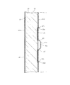
- the vacuum heat insulation panel 32 is comprised from the core material 35, such as glass wool, and the packaging material 38 which has gas barrier property, as shown in FIG. 16, FIG.
- the vacuum heat insulating panel 32 is configured in a panel shape, that is, a plate shape by housing the core material 35 in the packaging material 38 and evacuating the packaging material 38 in this state.
- the inner plate 31C of the right side wall heat insulation panel 27 facing the inner plate 31B of the left side wall heat insulation panel 26 is also provided with a shelf receiving member 40, a cold room bottom plate attachment member 41, and a first rail use.
- An attachment member 42, a partition wall attachment member 43, a second rail attachment member 44, and a support 65 are provided.
- the shelf receiving member 40 of the right-side wall heat insulating panel 27 faces the shelf receiving member 40 of the left-side wall heat insulating panel 26.
- the refrigerating chamber bottom plate mounting member 41 of the right side wall heat insulating panel 27 faces the refrigerating chamber bottom plate mounting member 41 of the left side wall heat insulating panel 26.
- the first rail mounting member 42 of the right-side wall heat insulation panel 27 faces the first rail mounting member 42 of the left-side wall heat insulation panel 26.
- the partition wall mounting member 43 of the right side heat insulating panel 27 faces the partition wall mounting member 43 of the left side wall heat insulating panel 26.
- the second rail mounting member 44 of the right side wall heat insulation panel 27 faces the second rail mounting member 44 of the left side wall heat insulation panel 26.
- the support member 65 of the right side wall heat insulation panel 27 faces the support member 65 of the left side wall heat insulation panel 26.
- the rear wall heat insulation panel 25 is also configured with a vacuum heat insulation panel 32 between the outer plate 30 ⁇ / b> A and the inner plate 31 ⁇ / b> A, similarly to the left wall heat insulation panel 26.
- the heat insulating panel 28 for the ceiling wall includes an outer plate 30 ⁇ / b> D, an inner plate 31 ⁇ / b> D, a vacuum heat insulating panel 32, and a urethane foam 33 that is a heat insulating material.
- the outer plate D is composed of a metal plate.
- the inner plate 31D is formed of an integrally molded product of synthetic resin.
- the vacuum heat insulation panel 32 of the heat insulation panel 28 for ceiling walls is fixed to the back surface of the inner plate 31D by adhesion or the like. Between the vacuum heat insulation panel 32 and the outer plate 30D, foamed urethane 33 is filled.
- the vacuum heat insulation panel 32 has a lower thermal conductivity and higher heat insulation performance than the urethane foam 33.
- the heat insulating panel 28 for the ceiling wall has a machine room 28 k that is in the upper rear part and is recessed in an L shape. A compressor 36 of the refrigeration cycle is accommodated in the machine room 28k.
- the bottom wall heat insulation panel 29 has a vacuum heat insulation panel and urethane foam between the outer plate 30E and the inner plate 31E, similarly to the heat insulation panel 28 for the ceiling wall.
- the outer plates 30A to 30E constitute the outer surface of the heat insulating cabinet 2, that is, the cabinet outer surface.
- the inner plates 31A to 31B constitute the inner surface of the heat insulating cabinet 2.
- the rear wall heat insulation panel 25 and the left wall heat insulation panel 26 are connected to each other by a fixture 23 ⁇ / b> A, a screw (not shown), or the like at the left rear corner.
- the rear wall heat insulation panel 25 and the right wall heat insulation panel 27 are connected to each other at the corner portion of the right rear portion by a fixture 23B similar to the fixture 23A, screws, or the like.
- heat insulating materials 34a to 34c such as foamed polystyrene, soft tape, and sponge tape are appropriately provided.
- the heat insulating panel 28 for the ceiling wall and the heat insulating panel 29 for the bottom wall are connected to the heat insulating panels 25 to 27 as appropriate.
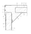
- the front part of the left-side wall heat insulation panel 26 and the front part of the right-side wall heat insulation panel 27 are connected by front partition members 10, 11, 12, and 13.
- the left and right front edges that is, the front edge of the left wall heat insulation panel 26 and the front edge of the right wall heat insulation panel 27 are These are reinforced by the longitudinal reinforcing members 51, 51. Further, the upper reinforcing member 52 reinforces the upper front edge and the left and right front edges.
- the members 40 to 44 and 65 are not shown in order to avoid complexity of the drawings.
- the vertical dimension of the vertical reinforcing member 51 is set to be approximately the same as the vertical dimension of the left side wall heat insulation panel 26.
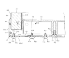
- the cross-sectional shape of the vertical reinforcing member 51 is configured as a groove having an outer plate portion 51a, an intermediate plate portion 51b, and an inner plate portion 51c, with the rear side being opened.
- a part of the vertical reinforcing member 51 that is, a connecting portion with the front partition members 10, 11, 13 is formed in an L shape with the inner plate portion 51c cut away as shown in FIGS. Yes.
- the vertical reinforcing member 51 is inserted into the front edge portion of the left-side wall heat insulation panel 26 from above or from below.
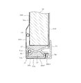
- the bent portion 30 b of the outer plate 30 ⁇ / b> B moves away from the front end portion of the vacuum heat insulation panel 32 to the front side. That is, the bent portion 30b of the outer plate 30B is located in front of the vacuum heat insulation panel 32 and is separated from the vacuum heat insulation panel 32, and the end on the opening side of the heat insulation cabinet 2, that is, the front end is bent to the inside of the cabinet.
- the bent portion 30b has an outer bulging portion 30b1, an intermediate portion 30b2, and an inner extending portion 30b3.
- the outer bulging portion 30b1 bulges slightly outside the front portion 30a of the outer plate 30B and is separated from the vacuum heat insulating panel 32.
- the intermediate portion 30b2 is bent inward at the front end of the outer bulging portion 30b1.
- the inner extending portion 30b3 is formed in an L shape that is bent backward from the inner end of the intermediate portion 30b2.
- the bent portion 30b of the outer plate 30B is configured in a groove shape with the rear side opened.
- the vertical reinforcing member 51 is inserted in a form that fits inside the groove shape of the bent portion 30b, and is connected to the outer plate 30B by bonding or screwing. Further, the vertical reinforcing member 51 is separated from the inner plate 31B. That is, the vertical reinforcing member 51 is not connected to the inner plate 51B. In other words, the vertical reinforcing member 51 and the inner plate 51B are not connected.
- a heat radiating pipe 53 for the refrigeration cycle is disposed between the vacuum heat insulation panel 32 and the outer bulging portion 30b1.
- a synthetic resin seal member 54 is provided between the inner plate 31B and the bent portion 30b of the outer plate 30B to seal the space therebetween.
- the seal member 54 has a pipe holder portion 54 a that fixes a dew-proof pipe 55 that prevents condensation on the front surface of the heat-insulating cabinet 2.
- the dewproof pipe 55 is constituted by a part of the heat radiating pipe of the refrigeration cycle.
- the heat radiating pipe 53 is also provided in the rear part of the heat insulation panel 26 for left side walls, and the heat insulation panel 27 for right side walls, as shown in FIG.
- heat insulating materials 37 and 37 made of, for example, soft tape are provided in the front portion 30a of the outer plate 30B.
- the upper reinforcing member 52 includes an intermediate plate portion 52a, a left plate portion 52b, and a right plate portion 52c.
- the left plate portion 52b and the right plate portion 52c are configured to hang at right angles from both end portions of the intermediate plate portion 52a.
- the left and right plate portions 52b and 52c are inserted into the front portions of the left-side wall heat insulation panel 26 and the right-side wall heat insulation panel 27 from above.
- the left and right plate portions 52b and 52c are fixed in contact with the inner surface of the vertical reinforcing member 51, as shown in FIG. In this way, the intermediate plate portion 52a is fixed to the front edge portion of the ceiling wall heat insulating panel 28.
- the relatively heavy compressor 36 is provided at the rear of the heat insulating cabinet 2.
- the vertical reinforcing member 51 and the upper reinforcing member 52 are provided in front of the heat-insulating cabinet 2, that is, in front of the compressor 36. For this reason, the vertical reinforcing member 51 and the upper reinforcing member 52 contribute to the equalization of the front and rear weights in the heat insulating cabinet 2.
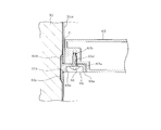
- the hinge member 17 b is provided at a connection portion between the left side wall heat insulation panel 26 of the heat insulation cabinet 2 and the front partition member 10. Further, as shown in FIG. 2, the hinge member 18 b is provided at a connecting portion between the right-side heat insulating panel 27 and the front partition member 10. Since the attachment structure of each hinge member 17b, 18b is bilaterally symmetrical, the hinge member 17b part is demonstrated.
- the vertical reinforcing member 51 is formed in an L shape by cutting off a part of the inner plate portion 51c shown in FIG. Similarly, the inner extension 30b3 of the outer plate 30B shown in FIG. 10 is also cut away.
- a reinforcing contact member 56 is provided across the back surface of the left vertical reinforcing member 51 and the back surface of the front partition member 10.
- the hinge member 17 b is provided across the front surface of the left-side wall heat insulation panel 26 and the front surface of the front partition member 10. That is, for example, three screw insertion holes 17b1, 17b2, and 17b3 are formed in the hinge member 17b.
- a screw insertion hole 30m is formed in the intermediate portion 30b2 of the outer plate 30B.
- a screw insertion hole 51b1 is formed in the intermediate plate portion 51b of the vertical reinforcing member 51.
- the screw screw holes 56a, 56b, and 56c are formed in the reinforcing contact member 56.
- the screw screw holes 56a, 56b and 56c include a female screw part and a tapping hole part.
- the reinforcing contact member 56 is formed with a recessed portion 56d that is recessed in a dish shape.
- a screw insertion hole 56e is formed at the bottom of the recess 56d.
- the front partition member 10 is formed with screw insertion holes 10a and 10b.
- the reinforcing contact member 56 is disposed on the back side of the vertical reinforcing member 51 and the front partition member 10.
- the hinge member 17b is disposed on the front surface of the intermediate portion 30b2 of the outer plate 30B and the front surface of the front partition member 10.
- the screw 57a is passed through the screw insertion hole 17b1 of the hinge member 17b, the screw insertion hole 30m of the outer plate 30B, and the screw insertion hole 51b1 of the vertical reinforcing member 51.
- the screw 57 a is screwed into the screw screw hole 56 a of the reinforcing member 56.
- the screw 57 b is passed through the screw insertion hole 17 b 2 of the hinge member 17 b and the screw insertion hole 10 a of the front partition member 10. Then, the screw 57 b is screwed into the screw screw hole 56 b of the reinforcing contact member 56.
- the screw 57c is passed through the screw insertion hole 17b3 of the hinge member 17b and the screw insertion hole 10b of the front partition member 10. Then, the screw 57 c is screwed into the screw screw hole 56 c of the reinforcing contact member 56.
- the hinge member 17b is fixed to a connecting portion between the front partition member 10 and the left-side wall heat insulating panel 26.
- a part of the hinge member 17 b is fixed to the vertical reinforcing member 51. That is, a part of the hinge member 17 b is connected to the vertical reinforcing member 51 via the reinforcing contact member 56.
- the upper hinge members 17a and 18a are provided on the upper surface side of the ceiling wall heat insulating panel 28 at the left and right corner portions of the upper reinforcing member 52, that is, the connection portions between the intermediate plate portion 52a and the left and right plate portions 52b and 52c. It is fixed in the vicinity by screws.
- a partition back cover 58 made of synthetic resin is provided on the back side of the front partition member 10.
- the partition back cover 58 is provided in advance on the reinforcing pad member 56 before the front partition member 10 is attached to the reinforcing pad member 56.
- the reinforcing contact member 56 is formed with a screw insertion hole 56e.
- a countersunk screw 59 is passed through the screw insertion hole 56e.
- the countersunk screws 59 passed through the screw insertion holes 56 e are screwed into the partition back cover 58 disposed on the back side of the reinforcing pad member 56.
- the front partition member 10 is attached to the reinforcing member 56.
- the partition back cover 58 is fixed to the front partition member 10 via the reinforcing contact member 56.
- the connection portion will be described as a representative with reference to FIGS.
- connection part of the front partition member 11 and the heat insulation panel 27 for right side walls is comprised symmetrically with the connection part of the front partition member 11 and the heat insulation panel 26 for left side walls.
- the vertical reinforcing member 51 is formed in an L shape in which a part of the inner plate portion 51c shown in FIG. Further, the outer plate 30B is also cut away from the inner extending portion 30b3 shown in FIG. A reinforcing contact member 61 is provided across the back surface of the vertical reinforcing member 51 and the back surface of the front partition member 11. The front partition member 11 is connected to the vertical reinforcing member 51 via the reinforcing contact member 61.
- a screw insertion hole 30n is formed in the intermediate portion 30b2 of the outer plate 30B.
- a screw insertion hole 51b2 is formed in the intermediate plate portion 51b of the vertical reinforcing member 51.
- the reinforcing abutting member 61 is formed with three screw threaded hole portions 61a, 61b, 61c and a recessed portion 61d that is recessed in a dish shape.
- a screw insertion hole 61e is formed at the bottom of the recess 61d.
- the front partition member 11 is formed with screw insertion holes 11a and 11b.
- the reinforcing contact member 61 is disposed behind the longitudinal reinforcing member 51 and the front partition member 11. Then, the screw 62a is passed through the screw insertion hole 30n of the outer plate 30B and the screw insertion hole 51b2 of the vertical reinforcing member 51. Then, the screw 62 a is screwed into the screw screw hole 61 a of the reinforcing member 61. Similarly, the screw 62 b is passed through the screw insertion hole 11 a of the front partition member 11, and the screw 62 c is passed through the screw insertion hole 11 b of the front partition member 11.
- the screw 62 b is screwed into the screw screw hole 61 b of the reinforcing pad 61 and the screw 62 c is screwed into the screw screw hole 61 c of the reinforcing pad 61.
- the front partition member 11 and the vertical reinforcing member 51 are fixed to each other by the reinforcing contact member 61.
- a partition back cover 63 made of synthetic resin is provided on the back side of the front partition member 11.
- the partition back cover 63 is provided in the reinforcing contact member 61 in advance when the front partition member 11 is attached to the left-side wall heat insulation panel 26.
- the reinforcing abutting member 61 is formed with a screw insertion hole 61e.
- a countersunk screw 64 is passed through the screw insertion hole 61e.
- the countersunk screw 64 passed through the screw insertion hole 61 e is screwed into the partition back cover 63 disposed on the back side of the reinforcing pad member 61.
- the front partition member 11 is attached to the reinforcing member 61.
- the partition back cover 63 is fixed to the front partition member 11 via the reinforcing contact member 61.
- the partition back cover 63 is supported by a support 65 provided on the left-side wall heat insulation panel 26.
- the support tool 65 is made of, for example, a synthetic resin, and integrally includes a protruding portion 65a and extending portions 65b and 65c.
- the protrusion 65a is configured in a rectangular block shape.
- the protrusion 65a has a screw insertion hole 65d and a counterbore 65e.
- the screw insertion hole 65d is formed by penetrating the protrusion 65a in a vertical direction in a circular shape.
- the screw insertion hole 65d is formed in a long hole shape that is slightly longer in the left-right direction.
- the counterbore part 65e has an inner diameter larger than the inner diameter of the screw insertion hole part 65d, and is formed so as to be recessed from the lower surface of the protrusion part 65a upward to the middle part of the thickness of the protrusion part 65a.
- the extending portions 65b and 65c are formed in a rectangular plate shape extending in the vertical direction from the horizontal end portion of the protruding portion 65a, in this case, the end portion on the inner plate 31B side.
- the thickness dimension of the extending parts 65b and 65c in the horizontal direction is smaller than the thickness dimension of the protruding part 65a in the vertical direction.
- a hole 31k is formed in the inner plate 31B.
- the hole 31k is formed through the inner plate 31B in a rectangular shape that is slightly larger than the protruding portion 65a and smaller than the outer shape of the extending portions 65b and 65c.
- the support 65 is provided on the inner plate 31B when the left-side wall heat insulation panel 26 is assembled.
- the protrusion 65a of the support tool 65 is passed through the hole 31k of the inner plate 31B from the inner side to the outer side of the left side wall heat insulating panel 26, that is, from the vacuum heat insulating panel 32 side toward the inner side.
- An adhesive or the like is provided between the extending portions 65b and 65c and the inner plate 31B and between the extending portions 65b and 65c and the vacuum heat insulating panel 32.
- the support tool 65 is bonded and fixed to the inner plate 31B and the vacuum heat insulation panel 32 in a state where the extension portions 65b and 65c are sandwiched between the inner plate 31B and the vacuum heat insulation panel 32.
- the partition back cover 63 has a supported portion 63a.
- the supported portion 63a is formed in the lower part of the partition back cover 63, and a portion corresponding to the support 65 is recessed from below to above.
- the supported portion 63a has a screw screw hole portion 63b formed from the lower side toward the upper side.
- the protruding portion 65a of the support tool 65 enters the supported portion 63a.
- a screw 66 passed through the screw insertion hole portion 65d is screwed into the screw screw hole portion 63b of the supported portion 63a. Accordingly, the supported portion 63 a provided at the lower portion of the partition back cover 63 is supported by the support tool 65, and is fixed to the support tool 65 by the screw 66.
- the left and right length dimensions of the partition back cover 63 are set so that a gap G is generated in advance between the left side wall heat insulation panel 26 and the right side wall heat insulation panel 27. That is, the left side wall heat insulation panel 26 and the right side wall heat insulation panel 27 are assembled on the basis of the width dimension Hs outside the heat insulation cabinet 2 shown in FIG. In this case, the variation in the thickness dimension generated in the left-side wall heat insulation panel 26 and the right-side wall heat insulation panel 27 is absorbed by changing the width dimension Hu inside the heat insulation cabinet 2. Thereby, the variation in the thickness dimension of the right and left side heat insulating panels 26 and 27 that occurs in the manufacturing process of the left and right side heat insulating panels 26 and 27 is allowed to some extent.
- the width dimension Hu inside the heat insulation cabinet 2 becomes the minimum value.
- the left and right length dimensions of the partition back cover 63 are set so that the gap G is generated even when the inner width dimension Hu of the heat insulating cabinet 2 is the minimum value.
- this gap G is slight.
- the gap G may be filled with a heat insulating material such as soft tape.
- a shelf receiving member 40 a refrigerator compartment bottom plate mounting member 41, a first rail mounting member 42, a partition wall mounting member 43, and a second rail mounting provided on the left side wall heat insulation panel 26
- the member 44 will be described.
- the shelf receiving member 40 has a plurality of projecting portions 40 a and 40 b and an extending portion 40 c.
- the extending part 40c is configured in a rectangular plate shape that is long in the vertical direction.
- the protruding portions 40a and 40b are formed in a bowl shape facing upward, and protrude from the left and right ends of the extending portion 40c to the inside of the warehouse.
- the protrusions 40a are paired with two left and right protrusions 40a.
- the protrusions 40b are paired with two left and right protrusions 40b.
- the protrusion 40b is provided below the protrusion 40a.
- the shelf receiving member 40 is configured, for example, by punching the protruding portions 40a and 40b and the extending portion 40c from a metal plate, and then bending the protruding portions 40a and 40b.
- a shelf (not shown) is placed on the bowl-shaped protrusions 40 a and 40 b of the shelf receiving member 40.
- the inner plate 31B is formed with holes 31a and 31b that are separated from each other in the vertical direction.
- the holes 31a and 31b are formed by penetrating the inner plate 31B into a rectangular shape into which the pair of protrusions 40a and 40b can be inserted.
- the protruding portions 40a and 40b of the shelf receiving member 40 are inserted into the holes 31a and 31b from the back surface side of the inner plate 31B and protrude to the front surface side of the inner plate 31B.
- the extending part 40c is bonded to the rear surface of the inner plate 31B and the peripheral parts of the hole parts 31a and 31b. As shown in FIG.
- the shelf receiving member 40 is fixed in a state where the extending portion 40 c is sandwiched between the inner plate 31 ⁇ / b> B and the vacuum heat insulating panel 32.
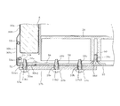
- the refrigerating room bottom plate mounting member 41 also serves as a reinforcing member mounting portion, and is provided on the lower side of the refrigerating room bottom plate 8 as shown in FIG. As shown in FIGS. 18 and 19, the refrigerator compartment bottom plate mounting member 41 is formed in a long shape extending in the front-rear direction as a whole.
- the refrigerator compartment bottom plate mounting member 41 integrally includes a projecting portion 41a, an extending portion 41b, and an engaging portion 41c.
- the protruding portion 41a, the extending portion 41b, and the engaging portion 41c are integrally formed, for example, by bending a metal plate.
- the extending portion 41b is formed in a rectangular plate shape that is parallel to the inner plate 31B, that is, substantially perpendicular and long in the front-rear direction.
- the protruding portion 41a is formed by being bent substantially horizontally from the upper edge portion of the extending portion 41b to the inside of the warehouse.
- the engaging portion 41c is formed by being bent substantially horizontally from the lower edge portion of the extending portion 41b toward the inside of the cabinet, and further, the end portion inside the warehouse is bent substantially vertically downward.
- the longitudinal section from the projecting portion 41a to the extending portion 41b is formed in an L shape.
- the protruding portion 41a and the extending portion 41b are continuous so that the longitudinal section thereof is L-shaped.
- the vertical cross-section of the refrigerator compartment bottom plate mounting member 41 has a groove shape in which the inside of the refrigerator is opened as a whole.
- the arrangement hole 41d is a slit-shaped connecting hole extending in the longitudinal direction of the protrusion 41a, that is, extending in the front-rear direction.
- the screw insertion hole 41e is a connecting hole made of a long hole that is long in the left-right direction.
- holes 31d and 31e are formed in the inner plate 31B.
- the holes 31d and 31e are formed in a slit shape. A protrusion 41a is inserted into the hole 31d from the back side of the inner plate 31B.
- the engaging portion 41c is inserted into the hole portion 31e from the back side of the inner plate 31B. And the extension part 41b of the attachment member 41 for cold room bottom plates is adhere
- the attachment member 41 for the refrigerator compartment bottom plate is improved in attachment strength to the left-side wall heat insulation panel 26 by engaging the engaging portion 41c and the hole portion 31e.
- the refrigerator compartment bottom plate mounting member 41 is provided to be paired with the left and right inner plates 31B and 31C.
- One end and the other end of a bridge-shaped reinforcing member 71 are connected to the left and right refrigerator compartment bottom plate mounting members 41, 41.
- the bridge-shaped reinforcing member 71 is configured, for example, by bending upward both ends of a rectangular metal plate that is long in the left-right direction.
- One end portion and the other end portion of the bridge-shaped reinforcing member 71 are provided in the central portion in the front-rear direction of the refrigerator compartment bottom plate mounting members 41, 41.
- a screw 72 is passed from below through the screw insertion hole 41e at the center in the front-rear direction of the mounting members 41, 41 for the refrigerator compartment bottom plate.
- the screw 72 is screwed into the bridge-shaped reinforcing member 71.
- the both ends of the bridge-like reinforcing member 71 are fixed to the left and right refrigerator compartment bottom plate mounting members 41, 41.
- the left and right refrigerator compartment bottom plate attachment members 41, 41 are connected to each other by the bridge-like reinforcing member 71.
- the screw insertion hole 41e is formed of a long hole that is long in the left-right direction. Therefore, the connecting position of the bridge-shaped reinforcing member 71 can be adjusted with respect to the left and right refrigerator compartment bottom plate attachment members 41. Therefore, the bridge-shaped reinforcing member 71 can be satisfactorily attached to the left and right refrigerator compartment bottom plate attachment members 41 even if the thickness dimensions of the left and right side heat insulating panels 26 and 27 vary.
- the heat insulation panels 26 and 27 for the left and right side walls are assembled on the basis of the width dimension Hs outside the heat insulation cabinet 2 shown in FIG.
- the variation in the thickness dimension of the left and right side heat insulating panels 26 and 27 is absorbed by changing the inner width dimension Hu of the heat insulating cabinet 2.
- the screw insertion hole 41e is formed as a long hole that is larger than the diameter of the screw 72 and long in the left-right direction in order to cope with a change in the width dimension Hu inside the heat insulating cabinet 2.
- the attachment position of the bridge-shaped reinforcement member 71 with respect to the attachment member 41 for refrigerator compartment bottom plates can be adjusted according to the change of the width dimension Hu inside the heat insulation cabinet 2.
- the bridge-shaped reinforcing member 71 is firmly connected to the refrigerator compartment bottom plate attachment member 41 by screws 72 after the attachment positions of the left and right refrigerator compartment bottom plate attachment members 41 and 41 are adjusted. For this reason, it can suppress effectively that the heat insulation panels 26 and 27 for right and left side walls deform
- the refrigerator compartment bottom plate 8 has an engaging projection (not shown) protruding downward from the lower surface side.
- the refrigerator compartment bottom plate 8 is arranged by fitting the engaging protrusions into the arrangement hole 41 d from above the refrigerator compartment bottom plate attachment member 41.
- the relatively heavy compressor 36 is provided near the rear part of the heat insulating cabinet 2.
- the bridge-shaped reinforcing member 71 is provided near the front portion of the heat-insulating cabinet 2. Therefore, the bridge-like reinforcing member 71 contributes to the equalization of the front and rear weights in the heat insulating cabinet 2.
- the first rail mounting member 42 is configured by integrally including a protruding portion 42a, an extending portion 42b, an upper engaging portion 42c, and a lower engaging portion 42d, for example, using a metal plate. ing.
- the protruding part 42a protrudes inward from the inner plate 31B and is formed in a substantially cylindrical shape with the bottom on the inner side closed. In this case, the protrusion 42a is formed in a cylindrical shape close to a bowl shape.
- the extending part 42b is formed in a plate shape extending in the vertical direction around the skirt of the protruding part 42a.
- One upper engaging portion 42c is provided at the center of the extending portion 42b in the front-rear direction at the upper portion of the extending portion 42b.
- the upper engaging portion 42c protrudes upward in an L shape. That is, the upper engaging portion 42c is bent so as to protrude from the upper end portion of the extending portion 42b to the inside of the warehouse, and the protruding tip portion is bent upward.
- Two lower engaging portions 42d are provided in the lower part of the extending portion 42b and in the front-rear direction of the extending portion 42b. The lower engaging portion 42d is bent so as to protrude from the lower end portion of the extending portion 42b to the inside of the warehouse.
- a screw screw hole 42e is formed in the protruding portion 42a.
- the inner plate 31B has a hole 31f formed through the inner plate 31B in a circular shape.
- the protrusion 42a of the first rail mounting member 42 is inserted into the hole 31f from the back side of the inner plate 31B and protrudes from the hole 31f to the inside of the warehouse.
- the inner plate 31B is formed with an upper engagement hole 31g and a lower engagement hole 31h.
- the upper engagement hole 31g and the lower engagement hole 31h are formed through the inner plate 31B in a slit shape that is long in the front-rear direction.
- the upper engagement hole 31g is formed at one place above the hole 31f.
- the lower engagement hole 31h is formed below the hole 31f and at two locations in the front-rear direction.
- the attachment of the first rail attachment member 42 to the inner plate 31B is performed as follows. First, the upper engaging portion 42c of the first rail mounting member 42 is inserted into the upper engaging hole portion 31g from the back surface side of the inner plate 31B. And while rotating the 1st rail attachment member 42 to the inner-plate 31B side centering
- the extending part 42b is also bonded to the vacuum heat insulating panel 32 with an adhesive or the like.
- the extending part 42b is fixed to the inner plate 31B and the vacuum heat insulation panel 32 by adhesion in a state sandwiched between the inner plate 31B and the vacuum heat insulation panel 32.
- a rail 45 is attached to the first rail attachment member 42 as shown in FIG.
- the rail 45 extends in the front-rear direction, and guides the movement in the front-rear direction of a support frame (not shown) attached to the back side of the door 19 of the vegetable compartment 4.
- the rail 45 is fixed by screwing a screw into a screw screw hole 42e formed in the protrusion 42a of the first rail mounting member 42.
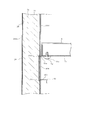
- the partition wall mounting member 43 also serves as a reinforcing member mounting portion, and as shown in FIG. 3, in the vicinity of the heat insulating partition wall 9, in this case, below the heat insulating partition wall 9 and extending in the front-rear direction. Is provided.
- the partition wall mounting member 43 will be described with reference to FIGS. 22 and 23.
- the partition wall mounting member 43 is configured similarly to the refrigerator compartment bottom plate mounting member 41. That is, the partition wall attachment member 43 is formed in a long shape extending in the front-rear direction as a whole from, for example, a metal plate.
- the partition wall mounting member 43 includes a protruding portion 43a, an extending portion 43b, and an engaging portion 43c.
- the projecting portion 43a, the extending portion 43b, and the engaging portion 43c are integrally formed, for example, by bending a metal plate.
- the extending portion 43b is formed in a rectangular plate shape that is parallel to the inner plate 31B, that is, substantially perpendicular and long in the front-rear direction.
- the protruding portion 43a is formed by being bent substantially horizontally from the upper edge portion of the extending portion 43b to the inside of the warehouse.
- the engaging portion 43c is formed by being bent substantially horizontally from the lower edge portion of the extending portion 43b toward the inside of the cabinet, and further, the end portion inside the cabinet is bent substantially vertically downward.
- the longitudinal section from the protruding portion 43a to the extending portion 43b is formed in an L shape. That is, the projecting portion 43a and the extending portion 43b are continuous so that the longitudinal section thereof is L-shaped.
- the vertical cross section of the partition wall mounting member 43 has a groove shape in which the inner side is opened as a whole.
- a plurality of arrangement holes 43d are formed in the protrusion 43a.
- the arrangement hole 43d is a slit-like connection hole extending in the longitudinal direction of the protrusion 43a, that is, extending in the front-rear direction.
- holes 31i and 31j are formed in the inner plate 31B.
- the holes 31i and 31j are formed in a slit shape.
- a protrusion 43a is inserted into the hole 31i from the back side of the inner plate 31B.
- the engaging portion 43c is inserted into the hole portion 31j from the back side of the inner plate 31B.
- the extending portion 43 b of the partition wall mounting member 43 is bonded to the back surface of the inner plate 31 ⁇ / b> B and the vacuum heat insulation panel 32 while being sandwiched between the back surface of the inner plate 31 ⁇ / b> B and the vacuum heat insulation panel 32.
- the engaging portion 43c and the hole portion 31j are engaged. Thereby, the attachment strength with respect to the heat insulation panel 26 for left side walls of the attachment member 43 for partition walls improves.
- the heat insulating partition wall 9 has a heat insulating material 9b such as urethane foam inside the outer casing portion 9a.
- a protruding portion 9c is formed integrally with the outer casing portion 9a.
- the protruding portion 9c is formed in a cylindrical shape that protrudes downward from the lower side surfaces of the left and right ends of the outer casing portion 9a. In FIG. 23, only the protrusion 9c at the left end is shown.
- the protrusion 9c is inserted into and engaged with the arrangement hole 43d of the partition wall attachment member 43 attached to the left and right side heat insulating panels 26 and 27.
- the heat insulation partition wall 9 is provided in the heat insulation cabinet 2 so that the inside of the heat insulation cabinet 2 may be divided up and down.
- the heat insulating partition wall 9 also serves as a bridge-shaped reinforcing member.
- the left and right lengths of the heat insulating partition wall 9 are set to lengths in which the gap G is generated in consideration of variations in the thickness dimensions of the left side wall heat insulating panel 26 and the right side wall heat insulating panel 27 in the same manner as the partition back cover 63. Has been.
- the inner diameter dimension in the left-right direction of the arrangement hole 43d is set to be slightly larger than the outer diameter dimension in the left-right direction of the protrusion 9c of the heat insulating partition wall 9. Thereby, the heat insulation partition wall 9 can adjust the connection position with respect to the partition wall attachment member 43.
- two second rail mounting members 44 are provided on the left and right sides of the main freezer compartment 7 in the front-rear direction.
- the second rail mounting member 44 has the same configuration as the first rail mounting member 42, and is similarly mounted on the inner plate 31B.
- the gap G may be appropriately filled with a heat insulating material such as soft tape.
- the heat insulating cabinet 2 has the vacuum heat insulating panel 32 as a heat insulating material between the outer plates 30A to 30E constituting the outer surface of the cabinet and the inner plates 31A to 31E constituting the inner surface. is doing.
- the vacuum heat insulation panel 32 has higher heat insulation performance than the urethane foam 33. Therefore, the heat insulation cabinet 2 can make the surrounding wall thin.
- the edges on the opening side of the left and right side walls tend to be weaker than other parts, and may be relatively easily deformed by the application of external force.
- the heat insulation cabinet 2 which aimed at thickness reduction of the surrounding wall using the vacuum heat insulation panel 32 like this embodiment, the influence of the external force added to the edge part by the side of the opening of the heat insulation panels 26 and 27 for right and left side walls is received. There is a risk that it will be larger. In this case, for example, if a load such as the rotary doors 15 and 16 is applied to the end of the front side of the heat insulating panels 26 and 27 for the left and right side walls, the right and left side heat insulating panels 26 and 27 may be deformed by the load. is there.
- the heat insulating cabinet 2 of the present embodiment has a vertical reinforcing member 51.
- the vertical reinforcing members 51 are provided at the front opening edge portions of the left side wall heat insulation panel 26 that is the left side wall and the right side wall heat insulation panel 27 that is the right side wall. According to this, the intensity
- the deformation of the left and right side wall heat insulation panels 26 and 27 in the bending direction by the cold room bottom plate mounting member 41 and the bridge-shaped reinforcing member 71 is suppressed when the thickness dimension of the left and right side wall heat insulation panels 26 and 27 is 35 mm or less. It is particularly effective.
- the vacuum heat insulation panel 32 has a thickness dimension of 20 mm, and the total thickness dimension of the outer plate 30B and the inner plate 31B is 1.5 mm. Therefore, the overall thickness dimension of the left and right side heat insulating panels 26 and 27 is 21.5 mm, which is an effective thickness dimension of 25 mm or less.
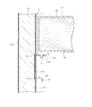
- the left-side wall heat insulation panel 26 has a bent portion 30b.
- the bent portion 30b is formed by bending an end portion on the opening side of the heat insulating cabinet 2 in the outer plate 30B, that is, a front end portion to the inside of the cabinet, and further bending the tip thereof to the rear side.
- the longitudinal reinforcing member 51 is provided along the inner surface of the bent portion 30b, that is, the surface on the vacuum heat insulating panel 32 side. According to this, in addition to the longitudinal reinforcing member 51, the bent portion 30b also contributes to the improvement of the strength of the front end portion of the left-side wall heat insulation panel 26. Therefore, the left-side wall heat insulation panel 26 is further strengthened, and thereby deformation due to external force is further suppressed.
- the heat insulation panel 27 for the right side wall is the same as the heat insulation panel 26 for the left side wall.
- the vertical reinforcing member 51 is not connected to the inner plate 31B. That is, the vertical reinforcing member 51 is not connected to the inner plate 31B.
- the longitudinal reinforcing member 51 is relatively strong against external force. Therefore, for example, when the outer plate 30B and the inner plate 31B are connected by the vertical reinforcing member 51, the outer plate 30B and the inner plate 31B are connected by the vertical reinforcing member 51 in the thickness direction of the vacuum heat insulating panel 32, that is, the outer plate 30B. Movement in the direction in which the plate 30B and the inner plate 31B are separated is restricted.
- the outer plate 30B and the inner plate 31B are joined to each other via the vacuum heat insulating panel 32, but are not joined to each other via the longitudinal reinforcing member 51. Accordingly, the outer plate 30B and the inner plate 31B are allowed to move relative to each other in the left-right direction, that is, in the thickness direction of the vacuum heat insulation panel 32 due to the change in the thickness dimension of the vacuum heat insulation panel 32. That is, when the thickness dimension of the vacuum heat insulation panel 32 varies, the outer plate 30 ⁇ / b> B and the inner plate 31 ⁇ / b> B can move relatively in the thickness direction of the vacuum heat insulation panel 32.
- the distance between the outer plate 30B and the inner plate 31B can follow the variation in the thickness dimension of the vacuum heat insulating panel 32. Therefore, even when the thickness dimension of the vacuum heat insulation panel 32 varies, it is possible to suppress an excessive force from acting on the outer plate 30B and the inner plate 31B. As a result, it is possible to prevent the outer plate 30B and the inner plate 31B from being deformed and an error from occurring in the outer width dimension Hs of the heat insulating cabinet 2 shown in FIG.
- the heat insulation panel 27 for the right side wall is the same as the heat insulation panel 26 for the left side wall.
- one hinge member 17b is provided on the left-side wall heat insulation panel 26, and the other hinge member 17a is provided on the ceiling wall heat insulation panel 28. .
- a part of the one hinge member 17 b is fixed to the vertical reinforcing member 51.
- the load applied to the hinge member 17 due to the load due to the weight of the rotary door 15 and the operation during opening and closing is large.
- the hinge member 17b is supported by the longitudinal reinforcing member 51 having relatively high strength. Therefore, the hinge member 17b is restrained from moving the attachment position or tilting the hinge shaft 17bj due to the load. Therefore, the rotation of the rotary door 15 can be maintained in a good state.
- the tilt of the hinge shaft 17bj is suppressed, the tilt of the rotary door 15 is also suppressed. Accordingly, it is possible to prevent an excessive force from being applied to the front end portion of the left-side wall heat insulation panel 26 due to the tilt of the rotary door 15. Thereby, the deformation
- the other hinge members 17a and 18a are provided at the left and right corner portions of the ceiling wall heat insulation panel 28, so that they have a relatively strong structure against the load caused by the rotary doors 15 and 16.
- the other hinge members 17a and 18a may be provided on the heat insulation panel 29 for the bottom wall.
- the reinforcing contact member 56 is provided on the back side of the vertical reinforcing member 51. A part of the hinge member 17 b is fixed to the vertical reinforcing member 51 via the reinforcing contact member 56. That is, the hinge member 17 b is supported by the vertical reinforcing member 51 and the reinforcing contact member 56. Therefore, it can suppress more effectively that the attachment position of the hinge member 17b falls, or the hinge member 17b inclines below. The same applies to the hinge member 18b.
- the refrigerator 1 includes a vegetable room 4, an ice making room 5, a small freezer room 6, and a main freezer room 7 as a plurality of storage rooms opened and closed by drawer type doors 19, 20, 21, and 22.
- the main freezing chamber 7 having a large volume is provided below the other storage chambers, in this case, the vegetable chamber 4, the ice making chamber 5, and the small freezing chamber 6. . According to this, it can suppress that the heat insulation cabinet 2 deform
- the doors 19 and 22 are supported by a rail 45 so as to be able to be taken in and out as shown in FIG.
- the rails for the doors 20 and 21 are not shown.
- Rails 45 and rails (not shown) that support the doors 20 and 21 are provided on the heat insulating panels 26 and 27 for the left and right side walls.
- loads due to the weight of the doors 19, 20, 21, 22 including the storage containers are applied to the heat insulation panels 26, 27 for the left and right side walls of the heat insulation cabinet 2 through the rail 45 and the like.
- the load by the weight of the doors 19, 20, 21, and 22 including a storage container becomes large, so that the volume of a storage chamber is large.
- the main freezer compartment 7 having a large volume is provided below the other storage rooms, in this case, the vegetable compartment 4, the ice making room 5, and the small freezer compartment 6.
- the weight of the door 22 and the storage container provided in the main freezer compartment 7 can be received by the right and left side heat insulating panels 26 and 27 in the vicinity of the bottom wall heat insulating panel 29. That is, in the heat insulation panels 26 and 27 for the left and right side walls, the vicinity of the heat insulation panel 29 for the bottom wall is connected to the heat insulation panel 29 for the bottom wall. Relatively difficult to deform.
- the door 22 and the storage container are received by receiving the door 22 and the storage container of the main freezer compartment 7 which are heavier than the other storage rooms in the vicinity of the bottom wall heat insulation panels 29 in the left and right side wall heat insulation panels 26 and 27. It is possible to further reduce the deformation of the heat insulating panels 26 and 27 for the left and right side walls.
- the compressor 36 is provided at the rear part of the heat insulating panel 28 for the ceiling wall, which is the upper wall of the heat insulating cabinet 2.
- the vertical reinforcing member 51 is provided in front of the compressor 36. According to this, the vertical reinforcing member 51 can contribute to equalization of the weight in the front-rear direction in the heat insulating cabinet 2.
- the revolving door may open and close the entire opening of the heat insulating cabinet 2.
- one hinge member is provided on the ceiling wall of the heat insulation cabinet 2, that is, the heat insulation panel 28 for the ceiling wall, and the other hinge member is provided on the bottom wall, that is, the bottom of the heat insulation cabinet 2. It can be set as the structure provided in the heat insulation panel 29 for walls.
- the outer box of the heat insulation cabinet 2 includes a plurality of divided outer plates, in this case, the outer plate 30A of the rear wall heat insulation panel 25 and the outer plate 30B of the left wall heat insulation panel 26.
- the outer plate 30C of the right side wall heat insulation panel 27, the outer plate 30D of the ceiling wall heat insulation panel 28, and the outer plate 30E of the bottom wall heat insulation panel 29 are combined.
- the outer box of the heat insulation cabinet 2 in the second embodiment is the heat insulation panel 26 for the left side wall, the heat insulation panel 27 for the right side wall, and the heat insulation for the bottom wall among the outer plates constituting the outer case of the heat insulation cabinet 2.
- a part of the outer plate corresponding to the panel 29 is constituted by a single outer plate 85.
- the heat-insulating cabinet 2 is rearward, left and right, and upper and lower walls, that is, the heat insulating panel 25 for the rear wall, the heat insulating panel 26 for the left side wall, the heat insulating panel 27 for the right side wall, and the ceiling wall. It divided
- the present invention is not limited to this.
- the rear wall portion and the upper wall portion may be a single wall portion, and the left wall portion and the right wall portion may be connected to the single wall portion. May be changed.
- the vacuum heat insulating panel may have a flat plate shape corresponding to each wall portion, or may be bent to cover a plurality of wall portions.
- a vacuum heat insulation panel, foaming urethane, etc. between each outer wall and an inner board on each wall part of a heat insulation cabinet.
- a foamed urethane may be used instead of the vacuum heat insulating panel.
- the refrigerator of embodiment described above is equipped with the heat insulation cabinet which has a heat insulation panel between the outer plate which is comprised in the box shape which has an opening in the front, and constitutes the surface outside the warehouse, and the inner plate which constitutes the surface inside the warehouse. .
- a longitudinal reinforcing member is provided at the opening side edge of the left and right walls constituting the heat insulation cabinet. According to this, it can suppress that the left-right side wall of a heat insulation cabinet deform
Landscapes
- Engineering & Computer Science (AREA)
- Chemical & Material Sciences (AREA)
- Combustion & Propulsion (AREA)
- Physics & Mathematics (AREA)
- Mechanical Engineering (AREA)
- Thermal Sciences (AREA)
- General Engineering & Computer Science (AREA)
- Refrigerator Housings (AREA)
- Devices That Are Associated With Refrigeration Equipment (AREA)
Priority Applications (2)
| Application Number | Priority Date | Filing Date | Title |
|---|---|---|---|
| CN201280060162.3A CN104105934B (zh) | 2011-12-06 | 2012-10-05 | 电冰箱 |
| EP12854988.8A EP2789949B1 (en) | 2011-12-06 | 2012-10-05 | Refrigerator |
Applications Claiming Priority (2)
| Application Number | Priority Date | Filing Date | Title |
|---|---|---|---|
| JP2011-266792 | 2011-12-06 | ||
| JP2011266792A JP5812833B2 (ja) | 2011-12-06 | 2011-12-06 | 冷蔵庫 |
Publications (1)
| Publication Number | Publication Date |
|---|---|
| WO2013084584A1 true WO2013084584A1 (ja) | 2013-06-13 |
Family
ID=48573967
Family Applications (1)
| Application Number | Title | Priority Date | Filing Date |
|---|---|---|---|
| PCT/JP2012/075985 Ceased WO2013084584A1 (ja) | 2011-12-06 | 2012-10-05 | 冷蔵庫 |
Country Status (5)
| Country | Link |
|---|---|
| EP (1) | EP2789949B1 (enExample) |
| JP (1) | JP5812833B2 (enExample) |
| CN (1) | CN104105934B (enExample) |
| TW (1) | TWI509208B (enExample) |
| WO (1) | WO2013084584A1 (enExample) |
Cited By (3)
| Publication number | Priority date | Publication date | Assignee | Title |
|---|---|---|---|---|
| WO2014032966A1 (de) * | 2012-08-29 | 2014-03-06 | BSH Bosch und Siemens Hausgeräte GmbH | Gehäuse für ein haushaltskältegerät sowie haushaltskältegerät |
| CN110513940A (zh) * | 2019-09-23 | 2019-11-29 | 佛山市云米电器科技有限公司 | 一种拼装式冰箱 |
| US11486629B2 (en) | 2020-06-25 | 2022-11-01 | Whirlpool Corporation | Refrigeration appliance cabinet assembly |
Families Citing this family (6)
| Publication number | Priority date | Publication date | Assignee | Title |
|---|---|---|---|---|
| JP6021321B2 (ja) * | 2011-12-07 | 2016-11-09 | 東芝ライフスタイル株式会社 | 冷蔵庫 |
| JP2015158357A (ja) * | 2015-04-30 | 2015-09-03 | 株式会社東芝 | 冷蔵庫 |
| CN108027196B (zh) * | 2015-10-21 | 2020-06-09 | 松下知识产权经营株式会社 | 冷藏库 |
| EP3850285B1 (en) | 2018-09-12 | 2025-02-19 | Fisher & Paykel Appliances Limited | Refrigeration appliance assembly |
| US11150008B2 (en) | 2020-01-16 | 2021-10-19 | Whirlpool Corporation | Cabinet reinforcing assembly |
| US11486627B2 (en) | 2020-12-30 | 2022-11-01 | Whirlpool Corporation | Reinforcement assembly for an insulated structure |
Citations (10)
| Publication number | Priority date | Publication date | Assignee | Title |
|---|---|---|---|---|
| JPS4815005Y1 (enExample) * | 1970-06-05 | 1973-04-25 | ||
| JPS6096576U (ja) * | 1983-12-08 | 1985-07-01 | 株式会社富士通ゼネラル | 冷蔵庫 |
| JPH04260780A (ja) | 1991-02-15 | 1992-09-16 | Sharp Corp | 真空断熱箱体の製造方法 |
| JPH06147744A (ja) | 1992-11-09 | 1994-05-27 | Hitachi Ltd | 冷凍冷蔵庫 |
| JPH07305946A (ja) * | 1994-05-11 | 1995-11-21 | Matsushita Refrig Co Ltd | 冷蔵庫 |
| JPH0861834A (ja) * | 1994-08-18 | 1996-03-08 | Toshiba Corp | 断熱箱体及びその製造方法 |
| JP2006064279A (ja) * | 2004-08-26 | 2006-03-09 | Sharp Corp | 冷蔵庫扉の開閉構造 |
| JP2006097904A (ja) * | 2004-09-28 | 2006-04-13 | Sanyo Electric Co Ltd | 冷蔵庫 |
| JP2006343035A (ja) * | 2005-06-09 | 2006-12-21 | Sharp Corp | 冷蔵庫 |
| WO2009101803A1 (ja) * | 2008-02-12 | 2009-08-20 | Panasonic Corporation | 冷蔵庫 |
Family Cites Families (5)
| Publication number | Priority date | Publication date | Assignee | Title |
|---|---|---|---|---|
| JPH08296953A (ja) * | 1995-04-27 | 1996-11-12 | Toshiba Corp | 冷蔵庫 |
| US5899546A (en) * | 1997-06-04 | 1999-05-04 | Maytag Corporation | Refrigerator cabinet and method of assembling the same |
| DE102005057143A1 (de) * | 2005-11-30 | 2007-06-06 | BSH Bosch und Siemens Hausgeräte GmbH | Kältegerät mit Isolationsleiste zum thermischen Entkoppeln der Seitenwände |
| JP2006284172A (ja) * | 2006-04-28 | 2006-10-19 | Matsushita Electric Ind Co Ltd | 冷蔵庫 |
| JP5788232B2 (ja) * | 2011-06-13 | 2015-09-30 | 株式会社東芝 | 冷蔵庫 |
-
2011
- 2011-12-06 JP JP2011266792A patent/JP5812833B2/ja not_active Expired - Fee Related
-
2012
- 2012-10-05 WO PCT/JP2012/075985 patent/WO2013084584A1/ja not_active Ceased
- 2012-10-05 CN CN201280060162.3A patent/CN104105934B/zh not_active Expired - Fee Related
- 2012-10-05 EP EP12854988.8A patent/EP2789949B1/en not_active Not-in-force
- 2012-10-22 TW TW101138946A patent/TWI509208B/zh not_active IP Right Cessation
Patent Citations (10)
| Publication number | Priority date | Publication date | Assignee | Title |
|---|---|---|---|---|
| JPS4815005Y1 (enExample) * | 1970-06-05 | 1973-04-25 | ||
| JPS6096576U (ja) * | 1983-12-08 | 1985-07-01 | 株式会社富士通ゼネラル | 冷蔵庫 |
| JPH04260780A (ja) | 1991-02-15 | 1992-09-16 | Sharp Corp | 真空断熱箱体の製造方法 |
| JPH06147744A (ja) | 1992-11-09 | 1994-05-27 | Hitachi Ltd | 冷凍冷蔵庫 |
| JPH07305946A (ja) * | 1994-05-11 | 1995-11-21 | Matsushita Refrig Co Ltd | 冷蔵庫 |
| JPH0861834A (ja) * | 1994-08-18 | 1996-03-08 | Toshiba Corp | 断熱箱体及びその製造方法 |
| JP2006064279A (ja) * | 2004-08-26 | 2006-03-09 | Sharp Corp | 冷蔵庫扉の開閉構造 |
| JP2006097904A (ja) * | 2004-09-28 | 2006-04-13 | Sanyo Electric Co Ltd | 冷蔵庫 |
| JP2006343035A (ja) * | 2005-06-09 | 2006-12-21 | Sharp Corp | 冷蔵庫 |
| WO2009101803A1 (ja) * | 2008-02-12 | 2009-08-20 | Panasonic Corporation | 冷蔵庫 |
Cited By (4)
| Publication number | Priority date | Publication date | Assignee | Title |
|---|---|---|---|---|
| WO2014032966A1 (de) * | 2012-08-29 | 2014-03-06 | BSH Bosch und Siemens Hausgeräte GmbH | Gehäuse für ein haushaltskältegerät sowie haushaltskältegerät |
| CN110513940A (zh) * | 2019-09-23 | 2019-11-29 | 佛山市云米电器科技有限公司 | 一种拼装式冰箱 |
| US11486629B2 (en) | 2020-06-25 | 2022-11-01 | Whirlpool Corporation | Refrigeration appliance cabinet assembly |
| US11732954B2 (en) | 2020-06-25 | 2023-08-22 | Whirlpool Corporation | Refrigeration appliance cabinet assembly |
Also Published As
| Publication number | Publication date |
|---|---|
| JP2013119965A (ja) | 2013-06-17 |
| CN104105934B (zh) | 2016-03-02 |
| TWI509208B (zh) | 2015-11-21 |
| CN104105934A (zh) | 2014-10-15 |
| EP2789949B1 (en) | 2019-09-18 |
| TW201323810A (zh) | 2013-06-16 |
| EP2789949A4 (en) | 2015-09-09 |
| EP2789949A1 (en) | 2014-10-15 |
| JP5812833B2 (ja) | 2015-11-17 |
Similar Documents
| Publication | Publication Date | Title |
|---|---|---|
| WO2013084584A1 (ja) | 冷蔵庫 | |
| EP3239633B1 (en) | Refrigerator and manufacturing method thereof | |
| WO2013084582A1 (ja) | 冷蔵庫 | |
| AU2015368100B2 (en) | Refrigerator and vacuum insulation module thereof | |
| JP5944709B2 (ja) | 冷蔵庫 | |
| JP5812708B2 (ja) | 断熱壁体及び断熱箱体 | |
| JP5917115B2 (ja) | 断熱キャビネット | |
| JP7493150B2 (ja) | 冷蔵庫 | |
| JP2014126218A (ja) | 冷蔵庫 | |
| WO2020105178A1 (ja) | 冷蔵庫 | |
| JP2015158357A (ja) | 冷蔵庫 | |
| JP2013057472A (ja) | 冷蔵庫 | |
| JP5959189B2 (ja) | 冷蔵庫 | |
| WO2018189808A1 (ja) | 冷蔵庫 | |
| JP6719646B2 (ja) | 冷蔵庫 | |
| JP2021099171A (ja) | 冷蔵庫 | |
| JP7755983B2 (ja) | 冷蔵庫及び冷蔵庫の製造方法 | |
| JP2022167514A (ja) | 冷蔵庫 | |
| JP2016075421A (ja) | 冷蔵庫 | |
| JP2017131330A (ja) | 仕切体 | |
| JP5885934B2 (ja) | 冷蔵庫 | |
| JP2020060310A (ja) | 冷蔵庫 | |
| JP2007132565A (ja) | 冷蔵庫 |
Legal Events
| Date | Code | Title | Description |
|---|---|---|---|
| 121 | Ep: the epo has been informed by wipo that ep was designated in this application |
Ref document number: 12854988 Country of ref document: EP Kind code of ref document: A1 |
|
| NENP | Non-entry into the national phase |
Ref country code: DE |
|
| WWE | Wipo information: entry into national phase |
Ref document number: 2012854988 Country of ref document: EP |