EP2789949B1 - Refrigerator - Google Patents
Refrigerator Download PDFInfo
- Publication number
- EP2789949B1 EP2789949B1 EP12854988.8A EP12854988A EP2789949B1 EP 2789949 B1 EP2789949 B1 EP 2789949B1 EP 12854988 A EP12854988 A EP 12854988A EP 2789949 B1 EP2789949 B1 EP 2789949B1
- Authority
- EP
- European Patent Office
- Prior art keywords
- insulation panel
- insulated cabinet
- plate
- members
- vertical reinforcing
- Prior art date
- Legal status (The legal status is an assumption and is not a legal conclusion. Google has not performed a legal analysis and makes no representation as to the accuracy of the status listed.)
- Not-in-force
Links
- 238000009413 insulation Methods 0.000 claims description 239
- 230000003014 reinforcing effect Effects 0.000 claims description 78
- 230000002787 reinforcement Effects 0.000 claims description 39
- 238000003860 storage Methods 0.000 claims description 24
- 238000005192 partition Methods 0.000 description 74
- 230000008014 freezing Effects 0.000 description 31
- 238000007710 freezing Methods 0.000 description 31
- 235000013311 vegetables Nutrition 0.000 description 18
- 238000005452 bending Methods 0.000 description 11
- 239000011810 insulating material Substances 0.000 description 10
- JOYRKODLDBILNP-UHFFFAOYSA-N Ethyl urethane Chemical compound CCOC(N)=O JOYRKODLDBILNP-UHFFFAOYSA-N 0.000 description 9
- 239000006260 foam Substances 0.000 description 9
- 239000000853 adhesive Substances 0.000 description 8
- 239000002184 metal Substances 0.000 description 8
- 230000002093 peripheral effect Effects 0.000 description 7
- 229920003002 synthetic resin Polymers 0.000 description 7
- 239000000057 synthetic resin Substances 0.000 description 7
- 238000005057 refrigeration Methods 0.000 description 5
- 238000010276 construction Methods 0.000 description 3
- 230000005855 radiation Effects 0.000 description 3
- 230000001070 adhesive effect Effects 0.000 description 2
- 239000011162 core material Substances 0.000 description 2
- 238000004519 manufacturing process Methods 0.000 description 2
- 239000005022 packaging material Substances 0.000 description 2
- 238000007789 sealing Methods 0.000 description 2
- 230000004888 barrier function Effects 0.000 description 1
- 230000002146 bilateral effect Effects 0.000 description 1
- 230000005494 condensation Effects 0.000 description 1
- 238000009833 condensation Methods 0.000 description 1
- 238000005520 cutting process Methods 0.000 description 1
- 230000001419 dependent effect Effects 0.000 description 1
- 230000000694 effects Effects 0.000 description 1
- 229920001821 foam rubber Polymers 0.000 description 1
- 239000011491 glass wool Substances 0.000 description 1
- 239000012774 insulation material Substances 0.000 description 1
- 238000004080 punching Methods 0.000 description 1
- 238000010079 rubber tapping Methods 0.000 description 1
- 238000005728 strengthening Methods 0.000 description 1
- 238000006467 substitution reaction Methods 0.000 description 1
Images


Classifications
-
- F—MECHANICAL ENGINEERING; LIGHTING; HEATING; WEAPONS; BLASTING
- F25—REFRIGERATION OR COOLING; COMBINED HEATING AND REFRIGERATION SYSTEMS; HEAT PUMP SYSTEMS; MANUFACTURE OR STORAGE OF ICE; LIQUEFACTION SOLIDIFICATION OF GASES
- F25D—REFRIGERATORS; COLD ROOMS; ICE-BOXES; COOLING OR FREEZING APPARATUS NOT OTHERWISE PROVIDED FOR
- F25D23/00—General constructional features
- F25D23/06—Walls
- F25D23/062—Walls defining a cabinet
-
- F—MECHANICAL ENGINEERING; LIGHTING; HEATING; WEAPONS; BLASTING
- F25—REFRIGERATION OR COOLING; COMBINED HEATING AND REFRIGERATION SYSTEMS; HEAT PUMP SYSTEMS; MANUFACTURE OR STORAGE OF ICE; LIQUEFACTION SOLIDIFICATION OF GASES
- F25D—REFRIGERATORS; COLD ROOMS; ICE-BOXES; COOLING OR FREEZING APPARATUS NOT OTHERWISE PROVIDED FOR
- F25D2500/00—Problems to be solved
- F25D2500/02—Geometry problems
Definitions
- Embodiments of the present invention relate to a refrigerator.
- An insulated cabinet serving as a body of a refrigerator includes an outer box, an inner box and an insulating material provided between the outer and inner boxes and is constructed into a generally box shape as a whole .
- An insulation panel having a high insulation performance such as vacuum insulation panel, has been recently used as an insulating material for the insulated cabinet. Since the insulation performance of the insulated cabinet is thus improved, a peripheral wall of the insulated cabinet can be rendered thinner.
- the insulated cabinet of the refrigerator generally has an opening at a front and is formed into a vertically long rectangular box shape.
- a peripheral wall constituting the insulated cabinet includes right and left sidewalls, a rear wall, a ceiling wall and a bottom wall.
- the right and left sidewalls and the rear wall are larger than the ceiling wall and the bottom wall.
- the rear wall includes a periphery joined to or formed integrally with the other walls.
- the right and left sidewalls include front portions or opening side ends which are not joined to the other walls because they define the opening, respectively. Accordingly, the opening side portions of the right and left sidewalls have a slightly lower strength than rear parts of the sidewalls.
- the right and left sidewalls have a higher possibility of being deformed than the other walls. The possibility of deformation becomes further higher when the peripheral wall of the insulated cabinet is rendered thinner by the use of the insulation panel.
- US-A-5,897,181 discloses a refrigerator including a shell further including side walls interconnected by a top wall, a rear wall interconnected to the side walls and the top wall.
- the shell further includes a pair of side reinforcement members attached via brackets to the shell. Upper portions of the reinforcement members are interconnected by a first cross bar. Lower portions of the reinforcement members are interconnected by a second cross bar.
- DE-A-10 2005 057 143 discloses a refrigerator including a housing further including a top, a base, a first lateral side and a second lateral wall and a second lateral wall.
- a door is mounted on the housing to close and open an interior of the housing.
- the refrigerator further includes a reinforcement frame for strengthening the door-side area of the housing (see FIG. 2 ).
- the reinforcement frame includes profile bars, corner connectors, first and second mountings.
- EP-A-2 719 981 discloses a refrigerator including an insulative case body further including an outer case, an inner case provided inside the outer case and a vacuum insulation panel provided between the outer case and the inner case.
- the inner case includes at least a portion configured using plate-shaped sheet members.
- JP-A-H04-260780 JP-A-H08-61834 and JP-A-H06-147744 .
- An object is to provide a refrigerator which can reduce deformation of the right and left sidewalls of the insulated cabinet.
- One embodiment of the present invention provides a refrigerator including the features of claim 1. Further embodiments of the present invention are named in the dependent claims.
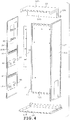
- a refrigerator 1 is mainly constructed of an insulated cabinet 2 as shown in FIG. 1 .
- the insulated cabinet 2 has in an interior thereof a refrigerating compartment 3, a vegetable compartment 4, an ice-making compartment 5, a small freezing compartment 6 and a main freezing compartment 7.
- the refrigerating compartment 3 is provided at an uppermost interior of the insulated cabinet 2.
- the vegetable compartment 4 is provided below the refrigerating compartment 3.
- the ice-making compartment 5 and the small freezing compartment 6 are provided below the vegetable compartment 4 in juxtaposition.
- the main freezing compartment 7 is provided below the ice-making compartment 5 and the small freezing compartment 6 or at a lowermost interior of the insulated cabinet 2.
- a storage compartment is constituted by the refrigerating compartment 3, the vegetable compartment 4, the ice-making compartment 5, the small freezing compartment 6 and the main freezing compartment 7.
- the refrigerating compartment 3 and the vegetable compartment 4 are storage compartments of a refrigeration temperature zone and an interior temperature of each compartment is controlled to be ranged from 0°C to 10°C, for example. Accordingly, some degree of heat insulation is required to be ensured between the refrigerating compartment 3 and the vegetable compartment 4.
- a refrigerating compartment bottom plate 8 which is a plate member and is made of a synthetic resin is provided for separating the refrigerating compartment 3 and the vegetable compartment 4 from each other.
- the ice-making compartment 5, the small freezing compartment 6 and the main freezing compartment 7 are storage compartments of a freezing temperature zone and an interior temperature of each compartment is controlled to be at or below -18°C, for example. Accordingly, an insulation partition wall 9 made of a high-performance heat insulating material is provided for separating the vegetable compartment 4 of the refrigeration temperature zone from the ice-making compartment 5 and the small freezing compartment 6 of the freezing temperature zone. The insulation partition wall 9 reduces heat leak between the vegetable compartment 4 and the ice-making compartment 5 and the small freezing compartment 6.
- the bottom plate 8 constitutes a bottom plate of the refrigerating compartment 3, so that stored articles are placed on the bottom plate 8.
- Front partition members 10, 11, 12 and 13 are provided on the front of the insulated cabinet 2 as shown in FIGS. 2 and 3 .
- the partition member 10 is located in front of the bottom plate 8, extending in the right-left direction or the lateral direction.
- the partition member 11 is located in front of the insulation partition wall 9, extending in the right-left direction or the lateral direction.
- the partition member 12 is located between the ice-making compartment 5 and the small freezing compartment 6, extending in the up-down direction.
- the partition member 13 is located between the ice-making compartment 5 and the small freezing compartment 6, and the main freezing compartment 7, extending in the right-left direction or the lateral direction.
- the refrigerating compartment 3 has two, right and left pivoted doors 16 and 15 as shown in FIG. 1 .
- the pivoted doors 15 and 16 open and close a front of the refrigerating compartment 3.
- the insulated cabinet 2 has hinge members 17a, 17b, 18a and 18b mounted on upper and middle portions of right and left ends as shown in FIGS. 2 and 3 .
- the pivoted doors 15 and 16 constitute a clamshell door caused to pivot about the hinge members 17a, 17b, 18a and 18b.
- the left pivoted door 15 is pivotally supported by a pair of upper and lower hinge members 17a and 17b.
- One of the hinge members 17a and 17b or the hinge member 17b is provided on a substantially vertically middle part of the front edge of the left sidewall insulation panel 26 constituting the insulated cabinet 2.
- the other hinge member 17a is provided on a left part of the front edge of a ceiling wall insulation panel 28 serving as a ceiling wall constituting the insulated cabinet 2.
- the hinge member 17a has a downwardly protruding hinge shaft 17aj.
- the hinge member 17b has an upwardly protruding hinge shaft 17bj.
- the left pivoted door 15 is pivotally supported by the hinge shafts 17aj and 17bj.
- the right pivoted door 16 is also pivotally supported by a pair of upper and lower hinge members 18a and 18b.
- One of the hinge members 18a and 18b or the hinge member 18b is provided on a substantially vertically middle part of the front edge of the right sidewall insulation panel 27 constituting the insulated cabinet 2.
- the other hinge member 18a is provided on a left part of the front edge of the ceiling wall insulation panel 28.
- the hinge member 18a has a downwardly protruding hinge shaft 18aj.
- the hinge member 18b has an upwardly protruding hinge shaft 18bj.
- the right pivoted door 16 is pivotally supported by the hinge shafts 18aj and 18bj.
- the vegetable compartment 4 has a front opened and closed by a pullout door 19.
- a vegetable container (not shown) is mounted on the back side or inside of the door 19.
- the ice-making compartment 5 has a front opened and closed by a pullout door 20.
- An ice-making device (not shown) is provided in the ice-making compartment 5.
- An ice storage container (not shown) is mounted on the back side or inside of the door 20.
- the small freezing compartment 6 has a front opened and closed by a pullout door 21.
- a storage container (not shown) is mounted on the back side or inside of the door 21.
- the main freezing compartment 7 has a front opened and closed by a pullout door 22.
- a storage container (not shown) is mounted on the back side or inside of the door 22.
- the vegetable compartment 4, the ice-making compartment 5, the small freezing compartment 6 and the main freezing compartment 7 opened and closed by the pullout doors 19, 20, 21 and 22 have different capacities, respectively. In this case, the capacities of the storage compartments 4, 5, 6 and 7 are rendered smaller in this order.
- the main freezing compartment 7 having the largest capacity is provided below the other compartments, that is, the vegetable compartment 4, the ice-making compartment 5 and the small freezing compartment 6.
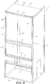
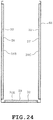
- the insulated cabinet as the insulation box is formed into the shape of a vertically long rectangular box with a front opening, by combining a plurality of insulated walls, namely, a rear wall insulation panel 25, a left sidewall insulation panel 26, a right sidewall insulation panel 27, a ceiling wall insulation panel 28 and a bottom wall insulation panel 29, as shown in FIG. 4 .
- the rear wall insulation panel 25 constitutes a rear wall of the insulated cabinet 2.
- the left sidewall insulation panel 26 constitutes a left sidewall of the insulated cabinet 2.
- the right sidewall insulation panel 27 forms a right sidewall of the insulated cabinet 2.
- the ceiling wall insulation panel 28 forms a ceiling wall of the insulated cabinet 2.
- the bottom wall insulation panel 29 constitutes a bottom wall of the insulated cabinet 2.
- the left sidewall insulation panel 26 includes an outer plate 30B, an inner plate 31B and a vacuum insulation panel 32.
- the vacuum insulation panel 32 is constructed into a plate shape and provided between the outer and inner plates 30B and 31B thereby to function as an insulating material. More specifically, the left sidewall insulation panel 26 has a construction that the vacuum insulation panel 32 is interposed between the outer and inner plates 30B and 31B.
- the outer plate 30B is a metal plate and constitutes an outer box of the insulated cabinet 2.
- the inner plate 31B is a sheet-shaped member made of synthetic resin, for example and constitutes an inner box of the insulated cabinet 2.
- a surface of the inner plate 31B will refer to an interior side face of the refrigerator, and a rear surface of the inner plate 31B will refer to a face opposed to the interior side of the refrigerator, namely, a face at the vacuum insulation panel 32 side.
- the inner plate 31B of the insulation panel 26 To the inner plate 31B of the insulation panel 26 are mounted shelf supports 40, a refrigerating compartment bottom plate mounting member 41, first rail mounting members 42, a partition wall mounting member 43, second rail mounting members 44 and a support 65, as shown in FIG. 5 .
- the inner plate 31B is bonded to the vacuum insulation panel 32 while mounted with the members 40 to 44 and the support 65.
- the vacuum insulation panel 32 has two sides, one of which is bonded to the rear surface of the inner plate 31B by an adhesive agent (not shown), as shown in FIGS. 7 , 16 and 18 .
- the other side of the vacuum insulation panel 32 is opposed to the one side thereof and bonded to an inner surface of the outer plate 30B by an adhesive agent (not shown).
- the vacuum insulation panel 32 is fixed in position while being interposed between the inner and outer plates 31B and 30B.
- the vacuum insulation panel 32 is made up of a core material 35 such as glass wool and a packaging material 38 having gas barrier properties.
- the core material 35 is put into the packaging material 38, which is then evacuated, whereby the vacuum insulation panel 32 is formed into a plate shape.
- the right sidewall insulation panel 27 also has an inner plate 31C which is located opposite the inner plate 31B of the left sidewall insulation panel 26 and provided with shelf supports 40, a refrigerating compartment bottom plate mounting member 41, first rail mounting members 42, a partition wall mounting member 43, second rail mounting members 44 and a support 65 although these components are not shown.
- the shelf supports 40 of the insulation panel 27 are opposed to the shelf supports 40 of the insulation pane 26.
- the mounting member 41 of the insulation panel 27 is opposed to the mounting member 41 of the insulation panel 26.
- the mounting members 42 of the insulation panel 27 are opposed to the mounting members 42 of the insulation panel 26.
- the mounting member 43 of the insulation panel 27 is opposed to the mounting member 43 of the insulation panel 26.
- the mounting members 44 of the insulation panel 27 are opposed to the mounting members 44 of the insulation panel 26.
- the support 65 of the insulation panel 27 is opposed to the support 65 of the insulation panel 26.
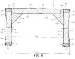
- the insulation panel 25 also has a vacuum insulation panel 32 between an outer plate 30A and an inner plate 31A in the same manner as the insulation panel 26, as shown in FIG. 6 .
- the ceiling wall insulation panel 28 has an outer plate 30D, an inner plate 31D, a vacuum insulation panel 32 and urethane foam 33 serving as an insulating material, as shown in FIG. 7 .
- the outer plate 30D is formed of a metal plate.
- the inner plate 31D is formed of a synthetic-resin integral molded product.
- the vacuum insulation panel 32 is fixed to a back side of the inner plate 31D by an adhesive or the like.
- the urethane foam 33 fills a gap between the vacuum insulation panel 32 and the outer plate 30D.
- the vacuum insulation panel 32 has a lower heat conductivity and a higher insulation performance than the urethane foam 33.
- the insulation panel 28 has an equipment compartment 28k which is defined at a rear upper interior so as to be recessed into an L-shape as shown in FIG. 1 .
- a compressor 36 of a refrigeration cycle is housed in the equipment compartment 28k.
- the bottom wall insulation panel 29 also has a vacuum insulation panel and urethane foam between the outer plate 30E and the inner plate 31E in the same manner as the insulation panel 28 although the insulation panel 29 has a shape differing from that of the insulation panel 28.
- the outer plates 30A to 30E constitute an outer surface of the insulated cabinet 2, namely, a cabinet outer surface.
- the inner plates 31A and 31B constitute an inner surface of the interior.
- the rear wall insulation panel 25 and the left sidewall insulation panel 26 are connected to each other by a fixture 23A and screws (not shown) and the like at the left rear corner as shown in FIG. 6 .
- the insulation panel 25 and the insulation panel 27 are also connected to each other by a fixture 23B similar to the fixture 23A and screws and the like at the right rear corner.
- Each of these corners is provided with insulating materials 34a to 34c such as urethane foam, soft tape or sponge rubber foam tape.
- the insulation panel 28 and the insulation panel 29 are also connected to the insulation panels 25 and 27 appropriately. Further, fronts of the insulation panels 26 and 27 are connected to each other by front partition members 10 to 13.
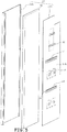
- the insulated cabinet 2 has a front opening edge including right and left front edges, namely, front edges of the insulation panels 26 and 27, as shown in FIGS. 8 and 9 .
- the front edges of the insulation panels 26 and 27 are reinforced by vertical reinforcing members 51.
- an upper front edge and right and left front edges are reinforced by an upper reinforcing member 52. Note that the members 40 to 44 and 65 are eliminated in FIGS. 8 and 9 for the sake of avoiding drawing complications.
- the vertical reinforcing member 51 has a vertical dimension that is set to be substantially equal to a vertical dimension of the left sidewall insulation panel 26.
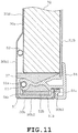
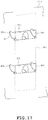
- the vertical reinforcing member 51 includes an outer plate 51a, a middle plate 51b and an inner plate 51c and has an open rear thereby to be formed into the shape of a groove, as shown in FIG. 11 .
- the vertical reinforcing member 51 has portions, that is, connections to the front partition members 10, 11 and 13.
- the inner plates 51c are cut off at the connections, whereby these portions are formed into an L-shape, as shown in FIGS. 13 and 14 .
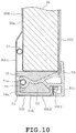
- the vertical reinforcing member 51 is inserted into the front edge of the left sidewall insulation panel 26 from above or from below as shown in FIG. 10 .
- a bent portion 30b of the outer plate 30B departs from a front end of the vacuum insulation panel 32 at the front end of the insulation panel 26, coming around to front. More specifically, the bent portion 30b of the outer plate 30B includes an outer protuberance 30b1, a middle portion 30b2 and an inner extending portion 30b3.
- the outer protuberance 30b1 protrudes slightly outward relative to the bent portion 30b thereby to be spaced from the vacuum insulation panel 32.
- the middle portion 30b2 is bent inward at the front end of the outer protuberance 30b1.
- the inner extending portion 30b3 is formed into an L-shape that is bent rearward relative to the inner end of the middle portion 30b2.
- the bent portion 30b of the outer plate 30B is constructed into a groove shape with an open rear.
- the vertical reinforcing member 51 is inserted so as to be fitted with a groove-shaped inside of the bent portion 30b, being connected to the outer plate 30B by adhesive agent or screwing. Further, the vertical reinforcing member 51 is spaced from the inner plate 31B. More specifically, the vertical reinforcing member 51 is unconnected with the inner plate 31B.
- a radiation pipe 53 of the refrigeration cycle is provided between the vacuum insulation panel 32 and the outer protuberance 30b1 in FIG. 10 .
- a synthetic resin sealing member 54 is provided between the inner plate 31B and the bent portion 30b of the outer plate 30B to seal a gap therebetween.
- the sealing member 54 has a pipe holder 54a which fixes a dew-proofing pipe 55 preventing dew condensation on the front of the insulated cabinet 2.
- the dew-proofing pipe 55 is constituted by a part of the radiation pipe of the refrigeration cycle.
- Other radiation pipes 53 are also provided in the rears of the right and left sidewall insulation panels 27 and 26 respectively, as shown in FIG. 6 .
- Insulating materials 37 comprising soft tape are provided in the front 30a of the outer plate 30B.
- the upper reinforcing member 52 includes a middle plate 52a, a left plate 52b and a right plate 52c as shown in FIGS. 8 and 9 .
- the right and left plates 52c and 52b are constructed to droop perpendicular to both ends of the middle plate 52a respectively.
- the right and left plates 52c and 52b are inserted into the fronts of the right and left sidewall insulation panels 27 and 26 from above respectively.
- the right and left plates 52c and 52b are fixed to the front edge of the insulation panel 28 while being in contact with an inner surface of the vertical reinforcing member 51, as shown in FIG. 11 .
- the middle plate 52a is thus fixed to the front edge of the insulation panel 28.
- the compressor 36 which relatively has a larger weight, is provided in the rear of the insulated cabinet 2.
- the vertical reinforcing member 51 and the upper reinforcing member 52 are provided near the front of the insulated cabinet 2, that is, in front of the compressor 36. Accordingly, the vertical reinforcing member 51 and the upper reinforcing member 52 contribute to equalization of weight in the front-back direction in the insulated cabinet 2.
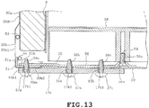
- the hinge member 17b is provided on a connection between the left sidewall insulation panel 26 of the insulated cabinet 2 and the front partition member 10, as shown in FIGS. 12 and 13 .
- the hinge member 18b is provided on a connection between the insulation panel 27 and the front partition member 10 as shown in FIG. 2 . Since the hinge members 17b and 18b are mounted in the relationship of bilateral symmetry, only the hinge member 17b will be described.
- the inner plate 51c of the vertical reinforcing member 51 is cut in the connection to the front partition member 10 thereby to be formed into an L-shape as shown in FIG. 10 .
- the inner extending portion 30b3 as shown in FIG. 10 is also cut in the same manner.
- a reinforcement backing member 56 is provided so as to extend over a rear of the left vertical reinforcing member 51 and a rear of the front partition member 10 as shown in FIG. 13 .
- the hinge member 17b extends over a front of the left sidewall insulation panel 26 and a front of the front partition member 10. More specifically, the hinge member 17b is formed with, for example, three screw passing holes 17bl, 17b2 and 17b3. Further, the middle portion 30b2 of the outer plate 30B is formed with a screw passing hole 30m. The middle plate 51b of the vertical reinforcing member 51 is formed with a screw passing hole 51b1.
- the reinforcement backing member 56 is formed with three screwing holes 56a, 56b and 56c, which include respective female threads and respective tapping holes.
- the reinforcement backing member 56 is further formed with a generally dish-shaped recess 56d having a bottom through which a screw passing hole 56e is formed.
- the front partition member 10 is formed with screw passing holes 10a and 10b.
- the reinforcement backing member 56 is placed on the back of the vertical reinforcing member 51 and the front partition member 10.
- the hinge member 17b is then disposed on the front of the middle portion 30b2 of the outer plate 30B and the front of the front partition member 10.
- a screw 57a is passed through the screw passing holes 17b1, 30m and 51b1 of the hinge member 17b, the outer plate 30B and the vertical reinforcing member 51.
- the screw 57a is further screwed into the screw hole 56a of the reinforcement backing member 56.
- the screw 57b is passed through the screw passing holes 17b2 and 10a of the hinge member 17b2 and the front partition member 10.
- the screw 57b is further screwed into the screw hole 56b of the reinforcement backing member 56.
- the screw 57c is passed through the screw passing holes 17b3 and 10b of the hinge member 17b and the front partition member 10.
- the screw 57c is then screwed into the screw hole 56c of the reinforcement backing member 56.
- the hinge member 17b is thus fixed to the connection between the front partition member 10 and the left sidewall insulation panel 26.
- a part of the hinge member 17b is fixed to the vertical reinforcing member 51.
- the part of the hinge member 17b is connected via a reinforcement connecting member 56 to the vertical reinforcing member 51.
- the upper hinge members 17a and 18a are fixed by screws to right and left corners of the upper reinforcing member 52, that is, the vicinity of the connection between the middle plate 52a and the right and left plates 52c and 52b at the upper surface side of the ceiling wall insulation panel 28.
- a partition rear cover 58 made of a synthetic resin is provided on the back of the front partition member 10.
- the partition rear cover 58 is mounted to the reinforcement backing member 56 before the front partition member 10 is mounted to the reinforcement backing member 56.
- the reinforcement backing member 56 is formed with the screw passing hole 56e, through which a countersunk screw 59 is passed.
- the countersunk screw 59 passed through the screw passing hole 56e is screwed into the partition rear cover 58 disposed on the back of the reinforcement backing member 56.
- the front partition member 10 is subsequently mounted to the reinforcement backing member 56.
- the partition rear cover 58 is fixed via the reinforcement backing member 56 to the front partition member 10.
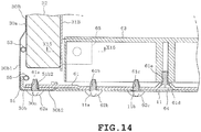
- connection between the front partition member 11 and the left sidewall insulation panel 26 will be described with reference to FIGS. 14 and 15 .
- the connections between the front partition member 11 and the right and left sidewall insulation panels 27 and 26 are bilaterally symmetric.
- the vertical reinforcing member 51 is formed in a connection thereof with the front partition member 11 into an L-shape by cutting a part of the inner plate 51c as shown in FIG. 10 .
- the outer plate 30B has a connection thereof with the front partition member 11.
- the inner extending portion 30b3 in the connection is also cut as shown in FIG. 10 .
- a reinforcement backing member 61 is provided so as to extend over the rears of the vertical reinforcing member 51 and the front partition member 11.
- the front partition member 11 is connected via the reinforcement backing member 61 to the vertical reinforcing member 51.
- the middle portion 30b2 of the outer plate 30B is formed with a screw passing hole 30n.
- the middle plate 51b of the vertical reinforcing member 51 is formed with a screw passing hole 51b2.
- the reinforcement backing member 61 is further formed with three screw holes 61a, 61b and 61c and a generally dish-shaped recess 61d, which has a bottom through which a screw passing hole 61e is formed.
- the front partition member 11 is formed with screw passing holes 11a and 11b.
- the reinforcement backing member 61 is firstly disposed behind the vertical reinforcing member 51 and the front partition member 11.
- a screw 62a is passed through the screw passing holes 30n and 51b2 of the outer plate 30B and the vertical reinforcing member 51 in turn.
- the screw 62a is then screwed into the screw hole 61a of the reinforcement backing member 61.
- a screw 62b is passed through the screw passing hole 11a of the front partition member 11, and a screw 62c is passed through the screw passing hole 11b of the front partition member 11, in the same manner.
- the screw 62b is then screwed into the screw hole 61b of the reinforcement backing member 61, and the screw 62c is then screwed into the screw hole 61c of the reinforcement backing member 61.
- the front partition member 11 and the vertical reinforcing member 51 are fixed to each other by the reinforcement backing member 61.
- a partition rear cover 63 made of a synthetic resin is provided behind the front partition member 11.
- the partition rear cover 63 is disposed on the reinforcement backing member 61 before the front partition member 11 is mounted to the left sidewall insulation panel 26.
- the reinforcement backing member 61 is formed with the screw passing hole 61e through which a countersunk screw 64 is passed.
- the countersunk screw 64 passed through the screw passing hole 61e is screwed into the partition rear cover 63 disposed behind the reinforcement backing member 61.
- the front partition member 11 is mounted to the reinforcement backing member 61.
- the partition rear cover 63 is fixed via the reinforcement backing member 61 to the front partition member 11.
- the partition rear cover 63 is supported by a support 65 provided on the left sidewall insulation panel 26.
- the support 65 is formed of a synthetic resin, for example and has a protruding portion 65a and extending portions 65b and 65c integrally formed therewith, as shown in FIG. 15 .
- the protruding portion 65a is formed into a rectangular block shape and has a screw passing hole 65d and a counterbore 65e.
- the screw passing hole 65d is formed so as to vertically extend through the protruding portion 65a into a circular shape.
- the screw passing hole 65d is formed into the shape of an elongated hole which is long in the right-left direction.
- the counter bore 65e has an inner diameter larger than an inner diameter of the screw passing hole 65d and is formed so as to be recessed upwardly from the underside of the protruding portion 65a to a middle part of the thickness of the protruding portion 65a.
- the extending portions 65b and 65c are each formed into the shape of a rectangular plate extending vertically from a horizontal end of the protruding portion 65a, in this case, the end at the inner plate 31B side.
- Each one of the extending portions 65b and 65c has a horizontal thickness that is smaller than a vertical thickness of the protruding portion 65a.
- the inner plate 31B is formed with a hole 31k, which is formed so as to extend through the inner plate 31B into a rectangular shape slightly larger than the protruding portion 65a and smaller than outlines of the extending portions 65b and 65c.
- the support 65 is provided on the inner plate 31B when the left sidewall insulation panel 26 is assembled.
- the protruding portion 65a of the support 65 is passed through the hole 31k of the inner plate 31B outward from inside the left sidewall insulation panel 26, that is, to the interior side from the vacuum insulation panel 32 side.
- Adhesive is provided between the extending portions 65b and 65c and the inner plate 31B and between the extending portions 65b and 65c and the vacuum insulation panel 26.
- the support 65 is bonded to the vacuum insulation panel 32 thereby to be fixed while the extending portions 65b and 65c are held between the inner plate 31B and the vacuum insulation panel 32.
- the partition rear cover 63 has a supported portion 63a.
- the supported portion 63a is formed by recessing a lower part of the cover 63 corresponding to the support 65 upwardly from below.
- the supported portion 63a has a screw hole 63b formed to extend upward from the lower side.
- the protruding portion 65a of the support 65 is inserted into the supported portion 63a.
- the screw 66 having passed through the screw passing hole 65d is screwed into the screw hole 63b.
- the partition rear cover 63 is fixed to the support 65 by the screw 66 while the supported portion 63a provided on the lower part thereof is supported by the support 65 and fixed to the support 65 by a screw 66.
- the partition rear cover 63 has right and left side dimensions which are set so that a gap G is defined between the right and left insulation panels 27 and 26. More specifically, the right and left insulation panels 27 and 26 are assembled with reference to an outer width Hs of the insulated cabinet 2 shown in FIG. 6 . In this case, variations in the thicknesses of the right and left sidewall insulation panels 27 and 26 are absorbed by changing an inner width Hu of the insulated cabinet 2. As a result, the variations in the thicknesses of the panels 27 and 26 caused during the manufacturing process are tolerated to some degree.
- the inner width Hu of the insulated cabinet 2 becomes minimum when the thicknesses of the right and left sidewall insulation panels 27 and 26 are increased to respective maximum values in tolerable ranges.
- the right and left side dimensions of the partition rear cover 63 are set so that the gap G is defined even when the inner width Hu of the insulated cabinet 2 is minimum.
- the gap G is small.
- the gap G may be filled with an insulating material such as soft tape.
- shelf supports 40 provided on the left sidewall insulation panel 26, a mounting member 41 for a refrigerating compartment bottom plate, first rail mounting members 42, partition wall mounting members 43 and second rail mounting members 44.
- Each shelf support 40 has a plurality of protrusions 40a and 40b and an extending portion 40c as shown in FIGS. 16 and 17 .
- the extending portion 40c is formed into a vertically long rectangular plate shape.
- the protrusions 40a and 40b are each formed into a hook shape directed upward and protrude to the interior side from right and left ends of the extending portion 40c.
- the right and left protrusions 40a are paired, and the right and left protrusions 40b are also paired.
- the protrusions 40b are located below the protrusions 40a.
- the shelf supports 40 are formed by punching the protrusions 40a and 40b and the extending portion 40c from a metal plate and thereafter bending the protrusions 40a and 40b.
- a shelf (not shown) is placed on the hook-shaped protrusions 40a and 40b of the shelf support 40.
- Holes 31a and 31b are formed through the inner plate 31B so as to be spaced away from each other in the up-down direction.
- the holes 31a and 31b are formed into a rectangular shape such that the protrusions 40a and 40b are insertable into the holes 31a and 31b respectively.
- the protrusions 40a and 40b are inserted into the holes 31a and 31b from the rear side of the inner plate 31B, protruding to the front side of the inner plate 31B.
- the extending portion 40c is bonded to peripheral portions of the holes 31a and 31b in the rear of the inner plate 31B.
- the inner plate 31B provided with the extending portion 40c has the rear surface bonded to the vacuum insulation panel 32 as shown in FIG. 5 .
- the shelf support 40 is thus fixed while being held between the inner plate 31B and the vacuum insulation panel 32 as shown in FIG. 16 .
- the refrigerating compartment bottom plate mounting member 41 also serves as reinforcing member mounting portions and are provided below the refrigerating compartment bottom plate 8 as shown in FIG. 3 .
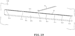
- the mounting member 41 is formed into an elongated shape, extending in the front-back direction as a whole, as shown in FIGS. 18 and 19 .
- the mounting member 41 has a protrusion 41a, an extending portion 41b and an engagement portion 41c all of which are formed integrally therewith.
- the protrusion 41a, the extending portion 41b and the engagement portion 41c are formed together by bending a metal plate.
- the extending portion 41b is formed into the shape of a rectangular plate long in the front-back direction and is parallel to the inner plate 31B, that is, substantially vertical.
- the protrusion 41a is formed by bending an upper edge of the extending portion 41b to the interior side into a substantially horizontal state.
- the engagement portion 41c is formed by bending a lower edge of the extending portion 41b to the interior side into a substantially horizontal state and further by bending an interior side end thereof downward into a substantially vertical state.
- the mounting member 41 includes a part extending from the protrusion 41a to the extending portion 41b, and the part has an L-shaped longitudinal section. More specifically, the protrusion 41a and the extending portion 41b are continuous such that the longitudinal section is L-shaped. Furthermore, the mounting member 41 has a longitudinal section which is groove-shaped with its interior side being open.
- the protrusion 41a is formed with a plurality of arrangement holes 41d and a plurality of screw passing holes 41e as shown in FIG. 19 .
- the arrangement holes 41d are slit-like connecting holes extending lengthwise with respect to the protrusion 41a, that is, in the front-back direction.
- the screw passing holes 41e are connecting holes comprising holes elongated in the right-left direction.
- the inner plate 31B is formed with holes 31d and 31e as shown in FIG. 18 . Each of the holes 31d and 31e is formed into the shape of a slit.
- the protrusion 41a is inserted into the hole 31d from the rear of the inner plate 31B.
- the engagement portion 41c is inserted into the hole 31e from the rear of the inner plate 31B.
- the extending portion 41b is bonded to the rear surface of the inner plate 31B and the vacuum insulation panel 32 while being held between the rear surface of the inner plate 31B and the vacuum insulation panel 32.
- the mounting strength of the mounting member 41 to the left sidewall insulation panel 26 is improved by engaging the engagement portion 41c with the hole 31e.
- the mounting members 41 are provided so as to be opposed to the right and left inner plates 31C and 31B thereby to be paired with the inner plates 31C and 31B respectively.
- a bridge-shaped reinforcing member 71 has one end and the other end both connected to the mounting members 41 respectively.
- the reinforcing member 71 is formed by upwardly bending both ends of a rectangular metal plate long in the right-left direction.
- the ends of the reinforcing member 71 are provided on front-back central portions of the mounting members 41 respectively. Screws 72 are passed, from below, through the screw passing holes 41e in the front-back central portions of the mounting members 41 respectively.
- the screws 72 are screwed into the reinforcing members 71 respectively, whereby both ends of the reinforcing members 71 are fixed to the right and left mounting members 41.
- the right and left mounting members 41 are conned to each other by the reinforcing members 71.
- each screw passing hole 41e is formed into a hole elongated in the right-left direction.
- connecting positions of the reinforcing members 71 to the mounting members 41 are adjustable. Accordingly, the reinforcing members 71 can be mounted to the mounting members 41 desirably respectively even when thicknesses of the right and left sidewall insulation panels 26 and 27 vary.
- the right and left sidewall insulation panels 26 and 27 are assembled on the basis of the outer widths Hs of the insulated cabinet 2 shown in FIG. 6 .
- the variation in the thicknesses of the insulation panels 26 and 27 are absorbed by changing the inner width Hu of the insulated cabinet 2.
- the screw passing hole 41e responds to the changes in the width Hu of the insulated cabinet 2, the screw passing hole 41e is formed into the shape of a hole larger than a diameter of the screw 72.
- the mounting position of the reinforcing member 71 relative to the mounting member 41 is adjustable according to the changes in the inner width Hu of the insulated cabinet 2.
- the reinforcing member 71 is then connected to the mounting members 41 strongly after the mounting positions thereof to the right and left mounting members 41 have been adjusted. This can effectively reduce deformation of the insulation panels 26 and 27 in the curvature direction.
- the refrigerating compartment bottom plate 8 has engagement protrusions (not shown) protruding downward from the underside.
- the bottom plate 8 is disposed by fitting the engagement protrusions into the arrangement holes 41d from above the mounting members 41.
- the compressor 36 which is relatively heavier is provided near the rear of the insulated cabinet 2.
- the reinforcing member 71 is provided near the front of the insulated cabinet 2. Accordingly, the reinforcing member 71 contributes to equalization in the weight of the insulated cabinet 2 in the front-back direction.
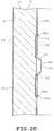
- Each of the mounting members 42 is made of a metal plate and has a protrusion 42a, an extending portion 42b, an upper engagement portion and a lower engagement portion 42d, all of which are formed integrally with each mounter member 42, for example.
- the protrusion 42a protrudes to the interior side from the inner plate 31B and is formed into a substantially circular shape with the interior side bottom being closed. In this case, the protrusion 42a is formed into a cylindrical shape approximate to a cup-shape.
- the extending portion 42b is formed into the shape of a plate extending in the up-down direction from a hem of the protrusion 42a.
- the upper engagement portion 42c is provided on a central portion of the extending portion 22b in the front-back direction.
- the upper engagement portion 42c protrudes upward into an L-shape. More specifically, the upper engagement portion 42c is bent so as to protrude to the interior side from an upper end of the extending portion 42b, and the protruding distal end of the upper engagement portion 42c is bent upward.
- Two lower engagement portions 42d are provided on a lower part of the extending portion so as to be juxtaposed in the front-back direction. The lower engagement portion 42d is bent so as to protrude to the interior side from a lower end of the extending portion 42b.
- the protrusion 42a is formed with a screw hole 42e.
- the inner plate 31B is formed with a circular through hole 31f.
- the protrusion 42a of the first rail mounting member 42 is inserted into the hole 31f from the rear side of the inner plate 31B, protruding to the interior side from the hole 31f.
- the inner plate 31B is formed with an upper engagement hole 31g and a lower engagement hole 31h.
- Each of the upper and lower engagement holes 31g and 31h is formed through the inner plate 31B into the shape of a slit which is long in the front-back direction.
- a single upper engagement hole 31g is formed above the hole 31f.
- Two lower engagement holes 31h are formed below the hole 31f so as to be juxtaposed in the front-back direction.
- the first rail mounting member 42 will be mounted to the inner plate 31B as follows. Firstly, the upper engagement portion 42c of the first rail mounting member 42 is inserted into the upper engagement hole 31g from the rear side of the inner plate 31B. The protrusion 42a is inserted into the hole 31f and the lower engagement portion 42d is inserted into the lower engagement hole 31h while the first rail mounting member 42 is rotated about the upper engagement portion 42c to the inner plate 31B side. In this case, an adhesive agent is applied between the extending portion 42b and the rear surface of the inner plate 31B, so that the extending portion 42b is bonded to the rear surface of the inner plate 31B. Further, the extending portion 42b is also bonded to the vacuum insulation panel 32 by an adhesive agent or the like. The extending portion 42b is thus fixed to the inner plate 31B and the vacuum insulation panel 32 by the adhesive agent while being held between the inner plate 31B and the vacuum insulation panel 32.
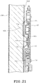
- a rail 45 is mounted to the first rail mounting member 42 as shown in FIG. 21 .
- the rail 45 extends in the front-rear direction to guide the front-rear movement of a support frame (not shown) which is to be mounted on the rear of the door 19 of the vegetable compartment 4.
- the rail 45 is fixed by screwing a screw into the screw hole 42e formed in the protrusion 42a of the first rail mounting member 42.
- the partition wall mounting member 43 also serves as a reinforcing member mounting portion and is provided near the insulation partition wall 9, in this case, under the insulation partition wall 9 so as to extend in the front-back direction, as shown in FIG. 3 .
- the partition wall mounting member 43 will be described with reference to FIGS. 22 and 23 .
- the partition wall mounting member 43 is constructed in the same manner as the refrigerating compartment bottom plate mounting member 41. More specifically, the partition wall mounting member 43 is formed of, for example, a metal plate into an elongated shape extending in the front-back direction as a whole.
- the partition wall mounting member 43 has a protrusion 43a, an extending portion 43b and an engagement portion 43c.
- the protrusion 43a, the extending portion 43b and the engagement portion 43c are formed integrally with the mounting member 43 by bending the metal plate, for example.
- the extending portion 43b is formed into the shape of a rectangular plate which is parallel to the inner plate 31B, that is, substantially vertical and is long in the front-back direction.
- the protrusion 43a is formed by bending an upper edge of the extending portion 43b substantially horizontally to the interior side.
- the engagement portion 43c is formed by downwardly bending a lower edge of the extending portion 43b substantially horizontally.
- a part of the mounting member 43 from the protrusion 43a to the extending portion 43b has an L-shaped longitudinal section. More specifically, the protrusion 43a and the extending portion 43b are continuous such that the longitudinal sections are L-shaped. Further, the mounting member 43 has a longitudinal section that is groove-shaped and has an open interior side as a whole.
- the protrusion 43a is formed with a plurality of arrangement holes 43d.
- the arrangement holes 43d are slit-like connecting holes extending lengthwise with respect to the protrusion 43a, that is, in the front-back direction.
- the inner plate 31B is formed with holes 31i and 31j both of which are also formed into a slit-shape.
- the protrusion 43a is inserted into the hole 31i from the rear side of the inner plate 31B.
- the engagement portion 43c is inserted into the hole 31j from the rear side of the inner plate 31B.
- the extending portion 43b of the mounting member 43 is bonded to the rear surface of the inner plate 31B and the vacuum insulation panel 32 while being held therebetween. In this case, the engagement portion 43c of the mounting member 43 is in engagement with the hole 31j. This improves the mounting strength of the mounting member 43 to the insulation panel 26.
- the insulation partition wall 9 has an insulating material 9b, such as urethane foam, provided in the inside of the outer casing 9a as shown in FIG. 23 .
- the outer casing 9a has protrusions 9c formed integrally therewith.
- the protrusions 9c are formed into a columnar shape and protrude downward from the undersides of right and left ends of the outer casing 9a.
- FIG. 23 shows only the protrusion 9c of the left end.
- the protrusions 9c are inserted into the arrangement holes 43d of the mounting members 43 mounted on the insulation panels 26 and 27 to be engaged with the arrangement holes 43d, respectively.
- the insulation partition wall 9 is provided in the insulated cabinet 2 so as to partition the interior thereof vertically.
- the insulation partition wall 9 also serves as a bridge-shaped reinforcing member.
- the insulation partition wall 9 has a horizontal dimension which is set so as to cause a gap G in view of the variations in the thickness of the right and left insulation panels 26 and 27, in the same manner as the partition rear cover 63. Also, for the same reason, each arrangement hole 43d has an inner diameter which is set to be slightly larger than an outer diameter of each protrusion 9c of the insulation partition wall 9. As a result, the connecting position of the insulation partition wall 9 to the mounting member 43 is adjustable.
- Two second rail mounting members 44 are provided on each of right and left walls of the main freezing compartment 7 so as to be disposed in the front-back direction, as shown in FIG. 3 .
- Each second rail mounting member 44 has the same construction as each first rail mounting member 42 and is mounted on the inner plate 31B in the same manner as each first rail mounting member 42. It is desirable to pack an insulating material such as a soft tape in the gap G.
- the insulated cabinet 2 has the vacuum insulation panels 32 between the outer plates 30A to 30E constituting the outside surface and the inner plates 31A to 31E constituting the inner surface.
- the vacuum insulation panels 32 have a higher insulation performance than the foam urethane 33. Accordingly, the peripheral wall of the insulated cabinet 2 can be rendered thinner.
- the strength of the opening side edges of the right and left sidewalls tends to be weaker than the other parts of the right and left sidewalls and are relatively easy to deform when subjected to external force.
- the influence of external force applied to the front opening ends of the right and left sidewall insulation panels 26 and 27 tends to become larger in the insulated cabinet with a thinned peripheral wall by the use of the vacuum insulation panel 32 as in the embodiment. In this case, for example, when the load of the pivoted door or the like is applied to the front opening ends of the right and left sidewall insulation panels 27 and 26, there is a possibility that the insulation panels would be deformed.
- the insulated cabinet of the embodiment has the vertical reinforcing members 51.
- the reinforcing members 51 are provided on the front opening edges of the right and left sidewall insulation panels 27 and 26 serving as the right and left sidewalls. According to this, the strength of the right and left sidewall insulation panels 27 and 26 of the insulated cabinet 2 can be improved. Accordingly, deformation of the right and left sidewall insulation panels 27 and 26 can be reduced even when external force is applied to the front opening ends of the right and left sidewall insulation panels 27 and 26.
- the deformation of the right and left sidewall insulation panels 27 and 26 in the curvature direction is reduced by the refrigerating compartment bottom plate mounting member 41 and the bridge-shaped reinforcing member 71.
- This is effective particularly in the case where the right and left sidewall insulation panels 27 and 26 have respective thicknesses which are not more than 35 mm.
- the vacuum insulation panel 32 has a thickness of 20 mm, and the sum total of the thicknesses of the right and left sidewall insulation panels 27 and 26 is 1.5 mm. Accordingly, an entire thickness of the insulation panels 26 and 27 is 21. 5 mm, which value is not more than the further effective value of 25 mm.
- the left sidewall insulation panel 26 has the bent portion 30b.
- the bent portion 30b is formed by bending the opening side end of the insulated cabinet 2 of the outer plate 30B to the interior side and further bending the distal portion rearward.
- the vertical reinforcing member 51 is provided along the inside of the bent portion 30b, that is, a surface at the vacuum insulation panel 32 side. According to this, the bent portion 30b is caused to contribute to an improvement in the strength of the front end of the left sidewall insulation panel 26, in addition to the vertical reinforcing member 51. Accordingly, the left sidewall insulation panel 26 is further reinforced, whereby the deformation due to external force can be reduced.
- the right sidewall insulation panel 27 is also further reinforced in the same manner as the left sidewall insulation panel 26.
- the vertical reinforcing member 51 is not joined to the inner plate 31B in the left sidewall insulation panel 26 or is disconnected from the inner plate 31B.
- the vertical reinforcing member 51 is relatively strong against external force. Accordingly, for example, when the outer plate 30B and the inner plate 31B are connected together by the vertical reinforcing member 51, the vertical reinforcing member 51 limits movement of the outer and inner plates 30B and 31b in the direction of the thickness of the vacuum insulation panel 32 or in a direction such that the outer and inner plates 30B and 31B depart from each other. In this case, even when the thicknesses of the vacuum insulation panels 32 vary during manufacture of the vacuum insulation panels 32, the distance between the outer and inner plates 30B and 31B cannot follow the variations in the thickness of the vacuum insulation panel 32.
- the outer and inner plates 30B and 31B are joined to each other via the vacuum insulation panel 32 but is not joined to each other via the vertical reinforcing member 51.
- the outer and inner plates 30B and 31B are allowed to be relatively moved in the right-left direction by the changes in the thickness of the vacuum insulation panel 32, that is, in the direction of thickness of the vacuum insulation panel 32. More specifically, when the thickness of the vacuum insulation panel 32 varies, the outer and inner plates 30B and 31B can be relatively moved in the direction of thickness of the vacuum insulation panel 32. Hence, the distance between the outer and inner plates 30B and 31B can follow the variations in the thickness of the vacuum insulation panel 32.
- One 17b of the paired hinge members 17a and 17b supporting the pivoted door 15 is provided on the left sidewall insulation panel 26, and the other hinge member 17a is provided on the ceiling wall insulation panel 28.
- a part of the hinge member 17b is fixed to the vertical reinforcing member 51. Load due to the weight of the pivoted door 15 and load applied to the hinge member 17b by the operation during the opening and the closing are large. However, the hinge member 17b is supported by the vertical reinforcing member 51 having a relatively higher strength. This reduces movement of the mounting position of the hinge member 17b or tilt of the hinge shaft 17bj by the load. Accordingly, desirable pivoting of the pivoted door 15 can be maintained.
- the tilt of the pivoted door 15 can also be reduced. This can also reduce application of excessive force to the front end of the left sidewall insulation panel 26 due to the tilt of the pivoted door 15. As a result, deformation of a part of the left sidewall insulation panel 26 corresponding to the hinge member 17b can be reduced.
- the other hinge members 18a and 17a are provided on the right and left corners in the ceiling wall insulation panel 28. This provides a relatively strong structure against load by the pivoted doors 15 and 16.
- the hinge members 17a and 18a may be provided on the bottom wall insulation panel 29.
- the reinforcement backing member 56 is provided on the back of the vertical reinforcing member 51. A part of the hinge member 17b is fixed via the reinforcement backing member 56 to the vertical reinforcing member 51. More specifically, the hinge member 17b is supported by the vertical reinforcing member 51 and the reinforcement backing member 56. This can effectively reduce the lowering of the mounting position of the hinge member 17b and downward tilt of the hinge member 17b. The same can be applied to the hinge member 18b.
- the refrigerator 1 includes the vegetable compartment 4, the ice-making compartment 5, the small freezing compartment 6 and the main freezing compartment 7 as a plurality of storage compartments opened and closed by the pullout doors 19, 20, 21 and 22.
- the main freezing compartment having a largest capacity is provided lower than the other storage compartments, namely, the vegetable compartment 4, the ice-making compartment 5 and the small freezing compartment 6. According to this, deformation of the insulated cabinet 2 by the load of the pullout doors can be reduced. More specifically, the pullout doors 19, 20, 21 and 22 have respective storage containers (not shown).
- the doors 19 and 22 are supported by the rail 45 so as be drawn forth and back, as shown in FIG. 21 .
- a rail for the doors 20 and 21 is not shown.
- the rail 45 and the rail (not shown) supporting the doors 20 and 21 are provided on the right and left sidewall insulation panels 26 and 27.
- load due to the weight of the doors 19 to 22 including the storage containers is applied via the rail 45 and the like to the right and left sidewall insulation panels 26 and 27 of the insulated cabinet 2.
- the load due to the weight of the doors 19 to 22 including the storage containers becomes larger as the capacities of the storage compartments are increased.
- the main freezing compartment having a large capacity is provided lower than the other storage compartments, namely, the vegetable compartment 4, the ice-making compartment 5 and the small freezing compartment 6.
- the weight of the door 22 provided on the main freezing compartment 7 and the storage container can be received by the right and left sidewall insulation panel 26 near the bottom wall insulation panel 29.
- the right and left sidewall insulation panels 26 and 27 include respective portions located near the bottom wall insulation panel 29. These portions are connected to the bottom wall insulation panel 29. Accordingly, these portions are hard to deform as compared with the other portions of the right and left sidewall insulation panels 26 and 27.
- the compressor 36 is provided on the rear part of the ceiling wall insulation panel 28 serving as the upper wall of the insulated cabinet 2.
- the vertical reinforcing member 51 is provided in front of the compressor 36. According to this, the vertical reinforcing member 51 contributes to equalization in the weight of the insulated cabinet 2 in the front-back direction.
- the pivoted doors may open and close the whole opening of the insulated cabinet 2.
- one of the paired hinge members supporting each pivoted door can be provided on the ceiling wall of the insulated cabinet 2, namely, the ceiling wall insulation panel 28 and the other hinge member can be provided on the bottom wall of the insulated cabinet 2, namely, the bottom wall insulation panel 29.
- the outer box of the insulated cabinet 2 is constructed by combining a plurality of divided outer plates, in this case, the outer plate 30A of the rear wall insulation panel 25, the outer plate 30B of the left sidewall insulation panel 26, the outer plate 30C of the right sidewall insulation panel 27, the outer plate 30D of the ceiling wall insulation panel 28 and the outer plate 30E of the bottom wall insulation panel 29.
- outer plates constituting the outer box of the insulated cabinet 2 includes a part corresponding to the left sidewall insulation panel 26, the right sidewall insulation panel 27 and the bottom wall insulation panel 29. This part of the outer plates is constituted by a single outer plate 85.
- the insulated cabinet 2 is divided into the rear, right and left, and upper and lower walls, that is, the rear wall insulation panel 25, the left sidewall insulation panel 26, the right sidewall insulation panel 27, the ceiling wall insulation panel 28 and the bottom wall insulation panel 29.
- the rear wall and the upper wall may be formed into a single wall, and the right and left sidewalls may be connected to the single wall.
- a dividing manner may be changed appropriately.
- the vacuum insulation panel may have a flat shape corresponding to the walls or may be bent so as to cover a plurality of walls.
- a vacuum insulation panel, urethane foam or the like may be disposed between outer and inner plates of each wall constituting the insulated cabinet.
- urethane foam may be used as an insulation material of the insulated cabinet, instead of the vacuum insulation panel.
- the refrigerator of each of the above-described embodiments includes the insulated cabinet having the opening in the front and constructed into a box shape and having the insulation panel between the outer plate constituting the external surface and the inner plate constituting the interior surface.
- the vertical reinforcing members are provided on the opening side edges of the right and left sidewalls constituting the insulated cabinet respectively. According to this, the deformation of the right and left sidewalls of the insulated cabinet can be reduced.
Description
- Embodiments of the present invention relate to a refrigerator.
- An insulated cabinet serving as a body of a refrigerator includes an outer box, an inner box and an insulating material provided between the outer and inner boxes and is constructed into a generally box shape as a whole . An insulation panel having a high insulation performance, such as vacuum insulation panel, has been recently used as an insulating material for the insulated cabinet. Since the insulation performance of the insulated cabinet is thus improved, a peripheral wall of the insulated cabinet can be rendered thinner.
- The insulated cabinet of the refrigerator generally has an opening at a front and is formed into a vertically long rectangular box shape. In this case, a peripheral wall constituting the insulated cabinet includes right and left sidewalls, a rear wall, a ceiling wall and a bottom wall. The right and left sidewalls and the rear wall are larger than the ceiling wall and the bottom wall. The rear wall includes a periphery joined to or formed integrally with the other walls. On the other hand, the right and left sidewalls include front portions or opening side ends which are not joined to the other walls because they define the opening, respectively. Accordingly, the opening side portions of the right and left sidewalls have a slightly lower strength than rear parts of the sidewalls. The right and left sidewalls have a higher possibility of being deformed than the other walls. The possibility of deformation becomes further higher when the peripheral wall of the insulated cabinet is rendered thinner by the use of the insulation panel.
-
US-A-5,897,181 discloses a refrigerator including a shell further including side walls interconnected by a top wall, a rear wall interconnected to the side walls and the top wall. The shell further includes a pair of side reinforcement members attached via brackets to the shell. Upper portions of the reinforcement members are interconnected by a first cross bar. Lower portions of the reinforcement members are interconnected by a second cross bar. -
DE-A-10 2005 057 143 discloses a refrigerator including a housing further including a top, a base, a first lateral side and a second lateral wall and a second lateral wall. A door is mounted on the housing to close and open an interior of the housing. The refrigerator further includes a reinforcement frame for strengthening the door-side area of the housing (seeFIG. 2 ). The reinforcement frame includes profile bars, corner connectors, first and second mountings. -
EP-A-2 719 981 discloses a refrigerator including an insulative case body further including an outer case, an inner case provided inside the outer case and a vacuum insulation panel provided between the outer case and the inner case. The inner case includes at least a portion configured using plate-shaped sheet members. - Further prior art are
JP-A-H04-260780 JP-A-H08-61834 JP-A-H06-147744 - An object is to provide a refrigerator which can reduce deformation of the right and left sidewalls of the insulated cabinet.
- One embodiment of the present invention provides a refrigerator including the features of
claim 1. Further embodiments of the present invention are named in the dependent claims. -
-
FIG. 1 is a perspective of a refrigerator in accordance with a first embodiment; -
FIG. 2 is a perspective view of an insulated cabinet as viewed from above; -
FIG. 3 is a perspective view of the insulated cabinet as viewed from below; -
FIG. 4 is an exploded perspective view of the insulated cabinet; -
FIG. 5 is an exploded perspective view of a left sidewall heat insulation panel; -
FIG. 6 is a transversely sectional plan view of the insulated cabinet; -
FIG. 7 is a longitudinally sectional front view of a corner between the left sidewall heat insulation panel and a ceiling wall heat insulation panel; -
FIG. 8 is a perspective view of the insulated cabinet, showing a vertical reinforcing member and an upper reinforcing member; -
FIG. 9 is a perspective view of the insulated cabinet before the mounting of a front partition member with the upper reinforcing member being set apart; -
FIG. 10 is a transversely sectional plan view of a front part of the left wall heat insulation panel; -
FIG. 11 is a transversely sectional plan view of another front part of the left sidewall heat insulation panel; -
FIG. 12 is a front view of a hinge member; -
FIG. 13 is a transversely sectional plan view taken along line X13-X13 inFIG. 12 ; -
FIG. 14 is a transversely sectional plan view taken along line X14-X14 inFIG. 2 ; -
FIG. 15 is a longitudinally sectional side view taken along line X15-X15 inFIG. 14 ; -
FIG. 16 is a longitudinally sectional side view taken along line X16-X16 inFIG. 2 ; -
FIG. 17 is a perspective view of a shelf support member; -
FIG. 18 is a longitudinally sectional side view of a mounting member for a refrigerating compartment bottom plate of the left wall heat insulation panel; -
FIG. 19 is a perspective view of the mounting member for the refrigerating compartment bottom plate of the left wall heat insulation panel with a bridge shape reinforcing member being set apart; -
FIG. 20 is a longitudinally sectional side view of a first rail mounting part of the left sidewall heat insulation panel; -
FIG. 21 is a longitudinally sectional side view of the first rail mounting part on which a rail is mounted; -
FIG. 22 is a perspective view of a partition wall mounting member; -
FIG. 23 is a longitudinally sectional side view of the partition wall mounting member of the left sidewall heat insulation panel; and -
FIG. 24 is a longitudinally sectional front view of the left sidewall insulation panel, the bottom wall insulation panel and the right sidewall insulation panel, showing a second embodiment. - A first embodiment will be described with reference to
FIGS. 1 to 23 . Arefrigerator 1 is mainly constructed of an insulatedcabinet 2 as shown inFIG. 1 . The insulatedcabinet 2 has in an interior thereof a refrigeratingcompartment 3, avegetable compartment 4, an ice-makingcompartment 5, asmall freezing compartment 6 and amain freezing compartment 7. The refrigeratingcompartment 3 is provided at an uppermost interior of the insulatedcabinet 2. Thevegetable compartment 4 is provided below the refrigeratingcompartment 3. The ice-makingcompartment 5 and thesmall freezing compartment 6 are provided below thevegetable compartment 4 in juxtaposition. The mainfreezing compartment 7 is provided below the ice-makingcompartment 5 and thesmall freezing compartment 6 or at a lowermost interior of the insulatedcabinet 2. - A storage compartment is constituted by the refrigerating
compartment 3, thevegetable compartment 4, the ice-making compartment 5, thesmall freezing compartment 6 and themain freezing compartment 7. Therefrigerating compartment 3 and thevegetable compartment 4 are storage compartments of a refrigeration temperature zone and an interior temperature of each compartment is controlled to be ranged from 0°C to 10°C, for example. Accordingly, some degree of heat insulation is required to be ensured between the refrigeratingcompartment 3 and thevegetable compartment 4. For example, a refrigerating compartmentbottom plate 8 which is a plate member and is made of a synthetic resin is provided for separating therefrigerating compartment 3 and thevegetable compartment 4 from each other. The ice-makingcompartment 5, the small freezingcompartment 6 and the main freezingcompartment 7 are storage compartments of a freezing temperature zone and an interior temperature of each compartment is controlled to be at or below -18°C, for example. Accordingly, aninsulation partition wall 9 made of a high-performance heat insulating material is provided for separating thevegetable compartment 4 of the refrigeration temperature zone from the ice-makingcompartment 5 and the small freezingcompartment 6 of the freezing temperature zone. Theinsulation partition wall 9 reduces heat leak between thevegetable compartment 4 and the ice-makingcompartment 5 and the small freezingcompartment 6. Thebottom plate 8 constitutes a bottom plate of therefrigerating compartment 3, so that stored articles are placed on thebottom plate 8. -
Front partition members insulated cabinet 2 as shown inFIGS. 2 and3 . Thepartition member 10 is located in front of thebottom plate 8, extending in the right-left direction or the lateral direction. Thepartition member 11 is located in front of theinsulation partition wall 9, extending in the right-left direction or the lateral direction. Furthermore, thepartition member 12 is located between the ice-makingcompartment 5 and the small freezingcompartment 6, extending in the up-down direction. Thepartition member 13 is located between the ice-makingcompartment 5 and the small freezingcompartment 6, and the main freezingcompartment 7, extending in the right-left direction or the lateral direction. - The
refrigerating compartment 3 has two, right and left pivoteddoors FIG. 1 . The pivoteddoors refrigerating compartment 3. Theinsulated cabinet 2 hashinge members FIGS. 2 and3 . The pivoteddoors hinge members - More specifically, the left pivoted
door 15 is pivotally supported by a pair of upper andlower hinge members hinge members hinge member 17b is provided on a substantially vertically middle part of the front edge of the leftsidewall insulation panel 26 constituting theinsulated cabinet 2. Theother hinge member 17a is provided on a left part of the front edge of a ceilingwall insulation panel 28 serving as a ceiling wall constituting theinsulated cabinet 2. Thehinge member 17a has a downwardly protruding hinge shaft 17aj. Thehinge member 17b has an upwardly protruding hinge shaft 17bj. The left pivoteddoor 15 is pivotally supported by the hinge shafts 17aj and 17bj. - The right pivoted
door 16 is also pivotally supported by a pair of upper andlower hinge members hinge members hinge member 18b is provided on a substantially vertically middle part of the front edge of the rightsidewall insulation panel 27 constituting theinsulated cabinet 2. Theother hinge member 18a is provided on a left part of the front edge of the ceilingwall insulation panel 28. Thehinge member 18a has a downwardly protruding hinge shaft 18aj. Thehinge member 18b has an upwardly protruding hinge shaft 18bj. The right pivoteddoor 16 is pivotally supported by the hinge shafts 18aj and 18bj. - The
vegetable compartment 4 has a front opened and closed by apullout door 19. A vegetable container (not shown) is mounted on the back side or inside of thedoor 19. The ice-makingcompartment 5 has a front opened and closed by apullout door 20. An ice-making device (not shown) is provided in the ice-makingcompartment 5. An ice storage container (not shown) is mounted on the back side or inside of thedoor 20. Thesmall freezing compartment 6 has a front opened and closed by apullout door 21. A storage container (not shown) is mounted on the back side or inside of thedoor 21. Themain freezing compartment 7 has a front opened and closed by apullout door 22. A storage container (not shown) is mounted on the back side or inside of thedoor 22. - The
vegetable compartment 4, the ice-makingcompartment 5, the small freezingcompartment 6 and the main freezingcompartment 7 opened and closed by thepullout doors main freezing compartment 7 having the largest capacity is provided below the other compartments, that is, thevegetable compartment 4, the ice-makingcompartment 5 and the small freezingcompartment 6. - The insulated cabinet as the insulation box is formed into the shape of a vertically long rectangular box with a front opening, by combining a plurality of insulated walls, namely, a rear
wall insulation panel 25, a leftsidewall insulation panel 26, a rightsidewall insulation panel 27, a ceilingwall insulation panel 28 and a bottomwall insulation panel 29, as shown inFIG. 4 . In this case, the rearwall insulation panel 25 constitutes a rear wall of theinsulated cabinet 2. The leftsidewall insulation panel 26 constitutes a left sidewall of theinsulated cabinet 2. The rightsidewall insulation panel 27 forms a right sidewall of theinsulated cabinet 2. The ceilingwall insulation panel 28 forms a ceiling wall of theinsulated cabinet 2. The bottomwall insulation panel 29 constitutes a bottom wall of theinsulated cabinet 2. - Each one of the
insulation panels 25 to 29 has a vacuum insulation panel. Since theinsulation panels insulation panel 26 will be described in the following. The leftsidewall insulation panel 26 includes anouter plate 30B, aninner plate 31B and avacuum insulation panel 32. Thevacuum insulation panel 32 is constructed into a plate shape and provided between the outer andinner plates sidewall insulation panel 26 has a construction that thevacuum insulation panel 32 is interposed between the outer andinner plates outer plate 30B is a metal plate and constitutes an outer box of theinsulated cabinet 2. Theinner plate 31B is a sheet-shaped member made of synthetic resin, for example and constitutes an inner box of theinsulated cabinet 2. In the following description, a surface of theinner plate 31B will refer to an interior side face of the refrigerator, and a rear surface of theinner plate 31B will refer to a face opposed to the interior side of the refrigerator, namely, a face at thevacuum insulation panel 32 side. - To the
inner plate 31B of theinsulation panel 26 are mounted shelf supports 40, a refrigerating compartment bottomplate mounting member 41, firstrail mounting members 42, a partitionwall mounting member 43, secondrail mounting members 44 and asupport 65, as shown inFIG. 5 . Theinner plate 31B is bonded to thevacuum insulation panel 32 while mounted with themembers 40 to 44 and thesupport 65. - The
vacuum insulation panel 32 has two sides, one of which is bonded to the rear surface of theinner plate 31B by an adhesive agent (not shown), as shown inFIGS. 7 ,16 and18 . The other side of thevacuum insulation panel 32 is opposed to the one side thereof and bonded to an inner surface of theouter plate 30B by an adhesive agent (not shown). As a result, thevacuum insulation panel 32 is fixed in position while being interposed between the inner andouter plates - The
vacuum insulation panel 32 is made up of acore material 35 such as glass wool and apackaging material 38 having gas barrier properties. Thecore material 35 is put into thepackaging material 38, which is then evacuated, whereby thevacuum insulation panel 32 is formed into a plate shape. - The right
sidewall insulation panel 27 also has aninner plate 31C which is located opposite theinner plate 31B of the leftsidewall insulation panel 26 and provided with shelf supports 40, a refrigerating compartment bottomplate mounting member 41, firstrail mounting members 42, a partitionwall mounting member 43, secondrail mounting members 44 and asupport 65 although these components are not shown. The shelf supports 40 of theinsulation panel 27 are opposed to the shelf supports 40 of theinsulation pane 26. The mountingmember 41 of theinsulation panel 27 is opposed to the mountingmember 41 of theinsulation panel 26. The mountingmembers 42 of theinsulation panel 27 are opposed to the mountingmembers 42 of theinsulation panel 26. The mountingmember 43 of theinsulation panel 27 is opposed to the mountingmember 43 of theinsulation panel 26. The mountingmembers 44 of theinsulation panel 27 are opposed to the mountingmembers 44 of theinsulation panel 26. Thesupport 65 of theinsulation panel 27 is opposed to thesupport 65 of theinsulation panel 26. Theinsulation panel 25 also has avacuum insulation panel 32 between anouter plate 30A and aninner plate 31A in the same manner as theinsulation panel 26, as shown inFIG. 6 . - The ceiling
wall insulation panel 28 has anouter plate 30D, aninner plate 31D, avacuum insulation panel 32 andurethane foam 33 serving as an insulating material, as shown inFIG. 7 . Theouter plate 30D is formed of a metal plate. Theinner plate 31D is formed of a synthetic-resin integral molded product. Thevacuum insulation panel 32 is fixed to a back side of theinner plate 31D by an adhesive or the like. Theurethane foam 33 fills a gap between thevacuum insulation panel 32 and theouter plate 30D. Thevacuum insulation panel 32 has a lower heat conductivity and a higher insulation performance than theurethane foam 33. Theinsulation panel 28 has anequipment compartment 28k which is defined at a rear upper interior so as to be recessed into an L-shape as shown inFIG. 1 . Acompressor 36 of a refrigeration cycle is housed in theequipment compartment 28k. - The bottom
wall insulation panel 29 also has a vacuum insulation panel and urethane foam between the outer plate 30E and theinner plate 31E in the same manner as theinsulation panel 28 although theinsulation panel 29 has a shape differing from that of theinsulation panel 28. Theouter plates 30A to 30E constitute an outer surface of theinsulated cabinet 2, namely, a cabinet outer surface. Theinner plates - The rear
wall insulation panel 25 and the leftsidewall insulation panel 26 are connected to each other by afixture 23A and screws (not shown) and the like at the left rear corner as shown inFIG. 6 . Theinsulation panel 25 and theinsulation panel 27 are also connected to each other by afixture 23B similar to thefixture 23A and screws and the like at the right rear corner. Each of these corners is provided with insulatingmaterials 34a to 34c such as urethane foam, soft tape or sponge rubber foam tape. Theinsulation panel 28 and theinsulation panel 29 are also connected to theinsulation panels insulation panels front partition members 10 to 13. - The
insulated cabinet 2 has a front opening edge including right and left front edges, namely, front edges of theinsulation panels FIGS. 8 and9 . The front edges of theinsulation panels members 51. Further, an upper front edge and right and left front edges are reinforced by an upper reinforcingmember 52. Note that themembers 40 to 44 and 65 are eliminated inFIGS. 8 and9 for the sake of avoiding drawing complications. - Since the right and left vertical reinforcing
members 51 are disposed bilaterally symmetrically, only the left vertical reinforcingmember 51 will be described. The vertical reinforcingmember 51 has a vertical dimension that is set to be substantially equal to a vertical dimension of the leftsidewall insulation panel 26. The vertical reinforcingmember 51 includes anouter plate 51a, amiddle plate 51b and aninner plate 51c and has an open rear thereby to be formed into the shape of a groove, as shown inFIG. 11 . However, the vertical reinforcingmember 51 has portions, that is, connections to thefront partition members inner plates 51c are cut off at the connections, whereby these portions are formed into an L-shape, as shown inFIGS. 13 and14 . - The vertical reinforcing
member 51 is inserted into the front edge of the leftsidewall insulation panel 26 from above or from below as shown inFIG. 10 . Abent portion 30b of theouter plate 30B departs from a front end of thevacuum insulation panel 32 at the front end of theinsulation panel 26, coming around to front. More specifically, thebent portion 30b of theouter plate 30B includes an outer protuberance 30b1, a middle portion 30b2 and an inner extending portion 30b3. The outer protuberance 30b1 protrudes slightly outward relative to thebent portion 30b thereby to be spaced from thevacuum insulation panel 32. The middle portion 30b2 is bent inward at the front end of the outer protuberance 30b1. The inner extending portion 30b3 is formed into an L-shape that is bent rearward relative to the inner end of the middle portion 30b2. As a result, thebent portion 30b of theouter plate 30B is constructed into a groove shape with an open rear. - The vertical reinforcing
member 51 is inserted so as to be fitted with a groove-shaped inside of thebent portion 30b, being connected to theouter plate 30B by adhesive agent or screwing. Further, the vertical reinforcingmember 51 is spaced from theinner plate 31B. More specifically, the vertical reinforcingmember 51 is unconnected with theinner plate 31B. Aradiation pipe 53 of the refrigeration cycle is provided between thevacuum insulation panel 32 and the outer protuberance 30b1 inFIG. 10 . - A synthetic
resin sealing member 54 is provided between theinner plate 31B and thebent portion 30b of theouter plate 30B to seal a gap therebetween. The sealingmember 54 has apipe holder 54a which fixes a dew-proofingpipe 55 preventing dew condensation on the front of theinsulated cabinet 2. The dew-proofingpipe 55 is constituted by a part of the radiation pipe of the refrigeration cycle.Other radiation pipes 53 are also provided in the rears of the right and leftsidewall insulation panels FIG. 6 . Insulatingmaterials 37 comprising soft tape are provided in the front 30a of theouter plate 30B. - The upper reinforcing
member 52 includes amiddle plate 52a, aleft plate 52b and aright plate 52c as shown inFIGS. 8 and9 . The right and leftplates middle plate 52a respectively. The right and leftplates sidewall insulation panels plates insulation panel 28 while being in contact with an inner surface of the vertical reinforcingmember 51, as shown inFIG. 11 . Themiddle plate 52a is thus fixed to the front edge of theinsulation panel 28. - In this case, the
compressor 36, which relatively has a larger weight, is provided in the rear of theinsulated cabinet 2. On the other hand, the vertical reinforcingmember 51 and the upper reinforcingmember 52 are provided near the front of theinsulated cabinet 2, that is, in front of thecompressor 36. Accordingly, the vertical reinforcingmember 51 and the upper reinforcingmember 52 contribute to equalization of weight in the front-back direction in theinsulated cabinet 2. - The
hinge member 17b is provided on a connection between the leftsidewall insulation panel 26 of theinsulated cabinet 2 and thefront partition member 10, as shown inFIGS. 12 and13 . Thehinge member 18b is provided on a connection between theinsulation panel 27 and thefront partition member 10 as shown inFIG. 2 . Since thehinge members hinge member 17b will be described. Theinner plate 51c of the vertical reinforcingmember 51 is cut in the connection to thefront partition member 10 thereby to be formed into an L-shape as shown inFIG. 10 . The inner extending portion 30b3 as shown inFIG. 10 is also cut in the same manner. - A
reinforcement backing member 56 is provided so as to extend over a rear of the left vertical reinforcingmember 51 and a rear of thefront partition member 10 as shown inFIG. 13 . Further, thehinge member 17b extends over a front of the leftsidewall insulation panel 26 and a front of thefront partition member 10. More specifically, thehinge member 17b is formed with, for example, three screw passing holes 17bl, 17b2 and 17b3. Further, the middle portion 30b2 of theouter plate 30B is formed with ascrew passing hole 30m. Themiddle plate 51b of the vertical reinforcingmember 51 is formed with a screw passing hole 51b1. - Further, the
reinforcement backing member 56 is formed with three screwingholes reinforcement backing member 56 is further formed with a generally dish-shapedrecess 56d having a bottom through which ascrew passing hole 56e is formed. Thefront partition member 10 is formed withscrew passing holes - The mounting of the
reinforcement backing member 56 and thehinge member 17b will now be described. Firstly, thereinforcement backing member 56 is placed on the back of the vertical reinforcingmember 51 and thefront partition member 10. Thehinge member 17b is then disposed on the front of the middle portion 30b2 of theouter plate 30B and the front of thefront partition member 10. Subsequently, ascrew 57a is passed through the screw passing holes 17b1, 30m and 51b1 of thehinge member 17b, theouter plate 30B and the vertical reinforcingmember 51. Thescrew 57a is further screwed into thescrew hole 56a of thereinforcement backing member 56. Further, thescrew 57b is passed through the screw passing holes 17b2 and 10a of the hinge member 17b2 and thefront partition member 10. Thescrew 57b is further screwed into thescrew hole 56b of thereinforcement backing member 56. Thescrew 57c is passed through the screw passing holes 17b3 and 10b of thehinge member 17b and thefront partition member 10. Thescrew 57c is then screwed into thescrew hole 56c of thereinforcement backing member 56. - The
hinge member 17b is thus fixed to the connection between thefront partition member 10 and the leftsidewall insulation panel 26. In this case, a part of thehinge member 17b is fixed to the vertical reinforcingmember 51. More specifically, the part of thehinge member 17b is connected via areinforcement connecting member 56 to the vertical reinforcingmember 51. Further, theupper hinge members member 52, that is, the vicinity of the connection between themiddle plate 52a and the right and leftplates wall insulation panel 28. - A partition
rear cover 58 made of a synthetic resin is provided on the back of thefront partition member 10. The partitionrear cover 58 is mounted to thereinforcement backing member 56 before thefront partition member 10 is mounted to thereinforcement backing member 56. In this case, thereinforcement backing member 56 is formed with thescrew passing hole 56e, through which a countersunkscrew 59 is passed. The countersunkscrew 59 passed through thescrew passing hole 56e is screwed into the partitionrear cover 58 disposed on the back of thereinforcement backing member 56. Thefront partition member 10 is subsequently mounted to thereinforcement backing member 56. As a result, the partitionrear cover 58 is fixed via thereinforcement backing member 56 to thefront partition member 10. - Next, a connection between the
front partition member 11 and the leftsidewall insulation panel 26 will be described with reference toFIGS. 14 and15 . Note that the connections between thefront partition member 11 and the right and leftsidewall insulation panels - The vertical reinforcing
member 51 is formed in a connection thereof with thefront partition member 11 into an L-shape by cutting a part of theinner plate 51c as shown inFIG. 10 . Theouter plate 30B has a connection thereof with thefront partition member 11. The inner extending portion 30b3 in the connection is also cut as shown inFIG. 10 . Areinforcement backing member 61 is provided so as to extend over the rears of the vertical reinforcingmember 51 and thefront partition member 11. Thefront partition member 11 is connected via thereinforcement backing member 61 to the vertical reinforcingmember 51. - More specifically, the middle portion 30b2 of the
outer plate 30B is formed with ascrew passing hole 30n. Themiddle plate 51b of the vertical reinforcingmember 51 is formed with a screw passing hole 51b2. Thereinforcement backing member 61 is further formed with threescrew holes recess 61d, which has a bottom through which ascrew passing hole 61e is formed. Thefront partition member 11 is formed withscrew passing holes 11a and 11b. - In this case, the
reinforcement backing member 61 is firstly disposed behind the vertical reinforcingmember 51 and thefront partition member 11. Ascrew 62a is passed through thescrew passing holes 30n and 51b2 of theouter plate 30B and the vertical reinforcingmember 51 in turn. Thescrew 62a is then screwed into thescrew hole 61a of thereinforcement backing member 61. Ascrew 62b is passed through the screw passing hole 11a of thefront partition member 11, and ascrew 62c is passed through thescrew passing hole 11b of thefront partition member 11, in the same manner. Thescrew 62b is then screwed into thescrew hole 61b of thereinforcement backing member 61, and thescrew 62c is then screwed into thescrew hole 61c of thereinforcement backing member 61. As a result, thefront partition member 11 and the vertical reinforcingmember 51 are fixed to each other by thereinforcement backing member 61. - A partition
rear cover 63 made of a synthetic resin is provided behind thefront partition member 11. The partitionrear cover 63 is disposed on thereinforcement backing member 61 before thefront partition member 11 is mounted to the leftsidewall insulation panel 26. In this case, thereinforcement backing member 61 is formed with thescrew passing hole 61e through which a countersunkscrew 64 is passed. The countersunkscrew 64 passed through thescrew passing hole 61e is screwed into the partitionrear cover 63 disposed behind thereinforcement backing member 61. Subsequently, thefront partition member 11 is mounted to thereinforcement backing member 61. As a result, the partitionrear cover 63 is fixed via thereinforcement backing member 61 to thefront partition member 11. - Further, the partition
rear cover 63 is supported by asupport 65 provided on the leftsidewall insulation panel 26. Thesupport 65 is formed of a synthetic resin, for example and has a protrudingportion 65a and extendingportions FIG. 15 . The protrudingportion 65a is formed into a rectangular block shape and has ascrew passing hole 65d and acounterbore 65e. Thescrew passing hole 65d is formed so as to vertically extend through the protrudingportion 65a into a circular shape. Thescrew passing hole 65d is formed into the shape of an elongated hole which is long in the right-left direction. Thecounter bore 65e has an inner diameter larger than an inner diameter of thescrew passing hole 65d and is formed so as to be recessed upwardly from the underside of the protrudingportion 65a to a middle part of the thickness of the protrudingportion 65a. - The extending
portions portion 65a, in this case, the end at theinner plate 31B side. Each one of the extendingportions portion 65a. Further, theinner plate 31B is formed with ahole 31k, which is formed so as to extend through theinner plate 31B into a rectangular shape slightly larger than the protrudingportion 65a and smaller than outlines of the extendingportions - The
support 65 is provided on theinner plate 31B when the leftsidewall insulation panel 26 is assembled. In this case, the protrudingportion 65a of thesupport 65 is passed through thehole 31k of theinner plate 31B outward from inside the leftsidewall insulation panel 26, that is, to the interior side from thevacuum insulation panel 32 side. Adhesive is provided between the extendingportions inner plate 31B and between the extendingportions vacuum insulation panel 26. As a result, thesupport 65 is bonded to thevacuum insulation panel 32 thereby to be fixed while the extendingportions inner plate 31B and thevacuum insulation panel 32. - The partition
rear cover 63 has a supportedportion 63a. The supportedportion 63a is formed by recessing a lower part of thecover 63 corresponding to thesupport 65 upwardly from below. The supportedportion 63a has ascrew hole 63b formed to extend upward from the lower side. The protrudingportion 65a of thesupport 65 is inserted into the supportedportion 63a. Thescrew 66 having passed through thescrew passing hole 65d is screwed into thescrew hole 63b. As a result, the partitionrear cover 63 is fixed to thesupport 65 by thescrew 66 while the supportedportion 63a provided on the lower part thereof is supported by thesupport 65 and fixed to thesupport 65 by ascrew 66. - The partition
rear cover 63 has right and left side dimensions which are set so that a gap G is defined between the right and leftinsulation panels insulation panels insulated cabinet 2 shown inFIG. 6 . In this case, variations in the thicknesses of the right and leftsidewall insulation panels insulated cabinet 2. As a result, the variations in the thicknesses of thepanels - In this case, the inner width Hu of the
insulated cabinet 2 becomes minimum when the thicknesses of the right and leftsidewall insulation panels rear cover 63 are set so that the gap G is defined even when the inner width Hu of theinsulated cabinet 2 is minimum. However, the gap G is small. The gap G may be filled with an insulating material such as soft tape. - The following will describe shelf supports 40 provided on the left
sidewall insulation panel 26, a mountingmember 41 for a refrigerating compartment bottom plate, firstrail mounting members 42, partitionwall mounting members 43 and secondrail mounting members 44. - Each
shelf support 40 has a plurality ofprotrusions portion 40c as shown inFIGS. 16 and17 . The extendingportion 40c is formed into a vertically long rectangular plate shape. Theprotrusions portion 40c. The right and leftprotrusions 40a are paired, and the right and leftprotrusions 40b are also paired. Theprotrusions 40b are located below theprotrusions 40a. In this case, the shelf supports 40 are formed by punching theprotrusions portion 40c from a metal plate and thereafter bending theprotrusions protrusions shelf support 40. -
Holes inner plate 31B so as to be spaced away from each other in the up-down direction. Theholes protrusions holes protrusions holes inner plate 31B, protruding to the front side of theinner plate 31B. The extendingportion 40c is bonded to peripheral portions of theholes inner plate 31B. Theinner plate 31B provided with the extendingportion 40c has the rear surface bonded to thevacuum insulation panel 32 as shown inFIG. 5 . Theshelf support 40 is thus fixed while being held between theinner plate 31B and thevacuum insulation panel 32 as shown inFIG. 16 . - The refrigerating compartment bottom
plate mounting member 41 also serves as reinforcing member mounting portions and are provided below the refrigerating compartmentbottom plate 8 as shown inFIG. 3 . The mountingmember 41 is formed into an elongated shape, extending in the front-back direction as a whole, as shown inFIGS. 18 and19 . The mountingmember 41 has aprotrusion 41a, an extendingportion 41b and anengagement portion 41c all of which are formed integrally therewith. Theprotrusion 41a, the extendingportion 41b and theengagement portion 41c are formed together by bending a metal plate. The extendingportion 41b is formed into the shape of a rectangular plate long in the front-back direction and is parallel to theinner plate 31B, that is, substantially vertical. Theprotrusion 41a is formed by bending an upper edge of the extendingportion 41b to the interior side into a substantially horizontal state. Theengagement portion 41c is formed by bending a lower edge of the extendingportion 41b to the interior side into a substantially horizontal state and further by bending an interior side end thereof downward into a substantially vertical state. The mountingmember 41 includes a part extending from theprotrusion 41a to the extendingportion 41b, and the part has an L-shaped longitudinal section. More specifically, theprotrusion 41a and the extendingportion 41b are continuous such that the longitudinal section is L-shaped. Furthermore, the mountingmember 41 has a longitudinal section which is groove-shaped with its interior side being open. - The
protrusion 41a is formed with a plurality ofarrangement holes 41d and a plurality ofscrew passing holes 41e as shown inFIG. 19 . The arrangement holes 41d are slit-like connecting holes extending lengthwise with respect to theprotrusion 41a, that is, in the front-back direction. Thescrew passing holes 41e are connecting holes comprising holes elongated in the right-left direction. Further, theinner plate 31B is formed withholes FIG. 18 . Each of theholes protrusion 41a is inserted into thehole 31d from the rear of theinner plate 31B. Theengagement portion 41c is inserted into thehole 31e from the rear of theinner plate 31B. The extendingportion 41b is bonded to the rear surface of theinner plate 31B and thevacuum insulation panel 32 while being held between the rear surface of theinner plate 31B and thevacuum insulation panel 32. In this case, the mounting strength of the mountingmember 41 to the leftsidewall insulation panel 26 is improved by engaging theengagement portion 41c with thehole 31e. - The mounting
members 41 are provided so as to be opposed to the right and leftinner plates inner plates member 71 has one end and the other end both connected to the mountingmembers 41 respectively. The reinforcingmember 71 is formed by upwardly bending both ends of a rectangular metal plate long in the right-left direction. The ends of the reinforcingmember 71 are provided on front-back central portions of the mountingmembers 41 respectively.Screws 72 are passed, from below, through thescrew passing holes 41e in the front-back central portions of the mountingmembers 41 respectively. Thescrews 72 are screwed into the reinforcingmembers 71 respectively, whereby both ends of the reinforcingmembers 71 are fixed to the right and left mountingmembers 41. The right and left mountingmembers 41 are conned to each other by the reinforcingmembers 71. - In this case, each
screw passing hole 41e is formed into a hole elongated in the right-left direction. As a result, connecting positions of the reinforcingmembers 71 to the mountingmembers 41 are adjustable. Accordingly, the reinforcingmembers 71 can be mounted to the mountingmembers 41 desirably respectively even when thicknesses of the right and leftsidewall insulation panels - More specifically, the right and left
sidewall insulation panels insulated cabinet 2 shown inFIG. 6 . In this case, the variation in the thicknesses of theinsulation panels insulated cabinet 2. Since thescrew passing hole 41e responds to the changes in the width Hu of theinsulated cabinet 2, thescrew passing hole 41e is formed into the shape of a hole larger than a diameter of thescrew 72. As a result, the mounting position of the reinforcingmember 71 relative to the mountingmember 41 is adjustable according to the changes in the inner width Hu of theinsulated cabinet 2. The reinforcingmember 71 is then connected to the mountingmembers 41 strongly after the mounting positions thereof to the right and left mountingmembers 41 have been adjusted. This can effectively reduce deformation of theinsulation panels - The refrigerating compartment
bottom plate 8 has engagement protrusions (not shown) protruding downward from the underside. Thebottom plate 8 is disposed by fitting the engagement protrusions into the arrangement holes 41d from above the mountingmembers 41. In this case, thecompressor 36 which is relatively heavier is provided near the rear of theinsulated cabinet 2. On the other hand, the reinforcingmember 71 is provided near the front of theinsulated cabinet 2. Accordingly, the reinforcingmember 71 contributes to equalization in the weight of theinsulated cabinet 2 in the front-back direction. - Two first
rail mounting members 42 are provided on the right and left sides of thevegetable compartment 4 so as to be juxtaposed in the front-back direction, as shown inFIG. 5 . The firstrail mounting members 42 will be described with reference toFIGS. 20 and21 . Each of the mountingmembers 42 is made of a metal plate and has aprotrusion 42a, an extendingportion 42b, an upper engagement portion and alower engagement portion 42d, all of which are formed integrally with eachmounter member 42, for example. Theprotrusion 42a protrudes to the interior side from theinner plate 31B and is formed into a substantially circular shape with the interior side bottom being closed. In this case, theprotrusion 42a is formed into a cylindrical shape approximate to a cup-shape. - The extending
portion 42b is formed into the shape of a plate extending in the up-down direction from a hem of theprotrusion 42a. Theupper engagement portion 42c is provided on a central portion of the extending portion 22b in the front-back direction. Theupper engagement portion 42c protrudes upward into an L-shape. More specifically, theupper engagement portion 42c is bent so as to protrude to the interior side from an upper end of the extendingportion 42b, and the protruding distal end of theupper engagement portion 42c is bent upward. Twolower engagement portions 42d are provided on a lower part of the extending portion so as to be juxtaposed in the front-back direction. Thelower engagement portion 42d is bent so as to protrude to the interior side from a lower end of the extendingportion 42b. Theprotrusion 42a is formed with ascrew hole 42e. - The
inner plate 31B is formed with a circular throughhole 31f. Theprotrusion 42a of the firstrail mounting member 42 is inserted into thehole 31f from the rear side of theinner plate 31B, protruding to the interior side from thehole 31f. Further, theinner plate 31B is formed with anupper engagement hole 31g and alower engagement hole 31h. Each of the upper andlower engagement holes inner plate 31B into the shape of a slit which is long in the front-back direction. A singleupper engagement hole 31g is formed above thehole 31f. Twolower engagement holes 31h are formed below thehole 31f so as to be juxtaposed in the front-back direction. - In this case, the first
rail mounting member 42 will be mounted to theinner plate 31B as follows. Firstly, theupper engagement portion 42c of the firstrail mounting member 42 is inserted into theupper engagement hole 31g from the rear side of theinner plate 31B. Theprotrusion 42a is inserted into thehole 31f and thelower engagement portion 42d is inserted into thelower engagement hole 31h while the firstrail mounting member 42 is rotated about theupper engagement portion 42c to theinner plate 31B side. In this case, an adhesive agent is applied between the extendingportion 42b and the rear surface of theinner plate 31B, so that the extendingportion 42b is bonded to the rear surface of theinner plate 31B. Further, the extendingportion 42b is also bonded to thevacuum insulation panel 32 by an adhesive agent or the like. The extendingportion 42b is thus fixed to theinner plate 31B and thevacuum insulation panel 32 by the adhesive agent while being held between theinner plate 31B and thevacuum insulation panel 32. - A
rail 45 is mounted to the firstrail mounting member 42 as shown inFIG. 21 . Therail 45 extends in the front-rear direction to guide the front-rear movement of a support frame (not shown) which is to be mounted on the rear of thedoor 19 of thevegetable compartment 4. Therail 45 is fixed by screwing a screw into thescrew hole 42e formed in theprotrusion 42a of the firstrail mounting member 42. The partitionwall mounting member 43 also serves as a reinforcing member mounting portion and is provided near theinsulation partition wall 9, in this case, under theinsulation partition wall 9 so as to extend in the front-back direction, as shown inFIG. 3 . The partitionwall mounting member 43 will be described with reference toFIGS. 22 and23 . The partitionwall mounting member 43 is constructed in the same manner as the refrigerating compartment bottomplate mounting member 41. More specifically, the partitionwall mounting member 43 is formed of, for example, a metal plate into an elongated shape extending in the front-back direction as a whole. The partitionwall mounting member 43 has aprotrusion 43a, an extendingportion 43b and anengagement portion 43c. Theprotrusion 43a, the extendingportion 43b and theengagement portion 43c are formed integrally with the mountingmember 43 by bending the metal plate, for example. - The extending
portion 43b is formed into the shape of a rectangular plate which is parallel to theinner plate 31B, that is, substantially vertical and is long in the front-back direction. Theprotrusion 43a is formed by bending an upper edge of the extendingportion 43b substantially horizontally to the interior side. Theengagement portion 43c is formed by downwardly bending a lower edge of the extendingportion 43b substantially horizontally. In this case, a part of the mountingmember 43 from theprotrusion 43a to the extendingportion 43b has an L-shaped longitudinal section. More specifically, theprotrusion 43a and the extendingportion 43b are continuous such that the longitudinal sections are L-shaped. Further, the mountingmember 43 has a longitudinal section that is groove-shaped and has an open interior side as a whole. - The
protrusion 43a is formed with a plurality ofarrangement holes 43d. The arrangement holes 43d are slit-like connecting holes extending lengthwise with respect to theprotrusion 43a, that is, in the front-back direction. Theinner plate 31B is formed withholes protrusion 43a is inserted into thehole 31i from the rear side of theinner plate 31B. Theengagement portion 43c is inserted into thehole 31j from the rear side of theinner plate 31B. The extendingportion 43b of the mountingmember 43 is bonded to the rear surface of theinner plate 31B and thevacuum insulation panel 32 while being held therebetween. In this case, theengagement portion 43c of the mountingmember 43 is in engagement with thehole 31j. This improves the mounting strength of the mountingmember 43 to theinsulation panel 26. - The
insulation partition wall 9 has an insulatingmaterial 9b, such as urethane foam, provided in the inside of theouter casing 9a as shown inFIG. 23 . Theouter casing 9a hasprotrusions 9c formed integrally therewith. Theprotrusions 9c are formed into a columnar shape and protrude downward from the undersides of right and left ends of theouter casing 9a.FIG. 23 shows only theprotrusion 9c of the left end. Theprotrusions 9c are inserted into the arrangement holes 43d of the mountingmembers 43 mounted on theinsulation panels arrangement holes 43d, respectively. As a result, theinsulation partition wall 9 is provided in theinsulated cabinet 2 so as to partition the interior thereof vertically. In this case, theinsulation partition wall 9 also serves as a bridge-shaped reinforcing member. - The
insulation partition wall 9 has a horizontal dimension which is set so as to cause a gap G in view of the variations in the thickness of the right and leftinsulation panels rear cover 63. Also, for the same reason, eacharrangement hole 43d has an inner diameter which is set to be slightly larger than an outer diameter of eachprotrusion 9c of theinsulation partition wall 9. As a result, the connecting position of theinsulation partition wall 9 to the mountingmember 43 is adjustable. - Two second
rail mounting members 44 are provided on each of right and left walls of the main freezingcompartment 7 so as to be disposed in the front-back direction, as shown inFIG. 3 . Each secondrail mounting member 44 has the same construction as each firstrail mounting member 42 and is mounted on theinner plate 31B in the same manner as each firstrail mounting member 42. It is desirable to pack an insulating material such as a soft tape in the gap G. - According to this, the
insulated cabinet 2 has thevacuum insulation panels 32 between theouter plates 30A to 30E constituting the outside surface and theinner plates 31A to 31E constituting the inner surface. Thevacuum insulation panels 32 have a higher insulation performance than thefoam urethane 33. Accordingly, the peripheral wall of theinsulated cabinet 2 can be rendered thinner. - In insulated cabinets of general refrigerators, the strength of the opening side edges of the right and left sidewalls tends to be weaker than the other parts of the right and left sidewalls and are relatively easy to deform when subjected to external force. In the insulated cabinet with a thinned peripheral wall by the use of the
vacuum insulation panel 32 as in the embodiment, the influence of external force applied to the front opening ends of the right and leftsidewall insulation panels vacuum insulation panel 32 as in the embodiment. In this case, for example, when the load of the pivoted door or the like is applied to the front opening ends of the right and leftsidewall insulation panels - However, the insulated cabinet of the embodiment has the vertical reinforcing
members 51. The reinforcingmembers 51 are provided on the front opening edges of the right and leftsidewall insulation panels sidewall insulation panels insulated cabinet 2 can be improved. Accordingly, deformation of the right and leftsidewall insulation panels sidewall insulation panels - The deformation of the right and left
sidewall insulation panels plate mounting member 41 and the bridge-shaped reinforcingmember 71. This is effective particularly in the case where the right and leftsidewall insulation panels vacuum insulation panel 32 has a thickness of 20 mm, and the sum total of the thicknesses of the right and leftsidewall insulation panels insulation panels - The left
sidewall insulation panel 26 has thebent portion 30b. Thebent portion 30b is formed by bending the opening side end of theinsulated cabinet 2 of theouter plate 30B to the interior side and further bending the distal portion rearward. The vertical reinforcingmember 51 is provided along the inside of thebent portion 30b, that is, a surface at thevacuum insulation panel 32 side. According to this, thebent portion 30b is caused to contribute to an improvement in the strength of the front end of the leftsidewall insulation panel 26, in addition to the vertical reinforcingmember 51. Accordingly, the leftsidewall insulation panel 26 is further reinforced, whereby the deformation due to external force can be reduced. The rightsidewall insulation panel 27 is also further reinforced in the same manner as the leftsidewall insulation panel 26. - The vertical reinforcing
member 51 is not joined to theinner plate 31B in the leftsidewall insulation panel 26 or is disconnected from theinner plate 31B. The vertical reinforcingmember 51 is relatively strong against external force. Accordingly, for example, when theouter plate 30B and theinner plate 31B are connected together by the vertical reinforcingmember 51, the vertical reinforcingmember 51 limits movement of the outer andinner plates vacuum insulation panel 32 or in a direction such that the outer andinner plates vacuum insulation panels 32 vary during manufacture of thevacuum insulation panels 32, the distance between the outer andinner plates vacuum insulation panel 32. Then, an excessive force would sometimes act on the outer andinner plates outer plate 30B and/or theinner plate 31B would be deformed, and/or error would occur in the outer width Hs of theinsulated cabinet 2 as shown inFIG. 6 . - In view of the problem, in the embodiment, the outer and
inner plates vacuum insulation panel 32 but is not joined to each other via the vertical reinforcingmember 51. According to this, the outer andinner plates vacuum insulation panel 32, that is, in the direction of thickness of thevacuum insulation panel 32. More specifically, when the thickness of thevacuum insulation panel 32 varies, the outer andinner plates vacuum insulation panel 32. Hence, the distance between the outer andinner plates vacuum insulation panel 32. Accordingly, even when variations occur in the thickness of thevacuum insulation panel 32, application of excessive force to the outer andinner plates inner plates insulated cabinet 2 as shown inFIG. 6 . - One 17b of the paired
hinge members door 15 is provided on the leftsidewall insulation panel 26, and theother hinge member 17a is provided on the ceilingwall insulation panel 28. A part of thehinge member 17b is fixed to the vertical reinforcingmember 51. Load due to the weight of the pivoteddoor 15 and load applied to thehinge member 17b by the operation during the opening and the closing are large. However, thehinge member 17b is supported by the vertical reinforcingmember 51 having a relatively higher strength. This reduces movement of the mounting position of thehinge member 17b or tilt of the hinge shaft 17bj by the load. Accordingly, desirable pivoting of the pivoteddoor 15 can be maintained. - Further, since the tilt of the hinge shaft 17bj is reduced, the tilt of the pivoted
door 15 can also be reduced. This can also reduce application of excessive force to the front end of the leftsidewall insulation panel 26 due to the tilt of the pivoteddoor 15. As a result, deformation of a part of the leftsidewall insulation panel 26 corresponding to thehinge member 17b can be reduced. The same effect can also be achieved with respect to the pairedhinge members door 16. Further, theother hinge members wall insulation panel 28. This provides a relatively strong structure against load by the pivoteddoors hinge members wall insulation panel 29. - The
reinforcement backing member 56 is provided on the back of the vertical reinforcingmember 51. A part of thehinge member 17b is fixed via thereinforcement backing member 56 to the vertical reinforcingmember 51. More specifically, thehinge member 17b is supported by the vertical reinforcingmember 51 and thereinforcement backing member 56. This can effectively reduce the lowering of the mounting position of thehinge member 17b and downward tilt of thehinge member 17b. The same can be applied to thehinge member 18b. - The
refrigerator 1 includes thevegetable compartment 4, the ice-makingcompartment 5, the small freezingcompartment 6 and the main freezingcompartment 7 as a plurality of storage compartments opened and closed by thepullout doors vegetable compartment 4, the ice-makingcompartment 5 and the small freezingcompartment 6. According to this, deformation of theinsulated cabinet 2 by the load of the pullout doors can be reduced. More specifically, thepullout doors - For example, the
doors rail 45 so as be drawn forth and back, as shown inFIG. 21 . A rail for thedoors rail 45 and the rail (not shown) supporting thedoors sidewall insulation panels doors 19 to 22 including the storage containers is applied via therail 45 and the like to the right and leftsidewall insulation panels insulated cabinet 2. The load due to the weight of thedoors 19 to 22 including the storage containers becomes larger as the capacities of the storage compartments are increased. - In the embodiment, the main freezing compartment having a large capacity is provided lower than the other storage compartments, namely, the
vegetable compartment 4, the ice-makingcompartment 5 and the small freezingcompartment 6. According to this, the weight of thedoor 22 provided on the main freezingcompartment 7 and the storage container can be received by the right and leftsidewall insulation panel 26 near the bottomwall insulation panel 29. More specifically, the right and leftsidewall insulation panels wall insulation panel 29. These portions are connected to the bottomwall insulation panel 29. Accordingly, these portions are hard to deform as compared with the other portions of the right and leftsidewall insulation panels door 22 and the storage container of the main freezingcompartment 7 with larger weight than the other storage compartments are received by the portions of thepanels wall insulation panel 29, whereby the deformation of the right and leftsidewall insulation panels door 22 and the storage container can be further reduced. - The
compressor 36 is provided on the rear part of the ceilingwall insulation panel 28 serving as the upper wall of theinsulated cabinet 2. The vertical reinforcingmember 51 is provided in front of thecompressor 36. According to this, the vertical reinforcingmember 51 contributes to equalization in the weight of theinsulated cabinet 2 in the front-back direction. - The pivoted doors may open and close the whole opening of the
insulated cabinet 2. In this case, one of the paired hinge members supporting each pivoted door can be provided on the ceiling wall of theinsulated cabinet 2, namely, the ceilingwall insulation panel 28 and the other hinge member can be provided on the bottom wall of theinsulated cabinet 2, namely, the bottomwall insulation panel 29. - A second embodiment will be described with reference to
FIG. 24 . The second embodiment differs from the first embodiment in the following respects. More specifically, in the first embodiment, the outer box of theinsulated cabinet 2 is constructed by combining a plurality of divided outer plates, in this case, theouter plate 30A of the rearwall insulation panel 25, theouter plate 30B of the leftsidewall insulation panel 26, theouter plate 30C of the rightsidewall insulation panel 27, theouter plate 30D of the ceilingwall insulation panel 28 and the outer plate 30E of the bottomwall insulation panel 29. On the other hand, outer plates constituting the outer box of theinsulated cabinet 2 includes a part corresponding to the leftsidewall insulation panel 26, the rightsidewall insulation panel 27 and the bottomwall insulation panel 29. This part of the outer plates is constituted by a singleouter plate 85. - In the first embodiment, the
insulated cabinet 2 is divided into the rear, right and left, and upper and lower walls, that is, the rearwall insulation panel 25, the leftsidewall insulation panel 26, the rightsidewall insulation panel 27, the ceilingwall insulation panel 28 and the bottomwall insulation panel 29. For example, however, the rear wall and the upper wall may be formed into a single wall, and the right and left sidewalls may be connected to the single wall. Thus, a dividing manner may be changed appropriately. In this case, the vacuum insulation panel may have a flat shape corresponding to the walls or may be bent so as to cover a plurality of walls. - A vacuum insulation panel, urethane foam or the like may be disposed between outer and inner plates of each wall constituting the insulated cabinet.
- Further, urethane foam may be used as an insulation material of the insulated cabinet, instead of the vacuum insulation panel.
- The refrigerator of each of the above-described embodiments includes the insulated cabinet having the opening in the front and constructed into a box shape and having the insulation panel between the outer plate constituting the external surface and the inner plate constituting the interior surface. The vertical reinforcing members are provided on the opening side edges of the right and left sidewalls constituting the insulated cabinet respectively. According to this, the deformation of the right and left sidewalls of the insulated cabinet can be reduced.
- While certain embodiments have been described, these embodiments have been presented by way of example only, and are not intended to limit the scope of the invention. Indeed, the novel embodiments described herein may be embodied in a variety of other forms; furthermore, various omissions, substitutions and changes in the form of the embodiments described herein may be made without departing from the invention.
Claims (9)
- A refrigerator comprising:an insulated cabinet (2) formed into a box shape with an opening in a front and having a plurality of insulation panels (25, 26, 27, 28, 29) comprising a vacuum insulation panel (32) between outer plates (30A, 30B, 30C, 30D, 30E) constituting an external surface and inner plates (31A, 31B, 31C, 31D) constituting an interior surface;vertical reinforcing members (51) provided on opening side edges of right and left sidewall insulation panels constituting the insulated cabinet (2) respectively, whereinthe right and left sidewall insulation panels include the outer plates (30B, 30C) having bent portions (30b) which are located in front of the vacuum insulation panels (32) and spaced from the vacuum insulation panels (32)opening side ends of the right and left sidewall insulation panels are bent to the interior side to form the bent portions (30b); andthe vertical reinforcing members (51) are provided along sidewall insulation panel side surfaces of the bent portions (30b) respectively,an upper reinforcing member (52) includes a middle plate (52a) having two ends, a right plate (52c) and a left plate (52b);characterized by the right plate (52c) and the left plate (52b) dropping perpendicularly from the ends of the middle plate (52a) respectively; whereinthe right and left plates (52c, 52b) are inserted into fronts of right and left sidewall insulation panels (26, 27) from the above, in contact with an inner surface of the vertical reinforcement member (51) respectively, and fixed to a front edge of a ceiling wall insulation panel (28);the vertical reinforcing members (51) include an outer plate (51a), a middle plate (51b) and an inner plate (51c) and have an open rear thereby to be formed into the shape of a groove and wherein the bent portions (30b) include an outer protuberance (30b1), a middle portion (30b2) and an inner extending portion (30b3) with the outer protuberance (30b1) protruding slightly outwards relative to the bent portion (30b) thereby to be spaced from the sidewall insulation panel (26, 27).
- The refrigerator according to claim 1, wherein the vertical reinforcing members (51) are disconnected from the inner plates (31B, 31C) of the right and left sidewall insulation panels.
- The refrigerator according to claim 1 or 2, wherein:the insulated cabinet (2) is provided with at least one pivoted door (15, 16) supported by a pair of upper and lower hinge members (17a, 17b, 18a, 18b); andone of the hinge members (17a, 17b, 18a, 18b) is provided on the right or left sidewall insulation panel, and the other hinge member (17a, 17b, 18a, 18b) is provided on the ceiling wall insulation panel or a bottom wall insulation panel of the insulated cabinet (2).
- The refrigerator according to claim 3, wherein the hinge member (17a, 17b, 18a, 18b) provided on the right or left sidewall insulation panel has a part fixed to the vertical reinforcing member (51).
- The refrigerator according to claim 4, further comprising reinforcement backing members (56, 61) provided in touch with sidewall insulation panel side surfaces of the vertical reinforcing members (51) respectively, wherein the hinge member (17a, 17b, 18a, 18b) provided on the right or left sidewall insulation panel includes a part fixed via the reinforcement backing member (56, 61) to the vertical reinforcing member (51).
- The refrigerator according to claim 1 or 2, wherein:the insulated cabinet (2) is provided with at least one pivoted door (15, 16) supported by a pair of upper and lower hinge members (17a, 17b, 18a, 18b); andone of the hinge members (17a, 17b, 18a, 18b) is provided on the ceiling wall insulation panel (28) of the insulated cabinet (2), and the other hinge member (17a, 17b, 18a, 18b) is provided on a bottom wall insulation panel (29) of the insulated cabinet (2).
- The refrigerator according to any one of claims 1 to 6, further comprising at least two storage compartments provided in the insulated cabinet (2) and opened and closed by pullout doors (19, 20, 21, 22) respectively, the at least two storage compartments having different capacities, wherein one of the at least two storage compartments has a larger capacity and is provided below the other of the at least two storage compartments.
- The refrigerator according to any one of claims 1 to 7, further comprising a compressor (36) provided on a rear part of a/the ceiling wall insulation panel of the insulated cabinet (2), wherein the vertical reinforcing members (51) are located in front of the compressor (36).
- The refrigerator according to any one of claims 1 to 8, wherein the middle portion (30b2) of the bent portion (30b) is bent inward at a front end of the outer protuberance (30b1) and the inner extending portion (30b3) of the bent portion (30b) is formed into an L-shape that is bent rearward relative to an inner end of the middle portion (30b2) of the bent portion (30b) so that the bent portion (30b) is constructed into a groove shape with an open rear.
Applications Claiming Priority (2)
| Application Number | Priority Date | Filing Date | Title |
|---|---|---|---|
| JP2011266792A JP5812833B2 (en) | 2011-12-06 | 2011-12-06 | refrigerator |
| PCT/JP2012/075985 WO2013084584A1 (en) | 2011-12-06 | 2012-10-05 | Refrigerator |
Publications (3)
| Publication Number | Publication Date |
|---|---|
| EP2789949A1 EP2789949A1 (en) | 2014-10-15 |
| EP2789949A4 EP2789949A4 (en) | 2015-09-09 |
| EP2789949B1 true EP2789949B1 (en) | 2019-09-18 |
Family
ID=48573967
Family Applications (1)
| Application Number | Title | Priority Date | Filing Date |
|---|---|---|---|
| EP12854988.8A Not-in-force EP2789949B1 (en) | 2011-12-06 | 2012-10-05 | Refrigerator |
Country Status (5)
| Country | Link |
|---|---|
| EP (1) | EP2789949B1 (en) |
| JP (1) | JP5812833B2 (en) |
| CN (1) | CN104105934B (en) |
| TW (1) | TWI509208B (en) |
| WO (1) | WO2013084584A1 (en) |
Cited By (2)
| Publication number | Priority date | Publication date | Assignee | Title |
|---|---|---|---|---|
| US11150008B2 (en) | 2020-01-16 | 2021-10-19 | Whirlpool Corporation | Cabinet reinforcing assembly |
| US11828525B2 (en) | 2020-12-30 | 2023-11-28 | Whirlpool Corporation | Reinforcement assembly for an insulated structure |
Families Citing this family (5)
| Publication number | Priority date | Publication date | Assignee | Title |
|---|---|---|---|---|
| JP6021321B2 (en) * | 2011-12-07 | 2016-11-09 | 東芝ライフスタイル株式会社 | refrigerator |
| DE102012215314A1 (en) * | 2012-08-29 | 2014-03-06 | BSH Bosch und Siemens Hausgeräte GmbH | Housing for a household refrigerator and household refrigeration appliance |
| JP2015158357A (en) * | 2015-04-30 | 2015-09-03 | 株式会社東芝 | refrigerator |
| WO2017068776A1 (en) * | 2015-10-21 | 2017-04-27 | パナソニックIpマネジメント株式会社 | Refrigerator |
| US11486629B2 (en) | 2020-06-25 | 2022-11-01 | Whirlpool Corporation | Refrigeration appliance cabinet assembly |
Family Cites Families (15)
| Publication number | Priority date | Publication date | Assignee | Title |
|---|---|---|---|---|
| JPS4815005Y1 (en) * | 1970-06-05 | 1973-04-25 | ||
| JPS6096576U (en) * | 1983-12-08 | 1985-07-01 | 株式会社富士通ゼネラル | refrigerator |
| JP2728318B2 (en) | 1991-02-15 | 1998-03-18 | シャープ株式会社 | Manufacturing method of vacuum insulation box |
| JPH06147744A (en) | 1992-11-09 | 1994-05-27 | Hitachi Ltd | Cold storage refrigerator |
| JP3527533B2 (en) * | 1994-05-11 | 2004-05-17 | 松下冷機株式会社 | refrigerator |
| JPH0861834A (en) * | 1994-08-18 | 1996-03-08 | Toshiba Corp | Heat insulation box and manufacture thereof |
| JPH08296953A (en) * | 1995-04-27 | 1996-11-12 | Toshiba Corp | Refrigerator |
| US5899546A (en) * | 1997-06-04 | 1999-05-04 | Maytag Corporation | Refrigerator cabinet and method of assembling the same |
| JP4217674B2 (en) * | 2004-08-26 | 2009-02-04 | シャープ株式会社 | Opening and closing structure of the refrigerator door |
| JP2006097904A (en) * | 2004-09-28 | 2006-04-13 | Sanyo Electric Co Ltd | Refrigerator |
| JP2006343035A (en) * | 2005-06-09 | 2006-12-21 | Sharp Corp | Refrigerator |
| DE102005057143A1 (en) * | 2005-11-30 | 2007-06-06 | BSH Bosch und Siemens Hausgeräte GmbH | Refrigeration unit with insulation strip for thermal decoupling of the side walls |
| JP2006284172A (en) * | 2006-04-28 | 2006-10-19 | Matsushita Electric Ind Co Ltd | Refrigerator |
| TWI452250B (en) * | 2008-02-12 | 2014-09-11 | Panasonic Corp | Refrigerator |
| JP5788232B2 (en) * | 2011-06-13 | 2015-09-30 | 株式会社東芝 | refrigerator |
-
2011
- 2011-12-06 JP JP2011266792A patent/JP5812833B2/en not_active Expired - Fee Related
-
2012
- 2012-10-05 WO PCT/JP2012/075985 patent/WO2013084584A1/en active Application Filing
- 2012-10-05 EP EP12854988.8A patent/EP2789949B1/en not_active Not-in-force
- 2012-10-05 CN CN201280060162.3A patent/CN104105934B/en not_active Expired - Fee Related
- 2012-10-22 TW TW101138946A patent/TWI509208B/en not_active IP Right Cessation
Non-Patent Citations (1)
| Title |
|---|
| None * |
Cited By (3)
| Publication number | Priority date | Publication date | Assignee | Title |
|---|---|---|---|---|
| US11150008B2 (en) | 2020-01-16 | 2021-10-19 | Whirlpool Corporation | Cabinet reinforcing assembly |
| US11725869B2 (en) | 2020-01-16 | 2023-08-15 | Whirlpool Corporation | Cabinet reinforcing assembly |
| US11828525B2 (en) | 2020-12-30 | 2023-11-28 | Whirlpool Corporation | Reinforcement assembly for an insulated structure |
Also Published As
| Publication number | Publication date |
|---|---|
| CN104105934A (en) | 2014-10-15 |
| TW201323810A (en) | 2013-06-16 |
| WO2013084584A1 (en) | 2013-06-13 |
| TWI509208B (en) | 2015-11-21 |
| JP5812833B2 (en) | 2015-11-17 |
| JP2013119965A (en) | 2013-06-17 |
| EP2789949A4 (en) | 2015-09-09 |
| EP2789949A1 (en) | 2014-10-15 |
| CN104105934B (en) | 2016-03-02 |
Similar Documents
| Publication | Publication Date | Title |
|---|---|---|
| EP2789949B1 (en) | Refrigerator | |
| EP3009775B1 (en) | Refrigerator | |
| EP2818814B1 (en) | Refrigerator | |
| EP3239633B1 (en) | Refrigerator and manufacturing method thereof | |
| CN108278847B (en) | Electric refrigerator | |
| KR102273285B1 (en) | Refrigerator and vacuum insulation module thereof | |
| US8764133B2 (en) | Refrigerator | |
| CN104344662B (en) | Refrigerator door and refrigerator with same | |
| JP2014040932A (en) | Refrigerator | |
| EP2789945B1 (en) | Thermal insulation cabinet | |
| EP2789946B1 (en) | Refrigerator | |
| TWI515402B (en) | Refrigerator | |
| US11221175B1 (en) | Liner hanger | |
| JP5917115B2 (en) | Insulation cabinet | |
| JP2014126218A (en) | Refrigerator | |
| JP2017083046A (en) | refrigerator | |
| JP5959189B2 (en) | refrigerator | |
| JP6719646B2 (en) | refrigerator | |
| KR20160108040A (en) | Door for Refrigerator | |
| JP2015158357A (en) | refrigerator | |
| KR20080076105A (en) | Refrigerator | |
| CN116097053A (en) | Refrigerator with a door | |
| JP2017161218A (en) | refrigerator | |
| JP2002130928A (en) | Refrigerator |
Legal Events
| Date | Code | Title | Description |
|---|---|---|---|
| PUAI | Public reference made under article 153(3) epc to a published international application that has entered the european phase |
Free format text: ORIGINAL CODE: 0009012 |
|
| 17P | Request for examination filed |
Effective date: 20140703 |
|
| AK | Designated contracting states |
Kind code of ref document: A1 Designated state(s): AL AT BE BG CH CY CZ DE DK EE ES FI FR GB GR HR HU IE IS IT LI LT LU LV MC MK MT NL NO PL PT RO RS SE SI SK SM TR |
|
| DAX | Request for extension of the european patent (deleted) | ||
| RA4 | Supplementary search report drawn up and despatched (corrected) |
Effective date: 20150812 |
|
| RIC1 | Information provided on ipc code assigned before grant |
Ipc: F25D 23/06 20060101AFI20150806BHEP Ipc: F25D 23/02 20060101ALI20150806BHEP |
|
| 17Q | First examination report despatched |
Effective date: 20160518 |
|
| RAP1 | Party data changed (applicant data changed or rights of an application transferred) |
Owner name: KABUSHIKI KAISHA TOSHIBA Owner name: TOSHIBA HOME APPLIANCES CORPORATION Owner name: TOSHIBA CONSUMER ELECTRONICS HOLDINGS CORPORATION |
|
| RAP1 | Party data changed (applicant data changed or rights of an application transferred) |
Owner name: TOSHIBA LIFESTYLE PRODUCTS & SERVICES CORPORATION |
|
| STAA | Information on the status of an ep patent application or granted ep patent |
Free format text: STATUS: EXAMINATION IS IN PROGRESS |
|
| GRAP | Despatch of communication of intention to grant a patent |
Free format text: ORIGINAL CODE: EPIDOSNIGR1 |
|
| STAA | Information on the status of an ep patent application or granted ep patent |
Free format text: STATUS: GRANT OF PATENT IS INTENDED |
|
| INTG | Intention to grant announced |
Effective date: 20190508 |
|
| GRAS | Grant fee paid |
Free format text: ORIGINAL CODE: EPIDOSNIGR3 |
|
| GRAA | (expected) grant |
Free format text: ORIGINAL CODE: 0009210 |
|
| STAA | Information on the status of an ep patent application or granted ep patent |
Free format text: STATUS: THE PATENT HAS BEEN GRANTED |
|
| AK | Designated contracting states |
Kind code of ref document: B1 Designated state(s): AL AT BE BG CH CY CZ DE DK EE ES FI FR GB GR HR HU IE IS IT LI LT LU LV MC MK MT NL NO PL PT RO RS SE SI SK SM TR |
|
| REG | Reference to a national code |
Ref country code: GB Ref legal event code: FG4D |
|
| REG | Reference to a national code |
Ref country code: CH Ref legal event code: EP |
|
| REG | Reference to a national code |
Ref country code: DE Ref legal event code: R096 Ref document number: 602012064201 Country of ref document: DE |
|
| REG | Reference to a national code |
Ref country code: AT Ref legal event code: REF Ref document number: 1181827 Country of ref document: AT Kind code of ref document: T Effective date: 20191015 |
|
| REG | Reference to a national code |
Ref country code: IE Ref legal event code: FG4D |
|
| REG | Reference to a national code |
Ref country code: NL Ref legal event code: MP Effective date: 20190918 |
|
| PG25 | Lapsed in a contracting state [announced via postgrant information from national office to epo] |
Ref country code: NO Free format text: LAPSE BECAUSE OF FAILURE TO SUBMIT A TRANSLATION OF THE DESCRIPTION OR TO PAY THE FEE WITHIN THE PRESCRIBED TIME-LIMIT Effective date: 20191218 Ref country code: BG Free format text: LAPSE BECAUSE OF FAILURE TO SUBMIT A TRANSLATION OF THE DESCRIPTION OR TO PAY THE FEE WITHIN THE PRESCRIBED TIME-LIMIT Effective date: 20191218 Ref country code: LT Free format text: LAPSE BECAUSE OF FAILURE TO SUBMIT A TRANSLATION OF THE DESCRIPTION OR TO PAY THE FEE WITHIN THE PRESCRIBED TIME-LIMIT Effective date: 20190918 Ref country code: FI Free format text: LAPSE BECAUSE OF FAILURE TO SUBMIT A TRANSLATION OF THE DESCRIPTION OR TO PAY THE FEE WITHIN THE PRESCRIBED TIME-LIMIT Effective date: 20190918 Ref country code: SE Free format text: LAPSE BECAUSE OF FAILURE TO SUBMIT A TRANSLATION OF THE DESCRIPTION OR TO PAY THE FEE WITHIN THE PRESCRIBED TIME-LIMIT Effective date: 20190918 Ref country code: HR Free format text: LAPSE BECAUSE OF FAILURE TO SUBMIT A TRANSLATION OF THE DESCRIPTION OR TO PAY THE FEE WITHIN THE PRESCRIBED TIME-LIMIT Effective date: 20190918 |
|
| REG | Reference to a national code |
Ref country code: LT Ref legal event code: MG4D |
|
| PG25 | Lapsed in a contracting state [announced via postgrant information from national office to epo] |
Ref country code: AL Free format text: LAPSE BECAUSE OF FAILURE TO SUBMIT A TRANSLATION OF THE DESCRIPTION OR TO PAY THE FEE WITHIN THE PRESCRIBED TIME-LIMIT Effective date: 20190918 Ref country code: LV Free format text: LAPSE BECAUSE OF FAILURE TO SUBMIT A TRANSLATION OF THE DESCRIPTION OR TO PAY THE FEE WITHIN THE PRESCRIBED TIME-LIMIT Effective date: 20190918 Ref country code: RS Free format text: LAPSE BECAUSE OF FAILURE TO SUBMIT A TRANSLATION OF THE DESCRIPTION OR TO PAY THE FEE WITHIN THE PRESCRIBED TIME-LIMIT Effective date: 20190918 Ref country code: GR Free format text: LAPSE BECAUSE OF FAILURE TO SUBMIT A TRANSLATION OF THE DESCRIPTION OR TO PAY THE FEE WITHIN THE PRESCRIBED TIME-LIMIT Effective date: 20191219 |
|
| REG | Reference to a national code |
Ref country code: AT Ref legal event code: MK05 Ref document number: 1181827 Country of ref document: AT Kind code of ref document: T Effective date: 20190918 |
|
| PG25 | Lapsed in a contracting state [announced via postgrant information from national office to epo] |
Ref country code: IT Free format text: LAPSE BECAUSE OF FAILURE TO SUBMIT A TRANSLATION OF THE DESCRIPTION OR TO PAY THE FEE WITHIN THE PRESCRIBED TIME-LIMIT Effective date: 20190918 Ref country code: PL Free format text: LAPSE BECAUSE OF FAILURE TO SUBMIT A TRANSLATION OF THE DESCRIPTION OR TO PAY THE FEE WITHIN THE PRESCRIBED TIME-LIMIT Effective date: 20190918 Ref country code: EE Free format text: LAPSE BECAUSE OF FAILURE TO SUBMIT A TRANSLATION OF THE DESCRIPTION OR TO PAY THE FEE WITHIN THE PRESCRIBED TIME-LIMIT Effective date: 20190918 Ref country code: PT Free format text: LAPSE BECAUSE OF FAILURE TO SUBMIT A TRANSLATION OF THE DESCRIPTION OR TO PAY THE FEE WITHIN THE PRESCRIBED TIME-LIMIT Effective date: 20200120 Ref country code: AT Free format text: LAPSE BECAUSE OF FAILURE TO SUBMIT A TRANSLATION OF THE DESCRIPTION OR TO PAY THE FEE WITHIN THE PRESCRIBED TIME-LIMIT Effective date: 20190918 Ref country code: ES Free format text: LAPSE BECAUSE OF FAILURE TO SUBMIT A TRANSLATION OF THE DESCRIPTION OR TO PAY THE FEE WITHIN THE PRESCRIBED TIME-LIMIT Effective date: 20190918 Ref country code: RO Free format text: LAPSE BECAUSE OF FAILURE TO SUBMIT A TRANSLATION OF THE DESCRIPTION OR TO PAY THE FEE WITHIN THE PRESCRIBED TIME-LIMIT Effective date: 20190918 Ref country code: NL Free format text: LAPSE BECAUSE OF FAILURE TO SUBMIT A TRANSLATION OF THE DESCRIPTION OR TO PAY THE FEE WITHIN THE PRESCRIBED TIME-LIMIT Effective date: 20190918 |
|
| PG25 | Lapsed in a contracting state [announced via postgrant information from national office to epo] |
Ref country code: CZ Free format text: LAPSE BECAUSE OF FAILURE TO SUBMIT A TRANSLATION OF THE DESCRIPTION OR TO PAY THE FEE WITHIN THE PRESCRIBED TIME-LIMIT Effective date: 20190918 Ref country code: SM Free format text: LAPSE BECAUSE OF FAILURE TO SUBMIT A TRANSLATION OF THE DESCRIPTION OR TO PAY THE FEE WITHIN THE PRESCRIBED TIME-LIMIT Effective date: 20190918 Ref country code: SK Free format text: LAPSE BECAUSE OF FAILURE TO SUBMIT A TRANSLATION OF THE DESCRIPTION OR TO PAY THE FEE WITHIN THE PRESCRIBED TIME-LIMIT Effective date: 20190918 Ref country code: IS Free format text: LAPSE BECAUSE OF FAILURE TO SUBMIT A TRANSLATION OF THE DESCRIPTION OR TO PAY THE FEE WITHIN THE PRESCRIBED TIME-LIMIT Effective date: 20200224 |
|
| REG | Reference to a national code |
Ref country code: CH Ref legal event code: PL |
|
| REG | Reference to a national code |
Ref country code: DE Ref legal event code: R097 Ref document number: 602012064201 Country of ref document: DE |
|
| PLBE | No opposition filed within time limit |
Free format text: ORIGINAL CODE: 0009261 |
|
| STAA | Information on the status of an ep patent application or granted ep patent |
Free format text: STATUS: NO OPPOSITION FILED WITHIN TIME LIMIT |
|
| PG2D | Information on lapse in contracting state deleted |
Ref country code: IS |
|
| PG25 | Lapsed in a contracting state [announced via postgrant information from national office to epo] |
Ref country code: DK Free format text: LAPSE BECAUSE OF FAILURE TO SUBMIT A TRANSLATION OF THE DESCRIPTION OR TO PAY THE FEE WITHIN THE PRESCRIBED TIME-LIMIT Effective date: 20190918 Ref country code: LU Free format text: LAPSE BECAUSE OF NON-PAYMENT OF DUE FEES Effective date: 20191005 Ref country code: CH Free format text: LAPSE BECAUSE OF NON-PAYMENT OF DUE FEES Effective date: 20191031 Ref country code: LI Free format text: LAPSE BECAUSE OF NON-PAYMENT OF DUE FEES Effective date: 20191031 Ref country code: IS Free format text: LAPSE BECAUSE OF FAILURE TO SUBMIT A TRANSLATION OF THE DESCRIPTION OR TO PAY THE FEE WITHIN THE PRESCRIBED TIME-LIMIT Effective date: 20200119 |
|
| REG | Reference to a national code |
Ref country code: BE Ref legal event code: MM Effective date: 20191031 |
|
| 26N | No opposition filed |
Effective date: 20200619 |
|
| PG25 | Lapsed in a contracting state [announced via postgrant information from national office to epo] |
Ref country code: SI Free format text: LAPSE BECAUSE OF FAILURE TO SUBMIT A TRANSLATION OF THE DESCRIPTION OR TO PAY THE FEE WITHIN THE PRESCRIBED TIME-LIMIT Effective date: 20190918 Ref country code: BE Free format text: LAPSE BECAUSE OF NON-PAYMENT OF DUE FEES Effective date: 20191031 Ref country code: MC Free format text: LAPSE BECAUSE OF FAILURE TO SUBMIT A TRANSLATION OF THE DESCRIPTION OR TO PAY THE FEE WITHIN THE PRESCRIBED TIME-LIMIT Effective date: 20190918 |
|
| PG25 | Lapsed in a contracting state [announced via postgrant information from national office to epo] |
Ref country code: IE Free format text: LAPSE BECAUSE OF NON-PAYMENT OF DUE FEES Effective date: 20191005 |
|
| PG25 | Lapsed in a contracting state [announced via postgrant information from national office to epo] |
Ref country code: CY Free format text: LAPSE BECAUSE OF FAILURE TO SUBMIT A TRANSLATION OF THE DESCRIPTION OR TO PAY THE FEE WITHIN THE PRESCRIBED TIME-LIMIT Effective date: 20190918 |
|
| PG25 | Lapsed in a contracting state [announced via postgrant information from national office to epo] |
Ref country code: MT Free format text: LAPSE BECAUSE OF FAILURE TO SUBMIT A TRANSLATION OF THE DESCRIPTION OR TO PAY THE FEE WITHIN THE PRESCRIBED TIME-LIMIT Effective date: 20190918 Ref country code: HU Free format text: LAPSE BECAUSE OF FAILURE TO SUBMIT A TRANSLATION OF THE DESCRIPTION OR TO PAY THE FEE WITHIN THE PRESCRIBED TIME-LIMIT; INVALID AB INITIO Effective date: 20121005 |
|
| PGFP | Annual fee paid to national office [announced via postgrant information from national office to epo] |
Ref country code: FR Payment date: 20210913 Year of fee payment: 10 |
|
| PGFP | Annual fee paid to national office [announced via postgrant information from national office to epo] |
Ref country code: GB Payment date: 20210825 Year of fee payment: 10 |
|
| PGFP | Annual fee paid to national office [announced via postgrant information from national office to epo] |
Ref country code: DE Payment date: 20210824 Year of fee payment: 10 |
|
| PG25 | Lapsed in a contracting state [announced via postgrant information from national office to epo] |
Ref country code: TR Free format text: LAPSE BECAUSE OF FAILURE TO SUBMIT A TRANSLATION OF THE DESCRIPTION OR TO PAY THE FEE WITHIN THE PRESCRIBED TIME-LIMIT Effective date: 20190918 |
|
| PG25 | Lapsed in a contracting state [announced via postgrant information from national office to epo] |
Ref country code: MK Free format text: LAPSE BECAUSE OF FAILURE TO SUBMIT A TRANSLATION OF THE DESCRIPTION OR TO PAY THE FEE WITHIN THE PRESCRIBED TIME-LIMIT Effective date: 20190918 |
|
| REG | Reference to a national code |
Ref country code: DE Ref legal event code: R119 Ref document number: 602012064201 Country of ref document: DE |
|
| GBPC | Gb: european patent ceased through non-payment of renewal fee |
Effective date: 20221005 |
|
| PG25 | Lapsed in a contracting state [announced via postgrant information from national office to epo] |
Ref country code: FR Free format text: LAPSE BECAUSE OF NON-PAYMENT OF DUE FEES Effective date: 20221031 Ref country code: DE Free format text: LAPSE BECAUSE OF NON-PAYMENT OF DUE FEES Effective date: 20230503 |
|
| PG25 | Lapsed in a contracting state [announced via postgrant information from national office to epo] |
Ref country code: GB Free format text: LAPSE BECAUSE OF NON-PAYMENT OF DUE FEES Effective date: 20221005 |