WO2013084580A1 - カーボンナノチューブ集合体およびそれを用いた粘弾性体 - Google Patents
カーボンナノチューブ集合体およびそれを用いた粘弾性体 Download PDFInfo
- Publication number
- WO2013084580A1 WO2013084580A1 PCT/JP2012/075980 JP2012075980W WO2013084580A1 WO 2013084580 A1 WO2013084580 A1 WO 2013084580A1 JP 2012075980 W JP2012075980 W JP 2012075980W WO 2013084580 A1 WO2013084580 A1 WO 2013084580A1
- Authority
- WO
- WIPO (PCT)
- Prior art keywords
- carbon nanotube
- layers
- carbon nanotubes
- aggregate
- viscoelastic body
- Prior art date
- Legal status (The legal status is an assumption and is not a legal conclusion. Google has not performed a legal analysis and makes no representation as to the accuracy of the status listed.)
- Ceased
Links
Images


Classifications
-
- B—PERFORMING OPERATIONS; TRANSPORTING
- B82—NANOTECHNOLOGY
- B82Y—SPECIFIC USES OR APPLICATIONS OF NANOSTRUCTURES; MEASUREMENT OR ANALYSIS OF NANOSTRUCTURES; MANUFACTURE OR TREATMENT OF NANOSTRUCTURES
- B82Y30/00—Nanotechnology for materials or surface science, e.g. nanocomposites
-
- C—CHEMISTRY; METALLURGY
- C01—INORGANIC CHEMISTRY
- C01B—NON-METALLIC ELEMENTS; COMPOUNDS THEREOF; METALLOIDS OR COMPOUNDS THEREOF NOT COVERED BY SUBCLASS C01C
- C01B32/00—Carbon; Compounds thereof
- C01B32/15—Nano-sized carbon materials
- C01B32/158—Carbon nanotubes
-
- B—PERFORMING OPERATIONS; TRANSPORTING
- B07—SEPARATING SOLIDS FROM SOLIDS; SORTING
- B07B—SEPARATING SOLIDS FROM SOLIDS BY SIEVING, SCREENING, SIFTING OR BY USING GAS CURRENTS; SEPARATING BY OTHER DRY METHODS APPLICABLE TO BULK MATERIAL, e.g. LOOSE ARTICLES FIT TO BE HANDLED LIKE BULK MATERIAL
- B07B13/00—Grading or sorting solid materials by dry methods, not otherwise provided for; Sorting articles otherwise than by indirectly controlled devices
- B07B13/04—Grading or sorting solid materials by dry methods, not otherwise provided for; Sorting articles otherwise than by indirectly controlled devices according to size
-
- B—PERFORMING OPERATIONS; TRANSPORTING
- B82—NANOTECHNOLOGY
- B82Y—SPECIFIC USES OR APPLICATIONS OF NANOSTRUCTURES; MEASUREMENT OR ANALYSIS OF NANOSTRUCTURES; MANUFACTURE OR TREATMENT OF NANOSTRUCTURES
- B82Y40/00—Manufacture or treatment of nanostructures
-
- C—CHEMISTRY; METALLURGY
- C01—INORGANIC CHEMISTRY
- C01B—NON-METALLIC ELEMENTS; COMPOUNDS THEREOF; METALLOIDS OR COMPOUNDS THEREOF NOT COVERED BY SUBCLASS C01C
- C01B32/00—Carbon; Compounds thereof
- C01B32/15—Nano-sized carbon materials
- C01B32/158—Carbon nanotubes
- C01B32/16—Preparation
-
- C—CHEMISTRY; METALLURGY
- C01—INORGANIC CHEMISTRY
- C01B—NON-METALLIC ELEMENTS; COMPOUNDS THEREOF; METALLOIDS OR COMPOUNDS THEREOF NOT COVERED BY SUBCLASS C01C
- C01B32/00—Carbon; Compounds thereof
- C01B32/15—Nano-sized carbon materials
- C01B32/158—Carbon nanotubes
- C01B32/16—Preparation
- C01B32/162—Preparation characterised by catalysts
-
- C—CHEMISTRY; METALLURGY
- C01—INORGANIC CHEMISTRY
- C01B—NON-METALLIC ELEMENTS; COMPOUNDS THEREOF; METALLOIDS OR COMPOUNDS THEREOF NOT COVERED BY SUBCLASS C01C
- C01B2202/00—Structure or properties of carbon nanotubes
-
- C—CHEMISTRY; METALLURGY
- C01—INORGANIC CHEMISTRY
- C01B—NON-METALLIC ELEMENTS; COMPOUNDS THEREOF; METALLOIDS OR COMPOUNDS THEREOF NOT COVERED BY SUBCLASS C01C
- C01B2202/00—Structure or properties of carbon nanotubes
- C01B2202/08—Aligned nanotubes
-
- C—CHEMISTRY; METALLURGY
- C01—INORGANIC CHEMISTRY
- C01B—NON-METALLIC ELEMENTS; COMPOUNDS THEREOF; METALLOIDS OR COMPOUNDS THEREOF NOT COVERED BY SUBCLASS C01C
- C01B2202/00—Structure or properties of carbon nanotubes
- C01B2202/20—Nanotubes characterized by their properties
- C01B2202/34—Length
-
- Y—GENERAL TAGGING OF NEW TECHNOLOGICAL DEVELOPMENTS; GENERAL TAGGING OF CROSS-SECTIONAL TECHNOLOGIES SPANNING OVER SEVERAL SECTIONS OF THE IPC; TECHNICAL SUBJECTS COVERED BY FORMER USPC CROSS-REFERENCE ART COLLECTIONS [XRACs] AND DIGESTS
- Y10—TECHNICAL SUBJECTS COVERED BY FORMER USPC
- Y10S—TECHNICAL SUBJECTS COVERED BY FORMER USPC CROSS-REFERENCE ART COLLECTIONS [XRACs] AND DIGESTS
- Y10S977/00—Nanotechnology
- Y10S977/70—Nanostructure
- Y10S977/734—Fullerenes, i.e. graphene-based structures, such as nanohorns, nanococoons, nanoscrolls or fullerene-like structures, e.g. WS2 or MoS2 chalcogenide nanotubes, planar C3N4, etc.
- Y10S977/742—Carbon nanotubes, CNTs
- Y10S977/752—Multi-walled
-
- Y—GENERAL TAGGING OF NEW TECHNOLOGICAL DEVELOPMENTS; GENERAL TAGGING OF CROSS-SECTIONAL TECHNOLOGIES SPANNING OVER SEVERAL SECTIONS OF THE IPC; TECHNICAL SUBJECTS COVERED BY FORMER USPC CROSS-REFERENCE ART COLLECTIONS [XRACs] AND DIGESTS
- Y10—TECHNICAL SUBJECTS COVERED BY FORMER USPC
- Y10S—TECHNICAL SUBJECTS COVERED BY FORMER USPC CROSS-REFERENCE ART COLLECTIONS [XRACs] AND DIGESTS
- Y10S977/00—Nanotechnology
- Y10S977/70—Nanostructure
- Y10S977/734—Fullerenes, i.e. graphene-based structures, such as nanohorns, nanococoons, nanoscrolls or fullerene-like structures, e.g. WS2 or MoS2 chalcogenide nanotubes, planar C3N4, etc.
- Y10S977/753—Fullerenes, i.e. graphene-based structures, such as nanohorns, nanococoons, nanoscrolls or fullerene-like structures, e.g. WS2 or MoS2 chalcogenide nanotubes, planar C3N4, etc. with polymeric or organic binder
-
- Y—GENERAL TAGGING OF NEW TECHNOLOGICAL DEVELOPMENTS; GENERAL TAGGING OF CROSS-SECTIONAL TECHNOLOGIES SPANNING OVER SEVERAL SECTIONS OF THE IPC; TECHNICAL SUBJECTS COVERED BY FORMER USPC CROSS-REFERENCE ART COLLECTIONS [XRACs] AND DIGESTS
- Y10—TECHNICAL SUBJECTS COVERED BY FORMER USPC
- Y10S—TECHNICAL SUBJECTS COVERED BY FORMER USPC CROSS-REFERENCE ART COLLECTIONS [XRACs] AND DIGESTS
- Y10S977/00—Nanotechnology
- Y10S977/902—Specified use of nanostructure
- Y10S977/962—Specified use of nanostructure for carrying or transporting
-
- Y—GENERAL TAGGING OF NEW TECHNOLOGICAL DEVELOPMENTS; GENERAL TAGGING OF CROSS-SECTIONAL TECHNOLOGIES SPANNING OVER SEVERAL SECTIONS OF THE IPC; TECHNICAL SUBJECTS COVERED BY FORMER USPC CROSS-REFERENCE ART COLLECTIONS [XRACs] AND DIGESTS
- Y10—TECHNICAL SUBJECTS COVERED BY FORMER USPC
- Y10T—TECHNICAL SUBJECTS COVERED BY FORMER US CLASSIFICATION
- Y10T428/00—Stock material or miscellaneous articles
- Y10T428/249921—Web or sheet containing structurally defined element or component
- Y10T428/249924—Noninterengaged fiber-containing paper-free web or sheet which is not of specified porosity
-
- Y—GENERAL TAGGING OF NEW TECHNOLOGICAL DEVELOPMENTS; GENERAL TAGGING OF CROSS-SECTIONAL TECHNOLOGIES SPANNING OVER SEVERAL SECTIONS OF THE IPC; TECHNICAL SUBJECTS COVERED BY FORMER USPC CROSS-REFERENCE ART COLLECTIONS [XRACs] AND DIGESTS
- Y10—TECHNICAL SUBJECTS COVERED BY FORMER USPC
- Y10T—TECHNICAL SUBJECTS COVERED BY FORMER US CLASSIFICATION
- Y10T428/00—Stock material or miscellaneous articles
- Y10T428/29—Coated or structually defined flake, particle, cell, strand, strand portion, rod, filament, macroscopic fiber or mass thereof
- Y10T428/2913—Rod, strand, filament or fiber
- Y10T428/2918—Rod, strand, filament or fiber including free carbon or carbide or therewith [not as steel]
Definitions
- the present invention relates to an aggregate of carbon nanotubes and a viscoelastic body using the same.
- viscoelastic bodies have an excellent balance between elasticity and viscosity, they are useful as adhesive materials, and are actively researched and developed in various industrial fields (see Patent Document 1).
- a pressure-sensitive adhesive made of a viscoelastic body wets and adheres to the adherend due to its low modulus and develops adhesive strength.
- acrylic resin, rubber resin, silicone resin, and the like are generally used as the material for the adhesive.
- a conventional viscoelastic body it is difficult for a conventional viscoelastic body to selectively collect particles having a specific particle size from a group of particles having a wide particle size distribution.
- the conventional viscoelastic body since the conventional viscoelastic body has a strong tack, it adheres easily to a smooth surface and is difficult to handle.
- An object of the present invention is to provide a viscoelastic material having a small tack, excellent handleability, and capable of selectively collecting particles having a specific particle size. Moreover, it is providing the viscoelastic body using such a material.
- the aggregate of carbon nanotubes of the present invention is with multiple carbon nanotubes,
- the carbon nanotube has a plurality of layers;
- the distribution width of the wall number distribution of the carbon nanotube is 10 or more, and the relative frequency of the mode of the wall number distribution is 25% or less,
- the length of the carbon nanotube is larger than 10 ⁇ m.
- the mode value of the layer number distribution is in the range of 2 layers to 10 layers.
- the carbon nanotube has a length of less than 300 ⁇ m.
- the aggregate of carbon nanotubes of the present invention is with multiple carbon nanotubes,
- the carbon nanotube has a plurality of layers;
- the mode of the distribution of the number of layers of the carbon nanotube exists in the number of layers of 10 or less, and the relative frequency of the mode is 30% or more,
- the length of the carbon nanotube is larger than 10 ⁇ m.
- the mode value of the layer number distribution is present in six or less layers.
- the carbon nanotube has a length of less than 500 ⁇ m.
- a viscoelastic body is provided.
- the viscoelastic body of the present invention includes the aggregate of carbon nanotubes of the present invention.
- the viscoelastic body of the present invention has a probe tack in a probe tack test of 200 gf or less at 25 ° C.
- the viscoelastic body of the present invention selectively collects and collects particles having a particle size of less than 500 ⁇ m.
- the viscoelastic body of the present invention selectively adsorbs and collects particles having a particle size of 200 ⁇ m or less.
- the viscoelastic body of the present invention further includes a base material, and one end of the carbon nanotube is fixed to the base material.
- a viscoelastic material that is small in tack, excellent in handleability, and capable of selectively collecting particles having a specific particle size.
- a viscoelastic body using such a material can be provided.
- FIG. 1 shows a schematic cross-sectional view of a carbon nanotube assembly in a preferred embodiment of the present invention (the scale is not accurately described to clearly show each component).
- the carbon nanotube aggregate 10 includes a base material 1 and carbon nanotubes 2. One end 2 a of the carbon nanotube 2 is fixed to the substrate 1.
- the carbon nanotubes 2 are oriented in the length direction L.
- the carbon nanotubes 2 are preferably oriented in a direction substantially perpendicular to the substrate 1.
- the carbon nanotubes can exist as an aggregate by van der Waals forces with each other. It may be an aggregate not equipped.
- One preferred embodiment of the aggregate of carbon nanotubes of the present invention includes a plurality of carbon nanotubes, the carbon nanotubes having a plurality of layers, and the carbon nanotubes.
- the distribution width of the nanotube wall number distribution is 10 or more, the relative frequency of the mode of the wall number distribution is 25% or less, and the length of the carbon nanotube is larger than 10 ⁇ m.
- the distribution width of the number distribution of carbon nanotubes is 10 or more, preferably 10 to 30 layers, more preferably 10 to 25 layers, and further preferably 10 to 20 layers.
- the “distribution width” of the number distribution of carbon nanotubes refers to the difference between the maximum number and the minimum number of carbon nanotube layers.
- the carbon nanotube when the distribution width of the distribution of the number of layers of the carbon nanotube is within the above range, the carbon nanotube can have excellent mechanical properties and a high specific surface area. Furthermore, the carbon nanotube has excellent It can be a carbon nanotube aggregate exhibiting adhesive properties.
- the number of layers and the number distribution of carbon nanotubes may be measured by any appropriate apparatus. Preferably, it is measured by a scanning electron microscope (SEM) or a transmission electron microscope (TEM). For example, at least 10, preferably 20 or more carbon nanotubes may be taken out from the aggregate of carbon nanotubes and measured by SEM or TEM to evaluate the number of layers and the number distribution of the layers.
- SEM scanning electron microscope
- TEM transmission electron microscope
- the maximum number of the carbon nanotubes is preferably 5 to 30 layers, more preferably 10 to 30 layers, still more preferably 15 to 30 layers, and particularly preferably 15 layers to 30 layers. There are 25 layers.
- the minimum number of the carbon nanotube layers is preferably 1 to 10 layers, more preferably 1 to 5 layers.
- the carbon nanotube when the maximum number and the minimum number of layers of the carbon nanotube are within the above range, the carbon nanotube can have more excellent mechanical properties and a high specific surface area.
- the carbon nanotubes can be an aggregate of carbon nanotubes exhibiting more excellent adhesive properties.
- the relative frequency of the mode value of the layer number distribution is 25% or less, preferably 1% to 25%, more preferably 5% to 25%, and further preferably 10% to 25%. Particularly preferably, it is 15% to 25%.
- the carbon nanotube when the relative frequency of the mode value of the wall number distribution is within the above range, the carbon nanotube can have both excellent mechanical properties and a high specific surface area. It can be a carbon nanotube aggregate exhibiting excellent adhesive properties.
- the mode value of the layer number distribution is preferably from 2 to 10 layers, and more preferably from 3 to 10 layers.
- the carbon nanotubes can have excellent mechanical properties and a high specific surface area. It can be a carbon nanotube aggregate exhibiting characteristics.
- the cross section thereof has any appropriate shape.
- the cross section may be substantially circular, elliptical, n-gonal (n is an integer of 3 or more), and the like.
- the length of the carbon nanotube is larger than 10 ⁇ m, preferably 15 ⁇ m or more and less than 300 ⁇ m, more preferably 20 ⁇ m or more and less than 300 ⁇ m, still more preferably 30 ⁇ m or more and less than 300 ⁇ m, particularly preferably 40 ⁇ m or more and less than 300 ⁇ m. Most preferably, it is 50 ⁇ m or more and less than 300 ⁇ m.
- the aggregate of carbon nanotubes of the present invention becomes a viscoelastic material capable of selectively collecting particles having a specific particle size. obtain.
- the specific surface area and density of the carbon nanotube can be set to any appropriate value.
- Another one of the preferred embodiments of the aggregate of carbon nanotubes of the present invention includes a plurality of carbon nanotubes, and the carbon nanotubes have a plurality of layers.
- the mode of the number distribution of the carbon nanotubes is present in the number of layers of 10 or less, the relative frequency of the mode is 30% or more, and the length of the carbon nanotubes is more than 10 ⁇ m and less than 500 ⁇ m. .
- the distribution width of the number distribution of the carbon nanotubes is preferably 9 or less, more preferably 1 to 9 layers, still more preferably 2 to 8 layers, and particularly preferably 3 to 8 layers. It is.
- the “distribution width” of the number distribution of carbon nanotubes refers to the difference between the maximum number and the minimum number of carbon nanotube layers.
- the carbon nanotube when the distribution width of the distribution of the number of layers of the carbon nanotube is within the above range, the carbon nanotube can have excellent mechanical properties and a high specific surface area. Furthermore, the carbon nanotube has excellent It can be a carbon nanotube aggregate exhibiting adhesive properties.
- the number of layers and the number distribution of carbon nanotubes may be measured by any appropriate apparatus. Preferably, it is measured by a scanning electron microscope (SEM) or a transmission electron microscope (TEM). For example, at least 10, preferably 20 or more carbon nanotubes may be taken out from the aggregate of carbon nanotubes and measured by SEM or TEM to evaluate the number of layers and the number distribution of the layers.
- SEM scanning electron microscope
- TEM transmission electron microscope
- the maximum number of the carbon nanotubes is preferably 1 to 20 layers, more preferably 2 to 15 layers, and further preferably 3 to 10 layers.
- the minimum number of the carbon nanotube layers is preferably 1 to 10 layers, more preferably 1 to 5 layers.
- the carbon nanotube when the maximum number and the minimum number of layers of the carbon nanotube are within the above range, the carbon nanotube can have more excellent mechanical properties and a high specific surface area.
- the carbon nanotubes can be an aggregate of carbon nanotubes exhibiting more excellent adhesive properties.
- the relative frequency of the mode value of the layer number distribution is 30% or more, preferably 30% to 100%, more preferably 30% to 90%, and further preferably 30% to 80%. Particularly preferably, it is 30% to 70%.
- the carbon nanotube when the relative frequency of the mode value of the wall number distribution is within the above range, the carbon nanotube can have both excellent mechanical properties and a high specific surface area. It can be a carbon nanotube aggregate exhibiting excellent adhesive properties.
- the mode value of the layer number distribution is present in 10 layers or less, preferably in 1 layer to 10 layers, more preferably in 2 layers to 8 layers, More preferably, it exists in 2 to 6 layers.
- the carbon nanotubes can have excellent mechanical properties and a high specific surface area. It can be a carbon nanotube aggregate exhibiting characteristics.
- the cross section thereof has any appropriate shape.
- the cross section may be substantially circular, elliptical, n-gonal (n is an integer of 3 or more), and the like.
- the length of the carbon nanotube is larger than 10 ⁇ m, preferably 15 ⁇ m or more and less than 500 ⁇ m, more preferably 20 ⁇ m or more and less than 500 ⁇ m, further preferably 30 ⁇ m or more and less than 500 ⁇ m, particularly preferably 40 ⁇ m or more and less than 500 ⁇ m. Most preferably, it is 50 ⁇ m or more and less than 500 ⁇ m.
- the aggregate of carbon nanotubes of the present invention becomes a viscoelastic material capable of selectively collecting particles having a specific particle size. obtain.
- the specific surface area and density of the carbon nanotube can be set to any appropriate value.
- Method for producing aggregate of carbon nanotubes Any appropriate method can be adopted as a method for producing the carbon nanotube aggregate of the present invention.
- a catalyst layer is formed on a smooth substrate, a carbon source is filled in a state where the catalyst is activated by heat, plasma, etc., and carbon nanotubes are grown.
- a method of producing an aggregate of carbon nanotubes substantially vertically oriented from a substrate by a chemical vapor deposition (CVD) method In this case, if the substrate is removed, a carbon nanotube aggregate oriented in the length direction can be obtained.
- CVD chemical vapor deposition
- any appropriate substrate can be adopted as the substrate.
- the material which has smoothness and the high temperature heat resistance which can endure manufacture of a carbon nanotube is mentioned.
- examples of such materials include quartz glass, silicon (such as a silicon wafer), and a metal plate such as aluminum.
- substrate can be used as it is as a base material with which the carbon nanotube aggregate of this invention can be equipped.
- any appropriate apparatus can be adopted as an apparatus for producing the carbon nanotube aggregate of the present invention.
- a thermal CVD apparatus as shown in FIG. 2, a hot wall type configured by surrounding a cylindrical reaction vessel with a resistance heating type electric tubular furnace can be cited.
- a heat-resistant quartz tube is preferably used as the reaction vessel.
- any suitable catalyst can be used as the catalyst (catalyst layer material) that can be used in the production of the carbon nanotube aggregate of the present invention.
- metal catalysts such as iron, cobalt, nickel, gold, platinum, silver, copper, are mentioned.
- an alumina / hydrophilic film may be provided between the substrate and the catalyst layer as necessary.
- any appropriate method can be adopted as a method for producing the alumina / hydrophilic film.
- it can be obtained by forming a SiO 2 film on a substrate, depositing Al, and then oxidizing it by raising the temperature to 450 ° C.
- Al 2 O 3 interacts with the SiO 2 film hydrophilic, different Al 2 O 3 surface particle diameters than those deposited Al 2 O 3 directly formed.
- Al is deposited and heated to 450 ° C. and oxidized without forming a hydrophilic film on the substrate, Al 2 O 3 surfaces having different particle diameters may not be formed easily.
- a hydrophilic film is prepared on a substrate and Al 2 O 3 is directly deposited, it is difficult to form Al 2 O 3 surfaces having different particle diameters.
- the thickness of the catalyst layer that can be used in the production of the carbon nanotube aggregate of the present invention is preferably 0.01 nm to 20 nm, more preferably 0.1 nm to 10 nm in order to form fine particles.
- the carbon nanotube aggregate can have excellent mechanical properties and a high specific surface area.
- Carbon nanotube aggregates can exhibit excellent adhesion properties.
- Arbitrary appropriate methods can be employ
- Any appropriate carbon source can be used as a carbon source that can be used in the production of the carbon nanotube aggregate of the present invention.
- hydrocarbons such as methane, ethylene, acetylene, and benzene
- alcohols such as methanol and ethanol
- any appropriate temperature can be adopted as the production temperature in the production of the carbon nanotube aggregate of the present invention.
- the temperature is preferably 400 ° C to 1000 ° C, more preferably 500 ° C to 900 ° C, and further preferably 600 ° C to 800 ° C. .
- the viscoelastic body of the present invention includes the aggregate of carbon nanotubes of the present invention.
- the viscoelastic body of the present invention may be composed only of the carbon nanotube aggregate of the present invention, or may be composed of the carbon nanotube aggregate of the present invention and any appropriate member.
- the viscoelastic body of the present invention may further include a base material, and one end of the carbon nanotube may be fixed to the base material.
- the base material examples include quartz glass, silicon (silicon wafer, etc.), engineering plastic, super engineering plastic, and the like.
- engineering plastics and super engineering plastics include polyimide, polyethylene, polyethylene terephthalate, acetyl cellulose, polycarbonate, polypropylene, and polyamide. Any appropriate physical properties can be adopted as the physical properties such as molecular weight of these base materials within a range in which the object of the present invention can be achieved.
- the thickness of the base material can be set to any appropriate value depending on the purpose.
- the thickness in the case of a silicon substrate, the thickness is preferably 100 ⁇ m to 10,000 ⁇ m, more preferably 100 ⁇ m to 5000 ⁇ m, and still more preferably 100 ⁇ m to 2000 ⁇ m.
- the thickness in the case of a polypropylene substrate, the thickness is preferably 1 ⁇ m to 1000 ⁇ m, more preferably 1 ⁇ m to 500 ⁇ m, and further preferably 5 ⁇ m to 100 ⁇ m.
- the surface of the base material is chemically treated by conventional surface treatments such as chromic acid treatment, ozone exposure, flame exposure, high-voltage impact exposure, ionizing radiation treatment, etc. in order to improve adhesion and retention with adjacent layers. Or a physical treatment or a coating treatment with a primer (for example, the above-mentioned adhesive substance) may be applied.
- conventional surface treatments such as chromic acid treatment, ozone exposure, flame exposure, high-voltage impact exposure, ionizing radiation treatment, etc.
- a physical treatment or a coating treatment with a primer for example, the above-mentioned adhesive substance
- the base material may be a single layer or a multilayer body.
- the substrate used for manufacturing the carbon nanotube aggregate may be used as it is as a base material.
- an adhesive layer may be provided on the base material and fixed to the carbon nanotube.
- the substrate is a thermosetting resin
- a thin film is prepared in a state before the reaction, and one end of the carbon nanotube is bonded to the thin film layer, and then cured and fixed.
- the base material is a thermoplastic resin or a metal, after crimping one end of the fibrous columnar structure in a molten state, the substrate may be cooled and fixed to room temperature.
- the viscoelastic body of the present invention has a probe tack in a probe tack test at 25 ° C. of preferably 200 gf or less, more preferably 10 gf to 200 gf, still more preferably 20 gf to 195 gf, particularly preferably 30 gf to 190 gf.
- the viscoelastic body of the present invention can selectively collect particles having a specific particle size.
- the viscoelastic body of the present invention can selectively collect particles having a specific particle size.
- particle diameter refers to a portion having the smallest particle diameter.
- the viscoelastic body of the present invention is preferably capable of selectively collecting particles having a particle diameter of less than 500 ⁇ m. More preferably, the viscoelastic body of the present invention can selectively collect particles with a particle size of less than 400 ⁇ m, and more preferably, can selectively collect particles with a particle size of less than 360 ⁇ m.
- adherend collection in the present invention means that the viscoelastic body of the present invention is pressure-bonded to particles that are adherends so that the particles are adhered to the viscoelastic body and collected. .
- the degree of pressure-bonding can be appropriately set according to the purpose, and for example, pressure-bonding by reciprocating once with a 5 kg roller can be mentioned.
- the viscoelastic body of the present invention preferably does not substantially collect particles having a particle size of 500 ⁇ m or more, but selectively collects particles having a particle size of less than 500 ⁇ m. More preferably, the viscoelastic body of the present invention does not substantially collect particles having a particle size of 400 ⁇ m or more, but selectively collects particles having a particle size of less than 400 ⁇ m. More preferably, the viscoelastic body of the present invention does not substantially collect particles having a particle size of 360 ⁇ m or more, but selectively collects particles having a particle size of less than 360 ⁇ m.
- substantially no adhesive collection includes not only the meaning that 100% adhesion is not completely collected, but also the meaning that a person skilled in the art does not almost completely collect adhesion.
- the meaning of “substantially not collecting adhesive” more preferably means that 100% adhesion is not collected completely.
- the viscoelastic body of the present invention preferably does not substantially collect particles with a particle size of X ⁇ m or more, but selectively collects particles with a particle size of less than X ⁇ m (provided that X is preferably 500) More preferably 400, and still more preferably 360), which is very useful in a case where it is desired to selectively collect only particles having a particle size of less than X ⁇ m from a sample in which particles having various particle sizes are mixed.
- the viscoelastic body of the present invention is preferably capable of selectively adsorbing and collecting particles having a particle size of 200 ⁇ m or less.
- “adsorption sampling” in the present invention means that the particles are adsorbed to the viscoelastic body and collected without adhering the viscoelastic body of the present invention to the adherend particles. .
- the particles as the adherend are brought into contact with the viscoelastic body at a low collision speed (for example, 1 m / s) to adsorb the particles to the viscoelastic body.
- the viscoelastic body of the present invention preferably does not substantially adsorb and collect particles having a particle size of 250 ⁇ m or more, but selectively adsorbs and collects particles having a particle size of 200 ⁇ m or less. More preferably, the viscoelastic body of the present invention does not substantially adsorb and collect particles having a particle size of 250 ⁇ m or more, and selectively adsorbs and collects particles having a particle size of 180 ⁇ m or less. More preferably, the viscoelastic body of the present invention does not substantially adsorb and collect particles having a particle size of 250 ⁇ m or more, but selectively adsorbs and collects particles having a particle size of 150 ⁇ m or less.
- substantially no adsorption collection includes not only the meaning that 100% adsorption collection is not complete, but also the meaning that the person skilled in the art does not perform adsorption collection almost completely. However, in the present invention, the meaning of “substantially no adsorption collection” more preferably means 100% complete adsorption collection.
- the viscoelastic body of the present invention preferably does not substantially adsorb and collect particles having a particle size of 250 ⁇ m or more, but selectively adsorbs and collects particles having a particle size of X ⁇ m or less (where X is preferably 200) More preferably, it is 180, and even more preferably 150. Therefore, it is extremely useful in a case where it is desired to selectively collect only particles having a particle size of less than X ⁇ m from a sample in which particles having various particle sizes are mixed.
- the number and the distribution of the number of carbon nanotubes in the aggregate of carbon nanotubes of the present invention were measured by a scanning electron microscope (SEM) and / or a transmission electron microscope (TEM). From the obtained carbon nanotube aggregate, at least 10 or more, preferably 20 or more carbon nanotubes were observed by SEM and / or TEM, the number of layers of each carbon nanotube was examined, and a layer number distribution was created.
- SEM scanning electron microscope
- TEM transmission electron microscope
- Probe tack test> A probe tack test was performed under the following conditions, and the maximum value of the adhesive strength was measured.
- Example 1 An Al thin film (thickness 10 nm) was formed on a silicon wafer (manufactured by Silicon Technology) as a substrate by a sputtering apparatus (manufactured by ULVAC, RFS-200). On this Al thin film, an Fe thin film (thickness 0.35 nm) was further vapor-deposited by a sputtering apparatus (manufactured by ULVAC, RFS-200). Thereafter, this substrate was placed in a 30 mm ⁇ quartz tube, and a mixed gas of helium / hydrogen (90/50 sccm) maintained at 600 ppm in water was allowed to flow through the quartz tube for 30 minutes to replace the inside of the tube.
- a mixed gas of helium / hydrogen 90/50 sccm
- the inside of the tube was heated to 765 ° C. using an electric tubular furnace and stabilized at 765 ° C. While maintaining the temperature at 765 ° C., the tube was filled with a mixed gas of helium / hydrogen / ethylene (85/50/5 sccm, moisture content 600 ppm) and left standing for 1 minute to grow carbon nanotubes on the substrate.
- a mixed gas of helium / hydrogen / ethylene 85/50/5 sccm, moisture content 600 ppm
- the length of the carbon nanotube provided in the carbon nanotube aggregate (1) was 30 ⁇ m.
- the mode value was present in one layer, and the relative frequency was 61%.
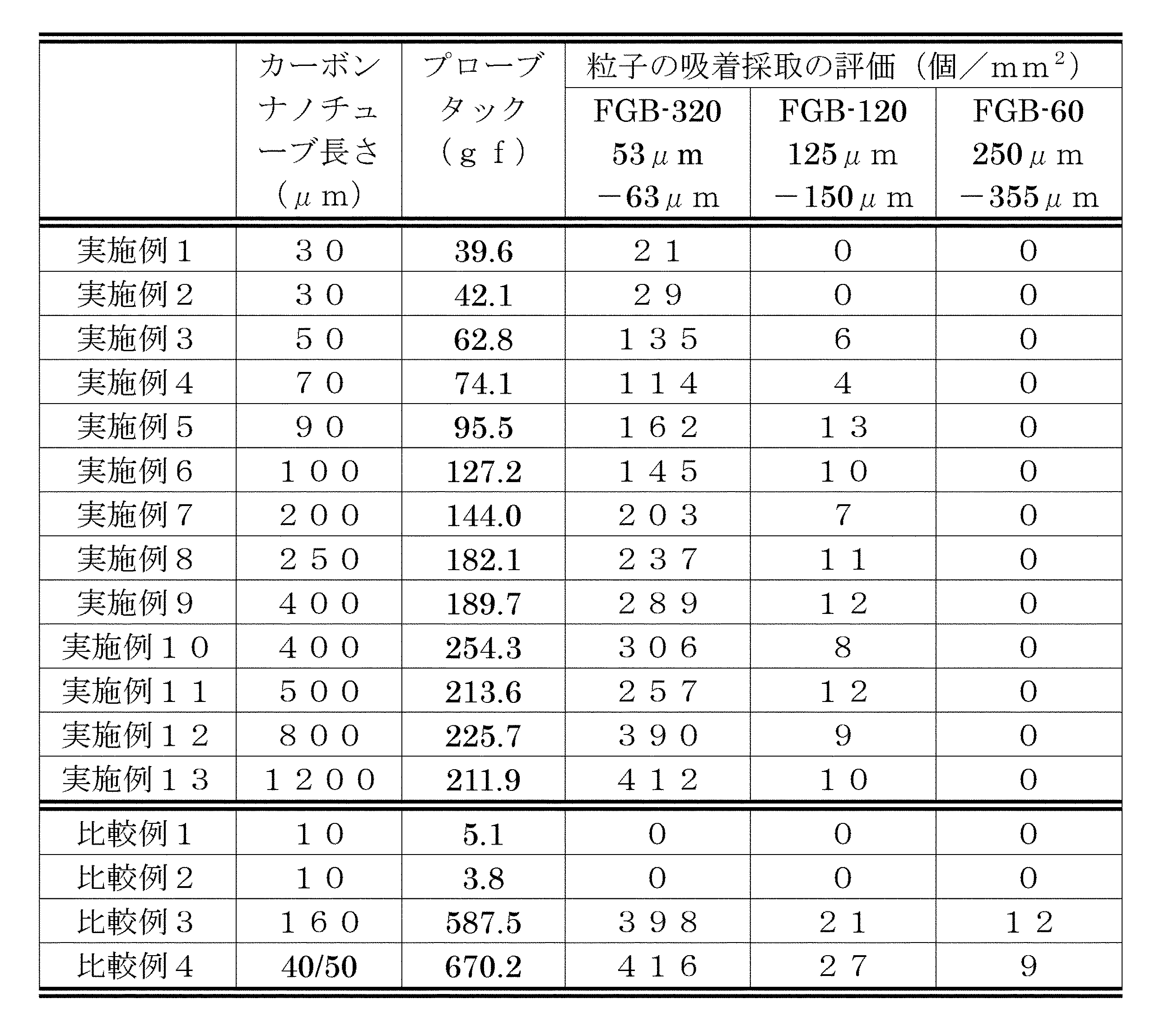
- Various evaluations were performed using the obtained carbon nanotube aggregate (1) as a viscoelastic body (1), and the results are summarized in Tables 1 and 2.
- Example 2 Except that the thickness of the Fe thin film was 1 nm, the same procedure as in Example 1 was performed to obtain a carbon nanotube aggregate (2) in which the carbon nanotubes were aligned in the length direction.
- the carbon nanotubes included in the carbon nanotube aggregate (2) had a length of 30 ⁇ m.
- the mode value was present in two layers, and the relative frequency was 75%.
- Various evaluations were performed using the obtained carbon nanotube aggregate (2) as a viscoelastic body (2), and the results are summarized in Tables 1 and 2.
- Example 3 The carbon nanotubes are aligned in the length direction in the same manner as in Example 2 except that the standing time after filling the tube with a mixed gas of helium / hydrogen / ethylene (85/50/5 sccm, moisture content 600 ppm) is 3 minutes. As a result, an aggregate (3) of carbon nanotubes oriented in the direction was obtained. The length of the carbon nanotubes included in the carbon nanotube aggregate (3) was 50 ⁇ m. In the distribution of the number of carbon nanotubes provided in the carbon nanotube aggregate (3), the mode value was present in two layers, and the relative frequency was 75%. Various evaluations were performed using the obtained carbon nanotube aggregate (3) as a viscoelastic body (3), and the results are summarized in Tables 1 and 2.
- Example 4 Similar to Example 1, except that the thickness of the Fe thin film was set to 2 nm and the standing time after filling the tube with a mixed gas of helium / hydrogen / ethylene (85/50/5 sccm, moisture content 600 ppm) was 5 minutes.
- the carbon nanotube aggregate (4) in which the carbon nanotubes were aligned in the length direction was obtained.
- the carbon nanotubes included in the carbon nanotube aggregate (4) had a length of 70 ⁇ m.
- the mode value was present in 7-8 layers, and the relative frequency was 66%.
- Various evaluations were performed using the obtained carbon nanotube aggregate (4) as a viscoelastic body (4), and the results are summarized in Tables 1 and 2.
- Example 5 An Al thin film (thickness 10 nm) was formed on a silicon substrate (made by KST, wafer with thermal oxide film, thickness 1000 ⁇ m) using a vacuum deposition apparatus (made by JEOL, JEE-4X Vacuum Evaporator), and then oxidized at 450 ° C. for 1 hour. Treated. In this way, an Al 2 O 3 film was formed on the silicon substrate. On this Al 2 O 3 film, an Fe thin film (thickness 2 nm) was further deposited by a sputtering apparatus (manufactured by ULVAC, RFS-200) to form a catalyst layer.
- a sputtering apparatus manufactured by ULVAC, RFS-200
- the obtained silicon substrate with a catalyst layer was cut and placed in a 30 mm ⁇ quartz tube, and a helium / hydrogen (120/80 sccm) mixed gas maintained at a moisture content of 350 ppm was allowed to flow into the quartz tube for 30 minutes. Was replaced. Thereafter, the inside of the tube was gradually raised to 765 ° C. in 35 minutes using an electric tubular furnace, and stabilized at 765 ° C. While maintaining the temperature at 765 ° C., the tube was filled with a mixed gas of helium / hydrogen / ethylene (105/80/15 sccm, moisture content 350 ppm) and left for 5 minutes to grow carbon nanotubes on the substrate.
- Example 6 Example 1 except that acetylene was used instead of ethylene and the standing time after filling the tube with a mixed gas of helium / hydrogen / acetylene (85/50/5 sccm, moisture content 600 ppm) was 7 minutes.
- the carbon nanotube aggregate (6) in which the carbon nanotubes were aligned in the length direction was obtained.
- the length of the carbon nanotube with which the carbon nanotube aggregate (6) is provided was 100 ⁇ m.
- the mode value was present in 7-8 layers, and the relative frequency was 66%.
- Example 7 The carbon nanotubes are aligned in the length direction in the same manner as in Example 2 except that the standing time after filling the tube with a mixed gas of helium / hydrogen / ethylene (85/50/5 sccm, moisture content 600 ppm) is 10 minutes.
- a mixed gas of helium / hydrogen / ethylene 85/50/5 sccm, moisture content 600 ppm
- an aggregate (7) of carbon nanotubes oriented in the direction of was obtained.
- the length of the carbon nanotube with which the carbon nanotube aggregate (7) is provided was 200 ⁇ m.
- the mode value was present in two layers, and the relative frequency was 75%.
- Example 8 The carbon nanotubes were measured in the length direction in the same manner as in Example 5 except that the standing time after filling the tube with a mixed gas of helium / hydrogen / ethylene (105/80/15 sccm, moisture content 350 ppm) was 10 minutes. Thus, an aggregate (8) of carbon nanotubes oriented in the direction of was obtained. The length of the carbon nanotube with which the carbon nanotube aggregate (8) is provided was 250 ⁇ m. In the number distribution of the carbon nanotubes provided in the carbon nanotube aggregate (8), the distribution width of the number distribution is 17 layers (4 to 20 layers), and the mode exists in the 4th and 8th layers, The relative frequencies were 20% each. Various evaluations were performed using the obtained carbon nanotube aggregate (8) as a viscoelastic body (8), and the results are summarized in Tables 1 and 2.
- Example 9 The carbon nanotubes were measured in the length direction in the same manner as in Example 1 except that the standing time after filling the tube with a mixed gas of helium / hydrogen / ethylene (85/50/5 sccm, moisture content 600 ppm) was 20 minutes. As a result, an aggregate (9) of carbon nanotubes oriented in the direction was obtained. The length of the carbon nanotube with which the carbon nanotube aggregate (9) is provided was 400 ⁇ m. In the distribution of the number of carbon nanotubes provided in the carbon nanotube aggregate (9), the mode value was present in one layer, and the relative frequency was 61%.
- Various evaluations were performed using the obtained carbon nanotube aggregate (9) as a viscoelastic body (9), and the results are summarized in Tables 1 and 2.
- Example 10 The carbon nanotubes were measured in the length direction in the same manner as in Example 5 except that the standing time after filling the tube with a mixed gas of helium / hydrogen / ethylene (105/80/15 sccm, moisture content 350 ppm) was 20 minutes. Thus, an aggregate (10) of carbon nanotubes oriented in the direction of was obtained. The length of the carbon nanotube with which the carbon nanotube aggregate (10) is provided was 400 ⁇ m. In the number distribution of carbon nanotubes provided in the carbon nanotube aggregate (10), the distribution width of the number distribution is 17 layers (4 to 20 layers), and the mode exists in 4 layers and 8 layers, The relative frequencies were 20% each. Various evaluations were performed using the obtained carbon nanotube aggregate (10) as a viscoelastic body (10), and the results are summarized in Tables 1 and 2.
- Example 11 The carbon nanotubes are aligned in the length direction in the same manner as in Example 2 except that the standing time after filling the tube with a mixed gas of helium / hydrogen / ethylene (85/50/5 sccm, moisture content 600 ppm) is 20 minutes.
- a mixed gas of helium / hydrogen / ethylene 85/50/5 sccm, moisture content 600 ppm
- the length of the carbon nanotube with which the carbon nanotube aggregate (11) is provided was 500 ⁇ m.
- the mode value was present in two layers, and the relative frequency was 75%.
- Example 12 The carbon nanotubes are aligned in the length direction in the same manner as in Example 4 except that the standing time after filling the tube with a mixed gas of helium / hydrogen / ethylene (85/50/5 sccm, moisture content 600 ppm) is 40 minutes.
- an aggregate (12) of carbon nanotubes oriented in the direction of was obtained.
- the carbon nanotubes included in the carbon nanotube aggregate (12) had a length of 800 ⁇ m.
- the mode value was present in three layers, and the relative frequency was 72%.
- Various evaluations were performed using the obtained carbon nanotube aggregate (12) as a viscoelastic body (12), and the results are summarized in Tables 1 and 2.
- Example 13 The carbon nanotubes are aligned in the length direction in the same manner as in Example 2 except that the standing time after filling the tube with a mixed gas of helium / hydrogen / ethylene (85/50/5 sccm, moisture content 600 ppm) is 60 minutes. As a result, an aggregate (13) of carbon nanotubes oriented in the direction was obtained. The length of the carbon nanotubes provided in the carbon nanotube aggregate (13) was 1200 ⁇ m. In the distribution of the number of carbon nanotubes provided in the carbon nanotube aggregate (13), the mode value was present in two layers, and the relative frequency was 75%. Various evaluations were performed using the obtained carbon nanotube aggregate (13) as a viscoelastic body (13), and the results are summarized in Tables 1 and 2.
- the aggregate of carbon nanotubes of the present invention is suitably used for a viscoelastic body that has a small tack and excellent handleability and can selectively acquire particles having a specific particle size from a group of particles having a wide particle size distribution. be able to.
- Carbon nanotube aggregate 1 Base material 2 Carbon nanotube 2a One end of carbon nanotube
Landscapes
- Chemical & Material Sciences (AREA)
- Engineering & Computer Science (AREA)
- Nanotechnology (AREA)
- Materials Engineering (AREA)
- Organic Chemistry (AREA)
- Physics & Mathematics (AREA)
- Condensed Matter Physics & Semiconductors (AREA)
- General Physics & Mathematics (AREA)
- Crystallography & Structural Chemistry (AREA)
- Inorganic Chemistry (AREA)
- Composite Materials (AREA)
- Manufacturing & Machinery (AREA)
- Chemical Kinetics & Catalysis (AREA)
- Carbon And Carbon Compounds (AREA)
- Catalysts (AREA)
Abstract
Description
複数のカーボンナノチューブを備え、
該カーボンナノチューブが複数層を有し、
該カーボンナノチューブの層数分布の分布幅が10層以上であり、該層数分布の最頻値の相対頻度が25%以下であり、
該カーボンナノチューブの長さが10μmより大きい。
複数のカーボンナノチューブを備え、
該カーボンナノチューブが複数層を有し、
該カーボンナノチューブの層数分布の最頻値が層数10層以下に存在し、該最頻値の相対頻度が30%以上であり、
該カーボンナノチューブの長さが10μmより大きい。
図1は、本発明の好ましい実施形態におけるカーボンナノチューブ集合体の概略断面図(各構成部分を明示するために縮尺は正確に記載されていない)を示す。カーボンナノチューブ集合体10は、基材1と、カーボンナノチューブ2を備える。カーボンナノチューブ2の片端2aは、基材1に固定されている。カーボンナノチューブ2は、長さ方向Lに配向している。カーボンナノチューブ2は、好ましくは、基材1に対して略垂直方向に配向している。本図示例とは異なり、カーボンナノチューブが基材を備えない場合であっても、カーボンナノチューブは互いにファンデルワールス力によって集合体として存在し得るので、本発明のカーボンナノチューブ集合体は、基材を備えない集合体であっても良い。
本発明のカーボンナノチューブ集合体の好ましい実施形態の1つ(以下、第1の好ましい実施形態と称することがある)は、複数のカーボンナノチューブを備え、該カーボンナノチューブが複数層を有し、該カーボンナノチューブの層数分布の分布幅が10層以上であり、該層数分布の最頻値の相対頻度が25%以下であり、該カーボンナノチューブの長さが10μmより大きい。
本発明のカーボンナノチューブ集合体の好ましい実施形態の別の1つ(以下、第2の好ましい実施形態と称することがある)は、複数のカーボンナノチューブを備え、該カーボンナノチューブが複数層を有し、該カーボンナノチューブの層数分布の最頻値が層数10層以下に存在し、該最頻値の相対頻度が30%以上であり、該カーボンナノチューブの長さが10μmを超えて500μm未満である。
本発明のカーボンナノチューブ集合体の製造方法としては、任意の適切な方法を採用し得る。
本発明の粘弾性体は、本発明のカーボンナノチューブ集合体を含む。
本発明のカーボンナノチューブ集合体におけるカーボンナノチューブの層数および層数分布は、走査型電子顕微鏡(SEM)および/または透過電子顕微鏡(TEM)によって測定した。得られたカーボンナノチューブ集合体の中から少なくとも10本以上、好ましくは20本以上のカーボンナノチューブをSEMおよび/またはTEMにより観察し、各カーボンナノチューブの層数を調べ、層数分布を作成した。
粒子として、下記の4種のガラス系研磨剤(不二製作所製)をそれぞれ用いた。
FGB-30(粒子径:500μm-710μm)
FGB-60(粒子径:250μm-355μm)
FGB-120(粒子径:125μm-150μm)
FGB-320(粒子径:53μm-63μm)
上記粒子上に粘弾性体を置き、5kgローラーで一往復して圧着した。
粒子が粘着採取された粘弾性体の表面をSEMにて観察し、1mm×1mmの領域に付着している粒子の数を数えた。
粒子として、下記の3種のガラス系研磨剤(不二製作所製)をそれぞれ用いた。
FGB-60(粒子径:250μm-355μm)
FGB-120(粒子径:125μm-150μm)
FGB-320(粒子径:53μm-63μm)
粘弾性体の50mm上から上記粒子を降り掛け(衝突速度=1m/s)、粘弾性体表面に粒子を吸着させた。
粒子が吸着採取された粘弾性体の表面をSEMにて観察し、1mm×1mmの領域に付着している粒子の数を数えた。
下記の条件によってプローブタック試験を行い、粘着力の最大値を測定した。
装置:タッキング試験機(RESCA製)
プローブ:SUS5mmφ
Preload:500gf
Press Speed:1mm/min
Press Time:5s
Test Speed:2.5mm/min
基板としてのシリコンウェハ(シリコンテクノロジー製)上に、スパッタ装置(ULVAC製、RFS-200)により、Al薄膜(厚み10nm)を形成した。このAl薄膜上に、さらにスパッタ装置(ULVAC製、RFS-200)にてFe薄膜(厚み0.35nm)を蒸着した。
その後、この基板を30mmφの石英管内に載置し、水分600ppmに保ったヘリウム/水素(90/50sccm)混合ガスを石英管内に30分間流して、管内を置換した。その後、電気管状炉を用いて管内を765℃まで昇温させ、765℃にて安定させた。765℃にて温度を保持したまま、ヘリウム/水素/エチレン(85/50/5sccm、水分率600ppm)混合ガスを管内に充填させ、1分間放置してカーボンナノチューブを基板上に成長させ、カーボンナノチューブが長さ方向に配向しているカーボンナノチューブ集合体(1)を得た。
カーボンナノチューブ集合体(1)が備えるカーボンナノチューブの長さは30μmであった。
カーボンナノチューブ集合体(1)が備えるカーボンナノチューブの層数分布において、最頻値は1層に存在し、相対頻度は61%であった。
得られたカーボンナノチューブ集合体(1)を粘弾性体(1)として、各種評価を行い、結果を表1、表2にまとめた。
Fe薄膜の厚みを1nmとした以外は、実施例1と同様に行い、カーボンナノチューブが長さ方向に配向しているカーボンナノチューブ集合体(2)を得た。
カーボンナノチューブ集合体(2)が備えるカーボンナノチューブの長さは30μmであった。
カーボンナノチューブ集合体(2)が備えるカーボンナノチューブの層数分布において、最頻値は2層に存在し、相対頻度は75%であった。
得られたカーボンナノチューブ集合体(2)を粘弾性体(2)として、各種評価を行い、結果を表1、表2にまとめた。
ヘリウム/水素/エチレン(85/50/5sccm、水分率600ppm)混合ガスを管内に充填させた後の放置時間を3分間とした以外は、実施例2と同様に行い、カーボンナノチューブが長さ方向に配向しているカーボンナノチューブ集合体(3)を得た。
カーボンナノチューブ集合体(3)が備えるカーボンナノチューブの長さは50μmであった。
カーボンナノチューブ集合体(3)が備えるカーボンナノチューブの層数分布において、最頻値は2層に存在し、相対頻度は75%であった。
得られたカーボンナノチューブ集合体(3)を粘弾性体(3)として、各種評価を行い、結果を表1、表2にまとめた。
Fe薄膜の厚みを2nmとし、ヘリウム/水素/エチレン(85/50/5sccm、水分率600ppm)混合ガスを管内に充填させた後の放置時間を5分間とした以外は、実施例1と同様に行い、カーボンナノチューブが長さ方向に配向しているカーボンナノチューブ集合体(4)を得た。
カーボンナノチューブ集合体(4)が備えるカーボンナノチューブの長さは70μmであった。
カーボンナノチューブ集合体(4)が備えるカーボンナノチューブの層数分布において、最頻値は7-8層に存在し、相対頻度は66%であった。
得られたカーボンナノチューブ集合体(4)を粘弾性体(4)として、各種評価を行い、結果を表1、表2にまとめた。
シリコン基板(KST製、熱酸化膜付ウェハ、厚み1000μm)上に、真空蒸着装置(JEOL製、JEE-4X Vacuum Evaporator)により、Al薄膜(厚み10nm)を形成した後、450℃で1時間酸化処理を施した。このようにして、シリコン基板上にAl2O3膜を形成した。このAl2O3膜上に、さらにスパッタ装置(ULVAC製、RFS-200)にてFe薄膜(厚み2nm)を蒸着させて触媒層を形成した。
次に、得られた触媒層付シリコン基板をカットして、30mmφの石英管内に載置し、水分350ppmに保ったヘリウム/水素(120/80sccm)混合ガスを石英管内に30分間流して、管内を置換した。その後、電気管状炉を用いて管内を765℃まで35分間で段階的に昇温させ、765℃にて安定させた。765℃にて温度を保持したまま、ヘリウム/水素/エチレン(105/80/15sccm、水分率350ppm)混合ガスを管内に充填させ、5分間放置してカーボンナノチューブを基板上に成長させ、カーボンナノチューブが長さ方向に配向しているカーボンナノチューブ集合体(5)を得た。
カーボンナノチューブ集合体(5)が備えるカーボンナノチューブの長さは90μmであった。
カーボンナノチューブ集合体(5)が備えるカーボンナノチューブの層数分布において、層数分布の分布幅は17層(4層~20層)であり、最頻値は4層と8層に存在し、相対頻度はそれぞれ20%であった。
得られたカーボンナノチューブ集合体(5)を粘弾性体(5)として、各種評価を行い、結果を表1、表2にまとめた。
エチレンの代わりにアセチレンを用い、ヘリウム/水素/アセチレン(85/50/5sccm、水分率600ppm)混合ガスを管内に充填させた後の放置時間を7分間とした以外は、実施例1と同様に行い、カーボンナノチューブが長さ方向に配向しているカーボンナノチューブ集合体(6)を得た。
カーボンナノチューブ集合体(6)が備えるカーボンナノチューブの長さは100μmであった。
カーボンナノチューブ集合体(6)が備えるカーボンナノチューブの層数分布において、最頻値は7-8層に存在し、相対頻度は66%であった。
得られたカーボンナノチューブ集合体(6)を粘弾性体(6)として、各種評価を行い、結果を表1、表2にまとめた。
ヘリウム/水素/エチレン(85/50/5sccm、水分率600ppm)混合ガスを管内に充填させた後の放置時間を10分間とした以外は、実施例2と同様に行い、カーボンナノチューブが長さ方向に配向しているカーボンナノチューブ集合体(7)を得た。
カーボンナノチューブ集合体(7)が備えるカーボンナノチューブの長さは200μmであった。
カーボンナノチューブ集合体(7)が備えるカーボンナノチューブの層数分布において、最頻値は2層に存在し、相対頻度は75%であった。
得られたカーボンナノチューブ集合体(7)を粘弾性体(7)として、各種評価を行い、結果を表1、表2にまとめた。
ヘリウム/水素/エチレン(105/80/15sccm、水分率350ppm)混合ガスを管内に充填させた後の放置時間を10分間とした以外は、実施例5と同様に行い、カーボンナノチューブが長さ方向に配向しているカーボンナノチューブ集合体(8)を得た。
カーボンナノチューブ集合体(8)が備えるカーボンナノチューブの長さは250μmであった。
カーボンナノチューブ集合体(8)が備えるカーボンナノチューブの層数分布において、層数分布の分布幅は17層(4層~20層)層であり、最頻値は4層と8層に存在し、相対頻度はそれぞれ20%であった。
得られたカーボンナノチューブ集合体(8)を粘弾性体(8)として、各種評価を行い、結果を表1、表2にまとめた。
ヘリウム/水素/エチレン(85/50/5sccm、水分率600ppm)混合ガスを管内に充填させた後の放置時間を20分間とした以外は、実施例1と同様に行い、カーボンナノチューブが長さ方向に配向しているカーボンナノチューブ集合体(9)を得た。
カーボンナノチューブ集合体(9)が備えるカーボンナノチューブの長さは400μmであった。
カーボンナノチューブ集合体(9)が備えるカーボンナノチューブの層数分布において、最頻値は1層に存在し、相対頻度は61%であった。
得られたカーボンナノチューブ集合体(9)を粘弾性体(9)として、各種評価を行い、結果を表1、表2にまとめた。
ヘリウム/水素/エチレン(105/80/15sccm、水分率350ppm)混合ガスを管内に充填させた後の放置時間を20分間とした以外は、実施例5と同様に行い、カーボンナノチューブが長さ方向に配向しているカーボンナノチューブ集合体(10)を得た。
カーボンナノチューブ集合体(10)が備えるカーボンナノチューブの長さは400μmであった。
カーボンナノチューブ集合体(10)が備えるカーボンナノチューブの層数分布において、層数分布の分布幅は17層(4層~20層)層であり、最頻値は4層と8層に存在し、相対頻度はそれぞれ20%であった。
得られたカーボンナノチューブ集合体(10)を粘弾性体(10)として、各種評価を行い、結果を表1、表2にまとめた。
ヘリウム/水素/エチレン(85/50/5sccm、水分率600ppm)混合ガスを管内に充填させた後の放置時間を20分間とした以外は、実施例2と同様に行い、カーボンナノチューブが長さ方向に配向しているカーボンナノチューブ集合体(11)を得た。
カーボンナノチューブ集合体(11)が備えるカーボンナノチューブの長さは500μmであった。
カーボンナノチューブ集合体(11)が備えるカーボンナノチューブの層数分布において、最頻値は2層に存在し、相対頻度は75%であった。
得られたカーボンナノチューブ集合体(11)を粘弾性体(11)として、各種評価を行い、結果を表1、表2にまとめた。
ヘリウム/水素/エチレン(85/50/5sccm、水分率600ppm)混合ガスを管内に充填させた後の放置時間を40分間とした以外は、実施例4と同様に行い、カーボンナノチューブが長さ方向に配向しているカーボンナノチューブ集合体(12)を得た。
カーボンナノチューブ集合体(12)が備えるカーボンナノチューブの長さは800μmであった。
カーボンナノチューブ集合体(12)が備えるカーボンナノチューブの層数分布において、最頻値は3層に存在し、相対頻度は72%であった。
得られたカーボンナノチューブ集合体(12)を粘弾性体(12)として、各種評価を行い、結果を表1、表2にまとめた。
ヘリウム/水素/エチレン(85/50/5sccm、水分率600ppm)混合ガスを管内に充填させた後の放置時間を60分間とした以外は、実施例2と同様に行い、カーボンナノチューブが長さ方向に配向しているカーボンナノチューブ集合体(13)を得た。
カーボンナノチューブ集合体(13)が備えるカーボンナノチューブの長さは1200μmであった。
カーボンナノチューブ集合体(13)が備えるカーボンナノチューブの層数分布において、最頻値は2層に存在し、相対頻度は75%であった。
得られたカーボンナノチューブ集合体(13)を粘弾性体(13)として、各種評価を行い、結果を表1、表2にまとめた。
ヘリウム/水素/エチレン(85/50/5sccm、水分率600ppm)混合ガスを管内に充填させた後の放置時間を30秒間とした以外は、実施例1と同様に行い、カーボンナノチューブが長さ方向に配向しているカーボンナノチューブ集合体(C1)を得た。
カーボンナノチューブ集合体(C1)が備えるカーボンナノチューブの長さは10μmであった。
カーボンナノチューブ集合体(C1)が備えるカーボンナノチューブの層数分布において、最頻値は1層に存在し、相対頻度は61%であった。
得られたカーボンナノチューブ集合体(C1)を粘弾性体(C1)として、各種評価を行い、結果を表1、表2にまとめた。
ヘリウム/水素/エチレン(85/50/5sccm、水分率600ppm)混合ガスを管内に充填させた後の放置時間を30秒間とした以外は、実施例2と同様に行い、カーボンナノチューブが長さ方向に配向しているカーボンナノチューブ集合体(C2)を得た。
カーボンナノチューブ集合体(C2)が備えるカーボンナノチューブの長さは10μmであった。
カーボンナノチューブ集合体(C2)が備えるカーボンナノチューブの層数分布において、最頻値は2層に存在し、相対頻度は75%であった。
得られたカーボンナノチューブ集合体(C2)を粘弾性体(C2)として、各種評価を行い、結果を表1、表2にまとめた。
両面粘着テープ(日東電工株式会社製、No.5000N)を粘弾性体(C3)として、各種評価を行い、結果を表1、表2にまとめた。
3Mポリイミド両面テープ(住友3M製、4390)を粘弾性体(C4)として、各種評価を行い、結果を表1、表2にまとめた。

1 基材
2 カーボンナノチューブ
2a カーボンナノチューブの片端
Claims (11)
- 複数のカーボンナノチューブを備え、
該カーボンナノチューブが複数層を有し、
該カーボンナノチューブの層数分布の分布幅が10層以上であり、該層数分布の最頻値の相対頻度が25%以下であり、
該カーボンナノチューブの長さが10μmより大きい、
カーボンナノチューブ集合体。 - 前記層数分布の最頻値が、層数2層から層数10層の範囲に存在する、請求項1に記載のカーボンナノチューブ集合体。
- 前記カーボンナノチューブの長さが300μm未満である、請求項1または2に記載のカーボンナノチューブ集合体。
- 複数のカーボンナノチューブを備え、
該カーボンナノチューブが複数層を有し、
該カーボンナノチューブの層数分布の最頻値が層数10層以下に存在し、該最頻値の相対頻度が30%以上であり、
該カーボンナノチューブの長さが10μmより大きい、
カーボンナノチューブ集合体。 - 前記層数分布の最頻値が層数6層以下に存在する、請求項4に記載のカーボンナノチューブ集合体。
- 前記カーボンナノチューブの長さが500μm未満である、請求項4または5に記載のカーボンナノチューブ集合体。
- 請求項1から6までのいずれかに記載のカーボンナノチューブ集合体を含む、粘弾性体。
- プローブタック試験におけるプローブタックが、25℃において200gf以下である、請求項7に記載の粘弾性体。
- 粒径500μm未満の粒子を選択的に粘着採取する、請求項7または8に記載の粘弾性体。
- 粒径200μm以下の粒子を選択的に吸着採取する、請求項7または8に記載の粘弾性体。
- 基材をさらに備え、前記カーボンナノチューブの片端が該基材に固定されている、請求項7から10までのいずれかに記載の粘弾性体。
Priority Applications (3)
| Application Number | Priority Date | Filing Date | Title |
|---|---|---|---|
| CN201280060366.7A CN103974902B (zh) | 2011-12-08 | 2012-10-05 | 碳纳米管集合体和使用该碳纳米管集合体的粘弹性体 |
| KR1020147014890A KR101997946B1 (ko) | 2011-12-08 | 2012-10-05 | 카본 나노 튜브 집합체 및 그것을 사용한 점탄성체 |
| US14/359,421 US9795994B2 (en) | 2011-12-08 | 2012-10-05 | Carbon nanotube assembly and viscoelastic body using same |
Applications Claiming Priority (2)
| Application Number | Priority Date | Filing Date | Title |
|---|---|---|---|
| JP2011-268979 | 2011-12-08 | ||
| JP2011268979A JP5893374B2 (ja) | 2011-12-08 | 2011-12-08 | カーボンナノチューブ集合体およびそれを用いた粘弾性体 |
Publications (1)
| Publication Number | Publication Date |
|---|---|
| WO2013084580A1 true WO2013084580A1 (ja) | 2013-06-13 |
Family
ID=48573963
Family Applications (1)
| Application Number | Title | Priority Date | Filing Date |
|---|---|---|---|
| PCT/JP2012/075980 Ceased WO2013084580A1 (ja) | 2011-12-08 | 2012-10-05 | カーボンナノチューブ集合体およびそれを用いた粘弾性体 |
Country Status (5)
| Country | Link |
|---|---|
| US (1) | US9795994B2 (ja) |
| JP (1) | JP5893374B2 (ja) |
| KR (1) | KR101997946B1 (ja) |
| CN (1) | CN103974902B (ja) |
| WO (1) | WO2013084580A1 (ja) |
Families Citing this family (5)
| Publication number | Priority date | Publication date | Assignee | Title |
|---|---|---|---|---|
| JP6616194B2 (ja) * | 2016-01-15 | 2019-12-04 | 日東電工株式会社 | 載置部材 |
| JP6975545B2 (ja) * | 2016-10-03 | 2021-12-01 | 日東電工株式会社 | カーボンナノチューブ集合体 |
| EP3579249B1 (en) * | 2017-02-03 | 2024-04-10 | Furukawa Electric Co., Ltd. | Carbon nanotube wire, method for manufacturing carbon nanotube, and method for manufacturing carbon nanotube wire |
| CN118289745A (zh) | 2020-02-28 | 2024-07-05 | 日本瑞翁株式会社 | 碳纳米管集合体 |
| USD1090696S1 (en) | 2024-06-24 | 2025-08-26 | E. Mishan & Sons, Inc. | Tape dispenser |
Citations (5)
| Publication number | Priority date | Publication date | Assignee | Title |
|---|---|---|---|---|
| WO2009128342A1 (ja) * | 2008-04-16 | 2009-10-22 | 日東電工株式会社 | 繊維状柱状構造体集合体およびそれを用いた粘着部材 |
| WO2009128343A1 (ja) * | 2008-04-16 | 2009-10-22 | 日東電工株式会社 | 繊維状柱状構造体集合体およびそれを用いた粘着部材 |
| WO2010032525A1 (ja) * | 2008-09-18 | 2010-03-25 | 日東電工株式会社 | カーボンナノチューブ集合体 |
| WO2011077784A1 (ja) * | 2009-12-25 | 2011-06-30 | 日東電工株式会社 | カーボンナノチューブ複合構造体および粘着部材 |
| WO2011077785A1 (ja) * | 2009-12-25 | 2011-06-30 | 日東電工株式会社 | カーボンナノチューブ複合構造体および粘着部材 |
Family Cites Families (6)
| Publication number | Priority date | Publication date | Assignee | Title |
|---|---|---|---|---|
| US7132161B2 (en) | 1999-06-14 | 2006-11-07 | Energy Science Laboratories, Inc. | Fiber adhesive material |
| KR100376197B1 (ko) | 1999-06-15 | 2003-03-15 | 일진나노텍 주식회사 | 탄소 소오스 가스 분해용 촉매금속막을 이용한탄소나노튜브의 저온 합성 방법 |
| US20060068195A1 (en) | 2004-05-19 | 2006-03-30 | Arun Majumdar | Electrically and thermally conductive carbon nanotube or nanofiber array dry adhesive |
| US7459013B2 (en) | 2004-11-19 | 2008-12-02 | International Business Machines Corporation | Chemical and particulate filters containing chemically modified carbon nanotube structures |
| JP2008538531A (ja) * | 2005-04-22 | 2008-10-30 | セルドン テクノロジーズ,エルエルシー | カーボンナノチューブを含む物品および流体の浄化にこれを使用するための方法 |
| JP5087414B2 (ja) | 2008-01-22 | 2012-12-05 | 日東電工株式会社 | 光硬化型アクリル系粘弾性体組成物、アクリル系粘弾性体、アクリル系粘弾性体層テープ又はシート、及びそれらの製造方法 |
-
2011
- 2011-12-08 JP JP2011268979A patent/JP5893374B2/ja not_active Expired - Fee Related
-
2012
- 2012-10-05 US US14/359,421 patent/US9795994B2/en not_active Expired - Fee Related
- 2012-10-05 WO PCT/JP2012/075980 patent/WO2013084580A1/ja not_active Ceased
- 2012-10-05 CN CN201280060366.7A patent/CN103974902B/zh not_active Expired - Fee Related
- 2012-10-05 KR KR1020147014890A patent/KR101997946B1/ko not_active Expired - Fee Related
Patent Citations (5)
| Publication number | Priority date | Publication date | Assignee | Title |
|---|---|---|---|---|
| WO2009128342A1 (ja) * | 2008-04-16 | 2009-10-22 | 日東電工株式会社 | 繊維状柱状構造体集合体およびそれを用いた粘着部材 |
| WO2009128343A1 (ja) * | 2008-04-16 | 2009-10-22 | 日東電工株式会社 | 繊維状柱状構造体集合体およびそれを用いた粘着部材 |
| WO2010032525A1 (ja) * | 2008-09-18 | 2010-03-25 | 日東電工株式会社 | カーボンナノチューブ集合体 |
| WO2011077784A1 (ja) * | 2009-12-25 | 2011-06-30 | 日東電工株式会社 | カーボンナノチューブ複合構造体および粘着部材 |
| WO2011077785A1 (ja) * | 2009-12-25 | 2011-06-30 | 日東電工株式会社 | カーボンナノチューブ複合構造体および粘着部材 |
Also Published As
| Publication number | Publication date |
|---|---|
| KR101997946B1 (ko) | 2019-07-08 |
| US9795994B2 (en) | 2017-10-24 |
| JP5893374B2 (ja) | 2016-03-23 |
| CN103974902B (zh) | 2016-05-18 |
| JP2013119504A (ja) | 2013-06-17 |
| US20140322517A1 (en) | 2014-10-30 |
| KR20140112476A (ko) | 2014-09-23 |
| CN103974902A (zh) | 2014-08-06 |
Similar Documents
| Publication | Publication Date | Title |
|---|---|---|
| JP4545827B1 (ja) | 繊維状柱状構造体集合体およびそれを用いた粘着部材 | |
| JP4472785B2 (ja) | 繊維状柱状構造体集合体およびそれを用いた粘着部材 | |
| JP2014098107A (ja) | 宇宙空間で用いる把持材料 | |
| JP2017094412A (ja) | 部品把持具 | |
| JP5893374B2 (ja) | カーボンナノチューブ集合体およびそれを用いた粘弾性体 | |
| JP5199753B2 (ja) | カーボンナノチューブ集合体の製造方法 | |
| WO2012026203A1 (ja) | 繊維状柱状構造体集合体および粘着部材 | |
| WO2010125708A1 (ja) | カーボンナノチューブ集合体 | |
| WO2013115146A1 (ja) | ナノインデンター用試料固定部材 | |
| WO2013115144A1 (ja) | 原子間力顕微鏡用試料固定部材 | |
| WO2013084581A1 (ja) | 粘弾性体 | |
| JP5892778B2 (ja) | 広温度領域用粘弾性体 | |
| JP5892777B2 (ja) | 低アウトガス粘弾性体 | |
| JP2014215272A (ja) | 微粒子分離部材 | |
| WO2016031618A1 (ja) | クリーニング部材 |
Legal Events
| Date | Code | Title | Description |
|---|---|---|---|
| 121 | Ep: the epo has been informed by wipo that ep was designated in this application |
Ref document number: 12855988 Country of ref document: EP Kind code of ref document: A1 |
|
| WWE | Wipo information: entry into national phase |
Ref document number: 14359421 Country of ref document: US |
|
| ENP | Entry into the national phase |
Ref document number: 20147014890 Country of ref document: KR Kind code of ref document: A |
|
| NENP | Non-entry into the national phase |
Ref country code: DE |
|
| 122 | Ep: pct application non-entry in european phase |
Ref document number: 12855988 Country of ref document: EP Kind code of ref document: A1 |