WO2013084488A1 - Chargeur monté dans un véhicule - Google Patents
Chargeur monté dans un véhicule Download PDFInfo
- Publication number
- WO2013084488A1 WO2013084488A1 PCT/JP2012/007803 JP2012007803W WO2013084488A1 WO 2013084488 A1 WO2013084488 A1 WO 2013084488A1 JP 2012007803 W JP2012007803 W JP 2012007803W WO 2013084488 A1 WO2013084488 A1 WO 2013084488A1
- Authority
- WO
- WIPO (PCT)
- Prior art keywords
- vehicle
- primary coil
- coil
- unit
- secondary coil
- Prior art date
Links
Images


Classifications
-
- H—ELECTRICITY
- H02—GENERATION; CONVERSION OR DISTRIBUTION OF ELECTRIC POWER
- H02J—CIRCUIT ARRANGEMENTS OR SYSTEMS FOR SUPPLYING OR DISTRIBUTING ELECTRIC POWER; SYSTEMS FOR STORING ELECTRIC ENERGY
- H02J50/00—Circuit arrangements or systems for wireless supply or distribution of electric power
- H02J50/10—Circuit arrangements or systems for wireless supply or distribution of electric power using inductive coupling
-
- H—ELECTRICITY
- H02—GENERATION; CONVERSION OR DISTRIBUTION OF ELECTRIC POWER
- H02J—CIRCUIT ARRANGEMENTS OR SYSTEMS FOR SUPPLYING OR DISTRIBUTING ELECTRIC POWER; SYSTEMS FOR STORING ELECTRIC ENERGY
- H02J50/00—Circuit arrangements or systems for wireless supply or distribution of electric power
- H02J50/90—Circuit arrangements or systems for wireless supply or distribution of electric power involving detection or optimisation of position, e.g. alignment
-
- H—ELECTRICITY
- H02—GENERATION; CONVERSION OR DISTRIBUTION OF ELECTRIC POWER
- H02J—CIRCUIT ARRANGEMENTS OR SYSTEMS FOR SUPPLYING OR DISTRIBUTING ELECTRIC POWER; SYSTEMS FOR STORING ELECTRIC ENERGY
- H02J7/00—Circuit arrangements for charging or depolarising batteries or for supplying loads from batteries
- H02J7/0042—Circuit arrangements for charging or depolarising batteries or for supplying loads from batteries characterised by the mechanical construction
- H02J7/0044—Circuit arrangements for charging or depolarising batteries or for supplying loads from batteries characterised by the mechanical construction specially adapted for holding portable devices containing batteries
-
- H—ELECTRICITY
- H02—GENERATION; CONVERSION OR DISTRIBUTION OF ELECTRIC POWER
- H02J—CIRCUIT ARRANGEMENTS OR SYSTEMS FOR SUPPLYING OR DISTRIBUTING ELECTRIC POWER; SYSTEMS FOR STORING ELECTRIC ENERGY
- H02J2207/00—Indexing scheme relating to details of circuit arrangements for charging or depolarising batteries or for supplying loads from batteries
- H02J2207/10—Control circuit supply, e.g. means for supplying power to the control circuit
-
- H—ELECTRICITY
- H02—GENERATION; CONVERSION OR DISTRIBUTION OF ELECTRIC POWER
- H02J—CIRCUIT ARRANGEMENTS OR SYSTEMS FOR SUPPLYING OR DISTRIBUTING ELECTRIC POWER; SYSTEMS FOR STORING ELECTRIC ENERGY
- H02J7/00—Circuit arrangements for charging or depolarising batteries or for supplying loads from batteries
Definitions
- the present invention relates to an in-vehicle charger that performs contactless charging.
- the contactless charger cannot align the primary coil and the secondary coil. That is, the contactless charger cannot align the primary coil and the secondary coil unless the vehicle is in a state in which keyless entry control is not performed, for example, in a vehicle driving state. Therefore, the contactless charger cannot prepare for the start of charging unless the vehicle does not perform the keyless entry control, for example, the vehicle driving state. Thus, the restriction of the operation of the contactless charger according to the state of the vehicle is not desirable in terms of usability.
- An object of the present invention is to provide a vehicle-mounted charger with improved usability.
- An in-vehicle charger is an in-vehicle charger that performs contactless charging, and includes a control unit that controls energization of a primary coil, and positions of the primary coil and a secondary coil of a device to be charged.
- a position detection unit that detects a relationship; and a notification unit that performs notification to a user, and the control unit is configured such that the primary coil and the secondary coil detected by the position detection unit are not energized to the primary coil.
- the positional relationship is acquired, and control is performed so that the notification unit notifies the positional relationship.
- a vehicle-mounted charger includes a control unit that controls energization of a primary coil, a position detection unit that detects a positional relationship between the primary coil and a secondary coil of a device to be charged, and a notification to a user.
- a control unit that acquires a positional relationship between the primary coil and the secondary coil detected by the position detection unit in a state in which the primary coil is not energized, and the notification unit displays the positional relationship. Since the control is performed so that the notification is made, the on-vehicle charger is extremely easy to use.
- the in-vehicle charger according to the present invention can align the primary coil and the secondary coil even if the keyless entry control is performed immediately after the user gets into the vehicle. Therefore, immediately after the user gets into the vehicle, it is possible to prepare for the start of charging of the device to be charged placed at a chargeable position. After that, if there is no influence on vehicle control and charging is possible, the in-vehicle charger can start charging immediately. In this way, the on-vehicle charger is extremely easy to use.
- the perspective view of the vehicle-mounted charger of one embodiment The perspective view of the vehicle-mounted charger of one embodiment
- Side view of in-vehicle charger of one embodiment Top view of the position detector included in the in-vehicle charger of one embodiment
- the figure which shows the pulse signal and echo signal which are input into the position detection part with which the vehicle-mounted charger of one embodiment is equipped
- the block diagram which shows the internal structure of the vehicle-mounted charger of one embodiment, and the relationship with the mobile telephone to be charged The flowchart which shows operation of the in-vehicle charger of one embodiment
- the flowchart which shows operation of the in-vehicle charger of one embodiment The figure explaining the flag used with the vehicle-mounted charger of one embodiment
- FIG. 1 is a view showing a state in which a vehicle-mounted charger according to an embodiment of the present invention is mounted on a vehicle.
- a steering wheel 3 is disposed in front of the vehicle 1 in the vehicle 2, and an in-vehicle electronic device 4 is disposed on the left side of the handle 3.
- an in-vehicle charger 5 that is capable of contactless charging with respect to an electronic device such as a mobile phone is disposed below the in-vehicle electronic device 4 and between the driver seat and the passenger seat.
- FIG. 2 is a perspective view of the in-vehicle charger 5.
- 2 shows a state in which a mobile phone (an example of a device to be charged) 6 is placed on the installation surface 7 of the in-vehicle charger 5.
- the in-vehicle charger 5 includes an LED 8 serving as a notification unit 19 (see FIG. 7) for notifying the user that the mobile phone 6 is in a chargeable state, and a speaker 11 (see FIG. 7) installed inside the in-vehicle charger 5.
- 3 and FIG. 7) is provided with an opening 9 for transmitting sound from the outside.
- FIG. 3 is a perspective view of the in-vehicle charger 5 in which a part of the internal configuration is seen through.
- FIG. 4 is a side view of the in-vehicle charger 5 in which a part of the internal configuration is seen through.
- a primary coil 12 that transmits power to a secondary coil 10 for power reception built in the mobile phone 6, a speaker 11, Is provided.
- the primary coil 12 and the secondary coil 10 of the mobile phone 6 are made to face each other, so that the magnetic flux from the primary coil 12 reaches the secondary coil 10 of the mobile phone 6 to carry the mobile phone.
- a battery (not shown) held by the telephone 6 is charged.
- the installation surface 7 is preferably formed of synthetic resin so that magnetic flux from the primary coil 12 toward the secondary coil 10 of the mobile phone 6 can pass.
- a circuit for driving the primary coil 12, a mounting structure, and the like are omitted. Further, in the present embodiment, the primary coil 12 is fixed, and it is assumed that the primary coil 12 and the secondary coil 10 are aligned by the user moving the mobile phone 6 on the installation surface 7. To do.
- FIG. 5 is a top view of the position detector 13 provided in the in-vehicle charger 5.
- the position detection unit 13 includes, for example, a plurality of position detection coils 14 that detect positions in the X-axis direction and a plurality of position detection coils 15 that detect positions in the Y-axis direction.
- Each position detection coil has a loop shape elongated in the X-axis direction or the Y-axis direction.
- the plurality of position detection coils 14 are arranged at predetermined intervals along the X-axis direction.
- the plurality of position detection coils 15 are arranged at predetermined intervals along the Y-axis direction.
- the position detection coil to which the pulse signal 16 is input excites the secondary coil 10 of the mobile phone 6.
- the echo signal 17 generated by the energy of the current flowing in the excited secondary coil 10 acts on the position detection coil that has excited the secondary coil 10 described above.
- the position detection unit 13 can determine whether the secondary coil 10 is approaching any one of the plurality of position detection coils 14 and any one of the plurality of position detection coils 15.
- FIG. 7 is a block diagram showing the internal configuration of the in-vehicle charger 5 and the relationship with the mobile phone 6 to be charged.
- the in-vehicle charger 5 includes a control unit 18, a position detection unit 13, a notification unit 19, a communication unit 20, and a primary coil 12.
- the control unit 18 controls energization to the primary coil 12.
- the position detector 13 detects the positional relationship between the primary coil 12 and the secondary coil 10 of the mobile phone 6.
- the notification unit 19 notifies the user.
- reporting part 19 has LED8 shown in FIG. 2, and the speaker 11 shown in FIG.
- the communication part 20 communicates with the vehicle-mounted electronic device 4 provided in the vehicle 1 shown in FIG.
- control unit 18 acquires the positional relationship between the primary coil 12 and the secondary coil 10 detected by the position detection unit 13 and controls the notification unit 19 to notify the positional relationship.
- the communication unit 20 communicates with the in-vehicle electronic device 4 and acquires vehicle state information indicating whether or not the primary coil 12 can be energized. This is because energization of the primary coil 12 increases the reliability of vehicle control such as keyless entry control.
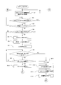
- FIGS. 8, 9, and 10 a procedure until the mobile phone 6 is placed on the installation surface 7 of the in-vehicle charger 5 and charging of the mobile phone 6 is started will be described.
- 8 and 9 are flowcharts showing the operation of the in-vehicle charger 5.
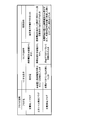
- FIG. 10 is a diagram for explaining a flag used in the in-vehicle charger 5.
- the control unit 18 controls the position detection unit 13 so as to detect the positional relationship between the primary coil 12 and the secondary coil 10 of the mobile phone 6 (step S1). At this time, each flag shown in FIG. 10 is set to “charging end flag: 0, secondary coil detection flag: 0, charging start flag: 0”. The energization of the primary coil 12 is in an off state, and the notification unit 19 does not notify anything.
- a first predetermined sound for example, a sound such as “Pololone
- step S ⁇ b> 8 the control unit 18 acquires the positional relationship between the primary coil 12 and the secondary coil 10 from the position detection unit 13, and the secondary coil 10 is close to the primary coil 12 or separated from the primary coil 12. Judgment is made.
- step S8: Yes the process proceeds to step S9, and when it is determined that the secondary coil 10 is separated from the primary coil 12 (step S8: No) goes to step S11.
- step S ⁇ b> 9 the control unit 18 inquires of the in-vehicle electronic device 4 whether the primary coil 12 can be energized via the communication unit 20, and determines that energization is possible based on the vehicle state information obtained by the communication unit 20. If so, the process proceeds to step S10. If it is determined that energization is not possible, the process returns to step S8. In step S ⁇ b> 10, the control unit 18 starts energizing the primary coil 12.
- step S ⁇ b> 11 the control unit 18 outputs a second predetermined sound (for example, a “beep” sound) from the speaker 11 in order to notify the user that the secondary coil 10 is separated from the primary coil 12. Sound. Furthermore, the control part 18 blinks LED8 with a short cycle (step S12). The user can be guided to move the mobile phone 6 to a rechargeable position on the installation surface 7 by the sound output in step S11 and the light blinking in step S12.
- a second predetermined sound for example, a “beep” sound
- control unit 18 confirms that the primary coil 12 is turned off (step S13), sets the charge start flag to 0 (step S14), and returns to step S1. Thereby, a user operation can be induced so that the user moves the mobile phone 6 to a chargeable position on the installation surface 7, that is, the secondary coil 10 and the primary coil 12 are sufficiently close to each other. .
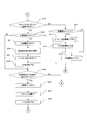
- the control unit 18 determines whether or not communication is possible between the secondary coil 10 and the primary coil 12 (step S15). If communication is possible (step S15: Yes), the process proceeds to step S21 and communication is not possible. If there is (step S15: No), the process proceeds to step S16. In addition, the procedure after step S16 is a process which requests
- step S19 the control part 18 sets a charge start flag to 0, and returns to step S1.
- step S ⁇ b> 17 the control unit 18 continuously plays the third predetermined sound (for example, a sound such as “Peepy”). Furthermore, the control part 18 blinks LED8 with a long cycle (step S18), and returns to step S1.
- a fourth predetermined sound for example, a sound such as “ping-pong”
- step S25 the control unit 18 determines whether a charging end notification has been received from the mobile phone 6, and if there is a charging end notification (step S25: Yes), proceeds to step S26, and if there is no charging end notification, returns to step S1. .
- step S26 the control unit 18 sets the charge end flag to 1.
- the controller 18 turns off the primary coil 12 (step S27), turns off the LED 8 (step S28), and returns to step S1.
- the in-vehicle charger 5 has a positional relationship between the control unit 18 that controls energization of the primary coil 12, the primary coil 12, and the secondary coil 10 of the mobile phone 6.
- the primary coil 12 and the secondary coil 10 can be aligned. Therefore, immediately after the user gets into the vehicle 1, it is possible to prepare for the start of charging of the mobile phone 6 placed at a chargeable position. Thereafter, if there is no influence on the vehicle control and charging is possible, the in-vehicle charger 5 can immediately start charging. In this way, the on-vehicle charger 5 is extremely easy to use.
- a vehicle-mounted charger includes a control unit that controls energization of a primary coil, a position detection unit that detects a positional relationship between the primary coil and a secondary coil of a device to be charged, and a notification to a user.
- a control unit that acquires a positional relationship between the primary coil and the secondary coil detected by the position detection unit in a state in which the primary coil is not energized, and the notification unit displays the positional relationship. Since the control is performed so that the notification is made, the on-vehicle charger is extremely easy to use.
- the primary coil and the secondary coil can be aligned. Therefore, immediately after the user gets into the vehicle, it is possible to prepare for the start of charging of the device to be charged placed at a chargeable position. After that, if there is no influence on vehicle control and charging is possible, the in-vehicle charger can start charging immediately. In this way, the on-vehicle charger is extremely easy to use. Therefore, the in-vehicle charger is expected to be used as an in-vehicle electronic device.
Abstract
Le chargeur monté dans un véhicule selon l'invention permettant d'exécuter une charge sans contact comporte : une unité de contrôle qui contrôle la puissance à fournir à une bobine primaire ; une unité de détection de position qui détecte la relation entre les positions de la primaire bobine et d'une bobine secondaire du dispositif à charger, par exemple un téléphone cellulaire ; et une unité de notification qui exécute la notification aux utilisateurs. L'unité de contrôle exécute le contrôle de manière à obtenir la relation de position entre la bobine primaire et la bobine secondaire qui a été détectée par l'unité de détection de position, dans un état dans lequel la puissance n'est pas fournie à la bobine primaire, et fait notifier à l'utilisateur par l'unité de notification la relation de position.
Priority Applications (3)
| Application Number | Priority Date | Filing Date | Title |
|---|---|---|---|
| CN201280060557.3A CN103988386A (zh) | 2011-12-07 | 2012-12-05 | 车载充电器 |
| EP12854695.9A EP2790288A4 (fr) | 2011-12-07 | 2012-12-05 | Chargeur monté dans un véhicule |
| US14/363,173 US9438069B2 (en) | 2011-12-07 | 2012-12-05 | Vehicle-mounted charger |
Applications Claiming Priority (2)
| Application Number | Priority Date | Filing Date | Title |
|---|---|---|---|
| JP2011267954A JP6002931B2 (ja) | 2011-12-07 | 2011-12-07 | 車載用充電器 |
| JP2011-267954 | 2011-12-07 |
Publications (1)
| Publication Number | Publication Date |
|---|---|
| WO2013084488A1 true WO2013084488A1 (fr) | 2013-06-13 |
Family
ID=48573878
Family Applications (1)
| Application Number | Title | Priority Date | Filing Date |
|---|---|---|---|
| PCT/JP2012/007803 WO2013084488A1 (fr) | 2011-12-07 | 2012-12-05 | Chargeur monté dans un véhicule |
Country Status (5)
| Country | Link |
|---|---|
| US (1) | US9438069B2 (fr) |
| EP (1) | EP2790288A4 (fr) |
| JP (1) | JP6002931B2 (fr) |
| CN (1) | CN103988386A (fr) |
| WO (1) | WO2013084488A1 (fr) |
Cited By (1)
| Publication number | Priority date | Publication date | Assignee | Title |
|---|---|---|---|---|
| GB2518128A (en) * | 2013-06-20 | 2015-03-18 | Nokia Technologies Oy | Charging rechargeable apparatus |
Families Citing this family (13)
| Publication number | Priority date | Publication date | Assignee | Title |
|---|---|---|---|---|
| JP6079473B2 (ja) * | 2013-06-25 | 2017-02-15 | 株式会社デンソー | 車両用無線給電システム、車両側無線給電システム及び携帯機器 |
| US10135304B2 (en) | 2013-09-05 | 2018-11-20 | Lg Innotek Co., Ltd. | Supporter |
| JP6398087B2 (ja) * | 2013-10-21 | 2018-10-03 | パナソニックIpマネジメント株式会社 | 携帯端末充電装置と、それを用いた自動車 |
| JP6467638B2 (ja) * | 2013-11-01 | 2019-02-13 | パナソニックIpマネジメント株式会社 | 携帯端末充電装置と、それを搭載した自動車 |
| US9805580B2 (en) * | 2015-01-23 | 2017-10-31 | Visteon Global Technologies, Inc. | Initiating an alert based on a mobile device being left behind |
| US10110046B1 (en) | 2015-06-25 | 2018-10-23 | Marvell International Ltd. | Mobile to mobile wireless charging |
| US11689856B2 (en) | 2015-11-19 | 2023-06-27 | The Lovesac Company | Electronic furniture systems with integrated induction charger |
| CN106385078A (zh) * | 2016-10-28 | 2017-02-08 | 努比亚技术有限公司 | 无线充电器、终端及无线充电控制方法 |
| US10312721B2 (en) * | 2017-06-06 | 2019-06-04 | Ford Global Technologies, Llc | Vehicle unlocking systems devices and methods |
| US10270493B2 (en) * | 2017-07-14 | 2019-04-23 | The Chamberlain Group, Inc. | Portable rechargeable transmitter |
| JP7253996B2 (ja) * | 2019-07-29 | 2023-04-07 | 株式会社Subaru | 車載用の非接触充電装置及び車両 |
| JP7068369B2 (ja) | 2020-03-16 | 2022-05-16 | 本田技研工業株式会社 | 車両用収納構造 |
| US11527923B2 (en) * | 2020-07-29 | 2022-12-13 | Rivian Ip Holdings, Llc | Bidirectional wireless power transfer with auxiliary devices |
Citations (5)
| Publication number | Priority date | Publication date | Assignee | Title |
|---|---|---|---|---|
| JPH0937478A (ja) * | 1995-07-21 | 1997-02-07 | Hitachi Koki Co Ltd | 充電器 |
| JP2008206295A (ja) | 2007-02-20 | 2008-09-04 | Sony Ericsson Mobilecommunications Japan Inc | 携帯端末及び送電装置、無接点電力伝送システム |
| JP2009247194A (ja) | 2007-12-18 | 2009-10-22 | Sanyo Electric Co Ltd | 充電台 |
| JP2010130729A (ja) * | 2008-11-25 | 2010-06-10 | Canon Inc | 充電装置、送電装置及び非接触充電システム |
| JP2010183757A (ja) * | 2009-02-06 | 2010-08-19 | Sanyo Electric Co Ltd | 太陽電池テーブル |
Family Cites Families (20)
| Publication number | Priority date | Publication date | Assignee | Title |
|---|---|---|---|---|
| US7076307B2 (en) * | 2002-05-09 | 2006-07-11 | Boveja Birinder R | Method and system for modulating the vagus nerve (10th cranial nerve) with electrical pulses using implanted and external components, to provide therapy neurological and neuropsychiatric disorders |
| US7612528B2 (en) * | 1999-06-21 | 2009-11-03 | Access Business Group International Llc | Vehicle interface |
| JP2007074784A (ja) * | 2005-09-05 | 2007-03-22 | Yamaha Motor Co Ltd | 車載用充電装置、ならびにこれを用いた車両用情報システム、車両および車両システム |
| JP2008141940A (ja) * | 2006-11-10 | 2008-06-19 | Sanyo Electric Co Ltd | 充電台と携帯電子機器 |
| US7683572B2 (en) | 2006-11-10 | 2010-03-23 | Sanyo Electric Co., Ltd. | Battery charging cradle and mobile electronic device |
| JP4256426B2 (ja) | 2007-01-19 | 2009-04-22 | 東光株式会社 | 非接触電力伝送装置 |
| US7667431B2 (en) * | 2007-03-16 | 2010-02-23 | Motorola, Inc. | Mechanically featureless inductive charging using an alignment marking feature |
| US7940024B2 (en) * | 2007-07-18 | 2011-05-10 | GM Global Technology Operations LLC | Media portal for vehicle |
| JP4600453B2 (ja) * | 2007-09-26 | 2010-12-15 | セイコーエプソン株式会社 | 送電制御装置、送電装置、受電装置、無接点電力伝送システム、電子機器、2次コイル位置検出方法および1次コイルの位置決め方法 |
| CN101809842A (zh) * | 2007-09-27 | 2010-08-18 | 松下电器产业株式会社 | 电子装置、充电器和充电装置 |
| JP5075683B2 (ja) * | 2008-03-05 | 2012-11-21 | 富士フイルム株式会社 | 非接触充電装置および非接触充電方法 |
| US20110241440A1 (en) | 2008-12-09 | 2011-10-06 | Kabushiki Kaisha Toyota Jidoshokki | Non-contact power transmission apparatus and power transmission method using a non-contact power transmission apparatus |
| JP5114371B2 (ja) * | 2008-12-09 | 2013-01-09 | 株式会社豊田自動織機 | 非接触電力伝送装置 |
| WO2010080739A2 (fr) * | 2009-01-06 | 2010-07-15 | Access Business Group International Llc | Alimentation électrique inductive |
| JP5362453B2 (ja) * | 2009-06-16 | 2013-12-11 | 三洋電機株式会社 | 充電台 |
| US20110221387A1 (en) * | 2010-03-09 | 2011-09-15 | Robert Louis Steigerwald | System and method for charging an energy storage system for an electric or hybrid-electric vehicle |
| JP5476211B2 (ja) * | 2010-05-19 | 2014-04-23 | Necトーキン株式会社 | 送電装置、受電装置および非接触電力伝送及び通信システム |
| KR20120020661A (ko) * | 2010-08-30 | 2012-03-08 | 엘지전자 주식회사 | 이동단말기 및 그의 무선 충전 방법 |
| KR101660747B1 (ko) * | 2010-11-09 | 2016-09-29 | 엘지전자 주식회사 | 이동 단말기 및 그 제어방법 |
| JP2014518502A (ja) * | 2011-06-10 | 2014-07-28 | アクセス ビジネス グループ インターナショナル リミテッド ライアビリティ カンパニー | 誘導電力受信器の検出、特徴付け及び追跡を行うシステム及び方法 |
-
2011
- 2011-12-07 JP JP2011267954A patent/JP6002931B2/ja active Active
-
2012
- 2012-12-05 WO PCT/JP2012/007803 patent/WO2013084488A1/fr active Application Filing
- 2012-12-05 US US14/363,173 patent/US9438069B2/en active Active
- 2012-12-05 EP EP12854695.9A patent/EP2790288A4/fr not_active Withdrawn
- 2012-12-05 CN CN201280060557.3A patent/CN103988386A/zh active Pending
Patent Citations (5)
| Publication number | Priority date | Publication date | Assignee | Title |
|---|---|---|---|---|
| JPH0937478A (ja) * | 1995-07-21 | 1997-02-07 | Hitachi Koki Co Ltd | 充電器 |
| JP2008206295A (ja) | 2007-02-20 | 2008-09-04 | Sony Ericsson Mobilecommunications Japan Inc | 携帯端末及び送電装置、無接点電力伝送システム |
| JP2009247194A (ja) | 2007-12-18 | 2009-10-22 | Sanyo Electric Co Ltd | 充電台 |
| JP2010130729A (ja) * | 2008-11-25 | 2010-06-10 | Canon Inc | 充電装置、送電装置及び非接触充電システム |
| JP2010183757A (ja) * | 2009-02-06 | 2010-08-19 | Sanyo Electric Co Ltd | 太陽電池テーブル |
Non-Patent Citations (1)
| Title |
|---|
| See also references of EP2790288A4 |
Cited By (3)
| Publication number | Priority date | Publication date | Assignee | Title |
|---|---|---|---|---|
| GB2518128A (en) * | 2013-06-20 | 2015-03-18 | Nokia Technologies Oy | Charging rechargeable apparatus |
| US10559979B2 (en) | 2013-06-20 | 2020-02-11 | Nokia Technologies Oy | Charging rechargeable apparatus |
| GB2518128B (en) * | 2013-06-20 | 2021-02-10 | Nokia Technologies Oy | Charging rechargeable apparatus |
Also Published As
| Publication number | Publication date |
|---|---|
| US9438069B2 (en) | 2016-09-06 |
| EP2790288A4 (fr) | 2014-10-29 |
| EP2790288A1 (fr) | 2014-10-15 |
| JP2013121245A (ja) | 2013-06-17 |
| CN103988386A (zh) | 2014-08-13 |
| US20140347009A1 (en) | 2014-11-27 |
| JP6002931B2 (ja) | 2016-10-05 |
Similar Documents
| Publication | Publication Date | Title |
|---|---|---|
| WO2013084488A1 (fr) | Chargeur monté dans un véhicule | |
| JP5552657B2 (ja) | 異常検出装置 | |
| US9235940B2 (en) | In-vehicle charger | |
| JP5285418B2 (ja) | 共鳴型非接触電力供給装置 | |
| US20120299538A1 (en) | Vehicle mounted personal device battery charging station and operating methods to avoid interference | |
| JP6473498B2 (ja) | ワイヤレス電力伝達システムと車両リモートキーレスエントリシステムとの間の両立動作のための方法およびシステム | |
| JP2017532930A (ja) | 位置検出を用いた動的電気車両充電のためのデバイス、システムおよび方法 | |
| JP2013198322A (ja) | 車載非接触充電システム | |
| JP5877305B2 (ja) | 充電装置 | |
| WO2013065283A1 (fr) | Appareil de charge sans contact | |
| JP2010093957A (ja) | 車両の充電システム | |
| WO2013001812A1 (fr) | Dispositif d'alimentation électrique et dispositif de réception d'énergie électrique utilisé pour transmission d'énergie électrique sans contact | |
| JP2015104161A (ja) | 非接触送電装置および非接触電力伝送システム | |
| EP3131179B1 (fr) | Dispositif de charge de terminal mobile et véhicule équipé de celui-ci | |
| JP6566131B2 (ja) | 非接触給電システムのコイル位置検出方法及び非接触給電システム | |
| JP6032562B2 (ja) | 車載用充電装置、およびそのプログラム | |
| JP6036348B2 (ja) | 車載システム、通信装置およびプログラム | |
| JP5756646B2 (ja) | 非接触充電システム | |
| JP2010132088A (ja) | 自動車 | |
| WO2014038167A1 (fr) | Dispositif de charge sans contact, programme pour celui-ci, et automobile ayant un dispositif de charge sans contact monté dans celle-ci | |
| JP2014183677A (ja) | 車載用無接点充電装置、およびそのプログラム | |
| JP2013175927A (ja) | 車載充電制御装置 | |
| JP2016077024A (ja) | 無接点充電装置と、そのプログラム、および無接点充電装置を搭載した自動車 | |
| WO2014125834A1 (fr) | Système de charge sans contact, dispositif de charge sans contact, dispositif portable, programme pour celui-ci, et automobile équipée d'un dispositif de charge sans contact | |
| JP2016077023A (ja) | 無接点充電装置と、そのプログラム、および無接点充電装置を搭載した自動車 |
Legal Events
| Date | Code | Title | Description |
|---|---|---|---|
| 121 | Ep: the epo has been informed by wipo that ep was designated in this application |
Ref document number: 12854695 Country of ref document: EP Kind code of ref document: A1 |
|
| REEP | Request for entry into the european phase |
Ref document number: 2012854695 Country of ref document: EP |
|
| WWE | Wipo information: entry into national phase |
Ref document number: 14363173 Country of ref document: US Ref document number: 2012854695 Country of ref document: EP |
|
| NENP | Non-entry into the national phase |
Ref country code: DE |