WO2013073049A1 - 充電装置 - Google Patents
充電装置 Download PDFInfo
- Publication number
- WO2013073049A1 WO2013073049A1 PCT/JP2011/076638 JP2011076638W WO2013073049A1 WO 2013073049 A1 WO2013073049 A1 WO 2013073049A1 JP 2011076638 W JP2011076638 W JP 2011076638W WO 2013073049 A1 WO2013073049 A1 WO 2013073049A1
- Authority
- WO
- WIPO (PCT)
- Prior art keywords
- case
- power supply
- charging device
- waterproof wall
- pin
- Prior art date
- Legal status (The legal status is an assumption and is not a legal conclusion. Google has not performed a legal analysis and makes no representation as to the accuracy of the status listed.)
- Ceased
Links
Images





Classifications
-
- H—ELECTRICITY
- H01—ELECTRIC ELEMENTS
- H01R—ELECTRICALLY-CONDUCTIVE CONNECTIONS; STRUCTURAL ASSOCIATIONS OF A PLURALITY OF MUTUALLY-INSULATED ELECTRICAL CONNECTING ELEMENTS; COUPLING DEVICES; CURRENT COLLECTORS
- H01R13/00—Details of coupling devices of the kinds covered by groups H01R12/70 or H01R24/00 - H01R33/00
- H01R13/62—Means for facilitating engagement or disengagement of coupling parts or for holding them in engagement
- H01R13/639—Additional means for holding or locking coupling parts together, after engagement, e.g. separate keylock, retainer strap
-
- B—PERFORMING OPERATIONS; TRANSPORTING
- B60—VEHICLES IN GENERAL
- B60L—PROPULSION OF ELECTRICALLY-PROPELLED VEHICLES; SUPPLYING ELECTRIC POWER FOR AUXILIARY EQUIPMENT OF ELECTRICALLY-PROPELLED VEHICLES; ELECTRODYNAMIC BRAKE SYSTEMS FOR VEHICLES IN GENERAL; MAGNETIC SUSPENSION OR LEVITATION FOR VEHICLES; MONITORING OPERATING VARIABLES OF ELECTRICALLY-PROPELLED VEHICLES; ELECTRIC SAFETY DEVICES FOR ELECTRICALLY-PROPELLED VEHICLES
- B60L3/00—Electric devices on electrically-propelled vehicles for safety purposes; Monitoring operating variables, e.g. speed, deceleration or energy consumption
- B60L3/0023—Detecting, eliminating, remedying or compensating for drive train abnormalities, e.g. failures within the drive train
- B60L3/0069—Detecting, eliminating, remedying or compensating for drive train abnormalities, e.g. failures within the drive train relating to the isolation, e.g. ground fault or leak current
-
- B—PERFORMING OPERATIONS; TRANSPORTING
- B60—VEHICLES IN GENERAL
- B60L—PROPULSION OF ELECTRICALLY-PROPELLED VEHICLES; SUPPLYING ELECTRIC POWER FOR AUXILIARY EQUIPMENT OF ELECTRICALLY-PROPELLED VEHICLES; ELECTRODYNAMIC BRAKE SYSTEMS FOR VEHICLES IN GENERAL; MAGNETIC SUSPENSION OR LEVITATION FOR VEHICLES; MONITORING OPERATING VARIABLES OF ELECTRICALLY-PROPELLED VEHICLES; ELECTRIC SAFETY DEVICES FOR ELECTRICALLY-PROPELLED VEHICLES
- B60L53/00—Methods of charging batteries, specially adapted for electric vehicles; Charging stations or on-board charging equipment therefor; Exchange of energy storage elements in electric vehicles
- B60L53/10—Methods of charging batteries, specially adapted for electric vehicles; Charging stations or on-board charging equipment therefor; Exchange of energy storage elements in electric vehicles characterised by the energy transfer between the charging station and the vehicle
- B60L53/14—Conductive energy transfer
- B60L53/16—Connectors, e.g. plugs or sockets, specially adapted for charging electric vehicles
-
- B—PERFORMING OPERATIONS; TRANSPORTING
- B60—VEHICLES IN GENERAL
- B60L—PROPULSION OF ELECTRICALLY-PROPELLED VEHICLES; SUPPLYING ELECTRIC POWER FOR AUXILIARY EQUIPMENT OF ELECTRICALLY-PROPELLED VEHICLES; ELECTRODYNAMIC BRAKE SYSTEMS FOR VEHICLES IN GENERAL; MAGNETIC SUSPENSION OR LEVITATION FOR VEHICLES; MONITORING OPERATING VARIABLES OF ELECTRICALLY-PROPELLED VEHICLES; ELECTRIC SAFETY DEVICES FOR ELECTRICALLY-PROPELLED VEHICLES
- B60L53/00—Methods of charging batteries, specially adapted for electric vehicles; Charging stations or on-board charging equipment therefor; Exchange of energy storage elements in electric vehicles
- B60L53/30—Constructional details of charging stations
- B60L53/305—Communication interfaces
-
- E—FIXED CONSTRUCTIONS
- E05—LOCKS; KEYS; WINDOW OR DOOR FITTINGS; SAFES
- E05B—LOCKS; ACCESSORIES THEREFOR; HANDCUFFS
- E05B65/00—Locks or fastenings for special use
-
- H—ELECTRICITY
- H01—ELECTRIC ELEMENTS
- H01R—ELECTRICALLY-CONDUCTIVE CONNECTIONS; STRUCTURAL ASSOCIATIONS OF A PLURALITY OF MUTUALLY-INSULATED ELECTRICAL CONNECTING ELEMENTS; COUPLING DEVICES; CURRENT COLLECTORS
- H01R13/00—Details of coupling devices of the kinds covered by groups H01R12/70 or H01R24/00 - H01R33/00
- H01R13/62—Means for facilitating engagement or disengagement of coupling parts or for holding them in engagement
- H01R13/627—Snap or like fastening
- H01R13/6275—Latching arms not integral with the housing
-
- H—ELECTRICITY
- H01—ELECTRIC ELEMENTS
- H01R—ELECTRICALLY-CONDUCTIVE CONNECTIONS; STRUCTURAL ASSOCIATIONS OF A PLURALITY OF MUTUALLY-INSULATED ELECTRICAL CONNECTING ELEMENTS; COUPLING DEVICES; CURRENT COLLECTORS
- H01R13/00—Details of coupling devices of the kinds covered by groups H01R12/70 or H01R24/00 - H01R33/00
- H01R13/73—Means for mounting coupling parts to apparatus or structures, e.g. to a wall
-
- H—ELECTRICITY
- H02—GENERATION; CONVERSION OR DISTRIBUTION OF ELECTRIC POWER
- H02J—ELECTRIC POWER NETWORKS; CIRCUIT ARRANGEMENTS OR SYSTEMS FOR SUPPLYING OR DISTRIBUTING ELECTRIC POWER; SYSTEMS FOR STORING ELECTRIC ENERGY
- H02J7/00—Circuit arrangements for charging or discharging batteries or for supplying loads from batteries
-
- B—PERFORMING OPERATIONS; TRANSPORTING
- B60—VEHICLES IN GENERAL
- B60L—PROPULSION OF ELECTRICALLY-PROPELLED VEHICLES; SUPPLYING ELECTRIC POWER FOR AUXILIARY EQUIPMENT OF ELECTRICALLY-PROPELLED VEHICLES; ELECTRODYNAMIC BRAKE SYSTEMS FOR VEHICLES IN GENERAL; MAGNETIC SUSPENSION OR LEVITATION FOR VEHICLES; MONITORING OPERATING VARIABLES OF ELECTRICALLY-PROPELLED VEHICLES; ELECTRIC SAFETY DEVICES FOR ELECTRICALLY-PROPELLED VEHICLES
- B60L2200/00—Type of vehicles
- B60L2200/12—Bikes
-
- B—PERFORMING OPERATIONS; TRANSPORTING
- B60—VEHICLES IN GENERAL
- B60L—PROPULSION OF ELECTRICALLY-PROPELLED VEHICLES; SUPPLYING ELECTRIC POWER FOR AUXILIARY EQUIPMENT OF ELECTRICALLY-PROPELLED VEHICLES; ELECTRODYNAMIC BRAKE SYSTEMS FOR VEHICLES IN GENERAL; MAGNETIC SUSPENSION OR LEVITATION FOR VEHICLES; MONITORING OPERATING VARIABLES OF ELECTRICALLY-PROPELLED VEHICLES; ELECTRIC SAFETY DEVICES FOR ELECTRICALLY-PROPELLED VEHICLES
- B60L2270/00—Problem solutions or means not otherwise provided for
- B60L2270/30—Preventing theft during charging
- B60L2270/32—Preventing theft during charging of electricity
-
- B—PERFORMING OPERATIONS; TRANSPORTING
- B60—VEHICLES IN GENERAL
- B60L—PROPULSION OF ELECTRICALLY-PROPELLED VEHICLES; SUPPLYING ELECTRIC POWER FOR AUXILIARY EQUIPMENT OF ELECTRICALLY-PROPELLED VEHICLES; ELECTRODYNAMIC BRAKE SYSTEMS FOR VEHICLES IN GENERAL; MAGNETIC SUSPENSION OR LEVITATION FOR VEHICLES; MONITORING OPERATING VARIABLES OF ELECTRICALLY-PROPELLED VEHICLES; ELECTRIC SAFETY DEVICES FOR ELECTRICALLY-PROPELLED VEHICLES
- B60L2270/00—Problem solutions or means not otherwise provided for
- B60L2270/30—Preventing theft during charging
- B60L2270/34—Preventing theft during charging of parts
-
- Y—GENERAL TAGGING OF NEW TECHNOLOGICAL DEVELOPMENTS; GENERAL TAGGING OF CROSS-SECTIONAL TECHNOLOGIES SPANNING OVER SEVERAL SECTIONS OF THE IPC; TECHNICAL SUBJECTS COVERED BY FORMER USPC CROSS-REFERENCE ART COLLECTIONS [XRACs] AND DIGESTS
- Y02—TECHNOLOGIES OR APPLICATIONS FOR MITIGATION OR ADAPTATION AGAINST CLIMATE CHANGE
- Y02T—CLIMATE CHANGE MITIGATION TECHNOLOGIES RELATED TO TRANSPORTATION
- Y02T10/00—Road transport of goods or passengers
- Y02T10/60—Other road transportation technologies with climate change mitigation effect
- Y02T10/70—Energy storage systems for electromobility, e.g. batteries
-
- Y—GENERAL TAGGING OF NEW TECHNOLOGICAL DEVELOPMENTS; GENERAL TAGGING OF CROSS-SECTIONAL TECHNOLOGIES SPANNING OVER SEVERAL SECTIONS OF THE IPC; TECHNICAL SUBJECTS COVERED BY FORMER USPC CROSS-REFERENCE ART COLLECTIONS [XRACs] AND DIGESTS
- Y02—TECHNOLOGIES OR APPLICATIONS FOR MITIGATION OR ADAPTATION AGAINST CLIMATE CHANGE
- Y02T—CLIMATE CHANGE MITIGATION TECHNOLOGIES RELATED TO TRANSPORTATION
- Y02T10/00—Road transport of goods or passengers
- Y02T10/60—Other road transportation technologies with climate change mitigation effect
- Y02T10/7072—Electromobility specific charging systems or methods for batteries, ultracapacitors, supercapacitors or double-layer capacitors
-
- Y—GENERAL TAGGING OF NEW TECHNOLOGICAL DEVELOPMENTS; GENERAL TAGGING OF CROSS-SECTIONAL TECHNOLOGIES SPANNING OVER SEVERAL SECTIONS OF THE IPC; TECHNICAL SUBJECTS COVERED BY FORMER USPC CROSS-REFERENCE ART COLLECTIONS [XRACs] AND DIGESTS
- Y02—TECHNOLOGIES OR APPLICATIONS FOR MITIGATION OR ADAPTATION AGAINST CLIMATE CHANGE
- Y02T—CLIMATE CHANGE MITIGATION TECHNOLOGIES RELATED TO TRANSPORTATION
- Y02T90/00—Enabling technologies or technologies with a potential or indirect contribution to GHG emissions mitigation
- Y02T90/10—Technologies relating to charging of electric vehicles
- Y02T90/12—Electric charging stations
-
- Y—GENERAL TAGGING OF NEW TECHNOLOGICAL DEVELOPMENTS; GENERAL TAGGING OF CROSS-SECTIONAL TECHNOLOGIES SPANNING OVER SEVERAL SECTIONS OF THE IPC; TECHNICAL SUBJECTS COVERED BY FORMER USPC CROSS-REFERENCE ART COLLECTIONS [XRACs] AND DIGESTS
- Y02—TECHNOLOGIES OR APPLICATIONS FOR MITIGATION OR ADAPTATION AGAINST CLIMATE CHANGE
- Y02T—CLIMATE CHANGE MITIGATION TECHNOLOGIES RELATED TO TRANSPORTATION
- Y02T90/00—Enabling technologies or technologies with a potential or indirect contribution to GHG emissions mitigation
- Y02T90/10—Technologies relating to charging of electric vehicles
- Y02T90/14—Plug-in electric vehicles
-
- Y—GENERAL TAGGING OF NEW TECHNOLOGICAL DEVELOPMENTS; GENERAL TAGGING OF CROSS-SECTIONAL TECHNOLOGIES SPANNING OVER SEVERAL SECTIONS OF THE IPC; TECHNICAL SUBJECTS COVERED BY FORMER USPC CROSS-REFERENCE ART COLLECTIONS [XRACs] AND DIGESTS
- Y02—TECHNOLOGIES OR APPLICATIONS FOR MITIGATION OR ADAPTATION AGAINST CLIMATE CHANGE
- Y02T—CLIMATE CHANGE MITIGATION TECHNOLOGIES RELATED TO TRANSPORTATION
- Y02T90/00—Enabling technologies or technologies with a potential or indirect contribution to GHG emissions mitigation
- Y02T90/10—Technologies relating to charging of electric vehicles
- Y02T90/16—Information or communication technologies improving the operation of electric vehicles
Definitions
- the present invention relates to a charging device, and more particularly to a charging device that can be locked to a power plug in order to prevent mischief or damage to the power plug.
- the charging device as a charger that supplies power to storage batteries such as electric cars and electric motorcycles is provided with a lock mechanism in the casing of the charger body,
- the power plug cannot be pulled out of the casing of the charging device unless the user performs an unlocking operation.
- the power plug can be easily attached and detached when the user uses it properly, and the power plug is reliably prevented from being pulled out by a person who intends to use it illegally. Has become an issue.
- FIG. 11A and 11B are diagrams showing a charging device according to the prior art, in which FIG. 11A is a perspective view showing the whole charging device, and FIG. 11B is a perspective view of a locking device.
- 90 is a charging device
- 91 is a power supply plug
- 92 is a locking device
- 93 is a sliding pin
- 94 is a removal button
- 95 is a cover.
- FIG. 11 shows a charging device disclosed in Japanese Patent Application Laid-Open No. 2010-259277.
- the charging device 90 has a holding portion for the power plug 91 on the front surface of the main body, and a removal button 94 for removing the power plug 91 from the holding portion in the vicinity of the holding portion. Yes.
- a cover 95 that can cover the distal end side of the power supply plug 91 and the removal button 94 is provided.
- the cover 95 is attached to the front of the main body so that the front side rotates in the vertical direction, and is configured to cover the distal end side of the power supply plug 91 and the removal button 94 when the front side rotates downward.
- a hole (not shown) is formed on the side surface of the cover 95, and when the charging device 90 is not used, the sliding pin 93 of the locking device 92 is inserted into this hole to restrict the rotation of the cover 95. To do.
- the sliding pin 93 slides by switching between energization and non-energization of the solenoid of the locking device 92. Therefore, when in the locked state, the cover 95 covering the removal button 94 cannot be rotated, so that the power supply plug 91 cannot be removed from the holding portion.
- the user performs power supply, the user performs a predetermined operation so that the slide pin 93 is detached from the hole of the cover 95, the cover 95 is rotated upward, and the user presses the removal button 94. Ready to go.
- the present invention provides a charging device that can reliably waterproof the locking device, does not increase the size of the charging device body, and does not complicate the design of the charger body. Objective.
- the invention according to claim 1 is a charging device having a structure in which a power supply plug is connected from a charger main body via a power supply cable, and the power supply plug is inserted into a case provided in front of the charger main body.
- a connector socket having a locking portion at the tip and a locking device having a sliding pin are provided, and the power plug is held on the power plug, and the engagement is on the tip.
- a swing pin provided with a lock portion for locking to the lock portion, and when the power supply connector is held in the connector socket by inserting the power supply plug into the case, the swing pin is When the moving pin is pushed in and the locking portion of the power supply plug and the locking portion of the case are locked, the sliding pin is returned, and the periphery of the swing pin becomes the periphery of the sliding pin.
- Abut It is the charging device according to claim which is configured so as to lock the serial power plug and said casing.
- a second aspect of the present invention is the charging apparatus according to the first aspect of the present invention, wherein the sliding pin is provided at a position facing the insertion direction of the swing pin. .
- the invention according to claim 3 is the invention according to claim 1 or 2, wherein the back plate of the case on which the locking device is installed is inclined from the opening side vertically or inward. This is a characteristic charging device.
- the invention according to claim 4 is the invention according to any one of claims 1 to 3, wherein the top plate of the case is inclined so as to rise upward or horizontally from the opening side toward the inside. It is the charging device characterized by being made to do.
- the bottom plate of the case is inclined so as to rise upward or horizontally from the opening side toward the inner side. It is the charging device characterized by the above.
- the invention according to claim 6 is the invention according to any one of claims 1 to 5, wherein the side plate of the case approaches the center of the back plate in parallel or inward from the opening side.
- the charging device is characterized by being skewed.
- the invention according to claim 7 is the invention according to any one of claims 1 to 6, wherein the first waterproof wall is provided in the case and on the opening side from the back plate of the case. This is a characteristic charging device.
- the invention according to claim 8 is the charging device according to claim 7, wherein the first waterproof wall is inclined vertically or inward from the opening side.
- the invention according to claim 9 is the invention according to claim 7 or 8, wherein a second waterproof wall is provided between the first waterproof wall and the back plate of the case. It is a charging device.
- the invention described in claim 10 is the charging apparatus according to claim 9, wherein the second waterproof wall is inclined vertically or inward from the opening side.
- the case includes at least the first waterproof wall among the first waterproof wall and the second waterproof wall.
- the charging device is characterized in that a notch for draining is formed at the lower end of the waterproof wall.
- the locking device includes a solenoid, and the sliding pin is connected to a movable iron core of the solenoid. It is the charging device characterized by having carried out.
- the periphery of the swing pin comes into contact with the periphery of the sliding pin. Since the power plug and the case are locked, there is a stress that pushes and bends the slide pin as in the configuration in which the slide pin is slid and fixed in a direction perpendicular to the locking portion of the power plug. It does not affect the reliability of the locking device. Also, the case is not only a means to avoid rain, but also a means to support the connector socket and locking device, so it does not increase the size of the charger body and complicates the design of the charger body. Absent.
- the sliding pin since the sliding pin is provided at a position opposite to the inserting direction of the swing pin, the swing pin pushes the slide pin when the power plug is inserted into the case.
- the sliding pins return and the peripheral edges of the swing pin and the sliding pin come into contact with each other when the locking portions are locked.
- the top plate since the top plate is inclined so as to rise upward or horizontally from the opening side, water droplets such as condensation on the top plate naturally move to the opening side. It begins to flow out.
- the side plate is skewed so as to approach the center of the back plate in parallel or inward from the opening side, the volume of the case can be reduced. As a result, it can prevent that a case contacts the board
- the seventh aspect of the present invention when the power plug is inserted into the case, most of the rainwater can be prevented from entering by the first waterproof wall.
- the first waterproof wall becomes difficult to get wet with rain, so that further intrusion of rainwater can be prevented.
- the second waterproof wall prevents the locking device and the like from getting wet by rain even when the power plug is inserted into the case as well as when the power plug is not inserted into the case. Furthermore, it can prevent reliably.
- the second waterproof wall it is possible to prevent the second waterproof wall from getting wet by rain that has entered the inside through the opening of the first waterproof wall.
- the cutout portion is provided in the first waterproof wall or both the first waterproof wall and the second waterproof wall, it enters inside the first waterproof wall or the second waterproof wall. It can easily drain rain and condensation.
- the sliding pin can be slid as required, or can be stopped at a predetermined position in a pushable state.
- FIG. 1 It is a perspective view of the charging device which concerns on embodiment of this invention. It is a figure which shows the case which concerns on embodiment of this invention, (a) is a front view, (b) is left sectional drawing. It is a figure which shows the case which concerns on embodiment of this invention, (c) is a perspective view, (d) is right side sectional drawing of the attachment state of a connector socket. It is a figure which shows the electric power feeding plug which concerns on embodiment of this invention, (a) is a right view, (b) is a right side partial enlarged view.
- FIGS. 2A and 2B are right side cross-sectional views illustrating a method for attaching and detaching the power plug according to the present invention
- FIG. 2C illustrates a state in which the power plug is unlocked
- FIG. FIGS. 3A and 3B are right side cross-sectional views showing a method for attaching and detaching a power plug according to the present invention
- FIG. 3E shows a state where a power plug is being attached
- FIG. It is a flowchart which shows the usage method of a charging device. It is right sectional drawing which shows the modification of the case which concerns on embodiment of this invention, (a) is a 1st modification, (b) is a 2nd modification. It is a figure which shows the charging device which concerns on a prior art, (a) is a perspective view which shows the whole charging device, (b) is a perspective view of a locking device.
- the charging apparatus according to this embodiment is installed in a charging stand that is directly exposed to wind and rain, or an outdoor parking lot. You may install in a parking lot or a multistory parking lot. That is, the installation location is not limited to a location that is directly exposed to wind and rain.
- the charging device according to the present invention can be used not only for charging an electric vehicle or an electric motorcycle, but also for various devices such as construction machines that are movable and have livestock batteries.
- description of a screw and a screw hole is abbreviate
- FIG. 1 is a perspective view of a charging apparatus according to an embodiment of the present invention.
- 10 is a charging device
- 11 is a charger body
- 12 is a door
- 13 is a front panel
- 14 is a display unit
- 15 is an operation unit
- 16 is a door lock
- 17 is a right side panel
- 18 is a back panel.
- 19 is a left side panel
- 20 is a case
- 30 is a first waterproof wall
- 40 is a power plug
- 41 is a plug body
- 47 is a lock button
- 48 is a grip portion
- 49 is a power cable.
- the charging device 10 is installed in an outdoor charging stand or an outdoor parking lot.
- the charger main body 11 has a pillar-like elongated appearance, and a door 12 that opens to the left side panel 19 is provided on the front side. Therefore, the charging device 10 can be installed such that the rear panel 18 of the charger main body 11 or the right side panel 17 and the rear panel 18 are in contact with the wall surface of the building. Further, the door 12 is provided with a door lock 16 so that a person other than the administrator cannot open and close it.
- a case 20 provided with a display unit 14 for displaying information, an operation unit 15 for operating keys, and a connector socket for inserting and holding a power supply connector of a power supply plug 40 is provided. It is arranged.
- the power supply cable 49 of the power supply plug 40 is connected to the charger main body 11 at a portion (not shown) of the left side panel 19.
- the grip unit of the power supply plug 40 While holding the 48, the lock button 47 is pressed and removed from the connector socket provided on the back side of the first waterproof wall 30 in the case 20.
- the appearance of the charger main body 11 shown in FIG. 1 and the arrangement of the display unit 14 and the like are merely examples, and can be appropriately changed according to the use and the situation of the installation location.
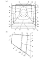
- FIG. 2A and 2B are diagrams showing a case according to the embodiment of the present invention, where FIG. 2A is a front view and FIG. 2B is a left sectional view.
- 21 is a top plate
- 22 is a bottom plate
- 23 is a left side plate
- 24 is a right side plate
- 25 is a back plate
- 26 is an opening side
- 27 is an upper flange
- 28 is a lower flange
- 29 is an upper corner
- 31 is an upper corner.
- Opening 32 is a notch, 33a, 33ba and 33bb are bent parts, 34 is a second waterproof wall, 35 is an opening, 36 is a notch, 37a, 37ba and 37bb are bent parts, and 38 is a sliding pin Openings for use 39a, 39b, 39c and 39d are screw holes, and the other reference numerals are the same as those in FIG. 3 is a view showing a case according to the embodiment of the present invention, in which (c) is a perspective view and (d) is a right side sectional view of a connector socket attached.
- 58 is a connector socket
- 59 is a locking part
- other reference numerals are the same as those in FIG.
- the case 20 has both a role of protecting the solenoid from wind and rain and a role of fixing and supporting the solenoid and the connector socket.
- the space for housing the solenoid and the connector socket is a top plate 21, a bottom plate 22, a left side plate 23, a right side plate 24, and Surrounded by a back plate 25.
- an upper flange 27 and a lower flange 28 are respectively provided above and below the opening side 26.
- the top plate 21 and the bottom plate 22 are formed to have a downward slope toward the opening side 26.
- the bottom plate 22 is 30 degrees or more. It has a steep slope. This is for discharging rainwater entering from the opening side 26 and dew condensation generated in the case 20 from the opening side. By making the bottom plate 22 steep, water droplets do not remain in the case 20. It is designed to be discharged promptly.
- the inclination angles of the top plate 21 and the bottom plate 22 are not limited to those shown in this embodiment, and can be appropriately changed according to the situation of the place where the charging device is installed.
- the left side plate 23 and the right side plate 24 are provided so as to approach the center of the back plate 25 as approaching the back plate 25 side. In other words, it is provided so as to approach the power supply plug 40 while being skewed.
- the bottom plate 22 is formed to be steeper than the top plate 21, and the left side plate 23 and the right side plate 24 are close to each other in the insertion direction of the power supply plug 40.
- the case 20 is formed in a horn shape as a whole. This is because when the door 12 of the charger main body 11 shown in FIG. 1 is opened and closed by reducing the volume of the case 20, for example, it contacts the board provided inside the charger main body 11 and prevents the opening and closing. It is for not to be.
- case 20 since the volume of case 20 becomes small, it contributes also to size reduction of the charger main body 11. Further, the case 20 prevents the door 12 from being opened and closed. Thereby, the lateral width of the door 12 can be reduced.
- the steep bottom plate 22 also has a role of facilitating the discharge of rainwater and the like. Note that only the left side plate 23 or the right side plate 24 may be provided so as to approach the center of the back plate 25 depending on the arrangement of what is provided inside the charger body 11. 24 may be provided in parallel to each other.
- the top plate or bottom plate of the case 20 may be horizontal.
- the case 20 is provided with a first waterproof wall 30 in the vicinity of the opening side 26 and further provided with a second waterproof wall 34 on the inside thereof.
- a back plate 25 is located on the innermost side of the case 20.
- the back plate 25 is inclined vertically or inward from the opening side 26 so as to prevent the wiring arranged near the lower side of the back plate 25 from getting wet with water droplets such as condensation.
- the first waterproof wall 30 is provided on the opening side 26 from the back plate 25, and the second waterproof wall 34 is provided between the first waterproof wall 30 and the back plate 25.
- the first waterproof wall 30 and the second waterproof wall 34 are inclined inward from the opening side 26.
- the first waterproof wall 30 and the second waterproof wall 34 are inclined in this way, and the rain that has fallen from the opening side 26 is caused by retreating the lower side of these waterproof walls to the inside of the case 20. This is to prevent further intrusion through the opening 31 or 35.
- the solenoid of the locking device is attached in the vicinity of the upper corner 29 of the top plate 21 which is most resistant to rain, and is further protected from rain by the first waterproof wall 30 and the second waterproof wall 34. .
- the first waterproof wall 30 may be omitted.
- the first waterproof wall 30 is omitted, and the second waterproof wall 34 is an open support member that supports a connector socket, for example, a belt-like shape.
- the metal plate material formed in (1) may be replaced with one assembled in a cross-beam shape.
- the first waterproof wall 30 and the second waterproof wall 34 may be provided vertically.
- the first waterproof wall 30 has an opening 31 for inserting the plug main body 41 of the power supply plug 40 shown in FIG. 1 at the center and a notch 32 at the center of the lower end.
- an opening 35 for fixing the connector socket is formed in the center, and a notch 36 is formed in the center of the lower end. Therefore, when water droplets such as dew condensation generated inside the case 20 or rainwater entering through the opening 31 or 35 drops on the bottom plate 22, it flows out from the opening side 26 through the notches 32 and 36.
- the first waterproof wall 30 is provided with bent portions 33a and bent portions 33ba and 33bb at the upper and lower ends, respectively.
- the bent portion 33ba and the bent portion 33bb are provided on both the left and right sides of the cutout portion 32, respectively. Further, the bent portion 33a and the bent portions 33ba and 33bb are fixed to the top plate 21 and the bottom plate 22 with screws (not shown), respectively.
- the second waterproof wall 34 is provided with a bent portion 37a and bent portions 37ba and 37bb.
- the bent portion 37ba and the bent portion 37bb are provided on both the left and right sides of the cutout portion 36, respectively. Further, the bent portion 37a is bent toward the opening 26 opposite to the other bent portions in order to prevent rainwater from entering through a slight gap with the top plate 21 and getting the solenoid of the locking device wet. .
- either direction may be sufficient as a bending direction.
- the second waterproof wall 34 has a sliding pin opening 38 and screw holes 39a, 39b, 39c and 39d formed around the opening 35.
- the sliding pin opening 38 is for inserting a sliding pin of a solenoid.
- the screw holes 39a, 39b, 39c and 39d are for attaching the connector socket 58 to the second waterproof wall 34. That is, as shown in FIG. 3D, the connector socket 58 is provided at a position facing the insertion direction of the power supply plug 40, and the second portion with the inner part inserted into the opening 35. Screwed to the waterproof wall 34.
- the connector socket 58 forms a concave locking portion 59 at a portion facing the top plate 21. The locking portion 59 locks the locking portion 45 of the power supply plug 40 when the locking portion 45 of the power supply plug 40 enters.
- FIG. 4A and 4B are diagrams showing the power supply plug according to the embodiment of the present invention, in which FIG. 4A is a right side view and FIG. 4B is a right side partial enlarged view.
- 42 is a power supply connector
- 42b is an upper end
- 43 is a swing pin
- 44 is a swing arm
- 45 is a locking portion
- 46 is a curved surface
- other symbols are the same as those in FIG.
- the power supply plug 40 is provided with a power supply connector 42 connected to a power receiving connector on the charged side such as an electric vehicle or an electric motorcycle at the tip of the plug body 41.
- a power supply connector 42 connected to a power receiving connector on the charged side such as an electric vehicle or an electric motorcycle at the tip of the plug body 41.
- a swing pin 43 is provided so as to protrude substantially in parallel with the attaching / detaching direction of the power supply plug 40 with respect to the power supply connector 42.
- the swing pin 43 is for locking the power supply plug 40 to the charger main body 11.
- the swing arm 44 swings about a fulcrum in the plug main body 41 (not shown) by pushing the lock button 47 with a finger as shown by the arrow in FIG.
- the locking portion 45 is also raised. If the power connector 42 of the power plug 40 is inserted into the connector socket 58 and the finger is released from the lock button 47 while the lock button 47 is kept pressed, the swing arm 44 swings and the locking portion 45 is connected to the connector socket. It will be in the state latched by 58 latching
- the surface of the locking portion 45 that contacts the connector socket 58 is formed as a curved surface 46. Therefore, even if the lock button 47 is not pushed when inserting, the curved surface 46 slides against the contact portion of the connector socket 58 and pushes up the swing arm 44, so that the power supply plug 40 can continue to be pushed into the connector socket 58.
- the locking portion 45 enters the locking portion 59 of the connector socket 58 and is locked.
- the locking portion 45 is formed in a claw shape, but the locking portion of the connector socket 58 may be formed in a claw shape and the locking portion 45 may be formed in a concave shape.
- FIG. 5A and 5B are diagrams showing the locking device according to the embodiment of the present invention, where FIG. 5A is a plan view, FIG. 5B is a right side view when the solenoid is not energized, and FIG. 5C is when the solenoid is energized. It is a right view.
- 50 is a locking device
- 51 is a solenoid
- 52 is a frame
- 52a is a bent portion
- 52b is a guide slit
- 53 is a spring
- 54 is a coil
- 55 is a guide pin
- 56 is a movable iron core
- 57 is sliding. It is a pin.
- FIG. 5A is a plan view
- FIG. 5B is a right side view when the solenoid is not energized
- FIG. 5C is when the solenoid is energized. It is a right view.
- 50 is a locking device
- 51 is a solenoid
- 52 is a frame
- 52a is
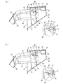
- FIG. 6 is a right side sectional view (1) showing the method for attaching and detaching the power supply plug according to the present invention, where (a) shows a state before starting the operation of pulling out the power supply plug, and (b) shows a state in which the solenoid is energized. .
- the reference numerals used in FIG. 6 are the same as those in FIGS.
- the locking device 50 includes a solenoid 51 and a sliding pin 57 and is disposed in the vicinity of the upper corner 29 of the top plate 21 of the case 20.
- the solenoid 51 is a so-called open frame solenoid, and is provided with a spring 53, a coil 54, a guide pin 55, a movable iron core 56 and the like with respect to the frame 52.
- the frame 52 is fixed to the top plate 21 with screws (not shown).
- the bent portion 52 a of the frame 52 guides the sliding pin 57.
- the coil 54 is energized, the movable iron core 56 is attracted to the fixed iron core inside the coil 54.
- a sliding pin 57 is connected to the tip of the movable iron core 56.
- the movable iron core 56 and the sliding pin 57 are integrally slid toward the coil 54 side. .
- the spring 53 returns the movable iron core 56 and the sliding pin 57 that are attracted to the coil 54 to their original positions when energization of the coil 54 is stopped.
- the guide pin 55 passes through the through holes of the movable iron core 56 and the sliding pin 57 and connects the movable iron core 56 and the sliding pin 57. Further, the lower end portion is provided so as to be positioned in the guide slit 52 b and guides the sliding of the movable iron core 56.
- a detection switch (not shown) is provided in the solenoid 51 so that the controller provided in the charger main body 11 detects the state of the sliding pin 57.
- This detection switch is interlocked with the pushing of the guide pin 55, and is configured to be kept on when the guide pin 55 is pushed.
- the detection switch may be provided at a place other than the inside of the solenoid 51.
- the slide pin 57 is disposed at a position opposite to the insertion direction of the power supply plug 40 in the lock mechanism of the present invention, the power supply plug 40 is bent to the slide pin 57 when the power supply plug 40 is attached to the case 20. There is no such thing as stress.
- FIG. 7 is a right sectional view (2) showing a method for attaching and detaching the power supply plug according to the present invention, where (c) shows a state in which the power supply plug is unlocked and (d) shows a state in which the power supply plug is pulled out.
- Reference numerals used in FIG. 7 are the same as those in FIG.
- FIG. 8 is a right side sectional view (3) showing the method for attaching and detaching the power supply plug according to the present invention. It is.
- the reference numerals used in FIG. 8 are the same as those in FIG.
- FIG. 9 is a flowchart showing a method of using the charging device.
- the power supply connector 42 of the power supply plug 40 is inserted into the connector socket 58 as shown in FIG. At this time, the locking portion 45 of the swing pin 43 is locked in a state of entering the locking portion 59 of the connector socket 58, and the power supply plug 40 is locked. Further, as shown in step 71 of FIG. 9, the solenoid 51 is not energized and is in a demagnetized state, and the sliding pin 57 is in contact with the swing arm 44. In addition, the detection switch is in the off state.
- the control unit of the charger main body 11 recognizes the start of use (step 72) and energizes the solenoid 51.
- step 73 When the solenoid 51 is excited (step 73), the movable iron core 56 and the sliding pin 57 are integrally slid toward the coil 54, and the state shown in FIG. 6B is obtained.
- the detection switch is turned on, and the control unit detects unlocking of the power supply plug 40 (step 74).
- the control unit displays an instruction to start charging on the display unit 14 (step 75). In this state, there is nothing that restricts the swing of the swing arm 44, and the lock button 47 can be pushed in as indicated by an arrow.
- step 76 When the user who sees this instruction pushes the lock button 47 as indicated by an arrow, as shown in FIG. 7C, the user swings so that the tip of the swing arm 44 is raised. Since the locking portion 45 of the swing pin 43 is separated from the locking portion 59 of the connector socket 58 and the power supply plug 40 is unlocked, as shown in FIG. Pull out. Then, the power supply plug 40 is inserted into a power receiving connector such as an electric vehicle (step 76), and an operation for starting charging is performed by the operation unit 15. Upon receiving this operation (step 77), the control unit demagnetizes the solenoid 51. The movable iron core 56 and the sliding pin 57 that have been attracted to the coil 54 return to their original positions. At this time, the detection switch is turned off (step 78).
- a power receiving connector such as an electric vehicle
- the user pulls out the power supply plug 40 from the power receiving connector of the electric vehicle or the like, and the user pushes the power supply plug 40 into the connector socket 58, as shown in FIG.
- the tip of the swing arm 44 and the tip of the sliding pin 57 come into contact with each other.
- the sliding pin 57 is pushed toward the coil 54 side.
- the detection switch is turned on (step 79).
- the locking portion 45 reaches the locking portion 59 of the connector socket 58, the locking portion 45 enters the recessed portion of the locking portion 59 and is locked.
- the sliding pin 57 is restored and the detection switch is turned off (step 80).
- the control unit recognizes that a series of operations related to the use of the charging device has been completed when detecting the detection switch OFF ⁇ ON ⁇ OFF.
- the flowchart shown in FIG. 9 shows an example of how to use the charging device. For example, another operation is performed such as displaying the estimated time until the end of power supply for the user after the start of power supply. Also good.
- FIG. 10 is a right side sectional view showing a modification of the case according to the embodiment of the present invention, where (a) is a first modification and (b) is a second modification.
- 60 is a case
- 61 is a top plate
- 62 is a bottom plate
- 63 is a back plate
- 64 is an opening side
- 65 is an upper flange
- 66 is a lower flange
- 67 is a first waterproof wall
- 68a and 68bb are bent.
- Reference numeral 69 denotes a second waterproof wall
- reference numerals 70a and 70bb denote bent parts, and other reference numerals are the same as those in FIG.
- FIG. 10A shows a modification in which one waterproof wall is provided.
- the charging device 10 when the charging device 10 is installed in a place with a shelter (roof), it is possible to considerably reduce the rain entering the case 20 by the shelter, and thus the first waterproof wall 30 may be omitted.
- FIG. 10B for example, when storing a device other than the locking device 50 and the connector socket 58 in the case 60, the space between the opening side 64 and the first waterproof wall 67, or The possibility of getting wet in the rain is smaller in the case of storing in the space between the back plate 63 and the second waterproof wall 69 than in storing in the space between the first waterproof wall 67 and the second waterproof wall 69.
- the top plate 61 and the bottom plate 62 of the case 60 are formed as parallel inclined surfaces, and the space between the back plate 63 and the second waterproof wall 69 is increased to facilitate storage.
- the upper flange 65 and the lower flange 66, the bent portions 68a and 68bb of the first waterproof wall 67, and the bent portions 70a and 70bb of the second waterproof wall 69 have the opposite bending directions. 2 and the case 20 of FIG.
- the slide pin 57 is disposed at a position facing the insertion direction of the power plug 40, the slide pin 57 is mounted when the power plug 40 is attached to the case 20. There is no stress applied to the 57. Furthermore, since the case 20 is not only a means for avoiding rain, but also a means for supporting the connector socket 58 and the locking device 50, the charger main body 11 can be reduced in size, and the charger main body 11 can be designed. Is not complicated.
- the slide pin 57 is provided at a position facing the insertion direction of the swing pin 43, the swing pin 43 pushes the slide pin 57 when the power supply plug 40 is inserted into the case, and the locking portion When 45 is locked to the locking portion 59, the sliding pin returns and the configuration in which the peripheral edge of the swing pin 43 contacts the peripheral edge of the sliding pin 57 can be easily realized. Furthermore, since the back plate 25 of the case 20 is inclined inward from the opening side 26, the thing provided near the front plate of the case is less likely to hit the rain. In addition, the top plate 21 and the bottom plate 22 are inclined so as to rise upward from the opening side toward the inside, so that rainwater and water droplets of dew condensation naturally flow out to the opening side.
- the left side plate 23 and the right side plate 24 are skewed so as to approach the center of the back plate 25 as they go inward from the opening side, the volume of the case 20 is reduced, and the charger is used when the door 12 is opened and closed. It is possible to prevent the door 12 from being opened and closed by touching what is provided in the main body 11 and to reduce the lateral width of the door 12.
- the first waterproof wall 30 and the second waterproof wall 34 are inclined vertically or inward from the opening side 26, most of the rainwater can be prevented from entering. Since the notch 32 and the notch 36 are respectively provided at the lower end portions of the first waterproof wall 30 and the second waterproof wall 34, it is possible to easily discharge rain and condensation water drops that have entered inside the waterproof wall. it can. Since the movable iron core 56 of the solenoid 51 is connected to the sliding pin 57, the control unit can appropriately control the sliding of the sliding pin 57 by switching between energization and non-energization of the solenoid 51.
- the swing pin 43 is not provided on the upper side of the power supply plug 40 but on the lower side, the left side, or the right side, and the sliding pin opening 38 of the second waterproof wall 34 is provided.
- the locking portion 59 of the connector socket 58 may also be provided on the side matched with this.
- both are formed in a claw shape, or one is formed in a ring shape and the other is Various shapes and configurations can be adopted, such as forming a hook shape.
Landscapes
- Engineering & Computer Science (AREA)
- Power Engineering (AREA)
- Transportation (AREA)
- Mechanical Engineering (AREA)
- Life Sciences & Earth Sciences (AREA)
- Sustainable Development (AREA)
- Sustainable Energy (AREA)
- Charge And Discharge Circuits For Batteries Or The Like (AREA)
- Details Of Connecting Devices For Male And Female Coupling (AREA)
- Electric Propulsion And Braking For Vehicles (AREA)
- Connector Housings Or Holding Contact Members (AREA)
Abstract
Description
11 充電器本体
12 扉
13 前面パネル
14 表示部
15 操作部
16 扉用錠
17 右側面パネル
18 背面パネル
19 左側面パネル
20 ケース
21 天板
22 底板
23 左側板
24 右側板
25 背板
26 開口側
27 上部フランジ
28 下部フランジ
29 上部隅
30 第1防水壁
31 開口部
32 切欠部
33a 折曲部
33ba 折曲部
33bb 折曲部
34 第2防水壁
35 開口部
36 切欠部
37a 折曲部
37ba 折曲部
37bb 折曲部
38 摺動ピン用開口部
39a ねじ孔
39b ねじ孔
39c ねじ孔
39d ねじ孔
40 給電プラグ
41 プラグ本体
42 給電コネクタ
42b 上端
43 揺動ピン
44 揺動アーム
45 係止部
46 曲面
47 ロックボタン
48 グリップ部
49 給電ケーブル
50 施錠装置
51 ソレノイド
52 フレーム
52a 折曲部
52b ガイドスリット
53 スプリング
54 コイル
55 ガイドピン
56 可動鉄心
57 摺動ピン
58 コネクタソケット
59 係止部
60 ケース
61 天板
62 底板
63 背板
64 開口側
65 上部フランジ
66 下部フランジ
67 第1防水壁
68a 折曲部
68bb 折曲部
69 第2防水壁
70a 折曲部
70bb 折曲部
90 充電装置
91 給電プラグ
92 施錠装置
93 摺動ピン
94 取り外しボタン
95 カバー
Claims (12)
- 充電器本体から給電ケーブルを介して給電プラグが接続されており、前記給電プラグを充電器本体の正面に設けたケースに差し込む構造を有する充電装置であって、
前記ケース内に、先端に係止部を備えたコネクタソケットと、
摺動ピンを備えた施錠装置と、を設け、
前記給電プラグに、前記コネクタソケットに保持される給電コネクタと、
先端に前記係止部に係止する係止部を備えた揺動ピンと、を設け、
前記給電プラグを前記ケースに差し込んで、前記給電コネクタが前記コネクタソケットに保持される際に、前記揺動ピンが前記摺動ピンを押し込み、前記給電プラグの前記係止部と前記ケースの前記係止部とが係止すると、前記摺動ピンが戻されて、前記揺動ピンの周縁が前記摺動ピンの周縁に当接して、前記給電プラグと前記ケースとを施錠するように構成していることを特徴とする充電装置。 - 前記摺動ピンは、前記揺動ピンの差込方向と対向する位置に設けられていることを特徴とする請求項1に記載の充電装置。
- 前記施錠装置を設置した前記ケースの背板は、開口側から垂直又は内側に向けて傾斜させていることを特徴とする請求項1または請求項2に記載の充電装置。
- 前記ケースの天板は、開口側から水平又は内側に向けて上り勾配になるように傾斜させていることを特徴とする請求項1から請求項3のいずれか一項に記載の充電装置。
- 前記ケースの底板は、開口側から水平又は内側に向けて上り勾配になるように傾斜させていることを特徴とする請求項1から請求項4のいずれか一項に記載の充電装置。
- 前記ケースの側板は、開口側から平行又は内側に向かうに従い背板の中心に近づくように斜行させていることを特徴とする請求項1から請求項5のいずれか一項に記載の充電装置。
- 前記ケース内且つ前記ケースの背板より開口側に第1防水壁を設けていることを特徴とする請求項1から請求項6のいずれか一項に記載の充電装置。
- 前記第1防水壁は、開口側から垂直又は内側に向けて傾斜させていることを特徴とする請求項7に記載の充電装置。
- 前記第1防水壁と前記ケースの背板との間に第2防水壁を設けていることを特徴とする請求項7または請求項8に記載の充電装置。
- 前記第2防水壁は、開口側から垂直又は内側に向けて傾斜させていることを特徴とする請求項9に記載の充電装置。
- 前記ケースは、前記第1防水壁と前記第2防水壁とのうち、少なくとも前記第1防水壁の下端部に水抜き用の切欠部が形成されていることを特徴とする請求項7から請求項10のいずれか一項に記載の充電装置。
- 前記施錠装置は、ソレノイドを備えており、前記摺動ピンは前記ソレノイドの可動鉄心と連接していることを特徴とする請求項1から請求項11のいずれか一項に記載の充電装置。
Priority Applications (5)
| Application Number | Priority Date | Filing Date | Title |
|---|---|---|---|
| JP2012554544A JP5567695B2 (ja) | 2011-11-18 | 2011-11-18 | 充電装置 |
| KR1020137008411A KR101418225B1 (ko) | 2011-11-18 | 2011-11-18 | 충전장치 |
| PCT/JP2011/076638 WO2013073049A1 (ja) | 2011-11-18 | 2011-11-18 | 充電装置 |
| CN201180050377.2A CN103329363B (zh) | 2011-11-18 | 2011-11-18 | 充电装置 |
| US13/992,703 US8961216B2 (en) | 2011-11-18 | 2011-11-18 | Charging apparatus |
Applications Claiming Priority (1)
| Application Number | Priority Date | Filing Date | Title |
|---|---|---|---|
| PCT/JP2011/076638 WO2013073049A1 (ja) | 2011-11-18 | 2011-11-18 | 充電装置 |
Publications (1)
| Publication Number | Publication Date |
|---|---|
| WO2013073049A1 true WO2013073049A1 (ja) | 2013-05-23 |
Family
ID=48429159
Family Applications (1)
| Application Number | Title | Priority Date | Filing Date |
|---|---|---|---|
| PCT/JP2011/076638 Ceased WO2013073049A1 (ja) | 2011-11-18 | 2011-11-18 | 充電装置 |
Country Status (5)
| Country | Link |
|---|---|
| US (1) | US8961216B2 (ja) |
| JP (1) | JP5567695B2 (ja) |
| KR (1) | KR101418225B1 (ja) |
| CN (1) | CN103329363B (ja) |
| WO (1) | WO2013073049A1 (ja) |
Cited By (7)
| Publication number | Priority date | Publication date | Assignee | Title |
|---|---|---|---|---|
| EP2712770A3 (en) * | 2012-09-28 | 2014-10-22 | Mitsubishi Jidosha Kogyo Kabushiki Kaisha | Charging connector accommodation apparatus for use in truck-type electric vehicle |
| JP2015133851A (ja) * | 2014-01-14 | 2015-07-23 | 矢崎エナジーシステム株式会社 | 車両用充電装置 |
| JP2017111898A (ja) * | 2015-12-15 | 2017-06-22 | 株式会社豊田自動織機 | 電池パック |
| WO2019145996A1 (ja) * | 2018-01-23 | 2019-08-01 | 三菱電機株式会社 | 充放電器、車両充放電システム、充電器及び車両充電システム |
| CN110370974A (zh) * | 2019-07-19 | 2019-10-25 | 新昌县云大农业有限公司 | 一种防止拔取的可移动电力新能源桩 |
| CN113555723A (zh) * | 2021-06-22 | 2021-10-26 | 化雷 | 一种户外防水充电枪 |
| US11318857B2 (en) * | 2019-11-01 | 2022-05-03 | Ford Global Technologies, Llc | System for hands-free electrified vehicle charging |
Families Citing this family (19)
| Publication number | Priority date | Publication date | Assignee | Title |
|---|---|---|---|---|
| JP5524926B2 (ja) * | 2011-10-07 | 2014-06-18 | 日産自動車株式会社 | 充電装置 |
| JP5878457B2 (ja) * | 2012-12-13 | 2016-03-08 | 株式会社東海理化電機製作所 | 充電ケーブルロック装置 |
| DE102013112991A1 (de) * | 2013-11-25 | 2015-06-11 | Phoenix Contact Gmbh & Co. Kg | Ladestecker zum Laden eines Elektrofahrzeugs |
| USD778818S1 (en) * | 2014-02-12 | 2017-02-14 | Abb Technology Ag | Charging station |
| USD733923S1 (en) * | 2014-02-18 | 2015-07-07 | Maurice Ento July | Unit |
| GB2557475B (en) * | 2015-06-24 | 2021-11-03 | Fisher & Paykel Healthcare Ltd | Breathing assistance apparatus |
| WO2018093622A1 (en) * | 2016-11-15 | 2018-05-24 | Eli Lilly And Company | Medication delivery device with mechanical locking system |
| JP6218994B1 (ja) * | 2016-11-28 | 2017-10-25 | 三菱電機株式会社 | 充電システム |
| US11404824B2 (en) | 2017-04-21 | 2022-08-02 | Harting Electric Stiftung & Co. Kg | Attachment housing arrangement and method for unlocking |
| DE102017215010B4 (de) * | 2017-08-28 | 2022-03-24 | Te Connectivity Germany Gmbh | Steckdose mit einem in Steckrichtung beweglichen Verriegelungselement |
| DE102017123207A1 (de) * | 2017-10-06 | 2019-04-11 | Kiekert Ag | Elektrische Anschlussvorrichtung |
| CN108990508A (zh) * | 2018-08-02 | 2018-12-14 | 苏州科瓴精密机械科技有限公司 | 智能机器人系统 |
| DE102018222676A1 (de) * | 2018-12-20 | 2020-06-25 | Robert Bosch Gmbh | Wechselakkupack für ein akkubetriebenes Gerät mit einer Schutzkappe |
| DE102019212431B3 (de) * | 2019-08-20 | 2020-11-19 | Volkswagen Aktiengesellschaft | Ladedose eines Elektro- oder Hybridfahrzeuges |
| CN111923763A (zh) * | 2020-07-08 | 2020-11-13 | 张佰行 | 一种新能源汽车充电桩 |
| KR102279219B1 (ko) * | 2021-03-30 | 2021-07-19 | 주식회사 한우리이엔지 | 충돌 방지기능 전기차 충전 스테이션 |
| US20230256845A1 (en) * | 2022-02-16 | 2023-08-17 | The StressCrete Group | Fully enclosed secure ev charging system |
| KR102703910B1 (ko) * | 2022-08-06 | 2024-09-06 | 채비(주) | 전기차 충전장치 |
| US20240075839A1 (en) * | 2022-09-07 | 2024-03-07 | GM Global Technology Operations LLC | Heated ev charge coupler |
Citations (8)
| Publication number | Priority date | Publication date | Assignee | Title |
|---|---|---|---|---|
| JPH07192806A (ja) * | 1993-12-24 | 1995-07-28 | Yazaki Corp | コネクタ構造 |
| JPH09161884A (ja) * | 1995-12-06 | 1997-06-20 | Yazaki Corp | 電気自動車の充電用コネクタ |
| JP2010259277A (ja) * | 2009-04-28 | 2010-11-11 | Nitto Electric Works Ltd | 電気自動車用充電スタンド |
| JP2011081952A (ja) * | 2009-10-05 | 2011-04-21 | Toyota Motor Corp | コネクタのロック機構 |
| JP2011087353A (ja) * | 2009-10-13 | 2011-04-28 | Panasonic Electric Works Co Ltd | 電気自動車用充電スタンド |
| JP2011165609A (ja) * | 2010-02-15 | 2011-08-25 | Tokai Rika Co Ltd | 給電プラグのロック構造 |
| JP2011181455A (ja) * | 2010-03-03 | 2011-09-15 | Panasonic Electric Works Co Ltd | 電気自動車用充電スタンド |
| JP2011243342A (ja) * | 2010-05-17 | 2011-12-01 | Tokai Rika Co Ltd | プラグロック構造 |
Family Cites Families (8)
| Publication number | Priority date | Publication date | Assignee | Title |
|---|---|---|---|---|
| JP2978348B2 (ja) * | 1992-12-18 | 1999-11-15 | 矢崎総業株式会社 | 給電コネクタ |
| DE19544942C2 (de) * | 1994-12-01 | 2001-12-06 | Yazaki Corp | Verbindungsvorrichtung mit einem Spannungszufuhrsteckverbinder und einem Spannungsaufnahmesteckverbinder und Verfahren zum Verbinden/Trennen einer Spannungszufuhreinrichtung |
| CN1153409A (zh) * | 1995-08-09 | 1997-07-02 | 住友电装株式会社 | 连接器用锁定装置及其在充电连接器和/或高压电缆连接器中的应用 |
| CN102044891A (zh) * | 2009-10-13 | 2011-05-04 | 松下电工株式会社 | 电动汽车用充电装置 |
| CN201674065U (zh) * | 2010-04-23 | 2010-12-15 | 张家港友诚科技机电有限公司 | 充电接口的防拔结构 |
| JP5486398B2 (ja) * | 2010-05-12 | 2014-05-07 | 株式会社東海理化電機製作所 | 給電プラグロック装置 |
| CN201741933U (zh) * | 2010-08-19 | 2011-02-09 | 南京康尼科技实业有限公司 | 充电连接器电磁锁锁固机构 |
| JP5645077B2 (ja) * | 2011-03-17 | 2014-12-24 | 住友電装株式会社 | 充電用コネクタ |
-
2011
- 2011-11-18 WO PCT/JP2011/076638 patent/WO2013073049A1/ja not_active Ceased
- 2011-11-18 CN CN201180050377.2A patent/CN103329363B/zh active Active
- 2011-11-18 KR KR1020137008411A patent/KR101418225B1/ko active Active
- 2011-11-18 JP JP2012554544A patent/JP5567695B2/ja active Active
- 2011-11-18 US US13/992,703 patent/US8961216B2/en active Active
Patent Citations (8)
| Publication number | Priority date | Publication date | Assignee | Title |
|---|---|---|---|---|
| JPH07192806A (ja) * | 1993-12-24 | 1995-07-28 | Yazaki Corp | コネクタ構造 |
| JPH09161884A (ja) * | 1995-12-06 | 1997-06-20 | Yazaki Corp | 電気自動車の充電用コネクタ |
| JP2010259277A (ja) * | 2009-04-28 | 2010-11-11 | Nitto Electric Works Ltd | 電気自動車用充電スタンド |
| JP2011081952A (ja) * | 2009-10-05 | 2011-04-21 | Toyota Motor Corp | コネクタのロック機構 |
| JP2011087353A (ja) * | 2009-10-13 | 2011-04-28 | Panasonic Electric Works Co Ltd | 電気自動車用充電スタンド |
| JP2011165609A (ja) * | 2010-02-15 | 2011-08-25 | Tokai Rika Co Ltd | 給電プラグのロック構造 |
| JP2011181455A (ja) * | 2010-03-03 | 2011-09-15 | Panasonic Electric Works Co Ltd | 電気自動車用充電スタンド |
| JP2011243342A (ja) * | 2010-05-17 | 2011-12-01 | Tokai Rika Co Ltd | プラグロック構造 |
Cited By (11)
| Publication number | Priority date | Publication date | Assignee | Title |
|---|---|---|---|---|
| EP2712770A3 (en) * | 2012-09-28 | 2014-10-22 | Mitsubishi Jidosha Kogyo Kabushiki Kaisha | Charging connector accommodation apparatus for use in truck-type electric vehicle |
| US9333868B2 (en) | 2012-09-28 | 2016-05-10 | Mitsubishi Jidosha Kogyo Kabushiki Kaisha | Charging connector accommodation apparatus for use in truck-type electric vehicle |
| JP2015133851A (ja) * | 2014-01-14 | 2015-07-23 | 矢崎エナジーシステム株式会社 | 車両用充電装置 |
| JP2017111898A (ja) * | 2015-12-15 | 2017-06-22 | 株式会社豊田自動織機 | 電池パック |
| WO2019145996A1 (ja) * | 2018-01-23 | 2019-08-01 | 三菱電機株式会社 | 充放電器、車両充放電システム、充電器及び車両充電システム |
| CN110370974A (zh) * | 2019-07-19 | 2019-10-25 | 新昌县云大农业有限公司 | 一种防止拔取的可移动电力新能源桩 |
| CN110370974B (zh) * | 2019-07-19 | 2020-12-22 | 深圳特来电新能源有限公司 | 一种防止拔取的可移动电力新能源桩 |
| US11318857B2 (en) * | 2019-11-01 | 2022-05-03 | Ford Global Technologies, Llc | System for hands-free electrified vehicle charging |
| US11981224B2 (en) | 2019-11-01 | 2024-05-14 | Ford Global Technologies, Llc | System for hands-free electrified vehicle charging with connector attachment mechanism |
| CN113555723A (zh) * | 2021-06-22 | 2021-10-26 | 化雷 | 一种户外防水充电枪 |
| CN113555723B (zh) * | 2021-06-22 | 2022-06-17 | 康思立达(上海)汽车科技有限公司 | 一种户外防水充电枪 |
Also Published As
| Publication number | Publication date |
|---|---|
| JPWO2013073049A1 (ja) | 2015-04-02 |
| US20130309898A1 (en) | 2013-11-21 |
| KR20130088854A (ko) | 2013-08-08 |
| KR101418225B1 (ko) | 2014-07-09 |
| JP5567695B2 (ja) | 2014-08-06 |
| US8961216B2 (en) | 2015-02-24 |
| CN103329363B (zh) | 2015-11-25 |
| CN103329363A (zh) | 2013-09-25 |
Similar Documents
| Publication | Publication Date | Title |
|---|---|---|
| JP5567695B2 (ja) | 充電装置 | |
| CN104169122B (zh) | 电动车辆的充电端口控制装置 | |
| JP5796208B2 (ja) | コンセントユニット | |
| US9120391B2 (en) | Security system for electric vehicle charging equipment | |
| US20080290671A1 (en) | Handle apparatus | |
| JP6249756B2 (ja) | 充電コネクター用ホルダー | |
| US7484702B2 (en) | Temporary clamping structure for electronics | |
| CN103248086A (zh) | 在为电力供能车辆充电时使用的充电站 | |
| JP5934579B2 (ja) | 電気自動車充電コンセント装置 | |
| JP2015042056A (ja) | 電気自動車用の2台同時充電可能な充電スタンド | |
| KR102673107B1 (ko) | 차량용 콘센트 조립체 | |
| KR200455528Y1 (ko) | 통신 보안 시스템 박스 | |
| JP5383729B2 (ja) | 屋外コンセント保護用カバー | |
| JP2013151201A (ja) | 車両のドア装置 | |
| JP4915941B2 (ja) | 電気機器収納箱の扉の蝶番構造 | |
| JP5476164B2 (ja) | 電気自動車用充電スタンド | |
| JP2011101451A (ja) | 電気自動車用充電スタンド | |
| JP6730494B1 (ja) | 蝶番、及び蝶番を備えたキャビネット | |
| JP4740044B2 (ja) | 機器収納キャビネット | |
| JP5553401B2 (ja) | 自動車用充電装置 | |
| CN220682178U (zh) | 一种电动车共享充电桩 | |
| JP2013045687A (ja) | コンセント | |
| JP6035532B2 (ja) | 車両用充電装置 | |
| JP2010168772A (ja) | 壁取り付け型機器 | |
| JP4979728B2 (ja) | コンセント装置 |
Legal Events
| Date | Code | Title | Description |
|---|---|---|---|
| ENP | Entry into the national phase |
Ref document number: 2012554544 Country of ref document: JP Kind code of ref document: A |
|
| ENP | Entry into the national phase |
Ref document number: 20137008411 Country of ref document: KR Kind code of ref document: A |
|
| 121 | Ep: the epo has been informed by wipo that ep was designated in this application |
Ref document number: 11876013 Country of ref document: EP Kind code of ref document: A1 |
|
| WWE | Wipo information: entry into national phase |
Ref document number: 13992703 Country of ref document: US |
|
| NENP | Non-entry into the national phase |
Ref country code: DE |
|
| 122 | Ep: pct application non-entry in european phase |
Ref document number: 11876013 Country of ref document: EP Kind code of ref document: A1 |