WO2013069352A1 - コネクタ - Google Patents
コネクタ Download PDFInfo
- Publication number
- WO2013069352A1 WO2013069352A1 PCT/JP2012/071063 JP2012071063W WO2013069352A1 WO 2013069352 A1 WO2013069352 A1 WO 2013069352A1 JP 2012071063 W JP2012071063 W JP 2012071063W WO 2013069352 A1 WO2013069352 A1 WO 2013069352A1
- Authority
- WO
- WIPO (PCT)
- Prior art keywords
- tool
- bolt
- fitting
- housing
- electric wire
- Prior art date
- Legal status (The legal status is an assumption and is not a legal conclusion. Google has not performed a legal analysis and makes no representation as to the accuracy of the status listed.)
- Ceased
Links
Images





Classifications
-
- H—ELECTRICITY
- H01—ELECTRIC ELEMENTS
- H01R—ELECTRICALLY-CONDUCTIVE CONNECTIONS; STRUCTURAL ASSOCIATIONS OF A PLURALITY OF MUTUALLY-INSULATED ELECTRICAL CONNECTING ELEMENTS; COUPLING DEVICES; CURRENT COLLECTORS
- H01R13/00—Details of coupling devices of the kinds covered by groups H01R12/70 or H01R24/00 - H01R33/00
- H01R13/62—Means for facilitating engagement or disengagement of coupling parts or for holding them in engagement
- H01R13/621—Bolt, set screw or screw clamp
-
- H—ELECTRICITY
- H01—ELECTRIC ELEMENTS
- H01R—ELECTRICALLY-CONDUCTIVE CONNECTIONS; STRUCTURAL ASSOCIATIONS OF A PLURALITY OF MUTUALLY-INSULATED ELECTRICAL CONNECTING ELEMENTS; COUPLING DEVICES; CURRENT COLLECTORS
- H01R13/00—Details of coupling devices of the kinds covered by groups H01R12/70 or H01R24/00 - H01R33/00
- H01R13/56—Means for preventing chafing or fracture of flexible leads at outlet from coupling part
-
- H—ELECTRICITY
- H01—ELECTRIC ELEMENTS
- H01R—ELECTRICALLY-CONDUCTIVE CONNECTIONS; STRUCTURAL ASSOCIATIONS OF A PLURALITY OF MUTUALLY-INSULATED ELECTRICAL CONNECTING ELEMENTS; COUPLING DEVICES; CURRENT COLLECTORS
- H01R43/00—Apparatus or processes specially adapted for manufacturing, assembling, maintaining, or repairing of line connectors or current collectors or for joining electric conductors
- H01R43/26—Apparatus or processes specially adapted for manufacturing, assembling, maintaining, or repairing of line connectors or current collectors or for joining electric conductors for engaging or disengaging the two parts of a coupling device
Definitions
- the present invention relates to a connector.
- Patent Document 1 a housing in which an electric wire is led out from an electric wire lead-out surface, an electric wire cover attached to the housing so as to cover the electric wire lead-out surface, and a housing fitted by being screwed with a tool are fitted.
- a connector having a bolt assembled to a mating partner is disclosed.
- the bolt is accommodated inside the electric wire cover so as to be positioned in the vicinity of the electric wire outlet surface, and the electric wire cover is formed with an insertion port for inserting a tool into the electric wire cover.
- the tool inserted into the wire cover from the insertion port is fitted to the bolt and rotated.
- the electric wire cover has an opening / closing door formed in the insertion opening, and when the tool is inserted into the insertion opening, the opening / closing door is pushed open with the tool. Therefore, the tool always contacts the open / close door while the bolt is screwed.
- the tool should be fitted coaxially with the bolt, but if the tool axis is tilted with respect to the bolt axis and the tilt angle is not large, the tool fits into the bolt. Therefore, it is possible to screw a bolt. When the bolt is screwed in while the tool is inclined, the tool turns on a constant path around the axis of the bolt.
- the present invention has been completed based on the above situation, and an object of the present invention is to prevent the electric wire cover from being adversely affected by tool interference.
- the connector of the present invention includes a housing in which an electric wire is led out from an electric wire lead-out surface, an electric wire cover that is attached to the housing and covers the electric wire lead-out surface, and is screwed with a tool from the outer surface side of the electric wire cover.
- Bolt for assembling the housing to the mating member, and the outer wall surface of the electric wire cover are recessed so that the tool can be inserted, and the bottom is a cylindrical shape in which a fitting portion of the bolt with the tool is arranged And an angle formed between the axis of the bolt and the axis of the tool, which is formed in the cylindrical portion and intersects with the fitting portion as a substantially fulcrum, the screw of the bolt is screwed into the fitting portion by the tool.
- An interference portion that causes the tool to interfere with the wire cover only when the fitting portion and the tool are at an angle at which the tool cannot be fitted beyond a possible fitting range. Having the features.
- the tool cannot be removed from the fitting part and screwed in. As it does not turn in a constant orbit. Therefore, even if the tool comes into contact with the interference part, the pressing action from the tool to the electric wire cover including the interference part is slight, and the electric wire cover is not likely to be adversely affected by the interference of the tool. If the tool is not tilted with respect to the axis of the bolt and the tool cannot be removed from the fitting part, the tool turns on a fixed path as the bolt is screwed in, but the tool contacts the interference part. Not done. Therefore, in this case as well, there is no possibility that the wire cover is adversely affected by the interference of the tool.
- Preferred embodiments of the present invention are as follows. Immediately after the tool is able to be screwed into the fitting portion, the tool interferes with the interference portion. If it carries out like this, when a tool interferes with an interference part, since the screwing operation
- the cylindrical portion has a tapered shape such that the diameter dimension becomes smaller as it is closer to the wire lead-out surface. In this way, when the wire cover is assembled to the housing, the tapered tapered tubular portion scrapes the plurality of wires led out from the wire lead-out surface, so that the tubular portion and the wire lead-out surface There is no risk that the electric wire will be caught between them.
- the inner peripheral surface of the cylindrical portion increases in diameter from an inclined surface that decreases in diameter as it approaches the wire lead-out surface, and an opening edge that faces the wire lead-out surface from an inner bottom portion that is most reduced in diameter on the inclined surface. And a sub-inclined surface. Since the cylindrical portion has an inclined surface, a large work space for operating the tool can be secured. Moreover, since the cylindrical part has a sub-inclined surface, the fitting part can be smoothly guided inside the cylindrical part in the process of assembling the electric wire cover.
- the housing is formed with a through-hole through which the bolt penetrates, and the through-hole is disposed inside a mounting cylinder protruding from the wire lead-out surface, and the fitting part is disposed at an opening end of the mounting cylinder Can be stopped when screwing is completed, and the outer peripheral surface of the mounting cylinder part and the sub-inclined surface of the cylindrical part are arranged to face each other with a gap in the radial direction.
- the water enters the electric wire cover, the water enters the gap and is guided to the bottom side of the electric wire cover along the sub-inclined surface. For this reason, it is prevented that water permeates into the through hole of the mounting cylinder part, and the sealing property in the through hole of the mounting cylinder part can be kept good.
- the opening end of the mounting cylinder portion is located at the same height as the inclined portion of the sub inclined surface in the axial direction of the bolt. Therefore, the water that has entered the electric wire cover is prevented from adhering to the opening end of the mounting cylinder part, and the sealing performance in the through hole of the mounting cylinder part can be kept better.
- a terminal housing chamber into which a terminal fitting can be inserted is formed in the housing, and a rubber plug is attached to the terminal fitting, and the terminal housing chamber is liquid-tightly sealed by the rubber plug. Thereby, the water guided to the bottom side of the electric wire cover by the sub-inclined surface is also prevented from entering the housing.
- the interference portion is formed over the entire circumference of the inner peripheral surface of the cylindrical portion. Therefore, even if the tool removed from the fitting portion is displaced at any rotation angle, the state of interfering with the interference portion is ensured.
- the interference part is formed in an area farthest from the wire lead-out surface of the cylindrical part. According to this, it becomes possible to visually recognize that the tool has come off the fitting portion.
- a rib extending along the axial direction of the bolt is formed at a position back-to-back with the interference portion on the outer peripheral surface of the cylindrical portion.
- the connector 10 of this embodiment includes a first housing 11 made of a synthetic resin (a housing that is a constituent element of the present invention) in which a plurality of wires 13 are led out from a wire lead-out surface 12, A synthetic resin wire cover 30 that is attached to one housing 11 and covers the wire lead-out surface 12, and is screwed with a tool 21 from the outer surface side of the wire cover 30, whereby the first housing 11 is moved to the second housing 23 (the present invention). And a bolt 17 to be assembled to a mating member).
- a synthetic resin a housing that is a constituent element of the present invention
- first terminal accommodating chambers 14 are formed inside the first housing 11 so as to vertically penetrate the first housing 11 with the wire lead-out surface 12 facing upward.
- a first terminal fitting 15 is inserted into each first terminal accommodating chamber 14 from above the first housing 11 (on the back side of the first housing 11).
- the electric wires 13 connected to the first terminal fittings 15 are led upward from the electric wire lead-out surface 12 (back surface) of the first housing 11.
- the first housing 11 is formed with a through hole 16 that vertically penetrates the central portion of the electric wire outlet surface 12.
- the bolt 17 includes a cylindrical main body 18, a hexagonal fitting part 19 (see FIG. 6) formed coaxially at the upper end of the main body 18, and coaxially downward from the lower end of the main body 18. It is comprised from the external thread part 20 extended.
- the bolt 17 has its main body 18 facing the through hole 16 with its axis 17A directed in the vertical direction (the direction in which both the housings 11 and 23 are fitted and the direction in which the electric wire cover 30 is assembled to the first housing 11). It is attached in the state fitted in.
- the attached bolt 17 is in a state in which relative displacement in the vertical direction is restricted with respect to the first housing 11 and rotation about the axis 17A is allowed.
- the fitting part 19 is arrange
- the male screw portion 20 protrudes downward from the front surface (lower surface) of the first housing 11.
- the bolt 17 is rotated by using an elongated tool 21 whose outer peripheral shape is a cylindrical shape.
- a hexagonal fitting hole 22 is formed coaxially on the inner periphery of the tip of the tool 21 (the lower end when fitted to the fitting portion 19).
- the fitting hole 22 of the tool 21 is fitted to the fitting portion 19, when the operation force in the rotation direction about the axis 21 ⁇ / b> A is applied to the tool 21, the tool 21 and the bolt 17 are integrated. It is designed to rotate.
- the second housing 23 has a plurality of second terminal accommodation chambers 24 corresponding to the first terminal accommodation chambers 14 of the first housing 11.
- a second terminal fitting 25 is accommodated in the second terminal accommodating chamber 24.
- a nut 26 is attached to the second housing 23 so as to correspond to the through hole 16 of the first housing 11 coaxially.
- the nut 26 attached to the second housing 23 is fixed in a state in which relative displacement in the axial direction (vertical direction) and rotation around the axial line are restricted with respect to the second housing 23.
- the electric wire cover 30 is configured by integrally forming a cover main body 31 and a guide portion 36.
- the cover main body 31 is configured to rise upward from the outer peripheral edge of the wire lead-out surface 12 (in a direction away from the wire lead-out surface 12) in a state where the wire cover 30 is attached to the first housing 11.
- the outer peripheral wall portion 32 has a shape in which a part thereof in the circumferential direction is cut out, and a lead-out port 35 for leading the electric wire 13 turned in the electric wire cover 30 to the outside of the electric wire cover 30 is formed. Yes.
- the guide portion 36 extends from the upper edge portion of the opening edge of the outlet 35 to the outside of the wire cover main body 31. The electric wire 13 led out from the lead-out port 35 is taped along the guide portion 36.
- the cylindrical part 34 has a form in which the outer surface of the cover main body 31 (the electric wire cover 30) is recessed, and the recessed space serves as a work space 37 into which the tool 21 can be inserted.
- the fitting portion 19 is coaxially disposed on the bottom portion 38 (lower end portion) of the cylindrical portion 34 (work space 37). Between the outer periphery of the fitting part 19 and the inner peripheral surface of the cylindrical part 34, the clearance for accommodating the tool 21 in the state fitted on the fitting part 19 is ensured.
- the inner diameter dimension of the cylindrical portion 34 (work space 37) is minimum at the lower end (bottom 38) and maximum at the upper end. That is, the cylindrical portion 34 has a tapered shape in which the diameter dimension becomes smaller as the distance from the wire lead-out surface 12 becomes closer. And the upper end part in the inner periphery of the cylindrical part 34 (the opening edge part of the work space 37 on the outer surface of the electric wire cover 30 and the area farthest from the wire lead-out surface 12 in the cylindrical part 34) is on the entire periphery.
- An annular interference part 39 is formed. The technical significance of the interference unit 39 is as follows.
- the tool 21 should be fitted coaxially with the bolt 17. However, even if the axis 21 ⁇ / b> A of the tool 21 is inclined with respect to the axis 17 ⁇ / b> A of the bolt 17, If the inclination angle is not large, the tool 21 is fitted into the fitting portion 19 of the bolt 17, so that the bolt 17 can be screwed. When the bolt 17 is screwed while the tool 21 is inclined, the tool 21 turns in a constant path around the axis 17A of the bolt 17 in the work space 37.
- the tool 21 When such a turning motion occurs in the work space 37 (in the cylindrical portion 34), the tool 21 excessively presses the inner periphery of the cylindrical portion 34, so that the cylindrical portion 34 or the cylindrical shape in the electric wire cover 30 is used. There is a concern that an area other than the portion 34 may be illegally deformed or damaged.
- the angle formed by the axis 17A of the bolt 17 and the axis 21A of the tool 21 intersecting at the fitting portion 19 is As shown in FIG. 5, when the fitting part 19 and the tool 21 are at an angle at which the fitting part 19 and the tool 21 cannot be fitted beyond the range in which the tool 21 can be fitted into the fitting part 19 so that the bolt 17 can be screwed. Only in this way, the tool 21 interferes (contacts) with the interference part 39.
- the tool 21 comes to interfere with the interference portion 39 immediately after the tool 21 is able to be screwed into the fitting portion 19 from the state where the tool 21 can be screwed into the non-fitting state. ing.
- the tool 21 is in contact with a flange 52 (described later) at one end in the radial direction, and the other end in the radial direction is positioned at the upper end of the fitting portion 19. So as to be inclined.
- the angle formed between the axis 17 ⁇ / b> A of the bolt 17 and the axis 21 ⁇ / b> A of the tool 21 intersecting at the fitting portion 19 is relatively small, and the tool 21 is connected to the fitting portion 19 with respect to the bolt 17.
- the tool 21 does not interfere (contact) with the interference portion 39 when it is within a range where the screw can be fitted.
- the wire cover 30 is not likely to be adversely affected by the interference of the tool 21.
- the cylindrical portion 34 has a tapered shape in which the diameter dimension becomes smaller as it is closer to the wire lead-out surface 12. Therefore, when the electric wire cover 30 is assembled while being moved parallel to the housing so as to approach the electric wire outlet surface 12 from above, as shown in FIG. A plurality of electric wires 13 led out from the surface 12 are scraped. Therefore, there is no possibility that the electric wire 13 is caught between the tubular portion 34 and the electric wire outlet surface 12.
- the inner circumferential surface of the cylindrical portion 34 has an inclined surface 57 that decreases in a taper shape as it goes to the lower end side (the wire lead-out surface 12 side), and the most reduced diameter in the inclined surface 57. It consists of a sub-inclined surface 58 that expands in a curved shape from the inner bottom portion to the lower end opening edge of the bottom portion 38 (opening edge facing the wire lead-out surface 12).
- the bottom portion 38 of the cylindrical portion 34 has a thin shape toward the lower end side due to the sub-inclined surface 58.
- the cylindrical portion 34 has the inclined surface 57, a large working space 37 can be secured, and the bolt 17 can be shortened. Moreover, since the cylindrical part 34 has the sub-inclined surface 58, the fitting part 19 of the volt
- the first housing 11 is formed with a cylindrical mounting tube portion 51 that protrudes upward from the wire lead-out surface 12.
- the through hole 16 is disposed inside the mounting cylinder portion 51.
- a flange 52 is formed on the outer periphery of the lower end of the fitting portion 19 so as to extend over the entire circumference. As shown in FIG. 9, when the flange 52 abuts on the upper end opening edge 53 of the mounting cylinder portion 51, further tightening of the bolt 17 is prevented.
- the outer peripheral surface of the mounting cylinder portion 51 and the sub-inclined surface 58 have a lap region that faces each other in the radial direction in a state where the electric wire cover 30 is assembled.
- a radial gap 55 is formed between the surface and the sub-inclined surface 58.
- the gap 55 is configured to expand from the open end of the mounting cylinder portion 51 toward the base end side, which is the wire lead-out surface 12 side.
- the opening end of the mounting cylinder portion 51 is located at the same height as the inclined portion of the sub inclined surface 58 in the vertical direction.
- the first terminal fitting 15 is provided with a rubber plug 60 fitted to the terminal portion of the electric wire 13, and the rubber plug 60 is liquid-tight in the first terminal accommodating chamber 14. Contained. For this reason, the water that has reached the electric wire outlet surface 12 through the auxiliary inclined surface 58 is prevented from entering the first housing 11 by the rubber plug 60.
- first ribs 40 are formed on the outer peripheral surface of the cylindrical portion 34 (the surface facing the wire lead-out surface 12) at a position back to the interference portion 39.
- the 1st rib 40 is extended in the up-down direction in the several places spaced apart in the circumferential direction among the outer peripheral surfaces of the cylindrical part 34.
- the wire cover 30 is also formed with a second rib 41 along the inner surface of the upper wall portion 33 and the inner surface of the outer peripheral wall portion 32.
- the present invention is not limited to the embodiments described with reference to the above description and drawings.
- the following embodiments are also included in the technical scope of the present invention.
- the interference part was distribute
- the cross-sectional shape that intersects the axis of the cylindrical part is circular, but the cross-sectional shape that intersects the axis of the cylindrical part may be a polygon.
- the cylindrical portion is tapered, but the cylindrical portion may have a constant diameter.
Landscapes
- Details Of Connecting Devices For Male And Female Coupling (AREA)
Abstract
電線カバーが工具の干渉に起因する悪影響を受けるのを防止する。 コネクタ(10)は、第1ハウジング(11)の電線導出面(12)を覆う電線カバー(30)と、電線カバー(30)の外面側から工具(21)でねじ込み操作されるボルト(17)と、電線カバー(30)の外壁面を凹ませて工具(21)の挿入を可能とした形態であり、底部(38)にはボルト(17)における工具(21)との嵌合部(19)が配される筒状部(34)と、筒状部(34)に形成され、嵌合部(19)を略支点として交差するボルト(17)の軸線(17A)と工具(21)の軸線(21A)とのなす角度が、嵌合部(19)に対し工具(21)がボルト(17)のねじ込みを可能に嵌合し得る範囲を超えて嵌合部(19)と工具とが嵌合不能な角度であるときにのみ、工具(21)を電線カバー(30)に干渉させる干渉部(39)とを備える。
Description
本発明は、コネクタに関するものである。
特許文献1には、電線導出面から電線を導出させたハウジングと、電線導出面を覆うようにハウジングに取り付けられた電線カバーと、ハウジングに設けられ、工具でねじ込み操作されることでハウジングを嵌合相手に組み付けるボルトとを備えたコネクタが開示されている。ボルトは、電線導出面の近傍に位置するように、電線カバーの内部に収容されており、電線カバーには、工具を電線カバーの内部に挿入するための挿入口が形成されている。ボルトをねじ込む際には、挿入口から電線カバー内に差し込んだ工具を、ボルトに嵌合して回転させる。
上記の電線カバーには、挿入口に開閉扉が形成されており、挿入口に工具を挿入する際には、開閉扉を工具で押し開くようになっている。したがって、ボルトのねじ込みを行う間、工具は、常に、開閉扉に接触することになる。工具は、本来、ボルトに対し同軸状に嵌合されるべきであるが、工具の軸線がボルトの軸線に対して傾斜していても、その傾斜角度が大きくなければ、工具はボルトに嵌合されるため、ボルトをねじ込むことが可能である。工具を斜めにしたままボルトをねじ込む場合、工具は、ボルトの軸線を中心として一定の軌道で旋回することになる。このような旋回運動が生じると、工具が開閉扉を過剰に押圧するため、開閉扉や、電線カバーのうち開閉扉を支持している部分等に不正な変形や破損を来すことが懸念される。
本発明は上記のような事情に基づいて完成されたものであって、電線カバーが工具の干渉に起因する悪影響を受けるのを防止することを目的とする。
本発明は上記のような事情に基づいて完成されたものであって、電線カバーが工具の干渉に起因する悪影響を受けるのを防止することを目的とする。
本発明のコネクタは、電線導出面から電線を導出させたハウジングと、前記ハウジングに取り付けられて前記電線導出面を覆う電線カバーと、前記電線カバーの外面側から工具でねじ込み操作されることにより前記ハウジングを相手部材に組み付けるボルトと、前記電線カバーの外壁面を凹ませて前記工具の挿入を可能とした形態であり、底部には前記ボルトにおける前記工具との嵌合部が配される筒状部と、前記筒状部に形成され、前記嵌合部を略支点として交差する前記ボルトの軸線と前記工具の軸線とのなす角度が、前記嵌合部に対し前記工具が前記ボルトのねじ込みを可能に嵌合し得る範囲を超えて前記嵌合部と前記工具とが嵌合不能な角度であるときにのみ、前記工具を前記電線カバーに干渉させる干渉部とを備えているところに特徴を有する。
工具の軸線とボルトの軸線とのなす角度が大きくなって、工具が電線カバーの干渉部に干渉すると、工具が嵌合部から外れてボルトをねじ込むことができないので、工具がボルトの軸線を中心として一定の軌道で旋回することはない。したがって、工具が干渉部に接触しても、工具から干渉部を含む電線カバーへの押圧作用は軽微であり、電線カバーは工具の干渉に起因する悪影響を受ける虞がない。また、ボルトの軸線に対する工具の傾きが小さくて、工具が嵌合部から外れない場合は、ボルトがねじ込まれるのに伴って工具が一定の軌道で旋回するのであるが、工具は干渉部に接触していない。したがって、この場合も、電線カバーは工具の干渉に起因する悪影響を受ける虞がない。
本発明の好ましい形態は、次の通りである。
前記嵌合部に対し前記工具が前記ボルトのねじ込みを可能に嵌合し得る状態から嵌合不能な状態になった直後に、前記工具が前記干渉部と干渉する。こうすると、工具が干渉部と干渉したときに、ボルトのねじ込み作業を早い段階で中止することができるため、電線カバーが工具によって損傷するのをより確実に防止することができる。
前記嵌合部に対し前記工具が前記ボルトのねじ込みを可能に嵌合し得る状態から嵌合不能な状態になった直後に、前記工具が前記干渉部と干渉する。こうすると、工具が干渉部と干渉したときに、ボルトのねじ込み作業を早い段階で中止することができるため、電線カバーが工具によって損傷するのをより確実に防止することができる。
前記筒状部は、前記電線導出面に近いほど径寸法が小さくなるような先細りのテーパ状をなしている。こうすると、電線カバーをハウジングに組み付ける際には、先細りのテーパ状をなす筒状部が、電線導出面から導出された複数本の電線を掻き分けていくので、筒状部と電線導出面との間に電線が噛み込む虞はない。
前記筒状部の内周面は、前記電線導出面に近づくにしたがって縮径する傾斜面と、前記傾斜面における最も縮径された内底部から前記電線導出面と対向する開口縁にかけて拡径する副傾斜面とを有している。筒状部が傾斜面を有しているため、工具の操作を行うための作業空間を大きく確保することができる。また、筒状部が副傾斜面を有しているため、電線カバーの組み付け過程で、筒状部の内側に嵌合部を円滑に誘い込むことができる。
前記ハウジングには、前記ボルトが貫通する貫通孔が形成され、前記貫通孔は、前記電線導出面から突出する装着筒部の内部に配置され、前記装着筒部の開口端には前記嵌合部がねじ込み完了時に当て止め可能とされており、前記装着筒部の外周面と前記筒状部の前記副傾斜面とは、径方向に隙間を開けつつ互いに対向して配置される。電線カバー内に水が浸入すると、該水が隙間に入り込み、副傾斜面に沿いつつ電線カバーの底側に誘導される。このため、装着筒部の貫通孔内に水が浸入するのが防止され、装着筒部の貫通孔内のシール性を良好に保つことができる。
前記装着筒部の開口端が、前記ボルトの軸線方向において、前記副傾斜面の傾斜部分と同じ高さに位置している。したがって、電線カバー内に浸入した水が装着筒部の開口端に付着するのが回避され、装着筒部の貫通孔内のシール性をより良好に保つことができる。
前記ハウジングには端子金具を挿入可能な端子収容室が形成され、前記端子金具にはゴム栓が取り付けられ、前記ゴム栓によって前記端子収容室内が液密にシールされる。これにより、副傾斜面によって電線カバーの底側に誘導された水がハウジング内に浸入するのも防止される。
前記干渉部が前記筒状部の内周面の全周に亘って形成されている。これにより、嵌合部から外れた工具が如何なる回転角度で変位していても干渉部に干渉する状態が担保される。
前記干渉部が、前記筒状部のうち前記電線導出面から最も遠い領域に形成されている。これによれば、工具が嵌合部から外れたことを視覚的にも認識することが可能となる。
前記筒状部の外周面における前記干渉部と背合わせの位置に、前記ボルトの軸線方向に沿って延びるリブが形成されている。これにより、工具が干渉部と干渉しても、電線カバーが不正に変形するのがより確実に防止される。
<実施例1>
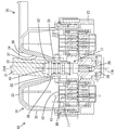
以下、本発明を具体化した実施例1を図1~図9を参照して説明する。図2に示すように、本実施例のコネクタ10は、電線導出面12から複数本の電線13を導出させた合成樹脂製の第1ハウジング11(本発明の構成要件であるハウジング)と、第1ハウジング11に取り付けられて電線導出面12を覆う合成樹脂製の電線カバー30と、電線カバー30の外面側から工具21でねじ込み操作されることにより第1ハウジング11を第2ハウジング23(本発明の構成要件である相手部材)に組み付けるボルト17とを備えて構成されている。
以下、本発明を具体化した実施例1を図1~図9を参照して説明する。図2に示すように、本実施例のコネクタ10は、電線導出面12から複数本の電線13を導出させた合成樹脂製の第1ハウジング11(本発明の構成要件であるハウジング)と、第1ハウジング11に取り付けられて電線導出面12を覆う合成樹脂製の電線カバー30と、電線カバー30の外面側から工具21でねじ込み操作されることにより第1ハウジング11を第2ハウジング23(本発明の構成要件である相手部材)に組み付けるボルト17とを備えて構成されている。
図1,2に示すように、第1ハウジング11の内部には、電線導出面12を上向きにした状態において第1ハウジング11を上下に貫通する複数の第1端子収容室14が形成されている。各第1端子収容室14内には、第1ハウジング11の上方(第1ハウジング11の背面側)から第1端子金具15が挿入されている。各第1端子金具15に接続された電線13は、第1ハウジング11の電線導出面12(背面)から上方へ導出されている。第1ハウジング11には、電線導出面12の中央部を上下に貫通する貫通孔16が形成されている。
ボルト17は、円柱形の本体部18と、本体部18の上端に同軸状に形成した六角形をなす嵌合部19(図6を参照)と、本体部18の下端から下方へ同軸状に延出する雄ネジ部20とから構成されている。ボルト17は、その軸線17Aを上下方向(両ハウジング11,23の嵌合方向及び第1ハウジング11に対する電線カバー30の組付け方向と略平行な方向)に向けて、本体部18を貫通孔16に嵌合させた状態で取り付けられている。取り付けられたボルト17は、第1ハウジング11に対し、上下方向への相対変位を規制され、且つ軸線17Aを中心とする回転を許容された状態となっている。嵌合部19は、電線導出面12(上面)の上方へ突出した位置に配置されている。雄ネジ部20は、第1ハウジング11の正面(下面)から下方へ突出されている。
図3~5に示すように、ボルト17は、外周形状が円柱形をなす細長い工具21を用いて回転される。工具21の先端部(嵌合部19に嵌合した状態では下端部)内周には、六角形の嵌合孔22が同軸状に形成されている。工具21の嵌合孔22を嵌合部19に嵌合した状態で、工具21に対し、その軸線21Aを中心とする回転方向の操作力を付与すると、工具21とボルト17が一体となって回転するようになっている。
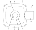
図1に示すように、第2ハウジング23は、第1ハウジング11の第1端子収容室14と対応する複数の第2端子収容室24を有する。第2端子収容室24には第2端子金具25が収容されている。第2ハウジング23には、第1ハウジング11の貫通孔16と同軸状に対応するようにナット26が取り付けられている。第2ハウジング23に取り付けられたナット26は、第2ハウジング23に対し軸線方向(上下方向)における相対変位及び軸線周りの回転を規制された状態に固定されている。
第1ハウジング11と第2ハウジング23を嵌合する際には、両ハウジング11,23を浅く嵌合して、ボルト17の雄ネジ部20をナット26に少し挿入する。この状態で、ボルト17の嵌合部19に対し、上方から工具21を同軸状に嵌合し、工具21に回転操作力を加えてボルト17を回転させる。すると、ボルト17がナット26にねじ込まれることにより、両ハウジング11,23が接近し、図2,3に示す嵌合状態となる。
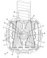
図1,7,8に示すように、電線カバー30は、カバー本体31と、ガイド部36とを一体に形成して構成されている。図2に示すように、カバー本体31は、電線カバー30を第1ハウジング11に取り付けた状態において電線導出面12の外周縁から上方(電線導出面12から遠ざかる方向)へ立ち上がるような形態となる外周壁部32と、外周壁部32の上端縁に連なる環状の上壁部33と、上壁部33の内周縁から下方(電線導出面12に近づく方向)へ延出する円筒状の筒状部34とから構成されている。外周壁部32には、その周方向における一部を切欠した形態であって、電線カバー30内で転向させられた電線13を電線カバー30の外部へ導出させるための導出口35が形成されている。ガイド部36は、導出口35の開口縁のうち上縁部から電線カバー本体31の外方へ延出している。導出口35から導出される電線13は、ガイド部36に沿わせてテープ巻きされる。
筒状部34は、カバー本体31(電線カバー30)の外面を凹ませた形態であり、その凹んだ空間は、工具21が挿入可能な作業空間37となっている。電線カバー30を第1ハウジング11に取り付けた状態では、筒状部34(作業空間37)の底部38(下端部)に嵌合部19が同軸状に配置されている。嵌合部19の外周と筒状部34の内周面との間には、工具21を嵌合部19に外嵌した状態で収容するためのクリアランスが確保されている。
筒状部34(作業空間37)の内径寸法は、下端部(底部38)において最小であり、上端部において最大である。つまり、筒状部34は、電線導出面12に近いほど径寸法が小さくなるような先細りのテーパ状をなしている。そして、筒状部34の内周における上端部(電線カバー30の外面における作業空間37の開口縁部であって、筒状部34のうち電線導出面12から最も遠い領域)は、全周に亘り、円環状の干渉部39となっている。この干渉部39の技術的意義は、次の通りである。
工具21は、本来、図3に示すように、ボルト17に対し同軸状に嵌合されるべきであるが、工具21の軸線21Aがボルト17の軸線17Aに対して傾斜していても、その傾斜角度が大きくなければ、工具21はボルト17の嵌合部19に嵌合されるため、ボルト17をねじ込むことが可能である。工具21を斜めにしたままボルト17をねじ込んだ場合、工具21は、作業空間37内でボルト17の軸線17Aを中心として一定の軌道で旋回することになる。このような旋回運動が作業空間37内(筒状部34内)で生じると、工具21が筒状部34の内周を過剰に押圧するため、筒状部34や、電線カバー30における筒状部34以外の領域等に不正な変形や破損を来すことが懸念される。
そこで、本実施例では、ボルト17が嵌合部19を略支点として不正な姿勢に傾いた場合に、嵌合部19で交差するボルト17の軸線17Aと工具21の軸線21Aとのなす角度が、図5に示すように、嵌合部19に対し工具21がボルト17のねじ込みを可能に嵌合し得る範囲を超えて嵌合部19と工具21とが嵌合不能な角度になったときにのみ、工具21が干渉部39と干渉(接触)するようになっている。具体的には、嵌合部19に対し工具21がボルト17のねじ込みを可能に嵌合し得る状態から嵌合不能な状態になった直後に、工具21が干渉部39と干渉するようになっている。この場合、工具21は、図5に示すように、径方向一端がフランジ52(後述する)に当接し、その当接位置を支点として、径方向他端が嵌合部19の上端に位置するように、傾いて配置される。
このように、工具21の軸線21Aとボルト17の軸線17Aとのなす角度が大きくなって、工具21が電線カバー30の干渉部39に干渉すると、工具21が嵌合部19から外れてボルト17をねじ込むことができないので、工具21をどのように操作しても、工具21がボルト17の軸線を中心として一定の軌道で旋回することはない。したがって、工具21が干渉部39に接触しても、工具21から干渉部39を含む電線カバー30への押圧作用は軽微であり、電線カバー30は工具21の干渉に起因する悪影響を受ける虞がない。
また、図4に示すように、嵌合部19で交差するボルト17の軸線17Aと工具21の軸線21Aとのなす角度が、比較的小さくて、嵌合部19に対し工具21がボルト17のねじ込みを可能に嵌合し得る範囲内である場合には、工具21は干渉部39と干渉(接触)しない。この状態では、ボルト17がねじ込まれるのに伴って工具21がボルト17の軸線を中心として一定の軌道で旋回するのであるが、工具21は干渉部39に接触していない。したがって、この場合、電線カバー30は工具21の干渉に起因する悪影響を受ける虞がない。
また、本実施例で、筒状部34が、電線導出面12に近いほど径寸法が小さくなるような先細りのテーパ状をなしている。したがって、電線カバー30をハウジングに対し上方から電線導出面12に接近させるように平行移動させながら組み付ける際には、図6に示すように、先細りのテーパ状をなす筒状部34が、電線導出面12から導出された複数本の電線13を掻き分けていく。したがって、筒状部34と電線導出面12との間に電線13が噛み込む虞はない。
また、筒状部34の内周面は、図9に示すように、下端側(電線導出面12側)へ行くにしたがってテーパ状に縮径する傾斜面57と、傾斜面57における最も縮径された内底部から底部38の下端開口縁(電線導出面12と対向する開口縁)にかけて曲面状に拡径する副傾斜面58とからなる。筒状部34の底部38は、副傾斜面58によって下端側ほど薄肉の形態になっている。
筒状部34が傾斜面57を有することにより、作業空間37を大きく確保することができ、かつボルト17を短くすることができる。また、筒状部34が副傾斜面58を有することにより、電線カバー30の組み付け時にボルト17の嵌合部19が底部38の内側に円滑に誘い込まれることになる。このため、底部38の下端開口縁がボルト17の嵌合部19と干渉して底部38が損傷するのが防止される。
さらに、第1ハウジング11には、図1に示すように、電線導出面12から上方に突出する円筒状の装着筒部51が形成されている。貫通孔16は、装着筒部51の内部に配置されている。また、嵌合部19の下端外周には、フランジ52が全周に亘って張り出し形成されている。図9に示すように、フランジ52が装着筒部51の上端開口縁53に当接することにより、ボルト17のそれ以上の締め付けが阻止されるようになっている。
図9に示すように、電線カバー30が組み付けられた状態で、装着筒部51の外周面と副傾斜面58とは、径方向において互いに対向するラップ領域を有し、装着筒部51の外周面と副傾斜面58との間には、径方向の隙間55が形成されている。具体的には、隙間55は、装着筒部51の開口端から電線導出面12側となる基端側に向けて拡開する形態とされている。また、装着筒部51の開口端は、上下方向において、副傾斜面58の傾斜部分と同じ高さに位置している。このため、仮に、作業空間37に水が浸入しても、該水は、隙間55に入り込み、装着筒部51の開口端に付着することなく、副傾斜面58を伝って電線カバー30の底側に誘導されるようになっている。したがって、装着筒部51とフランジ52との間に水が入り込むのが防止され、装着筒部51の貫通孔16内のシール性を良好に維持することが可能となっている。なお、図2に示すように、第1端子金具15には電線13の端末部に嵌着されたゴム栓60が取り付けられており、ゴム栓60は第1端子収容室14内に液密に収容されている。このため、副傾斜面58を通して電線導出面12に到達した水は、ゴム栓60によって第1ハウジング11内に浸入するのが防止される。
また、筒状部34の外周面(電線導出面12と対向する面)には、図1,8に示すように、干渉部39と背合わせの位置に、4本の第1リブ40が形成されている。第1リブ40は、筒状部34の外周面のうち周方向に間隔を空けた複数箇所において上下方向に延びている。また、電線カバー30には、第1リブ40の他に、上壁部33の内面及び外周壁部32の内面に沿った第2リブ41も形成されている。これらのリブ40,41により、筒状部34を含む電線カバー30の全体の強度が高められているので、工具21等の他部材が電線カバー30に干渉しても、電線カバー30の不正な変形等が防止される。
<他の実施例>
本発明は上記記述及び図面によって説明した実施例に限定されるものではなく、例えば次のような実施例も本発明の技術的範囲に含まれる。
(1)上記実施例では、干渉部を、筒状部における開口縁部に配したが、干渉部の位置は、筒状部における底部に近い位置であってもよい。
(2)上記実施例では、筒状部の軸線と交差する断面形状を円形としたが、筒状部の軸線と交差する断面形状は、多角形であってもよい。
(3)上記実施例では、筒状部をテーパ状としたが、筒状部は径寸法が一定であってもよい。
本発明は上記記述及び図面によって説明した実施例に限定されるものではなく、例えば次のような実施例も本発明の技術的範囲に含まれる。
(1)上記実施例では、干渉部を、筒状部における開口縁部に配したが、干渉部の位置は、筒状部における底部に近い位置であってもよい。
(2)上記実施例では、筒状部の軸線と交差する断面形状を円形としたが、筒状部の軸線と交差する断面形状は、多角形であってもよい。
(3)上記実施例では、筒状部をテーパ状としたが、筒状部は径寸法が一定であってもよい。
10…コネクタ
11…第1ハウジング(ハウジング)
12…電線導出面
13…電線
17…ボルト
17A…ボルトの軸線
19…嵌合部
21…工具
21A…工具の軸線
23…第2ハウジング(相手部材)
30…電線カバー
34…筒状部
38…筒状部の底部
39…干渉部
51…装着筒部
55…隙間
57…傾斜面
58…副傾斜面
11…第1ハウジング(ハウジング)
12…電線導出面
13…電線
17…ボルト
17A…ボルトの軸線
19…嵌合部
21…工具
21A…工具の軸線
23…第2ハウジング(相手部材)
30…電線カバー
34…筒状部
38…筒状部の底部
39…干渉部
51…装着筒部
55…隙間
57…傾斜面
58…副傾斜面
Claims (10)
- 電線導出面から電線を導出させたハウジングと、
前記ハウジングに取り付けられて前記電線導出面を覆う電線カバーと、
前記電線カバーの外面側から工具でねじ込み操作されることにより前記ハウジングを相手部材に組み付けるボルトと、
前記電線カバーの外壁面を凹ませて前記工具の挿入を可能とした形態であり、底部には前記ボルトにおける前記工具との嵌合部が配される筒状部と、
前記筒状部に形成され、前記嵌合部を略支点として交差する前記ボルトの軸線と前記工具の軸線とのなす角度が、前記嵌合部に対し前記工具が前記ボルトのねじ込みを可能に嵌合し得る範囲を超えて前記嵌合部と前記工具とが嵌合不能な角度であるときにのみ、前記工具を前記電線カバーに干渉させる干渉部とを備えていることを特徴とするコネクタ。 - 前記嵌合部に対し前記工具が前記ボルトのねじ込みを可能に嵌合し得る状態から嵌合不能な状態になった直後に、前記工具が前記干渉部と干渉することを特徴とする請求項1記載のコネクタ。
- 前記筒状部は、前記電線導出面に近いほど径寸法が小さくなるような先細りのテーパ状をなしていることを特徴とする請求項1又は2記載のコネクタ。
- 前記筒状部の内周面は、前記電線導出面に近づくにしたがって縮径する傾斜面と、前記傾斜面における最も縮径された内底部から前記電線導出面と対向する開口縁にかけて拡径する副傾斜面とを有していることを特徴とする請求項3記載のコネクタ。
- 前記ハウジングには、前記ボルトが貫通する貫通孔が形成され、前記貫通孔は、前記電線導出面から突出する装着筒部の内部に配置され、前記装着筒部の開口端には前記嵌合部がねじ込み完了時に当て止め可能とされており、前記装着筒部の外周面と前記筒状部の前記副傾斜面とは、径方向に隙間を開けつつ互いに対向して配置されることを特徴とする請求項4記載のコネクタ。
- 前記装着筒部の開口端が、前記ボルトの軸線方向において、前記副傾斜面の傾斜部分と同じ高さに位置していることを特徴とする請求項5記載のコネクタ。
- 前記ハウジングには端子金具を挿入可能な端子収容室が形成され、前記端子金具にはゴム栓が取り付けられ、前記ゴム栓によって前記端子収容室内が液密にシールされることを特徴とする請求項5又は6記載のコネクタ。
- 前記干渉部が、前記筒状部の内周面の全周に亘って形成されていることを特徴とする請求項1ないし7のいずれか1項記載のコネクタ。
- 前記干渉部が、前記筒状部のうち前記電線導出面から最も遠い領域に形成されていることを特徴とする請求項1ないし8のいずれか1項記載のコネクタ。
- 前記筒状部の外周面における前記干渉部と背合わせの位置に、前記ボルトの軸線方向に沿って延びるリブが形成されていることを特徴とする請求項1ないし9のいずれか1項記載のコネクタ。
Applications Claiming Priority (4)
| Application Number | Priority Date | Filing Date | Title |
|---|---|---|---|
| JP2011245982 | 2011-11-09 | ||
| JP2011-245982 | 2011-11-09 | ||
| JP2012-077793 | 2012-03-29 | ||
| JP2012077793A JP2013122900A (ja) | 2011-11-09 | 2012-03-29 | コネクタ |
Publications (1)
| Publication Number | Publication Date |
|---|---|
| WO2013069352A1 true WO2013069352A1 (ja) | 2013-05-16 |
Family
ID=48289738
Family Applications (1)
| Application Number | Title | Priority Date | Filing Date |
|---|---|---|---|
| PCT/JP2012/071063 Ceased WO2013069352A1 (ja) | 2011-11-09 | 2012-08-21 | コネクタ |
Country Status (2)
| Country | Link |
|---|---|
| JP (1) | JP2013122900A (ja) |
| WO (1) | WO2013069352A1 (ja) |
Cited By (2)
| Publication number | Priority date | Publication date | Assignee | Title |
|---|---|---|---|---|
| CN111326912A (zh) * | 2018-12-17 | 2020-06-23 | 住友电装株式会社 | 连接器嵌合体 |
| CN112703641A (zh) * | 2018-08-21 | 2021-04-23 | 株式会社自动网络技术研究所 | 电线盖及带电线盖连接器 |
Families Citing this family (3)
| Publication number | Priority date | Publication date | Assignee | Title |
|---|---|---|---|---|
| JP6191915B2 (ja) * | 2013-10-29 | 2017-09-06 | 住友電装株式会社 | コネクタ |
| JP6620938B2 (ja) * | 2016-04-11 | 2019-12-18 | 住友電装株式会社 | コネクタ |
| JP7006577B2 (ja) * | 2018-12-17 | 2022-01-24 | 住友電装株式会社 | コネクタ嵌合体 |
Citations (4)
| Publication number | Priority date | Publication date | Assignee | Title |
|---|---|---|---|---|
| JPH06236783A (ja) * | 1993-02-10 | 1994-08-23 | Yazaki Corp | 多極コネクタの嵌合認識構造 |
| JPH1074558A (ja) * | 1996-08-30 | 1998-03-17 | Kansei Corp | 防水コネクタ |
| JP2001135419A (ja) * | 1999-11-09 | 2001-05-18 | Auto Network Gijutsu Kenkyusho:Kk | シールドケーブルの端末処理方法及び端末処理構造 |
| JP2004079487A (ja) * | 2002-08-22 | 2004-03-11 | Ryosei Electro-Circuit Systems Ltd | 電気コネクタの防水構造 |
Family Cites Families (1)
| Publication number | Priority date | Publication date | Assignee | Title |
|---|---|---|---|---|
| US5871373A (en) * | 1996-02-23 | 1999-02-16 | Labinal Components And Systems, Inc. | Electrical connector |
-
2012
- 2012-03-29 JP JP2012077793A patent/JP2013122900A/ja active Pending
- 2012-08-21 WO PCT/JP2012/071063 patent/WO2013069352A1/ja not_active Ceased
Patent Citations (4)
| Publication number | Priority date | Publication date | Assignee | Title |
|---|---|---|---|---|
| JPH06236783A (ja) * | 1993-02-10 | 1994-08-23 | Yazaki Corp | 多極コネクタの嵌合認識構造 |
| JPH1074558A (ja) * | 1996-08-30 | 1998-03-17 | Kansei Corp | 防水コネクタ |
| JP2001135419A (ja) * | 1999-11-09 | 2001-05-18 | Auto Network Gijutsu Kenkyusho:Kk | シールドケーブルの端末処理方法及び端末処理構造 |
| JP2004079487A (ja) * | 2002-08-22 | 2004-03-11 | Ryosei Electro-Circuit Systems Ltd | 電気コネクタの防水構造 |
Cited By (2)
| Publication number | Priority date | Publication date | Assignee | Title |
|---|---|---|---|---|
| CN112703641A (zh) * | 2018-08-21 | 2021-04-23 | 株式会社自动网络技术研究所 | 电线盖及带电线盖连接器 |
| CN111326912A (zh) * | 2018-12-17 | 2020-06-23 | 住友电装株式会社 | 连接器嵌合体 |
Also Published As
| Publication number | Publication date |
|---|---|
| JP2013122900A (ja) | 2013-06-20 |
Similar Documents
| Publication | Publication Date | Title |
|---|---|---|
| WO2013069352A1 (ja) | コネクタ | |
| JP5733573B2 (ja) | 機器用コネクタ | |
| EP2644910B1 (en) | Connector connecting bolt, connector and connector assembly | |
| JP6709513B2 (ja) | 端子台 | |
| US20240088613A1 (en) | Connector | |
| JP6709511B2 (ja) | 開口封止部材及び電気機器 | |
| CN110336145A (zh) | 插入式连接器壳体 | |
| JP6873171B2 (ja) | ケーブル実装アセンブリ | |
| CN104640743B (zh) | 配线装置 | |
| JP5631225B2 (ja) | 中継コネクタ | |
| JP4417274B2 (ja) | シールドコネクタ | |
| JP2008010339A (ja) | コネクタ | |
| JP6071649B2 (ja) | 電気的素子のシール構造 | |
| JP5683257B2 (ja) | 中継コネクタ | |
| JP2015005417A (ja) | コネクタ | |
| JP6191915B2 (ja) | コネクタ | |
| JP2017153868A (ja) | 美容器 | |
| JP5543637B1 (ja) | コネクタ | |
| JP6082648B2 (ja) | コネクタ | |
| JP6096599B2 (ja) | コネクタ装置 | |
| JP2015097147A (ja) | コネクタ | |
| JP5978163B2 (ja) | コネクタ装置 | |
| JP6757811B2 (ja) | プラグ接触アセンブリ | |
| JP5129658B2 (ja) | 端子防水構造を備えたスタータモータ | |
| JP2010232130A (ja) | コネクタ付き蓋の接続構造 |
Legal Events
| Date | Code | Title | Description |
|---|---|---|---|
| 121 | Ep: the epo has been informed by wipo that ep was designated in this application |
Ref document number: 12848175 Country of ref document: EP Kind code of ref document: A1 |
|
| NENP | Non-entry into the national phase |
Ref country code: DE |
|
| 122 | Ep: pct application non-entry in european phase |
Ref document number: 12848175 Country of ref document: EP Kind code of ref document: A1 |