WO2013065593A1 - ドアロック装置 - Google Patents
ドアロック装置 Download PDFInfo
- Publication number
- WO2013065593A1 WO2013065593A1 PCT/JP2012/077713 JP2012077713W WO2013065593A1 WO 2013065593 A1 WO2013065593 A1 WO 2013065593A1 JP 2012077713 W JP2012077713 W JP 2012077713W WO 2013065593 A1 WO2013065593 A1 WO 2013065593A1
- Authority
- WO
- WIPO (PCT)
- Prior art keywords
- stopper
- divided body
- lever
- case
- lock lever
- Prior art date
- Legal status (The legal status is an assumption and is not a legal conclusion. Google has not performed a legal analysis and makes no representation as to the accuracy of the status listed.)
- Ceased
Links
Images












Classifications
-
- E—FIXED CONSTRUCTIONS
- E05—LOCKS; KEYS; WINDOW OR DOOR FITTINGS; SAFES
- E05B—LOCKS; ACCESSORIES THEREFOR; HANDCUFFS
- E05B77/00—Vehicle locks characterised by special functions or purposes
- E05B77/36—Noise prevention; Anti-rattling means
- E05B77/38—Cushion elements, elastic guiding elements or holding elements, e.g. for cushioning or damping the impact of the bolt against the striker during closing of the wing
-
- E—FIXED CONSTRUCTIONS
- E05—LOCKS; KEYS; WINDOW OR DOOR FITTINGS; SAFES
- E05B—LOCKS; ACCESSORIES THEREFOR; HANDCUFFS
- E05B81/00—Power-actuated vehicle locks
- E05B81/12—Power-actuated vehicle locks characterised by the function or purpose of the powered actuators
- E05B81/16—Power-actuated vehicle locks characterised by the function or purpose of the powered actuators operating on locking elements for locking or unlocking action
-
- E—FIXED CONSTRUCTIONS
- E05—LOCKS; KEYS; WINDOW OR DOOR FITTINGS; SAFES
- E05B—LOCKS; ACCESSORIES THEREFOR; HANDCUFFS
- E05B83/00—Vehicle locks specially adapted for particular types of wing or vehicle
- E05B83/36—Locks for passenger or like doors
-
- E—FIXED CONSTRUCTIONS
- E05—LOCKS; KEYS; WINDOW OR DOOR FITTINGS; SAFES
- E05B—LOCKS; ACCESSORIES THEREFOR; HANDCUFFS
- E05B85/00—Details of vehicle locks not provided for in groups E05B77/00 - E05B83/00
- E05B85/02—Lock casings
-
- E—FIXED CONSTRUCTIONS
- E05—LOCKS; KEYS; WINDOW OR DOOR FITTINGS; SAFES
- E05B—LOCKS; ACCESSORIES THEREFOR; HANDCUFFS
- E05B81/00—Power-actuated vehicle locks
- E05B81/02—Power-actuated vehicle locks characterised by the type of actuators used
- E05B81/04—Electrical
- E05B81/06—Electrical using rotary motors
Definitions
- the present invention relates to a door lock device that is fixed to a vehicle door and locks and unlocks the door.
- the assembling range when the lock lever is assembled is limited between the lock position and the unlock position by the stopper portion, so that it resists the biasing force of the elastic member.
- the lock lever had to be assembled, and the assembly workability was poor.
- the present invention has been made in view of the above circumstances, and an object thereof is to provide a door lock device capable of improving the workability of assembling a lock lever.
- a door lock device is provided with a support case adapted to be fixed to a door of a vehicle, and disposed in the support case, and includes a lock position and an unlock position.
- a lock lever adapted to lock and unlock the door by rotating between, a stopper portion provided in the support case, a stopper abutting portion provided in the lock lever, and the lock lever in the lock position
- An elastic member that urges away from an intermediate position with respect to the unlock position, and presses the stopper contact portion of the lock lever against the stopper portion of the support case at the lock position or the unlock position by the urging force.
- the case includes a first case divided body that rotatably supports the lock lever and elastically deforms the elastic member, and a second case having a stopper portion.
- the split body is formed by uniting in the rotation axis direction of the lock lever, provided in the first case split body, and in cooperation with the elastic member in a state where the first case split body and the second case split body are separated. Holds the lock lever in a standby position where the lock lever does not receive the urging force from the elastic member and the stopper contact portion faces the stopper portion in the rotation axis direction.
- first case divided body and the second case divided body and are engaged with each other so as to restrict the lateral displacement between the first case divided body and the second case divided body during the uniting process, and the stopper contact Of the first case divided body and the second case divided body, provided in one of the stopper portion and the stopper abutting portion, and the united guide for maintaining the portion and the stopper portion facing each other in the rotation axis direction
- the stopper guide which moves to the locked position or unlocked position.
- the combined guides engage with each other before the stopper guide provided on one of the stopper portion and the stopper contact portion slides on the other.
- the combined guides engage with each other before the stopper guide provided on one of the stopper portion and the stopper contact portion slides on the other.
- an arc hole centering around the rotation center of the lock lever is formed through the lock lever, and an opening edge at one end of the arc hole Is used as a stopper abutment, and a cylindrical stopper projection that protrudes from the second case segment and enters the arc hole is used as a stopper, and a tapered surface is formed at the tip of the cylindrical stopper projection.
- a guide post that protrudes from the first case divided body and slides and engages inside the cylindrical stopper projection during the uniting process, and the guide column and the cylindrical stopper projection are joined together. It has the characteristics.
- the rotation center hole formed through the rotation center of the lock lever and the first case divided body project from the rotation center hole and are inserted into the rotation center hole.
- the rotation center hole formed through the rotation center of the lock lever and the first case divided body project from the rotation center hole and are inserted into the rotation center hole.
- an interlocking rotating component that rotates in conjunction with the lock lever is pivotally supported. It has the characteristics.
- the support case that rotatably supports the lock lever unites the first case divided body and the second case divided body in the rotation axis direction of the lock lever.
- the first case divided body supports a lock lever and an elastic member that urges the lock lever, and the second case divided body locks the lock lever against the urging force of the elastic member.
- a stopper portion is provided to be received at the position or the unlock position.
- the lock lever When the lock lever is assembled to the first case divided body, the lock lever is assembled at the standby position where it does not receive the urging force from the elastic member, and is held at the standby position by the elastic member and the standby position holding portion. Further, in the process of combining the first case divided body and the second case divided body, the lateral displacement between the first case divided body and the second case divided body is restricted by the engagement of the combined guide provided thereon, and the standby position. The stopper abutting portion of the lock lever held by the stopper and the stopper portion of the second case divided body are maintained in a state of facing each other in the rotation axis direction of the lock lever.
- the stopper guide provided in one of the stopper portion and the stopper abutting portion is in sliding contact with the other side and presses the lock lever against the elastic member Turn to. That is, the lock lever held at the standby position with respect to the first case divided body moves from the standby position to the locked position or the unlocked position in the process of combining the first case divided body and the second case divided body. .
- the stopper portion is provided in the second case divided body, and the lock lever is provided in the first case divided body.
- the lock lever can be assembled at a standby position where it does not receive a biasing force from the elastic member. That is, it becomes unnecessary to assemble the lock lever against the urging force of the elastic member as in the prior art, and the workability of assembling the lock lever is improved.
- the cylindrical stopper projection protruding from the second case divided body is an arc hole formed through the lock lever.
- the taper surface formed at the tip of the cylindrical stopper protrusion slides into contact with the opening edge of one end of the arc hole so that the lock lever moves from the standby position to the locked position or unlocked position. And move.
- the guide column protruding from the first case division body is slidably engaged with the inside of the cylindrical stopper projection, so that the first case division body and the second case division body in the coalescence process. Side shift is regulated.
- the cylindrical stopper protrusion can be used as both the stopper and the united guide.
- the axial support column protruding from the second case divided body is slidably engaged inside the cylindrical shaft support protrusion protruding from the first case divided body and rotatably supporting the lock lever.
- the cylindrical shaft support protrusion can be supported at both ends in the axial direction, and rigidity can be ensured.
- the guide column as a united guide provided in the first case divided body can be used as the rotation shaft portion that pivotally supports the interlocking rotation component.
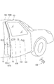
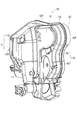
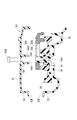
- the front view of the door lock device concerning one embodiment of the present invention.
- a perspective view of a part of the vehicle Perspective view of the inside of the vehicle door Side view of door lock device Rear view of the door lock device Side view of door lock device in unlatched state
- Side view of latched door lock device Side view of lift lever, open link, etc.
- Side view of lift lever, open link, etc. Side view of lift lever, open link, etc.
- Front view of motor, active lever, etc. assembled to first case division
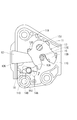
- the perspective view of the door lock apparatus of the state which removed the 1st case division body Front view of a part of the locked door lock device Front view of an enlarged part of the unlocked door lock device Sectional view taken along the line XX in FIG.
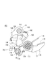
- FIG. 1 is a cross-sectional view taken along the line YY in FIG. Front view of the door lock device with the second case divided body removed Sectional drawing of the door lock apparatus of the state which removed the 2nd case division body Sectional view of the door lock device in the process of uniting the case divisions Sectional view of the door lock device in the process of uniting the case divisions
- the door lock device 10 of the present embodiment is configured such that a plurality of parts are rotatably supported on a support body 11 (see FIG. 3B) bent substantially at a right angle. Then, the first outer surface 11A (see FIG. 3A) on the one side of the bent portion of the support body 11 is rotated at the rotary door 101 disposed on the right side of the vehicle 100 as shown in FIG. 2A, for example. It is fixed to the end wall 101A opposite to the moving center by being addressed from the inner surface.
- a striker receiving groove 12 extending in the horizontal direction is opened on the first outer surface 11 ⁇ / b> A of the support body 11.
- a striker receiving port 12K at one end of the striker receiving groove 12 opens in the second outer surface 11B (see FIG. 1) opposite to the first outer surface 11A across the bent portion of the support body 11. Then, when the striker receiving groove 12 is exposed to the outside of the door 101 through the notch hole 101B formed in the door 101, and the striker 15 provided on the inner surface of the door frame 100W of the vehicle 100 body closes the door 101, It enters the striker receiving groove 12 from the striker receiving port 12K.
- the striker 15 has a portal structure in which, for example, a wire having a circular cross section is bent, and a pair of legs of the portal structure protrude from the inner surface of the door frame 100W and are arranged in the inner and outer directions. Then, a latch 13 described below engages with one of the pair of legs of the striker 15 arranged on the outer side. 4 and 5 show only a portion of the striker 15 that engages with the latch 13.
- the first outer surface 11A of the support body 11 is provided with a lid body 11F.
- a latch 13 and a ratchet 14 shown in FIGS. (Sometimes called).
- the latch 13 has first and second locking claws 13A and 13B which are parallel to each other, and a striker is received between the first and second locking claws 13A and 13B.
- Part 13C A latch rotation shaft 13J provided in a portion of the latch 13 that connects the first and second locking claws 13A and 13B is supported rotatably at a portion above the striker receiving groove 12 in the support body 11.
- the latch 13 rotates in a plane parallel to the first outer surface 11A of the support body 11.
- the latch 13 is urged in the unlatching direction (clockwise direction in FIG. 4) by a torsion spring (not shown) provided between the latch 13 and the support body 11.
- a torsion spring not shown
- the latch 13 is brought into the unlatched position (the position shown in FIG. 4) by the contact between the lever interference portion contact portion 13D provided in the latch 13 and the lever interference portion 11X provided in the support body 11. ).
- the first locking claw 13A is retracted above the striker receiving groove 12 and the second locking claw 13B crosses the striker receiving groove 12, and the open end of the striker receiving portion 13C is the striker. It faces the striker receiving port 12K side of the receiving groove 12. Then, the striker 15 that has entered the striker receiving groove 12 is received in the striker receiving portion 13C, and the striker 15 pushes the second locking claw 13B to rotate the latch 13 in the latch direction (counterclockwise direction in FIG. 4). Move. As a result, as shown in FIG. 5, the striker receiving port 12 ⁇ / b> K side of the striker receiving groove 12 from the striker 15 is closed by the first locking claw 13 ⁇ / b> A, and the latch 13 is engaged with the striker 15.
- the ratchet 14 is for holding the latch 13 in a state of being engaged with the striker 15.
- the ratchet 14 is centered on a ratchet rotation shaft 14 ⁇ / b> J disposed below the striker receiving groove 12 in the support body 11. Rotate in the same plane.
- the ratchet 14 includes a latch rotation restricting piece 14A and a lever interference part piece 14B that protrude from the ratchet rotation shaft 14J in opposite directions. Further, the ratchet 14 is urged counterclockwise in FIG. 4 by a torsion spring (not shown) attached between the ratchet 14 and the support body 11.
- the ratchet 14 is normally positioned at the origin position where the lever interference piece 14B is in contact with the ratchet lever interference portion 11D provided in the support body 11.
- the latch rotation restricting piece 14A of the ratchet 14 interferes with the first locking claw 13A and the second locking claw 13B of the latch 13, and the ratchet 14 is rotated clockwise from the origin position and released.
- the latch rotation restricting piece 14A of the ratchet 14 and the first locking claw 13A and the second locking claw 13B of the latch 13 do not interfere with each other.
- the ratchet 14 is engaged with the latch 13 as follows.
- the second latching claw 13B and the first latching claw 13A of the latch 13 which is rotated by being pushed by the striker 15 sequentially pass through the latch rotation regulating piece 14A of the ratchet 14 while being pushed down.
- the latch 13 is moved from the latch rotation restricting piece 14A of the ratchet 14 to the first position.
- the two locking claws 13B reach the overstroke position at which they are slightly separated, whereby the ratchet 14 returns to the origin position.
- the latch rotation restricting piece 14A of the ratchet 14 comes into contact with the first locking claw 13A of the latch 13 from the opposite side of the striker receiving portion 13C, and the latch 13 is positioned at the latch position. Thereby, it will be in the latch state in which rotation to the latch release direction of the latch 13 was controlled, and the door 101 will be hold
- the rotation of the latch 13 by the ratchet 14 is controlled by either the outside door handle 104 provided on the outer surface of the door 101 shown in FIG. 2A or the inside door handle 105 provided on the inner surface of the door 101 shown in FIG. 2B. It can be canceled.
- the lift lever 16 shown in FIG. 6A is attached to the ratchet rotating shaft 14J so as to be integrally rotatable.
- the ratchet rotation shaft 14J is rotatably supported by the support body 11 while passing through the base wall 11C (see FIG. 4) facing the lid 11F (see FIG. 3A) of the support body 11.
- the lift lever 16 shown in FIG. 6A is fixed to the end of the ratchet rotation shaft 14J protruding to the back side of the base wall 11C so as to be integrally rotatable.
- the lift lever 16 extends from the ratchet rotation shaft 14J to the striker receiving opening 12K side of the striker receiving groove 12 (see FIG. 4) (hereinafter referred to as “front side” and the opposite side as “rear side”). And a second tilting arm 16C projecting obliquely downward on the rear side from the ratchet pivot shaft 14J.
- the first tilting arm 16A is provided with a tip contact portion 16B formed by bending the tip of the first tilting arm 16A in the axial direction of the ratchet rotation shaft 14J, and the tip of the second tilting arm 16C is provided with the tip of the ratchet rotation shaft.
- An abutting protrusion 16D that is bent in the axial direction of 14J and protrudes obliquely downward on the front side from the second tilting arm 16C is provided.
- An outside open lever rotating shaft 17J is provided in a diagonally lower position behind the ratchet rotating shaft 14J in parallel with the ratchet rotating shaft 14J.
- the outside open lever 17 is connected to the outside open lever rotating shaft 17J. Is rotatably supported (see FIG. 3A).
- the outside open lever 17 is provided with a support arm 17A that protrudes forward from the outside open lever rotation shaft 17J, and an operation arm 17D that protrudes rearward from the outside open lever rotation shaft 17J.
- the outside open lever 17 is restricted in its rotation range by a rotation restricting portion (not shown), and the non-operation position shown in FIGS. 6A and 6B and the clockwise rotation of the figure by a predetermined angle from the non-operation position. It rotates between the operation positions rotated in the direction (see FIGS. 7A and 7B). Further, the outside open lever 17 is biased to the non-operating position side by a torsion spring 18 (not shown in FIGS. 6B, 7A and 7B) shown in FIG. 6A.
- an engagement hole 17B is formed penetrating in a direction parallel to the axial direction of the outside open lever rotation shaft 17J.
- the engagement hole 17B has a shape in which a pair of mountain-shaped protrusions 17T and 17T protrude from the two holes 180 degrees apart from each other on the inner peripheral surface of the circular hole.
- the pressure receiving piece 17C protrudes from the lower edge of the tip of the support arm 17A by being bent in the axial direction of the outside open lever rotating shaft 17J. Then, when the inside door handle 105 is operated, an inside open lever 20 described later contacts the pressure receiving piece 17C from below to rotate the outside open lever 17 from the non-operating position to the operating position.
- a rod locking piece 17E is bent and protrudes in the axial direction of the outside open lever rotating shaft 17J from the upper edge portion of the tip of the operation arm 17D.
- a rod (not shown) connected to the rod locking piece 17E is connected to the outside door handle 104, and when the outside door handle 104 is operated, the rod locking piece 17E is pushed downward to open the outside. The lever 17 rotates from the non-operating position to the operating position.
- the engagement protrusion 19 ⁇ / b> A of the open link 19 is rotatably engaged with the engagement hole 17 ⁇ / b> B of the outside open lever 17.
- the open link 19 has a shape extending in the vertical direction as a whole, and the above-described engaging protrusion 19A projects from the lower end portion in the axial direction of the outside open lever rotating shaft 17J.
- the opening range of the open link 19 is restricted by the pair of mountain-shaped protrusions 17T and 17T described above in the engagement hole 17B, and between the unlock position that has fallen forward and the lock position that has fallen rearward. Rotate.
- a torsion spring 29 (not shown in FIGS. 6B, 7A and 7B) is provided between the open link 19 and the outside open lever 17, and the open link is opened by the torsion spring 29. 19 is biased toward the unlock position.
- a push-up protrusion 19C is bent and protrudes in the axial direction of the outside open lever rotating shaft 17J.
- the push-up protrusion 19C is positioned below the tip contact portion 16B of the lift lever 16, and in this state, the outside open lever 17
- the push-up protrusion 19C pushes up the tip contact portion 16B of the lift lever 16 as shown in FIG. 7B.
- the lift lever 16 rotates together with the ratchet 14 (see FIG. 5) from the origin position to the release position, the engagement between the ratchet 14 and the latch 13 is released, and the door 101 is opened.
- the rotation restricting projection 19D is bent in the axial direction of the outside open lever turning shaft 17J, and the rotation restricting projection 19D is formed from the push-up protrusion 19C. Projects upward. Moreover, the upper end part of the rotation control protrusion 19D is bent in a mountain shape toward the front side.
- the rotation restricting protrusion 19D is provided with the unlock maintaining protrusion 11E (see FIG. 9)). That is, the rotation restricting protrusion 19D and the unlock maintaining protrusion 11E hold the open link 19 away from the active action arm 25C of the active lever 25 in the unlocked state.
- a lower end arm 19F protrudes forward from a position near the lower end of the open link 19, and the unlocking piece 19B is bent in the axial direction of the outside open lever rotating shaft 17J from the lower edge portion of the lower end arm 19F and forward. Protruding.
- the open link 19 is switched from the unlocked position to the locked position by pushing up the unlocking piece 19B upward by an active lever 25 described later.
- the restriction receiving portion 19E is bent in the axial direction of the outside open lever rotating shaft 17J from the front edge portion of the middle portion in the vertical direction of the open link 19.
- the restriction receiving portion 19E will be described together with an active lever 25 described later.
- the door lock device 10 When the door 101 is closed with the open link 19 placed in the locked position, the abutting protrusion 16D of the lift lever 16 that rotates together with the ratchet 14 in the closing process of the door 101 causes the open link 19 to be moved from the rear. It is pressed and moved to the unlock position. That is, the door lock device 10 according to the present embodiment is provided with a cancel function that cancels the locked state when the door 101 is closed in the locked state.
- the latch 13, ratchet 14, lift lever 16, and outside open lever 17 described above rotate around the rotation center axis that faces the first outer surface 11 ⁇ / b> A (see FIG. 3A) of the support body 11.
- the inside open lever 20, the active lever 25, etc. which will be described later, rotate around the rotation center axis facing the direction perpendicular to the second outer surface 11 ⁇ / b> B of the support body 11, as shown in FIG. 8. Is supported by the support body 11 so as to rotate.
- the support body 11 is first in relation to a support case 110 (see FIGS. 3A and 3B) formed by combining the first case divided body 50 and the second case divided body 60 in a direction orthogonal to the second outer surface 11B.
- the latch module 120 (see FIGS. 1 and 3A) is assembled from a direction orthogonal to the outer surface 11A.
- the latch module 120 has a structure in which the latch 13, the ratchet 14, the lift lever 16, and the like are assembled to the lid body 11F, the base wall 11C, and the like.
- the outside open lever 17, the inside open lever 20, the active lever 25, and the like are assembled to the support case 110.
- the first case divided body 50 has the base surrounding wall 52 extending from the outer edge of the base main plate wall 51 bent substantially at right angles toward the first outer surface 11A and the second outer surface 11B.
- the base portion 52 has a projecting configuration, and the distal end portion of the base surrounding wall 52 projects laterally to form a flange portion 52F.
- the second case divided body 60 has a configuration in which a base surrounding wall 62 projects from the outer edge portion of the base main plate wall 61 constituting the second outer surface 11B toward the first case divided body 50.
- the front end portion projects laterally to form a flange portion 62F (see FIG. 9).
- a portion of the base main plate wall 51 of the first case divided body 50 on the one side from the bent portion and the base main plate wall 61 of the second case divided body 60 are arranged to face each other in a direction orthogonal to the second outer surface 11B.
- the flange portions 52F and 62F are, for example, laser welded.
- the “base main plate wall 51” of the first case divided body 50 refers to a wall portion facing the base main plate wall 61 of the second case divided body 60 unless otherwise specified.
- the inside open lever 20 rotates around an inside open lever rotating shaft 20 ⁇ / b> J disposed at a position near the lower end of the right side toward the second outer surface 11 ⁇ / b> B of the support case 110. Further, a part of the inside open lever 20 extends from the inside open lever rotating shaft 20J toward the center in the lateral direction of the support case 110, and a tip portion thereof is bent in the axial direction of the inside open lever rotating shaft 20J. Thus, the push-up contact portion 20B is formed. Further, another part of the inside open lever 20 protrudes downward, and the tip thereof is a cable locking portion 20A. And the inside door handle 105 is connected to the cable latching
- the cable W1 is a so-called control cable in which the inner cable is movably inserted inside the outer cable having a hollow structure, and the distal end of the inner cable exposed from the end of the outer cable is connected to the cable. Connected to the unit 20A.
- the inside open lever 20 is held at the non-operating position shown in FIG. 8 because the cable W1 is assembled.
- the inside open lever 20 is pulled to the left side in FIG. 8 via the cable W1, and the inside open lever 20 is rotated clockwise in the drawing to the operating position.
- the push-up contact portion 20B of the inside open lever 20 pushes up the pressure receiving piece 17C (see FIGS. 6, 7 and 9) of the outside open lever 17, and the outside open lever 17 is also moved from the non-operating position to the operating position. Rotate until.
- the door 101 is opened as described above, and if the open link 19 is disposed at the lock position, the door 101 is not opened.
- the inside open lever 20 is moved from the operating position to the non-operating position by a spring (not shown) provided on the inside door handle 105.
- the active lever 25 (corresponding to the “lock lever” of the present invention) for switching the open link 19 from the unlocked position to the locked position is located inside the support case 110 with the open link 19 in between. It pivots around an active lever pivot shaft 53 (corresponding to the “cylindrical shaft support protrusion” of the present invention) disposed at a position opposite to the open lever pivot shaft 20J.
- the active lever rotating shaft portion 53 is integrally formed with the first case divided body 50 constituting the support case 110, and the base main plate wall 61 of the second case divided body 60 is formed from the base main plate wall 51. Standing towards.
- the active lever rotation shaft portion 53 has a cylindrical shape having a shaft center hole 53H with an open end at the core portion.
- the active lever 25 includes a cylindrical portion 25 ⁇ / b> H having a rotation center hole 25 ⁇ / b> H ⁇ b> 1 that can be engaged with the outer side of the active lever rotation shaft portion 53, and an upper surface from the outer peripheral surface of the cylindrical portion 25 ⁇ / b> H
- a cylindrical moderation pin 25 ⁇ / b> P protrudes in a direction parallel to the active lever rotation shaft portion 53 from the back surface (the surface facing the base main plate wall 51) of the second fan-shaped protrusion 25 ⁇ / b> D.
- a moderation spring 27 (corresponding to the “elastic member” of the present invention) is attached to a surface of the base main plate wall 51 facing the second fan-shaped projecting piece 25D.
- the moderation spring 27 is formed by winding a middle portion of the spring wire in a coil shape, making both ends face each other, and bending the front end positions of these facing portions into a mountain shape so as to approach each other.
- the structure is provided with the portions 27A and 27A.
- the moderation pin 25P of the active lever 25 is inserted between the pair of sliding contact protrusions 27A and 27A, and the active lever 25 has the lock position shown in FIG. 10 and the unlock position shown in FIG.
- the moderation pin 25P passes between the pair of sliding contact protrusions 27A and 27A while expanding so that the active lever 25 is in either the locked position or the unlocked position. It is energized so that it does not stay in those intermediate areas.
- the moderation spring 27 urges the active lever 25 to move away from the intermediate position between the lock position and the unlock position, and the moderation pin 25P moves to the intermediate position (the pair of sliding contact protrusions 27A and 27A).
- the active lever 25 is urged toward the lock position when it passes over the lock position side, and when the moderation pin 25P passes the intermediate position toward the unlock position, the active lever 25 moves toward the unlock position. It is energized towards.
- the active lever 25 is brought into contact with a cylindrical stopper protrusion 64 (corresponding to the “stopper portion” of the present invention) provided on the support case 110, so that the active lever 25 is brought into a locked position and an unlocked position. They are positioned (see FIGS. 10 and 11), and are pressed against the cylindrical stopper protrusion 64 by the urging force of the moderation spring 27 in the locked position and the unlocked position. As a result, rattling in the rotation direction of the active lever 25 is eliminated, and it can be stopped only at the two positions of the lock position and the unlock position.
- a cylindrical stopper protrusion 64 corresponding to the “stopper portion” of the present invention
- the tip of the active action arm 25C faces the unlocking piece 19B in the open link 19 from below. Then, as shown in the change from FIG. 11 to FIG. 10, when the active lever 25 rotates from the unlock position to the lock position, the active action arm 25C pushes up the unlocking piece 19B to unlock the open link 19. Move from position to lock position.
- a lock maintaining arm 25B protrudes from one side edge of the first fan-shaped projecting piece 25A on the side close to the active action arm 25C.
- a part of the lock maintaining arm 25B faces the restriction receiving portion 19E of the open link 19, and the lock maintaining projection 25T (see FIG. 5) from the tip end portion of the lock maintaining arm 25B toward the restriction receiving portion 19E. 7A, see FIG. 9).
- the lock maintaining projection 25T is displaced from the front of the restriction receiving portion 19E, and when the active lever 25 is disposed at the lock position, as shown in FIG.
- the maintenance protrusion 25T is abutted against the restriction receiver 19E from the front.
- a cable coupling piece 25E projects from the lower end of the second fan-shaped protrusion 25D.
- a lock operating portion 106 (see FIG. 2B) provided on the inner surface of the door 101 is connected to the cable coupling piece 25E via a cable W2 (see FIG. 1). Then, by operating the lock operation unit 106, the active lever 25 can be switched between the unlock position and the lock position.
- the cable W2 has the same configuration (for example, a control cable) as the cable W1 described above.
- the active lever 25 can be switched between an unlocked position and a locked position by a centralized lock switch 107 (see FIG. 2B) and a wireless key 108 (see FIG. 2A) in addition to the lock operation unit 106 on the inner surface of the door 101.
- electrical parts such as the motor 22, the connector 22C, and the bus bar circuit 22B are attached to the support case 110.
- the motor 22 is disposed above the active lever 25 in the support case 110, and the rotation output shaft of the motor 22 is parallel to the second outer surface 11B and protrudes obliquely downward.
- the worm gear 23 is fixed to the front.
- the worm wheel 24 meshing with the worm gear 23 rotates around the wheel rotation shaft portion 54, and the wheel rotation shaft portion 54 is disposed above the active lever rotation shaft portion 53 in the support case 110.
- the wheel rotation shaft portion 54 is integrally formed with the first case divided body 50 constituting the support case 110, and moves from the base main plate wall 51 toward the base main plate wall 61 of the second case divided body 60. Standing up.
- the wheel rotation shaft portion 54 has a cylindrical shape having a screw hole 54A in the core portion.
- the worm wheel 24 is rotatably fitted to the proximal end side of the wheel rotation shaft portion 54 close to the base main plate wall 51.
- a part of the worm wheel 24 is located between the base main plate wall 51 and the first sector protrusion 25A, and is formed in an arc hole 25S formed through the first sector protrusion 25A.
- the tip end portion of the wheel rotation shaft portion 54 penetrating the worm wheel 24 enters.
- the arc hole 25 ⁇ / b> S extends in an arc shape centering on the active lever rotation shaft portion 53.
- a pair of rotary pressing projections 24A, 24A is protrudingly formed on the surface of the worm wheel 24 facing the first fan-shaped projecting piece 25A.
- the side away from the active lever rotation shaft portion 53 from the arc hole 25S in the first fan-shaped projecting piece 25A is thick toward the worm wheel 24 side, and the circumferential direction in the thick portion An engagement groove 25M is formed at the center of the.
- the worm wheel 24 is normally held at a position where the rotation pressing protrusions 24A and 24A are aligned along the circumferential direction of the arc hole 25S.
- one rotation pressing projection 24A enters the engagement groove 25M and then presses the left groove inner surface 25N in the engagement groove 25M, so that the active lever 25 is rotated counterclockwise. It rotates and switches from the unlock position shown in FIG. 11 to the lock position shown in FIG.
- the detection arm 25 ⁇ / b> F protrudes upward from the first fan-shaped protrusion 25 ⁇ / b> A.
- a detection switch 26 is mounted on the base main plate wall 51 above the rotation region of the detection arm 25F, and an operating portion provided for the detection switch 26 projects into the rotation region of the detection arm 25F.
- the vehicle 100 can acquire a signal from the detection switch 26 and recognize whether the active lever 25 is located at either the unlock position or the lock position.
- the active lever 25 can be moved to the unlocked position not only by the lock operation unit 106 provided on the inner surface of the door 101 but also by inserting the key 103 (see FIG. 2A) into the key cylinder 102 provided on the outer surface. Switch to the locked position. Although a detailed description is omitted, the force input from the key cylinder 102 is transmitted to the active lever 25 via the key operation transmission link 30 (see FIGS. 8 and 9).
- the base main plate wall 61 of the second case divided body 60 constituting the support case 110 has a base main plate wall 51 from a portion where the tip of the active lever rotating shaft portion 53 is abutted.
- An axial support column 63 stands up.
- the shaft center column 63 extends coaxially with the active lever rotation shaft portion 53 and is fitted in the shaft hole 53 ⁇ / b> H of the active lever rotation shaft portion 53.
- the active lever rotating shaft portion 53 is supported by the first case divided body 50 and the second case divided body 60 at both axial ends, and the rigidity of the active lever rotating shaft portion 53 is ensured.
- the shaft support 63 has a tapered shape, and a mortar-shaped guide taper surface 53G is formed at the opening edge of the shaft hole 53H.
- a cylindrical stopper projection 64 stands from the portion of the base main plate wall 61 of the second case divided body 60 where the tip of the wheel rotation shaft portion 54 abuts toward the base main plate wall 51.
- the cylindrical stopper protrusion 64 has a cylindrical shape that is coaxial with the wheel rotation shaft portion 54. Further, the cylindrical stopper protrusion 64 protrudes into the arc hole 25S of the active lever 25, and outside the tip end portion of the wheel rotation shaft part 54 standing up from the first case divided body 50 inside the arc hole 25S. Is fitted.
- both the wheel rotation shaft portion 54 and the cylindrical stopper projection 64 are supported by the first case divided body 50 and the second case divided body 60 at both axial end portions.
- the distal end portion of the cylindrical stopper projection 64 is abutted from the axial direction against a bearing cylinder 24B provided at the rotation center of the worm wheel 24, and in the axial direction of the worm wheel 24 with the base main plate wall 51. Is prohibited (see FIG. 13).
- the wheel rotation shaft portion 54 corresponds to the “guide post” of the present invention
- the worm wheel 24 corresponds to the “interlocking rotating component” of the present invention.
- the center hole 64H that receives the tip of the wheel rotation shaft portion 54 of the cylindrical stopper projection 64 passes through the base main plate wall 61 of the second case divided body 60, and the base A screw 64B inserted into the center hole 64H from the outer surface (second outer surface 11B) side of the main plate wall 61 is fastened to the screw hole 54A of the wheel rotation shaft portion 54.
- the outer peripheral surface of the cylindrical stopper projection 64 is a cylindrical outer surface 64A parallel to the axial direction on the proximal end side close to the base main plate wall 61, and a conical tapered surface inclined with respect to the axial direction on the distal end side. 64G1.
- a guide inclined surface 25G that is inclined downward toward the inside is formed on the entire circumference of the opening edge on the second case divided body 60 side in the circular hole 25S in which the cylindrical stopper protrusion 64 is inserted.
- tapered insertion guide surfaces 64G2 and 54G are also formed on the opening edge of the central hole 64H in the cylindrical stopper projection 64 and the outer peripheral edge of the tip end of the wheel rotation shaft portion 54.
- the active lever 25 is positioned at the lock position by the right edge opening edge 25K of the arc hole 25S facing the cylindrical outer surface 64A of the cylindrical stopper protrusion 64 toward the second outer surface 11B (see FIG. 10).
- the opening edge 25K at the left end of the arc hole 25S toward the second outer surface 11B comes into contact with the cylindrical outer surface 64A of the cylindrical stopper projection 64 to be positioned at the unlock position (see FIG. 11).
- the configuration of the door lock device 10 of the present embodiment is as described above.
- various parts such as the motor 22, the worm wheel 24, the active lever 25, and the moderation spring 27 are assembled to the first case divided body 50, and then the first case divided body 50 and the second case divided body 50 are assembled.
- the support case 110 is completed, and the latch module 120 is assembled to the support case 110.
- the motor 22, the worm wheel 24, the moderation spring 27, the inside open lever 20, and the outside open lever 17 have no assembly priority and can be assembled in any order.
- the active lever 25 is disposed so as to overlap the worm wheel 24 and the moderation spring 27, so that the worm wheel 24 and the moderation spring 27 are assembled in advance.
- the active lever 25 is assembled to the active lever rotation shaft portion 53.
- the active lever 25 When the active lever 25 is assembled, the arc hole 25S is overlapped with the wheel rotation shaft portion 54, the second fan-shaped projecting piece 25D is overlapped with the moderation spring 27, and the moderation pin 25P is disposed between the pair of sliding contact projections 27A and 27A. Insert into. At this time, as shown in FIG. 14, the active lever 25 is located farther from the intermediate position than the locked position (see FIG. 10) or the unlocked position (see FIG. 11). It can be assembled at a standby position where the urging force is not received (a position where the moderation pin 25P is not pushed by the pair of sliding contact protrusions 27A and 27A).
- the active lever 25 is assembled to the active lever rotation shaft portion 53 at a standby position (referred to as “standby position on the unlock position side”) farther from the intermediate position than the unlock position.
- standby position on the unlock position side a standby position
- the left end of the arc hole 25S of the active lever 25 toward the second outer surface 11B abuts the side surface of the wheel rotation shaft portion 54 or Closely arranged.
- the moderation pin 25 ⁇ / b> P is loosely fitted closer to the coil portion than the tops of the pair of sliding contact projections 27 ⁇ / b> A and 27 ⁇ / b> A in the moderation spring 27.
- the wheel rotation shaft portion 54 and the moderation spring 27 cooperate to regulate the rotation of the active lever 25, and the active lever 25 is held at the standby position on the unlock position side.
- the wheel rotation shaft portion 54 corresponds to the “standby position holding portion” of the present invention.
- the active lever 25 can be assembled at the “standby position on the unlock position side” because the cylindrical stopper protrusion that restricts the rotation area of the active lever 25 between the lock position and the unlock position.
- 64 is provided in the second case divided body 60, and at the time when the active lever 25 is assembled to the first case divided body 50, the attachment position by the cylindrical stopper protrusion 64 is not limited. Therefore, when the active lever 25 is assembled to the active lever rotating shaft 53, it is assembled against the urging force of the moderation spring 27 (more specifically, the moderation pin 25P is paired with the pair of sliding members of the moderation spring 27 from its axial direction.
- the active lever 25 can be easily assembled without any need to be inserted between the contact protrusions 27A and 27A.
- the active lever 25 is set in the standby position on the unlock position side as an example. The same applies when assembled in the standby position away from the intermediate position.
- the second case divided body 60 is put on the first case divided body 50, and these are united in the direction of the rotation axis of the active lever 25.
- the active lever rotating shaft portion 53 and the axial center column 63, the wheel rotation shaft portion 54 and the cylindrical stopper protrusion 64 are visually aligned, and the second case with respect to the first case divided body 50.
- the division body 60 is made to approach. Then, first, the shaft center column 63 protruding from the second case divided body 60 enters the shaft hole 53H of the active lever rotating shaft portion 53 (see FIG. 16).
- the shaft support 63 has a tapered shape, and a mortar-shaped guide taper surface 53G is formed at the opening edge of the shaft hole 53H. Therefore, the shaft support 63 and the active lever rotating shaft 53 are connected to each other. The fitting can be started smoothly.
- the cylindrical stopper protrusion 64 protruding from the second case divided body 60 starts to enter the arc hole 25S of the active lever 25.
- the tip of the wheel rotation shaft 54 that has entered the arc hole 25S of the active lever 25 from the first base divided body 50 side starts to enter the inside of the cylindrical stopper protrusion 64 (see FIG. 17).
- the conical taper surface 64G1 of the cylindrical stopper protrusion 64 and the opening edge 25K of the arc hole 25S of the active lever 25 face each other in the uniting direction (the rotation axis direction of the active lever 25).
- the opening edge 25K of the arc hole 25S corresponds to the “stopper contact portion” of the present invention.
- the conical taper surface 64G1 of the cylindrical stopper projection 64 comes into sliding contact with the opening edge 25K of the arc hole 25S, and the active lever 25 is moved to the standby position. Force to rotate from. Specifically, as shown in the change from FIG. 15 to FIG. 12 or FIG. 14 to FIG. 11, the conical taper surface 64G1 of the cylindrical stopper protrusion 64 is located at the left end of the arc hole 25S toward the second outer surface 11B. It slides into contact with the guide inclined surface 25G and cuts between the arc hole 25S and the wheel rotation shaft portion 54 (see FIG. 12).
- the active lever 25 is rotated from the standby position by the thickness of the cylindrical wall of the cylindrical stopper projection 64 and arranged at the locked position or unlocked position.
- the conical taper surface 64G1 and the guide inclined surface 25G correspond to the “stopper guide” of the present invention.
- the moderation pin 25 ⁇ / b> P provided on the active lever 25 is a moderation spring in a direction orthogonal to the axial direction. 27 between the pair of sliding contact protrusions 27A and 27A. Then, a biasing force is applied so that the active lever 25 is moved away from an intermediate position between the lock position and the unlock position.
- the cylindrical stopper protrusion 64 comes into sliding contact with the opening edge 25K of the arc hole 25S of the active lever 25 and the active lever 25 rotates from the standby position and starts to receive the urging force from the moderation spring 27.
- the active lever rotation shaft portion 53 and the axial center column 63, and the wheel rotation shaft portion 54 and the cylindrical stopper projection 64 are slidably engaged in the combined direction, respectively (see FIG. 17)
- the first case Even when the active lever 25 receives the urging force of the moderation spring 27 in the process of combining the divided body 50 and the second case divided body 60, the first case divided body 50 and the second case divided body 60 are laterally displaced. There is no.
- the union work of the 1st case division body 50 and the 2nd case division body 60 can be performed smoothly.
- the wheel rotation shaft portion 54 and the cylindrical stopper projection 64 that are unevenly fitted in the coalescence direction, and the axial center column 63 and the active lever rotation shaft portion 53 respectively correspond to the “merging guide” according to the present invention.
- the guide inclined surface 25G is provided not only on the opening edge 25K of the circular arc hole 25S, but in the process of combining the first case divided body 50 and the second case divided body 60, the cylindrical stopper protrusion. Since the 64 conical tapered surfaces 64G1 can be brought into sliding contact with the guide inclined surface 25G, the active lever 25 can be rotated more smoothly from the standby position.
- the distance between the active lever rotating shaft portion 53 and the cylindrical stopper projection 64 is the distance between the active lever rotating shaft portion 53 and the moderation pin 25P. It is larger than the distance. That is, the cylinder that is the “power point” from the active lever rotation shaft portion 53 that is the “fulcrum” compared to the distance from the moderation pin 25P that is the “action point” to the active lever rotation shaft portion 53 that is the “fulcrum”. Since the distance to the shape stopper protrusion 64 is longer, a lighter force is required when the active lever 25 is rotated from the standby position against the urging force of the moderation spring 27 by the second case divided body 60. Can be rotated. Of course, the inter-axis distance between the active lever rotation shaft portion 53 and the cylindrical stopper projection 64 may be smaller than the inter-axis distance between the active lever rotation shaft portion 53 and the moderation pin 25P.
- the active lever 25 when the active lever 25 is assembled to the first case divided body 50, the active lever 25 is assembled at the standby position where it does not receive the urging force from the moderation spring 27, and the moderation spring 27 and the wheel
- the rotating shaft 54 is held at the standby position.
- the wheel rotation shaft portion 54, the cylindrical stopper projection 64, the shaft support 63, and the active lever rotation shaft provided on them.
- the cylindrical stopper protrusion 64 provided in 60 is maintained in a state of facing the rotation axis direction of the active lever 25. Then, in the process of combining the first case divided body 50 and the second case divided body 60, the conical taper surface 64G1 provided on the cylindrical stopper protrusion 64 is in sliding contact with the opening edge 25K of the arc hole 25S, and the active lever 25 is rotated to the side pressed against the moderation spring 27. That is, the active lever 25 held at the standby position with respect to the first case divided body 50 is moved from the standby position to the locked position or unlocked position in the process of joining the first case divided body 50 and the second case divided body 60. Move to.
- the active lever 25 is supported by the first case divided body 50, the cylindrical stopper protrusion 64 is provided on the second case divided body 60, and the active lever 25 is connected to the first case divided body 50. Since the active lever 25 can be assembled at a standby position where it does not receive the urging force from the moderation spring 27, it is not necessary to assemble the active lever 25 against the urging force of the elastic member as in the prior art. The assembly workability of the lever 25 is improved.
- the cylindrical stopper protrusion 64 rotates the active lever 25 from the standby position to the locked position or the unlocked position, thereby reducing the moderation.
- the spring 27 receives the urging force of the spring 27, but before starting to receive the urging force, the wheel rotation shaft portion 54, the cylindrical stopper protrusion 64, the shaft post 63, the active lever rotation shaft portion 53, Are engaged and the lateral displacement between the first case divided body 50 and the second case divided body 60 is prevented, so that the union work can be performed smoothly.
- the moderation pin 25P cuts between the pair of sliding contact protrusions 27A and 27A from the direction orthogonal to the axial direction. Therefore, the moderation pin 25P can be smoothly interrupted between the pair of sliding contact protrusions 27A and 27A as compared with the case where the moderation pin 25P is interrupted between the pair of sliding contact protrusions 27A and 27A from the axial direction. it can.
- the cylindrical stopper protrusion 64 corresponding to the “stopper portion” of the present invention has a configuration in which it enters the arc hole 25S formed through the active lever 25 and slidably contacts the opening edge 25K.
- the “stopper portion” is not limited to such a configuration, and is slidably brought into contact with some part of the active lever 25 located at the standby position and rotated toward the lock position or the unlock position. It only has to be possible.
- a “stopper portion” may be provided so as to interfere with the second fan-shaped protrusion 25D as the “stopper contact portion” or the outer surface of the detection arm 25F.
- the conical tapered surface 64G1 is provided at the tip of the cylindrical stopper projection 64, and the guide inclined surface 25G is provided in the arc hole 25S of the active lever 25.
- the “stopper guide” may be configured by only one of these.
- the insertion guide surface 64G2 is provided at the opening edge of the central hole 64H of the cylindrical stopper projection 64, and the insertion guide surface 54G is provided at the tip of the wheel rotation 54. Only one of them may be provided.
- the “merging guide” according to the present invention, the active lever rotation shaft portion 53 and the shaft center column 63, the wheel rotation shaft portion 54, and the cylindrical stopper protrusion 64 are provided.
- a column for screwing the first case divided body 50 and the second case divided body 60 and a recess for receiving the column may be provided as a “merging guide”.
- the door lock device 10 is provided with the motor 22 and the worm wheel 24, but these are not essential, and the motor and the worm wheel may not be provided.
Landscapes
- Lock And Its Accessories (AREA)
Abstract
【課題】ロックレバーの組み付け作業性を向上させることが可能なドアロック装置の提供を目的とする。 【解決手段】本発明のドアロック装置は、第1ケース分割体にロックレバーを組み付けるとき、ロックレバーは、弾性部材から付勢力を受けない待機位置に組み付けられ、弾性部材と合体ガイドとによってその待機位置に保持される。第1ケース分割体と第2ケース分割体との合体過程では、筒形ストッパ突部の先端部に形成されたストッパガイドが、ロックレバーの円弧孔の開口縁に摺接してロックレバーを弾性部材に押し付ける側に回動させて、待機位置からロック位置又はアンロック位置に移動させる。
Description
本発明は、車両のドアに固定されてドアをロック及びアンロックするドアロック装置に関する。
この種の従来のドアロック装置としては、ロック位置とアンロック位置との間で回動するロックレバーと、ロック位置とアンロック位置との中間位置から遠ざけるようにロックレバーを付勢する弾性部材と、ロックレバーをロック位置及びアンロック位置で受け止めるストッパ部とを備えたものが知られている(例えば、特許文献1を参照)。
ところが、上述した従来のドアロック装置では、ロックレバーを組み付けるときの組み付け可能範囲が、ストッパ部によってロック位置とアンロック位置との間に制限されていた為、弾性部材の付勢力に抗してロックレバーを組み付ける必要があり、組み付けの作業性が悪かった。
本発明は、上記事情に鑑みてなされたもので、ロックレバーの組み付け作業性を向上させることが可能なドアロック装置の提供を目的とする。
上記目的を達成するためになされた請求項1の発明に係るドアロック装置は、車両のドアに固定されるよう適合される支持ケースと、支持ケース内に配置され、ロック位置とアンロック位置との間を回動してドアをロック及びアンロックするよう適合されるロックレバーと、支持ケースに設けられたストッパ部と、ロックレバーに設けられたストッパ当接部と、ロックレバーをロック位置とアンロック位置との中間位置から遠ざけるように付勢し、その付勢力によって、ロックレバーのストッパ当接部を支持ケースのストッパ部にロック位置又はアンロック位置で押し付ける弾性部材と、を備え、支持ケースは、ロックレバーを回動可能に支持しかつ弾性部材を弾性変形可能に支持した第1ケース分割体と、ストッパ部を有した第2ケース分割体とを、ロックレバーの回動軸方向で合体することにより構成され、第1ケース分割体に設けられ、第1ケース分割体と第2ケース分割体が分離した状態で、弾性部材と協働してロックレバーの回動を規制し、ロックレバーが弾性部材から付勢力を受けずかつストッパ当接部が回動軸方向でストッパ部と対向する待機位置にロックレバーを保持する待機位置保持部と、第1ケース分割体と第2ケース分割体とに設けられ、合体過程の第1ケース分割体と第2ケース分割体との横ずれを規制するように互いに係合して、ストッパ当接部とストッパ部とが回動軸方向で対向した状態に維持する合体ガイドと、ストッパ部及びストッパ当接部の何れか一方に設けられて、第1ケース分割体及び第2ケース分割体の合体過程で他方に摺接してロックレバーを弾性部材に押し付ける側に回動させて待機位置からロック位置又はアンロック位置に移動するストッパガイドとを備えたところに特徴を有する。
請求項2の発明は、請求項1に記載のドアロック装置において、ストッパ部及びストッパ当接部の何れか一方に設けられたストッパガイドが他方に摺接する前に、合体ガイドが互いに係合するところに特徴を有する。
請求項3の発明は、請求項1又は2に記載のドアロック装置において、ロックレバーの回動中心を中心とした円弧孔をロックレバーに貫通形成して、その円弧孔の一端部の開口縁をストッパ当接部とし、第2ケース分割体から突出して円弧孔の内部に突入した筒形ストッパ突部を設けてストッパ部とすると共に、その筒形ストッパ突部の先端部にテーパ面を形成してストッパガイドとし、さらに、第1ケース分割体から突出して合体過程で筒形ストッパ突部の内側にスライド係合するガイド支柱を設けて、そのガイド支柱と筒形ストッパ突部とを合体ガイドとしたところに特徴を有する。
請求項4の発明は、請求項3に記載のドアロック装置において、ロックレバーの回動中心に貫通形成された回動中心孔と、第1ケース分割体から突出して回動中心孔に挿入され、ロックレバーを回動可能に支持する円筒軸支突部と、第2ケース分割体から突出して合体過程で円筒軸支突部の内側にスライド係合する軸心支柱とを設けたところに特徴を有する。
請求項5の発明は、請求項3又は4に記載のドアロック装置において、ガイド支柱の基端部で、ロックレバーに連動して回動する連動回動部品を回動可能に軸支したところに特徴を有する。
[請求項1の発明]
請求項1の構成を備えたドアロック装置によれば、ロックレバーを回動可能に支持した支持ケースは、ロックレバーの回動軸方向で第1ケース分割体と第2ケース分割体とを合体してなり、第1ケース分割体には、ロックレバーと、ロックレバーを付勢する弾性部材とが支持され、第2ケース分割体には、ロックレバーを弾性部材の付勢力に抗してロック位置又はアンロック位置で受け止めるストッパ部が備えられている。そして、ドアロック装置を組み立てる際には、第1ケース分割体と第2ケース分割体とが分離した状態で弾性部材とロックレバーとを第1ケース分割体に組み付け、次いで、その第1ケース分割体と第2ケース分割体とを合体させる。
請求項1の構成を備えたドアロック装置によれば、ロックレバーを回動可能に支持した支持ケースは、ロックレバーの回動軸方向で第1ケース分割体と第2ケース分割体とを合体してなり、第1ケース分割体には、ロックレバーと、ロックレバーを付勢する弾性部材とが支持され、第2ケース分割体には、ロックレバーを弾性部材の付勢力に抗してロック位置又はアンロック位置で受け止めるストッパ部が備えられている。そして、ドアロック装置を組み立てる際には、第1ケース分割体と第2ケース分割体とが分離した状態で弾性部材とロックレバーとを第1ケース分割体に組み付け、次いで、その第1ケース分割体と第2ケース分割体とを合体させる。
第1ケース分割体にロックレバーを組み付けるとき、ロックレバーは、弾性部材から付勢力を受けない待機位置に組み付けられ、弾性部材と待機位置保持部とによってその待機位置に保持される。また、第1ケース分割体と第2ケース分割体との合体過程では、それらに設けられた合体ガイドの係合によって第1ケース分割体と第2ケース分割体との横ずれが規制され、待機位置に保持されたロックレバーのストッパ当接部と第2ケース分割体が有するストッパ部とが、ロックレバーの回動軸方向で対向した状態で維持される。そして、第1ケース分割体と第2ケース分割体との合体過程で、ストッパ部及びストッパ当接部の何れか一方に設けられたストッパガイドが他方に摺接してロックレバーを弾性部材に押し付ける側に回動させる。つまり、第1ケース分割体に対して待機位置で保持されていたロックレバーが、第1ケース分割体と第2ケース分割体との合体過程で待機位置からロック位置又はアンロック位置へと移動する。
このように、本発明によれば、ロックレバーが第1ケース分割体に支持されるのに対して、ストッパ部が第2ケース分割体に設けられており、ロックレバーを第1ケース分割体に組み付けるときに、ロックレバーは弾性部材から付勢力を受けない待機位置に組み付けることができる。即ち、従来のように弾性部材の付勢力に抗してロックレバーを組み付ける必要がなくなり、ロックレバーの組み付け作業性が向上する。
[請求項2の発明]
請求項2の発明によれば、第1ケース分割体と第2ケース分割体とを合体させるときに、ロックレバーが待機位置から移動して弾性部材から付勢力を受け始めるより前に、合体ガイド部が互いに係合するから、第1ケース分割体と第2ケース分割体との合体をスムーズに行うことができる。
請求項2の発明によれば、第1ケース分割体と第2ケース分割体とを合体させるときに、ロックレバーが待機位置から移動して弾性部材から付勢力を受け始めるより前に、合体ガイド部が互いに係合するから、第1ケース分割体と第2ケース分割体との合体をスムーズに行うことができる。
[請求項3の発明]
請求項3の発明によれば、第1ケース分割体と第2ケース分割体との合体過程で、第2ケース分割体から突出した筒形ストッパ突部が、ロックレバーに貫通形成された円弧孔の内側に突入すると共に、筒形ストッパ突部の先端部に形成されたテーパ面が、円弧孔の一端部の開口縁に摺接することで、ロックレバーが待機位置からロック位置又はアンロック位置へと移動する。また、この合体過程において、第1ケース分割体から突出したガイド支柱が、筒形ストッパ突部の内側にスライド係合することで、合体過程における第1ケース分割体と第2ケース分割体との横ずれが規制される。このように、本発明によれば、筒形ストッパ突部を、ストッパ部と合体ガイドとに兼用することができる。
請求項3の発明によれば、第1ケース分割体と第2ケース分割体との合体過程で、第2ケース分割体から突出した筒形ストッパ突部が、ロックレバーに貫通形成された円弧孔の内側に突入すると共に、筒形ストッパ突部の先端部に形成されたテーパ面が、円弧孔の一端部の開口縁に摺接することで、ロックレバーが待機位置からロック位置又はアンロック位置へと移動する。また、この合体過程において、第1ケース分割体から突出したガイド支柱が、筒形ストッパ突部の内側にスライド係合することで、合体過程における第1ケース分割体と第2ケース分割体との横ずれが規制される。このように、本発明によれば、筒形ストッパ突部を、ストッパ部と合体ガイドとに兼用することができる。
[請求項4の発明]
請求項4の発明によれば、第1ケース分割体から突出してロックレバーを回動可能に支持した円筒軸支突部の内側に、第2ケース分割体から突出した軸心支柱がスライド係合したことで、円筒軸支突部をその軸方向の両端で支持することができ、剛性を確保することができる。
請求項4の発明によれば、第1ケース分割体から突出してロックレバーを回動可能に支持した円筒軸支突部の内側に、第2ケース分割体から突出した軸心支柱がスライド係合したことで、円筒軸支突部をその軸方向の両端で支持することができ、剛性を確保することができる。
[請求項5の発明]
請求項5の発明によれば、第1ケース分割体に備えた合体ガイドとしてのガイド支柱を、連動回動部品を回動可能に軸支した回動軸部に兼用することができる。
請求項5の発明によれば、第1ケース分割体に備えた合体ガイドとしてのガイド支柱を、連動回動部品を回動可能に軸支した回動軸部に兼用することができる。
以下、本発明の一実施形態を図1~図17に基づいて説明する。本実施形態のドアロック装置10は、例えば、略直角に屈曲した支持ボディ11(図3B参照)に複数の部品を回動可能に支持してなる。そして、支持ボディ11のうち屈曲部分より一方側の第1外面11A(図3A参照)が、例えば、図2Aに示すように、車両100の右横に配置された回動式のドア101における回動中心と反対側の端部壁101Aに内面から宛われて固定される。
図3Aに示すように、支持ボディ11の第1外面11Aには、水平方向に延びたストライカ受容溝12が開口している。そのストライカ受容溝12の一端のストライカ受容口12Kが、支持ボディ11のうち屈曲部分を挟んで第1外面11Aと反対側の第2外面11B(図1参照)に開口している。そして、ドア101に形成された切り欠き孔101Bを通してストライカ受容溝12がドア101の外部に露出し、車両100本体のドア枠100Wの内面に備えたストライカ15が、ドア101を閉めた際に、ストライカ受容口12Kからストライカ受容溝12内に進入するようになっている。
ストライカ15は、例えば断面円形の線材を屈曲させた門形構造をなし、その門形構造の1対の脚部がドア枠100Wの内面から突出しかつ内外方向に並べられている。そして、ストライカ15の1対の脚部のうち外寄りに配置された一方の脚部に、次述するラッチ13が係合する。なお、図4及び図5には、ストライカ15のうちラッチ13と係合する部分のみが示されている。
図3Aに示すように、支持ボディ11の第1外面11Aには、蓋体11Fが備えられ、その蓋体11Fより内側に図4及び図5に示したラッチ13及びラチェット14(「ポール」と呼ばれることもある)が組み付けられている。図4に示すように、ラッチ13は、互いに平行になった第1と第2の係止爪13A,13Bを有し、それら第1と第2の係止爪13A,13Bの間がストライカ受容部13Cになっている。そして、ラッチ13のうち第1と第2の係止爪13A,13B同士を連絡する部分に備えたラッチ回動軸13Jが、支持ボディ11におけるストライカ受容溝12より上側部分に回動可能に支持されて、ラッチ13が支持ボディ11の第1外面11Aと平行な面内で回動する。
また、ラッチ13は、支持ボディ11との間に設けた図示しないトーションバネによりアンラッチ方向(図4の時計回り方向)に付勢されている。そして、ドア101を開けた状態では、ラッチ13に備えたレバー干渉部当接部13Dと支持ボディ11に備えたレバー干渉部11Xとの当接によりラッチ13がアンラッチ位置(図4に示した位置)に位置決めされる。
そのアンラッチ位置では、第1係止爪13Aがストライカ受容溝12の上方に退避しかつ、第2係止爪13Bがストライカ受容溝12を横切った状態になり、ストライカ受容部13Cの開口端がストライカ受容溝12のストライカ受容口12K側を向く。そして、ストライカ受容溝12に進入したストライカ15がストライカ受容部13C内に受容されると共に、ストライカ15が第2係止爪13Bを押してラッチ13がラッチ方向(図4における反時計回り方向)に回動する。これにより、図5に示すように、ストライカ受容溝12のうちストライカ15よりストライカ受容口12K側が第1係止爪13Aによって塞がれて、ラッチ13がストライカ15と噛み合った状態になる。
ラチェット14は、ラッチ13をストライカ15と噛み合った状態に保持するためのものであり、支持ボディ11のうちストライカ受容溝12より下方位置に配置されたラチェット回動軸14Jを中心にしてラッチ13と同じ平面内で回動する。また、ラチェット14は、ラチェット回動軸14Jからラッチ回動規制片14Aとレバー干渉部片14Bとを相反する方向に突出させて備えている。さらに、ラチェット14は、支持ボディ11との間に取り付けられた図示しないトーションバネによってラチェット14が図4における反時計回り方向に付勢されている。これにより、ラチェット14は、通常は、レバー干渉部片14Bが支持ボディ11に備えたラチェットレバー干渉部11Dに当接した原点位置に位置決めされている。この原点位置で、ラチェット14のラッチ回動規制片14Aとラッチ13の第1係止爪13A及び第2係止爪13Bとが干渉し、ラチェット14が原点位置から時計回りに回動してリリース位置に至ると、ラチェット14のラッチ回動規制片14Aとラッチ13の第1係止爪13A及び第2係止爪13Bとが干渉しなくなる。
ドア101を開いた状態から閉じると、以下のようにしてラチェット14がラッチ13に係合する。ドア101が閉じられると、ストライカ15に押されて回動するラッチ13の第2係止爪13Bと第1係止爪13Aとが順次、ラチェット14のラッチ回動規制片14Aを押し下げて通過する。そして、ドア101がドア枠100Wとの間の防音部材101C(図2A及び図2B参照)を最大限に押し潰した位置に至ると、ラッチ13は、ラチェット14のラッチ回動規制片14Aから第2係止爪13Bが僅かに離間したオーバーストローク位置に至り、これにより、ラチェット14は原点位置に戻る。そして、防音部材101Cの弾発力でドア101が押し戻されると、ラッチ13の第1係止爪13Aに対し、ストライカ受容部13Cの反対側からラチェット14のラッチ回動規制片14Aが突き当たり、ラッチ13がラッチ位置に位置決めされる。これにより、ラッチ13のラッチ解除方向への回動が規制されたラッチ状態になり、ドア101が全閉状態に保持される。
ラチェット14によるラッチ13の回動規制は、図2Aに示すドア101の外面に備えたアウトサイドドアハンドル104と、図2Bに示すドア101の車内面に備えたインサイドドアハンドル105との何れかによって解除することができる。それらアウトサイドドアハンドル104及びインサイドドアハンドル105からの操作力をラチェット14に伝達するために、図6Aに示したリフトレバー16が、ラチェット回動軸14Jに一体回転可能に取り付けられている。
具体的には、ラチェット回動軸14Jは、支持ボディ11のうち蓋体11F(図3A参照)と対向するベース壁11C(図4参照)を貫通した状態で支持ボディ11に回動可能に支持されていて、そのラチェット回動軸14Jのうちベース壁11Cの裏面側に突出した端部に図6Aに示したリフトレバー16が一体回転可能に固定されている。
リフトレバー16には、ラチェット回動軸14Jからストライカ受容溝12(図4参照)のストライカ受容口12K側(以下、これを「前側」といい、その反対側を「後側」という)に向かって突出した第1傾動アーム16Aと、ラチェット回動軸14Jから後側の斜め下方に向かって突出した第2傾動アーム16Cとが備えられている。第1傾動アーム16Aには、その先端部をラチェット回動軸14Jの軸方向に折り曲げてなる先端当接部16Bが設けられると共に、第2傾動アーム16Cには、その先端部をラチェット回動軸14Jの軸方向に折り曲げかつ、第2傾動アーム16Cより前側斜め下方に突出させた突当突片16Dが備えられている。
ラチェット回動軸14Jより後側の斜め下方位置には、ラチェット回動軸14Jと平行にアウトサイドオープンレバー回動軸17Jが設けられ、そのアウトサイドオープンレバー回動軸17Jにアウトサイドオープンレバー17が回動可能に支持されている(図3A参照)。
アウトサイドオープンレバー17には、アウトサイドオープンレバー回動軸17Jから前側に突出した支持アーム17Aと、アウトサイドオープンレバー回動軸17Jから後側に突出した操作アーム17Dとが備えられている。そして、アウトサイドオープンレバー17は、図示しない回動規制部によって回動範囲を規制され、図6A及び図6Bに示された無作動位置と、その無作動位置より所定角だけ同図の時計回り方向に回動した作動位置(図7A及び図7B参照)との間を回動する。また、アウトサイドオープンレバー17は、図6Aに示したトーションバネ18(図6B,図7A及び図7Bでは省略)によって、無作動位置側に付勢されている。
支持アーム17Aの先端部には、係合孔17Bがアウトサイドオープンレバー回動軸17Jの軸方向と平行な方向に貫通形成されている。その係合孔17Bは、円形孔の内周面における180度離れた2位置から互いに接近する側に1対の山形突部17T,17Tを突出させた形状になっている。
支持アーム17Aの先端の下縁部からは、受圧片17Cがアウトサイドオープンレバー回動軸17Jの軸方向に折り曲げられて突出している。そして、インサイドドアハンドル105を操作したときに受圧片17Cに後述するインサイドオープンレバー20が下方から当接してアウトサイドオープンレバー17を無作動位置から作動位置へと回動させる。
また、操作アーム17Dにおける先端の上縁部からは、ロッド係止片17Eがアウトサイドオープンレバー回動軸17Jの軸方向に折り曲げられて突出している。そして、このロッド係止片17Eに接続された図示しないロッドがアウトサイドドアハンドル104に接続され、アウトサイドドアハンドル104が操作されると、ロッド係止片17Eが下方に押されてアウトサイドオープンレバー17が無作動位置から作動位置へと回動する。
図6Aに示すように、アウトサイドオープンレバー17の係合孔17Bには、オープンリンク19の係合突片19Aが回動可能に係合している。オープンリンク19は、全体が上下方向に延びた形状をなし、下端部からアウトサイドオープンレバー回動軸17Jの軸方向に上記した係合突片19Aが突出している。そして、オープンリンク19は、係合孔17Bにおける前記した1対の山形突部17T,17Tによって回動範囲が規制され、前側に倒れたアンロック位置と、後側に倒れたロック位置との間を回動する。また、図6Aに示すように、オープンリンク19とアウトサイドオープンレバー17との間には、トーションバネ29(図6B,図7A及び図7Bでは省略)が設けられ、このトーションバネ29によってオープンリンク19は、アンロック位置側に付勢されている。
オープンリンク19の上縁部からは、押上突片19Cがアウトサイドオープンレバー回動軸17Jの軸方向に折り曲げて突出している。そして、オープンリンク19がアンロック位置に配置されると、図6Bに示すように、押上突片19Cがリフトレバー16における先端当接部16Bの下方に位置し、この状態でアウトサイドオープンレバー17が無作動位置から作動位置に回動すると、図7Bに示すように、押上突片19Cがリフトレバー16の先端当接部16Bを押し上げる。これにより、リフトレバー16がラチェット14(図5参照)と共に原点位置からリリース位置へと回動し、ラチェット14とラッチ13との係合が解除されて、ドア101が開かれる。
一方、オープンリンク19がロック位置に配置されると、図6Aに示すように、押上突片19Cはリフトレバー16における先端当接部16Bよりラチェット回動軸14J側にずれる。よって、この状態でアウトサイドオープンレバー17が無作動位置から作動位置に回動しても、図7Aに示すように、押上突片19Cがリフトレバー16の先端当接部16Bを押し上げることがなくなる。即ち、オープンリンク19がロック位置に配置されたときには、アウトサイドドアハンドル104を操作してもドア101を開くことができないロック状態になる。
オープンリンク19の上端部のうち後縁部からは、回動規制突部19Dがアウトサイドオープンレバー回動軸17Jの軸方向に折り曲げられると共に、その回動規制突部19Dが押上突片19Cより上方に突出している。また、回動規制突部19Dの上端部は、前側に向けて山形状に折り曲げられている。そして、オープンリンク19がアンロック位置にある場合に、アウトサイドオープンレバー17が作動位置に回動すると、この回動規制突部19Dは、支持ボディ11に備えたアンロック維持突部11E(図9参照)によってガイドされながら持ち上げられる。即ち、回動規制突部19D及びアンロック維持突部11Eは、アクティブレバー25のアクティブ作用アーム25Cから離れたオープンリンク19をアンロック状態に保持するものである。
オープンリンク19の下端寄り位置からは下端アーム19Fが前方に突出していて、その下端アーム19Fの下縁部から、ロック解除片19Bがアウトサイドオープンレバー回動軸17Jの軸方向に折り曲げられかつ前方に突出している。そして、このロック解除片19Bを、後述するアクティブレバー25が上方に押し上げることで、オープンリンク19がアンロック位置からロック位置に切り替えられる。
オープンリンク19の上下方向における中間部の前縁部からは、規制受部19Eがアウトサイドオープンレバー回動軸17Jの軸方向に折り曲げられている。この規制受部19Eに関しては、後述するアクティブレバー25と共に説明する。
なお、オープンリンク19がロック位置に配置された状態でドア101が閉められると、そのドア101の閉塞過程でラチェット14と共に回動するリフトレバー16の突当突片16Dがオープンリンク19を後方から押圧してアンロック位置に移動させるようになっている。即ち、本実施形態のドアロック装置10には、ロック状態にしてドア101を閉めると、そのロック状態が解消されるというキャンセル機能が備えられている。
上記したラッチ13,ラチェット14,リフトレバー16,アウトサイドオープンレバー17は、支持ボディ11の第1外面11A(図3A参照)と直交する方向を向いた回動中心軸回りを回動するように支持ボディ11に支持されていたが、後述するインサイドオープンレバー20、アクティブレバー25等は、図8に示すように、支持ボディ11の第2外面11Bと直交する方向を向いた回動中心軸回りを回動するように支持ボディ11に支持されている。
ここで、支持ボディ11について改めて説明しておく。支持ボディ11は、第2外面11Bと直交する方向で、第1ケース分割体50と第2ケース分割体60とを合体してなる支持ケース110(図3A及び図3B参照)に対し、第1外面11Aと直交する方向からラッチモジュール120(図1及び図3A参照)を組み付けた構造となっている。ラッチモジュール120は、前記した蓋体11F、ベース壁11C等に対してラッチ13、ラチェット14、リフトレバー16等を組み付けた構成となっている。一方、支持ケース110には、アウトサイドオープンレバー17、インサイドオープンレバー20、アクティブレバー25等が組み付けられている。
図3Bに示すように、支持ケース110のうち、第1ケース分割体50は、略直角に屈曲したベース主板壁51の外縁部から第1外面11A及び第2外面11Bに向かってベース囲壁52を張り出した構成をなしており、さらに、ベース囲壁52の先端部が側方に張り出してフランジ部52Fが形成されている。また、第2ケース分割体60は、第2外面11Bを構成するベース主板壁61の外縁部から第1ケース分割体50に向かってベース囲壁62を張り出した構成をなしており、ベース囲壁62の先端部が側方に張り出してフランジ部62Fを形成している(図9参照)。そして、第1ケース分割体50のベース主板壁51のうち屈曲部より一方側の部分と、第2ケース分割体60のベース主板壁61とが、第2外面11Bと直交する方向で対向配置され、フランジ部52F,62F同士が、例えば、レーザー溶着されている。なお、以下の説明において、第1ケース分割体50の「ベース主板壁51」とは、特記しない限り、第2ケース分割体60のベース主板壁61と対向する壁部のことを指す。
図8に示すように、インサイドオープンレバー20は、支持ケース110のうち第2外面11Bに向かって右側部の下端寄り位置に配置されたインサイドオープンレバー回動軸20Jを中心に回動する。また、インサイドオープンレバー20の一部は、インサイドオープンレバー回動軸20Jから支持ケース110における横方向の中央側に向かって延び、その先端部がインサイドオープンレバー回動軸20Jの軸方向に折り曲げられて押上当接部20Bになっている。また、インサイドオープンレバー20の別の一部は、下方に向かって突出していて、その先端部がケーブル係止部20Aになっている。そして、そのケーブル係止部20Aに、ケーブルW1(図1参照)を介してインサイドドアハンドル105が接続されている。なお、ケーブルW1は、例えば、中空構造のアウターケーブルの内側にインナーケーブルが移動可能に挿通された、所謂、コントロールケーブルであり、アウターケーブルの端部から露出したインナーケーブルの先端部がケーブル係止部20Aに接続されている。
また、インサイドオープンレバー20は、ケーブルW1が組み付けられていることで、図8に示した無作動位置に保持されている。そして、インサイドドアハンドル105が操作されると、ケーブルW1を介してインサイドオープンレバー20が図8における左側に引っ張られて、インサイドオープンレバー20が作動位置まで同図における時計回りに回動する。その間、インサイドオープンレバー20の押上当接部20Bが前述したアウトサイドオープンレバー17の受圧片17C(図6,図7及び図9参照)を押し上げ、アウトサイドオープンレバー17も無作動位置から作動位置まで回動する。このとき、オープンリンク19がアンロック位置に配置されていれば、前述したようにドア101が開き、オープンリンク19がロック位置に配置されていれば、ドア101は開かない。なお、インサイドドアハンドル105の操作を止めると、インサイドオープンレバー20は、インサイドドアハンドル105に設けられた図示しないスプリングにて作動位置から無作動位置に移動する。
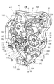
図8に示すように、オープンリンク19をアンロック位置からロック位置に切り替えるためのアクティブレバー25(本発明の「ロックレバー」に相当する)は、支持ケース110のうちオープンリンク19を挟んでインサイドオープンレバー回動軸20Jの反対側位置に配置されたアクティブレバー回動軸部53(本発明の「円筒軸支突部」に相当する)を中心に回動する。図13に示すように、アクティブレバー回動軸部53は、支持ケース110を構成する第1ケース分割体50に一体成形され、そのベース主板壁51から第2ケース分割体60のベース主板壁61に向かって起立している。アクティブレバー回動軸部53は、その芯部に先端開放の軸心孔53Hを有した円筒形状をなしている。
アクティブレバー25は、図13に示すように、アクティブレバー回動軸部53の外側に係合可能な回動中心孔25H1をその芯部に有する円筒部25Hと、円筒部25Hの外周面から上方に張り出した第1扇形突片25Aと、円筒部25Hの外周面から斜め左下方に張り出した扇形の第2扇形突片25Dと、円筒部25Hの外周面から斜め右側に突出したアクティブ作用アーム25Cとを備えている(図8参照)。
図9に示すように、第2扇形突片25Dの裏面(ベース主板壁51との対向面)からは、アクティブレバー回動軸部53と平行な方向に円柱状の節度ピン25Pが突出している。また、ベース主板壁51のうち、第2扇形突片25Dとの対向面には、節度バネ27(本発明の「弾性部材」に相当する)が取り付けられている。節度バネ27は、バネ線材の中間部をコイル状に巻回すると共に両端部を対向させかつ、それら対向部分の先端寄り位置を互いに接近させる側に山形状に屈曲させて1対の摺接突部27A,27Aを備えた構造になっている。そして、アクティブレバー25の節度ピン25Pが1対の摺接突部27A,27Aの間に挿通されており、アクティブレバー25が図10に示したロック位置と、図11に示したアンロック位置との間を回動する際に、節度ピン25Pが、1対の摺接突部27A,27Aの間を押し広げながら通過することで、アクティブレバー25が、ロック位置かアンロック位置の何れかに付勢されて、それらの中間領域で留まらないようになっている。
即ち、節度バネ27は、アクティブレバー25を、ロック位置とアンロック位置との中間位置から遠ざけるように付勢しており、節度ピン25Pが中間位置(1対の摺接突部27A,27Aの頂部の間)をロック位置側に乗り越えると、アクティブレバー25はロック位置側に向けて付勢され、節度ピン25Pが中間位置をアンロック位置側に乗り越えると、アクティブレバー25はアンロック位置側に向けて付勢される。
また、後述するが、アクティブレバー25は、支持ケース110に設けられた筒形ストッパ突部64(本発明の「ストッパ部」に相当する)と当接することで、ロック位置とアンロック位置とに位置決めされ(図10及び図11参照)、それらロック位置及びアンロック位置では、節度バネ27の付勢力によって筒形ストッパ突部64に押し付けられている。これにより、アクティブレバー25の回動方向におけるガタつきが無くされ、ロック位置とアンロック位置との2位置でのみ停止可能となっている。
図6Aから図7Bに示すように、アクティブ作用アーム25Cの先端部は、オープンリンク19におけるロック解除片19Bに下方から対向している。そして、図11から図10への変化に示すように、アクティブレバー25がアンロック位置からロック位置に回動するときに、アクティブ作用アーム25Cがロック解除片19Bを押し上げてオープンリンク19をアンロック位置からロック位置に移動する。
図8に示すように、第1扇形突片25Aのうちアクティブ作用アーム25Cに近い側の一側縁部からは、ロック維持アーム25Bが突出している。ロック維持アーム25Bの一部は、オープンリンク19の規制受部19Eに対して対向していて、ロック維持アーム25Bの先端部からは、規制受部19E側に向かってロック維持突部25T(図7A,図9参照)が突出している。そして、アクティブレバー25がアンロック位置に配置されると、ロック維持突部25Tが規制受部19Eの前方からずれ、アクティブレバー25がロック位置に配置されると、図7Aに示すように、ロック維持突部25Tが規制受部19Eに前方から突き合わされる。これにより、アクティブレバー25がロック位置に配置されたときには、インサイドオープンレバー20又はアウトサイドオープンレバー17によってオープンリンク19が押し上げられて、オープンリンク19のロック解除片19Bがアクティブ作用アーム25Cから離間してもロック維持突部25Tによってオープンリンク19がロック状態に保持される。
図8に示すように、第2扇形突片25Dの下端部からはケーブル結合片25Eが張り出している。そのケーブル結合片25Eには、ケーブルW2(図1参照)を介してドア101の内面に備えたロック操作部106(図2B参照)が接続されている。そして、ロック操作部106を操作することで、アクティブレバー25をアンロック位置とロック位置とに切り替えることができる。なお、ケーブルW2も、上記したケーブルW1と同様な構成(例えば、コントロールケーブル)である。
アクティブレバー25は、ドア101の内面のロック操作部106以外にも車内の集中ロックスイッチ107(図2B参照)や無線キー108(図2A参照)によってアンロック位置とロック位置とに切り替えることができる。そのために、モータ22、コネクタ22C、バスバー回路22B等の電機部品が支持ケース110に取り付けられている。図8に示すように、モータ22は、支持ケース110のうちアクティブレバー25の上方に配置され、モータ22の回転出力軸は第2外面11Bと平行になって斜め下方に突出し、その回転出力軸にウォームギヤ23が固定されている。
ウォームギヤ23に噛合するウォームホイール24は、ホイール回転軸部54を中心に回転し、そのホイール回転軸部54は、支持ケース110のうち、アクティブレバー回動軸部53より上方に配置されている。図13に示すように、ホイール回転軸部54は、支持ケース110を構成する第1ケース分割体50に一体成形され、ベース主板壁51から第2ケース分割体60のベース主板壁61に向かって起立している。ホイール回転軸部54は、芯部に螺子孔54Aを有した円柱状をなしている。そして、ホイール回転軸部54のうちベース主板壁51に近い基端側にウォームホイール24が回転可能に嵌合している。
図8に示すように、ウォームホイール24の一部は、ベース主板壁51と第1扇形突片25Aとの間に位置しており、第1扇形突片25Aに貫通形成された円弧孔25Sに、ウォームホイール24を貫通したホイール回転軸部54の先端部が突入している。円弧孔25Sは、アクティブレバー回動軸部53を中心とした円弧状に延びている。
図10及び図11に示すように、ウォームホイール24のうち第1扇形突片25Aとの対向面には、ホイール回転軸部54を間に挟んだ2位置に1対の回転押圧突部24A,24Aが突出形成されている。これに対し、第1扇形突片25Aのうち円弧孔25Sよりアクティブレバー回動軸部53から離れた側は、ウォームホイール24側に向かって厚肉になっていて、その厚肉部分における周方向の中央に係合溝25Mが形成されている。そして、ウォームホイール24は、通常は、回転押圧突部24A,24Aが円弧孔25Sの周方向に沿って並んだ位置に保持されていて、集中ロックスイッチ107や無線キー108をロック操作すると、ウォームホイール24が図11における反時計回り方向に180度回転する。すると、そのウォームホイール24の回転中に一方の回転押圧突部24Aが係合溝25Mに進入してから係合溝25Mにおける左側の溝内面25Nを押圧し、アクティブレバー25が反時計回り方向に回動して、図11に示したアンロック位置から図10に示したロック位置に切り替わる。
一方、集中ロックスイッチ107や無線キー108をアンロック操作すると、ウォームホイール24が図10における時計回り方向に180度回転する。すると、ウォームホイール24の回転中に一方の回転押圧突部24Aが係合溝25Mに進入してから係合溝25Mにおける右側の溝内面25Lを押圧し、アクティブレバー25が時計回り方向に回動して、図10に示したロック位置から図11に示したアンロック位置に切り替わる。
図8に示すように、第1扇形突片25Aから上方に向かって、検知アーム25Fが突出している。ベース主板壁51のうち、検知アーム25Fの回動領域の上方に検出スイッチ26が取り付けられ、その検出スイッチ26に備えた作動部が検知アーム25Fの回動領域内に突出している。検出スイッチ26の信号を車両100が取得して、アクティブレバー25がアンロック位置とロック位置の何れかに位置しているかを認識することができる。
なお、アクティブレバー25は、ドア101の内面に備えたロック操作部106だけでなく、外面に備えたキーシリンダ102にキー103(図2A参照)を挿入して操作することによってもアンロック位置とロック位置とに切り替えることができる。詳細な説明は省略するが、キーシリンダ102から入力した力は、キー操作伝達リンク30(図8及び図9参照)を介してアクティブレバー25に伝達される。
図13に示すように、支持ケース110を構成する第2ケース分割体60のベース主板壁61のうち、アクティブレバー回動軸部53の先端部が突き合わされた部分からは、ベース主板壁51に向かって軸心支柱63が起立している。軸心支柱63は、アクティブレバー回動軸部53と同軸に延びかつ、アクティブレバー回動軸部53の軸心孔53Hに嵌合している。これにより、アクティブレバー回動軸部53がその軸方向の両端で第1ケース分割体50と第2ケース分割体60により支持された構造となり、アクティブレバー回動軸部53の剛性が確保されている。また、軸心支柱63は先細り形状をなしており、軸心孔53Hの開口縁には、すり鉢状のガイドテーパ面53Gが形成されている。
第2ケース分割体60のベース主板壁61のうち、ホイール回転軸部54の先端部が突き合わされた部分からは、ベース主板壁51に向かって筒形ストッパ突部64が起立している。筒形ストッパ突部64は、ホイール回転軸部54と同軸の円筒形をなしている。また、筒形ストッパ突部64は、アクティブレバー25の円弧孔25Sに突入しており、その円弧孔25Sの内側で、第1ケース分割体50から起立したホイール回転軸部54の先端部の外側に嵌合している。これにより、ホイール回転軸部54及び筒形ストッパ突部64が、共に軸方向の両端部で第1ケース分割体50と第2ケース分割体60とにより支持された構造となっている。また、筒形ストッパ突部64の先端部は、ウォームホイール24の回転中心に備えた軸受筒24Bに軸方向から突き当てられており、ベース主板壁51との間でウォームホイール24の軸方向への移動を禁止している(図13参照)。なお、ホイール回転軸部54は、本発明の「ガイド支柱」に相当し、ウォームホイール24は、本発明の「連動回動部品」に相当する。
図16に示すように、筒形ストッパ突部64のうちホイール回転軸部54の先端部を受容した中心孔64Hは、第2ケース分割体60のベース主板壁61を貫通しており、そのベース主板壁61の外面(第2外面11B)側から中心孔64H内に挿入されたビス64Bが、ホイール回転軸部54の螺子孔54Aに締め付けられている。
また、筒形ストッパ突部64の外周面は、そのベース主板壁61に近い基端側では軸方向と平行な円筒外面64Aとなっており、先端側では軸方向に対して傾斜した円錐テーパ面64G1となっている。また、筒形ストッパ突部64が挿入された円弧孔25Sのうち、第2ケース分割体60側の開口縁全周に、内側に向かって下り傾斜した誘導傾斜面25Gが形成されている。
さらに、筒形ストッパ突部64における中心孔64Hの開口縁と、ホイール回転軸部54の先端外周縁にも、テーパ状の挿入ガイド面64G2、54Gが形成されている。
アクティブレバー25は、円弧孔25Sのうち、第2外面11Bに向かって右端の開口縁25Kが筒形ストッパ突部64の円筒外面64Aに当接することでロック位置に位置決めされ(図10参照)、円弧孔25Sのうち第2外面11Bに向かって左端の開口縁25Kが筒形ストッパ突部64の円筒外面64Aに当接することでアンロック位置に位置決めされる(図11参照)。
本実施形態のドアロック装置10の構成は以上である。このドアロック装置10は、第1ケース分割体50に、モータ22、ウォームホイール24、アクティブレバー25、節度バネ27等の各種部品を組み付けてから、第1ケース分割体50と第2ケース分割体60とを合体させて支持ケース110を完成させ、その支持ケース110にラッチモジュール120を組み付けることで完成する。
支持ケース110に組み付けられる部品のうち、モータ22、ウォームホイール24、節度バネ27、インサイドオープンレバー20、アウトサイドオープンレバー17については、組み付けの優先順位はなく、任意の順番で組み付けることができる。これに対し、アクティブレバー25は、図8及び図9に示すように、ウォームホイール24及び節度バネ27に重なる配置となっているので、ウォームホイール24及び節度バネ27を先に組み付けておいた状態で、アクティブレバー25をアクティブレバー回動軸部53に組み付けることになる。
アクティブレバー25を組み付けるときには、円弧孔25Sをホイール回転軸部54に重ねると共に、第2扇形突片25Dを節度バネ27に重ねて、節度ピン25Pを1対の摺接突部27A,27Aの間に挿入する。このとき、アクティブレバー25は、図14に示すように、ロック位置(図10参照)又はアンロック位置(図11参照)よりも、それらの中間位置から遠ざかった位置であって、節度バネ27の付勢力を受けない待機位置(節度ピン25Pが1対の摺接突部27A,27Aに押されていない位置)に組み付けることができる。
図14及び図15には、アクティブレバー25を、アンロック位置よりも中間位置から遠ざかった待機位置(「アンロック位置側の待機位置」という)にして、アクティブレバー回動軸部53に組み付けたときの状態が示されている。同図に示すように、アンロック位置側の待機位置では、アクティブレバー25の円弧孔25Sのうち第2外面11Bに向かって左側の端部が、ホイール回転軸部54の側面に当接するか又は近接配置される。また、図14に示すように、節度ピン25Pは、節度バネ27における1対の摺接突部27A,27Aの頂部よりもコイル部側に遊嵌されている。そして、ホイール回転軸部54と節度バネ27とが協働してアクティブレバー25の回動を規制しており、アクティブレバー25はアンロック位置側の待機位置に保持される。なお、ホイール回転軸部54は、本発明の「待機位置保持部」に相当する。
上記の如くアクティブレバー25を、「アンロック位置側の待機位置」に組み付けることができるのは、アクティブレバー25の回動領域をロック位置とアンロック位置との間に制限する筒形ストッパ突部64が、第2ケース分割体60に設けられており、第1ケース分割体50にアクティブレバー25を組み付ける時点では、筒形ストッパ突部64による取り付け位置の制限を受けないからである。従って、アクティブレバー回動軸部53にアクティブレバー25を組み付ける際に、節度バネ27の付勢力に抗して組み付ける(詳細には、節度ピン25Pをその軸方向から節度バネ27の1対の摺接突部27A,27Aの間に割り込ませる)必要はなく、容易にアクティブレバー25を組み付けることができる。
なお、以下の説明では、図14及び図15に示すように、アクティブレバー25をアンロック位置側の待機位置にして組み付けた場合を例示して説明を行うが、アクティブレバー25をロック位置よりも中間位置から遠ざかった待機位置にして組み付けた場合も同様である。
アクティブレバー25等の第1ケース分割体50に組み付けるべき部品を全て組み付けたら、第1ケース分割体50に第2ケース分割体60を被せて、これらをアクティブレバー25の回転軸方向で合体させる。具体的には、アクティブレバー回動軸部53と軸心支柱63及びホイール回転軸部54と筒形ストッパ突部64をそれぞれ目視で位置を合わせ、第1ケース分割体50に対して第2ケース分割体60を接近させていく。すると、まず、第2ケース分割体60から突出した軸心支柱63が、アクティブレバー回動軸部53の軸心孔53Hに突入する(図16参照)。軸心支柱63は先細り形状をなしており、軸心孔53Hの開口縁には、すり鉢状のガイドテーパ面53Gが形成されているから、軸心支柱63とアクティブレバー回動軸部53との嵌合をスムーズに開始することができる。
第2ケース分割体60を第1ケース分割体50にさらに接近させると、第2ケース分割体60から突出した筒形ストッパ突部64が、アクティブレバー25の円弧孔25Sに対して突入を開始すると共に、アクティブレバー25の円弧孔25Sに第1ベース分割体50側から突入しているホイール回転軸部54の先端部が、筒形ストッパ突部64の内側に突入を開始する(図17参照)。そして、筒形ストッパ突部64の円錐テーパ面64G1と、アクティブレバー25の円弧孔25Sの開口縁25Kとが、合体方向(アクティブレバー25の回転軸方向)で対向する。なお、円弧孔25Sの開口縁25Kは、本発明の「ストッパ当接部」に相当する。
さらに第2ケース分割体60を第1ケース分割体50に接近させると、筒形ストッパ突部64の円錐テーパ面64G1が、円弧孔25Sの開口縁25Kに摺接して、アクティブレバー25を待機位置から強制的に回動させる。詳細には、図15から図12又は図14から図11への変化に示すように、筒形ストッパ突部64の円錐テーパ面64G1が、円弧孔25Sのうち第2外面11Bに向かって左端の誘導傾斜面25Gと摺接して、円弧孔25Sとホイール回転軸部54との間に割り込む(図12参照)。このとき、アクティブレバー25が、待機位置から筒形ストッパ突部64の筒壁の厚さ分だけ回動してロック位置又はアンロック位置に配置される。なお、円錐テーパ面64G1及び誘導傾斜面25Gは、本発明の「ストッパガイド」に相当する。
図14から図11への変化に示すように、アクティブレバー25が待機位置からロック位置へと回動するとき、アクティブレバー25に備えた節度ピン25Pが、その軸方向と直交した方向で節度バネ27の1対の摺接突部27A,27Aの間に割り込む。すると、アクティブレバー25をロック位置とアンロック位置との中間位置から遠ざけるように付勢力が付与される。
上記したように、筒形ストッパ突部64がアクティブレバー25の円弧孔25Sの開口縁25Kと摺接してアクティブレバー25が待機位置から回動し、節度バネ27から付勢力を受け始めるよりも前に、アクティブレバー回動軸部53と軸心支柱63及び、ホイール回転軸部54と筒形ストッパ突部64とがそれぞれ合体方向でスライド係合しているから(図17参照)、第1ケース分割体50と第2ケース分割体60の合体過程で、アクティブレバー25が節度バネ27の付勢力を受けるようになっても、第1ケース分割体50と第2ケース分割体60が横ずれすることはない。よって、第1ケース分割体50と第2ケース分割体60の合体作業をスムーズに行うことができる。なお、合体方向で凹凸嵌合するホイール回転軸部54と筒形ストッパ突部64及び、軸心支柱63とアクティブレバー回動軸部53は、それぞれ本発明に係る「合体ガイド」に相当する。
また、円錐テーパ面64G1のみならず、円弧孔25Sの開口縁25Kにも誘導傾斜面25Gが設けられ、第1ケース分割体50と第2ケース分割体60との合体過程で筒形ストッパ突部64の円錐テーパ面64G1を誘導傾斜面25Gに摺接させることができるから、アクティブレバー25をよりスムーズに待機位置から回動させることができる。
さらに、本実施形態では、図11に示すように、アクティブレバー回動軸部53と筒形ストッパ突部64との軸間距離が、アクティブレバー回動軸部53と節度ピン25Pとの軸間距離よりも大きくなっている。即ち、「作用点」である節度ピン25Pから「支点」であるアクティブレバー回動軸部53までの距離に比べて、「支点」であるアクティブレバー回動軸部53から「力点」である筒形ストッパ突部64までの距離の方が長くなっているから、第2ケース分割体60によってアクティブレバー25を節度バネ27の付勢力に抗して待機位置から回動させる際に、より軽い力で回動させることができる。もちろん、アクティブレバー回動軸部53と筒形ストッパ突部64との軸間距離は、アクティブレバー回動軸部53と節度ピン25Pとの軸間距離より小さくなっていてもよい。
このように、本実施形態によれば、第1ケース分割体50にアクティブレバー25を組み付けるとき、アクティブレバー25は、節度バネ27から付勢力を受けない待機位置に組み付けられ、節度バネ27とホイール回転軸部54とによってその待機位置に保持される。また、第1ケース分割体50と第2ケース分割体60との合体過程では、それらに設けられたホイール回転軸部54と筒形ストッパ突部64及び、軸心支柱63とアクティブレバー回動軸部53の係合によって、第1ケース分割体50と第2ケース分割体60との横ずれが規制され、待機位置に保持されたアクティブレバー25の円弧孔25Sの開口縁25Kと第2ケース分割体60に備えた筒形ストッパ突部64とが、アクティブレバー25の回動軸方向で対向した状態で維持される。そして、第1ケース分割体50と第2ケース分割体60との合体過程で、筒形ストッパ突部64に設けられた円錐テーパ面64G1が、円弧孔25Sの開口縁25Kに摺接してアクティブレバー25を節度バネ27に押し付ける側に回動させる。つまり、第1ケース分割体50に対して待機位置で保持されていたアクティブレバー25が、第1ケース分割体50と第2ケース分割体60との合体過程で待機位置からロック位置又はアンロック位置へと移動する。
つまり、アクティブレバー25が第1ケース分割体50に支持されるのに対して、筒形ストッパ突部64が第2ケース分割体60に設けられており、アクティブレバー25を第1ケース分割体50に組み付けるときに、アクティブレバー25は節度バネ27から付勢力を受けない待機位置に組み付けることができるから、従来のように弾性部材の付勢力に抗してアクティブレバー25を組み付ける必要がなくなり、アクティブレバー25の組み付け作業性が向上する。
また、第1ケース分割体50と第2ケース分割体60とを合体させる過程で、筒形ストッパ突部64がアクティブレバー25を待機位置からロック位置又はアンロック位置へと回動させて、節度バネ27の付勢力を受けるようになるが、その付勢力を受け始めるよりも前に、ホイール回転軸部54と筒形ストッパ突部64及び、軸心支柱63とアクティブレバー回動軸部53とが係合して、第1ケース分割体50と第2ケース分割体60との横ずれを防止するから合体作業をスムーズに行うことができる。
また、アクティブレバー25が待機位置からロック位置又はアンロック位置へと回動するとき、節度ピン25Pは、その軸方向と直交した方向から1対の摺接突部27A,27Aの間に割り込んでいくので、節度ピン25Pをその軸方向から1対の摺接突部27A,27Aの間に割り込ませる場合と比べて、スムーズに1対の摺接突部27A,27Aの間に割り込ませることができる。
[他の実施形態]
本発明は、前記実施形態に限定されるものではなく、例えば、以下に説明するような実施形態も本発明の技術的範囲に含まれ、さらに、下記以外にも要旨を逸脱しない範囲内で種々変更して実施することができる。
本発明は、前記実施形態に限定されるものではなく、例えば、以下に説明するような実施形態も本発明の技術的範囲に含まれ、さらに、下記以外にも要旨を逸脱しない範囲内で種々変更して実施することができる。
(1)上記実施形態において、本発明の「ストッパ部」に相当する筒形ストッパ突部64は、アクティブレバー25に貫通形成された円弧孔25Sに突入してその開口縁25Kに摺接する構成であったが、「ストッパ部」は、このような構成に限定するものではなく、待機位置に位置するアクティブレバー25のどこか一部に摺接してロック位置又はアンロック位置に向けて回動させることが可能であればよい。上記実施形態のアクティブレバー25であれば、例えば、「ストッパ当接部」としての第2扇形突片25Dや検知アーム25Fの外側面に干渉するように「ストッパ部」を設けてもよい。
(2)上記実施形態では、本発明に係る「ストッパガイド」として、筒形ストッパ突部64の先端に円錐テーパ面64G1を設け、アクティブレバー25の円弧孔25Sに誘導傾斜面25Gを設けていたが、これらの何れか一方のみで「ストッパガイド」を構成してもよい。
(3)また、上記実施形態では、筒形ストッパ突部64の中心孔64Hの開口縁に挿入ガイド面64G2を設け、ホイール回転54の先端に挿入ガイド面54Gを設けていたが、これらの何れか一方のみを設けた構成としてもよい。
(4)上記実施形態では、本発明に係る「合体ガイド」として、アクティブレバー回動軸部53と軸心支柱63及び、ホイール回転軸部54と筒形ストッパ突部64を備えていたが、これら以外の例えば、第1ケース分割体50と第2ケース分割体60を螺子止めするための支柱とその支柱を受容する凹部を、「合体ガイド」として備えていてもよい。
(5)上記実施形態では、ドアロック装置10にモータ22及びウォームホイール24が備えられていたが、これらは必須ではなく、モータ及びウォームホイールを備えていない構成としてもよい。
10 ドアロック装置
24 ウォームホイール(連動回動部品)
25 アクティブレバー(ロックレバー)
25G 誘導傾斜面(ストッパガイド)
25H1 回動中心孔
25K 開口縁(ストッパ当接部)
25S 円弧孔
27 節度バネ(弾性部材)
50 第1ケース分割体
53 アクティブレバー回動軸部(円筒軸支突部)
54 ホイール回転軸部(ガイド支柱、待機位置保持部)
60 第2ケース分割体
63 軸心支柱
64 筒形ストッパ突部(ストッパ部)
64G1 円錐テーパ面(ストッパガイド)
100 車両
101 ドア
110 支持ケース
24 ウォームホイール(連動回動部品)
25 アクティブレバー(ロックレバー)
25G 誘導傾斜面(ストッパガイド)
25H1 回動中心孔
25K 開口縁(ストッパ当接部)
25S 円弧孔
27 節度バネ(弾性部材)
50 第1ケース分割体
53 アクティブレバー回動軸部(円筒軸支突部)
54 ホイール回転軸部(ガイド支柱、待機位置保持部)
60 第2ケース分割体
63 軸心支柱
64 筒形ストッパ突部(ストッパ部)
64G1 円錐テーパ面(ストッパガイド)
100 車両
101 ドア
110 支持ケース
Claims (5)
- 車両のドアに固定されるよう適合される支持ケースと、
前記支持ケース内に配置され、ロック位置とアンロック位置との間を回動して前記ドアをロック及びアンロックするよう適合されるロックレバーと、
前記支持ケースに設けられたストッパ部と、
前記ロックレバーに設けられたストッパ当接部と、
前記ロックレバーを前記ロック位置と前記アンロック位置との中間位置から遠ざけるように付勢し、その付勢力によって、前記ロックレバーの前記ストッパ当接部を前記支持ケースの前記ストッパ部に前記ロック位置又は前記アンロック位置で押し付ける弾性部材と、を備え、
前記支持ケースは、前記ロックレバーを回動可能に支持しかつ前記弾性部材を弾性変形可能に支持した第1ケース分割体と、前記ストッパ部を有した第2ケース分割体とを、前記ロックレバーの回動軸方向で合体することにより構成され、
前記第1ケース分割体に設けられ、前記第1ケース分割体と前記第2ケース分割体が分離した状態で、前記弾性部材と協働して前記ロックレバーの回動を規制し、前記ロックレバーが前記弾性部材から付勢力を受けずかつ前記ストッパ当接部が前記回動軸方向で前記ストッパ部と対向する待機位置に前記ロックレバーを保持する待機位置保持部と、
前記第1ケース分割体と前記第2ケース分割体とに設けられ、合体過程の前記第1ケース分割体と前記第2ケース分割体との横ずれを規制するように互いに係合して、前記ストッパ当接部と前記ストッパ部とが前記回動軸方向で対向した状態に維持する合体ガイドと、
前記ストッパ部及び前記ストッパ当接部の何れか一方に設けられて、前記第1ケース分割体及び前記第2ケース分割体の合体過程で他方に摺接して前記ロックレバーを前記弾性部材に押し付ける側に回動させて前記待機位置から前記ロック位置又は前記アンロック位置に移動するストッパガイドとを備えた、ドアロック装置。 - 前記ストッパ部及び前記ストッパ当接部の何れか一方に設けられた前記ストッパガイドが他方に摺接する前に、前記合体ガイドが互いに係合する、請求項1に記載のドアロック装置。
- 前記ロックレバーの回動中心を中心とした円弧孔を前記ロックレバーに貫通形成して、その円弧孔の一端部の開口縁を前記ストッパ当接部とし、
前記第2ケース分割体から突出して前記円弧孔の内部に突入した筒形ストッパ突部を設けて前記ストッパ部とすると共に、その筒形ストッパ突部の先端部にテーパ面を形成して前記ストッパガイドとし、
さらに、前記第1ケース分割体から突出して前記合体過程で前記筒形ストッパ突部の内側にスライド係合するガイド支柱を設けて、そのガイド支柱と前記筒形ストッパ突部とを前記合体ガイドとした、請求項1又は2に記載のドアロック装置。 - 前記ロックレバーの回動中心に貫通形成された回動中心孔と、
前記第1ケース分割体から突出して前記回動中心孔に挿入され、前記ロックレバーを回動可能に支持する円筒軸支突部と、
前記第2ケース分割体から突出して前記合体過程で前記円筒軸支突部の内側にスライド係合する軸心支柱とを設けた、請求項3に記載のドアロック装置。 - 前記ガイド支柱の基端部で、前記ロックレバーに連動して回動する連動回動部品を回動可能に軸支した、請求項3又は4に記載のドアロック装置。
Priority Applications (1)
| Application Number | Priority Date | Filing Date | Title |
|---|---|---|---|
| CN201290000943.9U CN203961528U (zh) | 2011-11-01 | 2012-10-26 | 门锁装置 |
Applications Claiming Priority (2)
| Application Number | Priority Date | Filing Date | Title |
|---|---|---|---|
| JP2011-240137 | 2011-11-01 | ||
| JP2011240137A JP5546521B2 (ja) | 2011-11-01 | 2011-11-01 | ドアロック装置 |
Publications (1)
| Publication Number | Publication Date |
|---|---|
| WO2013065593A1 true WO2013065593A1 (ja) | 2013-05-10 |
Family
ID=48191942
Family Applications (1)
| Application Number | Title | Priority Date | Filing Date |
|---|---|---|---|
| PCT/JP2012/077713 Ceased WO2013065593A1 (ja) | 2011-11-01 | 2012-10-26 | ドアロック装置 |
Country Status (3)
| Country | Link |
|---|---|
| JP (1) | JP5546521B2 (ja) |
| CN (1) | CN203961528U (ja) |
| WO (1) | WO2013065593A1 (ja) |
Cited By (1)
| Publication number | Priority date | Publication date | Assignee | Title |
|---|---|---|---|---|
| JP2013113008A (ja) * | 2011-11-29 | 2013-06-10 | Yuhshin Co Ltd | ドアロック装置 |
Families Citing this family (14)
| Publication number | Priority date | Publication date | Assignee | Title |
|---|---|---|---|---|
| JP6022237B2 (ja) * | 2012-06-29 | 2016-11-09 | 株式会社ユーシン | ドアロック装置 |
| EP3141680B1 (en) * | 2015-09-09 | 2018-01-31 | U-Shin Italia S.p.A. | Electronic handle for a vehicle door |
| CN107620529B (zh) | 2016-07-15 | 2020-12-15 | 株式会社安成 | 车辆用门锁装置 |
| JP6652709B2 (ja) * | 2016-07-15 | 2020-02-26 | 株式会社アンセイ | 車両用ドアロック装置 |
| JP6627672B2 (ja) | 2016-07-20 | 2020-01-08 | 株式会社アンセイ | 車両用ドアロック装置 |
| JP6627729B2 (ja) | 2016-11-25 | 2020-01-08 | 株式会社アンセイ | 車両用ドアロック装置 |
| JP6825979B2 (ja) * | 2017-04-29 | 2021-02-03 | 三井金属アクト株式会社 | 車両ドアラッチ装置 |
| CN107476684B (zh) * | 2017-10-09 | 2022-07-19 | 烟台三环锁业集团股份有限公司 | 一种汽车锁锁闭机构 |
| JP6627920B2 (ja) | 2018-06-26 | 2020-01-08 | 株式会社アンセイ | 車両用ドアロック装置 |
| CN110965868B (zh) * | 2018-09-28 | 2022-11-11 | 开开特股份公司 | 汽车锁 |
| JP7095644B2 (ja) * | 2019-04-02 | 2022-07-05 | 三井金属アクト株式会社 | ドアラッチ装置 |
| CN110428560B (zh) * | 2019-07-31 | 2021-05-14 | 深圳市易联达商用设备有限公司 | 一种基于扫描平台的pos收银终端 |
| JP6941246B1 (ja) * | 2021-02-15 | 2021-09-29 | 株式会社神菱 | ドアハンドル |
| JP7827980B2 (ja) | 2022-06-06 | 2026-03-11 | 株式会社アンセイ | 車両用開閉体のロック装置 |
Citations (4)
| Publication number | Priority date | Publication date | Assignee | Title |
|---|---|---|---|---|
| JP2006266026A (ja) * | 2005-03-25 | 2006-10-05 | Aisin Seiki Co Ltd | 車両用ドアロック装置 |
| JP2007138537A (ja) * | 2005-11-17 | 2007-06-07 | Aisin Seiki Co Ltd | 自動車用ドアロック装置 |
| WO2011118356A1 (ja) * | 2010-03-24 | 2011-09-29 | アイシン精機株式会社 | 車両用ドアロック装置 |
| WO2011132474A1 (ja) * | 2010-04-22 | 2011-10-27 | アイシン精機株式会社 | 車両用ドアロック装置 |
-
2011
- 2011-11-01 JP JP2011240137A patent/JP5546521B2/ja not_active Expired - Fee Related
-
2012
- 2012-10-26 CN CN201290000943.9U patent/CN203961528U/zh not_active Expired - Fee Related
- 2012-10-26 WO PCT/JP2012/077713 patent/WO2013065593A1/ja not_active Ceased
Patent Citations (4)
| Publication number | Priority date | Publication date | Assignee | Title |
|---|---|---|---|---|
| JP2006266026A (ja) * | 2005-03-25 | 2006-10-05 | Aisin Seiki Co Ltd | 車両用ドアロック装置 |
| JP2007138537A (ja) * | 2005-11-17 | 2007-06-07 | Aisin Seiki Co Ltd | 自動車用ドアロック装置 |
| WO2011118356A1 (ja) * | 2010-03-24 | 2011-09-29 | アイシン精機株式会社 | 車両用ドアロック装置 |
| WO2011132474A1 (ja) * | 2010-04-22 | 2011-10-27 | アイシン精機株式会社 | 車両用ドアロック装置 |
Cited By (1)
| Publication number | Priority date | Publication date | Assignee | Title |
|---|---|---|---|---|
| JP2013113008A (ja) * | 2011-11-29 | 2013-06-10 | Yuhshin Co Ltd | ドアロック装置 |
Also Published As
| Publication number | Publication date |
|---|---|
| JP5546521B2 (ja) | 2014-07-09 |
| JP2013096144A (ja) | 2013-05-20 |
| CN203961528U (zh) | 2014-11-26 |
Similar Documents
| Publication | Publication Date | Title |
|---|---|---|
| JP5546521B2 (ja) | ドアロック装置 | |
| JP4267933B2 (ja) | 車両用ドアロック装置 | |
| JP4755528B2 (ja) | 車両用ドアラッチのリモートコントロール装置 | |
| US8939511B2 (en) | Lock mechanism for automobile rear seat | |
| US10352069B2 (en) | Locking lever and vehicle door opening-closing device | |
| KR20120096938A (ko) | 차량용 도어 래치 장치에서의 액추에이터 | |
| JP2011052497A (ja) | 自動車用ドアのインサイドハンドル装置 | |
| US20180112442A1 (en) | Door lock apparatus | |
| JP5309408B2 (ja) | 車両用ドアラッチ装置 | |
| JP2016089349A (ja) | 車両用ドアラッチ装置および車両用ドアラッチ装置の組立方法 | |
| JP2011140811A (ja) | ドアラッチアクチュエータ | |
| JP5005047B2 (ja) | 車両用ドアラッチ装置 | |
| WO2013137040A1 (ja) | 嵌合構造 | |
| JP2015137509A (ja) | 車両用ドアラッチ装置 | |
| JP5213190B2 (ja) | 車両用ドアラッチ装置 | |
| JP5808987B2 (ja) | 車両ドア操作中継セット及びスライドドアの製造方法 | |
| WO2016098158A1 (ja) | 開放制御装置 | |
| US20180245378A1 (en) | Door latch apparatus with childproof lock mechanism and assembling method of childproof lock mechanism | |
| JP5495166B2 (ja) | 車両用ドアラッチ装置 | |
| JP2021143483A (ja) | 車両用リッドロック装置及び車両用リッドロック装置の組立て方法 | |
| JP7067076B2 (ja) | ドアインサイドハンドル装置 | |
| JP4673797B2 (ja) | 車両用ドアロック装置 | |
| JP4700561B2 (ja) | 車両用ドアラッチのリモートコントロール装置 | |
| JP6078881B2 (ja) | 自動車用ドアラッチ装置 | |
| WO2016067480A1 (ja) | 車両用ドアラッチ装置 |
Legal Events
| Date | Code | Title | Description |
|---|---|---|---|
| WWE | Wipo information: entry into national phase |
Ref document number: 201290000943.9 Country of ref document: CN |
|
| 121 | Ep: the epo has been informed by wipo that ep was designated in this application |
Ref document number: 12846087 Country of ref document: EP Kind code of ref document: A1 |
|
| NENP | Non-entry into the national phase |
Ref country code: DE |
|
| 122 | Ep: pct application non-entry in european phase |
Ref document number: 12846087 Country of ref document: EP Kind code of ref document: A1 |