WO2013061746A1 - 吸着シート及びその製造方法とその利用 - Google Patents
吸着シート及びその製造方法とその利用 Download PDFInfo
- Publication number
- WO2013061746A1 WO2013061746A1 PCT/JP2012/075750 JP2012075750W WO2013061746A1 WO 2013061746 A1 WO2013061746 A1 WO 2013061746A1 JP 2012075750 W JP2012075750 W JP 2012075750W WO 2013061746 A1 WO2013061746 A1 WO 2013061746A1
- Authority
- WO
- WIPO (PCT)
- Prior art keywords
- adsorbent
- sheet
- adsorption
- layer
- vapor pressure
- Prior art date
- Legal status (The legal status is an assumption and is not a legal conclusion. Google has not performed a legal analysis and makes no representation as to the accuracy of the status listed.)
- Ceased
Links
Images


Classifications
-
- B—PERFORMING OPERATIONS; TRANSPORTING
- B01—PHYSICAL OR CHEMICAL PROCESSES OR APPARATUS IN GENERAL
- B01J—CHEMICAL OR PHYSICAL PROCESSES, e.g. CATALYSIS OR COLLOID CHEMISTRY; THEIR RELEVANT APPARATUS
- B01J20/00—Solid sorbent compositions or filter aid compositions; Sorbents for chromatography; Processes for preparing, regenerating or reactivating thereof
- B01J20/30—Processes for preparing, regenerating, or reactivating
-
- B—PERFORMING OPERATIONS; TRANSPORTING
- B01—PHYSICAL OR CHEMICAL PROCESSES OR APPARATUS IN GENERAL
- B01J—CHEMICAL OR PHYSICAL PROCESSES, e.g. CATALYSIS OR COLLOID CHEMISTRY; THEIR RELEVANT APPARATUS
- B01J20/00—Solid sorbent compositions or filter aid compositions; Sorbents for chromatography; Processes for preparing, regenerating or reactivating thereof
- B01J20/02—Solid sorbent compositions or filter aid compositions; Sorbents for chromatography; Processes for preparing, regenerating or reactivating thereof comprising inorganic material
- B01J20/06—Solid sorbent compositions or filter aid compositions; Sorbents for chromatography; Processes for preparing, regenerating or reactivating thereof comprising inorganic material comprising oxides or hydroxides of metals not provided for in group B01J20/04
- B01J20/08—Solid sorbent compositions or filter aid compositions; Sorbents for chromatography; Processes for preparing, regenerating or reactivating thereof comprising inorganic material comprising oxides or hydroxides of metals not provided for in group B01J20/04 comprising aluminium oxide or hydroxide; comprising bauxite
-
- B—PERFORMING OPERATIONS; TRANSPORTING
- B01—PHYSICAL OR CHEMICAL PROCESSES OR APPARATUS IN GENERAL
- B01J—CHEMICAL OR PHYSICAL PROCESSES, e.g. CATALYSIS OR COLLOID CHEMISTRY; THEIR RELEVANT APPARATUS
- B01J20/00—Solid sorbent compositions or filter aid compositions; Sorbents for chromatography; Processes for preparing, regenerating or reactivating thereof
- B01J20/02—Solid sorbent compositions or filter aid compositions; Sorbents for chromatography; Processes for preparing, regenerating or reactivating thereof comprising inorganic material
- B01J20/10—Solid sorbent compositions or filter aid compositions; Sorbents for chromatography; Processes for preparing, regenerating or reactivating thereof comprising inorganic material comprising silica or silicate
- B01J20/103—Solid sorbent compositions or filter aid compositions; Sorbents for chromatography; Processes for preparing, regenerating or reactivating thereof comprising inorganic material comprising silica or silicate comprising silica
-
- B—PERFORMING OPERATIONS; TRANSPORTING
- B01—PHYSICAL OR CHEMICAL PROCESSES OR APPARATUS IN GENERAL
- B01J—CHEMICAL OR PHYSICAL PROCESSES, e.g. CATALYSIS OR COLLOID CHEMISTRY; THEIR RELEVANT APPARATUS
- B01J20/00—Solid sorbent compositions or filter aid compositions; Sorbents for chromatography; Processes for preparing, regenerating or reactivating thereof
- B01J20/02—Solid sorbent compositions or filter aid compositions; Sorbents for chromatography; Processes for preparing, regenerating or reactivating thereof comprising inorganic material
- B01J20/10—Solid sorbent compositions or filter aid compositions; Sorbents for chromatography; Processes for preparing, regenerating or reactivating thereof comprising inorganic material comprising silica or silicate
- B01J20/16—Alumino-silicates
- B01J20/18—Synthetic zeolitic molecular sieves
-
- B—PERFORMING OPERATIONS; TRANSPORTING
- B01—PHYSICAL OR CHEMICAL PROCESSES OR APPARATUS IN GENERAL
- B01J—CHEMICAL OR PHYSICAL PROCESSES, e.g. CATALYSIS OR COLLOID CHEMISTRY; THEIR RELEVANT APPARATUS
- B01J20/00—Solid sorbent compositions or filter aid compositions; Sorbents for chromatography; Processes for preparing, regenerating or reactivating thereof
- B01J20/02—Solid sorbent compositions or filter aid compositions; Sorbents for chromatography; Processes for preparing, regenerating or reactivating thereof comprising inorganic material
- B01J20/20—Solid sorbent compositions or filter aid compositions; Sorbents for chromatography; Processes for preparing, regenerating or reactivating thereof comprising inorganic material comprising free carbon; comprising carbon obtained by carbonising processes
-
- B—PERFORMING OPERATIONS; TRANSPORTING
- B01—PHYSICAL OR CHEMICAL PROCESSES OR APPARATUS IN GENERAL
- B01J—CHEMICAL OR PHYSICAL PROCESSES, e.g. CATALYSIS OR COLLOID CHEMISTRY; THEIR RELEVANT APPARATUS
- B01J20/00—Solid sorbent compositions or filter aid compositions; Sorbents for chromatography; Processes for preparing, regenerating or reactivating thereof
- B01J20/28—Solid sorbent compositions or filter aid compositions; Sorbents for chromatography; Processes for preparing, regenerating or reactivating thereof characterised by their form or physical properties
- B01J20/28014—Solid sorbent compositions or filter aid compositions; Sorbents for chromatography; Processes for preparing, regenerating or reactivating thereof characterised by their form or physical properties characterised by their form
- B01J20/2803—Sorbents comprising a binder, e.g. for forming aggregated, agglomerated or granulated products
-
- B—PERFORMING OPERATIONS; TRANSPORTING
- B01—PHYSICAL OR CHEMICAL PROCESSES OR APPARATUS IN GENERAL
- B01J—CHEMICAL OR PHYSICAL PROCESSES, e.g. CATALYSIS OR COLLOID CHEMISTRY; THEIR RELEVANT APPARATUS
- B01J20/00—Solid sorbent compositions or filter aid compositions; Sorbents for chromatography; Processes for preparing, regenerating or reactivating thereof
- B01J20/28—Solid sorbent compositions or filter aid compositions; Sorbents for chromatography; Processes for preparing, regenerating or reactivating thereof characterised by their form or physical properties
- B01J20/28014—Solid sorbent compositions or filter aid compositions; Sorbents for chromatography; Processes for preparing, regenerating or reactivating thereof characterised by their form or physical properties characterised by their form
- B01J20/28033—Membrane, sheet, cloth, pad, lamellar or mat
- B01J20/28035—Membrane, sheet, cloth, pad, lamellar or mat with more than one layer, e.g. laminates, separated sheets
-
- B—PERFORMING OPERATIONS; TRANSPORTING
- B01—PHYSICAL OR CHEMICAL PROCESSES OR APPARATUS IN GENERAL
- B01J—CHEMICAL OR PHYSICAL PROCESSES, e.g. CATALYSIS OR COLLOID CHEMISTRY; THEIR RELEVANT APPARATUS
- B01J20/00—Solid sorbent compositions or filter aid compositions; Sorbents for chromatography; Processes for preparing, regenerating or reactivating thereof
- B01J20/28—Solid sorbent compositions or filter aid compositions; Sorbents for chromatography; Processes for preparing, regenerating or reactivating thereof characterised by their form or physical properties
- B01J20/28014—Solid sorbent compositions or filter aid compositions; Sorbents for chromatography; Processes for preparing, regenerating or reactivating thereof characterised by their form or physical properties characterised by their form
- B01J20/28033—Membrane, sheet, cloth, pad, lamellar or mat
- B01J20/2804—Sheets with a specific shape, e.g. corrugated, folded, pleated, helical
-
- B—PERFORMING OPERATIONS; TRANSPORTING
- B01—PHYSICAL OR CHEMICAL PROCESSES OR APPARATUS IN GENERAL
- B01J—CHEMICAL OR PHYSICAL PROCESSES, e.g. CATALYSIS OR COLLOID CHEMISTRY; THEIR RELEVANT APPARATUS
- B01J20/00—Solid sorbent compositions or filter aid compositions; Sorbents for chromatography; Processes for preparing, regenerating or reactivating thereof
- B01J20/30—Processes for preparing, regenerating, or reactivating
- B01J20/34—Regenerating or reactivating
- B01J20/3433—Regenerating or reactivating of sorbents or filter aids other than those covered by B01J20/3408 - B01J20/3425
-
- B—PERFORMING OPERATIONS; TRANSPORTING
- B01—PHYSICAL OR CHEMICAL PROCESSES OR APPARATUS IN GENERAL
- B01J—CHEMICAL OR PHYSICAL PROCESSES, e.g. CATALYSIS OR COLLOID CHEMISTRY; THEIR RELEVANT APPARATUS
- B01J20/00—Solid sorbent compositions or filter aid compositions; Sorbents for chromatography; Processes for preparing, regenerating or reactivating thereof
- B01J20/30—Processes for preparing, regenerating, or reactivating
- B01J20/34—Regenerating or reactivating
- B01J20/3491—Regenerating or reactivating by pressure treatment
-
- B—PERFORMING OPERATIONS; TRANSPORTING
- B01—PHYSICAL OR CHEMICAL PROCESSES OR APPARATUS IN GENERAL
- B01D—SEPARATION
- B01D2253/00—Adsorbents used in seperation treatment of gases and vapours
- B01D2253/10—Inorganic adsorbents
- B01D2253/102—Carbon
-
- B—PERFORMING OPERATIONS; TRANSPORTING
- B01—PHYSICAL OR CHEMICAL PROCESSES OR APPARATUS IN GENERAL
- B01D—SEPARATION
- B01D2253/00—Adsorbents used in seperation treatment of gases and vapours
- B01D2253/10—Inorganic adsorbents
- B01D2253/104—Alumina
-
- B—PERFORMING OPERATIONS; TRANSPORTING
- B01—PHYSICAL OR CHEMICAL PROCESSES OR APPARATUS IN GENERAL
- B01D—SEPARATION
- B01D2253/00—Adsorbents used in seperation treatment of gases and vapours
- B01D2253/10—Inorganic adsorbents
- B01D2253/106—Silica or silicates
-
- B—PERFORMING OPERATIONS; TRANSPORTING
- B01—PHYSICAL OR CHEMICAL PROCESSES OR APPARATUS IN GENERAL
- B01D—SEPARATION
- B01D2253/00—Adsorbents used in seperation treatment of gases and vapours
- B01D2253/10—Inorganic adsorbents
- B01D2253/106—Silica or silicates
- B01D2253/108—Zeolites
-
- B—PERFORMING OPERATIONS; TRANSPORTING
- B01—PHYSICAL OR CHEMICAL PROCESSES OR APPARATUS IN GENERAL
- B01D—SEPARATION
- B01D2253/00—Adsorbents used in seperation treatment of gases and vapours
- B01D2253/30—Physical properties of adsorbents
- B01D2253/302—Dimensions
- B01D2253/308—Pore size
-
- B—PERFORMING OPERATIONS; TRANSPORTING
- B01—PHYSICAL OR CHEMICAL PROCESSES OR APPARATUS IN GENERAL
- B01D—SEPARATION
- B01D2257/00—Components to be removed
- B01D2257/80—Water
-
- B—PERFORMING OPERATIONS; TRANSPORTING
- B01—PHYSICAL OR CHEMICAL PROCESSES OR APPARATUS IN GENERAL
- B01D—SEPARATION
- B01D2257/00—Components to be removed
- B01D2257/90—Odorous compounds not provided for in groups B01D2257/00 - B01D2257/708
-
- B—PERFORMING OPERATIONS; TRANSPORTING
- B01—PHYSICAL OR CHEMICAL PROCESSES OR APPARATUS IN GENERAL
- B01D—SEPARATION
- B01D2258/00—Sources of waste gases
- B01D2258/06—Polluted air
-
- B—PERFORMING OPERATIONS; TRANSPORTING
- B01—PHYSICAL OR CHEMICAL PROCESSES OR APPARATUS IN GENERAL
- B01D—SEPARATION
- B01D53/00—Separation of gases or vapours; Recovering vapours of volatile solvents from gases; Chemical or biological purification of waste gases, e.g. engine exhaust gases, smoke, fumes, flue gases, aerosols
- B01D53/02—Separation of gases or vapours; Recovering vapours of volatile solvents from gases; Chemical or biological purification of waste gases, e.g. engine exhaust gases, smoke, fumes, flue gases, aerosols by adsorption, e.g. preparative gas chromatography
-
- B—PERFORMING OPERATIONS; TRANSPORTING
- B01—PHYSICAL OR CHEMICAL PROCESSES OR APPARATUS IN GENERAL
- B01D—SEPARATION
- B01D53/00—Separation of gases or vapours; Recovering vapours of volatile solvents from gases; Chemical or biological purification of waste gases, e.g. engine exhaust gases, smoke, fumes, flue gases, aerosols
- B01D53/02—Separation of gases or vapours; Recovering vapours of volatile solvents from gases; Chemical or biological purification of waste gases, e.g. engine exhaust gases, smoke, fumes, flue gases, aerosols by adsorption, e.g. preparative gas chromatography
- B01D53/04—Separation of gases or vapours; Recovering vapours of volatile solvents from gases; Chemical or biological purification of waste gases, e.g. engine exhaust gases, smoke, fumes, flue gases, aerosols by adsorption, e.g. preparative gas chromatography with stationary adsorbents
- B01D53/0407—Constructional details of adsorbing systems
-
- B—PERFORMING OPERATIONS; TRANSPORTING
- B01—PHYSICAL OR CHEMICAL PROCESSES OR APPARATUS IN GENERAL
- B01D—SEPARATION
- B01D53/00—Separation of gases or vapours; Recovering vapours of volatile solvents from gases; Chemical or biological purification of waste gases, e.g. engine exhaust gases, smoke, fumes, flue gases, aerosols
- B01D53/02—Separation of gases or vapours; Recovering vapours of volatile solvents from gases; Chemical or biological purification of waste gases, e.g. engine exhaust gases, smoke, fumes, flue gases, aerosols by adsorption, e.g. preparative gas chromatography
- B01D53/06—Separation of gases or vapours; Recovering vapours of volatile solvents from gases; Chemical or biological purification of waste gases, e.g. engine exhaust gases, smoke, fumes, flue gases, aerosols by adsorption, e.g. preparative gas chromatography with moving adsorbents, e.g. rotating beds
-
- B—PERFORMING OPERATIONS; TRANSPORTING
- B01—PHYSICAL OR CHEMICAL PROCESSES OR APPARATUS IN GENERAL
- B01D—SEPARATION
- B01D53/00—Separation of gases or vapours; Recovering vapours of volatile solvents from gases; Chemical or biological purification of waste gases, e.g. engine exhaust gases, smoke, fumes, flue gases, aerosols
- B01D53/34—Chemical or biological purification of waste gases
- B01D53/46—Removing components of defined structure
- B01D53/72—Organic compounds not provided for in groups B01D53/48 - B01D53/70, e.g. hydrocarbons
Definitions
- the present invention provides an adsorbent sheet in which two or more adsorbent layers are provided on the same surface of a substrate by applying two or more adsorbent layer forming coating solutions in a stripe shape, and a method for producing the adsorbent sheet,
- the present invention relates to an adsorption element and a desiccant air conditioner using the adsorption sheet.
- Adsorbents such as zeolite, porous silica, activated alumina, and activated carbon are used for humidity conditioning, deodorization, gas separation and purification, adsorption heat pumps, and the like.
- a desiccant rotor in which various adsorbents are supported on a honeycomb rotor is used for a desiccant air conditioner.
- the desiccant air conditioner has a flow path for the air to be treated for bringing the air to be treated into contact with the adsorbing element and adsorbing the moisture in the air to be adsorbed to the adsorbing element, and the air for regeneration heated by the heat source And a regeneration air circulation path for regenerating by desorbing moisture in the adsorption element by contacting with the adsorption element, and the air to be treated and the regeneration air are alternately circulated through the adsorption element. It is a thing. In the desiccant air conditioner, continuous adsorption of moisture is performed by the adsorption element, and at the same time, moisture adsorbed on the adsorption element can be desorbed and regenerated. Therefore, it is more energy-saving than the cooling and dehumidifying method and has a high practical value as a technique capable of controlling the humidity of the air-conditioned space.
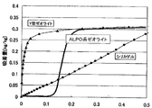
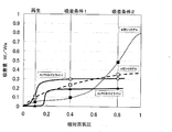
- FIG. 1 and 2 show changes in moisture absorption (water vapor adsorption isotherm) with respect to relative vapor pressures of various adsorbents.
- an adsorption element mainly composed of a Y-type zeolite is one of the typical rotors.
- the adsorption isotherm is almost linear in the dehumidifying operation range with a pressure of 0.4 (40% RH) or less, and has a large adsorption amount change at a relative vapor pressure of 0.05 (5% RH) or less.
- regeneration of the adsorption element must be performed at a low relative vapor pressure, that is, at a higher temperature (for example, 100 ° C. or higher).
- a zeolite having a so-called S-shaped adsorption characteristic such as the ALPO zeolite shown in FIGS. Examples thereof include those described in Patent Documents 2 to 5.
- ALPO-based zeolites it is possible to lower the regeneration temperature of the adsorption element as compared with silica gel and conventional Y-type zeolite, and therefore, utilization of a low-temperature heat source is expected.
- silica gel which is a conventional representative adsorbent, cannot be said to have a large change in the amount of saturated adsorption at a relative vapor pressure of 0.1 to 0.4.
- S-shaped adsorption equilibrium characteristics are exhibited on the low relative humidity (vapor pressure) side, and a large change is observed in the saturated adsorption amount in the relative vapor pressure range of 0.1 to 0.4.
- silica gel is more saturated than ALPO zeolite. Large change in adsorption amount. That is, the relative vapor pressure range in which adsorption and desorption can be performed is greatly different between zeolite mainly composed of micropores and silica gel mainly composed of mesopores.
- the adsorbents have different relative vapor pressure ranges that are advantageous for adsorption and desorption depending on the hydrophilicity and the pore diameter, it is possible to improve the dehumidifying efficiency of the desiccant rotor by effectively using different adsorbents. It is considered possible. That is, generally, the air to be treated that flows inside the adsorption element has a gradient in humidity and temperature from the inlet to the outlet of the adsorption element. Therefore, it can be expected that the dehumidifying performance of the adsorption element is improved by arranging an optimum adsorbent according to the conditions of the air to be treated and the air for regeneration in each place of the adsorption element.
- Patent Document 1 discloses the pore diameter of a silica-based porous body having a uniform nanopore diameter from the inlet side to the outlet side of the air to be treated. Adsorption elements arranged so as to be gradually or gradually reduced have been proposed.
- the adsorbing element exemplified in Patent Document 1 can adsorb / desorb more water vapor within a limited moisture absorption treatment-regeneration time of the desiccant rotor than an adsorbing element having a uniform pore diameter.
- a solution of a micelle-silicate complex is formed, dried, and fired to form an adsorbing element.
- an adsorption element is configured by applying an adsorbent for water vapor adsorption to a ventilation structure (aeration element) provided with a large number of ventilation holes such as a corrugated type, a honeycomb type, and a lattice type.
- a ventilation structure anation element
- the ventilation element coats two or more kinds of adsorbents in accordance with the ventilation direction.
- an element formed into a predetermined shape is described.
- An air-permeable element is manufactured by applying an adsorbent to the material.
- JP 2002-001106 A Japanese Patent Publication No. 1-57041 JP 2003-183020 A JP 2004-136269 A JP 2010-094609 A
- Patent Document 1 in order to form a silica-based porous body, the micelle-silicate complex solution needs to be fired at 600 ° C. or higher after being applied to the base material, and the base material can withstand the firing temperature. There was a problem that it was limited to ceramics. Further, the adsorbent is also limited to those that can be co-fired with the silicate, and it is difficult to apply the technique of Patent Document 1 to other adsorbents such as zeolite and activated carbon to further enhance the functionality. There was a problem that there was.
- the silica-based porous body that is the adsorbent layer is poor in flexibility, it has been difficult to fabricate a sheet made of the base material and the silica-based porous body and then process it into a honeycomb shape. For this reason, when obtaining a honeycomb-shaped element, it is necessary to apply a solution of a micellar silicate complex to a substrate processed into a honeycomb shape in advance by a method such as dipping. However, it is difficult to apply a different kind of adsorbent pattern onto a substrate having such a complicated shape, resulting in a problem of poor mass production and high cost.
- the concept of separately arranging different kinds of adsorbents in one adsorbing element and the method of manufacturing the adsorbing element by corrugating the adsorbing sheet coated with the adsorbent were known, Conventionally, the corrugating process has not been performed by using an adsorbent sheet coated in a stripe shape in advance as an original sheet.
- the reason for this is as follows. Regarding the specifications of the adsorption sheet, it is necessary to make a series of processes to obtain the adsorption element, and to make decisions based on the knowledge obtained after evaluating and examining the obtained adsorption element. In particular, it is difficult to design the layer structure of the adsorbing sheet, the material composition, the adsorbing characteristics of each adsorbent arrangement portion, and the arrangement pattern. In addition, when two or more adsorbents are applied to an element pre-shaped in a corrugated shape or the like, the application thickness is usually different because the adsorbent is applied separately for each adsorbent.
- the present invention is an adsorption sheet in which two or more types of adsorbent layers are provided in the form of stripes on the same surface of a substrate, satisfying all the required characteristics of adsorption performance, processing performance, and mass productivity, It is an object of the present invention to provide a specification and manufacturing method of an adsorption sheet that can be used as an original sheet for producing an adsorption element of the form, and an adsorption element and a desiccant air conditioner using the adsorption sheet.
- the arrangement pattern of the adsorbent of the adsorbing sheet is asymmetric with respect to a center line (referred to as MD center line) along the MD direction (vertical direction).
- MD center line a center line along the MD direction (vertical direction).
- the advantage of having two or more types of adsorbent layers as an adsorbed article can be obtained by the adsorption isotherm having a predetermined relationship between the right side and the left side of the center line.
- the arrangement pattern and adsorption characteristics are different between the right side and the left side of the center line, the difference in average thickness is within a predetermined range, so that there is no air leakage between cells, and a single-stage corrugated sheet or rotor-like element.
- the tension during winding can be made uniform in the width direction, and peeling between the corrugated liner can be prevented.
- peeling due to strain can be prevented.
- the inventors have also found an upper limit of the thickness of each adsorbent layer on the substrate in order to develop a certain bending resistance.
- the thickness of the adsorbent layer that can be bent without a defect by a cylindrical mandrel having a diameter of 10 mm was 300 ⁇ m or less.
- the present inventors used a knife coater, particularly a roll knife coater (comma coater: registered trademark of Hirano Techseed), and partitioned the liquid dam with a separator. It discovered that it could manufacture efficiently by apply
- the present invention has been achieved on the basis of such findings, and the gist thereof is as follows.
- the two or more types of adsorbent layers include an organic binder and an adsorbent, and the content of the organic binder in the adsorbent layer is 10% by weight or more.
- the two or more adsorbent layers are provided in stripes on the same surface of the substrate.
- the two or more types of adsorbent layers are provided asymmetrically with respect to the center line along the MD direction of the adsorbing sheet.
- the adsorption sheet has a change amount of the saturated adsorption amount when the relative vapor pressure is changed by 0.15 and the relative vapor pressure is in the range of 0.01 to 0.95 on the 25 ° C. water vapor adsorption isotherm. The range of the maximum relative vapor pressure differs by 0.05 or more on the right side and the left side of the center line.
- the adsorption sheet has an average thickness difference of 20 ⁇ m or less between the right side and the left side of the center line.
- the adsorbent layer has a thickness of 300 ⁇ m or less, and in a bending resistance test by a cylindrical mandrel method in accordance with JIS-K5600-5-1, no crack and peeling are observed at a mandrel diameter of 10 mm [1] Adsorption sheet as described in 1.
- the substrate is made of a thermoplastic resin or metal having a weight reduction rate of 1% by weight or less when heat-treated at 300 ° C. for 30 minutes in the air [1] to [1] 4].
- a knife coater comprising a portion that can divide a liquid dam of a knife coater with one or more separators and separately accommodate two or more adsorbent layer forming coating liquids each containing an adsorbent and an organic binder.
- An adsorbing element that uses the adsorbing sheet according to any one of [1] to [5] as an original sheet, and the relative vapor pressure is 0 between the right side and the left side of the center line. .15
- the relative vapor pressure range in which the amount of change is maximum flows from the high side to the low side to perform adsorption, and the regeneration medium is moved in a direction opposite to the flow direction of the fluid to be treated.
- An adsorbing element characterized by flowing and desorbing.
- An adsorbing element formed by laminating a plurality of corrugated adsorbing sheets according to any one of [1] to [5] into a honeycomb shape.
- the adsorbent sheet of the present invention is provided with two or more adsorbent layers using adsorbents having different average pore diameters on a substrate, and adsorbent layers having different average pore diameters of the adsorbents. By providing each in an appropriate arrangement, it is possible to improve the performance of the adsorption sheet and the adsorption element using the adsorption sheet.
- the adsorbent layer contains an organic binder, the adsorbent layer can be formed without performing high-temperature firing. Therefore, the material of the base material is not limited to a high heat resistant material, such as a thermoplastic resin. Can also be used.
- the two or more types of adsorbent layers are provided asymmetrically with respect to the center line of the adsorbing sheet along the MD direction, that is, the stripe extending direction, and the relative vapor pressure changes on the left and right of the center line. Since the relative humidity range in which the amount of change at the time is maximum differs by 0.05 or more, the relative humidity range in which adsorption and desorption can be efficiently performed on the left and right sides of the suction sheet is clearly different.
- an adsorbing sheet is applied to an adsorbing element such as a desiccant rotor, it is possible to control the adsorbing characteristics on the inlet side and outlet side of the air to be treated and / or the air for regeneration.
- the relative vapor pressure in the water vapor adsorption isotherm. It is preferable to set the relative humidity range that maximizes the amount of change when the value of is changed to the high humidity side, and preferably to the low humidity side on the outlet side. On the other hand, on the inlet side of the regeneration air, it is preferable that the relative humidity range in which the amount of change when the relative vapor pressure changes is maximized is set on the low humidity side, and on the outlet side is set on the high humidity side. It is preferable.
- the air to be treated flows in the relative humidity range in which the amount of change when the relative vapor pressure changes is maximized, starting from the higher humidity. It is preferable that the working air flows in from the lower humidity range in which the relative humidity is maximized when the relative vapor pressure is changed. That is, it is preferable that the air to be treated and the air for regeneration are counterflows.
- FIG. 8 (a) is a perspective view showing the configuration of the sample used for measuring the adsorption speed of the adsorption sheet in Examples 1 to 3 and Comparative Examples 1 to 6, and FIG. 8 (b) shows the installation method of this sample. It is sectional drawing shown.
- FIG. 1 It is a schematic diagram which shows the other example of the application
- the adsorbent sheet of the present invention is an adsorbent sheet having two or more adsorbent layers having different average pore diameters of adsorbents contained on the substrate, and satisfies the following (I) to (V): It is characterized by that.
- the two or more types of adsorbent layers include an organic binder and an adsorbent, and the content of the organic binder in the adsorbent layer is 10% by weight or more.
- the two or more adsorbent layers are provided in stripes on the same surface of the substrate.
- the two or more types of adsorbent layers are provided asymmetrically with respect to the center line along the MD direction of the adsorbing sheet.
- the adsorption sheet has a change amount of the saturated adsorption amount when the relative vapor pressure is changed by 0.15 and the relative vapor pressure is in the range of 0.01 to 0.95 on the 25 ° C. water vapor adsorption isotherm. The range of the maximum relative vapor pressure differs by 0.05 or more on the right side and the left side of the center line.
- the adsorption sheet has an average thickness difference of 20 ⁇ m or less between the right side and the left side of the center line.
- the “MD direction of the adsorbing sheet” refers to the extending direction of the stripes of two or more adsorbent layers provided in a stripe shape on the base material. This corresponds to the application direction of the coating liquid and the feeding direction of the substrate in the production direction of the suction sheet.
- the center line of the suction sheet along the MD direction is referred to as “MD center line”.
- Examples of the material of the base material of the adsorption sheet of the present invention include paper, metal, ceramics, carbon material, resin, and the like. Among them, the weight loss rate when heat treatment is performed in air at 300 ° C. for 30 minutes (heat treatment). From the viewpoint of heat resistance in the use of the adsorbing element, a thermoplastic resin or metal having a weight ratio (percentage of the weight reduced by heat treatment with respect to the previous weight) of 1% by weight or less is more preferable.
- thermoplastic resin having a weight reduction rate of 1% by weight or less when heat-treated at 300 ° C. for 30 minutes in air
- PES polyethersulfone
- PI polyimide
- PEI polyetherimide
- PEEK polyetheretherketone
- examples of the metal include aluminum, magnesium, copper, brass, iron, chromium, nickel, alloys containing these metals, etc. Among these, since they have excellent thermal conductivity and formability and are lightweight. Aluminum, aluminum alloy, magnesium alloy, copper, and stainless steel are preferably used.
- the thickness of the base material is appropriately determined according to the material of the base material and the use of the adsorption sheet, but is usually preferably 10 to 200 ⁇ m, particularly preferably 20 to 100 ⁇ m.
- the thickness of the substrate is preferably thick in order to ensure mechanical strength during handling, and is preferably thin in terms of reducing the thickness and weight of the adsorption sheet.
- the base material may have a multilayer laminated structure of two or more layers using different materials, and primer treatment, embossing, flocking processing, hydrophilic treatment, etc. on the adsorbent layer forming surface side
- the surface opposite to the adsorbent layer forming surface may be subjected to a treatment such as adhesion treatment or embossing.
- an adsorbent layer may be formed on both surfaces of the substrate.
- the adsorbing sheet of the present invention is formed into a honeycomb shape to form an adsorbing element, the adsorbent layer is formed of the substrate. Provided on both sides is preferable from the viewpoint of increasing the contact area with air.
- the two or more adsorbent layers provided on the substrate contain an organic binder and an adsorbent, and the average pore diameters of the adsorbents contained in the layers are different from each other. . That is, when the average pore diameter of the adsorbent contained in each adsorbent layer is compared, they are different from each other.
- “two or more kinds of adsorbent layers provided on the base material” are provided on the same surface of the base material.
- the number of adsorbent layers on the substrate may be two or more, and the upper limit of the number of adsorbent layers is not particularly provided. However, the adsorbent layers are provided on the substrate in terms of production efficiency and the type of adsorbent used.
- the number of the two or more kinds of adsorbent layers is preferably 2 to 10, particularly 2 to 5, from the viewpoint of achieving both the effect and the manufacturing cost.
- the adsorption sheet of the present invention it is sufficient if there are at least two adsorbent layers having different adsorption characteristics. In other words, it is sufficient that there are at least two adsorbent layers having different average pore diameters.
- the adsorbents contained in the two or more adsorbent layers may have different average pore diameters, and the adsorbent types (materials) may be the same or different. That is, even if the type of adsorbent contained in each layer is the same, if the average pore diameter of the adsorbent is different, its adsorption characteristics should also be different. Consider an adsorbent layer.
- At least two adsorbent layers having different average pore diameters are sufficient, and in the case of having three or more adsorbent layers, the average pore diameters of the adsorbents in the three or more adsorbent layers are not necessarily different. Absent.
- One adsorbent layer may contain two or more adsorbents having different physical properties and types (materials) such as average pore diameter.
- the average pore diameter of the adsorbent is measured by a nitrogen adsorption method or an argon gas adsorption method.
- An argon gas adsorption method is used for measuring the average pore diameter of the adsorbent having micropores of 1 nm or less.
- the adsorbent of the adsorbent layer on the substrate is, as will be described later, micropores (pores having a diameter of 2 nm or less), mesopores (pores having a diameter of 2 to 50 nm), macropores (diameter). Any pore may be present, and the average pore diameter is not particularly limited.
- the average pore diameters are different from each other, at least the adsorption characteristics are different from each other, but the average pore diameter and the water vapor adsorption isotherm do not necessarily have a correlation, and therefore the range of the average pore diameter cannot be specifically shown.
- activated carbon is suggested to have micropores in the nitrogen adsorption method, but because of its hydrophobic surface, it hardly adsorbs water vapor under conditions of low relative vapor pressure, in contrast to Y-type zeolite and the like. .
- the water vapor adsorption isotherms at 25 ° C. were measured on the right and left sides of the MD center line of the sheet, respectively.
- the pressure is in the range of 0.01 to 0.95 and the relative vapor pressure changes by 0.15
- the range of the relative vapor pressure where the amount of change in the saturated adsorption amount is maximum is 0 on the right and left sides of the MD center line. .05 or more.
- the adsorbent layer is formed by adhering adsorbents and adsorbents and base materials with a binder, as will be described in the production method of the adsorbent sheet of the present invention described later.
- the content of each component in the adsorbent layer is as described later.
- the thickness of the adsorbent layer is too thin, the amount of adsorbent per unit area of the adsorbent sheet will decrease, resulting in poor adsorption / desorption performance, and if too thick, the processability such as bending and punching will be inferior.
- the thickness is preferably 10 to 300 ⁇ m, more preferably 30 to 200 ⁇ m.
- the two or more adsorbent layers on the substrate may be the same or different with respect to the type of organic binder contained, the additives described later, and the type and content of other components, In any case, it is preferable that the thicknesses are substantially equal in terms of preventing winding deviation when manufacturing by roll-to-roll. That is, the suction sheet of the present invention has an average thickness difference of 20 ⁇ m or less between the right side and the left side of the MD center line. When the difference in average thickness between the right side and the left side of the MD center line is 20 ⁇ m or less, the suction sheet can be wound smoothly without causing defects such as wrinkles.
- the difference in average thickness is 10 ⁇ m or less, there is no problem such as adhesion failure or winding failure even when corrugating the adsorbing sheet, or bonding and winding the corrugated sheet. ,preferable.
- the thickness of the base material is often uniform. Therefore, in order to obtain an adsorption sheet having a small difference in average thickness between the right and left sides of the MD center line, the right and left sides of the MD center line are It is preferable that the difference in the average thickness of the adsorbent layer is reduced.
- the adsorbent of the adsorbent layer is not particularly limited, but preferably includes an adsorbent having porosity and in particular the ability to adsorb water vapor.
- zeolite artificial zeolite or natural zeolite may be used.
- Silica gel mesoporous silica, activated alumina, activated carbon, and sepiolite.
- the adsorbent layer disposed on the inlet side of the air to be treated has a relatively high relative humidity (vapor pressure) region.
- an adsorbent capable of adsorbing and desorbing that is, in the water vapor adsorption isotherm, it is preferable to use an adsorbent having a relative vapor pressure range in which the amount of change in the saturated adsorption amount when the relative vapor pressure changes by 0.15 is maximum on the high humidity side.
- Examples of such an adsorbent include adsorbents such as silica gel, activated alumina, activated carbon, mesoporous silica, and sepiolite.
- an adsorbent that can be adsorbed and desorbed in a relatively low relative humidity region for the adsorbent layer disposed on the outlet side of the air to be treated. That is, in the water vapor adsorption isotherm, it is preferable to use an adsorbent having a relative vapor pressure range in which the amount of change in the saturated adsorption amount when the relative vapor pressure changes by 0.15 is maximum on the low humidity side.
- Examples of such an adsorbent include adsorbents having micropores such as zeolite and microporous silica.
- the adsorbent layer disposed on the inlet side of the air to be treated is preferably disposed on the outlet side of the regeneration air.
- the adsorbent layer disposed on the outlet side of the air to be treated is preferably disposed on the inlet side of the regeneration air. That is, it is preferable that the air to be treated and the air for regeneration are counterflows.
- the water vapor adsorption isotherm shown in Fig. 1 preferably has a so-called S-shaped adsorption characteristic.
- the water vapor adsorption isotherm measured at 25 ° C has a relative vapor pressure of 0.01 to 0.5.
- an adsorbent having a relative vapor pressure region in which a change in adsorption amount when the relative vapor pressure changes by 0.15 is 0.1 g / g or more is preferable.
- ALPO aluminophosphate
- ALPO-based zeolite is a crystalline aluminophosphate defined by the International Zeolite Association (IZA) in which atoms constituting the framework structure are Al and P, and a part of this Al and / or P is other Includes heteroatoms-aluminophosphates substituted with atoms (heteroatoms: Me).
- the ALPO-based zeolite is a code indicating a skeletal structure defined by IZA, and is preferably CHA type or AFI type.
- SAPO-34, FAPO-5, ALPO-5, Japanese Patent Publication No. 1-57041 An ALPO zeolite such as silicoaluminophosphate (SAPO) produced according to a known synthesis method described in Japanese Unexamined Patent Publication Nos. 2003-183020 and 2004-136269 can be preferably used.
- SAPO silicoaluminophosphate
- the average particle size of the adsorbent is preferably 0.5 to 20 ⁇ m, more preferably 1 to 10 ⁇ m. From the viewpoint of increasing the surface area of the adsorbent and improving the adsorption / desorption rate, it is preferable that the average particle size of the adsorbent is small. If the surface area of the adsorbent is too large, the adhesion area of the organic binder described later is relatively insufficient. However, from the viewpoint of preventing the occurrence of powder falling, it is preferable that the average particle size of the adsorbent is large.
- Organic binder The organic binder in the adsorbent layer of the adsorbing sheet of the present invention is used for the purpose of adhering adsorbents and adsorbents to base materials.
- organic binder in the present invention examples include urea resin, phenol resin, polyurethane resin, acrylic resin, epoxy resin, silicone resin, polyolefin resin, polyester resin, styrene resin, melamine resin, and alkyd resin.
- examples thereof include resins, polyamide resins, polyimide resins, polyvinyl chloride, polyvinyl alcohol, cellulose resins, and petroleum resins.
- An organic binder may be used individually by 1 type, and may use 2 or more types together.
- the organic binder in the present invention may be a thermosetting binder, an active energy ray curable binder, or a thermoplastic binder, and heat resistance and heat which are the characteristics of the thermosetting or active energy ray curable organic binder, respectively. It is preferable to select an optimal combination or an optimal combination in consideration of the low-temperature film-forming property that is a feature of the plastic organic binder. From the viewpoint of reducing the coating on the surface of the adsorbent, the organic binder is preferably solid at room temperature.
- any organic binder that can be dissolved or dispersed in the medium can be used.
- the use of a generally dispersible organic binder can increase the porosity of the adsorbent layer, and adsorption by the binder. This is preferable because the coating on the surface of the material can be reduced.
- the dispersion medium for dispersing the organic binder is preferably water from the viewpoint of environmental protection, and an aqueous emulsion can be preferably used.
- the base resin of the aqueous emulsion is preferably solid at room temperature, and may be a core-shell type emulsion.
- the organic binder in this invention is used with a required hardening
- the adsorbent layer of the adsorbing sheet of the present invention can be used by blending fillers and fibers other than the adsorbent in addition to the adsorbent and the organic binder as long as the function is not impaired.
- Examples of the filler include one or more of iron oxide, titania, graphite, carbon black, pigment, and the like. By adding these fillers, the heat resistance of the binder can be increased.
- the fibers include metal fibers such as aluminum and stainless steel, ceramic fibers such as alumina fibers, titania fibers, and glass fibers, and one or more fiber minerals such as sepiolite and wollastonite.
- metal fibers such as aluminum and stainless steel
- ceramic fibers such as alumina fibers, titania fibers, and glass fibers
- fiber minerals such as sepiolite and wollastonite.
- the adsorbent layer of the adsorbing sheet of the present invention is formed by applying an adsorbent layer forming coating liquid described below to a substrate, a dispersant, a leveling improver, a thickener,
- additives such as a fluidity improver, a viscoelasticity modifier, a foam breaker, an antifoaming agent, and a defoaming agent, the dispersibility, stability, and coatability of the coating liquid can be enhanced. Therefore, these additives may be contained in the formed adsorbent layer as long as other physical properties are not impaired.
- the adsorbent layer of the adsorbing sheet of the present invention is formed by adhering adsorbents and adsorbent and base material with an organic binder. If the adsorbent content in the adsorbent layer is large, the adsorbent amount per unit area of the adsorbent sheet can be increased, and if it is small, the amount of organic binder is relatively large, and the adsorbent layer moldability is increased. , Excellent adhesion to the substrate. Therefore, the content of the adsorbent in the adsorbent layer is preferably 50 to 95% by weight, particularly 70 to 90% by weight.
- the adsorbent layer is excellent in moldability and adhesion to the substrate, and if it is small, the adsorbent amount is increased and the adsorption / desorption performance is excellent. Therefore, it is preferably 10% by weight or more, particularly 10 to 30% by weight.
- the amount of organic binders is a value also including these hardening components.
- the content of these components in the adsorbent layer is preferably 20% by weight or less and 5 to 15% by weight. If there is much content of a filler or a fiber, the said effect by using these can fully be acquired. Further, if the amount is small, the amount of the adsorbent is relatively increased and the adsorption / desorption performance is excellent, and the moldability of the adsorbent layer is also excellent.
- the adsorbent sheet of the present invention is used in such a manner that the saturated adsorption amount of the adsorbent contained in the adsorbent layer is maintained at 70% or more, preferably 90% or more even after the adsorbent layer is formed. Is preferably adjusted.
- adsorbent layer In the adsorbing sheet of the present invention, two or more kinds of adsorbent layers on the substrate are provided in a stripe shape, and these two or more kinds of adsorbent layers are arranged in the MD direction, which is the extending direction of the stripes. It is provided asymmetrically with respect to the center line of the adsorbing sheet along the MD center line.
- “provided in stripes” means that the two or more kinds of adsorbent layers are separated by a clear boundary line and provided in a strip shape, and in the direction parallel to the MD center line, the same adsorbent Indicates that the layer is extended.
- adsorbent layers on the substrate do not necessarily need to be in contact with each other, and a belt-like portion where no adsorbent layer is provided between adjacent adsorbent layers (a portion where the substrate is exposed) May be present.
- the uncoated portion that is, the adsorbent layer does not exist at the boundary portion, and the portion where the base material is not exposed is the tension at the time of winding after sheet manufacture. This is preferable in that it can effectively prevent defects generated in the uncoated portion, poor adhesion during manufacture of the adsorption element, air leakage between cells of the honeycomb element, and the like.
- a thin separator is used as a separator (partition) of a liquid dam of a roll knife coater, The method of making a coating liquid wrap around a boundary part is mentioned.
- the term “left-right asymmetry” here refers to the appearance of the adsorbent layer when viewed from the surface direction of the sheet (when viewed in plan). ”Is not covered.
- the adsorbent layers may be provided on both sides of the base material. In that case, at least one of the two sides of the adsorbent layer is the above-described adsorbent layer. It is necessary to satisfy the “left-right asymmetry”.
- two or more kinds of adsorbent layers are arranged asymmetrically in stripes with respect to the MD center line
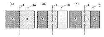
- two or more kinds of adsorbent layers for example, A
- adsorbent layers having different average pore diameters of adsorbents such as layers, B layers, C layers, and D layers
- the relative vapor pressure indicated by the range in which the amount of change in the saturated adsorption amount when the relative vapor pressure changes by 0.15 is maximized in the order of A layer ⁇ B layer ⁇ C layer.
- L indicates the MD center line.
- FIG. 3 shows the arrangement side of the adsorbent layer of the adsorbent sheet provided with two kinds of adsorbent layers, and the adsorbent sheet 1A of FIG. ) Is an ABC arrangement, the band width of each layer is the same and left-right asymmetric.
- the adsorbing sheet 1C in FIG. 3C is asymmetrical due to the ABA arrangement and the band width of each layer being different.
- the adsorbing sheet 1C is asymmetric in left and right because the layer structure itself is ABA and is bilaterally symmetric but the band width is different.
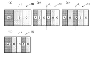
- FIG. 4 shows the arrangement side of the adsorbent layer of the adsorbent sheet provided with three kinds of adsorbent layers, and the adsorbing sheet 1D of FIG. 4 (a) has an ABC arrangement, so that FIG. 4E is an ABCABC arrangement, and the adsorption sheet 1F of FIG. 4C is an ABABC arrangement, the band width of each layer is the same and asymmetrical, and the adsorption sheet 1G of FIG. As a result of the ABCAB arrangement, the band width of each layer is different, resulting in left-right asymmetry.
- FIG. 5 shows such an adsorbent layer arrangement side
- portion X shows a strip-like portion where the adsorbent layer is not present and the base material is exposed.
- the adsorbing sheet 1H in FIG. 5 (a) is asymmetrical due to the AXBXC arrangement
- FIG. 5 (b) 1I is asymmetrical due to the AXB arrangement.
- the arrangement of the adsorbent layer is particularly according to the magnitude of the relative vapor pressure indicated by the range in which the amount of change in the saturated adsorption amount becomes maximum when the relative vapor pressure changes by 0.15 in the water vapor adsorption isotherm at 25 ° C. It is preferable to arrange them, and it is preferable to arrange them so as to gradually increase or gradually decrease like ABC or CBA.
- the feature of the present invention is that, in the water vapor adsorption isotherm at 25 ° C., the relative vapor pressure is in the range of 0.01 to 0.95, and the amount of change in the saturated adsorption amount is maximum when the relative vapor pressure changes by 0.15.
- a range of relative vapor pressure (hereinafter referred to as “maximum adsorption humidity range”) is intentionally changed on the right and left sides of the MD center line, and the relative vapor pressure differs by 0.05 or more on the left and right. It is preferable. Therefore, even when the smallest A layer exists between the B layer and the C layer as in the BAC, the A layer has a sufficiently small bandwidth ratio compared to either the B or C layer. Can be used without much difference in performance.
- suction element from an adsorption sheet it is preferable to provide an adsorbent layer on both surfaces of a base material.
- the adsorbent layers on both surfaces of the substrate By providing the adsorbent layers on both surfaces of the substrate, the area of the adsorbent layers exposed in the cells of the honeycomb is increased, and an improvement in the performance of the adsorbing element can be expected.
- the flow direction of the fluid to be treated such as air to be treated is uniform on one side and the other side of the sheet, so the adsorbent layer is arranged on one side of the substrate.
- the adsorbent layer on one side is arranged in the order of ABC (maximum adsorption humidity region A layer ⁇ B layer ⁇ C layer), and the adsorbent layer on the other side is A′B′C ′ (maximum adsorption humidity).
- ABC maximum adsorption humidity region A layer ⁇ B layer ⁇ C layer
- A′B′C ′ maximum adsorption humidity
- the band width of one adsorbent layer is excessively small, the effect of providing this adsorbent layer cannot be sufficiently obtained. Therefore, the band width of the adsorbent layer is 10 mm or more, and the adsorbent sheet itself It is preferable to determine appropriately according to the width and the number of adsorbent layers provided. Moreover, since the adsorption
- the method for producing the adsorption sheet of the present invention is not particularly limited, but for each adsorbent layer having a different average pore diameter, the adsorbent and the organic binder, and the various additives and fillers used as necessary, A coating liquid (hereinafter sometimes referred to as “adsorbent layer forming coating liquid” or “slurry”) in which fibers or the like are dissolved or dispersed in an appropriate solvent or dispersion medium is prepared, and this adsorbent layer forming coating is prepared.
- a method in which the liquid is applied to the substrate in a stripe shape is preferable.
- water is preferably used, but for the purpose of lowering the surface tension, glycerins, cellosolves, alcohols, ketones, esters, ethers.
- glycerins glycerins, cellosolves, alcohols, ketones, esters, ethers.
- aromatic hydrocarbons One kind or two or more kinds of aromatic hydrocarbons can be used.
- adsorbent layer forming coating solution can be used as a method for applying the adsorbent layer forming coating solution to the substrate.
- a knife coater is preferably applied by a knife coater, roll coater, spray coater, or bar coater.
- a knife coater is preferable to form a plurality of adsorbent layers with the same thickness at the same time.
- a roll knife coater is particularly preferable.
- a separator is installed on the back plate to form a portion where the liquid accumulates (sometimes called a liquid dam), and an adsorbent layer is formed on each liquid dam.
- a method in which two or more kinds of adsorbent layer forming coating liquids are applied in a stripe pattern onto a substrate that is continuously run while the coating liquid is placed therein is preferred.
- the method of performing stripe coating similarly using the knife (blade) provided with the some ink pot is preferable.
- the application method using such equipment has the advantage that a plurality of adsorbent layers can be applied simultaneously at the same time, so that the application process can be reduced and the band ratio of the plurality of application layers can be changed relatively easily. Yes, it is preferable in terms of compatibility with various types and productivity.
- the adsorbent layers can be arranged side by side without being laminated, the surface area of the adsorbent layers can be used effectively, and it is advantageous in that peeling between the layers hardly occurs. Furthermore, as an advantage of the coating method using the above equipment, it is difficult to cause clogging as compared with the case where a spray or the like is used.
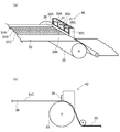
- FIGS. 6 (a) and 6 (b) are explanatory diagrams showing a method of applying the adsorbent layer forming coating solution onto the base material by a comma coater, in which 20 is a coating device (comma coater), A back plate 21, an applicator roll 23, and a backup roll 24 are provided.
- the back plate 21 is partitioned by a separator 22, and each adsorbent layer forming coating liquid 25 (25A, 25B, 25C) is formed in each formed liquid dam section. ) Is filled.
- the back plate 21 is divided into three equal parts by the two separators 22, but the separators can be used by appropriately moving according to the number of adsorbent layers to be formed and the band width.
- the base material 30 is fed from a base material roll (not shown) by the backup roll 24, and the applicator roll 23 is applied with the coating liquids 25A, 25B, 25C for forming the adsorbent layer to form the respective adsorbent layers. Films 31A, 31B, 31C are formed on the substrate.
- a multicolor knife coater 40 having a structure as shown in FIG.
- the multicolor knife coater 40 is filled with different coating liquids 35A, 35B, and 35C in the coating liquid pots 32A, 32B, and 32C separated by the separator (partition plate) 31, respectively.
- Each of the coating liquids 35A to 35C is stripe-coated with a knife (blade) 36 on the moving substrate 30 to form the coating films 31A, 31B, and 31C, respectively.
- the separator (partition plate) 31 can be used by appropriately moving according to the number of adsorbent layers to be formed and the band width.
- an adsorbent layer is made by hardening a coating film according to the hardening method of the used organic binder. It is formed.
- the adsorbent sheet of the present invention is preferably selected from the adsorbent, organic binder, substrate, coating method and the like as described above in a bending resistance test by a cylindrical mandrel method in accordance with JIS-K5600-5-1.
- a bending resistance test by a cylindrical mandrel method in accordance with JIS-K5600-5-1.
- the bending resistance is larger than 10 mm, it is difficult to shape the adsorption sheet into a honeycomb shape, a cylindrical shape, or other shapes in use as an adsorption sheet.
- the bending resistance is preferably 5 mm or less, but the lower limit is usually about 2 mm.
- the adsorbing sheet of the present invention is excellent in flexibility, it can be further processed into fins and the like of various heat exchangers by corrugating, embossing, louvering, punching, and the like.
- a ventilation element such as a desiccant rotor can be manufactured by stacking a plurality of corrugated sheets of the adsorbing sheet of the present invention or winding a corrugated sheet to form a honeycomb-shaped adsorbing element. It can be effectively used for an air conditioner or the like.
- the air to be treated has a relative humidity range (maximum adsorbing humidity range) in which the amount of change when the relative vapor pressure changes is maximum.
- the regeneration air preferably flows in from the lower humidity range where the relative humidity range (maximum adsorption humidity region) has the maximum amount of change when the relative vapor pressure changes. That is, it is preferable that the air to be treated and the air for regeneration are counterflows.
- the adsorption sheet adsorbing / desorbing method of the present invention can be applied to the fluid to be treated (from the left or right direction of the MD center line in the direction crossing the MD direction (that is, the extending direction of the striped adsorbent layer)).
- a method of adsorbing by flowing air containing water vapor) and desorbing by flowing a regeneration medium (for example, dry air) from the opposite direction is applied.
- adsorption process in which the fluid to be treated flows from the material layer forming side to the adsorbent layer forming side with the smallest adsorption humidity range, and an adsorbent with the largest adsorption humidity range from the adsorption layer forming side with the smallest adsorption humidity range It is preferable to perform a desorption step of flowing the reproduction medium toward the layer forming side because the adsorption / desorption amount per unit time can be greatly improved. That is, as described above, the adsorption sheet of the present invention is saturated adsorption when the relative vapor pressure is changed by 0.15 and the relative vapor pressure is in the range of 0.01 to 0.95 on the 25 ° C. water vapor adsorption isotherm.
- the relative vapor pressure range in which the amount of change in the amount is the maximum is different by 0.05 or more on the right side and the left side of the MD center line.
- the fluid to be treated for example, air containing water vapor, etc.
- the medium for regeneration for example, dry air. That is, it is preferable to perform desorption by flowing from the lower side to the higher side of the relative vapor pressure range in which the amount of change in the saturated adsorption amount is maximum.
- the water vapor adsorption isotherm represents the saturated water vapor adsorption amount of the adsorption process measured at 25 ° C. with Bell Soap 18 (product of Nippon Bell Co., Ltd.). Plotted against vapor pressure.
- “Relative vapor pressure range in which the amount of change in the saturated adsorption amount on the right or left half is the maximum” refers to the adsorption isotherm of each adsorbent layer when there are multiple adsorbent layers on the right or left half of the sheet.
- a line was obtained by measurement, and an adsorption isotherm as the right or left half of the sheet was synthesized from the content of each adsorbent layer in the right or left half. Based on the water vapor adsorption isotherm thus determined, the relative amount of change in the saturated adsorption amount when the relative vapor pressure changes by 0.15 in the relative vapor pressure range of 0.01 to 0.95 is the maximum.
- the range of vapor pressure was determined on the graph, and the comparison was made on the left and right of the MD center line of the sheet.
- the “difference between the left and right relative vapor pressure ranges” takes a range of 0.15 as the range of the relative vapor pressures indicating the left and right maximum values, and is represented by a difference between lower limit values or a difference between upper limit values.
- Examples 1 to 3 and Comparative Examples 1 to 6 below as a base material, an aluminum foil having a thickness of 30 ⁇ m (JIS IN30 material H) (when heat-treated at 300 ° C. for 30 minutes in air) The weight reduction rate was 1% by weight or less).
- AQSOA registered trademark
- -Z02 which is ALPO-based zeolite as an adsorbent (product name of Mitsubishi Plastics, CHA type, average particle size: 3 ⁇ m, average pore size: 0.38 nm) ) Containing an adsorbent layer (hereinafter referred to as “Z02 layer”) in the left half of the MD center line, and also AQSOA (registered trademark) -Z01 (product name of Mitsubishi Plastics, An adsorbent sheet in which an adsorbent layer (hereinafter referred to as “Z01 layer”) containing AFI type, average particle diameter: 3 to 5 ⁇ m, average pore diameter: 0.73 nm) is arranged on the right half of the MD center line is manufactured.
- Z01 layer An adsorbent sheet in which an adsorbent layer (hereinafter referred to as “Z01 layer”) containing AFI type, average particle diameter: 3 to 5 ⁇ m, average pore diameter: 0.73 nm
- the band width ratio (area ratio) between the Z02 layer and the Z01 layer viewed from the surface of the sheet is 1: 1.
- AQSOA-Z02 and Z01 show “S-shaped” adsorption isotherms, and the relative vapor pressure is 0.15 in the range of the relative vapor pressure 0.01 to 0.5 in the water vapor adsorption isotherm measured at 25 ° C.
- Adsorption amount changes when changed are 0.26 g / g and 0.18 g / g, respectively.
- DISPERBYK190 BIC Chemie Japan Co., Ltd. product name, nonvolatile content: 40 wt% aqueous solution
- adipic acid dihydrazide as an agent
- EPICLON as a binder
- An emulsion (average particle size: 0.5 ⁇ m, solid content: 45% by weight, nonion) of EXA-4816 (DIC Corporation product name) was mixed.
- Z02 slurry an aqueous solution obtained by diluting TAFIGEL PUR61 (manufactured by MUNZING CHEMIE, nonvolatile content: 25% by weight, urethane-based thickener) was added twice, and the mixture was sufficiently stirred, and a slurry for forming a Z02 layer (Hereinafter referred to as “Z02 slurry”).
- a separator is installed in the liquid dam part of the variable bird film applicator KP-K3545M004 (manufactured by Elcometer) to coat different types of slurry on the left and right, and Z02 slurry and Z01 slurry are filled on the left and right of the separator, respectively. It was applied on the material.
- the coating film was dried and then cured by heating at 160 ° C. for 1 hour, and trimming was performed so that the band width ratio (area ratio) of the Z01 layer and the Z02 layer viewed from the sheet surface was 1: 1.
- the sheet dimensions were 80 mm in the MD direction and 100 mm in the TD direction.
- the thicknesses of the Z01 layer and the Z02 layer were 100 to 110 ⁇ m, and the saturated adsorption amount of the sheet maintained 90% or more of the saturated adsorption amount of the adsorbent contained. Further, the saturation when the relative vapor pressure of the water vapor adsorption isotherm at 25 ° C. on the right side (Z01 layer) shown in FIG. 7A changes by 0.15 in the range of 0.01 to 0.95. The range of the relative vapor pressure where the amount of change in the adsorption amount is the maximum is 0.11 to 0.26, the left side (Z02 layer) is 0.01 to 0.16, and is 0.00 on the left and right of the MD center line L. 1 different.
- Example 2 As shown in FIG. 7 (b), activated alumina KC-501 (product name, average particle size: 1.5 ⁇ m, average pore size: about 3 nm) as an adsorbent and spherical silica gel sunspheres
- Three types of adsorbents a silica gel / active alumina mixed layer containing H-32 (AGC S-Tech Co., Ltd., product name, average particle size: 3 ⁇ m, average pore size: about 25 nm), Z01 layer, and Z02 layer
- Activated alumina KC-501 and Sunsphere H-32 show the "type IV" adsorption isotherm in the IUPAC classification, and the relative vapor pressure ranges from 0.01 to 0.5 in the water vapor adsorption isotherm measured at 25 ° C.
- the adsorption amount changes when the relative vapor pressure changes by 0.15 are 0.04 g / g and 0.04 g / g, respectively.
- silica gel / active alumina mixed slurry 20 g of activated alumina KC-501, 8 g of Sunsphere H-32, 54 g of ion-exchanged water, 1.6 g of DISPERBYK190, and an emulsion of jER1256 (average particle size: 0.5 ⁇ m, solid content: 45% by weight, nonion 9.6 g was mixed.
- aqueous solution in which TAFIGEL PUR61 is diluted twice is added, and stirred sufficiently to form a silica gel / active alumina mixed layer slurry (hereinafter referred to as “silica gel / active alumina mixed slurry”).
- Example 2 ⁇ Production of sheet>
- the liquid dam was divided by a separator and applied to the substrate.
- the layer thickness of each layer was 100 to 110 ⁇ m, and the saturated adsorption amount of the sheet maintained 90% or more of the saturated adsorption amount of the adsorbent contained.
- the relative vapor pressure of the water vapor adsorption isotherm at 25 ° C. on the right side (Z01 layer and silica gel / activated alumina mixed layer) shown in FIG. 7B is 0 in the range of 0.01 to 0.95.
- the range of relative vapor pressure with the maximum amount of saturated adsorption when changed is 0.70 to 0.85, and the left side (Z02 layer and Z01 layer) is 0.01 to 0.16. , 0.69 on the left and right of the MD center line L.
- the adsorbent contains KD-PWSP (activated carbon product name, coconut shell activated carbon, average particle diameter: 6 ⁇ m, average pore diameter: 3 nm) which is activated carbon.
- An adsorption sheet was prepared in which the activated carbon layer was arranged in the right half and the Z02 layer was arranged in the left half.
- the band width ratio (area ratio) between the Z02 layer and the activated carbon layer is 1: 1.
- Activated carbon KD-PWSP shows a “V-type” adsorption isotherm in the IUPAC classification, and the relative vapor pressure is 0.1 to 0.5 in the range of the water vapor adsorption isotherm measured at 25 ° C.
- the change in the amount of adsorption when 15 is changed is 0.06 g / g.
- activated carbon slurry 20 g of activated carbon KD-PWSP, 37 g of ion-exchanged water, 2 g of DISPERBYK190, and 5 g of an emulsion of jER1256 (average particle size: 0.5 ⁇ m, solid content: 45% by weight, nonion) were mixed. To this mixed solution, 1.5 g of an aqueous solution in which TAFIGEL PUR61 was diluted twice was added and stirred sufficiently to obtain a slurry for forming an activated carbon layer (hereinafter referred to as “activated carbon slurry”).
- Example 2 ⁇ Production of sheet>
- the liquid dam was divided by a separator and applied to the substrate.
- the layer thickness of each layer was 100 to 110 ⁇ m, and the saturated adsorption amount of the sheet maintained 90% or more of the saturated adsorption amount of the adsorbent contained.
- saturation is obtained when the relative vapor pressure of the water vapor adsorption isotherm at 25 ° C. on the right side (activated carbon layer) shown in FIG. 7C changes by 0.15 in the range of 0.01 to 0.95.
- the relative vapor pressure range in which the amount of change in the adsorption amount is maximum is 0.52 to 0.67, the left side (Z02 layer) is 0.01 to 0.16, and is 0.00 on the left and right of the MD center line L. 51 different.
- Example 1 As shown in FIG. 7D, an adsorption sheet having a Z02 layer alone was produced. The procedure was the same as in Example 1 except that the adsorbent layer was one type of Z02 layer. The thickness of the Z02 layer was 100 ⁇ m, and the saturated adsorption amount of the sheet maintained 90% or more of the saturated adsorption amount of the adsorbent contained. In addition, when the relative vapor pressure of the water vapor adsorption isotherm at 25 ° C. of the Z02 layer in FIG. 7D is changed by 0.15 in the range of 0.01 to 0.95, the saturation adsorption amount changes. The range of the relative vapor pressure with the maximum amount is 0.01 to 0.16 on both the left and right sides of the sheet, and is a difference of less than 0.05 on the left and right of the MD center line L.
- FIG. 7E an adsorption sheet having a Z01 layer alone was produced.
- the procedure was the same as in Example 1 except that the adsorbent layer was one kind of Z01 layer.
- the thickness of the Z01 layer was 100 ⁇ m, and the saturated adsorption amount of the sheet maintained 90% or more of the saturated adsorption amount of the adsorbent contained.
- the change in the saturated adsorption amount when the relative vapor pressure of the water vapor adsorption isotherm at 25 ° C. of the Z01 layer in FIG. 7 (e) changes by 0.15 in the range of 0.01 to 0.95.
- the range of the relative vapor pressure with the maximum amount is 0.11 to 0.26 on both the left and right sides of the sheet, and is a difference of less than 0.05 on the left and right of the MD center line L.
- Z01 / Z02 mixed layer an adsorption sheet in which Z01 and Z02 were mixed in the same layer (hereinafter referred to as “Z01 / Z02 mixed layer”) at a ratio of 1: 1 was prepared.
- the slurry for forming the Z01 / Z02 mixed layer was prepared by mixing the Z01 slurry and the Z02 slurry prepared in Example 1 at a weight ratio of 1: 1, and Example 1 except that the adsorbent layer was one kind. The same procedure was followed.
- the thickness of the Z01 / Z02 mixed layer was 100 ⁇ m, and the saturated adsorption amount of the sheet maintained 90% or more of the saturated adsorption amount of the adsorbent contained.
- the saturated adsorption when the relative vapor pressure of the water vapor adsorption isotherm at 25 ° C. of the Z01 / Z02 mixed layer in FIG. 7 (f) changes by 0.15 in the range of 0.01 to 0.95.
- the range of the relative vapor pressure in which the amount of change is maximum is 0.06 to 0.21 on both the left and right sides of the sheet, and is a difference of less than 0.05 on the left and right of the MD center line L.
- Example 4 As shown in FIG. 7G, an adsorption sheet was produced in which the Z02 layer was placed symmetrically in the center and the Z01 layer was placed on the left and right sides with the Z02 layer interposed therebetween. The same procedure as in Example 2 was performed except that the Z01 slurry and the Z02 slurry were used.
- the band width ratio (area ratio) of the Z01 layer, the Z02 layer, and the Z01 layer is 1: 2: 1.
- the layer thickness of each layer was 100 to 110 ⁇ m, and the saturated adsorption amount of the sheet maintained 90% or more of the saturated adsorption amount of the adsorbent contained. Further, the relative vapor pressure of the water vapor adsorption isotherm at 25 ° C.
- Example 5 As shown in FIG. 7 (h), an adsorption sheet having a single silica gel / active alumina mixed layer was produced. The procedure was the same as in Example 2 except that the adsorbent layer was one type of silica gel / active alumina mixed layer. The thickness of the silica gel / active alumina mixed layer was 100 ⁇ m, and the saturated adsorption amount of the sheet maintained 90% or more of the saturated adsorption amount of the adsorbent contained. Further, the saturation when the relative vapor pressure of the water vapor adsorption isotherm at 25 ° C. of the silica gel / activated alumina mixed layer in FIG.
- the range of the relative vapor pressure where the amount of change in the adsorption amount is maximum is 0.69 to 0.84 on both the left and right sides of the sheet, and is a difference of less than 0.05 on the left and right of the MD center line L.
- FIG. 7 (i) an adsorption sheet having an activated carbon layer alone was produced.
- the same procedure as in Example 3 was performed except that the adsorbent layer was one type of activated carbon layer.
- the activated carbon layer had a thickness of 100 ⁇ m, and the saturated adsorption amount of the sheet maintained 90% or more of the saturated adsorption amount of the adsorbent contained.
- the change in saturated adsorption amount when the relative vapor pressure of the water vapor adsorption isotherm at 25 ° C. of the activated carbon layer in FIG. 7 (i) is changed by 0.15 in the range of 0.01 to 0.95.
- the range of the relative vapor pressure with the maximum amount is 0.52 to 0.67 on both the left and right sides of the sheet, and is a difference of less than 0.05 on the left and right of the MD center line L.
- FIG. 5A 80 mm ⁇ 80 mm ⁇ 100 mm obtained in each example using two rectangular aluminum plates 11 of 0.5 mm ⁇ 80 mm ⁇ 100 mm and two spacers 12 of 5 mm ⁇ 5 mm ⁇ 100 mm.
- the 100 mm suction sheet 10 was sandwiched so as to form a 5 mm ⁇ 70 mm ⁇ 100 mm air flow path, and was placed inside a vinyl chloride tube 13 having an inner diameter of about 80 mm, as shown in FIG.
- ⁇ Adsorption process> The air to be treated was 23.2 ° C., 21.15 ° C. DP, and about 80% RH. Moreover, the air volume which flows through the vinyl chloride pipe
- the adsorbent sheet was allowed to stand in a closed container filled with water, and the state where no increase in weight was observed was regarded as a saturated state (reaching rate: 0%), and the change in the reaching rate with time was measured.
- ⁇ Achievement rate after 100 seconds> The elapsed time is plotted on the horizontal axis and the arrival rate is plotted on the vertical axis, a logarithmic approximation curve is drawn, the adsorption / desorption rate is evaluated by the magnitude relationship of the arrival rate after 100 seconds indicated by the approximation curve, and the results are shown in Table 1. It was.
- Table 1 shows the results of the adsorption process and the desorption process.
- “L ⁇ R” indicates that the air to be treated has flowed from the right side to the left side in FIGS. 7A to 7C
- “L ⁇ R” indicates that the left side to the right side. Indicates that the processing air has flowed.
- Example 1 is an adsorbent sheet having two adsorbent layers (Z02 layer and Z01 layer) having different average pore diameters, and is an adsorbent sheet arranged 1: 1 in a left-right asymmetric manner.
- Comparative Example 1 is an example of only the Z02 layer (left-right symmetric) among the adsorbents used in Example 1
- Comparative Example 2 is an example of only Z01 (left-right symmetric)
- Comparative Example 3 includes these
- the adsorbent sheet was prepared by mixing the same amount of both adsorbents as in Example 1 and providing a single layer (symmetrical).
- Comparative Examples 1 to 3 when the air to be treated is passed through the measuring element, there is no difference in the adsorption arrival rate (adsorption speed). It was found that Example 1 was more efficiently desorbed than any of -3.
- Example 1 was so superior at the time of desorption is that heat transfer and mass transfer are involved in a complicated manner, and thus cannot be fully explained.
- Comparative Examples 1 to 3 Although desorption gradually proceeds from the adsorbent on the air inlet side, there are areas where desorption cannot follow due to an increase in humidity in the air and a decrease in temperature of the adsorbent due to latent heat of vaporization.
- the Z02 layer, Z01 The desorption characteristics of each layer can follow the humidity distribution, and desorption progresses at the same time in each layer. Therefore, it is assumed that the desorption arrival rate of the entire sheet is high.
- Example 1 the air to be treated is applied to the sheet from the side having the higher relative vapor pressure to the side having the lower relative vapor pressure indicated by the range in which the amount of change in the saturated adsorption amount when the relative vapor pressure changes by 0.15 (L ⁇ R), and when desorption is performed in the opposite direction (L ⁇ R), apart from that, the relative range indicated by the maximum amount of change in saturated adsorption when the relative vapor pressure changes by 0.15
- arrival rate arrival rate
- the arrival rate was higher in L ⁇ R. This seems to be because L ⁇ R can be desorbed according to the humidity distribution in the element.
- the air flowing downstream in the initial stage of the desorption process is lowered in temperature by the latent heat on the upstream side and the humidity is also increased by the desorption water vapor, so that the adsorbent on the downstream side is adsorbed even at low relative humidity.
- the relative vapor pressure changes by 0.15 the relative vapor pressure range in which the amount of change in the saturated adsorption amount becomes the maximum is the adsorbent on the low humidity side
- the desorption is difficult to proceed. Become.
- the adsorbent on the downstream side is an adsorbent that does not adsorb in the low humidity region (that is, the relative vapor pressure range in which the amount of change in the saturated adsorption amount becomes maximum when the relative vapor pressure changes by 0.15 is high. Desorption is easier to proceed using an adsorbent on the humidity side. Therefore, in Example 1, when the desorption is L ⁇ R (adsorption is L ⁇ R), the performance is further improved as compared with the efficiency improvement when the adsorption layer is simply symmetrically provided. Seem.
- Comparative Example 4 is an example in which different adsorbent layers are provided symmetrically in a stripe shape, but by adjusting the wind direction as in Example 1, adsorption / desorption cannot be optimized. Therefore, it can be seen that it is preferable to make the left-right asymmetry.
- Example 4 ⁇ Manufacture of adsorption sheet> 30 kg each of Z01 slurry and Z02 slurry were prepared at the same mixing ratio as in Example 1, and applied on an aluminum foil (JIS 1N30 material H) with a thickness of 30 ⁇ m and a width of 500 mm with a comma coater, dried and heat-cured, An adsorbent layer having a width of 480 mm was formed. At the time of application, a movable separator was installed at the center of the liquid dam so that the width of the Z01 layer and the Z02 layer was 1: 1, and the liquid dam was divided.
- the line speed was 20 m / min, and the applicator roll clearance was adjusted so that the dry thickness of the Z01 and Z02 layers was 70 ⁇ m.
- the thickness of the movable separator was adjusted so that there was no uncoated portion at the boundary between the Z01 layer and the Z02 layer. At this time, when the thickness of the contact portion of the separator with the base material was 3 mm or less, it was confirmed that the coating liquid wraps around the interface portion and the uncoated portion disappears.
- the drying oven was 25 m, and the temperature was set in the range of 120 to 130 ° C. After the application was completed, a Z01 layer and a Z02 layer having a dry thickness of 70 ⁇ m were applied to the back surface in the same procedure.
- the single-stage corrugated sheet obtained above was wound around a core of ⁇ 38 mm and rolled up to ⁇ 320 mm to obtain a rotor-like element.
- corrugating and subsequent winding could be performed without causing cracking or peeling of the adsorbent layer.
- the single-stage corrugated sheet has a structure in which the Z01 layer and the Z02 layer are separately applied in the right half and the right half with respect to the MD center line.
- the obtained adsorbing sheet has a Z01 layer and a Z02 layer separately coated on the right half and the left half with respect to the MD center line.
- the Z02 layer has an average thickness of 70 ⁇ m (total thickness of 100 ⁇ m) and the Z01 layer of 114 ⁇ m (total thickness of 144 ⁇ m) in one application. became.
- the edge part was thicker than the center part of the sheet
- the adsorbent sheet had an average thickness difference of 30 ⁇ m between the right and left sides of the MD center line.
- ⁇ Bonding in rotor-shaped element production> By applying an adhesive to the convex part of the single-stage corrugated sheet obtained in the above-mentioned single-stage corrugated sheet and winding it around a 38 mm diameter paper tube with the MD direction as the circumferential direction, a rotor-shaped honeycomb element having a diameter of 320 mm is obtained. It was. The state of the obtained honeycomb element was observed, and “ ⁇ ” was evaluated when the sheet was bonded, and “X” was evaluated when defective bonding was observed.
- Example 6 In the same procedure as in Example 5, the left and right thickness difference of the MD center line of the suction sheet was adjusted to obtain an suction sheet with an average thickness difference of 9 ⁇ m between the left and right. The resulting suction sheet was the same as in Example 5. Evaluation was performed and the results are shown in Table 2.
- Example 7 In the same procedure as in Example 5, the left and right thickness difference of the MD center line of the suction sheet was adjusted to obtain an suction sheet having an average thickness difference of 19 ⁇ m on the left and right. The resulting suction sheet was the same as in Example 5. Evaluation was performed and the results are shown in Table 2.
- Example 8 In the same procedure as in Example 5, the thickness difference between the left and right of the MD center line of the suction sheet was adjusted to obtain a suction sheet having an average thickness difference of 3 ⁇ m between the left and right. In Examples 5 to 7, there was no uncoated portion at the boundary between the Z02 layer and the Z01 layer, but the adsorption sheet of Example 8 was used at the boundary between the Z02 layer and the Z01 layer by using a separator having a thickness of 10 mm. An uncoated portion having a width of 8 mm was provided. The obtained adsorption sheet was evaluated in the same manner as in Example 5, and the results are shown in Table 2. In this suction sheet, slack wrinkles occurred in the uncoated part during winding.
- Example 8 In the same procedure as in Example 5, the left and right thickness difference of the MD center line of the adsorption sheet is adjusted to obtain an adsorption sheet having an average thickness difference of 24 ⁇ m on the left and right. The obtained adsorption sheet is the same as in Example 5. Evaluation was performed and the results are shown in Table 2.
- the adsorption sheets of Example 5 and Example 6 can be processed without causing defects in any process up to the formation of a rotor-like element.
- the adsorption sheet of Example 7 could be processed as long as it was a single-stage corrugated sheet.
- the suction sheet of Example 8 was able to be processed into a one-stage corrugated sheet and a rotor-like element, although slack wrinkles occurred in the uncoated part during winding of the suction sheet.
- the suction sheet of Comparative Example 8 was difficult even by winding the suction sheet.
- the average thickness difference between the right side and the left side of the MD center line is 20 ⁇ m or less, and further, when processing up to the rotor-like element is necessary, the thickness It can be seen that the difference is preferably 10 ⁇ m or less.
- Example 9 The same slurry and substrate as in Example 1 were used, and in the same procedure, the band width ratio (area ratio) of the Z01 layer and the Z02 layer was 1: 1, and the thickness of each adsorbent layer was 100 ⁇ 3 ⁇ m.
- An adsorption sheet was prepared. Using the obtained adsorbing sheet, the adsorbent layer is turned outside and the sheet is circulated in the MD direction (longitudinal direction), and bent by the cylindrical mandrel method in accordance with JIS-K5600-5-1 as described above. Tests were performed to determine the minimum mandrel diameter that could be bent without defects. The results are shown in Table 3.
- Example 10 In the same manner as in Example 9, an adsorbent sheet having an adsorbent layer thickness of 200 ⁇ 5 ⁇ m was obtained. The obtained adsorbent sheet was subjected to a bending test in the same manner as in Example 9, and the results are shown in Table 3.
- Example 11 In the same manner as in Example 9, an adsorbent sheet having an adsorbent layer thickness of 300 ⁇ 5 ⁇ m was obtained. The obtained adsorbent sheet was subjected to a bending test in the same manner as in Example 9, and the results are shown in Table 3.
- Example 12 The same slurry and substrate as in Example 2 were used, and in the same procedure, in a striped form in which the band width ratio (area ratio) of the silica gel / active alumina mixed layer, the Z01 layer, and the Z02 layer was 1: 1: 1. Then, an adsorption sheet having a thickness of 100 ⁇ 3 ⁇ m of each adsorbent layer was produced. The obtained adsorption sheet was subjected to a bending test in the same manner as in Example 9, and the results are shown in Table 3.
- Example 13 In the same manner as in Example 12, an adsorbent sheet having an adsorbent layer thickness of 200 ⁇ 5 ⁇ m was obtained. The obtained adsorbent sheet was subjected to a bending test in the same manner as in Example 9, and the results are shown in Table 3.
- Example 14 An adsorption sheet having an adsorbent layer thickness of 300 ⁇ 5 ⁇ m was obtained in the same manner as in Example 12. The obtained adsorption sheet was subjected to a bending test in the same manner as in Example 9, and the results are shown in Table 3.
- the thickness of the adsorbent layer is preferably 300 ⁇ m or less. I understand.
Landscapes
- Chemical & Material Sciences (AREA)
- Analytical Chemistry (AREA)
- Organic Chemistry (AREA)
- Chemical Kinetics & Catalysis (AREA)
- Inorganic Chemistry (AREA)
- Drying Of Gases (AREA)
- Solid-Sorbent Or Filter-Aiding Compositions (AREA)
- Central Air Conditioning (AREA)
Abstract
基材上に、2種類以上の吸着材層を有する吸着シートであって、吸着性能、加工性能、量産性をすべて満足し、吸着素子の原シートとなり得る吸着シートを提供する。基材上に、含有される吸着材の平均細孔径が互いに異なる2種以上の吸着材層をし、下記(I)~(V)を満足する吸着シート。 (I)吸着材層は、有機バインダーと吸着材とを含み、有機バインダーの含有量が10重量%以上 (II)吸着材層は、基材の同一面上にストライプ状に設けられている (III)吸着材層は、吸着シートのMD方向に沿う中心線に対して非対称に設けられている (IV)25℃の水蒸気吸着等温線において、相対蒸気圧が0.01~0.95の範囲で、相対蒸気圧が0.15変化したときの飽和吸着量の変化量が最大である相対蒸気圧の範囲が、中心線の右側と左側で0.05以上異なる (V)中心線の右側と左側で、平均厚みの差が20μm以下
Description
本発明は、2種類以上の吸着材層形成用塗布液をストライプ状に塗工することによって、2種以上の吸着材層を基材の同一面上に設けた吸着シート及びその製造方法と、この吸着シートを用いた吸着素子及びデシカント空調装置に関するものである。
ゼオライト、多孔性シリカ、活性アルミナ、活性炭に代表される吸着材は、調湿、脱臭、ガスの分離精製、吸着式ヒートポンプ等に利用されている。
特に調湿分野では、ハニカムローターに各種吸着材を担持させたデシカントローターが、デシカント空調装置に利用されている。
デシカント空調装置は、被処理空気を吸着素子に接触させて被処理空気中の水分を吸着素子に吸着させるための被処理空気の流通経路と、加熱源によって加熱された再生用空気を水分吸着後の吸着素子に接触させて吸着素子中の水分を脱着させて再生するための再生用空気の流通経路とを有し、吸着素子に被処理空気と再生用空気が交互に流通するように構成されたものである。デシカント空調装置では、吸着素子にて連続的な水分の吸着を行うと共に、同時に吸着素子に吸着した水分を脱着して再生することができる。従って、冷却減湿方式よりも省エネルギーであり、且つ空調空間の湿度を制御できる技術として実用価値が高いものである。
このようなデシカント空調装置においては、種々の作動流体と吸着材の組み合わせが考えられるが、例えば水と各種の吸着材を想定し、被処理空気の含水率が相対蒸気圧P/Psで表して0.4(40%RH)であり、再生用空気の含水率が相対蒸気圧で表して0.1(10%RH)であるとすると、水分の吸着平衡特性において、P/Psが少なくとも0.1~0.4の間でなるべく大きな吸着量変化を有する吸着材が必要となる。
図1,2は、各種吸着材の相対蒸気圧に対する吸湿量の変化(水蒸気吸着等温線)を示したものである。
現在、デシカントローターとしては、Y型ゼオライトを主体として構成された吸着素子が代表的ローターの一つであるが、図1に示すように、Y型ゼオライト吸着素子の除湿特性の特徴は、相対蒸気圧0.4(40%RH)以下の除湿動作範囲において吸着等温線がほぼ直線的であり、相対蒸気圧0.05(5%RH)以下で大きな吸着量変化を持つことである。これは、Y型ゼオライトの場合は吸着素子の再生を低い相対蒸気圧、つまり、より高い温度(例えば100℃以上)で行わなければならないことを意味する。
現在、デシカントローターとしては、Y型ゼオライトを主体として構成された吸着素子が代表的ローターの一つであるが、図1に示すように、Y型ゼオライト吸着素子の除湿特性の特徴は、相対蒸気圧0.4(40%RH)以下の除湿動作範囲において吸着等温線がほぼ直線的であり、相対蒸気圧0.05(5%RH)以下で大きな吸着量変化を持つことである。これは、Y型ゼオライトの場合は吸着素子の再生を低い相対蒸気圧、つまり、より高い温度(例えば100℃以上)で行わなければならないことを意味する。
近年、吸着素子に有用な吸着材として、図1,2に示したALPO系ゼオライトの様な、除湿操作において大きな吸着量変化を示す、いわゆるS字型の吸着特性を有するゼオライトが見出されており、例えば特許文献2~5に記載されているものが挙げられる。これらALPO系ゼオライトを使用することで、シリカゲルや従来のY型ゼオライトよりも吸着素子の再生温度を下げることが可能であることから、低温熱源の利用が期待されている。
図2からも明らかなように、従来の代表的吸着材であるシリカゲルは、相対蒸気圧0.1~0.4での飽和吸着量の変化は大きいとは言えないが、ALPO系ゼオライトは比較的低相対湿度(蒸気圧)側でS字型の吸着平衡特性を示し、相対蒸気圧0.1~0.4の範囲で飽和吸着量に大きな変化が見られる。
一方で、より高相対湿度(蒸気圧)側も含めた範囲(例えば、相対蒸気圧0.1~0.8)での飽和吸着量の変化を考えると、シリカゲルの方がALPO系ゼオライトより飽和吸着量の変化が大きい。つまり、マイクロ孔が主体であるゼオライトと、メソ孔が主体であるシリカゲルとでは、吸脱着可能な相対蒸気圧範囲が大きく異なっている。
このように、吸着材は親水性や細孔径によって吸脱着に有利な相対蒸気圧範囲が異なっていることから、異なる吸着材を各々有効に使い分けることにより、デシカントローターの除湿効率を向上させることができると考えられる。即ち、一般的に、吸着素子の内部を流通する被処理空気は、吸着素子の入口から出口にかけて湿度と温度に勾配がある。従って、吸着素子の各場所における被処理空気、且つ再生用空気の条件に合わせて最適な吸着材を配置することで、吸着素子の除湿性能が向上することが期待できる。
このように異なる吸着材を効率的に利用するための構成として、特許文献1には均一なナノ細孔径を有するシリカ系多孔体の細孔径を、被処理空気の入口側から出口側に向かって徐々に又は段階的に小さくなるように配置した吸着素子が提案されている。特許文献1に例示されている吸着素子は、細孔径が均一である吸着素子よりも、デシカントローターの限られた吸湿処理-再生時間内で、多くの水蒸気を吸脱着することが可能となる。この特許文献1では、ミセル-シリケート複合体の溶液を成形、乾燥、焼成して吸着素子を形成している。
また、特許文献5には、コルゲート型、ハニカム型、格子型などの多数の通気穴が設けられた通気構造体(通気エレメント)に水蒸気吸着用の吸着材を塗布して吸着素子を構成し、ペルチェ素子と組み合わせたものが記載されており、該通気エレメントが、通気方向に従って2種以上の吸着材を塗り分けることが記載されているが、特許文献5では、所定の形状に成形されたエレメントに吸着材を塗布して通気エレメントを製造している。
しかし、特許文献1では、シリカ系多孔体を形成するために、ミセル-シリケート複合体の溶液を基材に塗布した後に、600℃以上で焼成する必要があり、基材は焼成温度に耐え得るセラミックス等に限定されるという問題があった。また、吸着材に関してもシリケートと同時焼成することができるものに限定されてしまい、特許文献1の技術をゼオライトや活性炭といった他の吸着材に適用し、更なる高機能化を図ることは困難であるという問題があった。
更に、吸着材層であるシリカ系多孔体は可撓性に乏しいため、基材とシリカ系多孔体からなるシートを作製した後に、ハニカム状に加工することは困難であった。このため、ハニカム状の素子を得る場合は、予めハニカム状に加工した基材に、ディップ等の方法でミセルーシリケート複合体の溶液を塗布する必要がある。しかしながら、このような複雑形状の基材への異種吸着材のパターン塗布は困難であり、量産性に乏しく、コスト高になるという問題があった。
そのため、ハニカム等の形状への加工が容易な、十分な可撓性を有した吸着シートが求められていた。
上記の通り、一つの吸着素子中に異種の吸着材を塗り分けて配置するコンセプトや、吸着材を塗布した吸着シートをコルゲート加工するなどして吸着素子を製造する方法は公知であったが、予めストライプ状に塗工した吸着シートを原シートとし、コルゲート加工することは従来行われていなかった。
この理由としては、以下のことが挙げられる。
吸着シートの仕様に関しては、吸着素子を得るための一連の工程を実際に行い、得られた吸着素子を評価・検討した上で得られる知見を元に決定する必要があり、不明な点が多く、特に、吸着シートの層構成、材料組成、各吸着材配置部分の吸着特性と配置パターンの設計が困難である。また、コルゲート型等の形状に予め成形されたエレメントに対して2種以上の吸着材を塗布する場合、通常、吸着材ごとに別々に塗布を行うため、塗布厚みに差が出たり、配置部分の界面や隣接部の構成が難しかったり、塗布される吸着材の量、厚みの調整が困難であったり、またエレメントの通気穴の閉塞等の問題もある。このようなことから、エレメントに吸着材を設ける場合に適当な塗布装置は無く、熟練した人手による塗布が必要であった。
また、本発明により解決された、基材上に複数の吸着材をストライプ状に設けることにより生じる種々の技術課題については、従来技術から容易に類推することは出来ない上に、本発明のように、2種類以上の吸着材層形成用塗工液をストライプ状に塗布し、目的の仕様の吸着シートを得る具体的な製造方法も、従来技術から容易に類推することは困難であった。
吸着シートの仕様に関しては、吸着素子を得るための一連の工程を実際に行い、得られた吸着素子を評価・検討した上で得られる知見を元に決定する必要があり、不明な点が多く、特に、吸着シートの層構成、材料組成、各吸着材配置部分の吸着特性と配置パターンの設計が困難である。また、コルゲート型等の形状に予め成形されたエレメントに対して2種以上の吸着材を塗布する場合、通常、吸着材ごとに別々に塗布を行うため、塗布厚みに差が出たり、配置部分の界面や隣接部の構成が難しかったり、塗布される吸着材の量、厚みの調整が困難であったり、またエレメントの通気穴の閉塞等の問題もある。このようなことから、エレメントに吸着材を設ける場合に適当な塗布装置は無く、熟練した人手による塗布が必要であった。
また、本発明により解決された、基材上に複数の吸着材をストライプ状に設けることにより生じる種々の技術課題については、従来技術から容易に類推することは出来ない上に、本発明のように、2種類以上の吸着材層形成用塗工液をストライプ状に塗布し、目的の仕様の吸着シートを得る具体的な製造方法も、従来技術から容易に類推することは困難であった。
本発明は、2種以上の吸着材層を基材の同一面上にストライプ状に設けてなる吸着シートであって、吸着性能、加工性能、量産性の要求特性をすべて満足し、加工により各種の形態の吸着素子を製造するための原シートとしても用いることができる吸着シートの仕様と製造方法、並びに、この吸着シートを用いた吸着素子及びデシカント空調装置を提供することを課題とする。
本発明者らは、上記課題を解決すべく鋭意検討を重ねた結果、吸着シートの吸着材の配置パターンが、MD方向(縦方向)に沿う中心線(MD中心線と称す)に対して非対称であって、該中心線の右側と左側で、吸着等温線が所定の関係であることによって、吸着物品として2種類以上の吸着材層を有することの優位性を得ることができること見出した。
更に、該中心線の右側と左側で、配置パターンや吸着特性が違っていながらも、平均厚みの差を所定の範囲内とすることで、セル間の空気漏れのない片段コルゲートシートやローター状素子を得ることが出来ることを見出した。具体的には、吸着シートを巻き取る工程では、シートの弛みが発生しにくくなり、シワやテレスコープ(シートの尾端がロールの軸方向にずれて、ロールエッジからはみ出すこと)といった不具合のない、ロール状の原シート(吸着材シート)が得られ、片段コルゲートシートの製造工程では、コルゲートシートとライナーシートを接着する際の圧力をシートの幅方向に均等に分散することができ、結果としてシートの幅方向の各部分において、強固に接着した片段コルゲートシートを得ることができる。また、片段コルゲートシートを巻き取る工程でも、巻き取り時の張力を幅方向に均一化でき、コルゲート-ライナー間の剥離を防止することができる。また、片段コルゲートシートの凸部に糊付けして、ローター状(ハニカム)素子を得る工程では、歪みによる剥離を防止することができる。
更に、該中心線の右側と左側で、配置パターンや吸着特性が違っていながらも、平均厚みの差を所定の範囲内とすることで、セル間の空気漏れのない片段コルゲートシートやローター状素子を得ることが出来ることを見出した。具体的には、吸着シートを巻き取る工程では、シートの弛みが発生しにくくなり、シワやテレスコープ(シートの尾端がロールの軸方向にずれて、ロールエッジからはみ出すこと)といった不具合のない、ロール状の原シート(吸着材シート)が得られ、片段コルゲートシートの製造工程では、コルゲートシートとライナーシートを接着する際の圧力をシートの幅方向に均等に分散することができ、結果としてシートの幅方向の各部分において、強固に接着した片段コルゲートシートを得ることができる。また、片段コルゲートシートを巻き取る工程でも、巻き取り時の張力を幅方向に均一化でき、コルゲート-ライナー間の剥離を防止することができる。また、片段コルゲートシートの凸部に糊付けして、ローター状(ハニカム)素子を得る工程では、歪みによる剥離を防止することができる。
本発明者らはまた、一定の耐屈曲性を発現するための、基材上の各吸着材層の厚みの上限を見出した。例えば、直径10mmの円筒マンドレルで欠陥無く屈曲できる吸着材層の厚みは、300μm以下であった。
本発明者らは更に、このような吸着シートの製造方法を検討した結果、ナイフコーター、特にロールナイフコーター(コンマコーター:ヒラノ・テクシード社登録商標)を用い、その液ダムをセパレーターにより仕切り、複数の塗布液を塗布することにより、効率良く製造できることを見出した。すなわち、粘度や固形分の異なる複数の塗布液を、非対称で多様なストライプパターンに塗布する際、ナイフ又はアプリケーターロールをTD方向(横方向:MD方向と直交方向)に傾けることで、MD中心線の右側と左側の塗布厚みを簡単に調整することが可能であり、セパレーターを設置するだけで、多様なストライプパターンに対応できる。更に、薄いセパレーターを使用することで、隣接する吸着材層の境界部に塗布液をまわり込ませ、未塗工部分を残さないようにすることも可能であり、これにより、巻取り時の張力により未塗工部に発生する欠陥や、吸着素子製造時の接着不良、ハニカム状素子のセル間の空気漏れを、効果的に防止することができる。
本発明はこのような知見に基づいて達成されたものであり、以下を要旨とする。
[1] 基材上に、含有される吸着材の平均細孔径が互いに異なる2種以上の吸着材層を有する吸着シートであって、下記(I)~(V)を満足することを特徴とする吸着シート。
(I)該2種以上の吸着材層は、有機バインダーと吸着材とを含み、該吸着材層中の該有機バインダーの含有量が10重量%以上である。
(II)該2種以上の吸着材層は、該基材の同一面上にストライプ状に設けられている。
(III)該2種以上の吸着材層は、該吸着シートのMD方向に沿う中心線に対して、非対称に設けられている。
(IV)該吸着シートは、25℃の水蒸気吸着等温線において、相対蒸気圧が0.01~0.95の範囲で、相対蒸気圧が0.15変化したときの飽和吸着量の変化量が最大である相対蒸気圧の範囲が、前記中心線の右側と左側で0.05以上異なっている。
(V)該吸着シートは、前記中心線の右側と左側で、平均厚みの差が20μm以下である。
(I)該2種以上の吸着材層は、有機バインダーと吸着材とを含み、該吸着材層中の該有機バインダーの含有量が10重量%以上である。
(II)該2種以上の吸着材層は、該基材の同一面上にストライプ状に設けられている。
(III)該2種以上の吸着材層は、該吸着シートのMD方向に沿う中心線に対して、非対称に設けられている。
(IV)該吸着シートは、25℃の水蒸気吸着等温線において、相対蒸気圧が0.01~0.95の範囲で、相対蒸気圧が0.15変化したときの飽和吸着量の変化量が最大である相対蒸気圧の範囲が、前記中心線の右側と左側で0.05以上異なっている。
(V)該吸着シートは、前記中心線の右側と左側で、平均厚みの差が20μm以下である。
[2] 該吸着材層の厚みは300μm以下であり、かつJIS-K5600-5-1に準拠した円筒形マンドレル法による耐屈曲試験において、マンドレル径10mmでクラック及び剥がれがみられない[1]に記載の吸着シート。
[3] 隣接する2種以上の吸着材層の境界部に未塗工部分が無い[1]又は[2]に記載の吸着シート。
[4] 該2種以上の吸着材層が、該基材の両面にそれぞれ設けられている[1]ないし[3]の何れかに記載の吸着シート。
[5] 該基材が、空気中、300℃で30分間の熱処理をしたときの重量減少率が1重量%以下である熱可塑性樹脂、又は金属よりなることを特徴とする[1]ないし[4]の何れかに記載の吸着シート。
[6] ナイフコーターの液ダムを、1個以上のセパレーターで仕切り、それぞれ吸着材と有機バインダーを含む2種以上の吸着材層形成用塗布液を別個に収容できる部分を設けてなるナイフコーターを用い、該2種以上の塗布液をストライプ状に同時に塗布する工程を含むこと特徴とする[1]ないし[5]の何れかに記載の吸着シートの製造方法。
[7] 該ナイフコーターが、ロールナイフコーターである[6]に記載の吸着シートの製造方法。
[8] [1]ないし[5]の何れかに記載の吸着シートを原シートとする吸着素子であって、被処理流体を、前記中心線の右側と左側のうち、前記相対蒸気圧が0.15変化したときの飽和吸着量の変化量が最大となる相対蒸気圧の範囲が高い側から低い側へ流して吸着を行い、再生用媒体を該被処理流体の流通方向と反対の方向に流して脱着を行うことを特徴とする吸着素子。
[9] [1]ないし[5]の何れかに記載の吸着シートをコルゲート加工してなる吸着素子。
[10] [1]ないし[5]の何れかに記載の吸着シートをコルゲート加工したものを複数枚積層してハニカム状にしてなる吸着素子。
[11] [1]ないし[5]の何れかに記載の吸着シートをコルゲート加工したものを巻回してハニカム状のローターにしてなる吸着素子。
[12] [9]ないし[11]の何れかに記載の吸着素子を用いたデシカント空調装置。
本発明の吸着シートは、基材上に平均細孔径の異なる吸着材を用いた2種以上の吸着材層が設けられているものであり、この吸着材の平均細孔径が異なる吸着材層を各々適当な配置で設けることにより、吸着シート及びそれを用いた吸着素子の性能を向上させることが可能である。
この吸着材層は、有機バインダーを含むものであるため、高温焼成を行うことなく、吸着材層を形成することができ、従って、基材の材料として、高耐熱材料に限定されず、熱可塑性樹脂などを用いることもできる。
また、基材上に吸着材を有機バインダーを用いて固定することで、可撓性に優れたものとすることができ、ハニカム等の形状への加工性と吸着性能の両立が可能である。
しかも、2種以上の吸着材層は、MD方向、即ち、ストライプの延在方向に沿う吸着シートの中心線に対して非対称に設けられ、更には、中心線の左右で相対蒸気圧が変化したときの変化量が最大となる相対湿度の範囲が、0.05以上異なるため、吸着シートの左右で効率的に吸脱着可能な相対湿度範囲が明確に異なっている。
このような吸着シートを、例えばデシカントローターのような吸着素子に適用すれば、被処理空気及び/又は、再生用空気の入口側と出口側の吸着特性を、それぞれコントロールすることが可能になる。
このような吸着シートを、例えばデシカントローターのような吸着素子に適用すれば、被処理空気及び/又は、再生用空気の入口側と出口側の吸着特性を、それぞれコントロールすることが可能になる。
吸着素子において、被処理空気の入口側は相対蒸気圧の大きい空気が流れるが、出口側は相対蒸気圧の小さい空気が流れるので、吸着素子の入口側では、水蒸気吸着等温線において、相対蒸気圧が変化したときの変化量が最大となる相対湿度の範囲が高湿度側になるように設定されることが好ましく、出口側では低湿度側に設定されることが好ましい。
一方で、再生用空気の入口側では、相対蒸気圧が変化したときの変化量が最大となる相対湿度の範囲が低湿度側に設定されることが好ましく、出口側では高湿度側に設定されることが好ましい。
よって、本発明の吸着シートを用いた吸着素子において、被処理空気は、相対蒸気圧が変化したときの変化量が最大となる相対湿度の範囲が高湿度の方から流入することが好ましく、再生用空気は、相対蒸気圧が変化したときの変化量が最大となる相対湿度の範囲が低湿度の方から流入することが好ましい。つまり、被処理空気と再生用空気は対向流であることが好ましい。
一方で、再生用空気の入口側では、相対蒸気圧が変化したときの変化量が最大となる相対湿度の範囲が低湿度側に設定されることが好ましく、出口側では高湿度側に設定されることが好ましい。
よって、本発明の吸着シートを用いた吸着素子において、被処理空気は、相対蒸気圧が変化したときの変化量が最大となる相対湿度の範囲が高湿度の方から流入することが好ましく、再生用空気は、相対蒸気圧が変化したときの変化量が最大となる相対湿度の範囲が低湿度の方から流入することが好ましい。つまり、被処理空気と再生用空気は対向流であることが好ましい。
以下、本発明を詳細に説明するが、本発明はその要旨を超えない限り、以下に説明する範囲に何ら限定されるものではない。
〔吸着シート〕
本発明の吸着シートは、基材上に、含有される吸着材の平均細孔径が互いに異なる2種以上の吸着材層を有する吸着シートであって、下記(I)~(V)を満足することを特徴とする。
(I)該2種以上の吸着材層は、有機バインダーと吸着材とを含み、該吸着材層中の該有機バインダーの含有量が10重量%以上である。
(II)該2種以上の吸着材層は、該基材の同一面上にストライプ状に設けられている。
(III)該2種以上の吸着材層は、該吸着シートのMD方向に沿う中心線に対して、非対称に設けられている。
(IV)該吸着シートは、25℃の水蒸気吸着等温線において、相対蒸気圧が0.01~0.95の範囲で、相対蒸気圧が0.15変化したときの飽和吸着量の変化量が最大である相対蒸気圧の範囲が、前記中心線の右側と左側で0.05以上異なっている。
(V)該吸着シートは、前記中心線の右側と左側で、平均厚みの差が20μm以下である。
本発明の吸着シートは、基材上に、含有される吸着材の平均細孔径が互いに異なる2種以上の吸着材層を有する吸着シートであって、下記(I)~(V)を満足することを特徴とする。
(I)該2種以上の吸着材層は、有機バインダーと吸着材とを含み、該吸着材層中の該有機バインダーの含有量が10重量%以上である。
(II)該2種以上の吸着材層は、該基材の同一面上にストライプ状に設けられている。
(III)該2種以上の吸着材層は、該吸着シートのMD方向に沿う中心線に対して、非対称に設けられている。
(IV)該吸着シートは、25℃の水蒸気吸着等温線において、相対蒸気圧が0.01~0.95の範囲で、相対蒸気圧が0.15変化したときの飽和吸着量の変化量が最大である相対蒸気圧の範囲が、前記中心線の右側と左側で0.05以上異なっている。
(V)該吸着シートは、前記中心線の右側と左側で、平均厚みの差が20μm以下である。
なお、本発明において、「吸着シートのMD方向」とは、基材上にストライプ状に設けられている2種以上の吸着材層の該ストライプの延在方向をさし、後述の本発明の吸着シートの製造方向における塗布液の塗布方向及び基材の送り出し方向に相当する。
以下、MD方向に沿う吸着シートの中心線を「MD中心線」と称す。
以下、MD方向に沿う吸着シートの中心線を「MD中心線」と称す。
[基材]
本発明の吸着シートの基材の材質としては、紙、金属、セラミックス、炭素材料、樹脂などが挙げられるが、中でも空気中にて300℃で30分間の熱処理をしたときの重量減少率(熱処理前の重量に対する熱処理により減少した重量の割合の百分率)が1重量%以下である熱可塑性樹脂又は金属が、吸着素子の使用における耐熱性の観点から、より好ましい。
本発明の吸着シートの基材の材質としては、紙、金属、セラミックス、炭素材料、樹脂などが挙げられるが、中でも空気中にて300℃で30分間の熱処理をしたときの重量減少率(熱処理前の重量に対する熱処理により減少した重量の割合の百分率)が1重量%以下である熱可塑性樹脂又は金属が、吸着素子の使用における耐熱性の観点から、より好ましい。
空気中、300℃で30分間の熱処理をしたときの重量減少率が1重量%以下である熱可塑性樹脂としては、PES(ポリエーテルサルフォン)、PI(ポリイミド)、PEI(ポリエーテルイミド)、PEEK(ポリエーテルエーテルケトン)などが挙げられる。これらは1種を単独で用いてもよく、他の物性を損なわない範囲で2種以上を混合して用いてもよい。
また、金属としては、アルミニウム、マグネシウム、銅、真鍮、鉄、クロム、ニッケル、これらの金属を含む合金などが挙げられるが、これらのうち、熱伝導率及び成形性に優れ、軽量であることから、アルミニウム、アルミニウム合金、マグネシウム合金、銅、ステンレスが好ましく用いられる。
基材の厚みは、基材の材質や、吸着シートの用途に応じて適宜決定されるが、通常、10~200μm、特に20~100μmであることが好ましい。基材の厚みは取り扱い時の機械的強度を確保する上で厚い方が好ましく、吸着シートの薄肉、軽量化等の面では薄い方が好ましい。
なお、基材は、異なる材質のものを用いた2層以上の多層積層構造を有するものであってもよく、その吸着材層形成面側にプライマー処理、エンボス加工、植毛加工、親水化処理等の処理が施されていてもよく、また、吸着材層形成面と反対側の面に粘着処理、エンボス加工等の処理が施されていてもよい。更に、用途によっては、基材の両面に吸着材層が形成されていてもよく、特に、本発明の吸着シートをハニカム状に成形して吸着素子とする場合は、吸着材層は基材の両面に設けられていることが、空気との接触面積を増加させる観点で好ましい。
[2種以上の吸着材層]
本発明の吸着シートにおいて、基材上に設けられた2種以上の吸着材層は、有機バインダーと吸着材を含み、層中に含まれる吸着材の平均細孔径が互いに異なることを特徴とする。即ち、各吸着材層に含まれる吸着材の平均細孔径を比較したときに、それらが互いに異なることを特徴とする。なお、ここで、「基材上に設けられた2種以上の吸着材層」とは、基材の同一面上に設けられたものである。
本発明の吸着シートにおいて、基材上に設けられた2種以上の吸着材層は、有機バインダーと吸着材を含み、層中に含まれる吸着材の平均細孔径が互いに異なることを特徴とする。即ち、各吸着材層に含まれる吸着材の平均細孔径を比較したときに、それらが互いに異なることを特徴とする。なお、ここで、「基材上に設けられた2種以上の吸着材層」とは、基材の同一面上に設けられたものである。
基材上の吸着材層の数は2以上であればよく、吸着材層の数の上限は特に設けないが、製造効率や用いる吸着材の種類などの面から、基材上に設けられた2種以上の吸着材層の数は2~10、特に2~5であることが、効果と製造コストの両立の観点から好ましい。
なお、本発明の吸着シートにおいて、吸着特性が互いに異なる吸着材層が少なくとも2つあればよい。言い換えれば、平均細孔径が互いに異なる吸着材層が少なくとも2つあればよい。
また、2種以上の吸着材層に含まれる吸着材は平均細孔径が異なるものであればよく、吸着材の種類(材料)については同一であってもよく、異なるものであってもよい。つまり、互いの層中に含まれる吸着材の種類が同じであっても、吸着材の平均細孔径が異なっているのであれば、その吸着特性も異なるはずであり、このような場合は別の吸着材層と見なす。
平均細孔径が互いに異なる吸着材層は少なくとも2つあればよく、3つ以上の吸着材層を有する場合において、必ずしも3つ以上の吸着材層内の吸着材の平均細孔径がすべて異なる必要はない。
また、1つの吸着材層中に平均細孔径等の物性や種類(材料)の異なる2種以上の吸着材が含まれていてもよい。
また、2種以上の吸着材層に含まれる吸着材は平均細孔径が異なるものであればよく、吸着材の種類(材料)については同一であってもよく、異なるものであってもよい。つまり、互いの層中に含まれる吸着材の種類が同じであっても、吸着材の平均細孔径が異なっているのであれば、その吸着特性も異なるはずであり、このような場合は別の吸着材層と見なす。
平均細孔径が互いに異なる吸着材層は少なくとも2つあればよく、3つ以上の吸着材層を有する場合において、必ずしも3つ以上の吸着材層内の吸着材の平均細孔径がすべて異なる必要はない。
また、1つの吸着材層中に平均細孔径等の物性や種類(材料)の異なる2種以上の吸着材が含まれていてもよい。
なお、ここで、吸着材の平均細孔径とは、窒素吸着法又はアルゴンガス吸着法で測定したものである。1nm以下のマイクロ孔を有する吸着材の平均細孔径の測定に関してはアルゴンガス吸着法を用いる。本発明の吸着シートにおいて、基材上の吸着材層の吸着材は、後述の如く、マイクロ孔(直径2nm以下の細孔)、メソ孔(直径2-50nmの細孔)、マクロ孔(直径50nm以上の細孔)いずれの細孔を有していても良く、平均細孔径も特に制限がない。
平均細孔径が互いに異なれば、少なくとも吸着特性は互いに異なるが、平均細孔径と水蒸気吸着等温線は、必ずしも相関がないため、平均細孔径の範囲を具体的に示すことはできない。例えば、活性炭は窒素吸着法においてマイクロ孔を有することが示唆されるが、表面が疎水性であるために、Y型ゼオライト等とは対照的に、相対蒸気圧が小さい条件ではほとんど水蒸気を吸着しない。
平均細孔径が互いに異なれば、少なくとも吸着特性は互いに異なるが、平均細孔径と水蒸気吸着等温線は、必ずしも相関がないため、平均細孔径の範囲を具体的に示すことはできない。例えば、活性炭は窒素吸着法においてマイクロ孔を有することが示唆されるが、表面が疎水性であるために、Y型ゼオライト等とは対照的に、相対蒸気圧が小さい条件ではほとんど水蒸気を吸着しない。
なお、互いに吸着材の平均細孔径の異なる3つ以上の吸着材層を設けた場合にも、シートのMD中心線の右側と左側で、それぞれ25℃の水蒸気吸着等温線を測定し、相対蒸気圧が0.01~0.95の範囲で、相対蒸気圧が0.15変化したときの飽和吸着量の変化量が最大である相対蒸気圧の範囲が、MD中心線の右側と左側で0.05以上異なっていればよい。
本発明において、吸着材層は後述の本発明の吸着シートの製造方法で説明されるように、吸着材同士及び吸着材と基材とをバインダーで接着して形成される。吸着材層中の各成分の含有量については後述の通りである。
吸着材層の厚みは、薄過ぎると吸着シートの単位面積当たりの吸着材量が少なくなることにより、吸脱着性能が劣るものとなり、厚過ぎると曲げや打ち抜きといった加工適性が劣るものとなり、ロールツーロールで製造する際には、巻き取りが難しくなることから、10~300μm、特に30~200μmであることが好ましい。
なお、基材上の2種以上の吸着材層は、含有される有機バインダーの種類や後述の添加剤、その他の成分の種類や含有量については同一であっても異なっていてもよいが、いずれもほぼ同等の厚みであることが、ロールツーロールで製造する際に、巻きズレを防止する点において好ましい。
即ち、本発明の吸着シートは、MD中心線の右側と左側とで、平均厚みの差が20μm以下である。MD中心線の右側と左側の平均厚みの差が20μm以下であることにより、吸着シートの巻取りの際に、シワ等の欠陥を発生することなく、円滑に巻取ることができる。また、この平均厚みの差が10μm以下であると、吸着シートをコルゲート加工したり、更にコルゲート加工したものを貼り合わせたり巻取る際にも接着不良や巻取り不良等の問題を引き起こすことがなく、好ましい。通常、基材の厚みは均一であることが多く、従って、このようにMD中心線の右側と左側とで平均厚みの差が小さい吸着シートを得るためには、MD中心線の右側と左側とで吸着材層の平均厚みの差が小さくなるようにすることが好ましい。
即ち、本発明の吸着シートは、MD中心線の右側と左側とで、平均厚みの差が20μm以下である。MD中心線の右側と左側の平均厚みの差が20μm以下であることにより、吸着シートの巻取りの際に、シワ等の欠陥を発生することなく、円滑に巻取ることができる。また、この平均厚みの差が10μm以下であると、吸着シートをコルゲート加工したり、更にコルゲート加工したものを貼り合わせたり巻取る際にも接着不良や巻取り不良等の問題を引き起こすことがなく、好ましい。通常、基材の厚みは均一であることが多く、従って、このようにMD中心線の右側と左側とで平均厚みの差が小さい吸着シートを得るためには、MD中心線の右側と左側とで吸着材層の平均厚みの差が小さくなるようにすることが好ましい。
[吸着材]
<種類>
本発明において、吸着材層の吸着材としては、特に限定されないが、好ましくは多孔性を有し、特に水蒸気を吸着する性能を有するものが挙げられ、例えば、ゼオライト(人工ゼオライトでも天然ゼオライトでもよい)、シリカゲル、メソポーラスシリカ、活性アルミナ、活性炭、及びセピオライトから選ばれることが好ましい。
<種類>
本発明において、吸着材層の吸着材としては、特に限定されないが、好ましくは多孔性を有し、特に水蒸気を吸着する性能を有するものが挙げられ、例えば、ゼオライト(人工ゼオライトでも天然ゼオライトでもよい)、シリカゲル、メソポーラスシリカ、活性アルミナ、活性炭、及びセピオライトから選ばれることが好ましい。
例えば、デシカントローターのように、限られた時間で大きな吸脱着量を求められる用途の場合、被処理空気の入口側に配置される吸着材層には、比較的高い相対湿度(蒸気圧)域で吸脱着が可能な吸着材を用いるのが好ましい。つまり、水蒸気吸着等温線において、相対蒸気圧が0.15変化したときの飽和吸着量の変化量が最大である相対蒸気圧の範囲が、高湿度側にある吸着材を用いるのが好ましい。このような吸着材としてはシリカゲル、活性アルミナ、活性炭、メソポーラスシリカ、セピオライトなどの吸着材が挙げられる。
また、被処理空気の出口側に配置される吸着材層には、比較的低い相対湿度域で吸脱着が可能な吸着材を用いるのが好ましい。つまり、水蒸気吸着等温線において、相対蒸気圧が0.15変化したときの飽和吸着量の変化量が最大である相対蒸気圧の範囲が、低湿度側にある吸着材を用いるのが好ましい。このような吸着材としてはゼオライト、マイクロポーラスシリカなどのマイクロ孔を有する吸着材が挙げられる。
前述の通り、被処理空気の入口側に配置される吸着材層は、再生用空気の出口側に配置されるのが好ましい。また、被処理空気の出口側に配置される吸着材層は、再生用空気の入口側に配置されるのが好ましい。つまり、被処理空気と再生用空気は対向流が好ましい。
これらマイクロ孔を有する吸着材の中には再生(脱着)に高温が必要な吸着材もあるが、比較的低い相対湿度域で吸脱着が可能でかつ、低温で再生可能な吸着材として、図1に示す水蒸気吸着等温線において、いわゆるS字型の吸着特性を有するものが好ましく、具体的には、25℃で測定した水蒸気吸着等温線において、相対蒸気圧が0.01~0.5の範囲で、相対蒸気圧が0.15変化したときの吸着量変化が0.1g/g以上である相対蒸気圧域を有する吸着材が好ましい。このような吸着特性を有する吸着材としては、ALPO(アルミノフォスフェート)系ゼオライトなどが挙げられる。
ALPO系ゼオライトとは、骨格構造を構成する原子がAl及びPである国際ゼオライト学会(IZA:International Zeolite Association)の定める結晶性アルミノフォスフェートであり、このAl及び/又はPの一部が他の原子(ヘテロ原子:Me)で置換されたヘテロ原子-アルミノフォスフェートを含む。ALPO系ゼオライトとしては、IZAが定める骨格構造を示すコードで、CHA型やAFI型が好ましく、例えば、具体的にはSAPO-34、FAPO-5、ALPO-5、特公平1-57041号、特開2003-183020号、特開2004-136269号等の公報に記載された公知の合成法に従って製造されたシリコアルミノフォスフェート(SAPO)等のALPO系ゼオライトを好ましく使用することができる。
<平均粒径>
吸着材の平均粒径は0.5~20μm特に1~10μmであることが好ましい。吸着材の表面積を増やして、吸脱着速度を向上させる観点から、吸着材の平均粒径は小さい方が好ましく、吸着材の表面積が大きすぎると、後述する有機バインダーの接着面積が相対的に不足し、粉落ちが発生するのを防止する観点から、吸着材の平均粒径は大きい方が好ましい。
吸着材の平均粒径は0.5~20μm特に1~10μmであることが好ましい。吸着材の表面積を増やして、吸脱着速度を向上させる観点から、吸着材の平均粒径は小さい方が好ましく、吸着材の表面積が大きすぎると、後述する有機バインダーの接着面積が相対的に不足し、粉落ちが発生するのを防止する観点から、吸着材の平均粒径は大きい方が好ましい。
[有機バインダー]
本発明の吸着シートの吸着材層における有機バインダーは、吸着材同士、吸着材と基材との接着を目的として用いられる。
本発明の吸着シートの吸着材層における有機バインダーは、吸着材同士、吸着材と基材との接着を目的として用いられる。
本発明における有機バインダーとしては、例えば、ユリア樹脂、フェノール樹脂、ポリウレタン系樹脂、アクリル系樹脂、エポキシ系樹脂、シリコーン系樹脂、ポリオレフィン系樹脂、ポリエステル系樹脂、スチレン系樹脂、メラミン系樹脂、アルキド系樹脂、ポリアミド系樹脂、ポリイミド系樹脂、ポリ塩化ビニル、ポリビニルアルコール、セルロース系樹脂、石油樹脂が挙げられる。有機バインダーは1種を単独で用いてもよく、2種以上を併用してもよい。
本発明における有機バインダーとしては、熱硬化性バインダーでも、活性エネルギー線硬化性バインダーでも、熱可塑性のバインダーでも良く、それぞれ、熱硬化性又は活性エネルギー線硬化性有機バインダーの特長である耐熱性、熱可塑性有機バインダーの特長である低温造膜性等を考慮に入れ、最適なものあるいは最適の組み合わせを選択することが好ましい。有機バインダーは吸着材表面の被覆を少なくする観点から、常温で固形のものが好ましい。
本発明における有機バインダーとしては、媒体に溶解または分散可能な有機バインダーの何れも使用可能であるが、一般に分散可能なものを用いた方が、吸着材層の空隙率を高められ、バインダーによる吸着材表面の被覆も少なくできるため好ましい。また、有機バインダーを分散させる分散媒体は環境保護上の観点から水が好ましく、水系エマルジョンを好ましく用いることができる。水系エマルジョンのベース樹脂は、常温で固形のものが好ましく、コアシェル型のエマルジョンでも良い。
なお、本発明における有機バインダーは、その種類に応じて、耐熱性や耐水性等の物性向上のために、必要な硬化剤や硬化促進剤と共に使用される。
[その他の成分]
本発明の吸着シートの吸着材層は、吸着材と上記の有機バインダーの他、その機能を損なわない範囲で、吸着材以外のフィラーや繊維を配合して用いることができる。
本発明の吸着シートの吸着材層は、吸着材と上記の有機バインダーの他、その機能を損なわない範囲で、吸着材以外のフィラーや繊維を配合して用いることができる。
フィラーとしては、酸化鉄、チタニア、黒鉛、カーボンブラック、顔料などの1種又は2種以上が挙げられる。これらのフィラーを添加することで、バインダーの耐熱性を高めることができる。
繊維としては、アルミニウムやステンレス等の金属繊維、アルミナ繊維、チタニア繊維、ガラス繊維、等のセラミックス繊維、セピオライト、ワラストナイト等の繊維鉱物の1種又は2種以上が挙げられる。これらの繊維を含有させることで、吸着シートの剛性を高めることができるとともに、割れがより一層起こり難くなり、熱ショックで割れ難くなる。長繊維よりも短繊維やウィスカーが、吸着材層の成形性の観点から好ましい。
また、本発明の吸着シートの吸着材層を、後述の吸着材層形成用塗布液を基材に塗布して形成する際には、必要に応じて分散剤やレベリング改良剤、増粘剤、流動性改良剤、粘弾性調整剤、破泡剤、消泡剤、脱泡剤等の添加剤を用いることで、塗布液の分散性や安定性、塗布性を高めることが出来る。よって、形成された吸着材層には、他の物性を損なわない範囲で、これらの添加剤が含まれてもかまわない。
[吸着材層中の各成分の含有量]
前述の如く、本発明の吸着シートの吸着材層は、吸着材同士及び吸着材と基材とを有機バインダーで接着して形成される。吸着材層中の吸着材の含有量は、多ければ吸着シートの単位面積当たりの吸着材量を大きくすることが可能となり、少なければ有機バインダー量が相対的に多くなり、吸着材層の成形性、基材との接着性に優れたものとなる。従って、吸着材層中の吸着材の含有量は50~95重量%、特に70~90重量%であることが好ましい。
前述の如く、本発明の吸着シートの吸着材層は、吸着材同士及び吸着材と基材とを有機バインダーで接着して形成される。吸着材層中の吸着材の含有量は、多ければ吸着シートの単位面積当たりの吸着材量を大きくすることが可能となり、少なければ有機バインダー量が相対的に多くなり、吸着材層の成形性、基材との接着性に優れたものとなる。従って、吸着材層中の吸着材の含有量は50~95重量%、特に70~90重量%であることが好ましい。
また、吸着材層中の有機バインダーの含有量は、多ければ吸着材層の成形性、基材との接着性に優れたものとなり、少なければ吸着材量が多くなって吸脱着性能が優れたものとなることから、10重量%以上、特に10~30重量%であることが好ましい。なお、有機バインダー量は、有機バインダーに硬化剤や硬化促進剤を用いる場合、これらの硬化成分も含めた値である。
吸着材層中に、吸着材以外のフィラーや各種の繊維を配合する場合、吸着材層中のこれらの成分の含有量は、20重量%以下、5~15重量%とすることが好ましい。フィラーや繊維の含有量が多ければ、これらを用いたことによる上記効果を十分に得ること出来る。また、少なければ、相対的に吸着材量が多くなって吸脱着性能に優れたものとなり、吸着材層の成形性も優れたものとなる。
本発明の吸着シートは、吸着材層に含有される吸着材の飽和吸着量が、吸着材層形成後においても70%以上、好ましくは90%以上維持されるように、有機バインダーの使用量等を調整することが好ましい。
[吸着材層の配置]
本発明の吸着シートにおいては、基材上の2種以上の吸着材層は、ストライプ状に設けられており、これら2種以上の吸着材層は、該ストライプの延在方向であるMD方向に沿う吸着シートの中心線、即ち、MD中心線に対して左右非対称に設けられている。
なお、ここで「ストライプ状に設けられる」とは、該2種類以上の吸着材層同士が明らかな境界線で区分けされて帯状に設けられ、MD中心線と平行方向においては、同一の吸着材層が延在していることを示す。
本発明の吸着シートにおいては、基材上の2種以上の吸着材層は、ストライプ状に設けられており、これら2種以上の吸着材層は、該ストライプの延在方向であるMD方向に沿う吸着シートの中心線、即ち、MD中心線に対して左右非対称に設けられている。
なお、ここで「ストライプ状に設けられる」とは、該2種類以上の吸着材層同士が明らかな境界線で区分けされて帯状に設けられ、MD中心線と平行方向においては、同一の吸着材層が延在していることを示す。
基材上の2種以上の吸着材層は、必ずしも接している必要はなく、隣同士の吸着材層の間に吸着材層の設けられていない帯状部(基材が表出している部分)が存在していてもよい。
ただし、本発明においては、前記の通り、境界部に未塗工部分、即ち、吸着材層が存在せず、基材が表出した部分が無い方が、シート製造後、巻取り時の張力により未塗工部に発生する欠陥や、吸着素子製造時の接着不良、ハニカム状素子のセル間の空気漏れなどを、効果的に防止することができる点において好ましい。このような未塗工部分を形成しない方法としては、例えば、後述の吸着シートの製造方法において、ロールナイフコーターの液ダムのセパレーター(仕切り)として、薄いセパレーターを使用して、各吸着材層の境界部に塗布液を回り込ませる方法が挙げられる。
ただし、本発明においては、前記の通り、境界部に未塗工部分、即ち、吸着材層が存在せず、基材が表出した部分が無い方が、シート製造後、巻取り時の張力により未塗工部に発生する欠陥や、吸着素子製造時の接着不良、ハニカム状素子のセル間の空気漏れなどを、効果的に防止することができる点において好ましい。このような未塗工部分を形成しない方法としては、例えば、後述の吸着シートの製造方法において、ロールナイフコーターの液ダムのセパレーター(仕切り)として、薄いセパレーターを使用して、各吸着材層の境界部に塗布液を回り込ませる方法が挙げられる。
また、ここで言う「左右非対称」とは、シートの面方向から見たとき(平面視したとき)の、吸着材層の見た目の配置に関するものであり、シートの断面構造や厚みは「左右非対称」の対象としない。例えば、MD中心線に対して、吸着材層の見た目の配置が左右対称であり、左右で層厚みのみが違う場合は、本発明で言う「左右非対称」とは見なさない。
また、本発明の吸着シートにおいて、吸着材層は、基材の両面に設けられていても良いが、その場合は、少なくとも裏表どちらかの一方の面において、2種以上の吸着材層が上述の「左右非対称」を満たす必要がある。
また、本発明の吸着シートにおいて、吸着材層は、基材の両面に設けられていても良いが、その場合は、少なくとも裏表どちらかの一方の面において、2種以上の吸着材層が上述の「左右非対称」を満たす必要がある。
各吸着材層の帯幅は、必ずしも同一である必要はないが、(最も帯幅の広い吸着材層の帯幅):(最も帯幅の狭い吸着材層の帯幅)=20~1:1、特に5~1:1であることが、それぞれの吸着材層を設ける目的から好ましい。
本発明の特徴である、「MD中心線に対して、2種類以上の吸着材層が左右非対称にストライプ状に配置されている」点については、2種類以上の吸着材層として、例えば、A層、B層、C層、D層等の互いに吸着材の平均細孔径の異なる吸着材層が、このうち2つ以上存在するとした場合(ここで、吸着材層の25℃における水蒸気吸着等温線において、相対蒸気圧が0.15変化したときの飽和吸着量の変化量が最大となる範囲が示す相対蒸気圧はA層<B層<C層………の順で大きいものとする。)、配置側を図3,4を参照して説明する。図3,4において、LはMD中心線を示す。
図3は、2種の吸着材層を設けた吸着シートの吸着材層の配置側を示すものであり、図3(a)の吸着シート1Aは、AB配置であることにより、図3(b)の吸着シート1BはABC配置であることにより、各層の帯幅は同一で左右非対称となる。
また、図3(c)の吸着シート1Cは、ABA配置とし、各層の帯幅が異なることにより左右非対称となる。
即ち、この吸着シート1Cは層構成自体はABAで左右対称であるが帯幅が異なることにより、左右非対称となる。
また、図3(c)の吸着シート1Cは、ABA配置とし、各層の帯幅が異なることにより左右非対称となる。
即ち、この吸着シート1Cは層構成自体はABAで左右対称であるが帯幅が異なることにより、左右非対称となる。
図4は、3種の吸着材層を設けた吸着シートの吸着材層の配置側を示すものであり、図4(a)の吸着シート1DはABC配置であることにより、図4(b)の吸着シート1EはABCABC配置であることにより、図4(c)の吸着シート1FはABABC配置であることにより、各層の帯幅は同一で左右非対称となり、図4(d)の吸着シート1Gは、ABCAB配置で各層の帯幅が異なることにより左右非対称となる。
その他、吸着材層の存在しない帯状部が存在することにより左右非対称となっていてもよい。図5は、このような吸着材層の配置側を示すものであり、図5(a),(b)において、X部は吸着材層の存在しない、基材が表出した帯状部を示す。図5(a)の吸着シート1Hは、AXBXC配置であることにより、図5(b)1IはAXB配置であることにより左右非対称となる。
吸着材層の配置は、特に、25℃における水蒸気吸着等温線において、相対蒸気圧が0.15変化したときの飽和吸着量の変化量が最大となる範囲が示す相対蒸気圧の大きさにしたがって配置することが好ましく、ABC又はCBAのように、徐々に大きくなる、或いは徐々に小さくなるように配置することが好ましい。
本発明の特徴は、25℃の水蒸気吸着等温線において、相対蒸気圧が0.01~0.95の範囲で、相対蒸気圧が0.15変化したときの飽和吸着量の変化量が最大である相対蒸気圧の範囲(以下、「最吸着湿度域」と称す。)を、MD中心線の右側と左側で意図的に変化させることにあり、左右で該相対蒸気圧が0.05以上異なっていることが好ましい。
よって、BACのように、B層とC層の間に最も小さいA層が存在するような場合でも、A層がB,C層の何れか一方に比べて帯幅比が十分に小さく、シートの左右の最吸着湿度域が0.5以上異なっている関係が成立する場合には、性能に大差無く使用できる。
よって、BACのように、B層とC層の間に最も小さいA層が存在するような場合でも、A層がB,C層の何れか一方に比べて帯幅比が十分に小さく、シートの左右の最吸着湿度域が0.5以上異なっている関係が成立する場合には、性能に大差無く使用できる。
なお、吸着シートからハニカム状の吸着素子を製造する場合は、吸着材層は基材の両面に設けることが好ましい。吸着材層を基材の両面に設けることで、ハニカムのセル内に露出する吸着材層の面積が大きくなり、吸着素子の性能向上が期待できる。一般にハニカム状の吸着素子の場合、シートの一方の面と他方の面とでは被処理空気等の被処理流体の流れる方向は揃っているため、吸着材層の配置も、基材の一方の面と他方の面とで吸着材層の最吸着湿度域の大小関係をそろえることが好ましい。具体的には、一方の面の吸着材層がABC(最吸着湿度域A層<B層<C層)の並びで、他方の面の吸着材層がA’B’C’(最吸着湿度域A’層<B’層<C’層)の並びのとき、A層の裏にA’層、C層の裏にC’層がくるように配置するのが好ましい。
また、一つの吸着材層の帯幅は過度に小さいと、この吸着材層を設けることによる効果が十分に得られないことから、吸着材層の帯幅は、10mm以上で、吸着シート自体の幅と設ける吸着材層の数に応じて適宜決定することが好ましい。また、吸着材層を設けない、基材が表出した帯状部は、過度に大きいと吸脱着性能が損なわれるため、この部分の帯幅は10mm以下とすることが好ましい。
[吸着シートの製造方法]
本発明の吸着シートを製造する方法としては特に制限はないが、平均細孔径の異なる吸着材層毎に、吸着材及び有機バインダーと、必要に応じて用いられる前記の各種の添加剤やフィラー、繊維等を適当な溶媒ないし分散媒に溶解ないし分散させた塗布液(以下「吸着材層形成用塗布液」又は「スラリー」と称す場合がある。)を調製し、この吸着材層形成用塗布液を基材にストライプ状に塗布する方法が好ましい。
本発明の吸着シートを製造する方法としては特に制限はないが、平均細孔径の異なる吸着材層毎に、吸着材及び有機バインダーと、必要に応じて用いられる前記の各種の添加剤やフィラー、繊維等を適当な溶媒ないし分散媒に溶解ないし分散させた塗布液(以下「吸着材層形成用塗布液」又は「スラリー」と称す場合がある。)を調製し、この吸着材層形成用塗布液を基材にストライプ状に塗布する方法が好ましい。
吸着材層形成用塗布液の調製に用いる溶媒ないし分散媒としては、水を用いることが好ましいが、表面張力低下等を目的に、グリセリン類、セロソルブ類、アルコール類、ケトン類、エステル類、エーテル類、芳香族炭化水素類の1種又は2種以上を用いることができる。
基材への吸着材層形成用塗布液の塗布方法としては、スプレーコート、ロールコート、スクリーン印刷、パッド印刷、オフセット印刷などの種々の塗布方法を利用できるが、複数のストライプ状の吸着材層を所望の帯幅で設けるために、ナイフコーター、ロールコーター、スプレーコーター、バーコーターによる塗布が好ましい。特に、複数の吸着材層の厚みを同等にして同時に形成するには、ナイフコーターが好ましい。ナイフコーターの中でも特にロールナイフコーター(コンマコーター)が好ましく、バックプレートにセパレーターを設置し、液が溜まる部分(液ダムと称すことがある。)を形成し、各々の液ダムに吸着材層形成用塗布液を入れて連続走行する基材上に2種類以上の吸着材層形成用塗布液をストライプ塗工する方法が好ましい。また、ナイフコーターであれば、複数のインキポットを備えたナイフ(ブレード)を用いて、同様にストライプ塗工する方法が好ましい。このような設備を用いた塗布方法は、1度に複数の吸着材層を同時に塗工できるので塗布工程を減らすことができ、かつ複数の塗布層の帯比を比較的容易に変更できる利点があり、多品種への対応性や生産性の面で好ましい。また、吸着材層を積層することなく基材表面上に並設することができるため、吸着材層の表面積を有効に使うことができ、また層間の剥離が起きにくい点においても有利である。更に、上記設備による塗布方法の利点として、スプレーなどを用いた場合に比べて、目詰まりを起こしにくい点が挙げられる。
図6(a),(b)は、コンマコーターによる基材への吸着材層形成用塗布液の塗布方法を示す説明図であって、図中、20は塗布装置(コンマコーター)であり、バックプレート21とアプリケーターロール23とバックアップロール24とを備え、バックプレート21はセパレーター22で仕切られており、形成された各液ダム区画に各々吸着材層形成用塗布液25(25A,25B,25C)が充填されている。本例においては、2つのセパレーター22によりバックプレート21が3等分されているが、セパレーターは、形成する吸着材層の数と帯幅に応じて適宜移動させて用いることができる。基材30は、図示しない基材ロールからバックアップロール24により送り出され、アプリケーターロール23により、吸着材層形成用塗布液25A,25B,25Cが各々塗布されて各吸着材層を形成するための塗膜31A,31B,31Cが基材上に形成される。
本発明で使用可能なナイフコーターとしては、例えば、図9に示したような構造を有する多色ナイフコーター40が挙げられる。この多色ナイフコーター40は、セパレーター(仕切板)31で隔てられた塗布液ポット32A,32B,32Cの各々に、異なる塗布液35A,35B,35Cをそれぞれ充填し、ローラー33によって、一定速度で移動する基材30上にナイフ(ブレード)36によって、各塗布液35A~35Cをストライプ塗装して、それぞれ塗膜31A,31B,31Cを形成するものである。セパレーター(仕切板)31は、形成する吸着材層の数と帯幅に応じて適宜移動させて用いることができる。
このようにして、基材に吸着材層形成用塗布液を塗布した後は、必要に応じて乾燥を行った後、用いた有機バインダーの硬化方法に従って塗膜を硬化させることにより吸着材層が形成される。
[吸着シートの屈曲性]
本発明の吸着シートは、上述のような吸着材、有機バインダー、基材、塗布方法などを好ましく選択することにより、JIS-K5600-5-1に準拠した円筒形マンドレル法による耐屈曲試験において、マンドレル径10mmで吸着材層にクラックや剥がれがみられない、優れた可撓性を有することにより、ハニカム等の各種の形状に容易に成形加工することができる。以下において、この耐屈曲試験において、吸着材層のクラックや剥がれがみられない、最小のマンドレル径を「耐屈曲値」と称す場合がある。この耐屈曲値が10mmより大きいと、吸着シートとしての使用において、ハニカム形状や円筒形、その他の形状に吸着シートを賦形することが困難である。耐屈曲値は好ましくは5mm以下であるが、その下限としては通常2mm程度である。
本発明の吸着シートは、上述のような吸着材、有機バインダー、基材、塗布方法などを好ましく選択することにより、JIS-K5600-5-1に準拠した円筒形マンドレル法による耐屈曲試験において、マンドレル径10mmで吸着材層にクラックや剥がれがみられない、優れた可撓性を有することにより、ハニカム等の各種の形状に容易に成形加工することができる。以下において、この耐屈曲試験において、吸着材層のクラックや剥がれがみられない、最小のマンドレル径を「耐屈曲値」と称す場合がある。この耐屈曲値が10mmより大きいと、吸着シートとしての使用において、ハニカム形状や円筒形、その他の形状に吸着シートを賦形することが困難である。耐屈曲値は好ましくは5mm以下であるが、その下限としては通常2mm程度である。
〔熱交換器及びデシカント空調装置〕
本発明の吸着シートは、可撓性に優れるため、更にコルゲート加工、エンボス加工、ルーバー加工、打ち抜き加工等を施すことにより、各種熱交換器のフィン等へ加工することが可能である。また、本発明の吸着シートをコルゲート加工したものを複数枚積層したり、コルゲート加工したものを巻回してハニカム状の吸着素子とすることにより、デシカントローター等の通気素子を製造可能であり、デシカント空調装置等に有効に利用することができる。
本発明の吸着シートは、可撓性に優れるため、更にコルゲート加工、エンボス加工、ルーバー加工、打ち抜き加工等を施すことにより、各種熱交換器のフィン等へ加工することが可能である。また、本発明の吸着シートをコルゲート加工したものを複数枚積層したり、コルゲート加工したものを巻回してハニカム状の吸着素子とすることにより、デシカントローター等の通気素子を製造可能であり、デシカント空調装置等に有効に利用することができる。
〔吸着シートを用いた吸脱着方法〕
本発明の吸着シートを用いた吸着素子において、前述のとおり、被処理空気は、相対蒸気圧が変化したときの変化量が最大となる相対湿度の範囲(最吸着湿度域)が高湿度の方から流入することが好ましく、再生用空気は、相対蒸気圧が変化したときの変化量が最大となる相対湿度の範囲(最吸着湿度域)が低湿度の方から流入することが好ましい。つまり、被処理空気と再生用空気は対向流であることが好ましい。
本発明の吸着シートを用いた吸着素子において、前述のとおり、被処理空気は、相対蒸気圧が変化したときの変化量が最大となる相対湿度の範囲(最吸着湿度域)が高湿度の方から流入することが好ましく、再生用空気は、相対蒸気圧が変化したときの変化量が最大となる相対湿度の範囲(最吸着湿度域)が低湿度の方から流入することが好ましい。つまり、被処理空気と再生用空気は対向流であることが好ましい。
本発明の吸着シートの吸脱着方法に言い換えると、MD方向(即ち、ストライプ状の吸着材層の延在方向)と交叉する方向に、MD中心線の左右のいずれかの方向から被処理流体(例えば、水蒸気を含んだ空気等)を流して吸着し、反対方向から再生用の媒体(例えば、乾燥空気等)を流して脱着させる方法が適用されるが、中でも、最吸着湿度域の大きい吸着材層形成側から、最吸着湿度域の小さい吸着材層形成側へ向かって被処理流体を流す吸着工程と、最吸着湿度域の小さい吸着材層形成側から、最吸着湿度域の大きい吸着材層形成側へ向かって再生用媒体を流す脱着工程を行うことが、単位時間当たりの吸脱着量を大幅に向上させることが可能であるので好ましい。
即ち、前述の如く、本発明の吸着シートは、25℃の水蒸気吸着等温線において、相対蒸気圧が0.01~0.95の範囲で、相対蒸気圧が0.15変化したときの飽和吸着量の変化量が最大である相対蒸気圧の範囲が、MD中心線の右側と左側で0.05以上異なっているものであるが、ここで、被処理流体(例えば、水蒸気を含んだ空気等)を、該飽和吸着量の変化量が最大である相対蒸気圧の範囲が高い側から低い側へ流して吸着を行い、再生用の媒体(例えば、乾燥空気等)を、これと反対方向、即ち、該飽和吸着量の変化量が最大である相対蒸気圧の範囲が低い側から高い側へ流して脱着を行うことが好ましい。
即ち、前述の如く、本発明の吸着シートは、25℃の水蒸気吸着等温線において、相対蒸気圧が0.01~0.95の範囲で、相対蒸気圧が0.15変化したときの飽和吸着量の変化量が最大である相対蒸気圧の範囲が、MD中心線の右側と左側で0.05以上異なっているものであるが、ここで、被処理流体(例えば、水蒸気を含んだ空気等)を、該飽和吸着量の変化量が最大である相対蒸気圧の範囲が高い側から低い側へ流して吸着を行い、再生用の媒体(例えば、乾燥空気等)を、これと反対方向、即ち、該飽和吸着量の変化量が最大である相対蒸気圧の範囲が低い側から高い側へ流して脱着を行うことが好ましい。
以下に実施例、参考例及び比較例を挙げて本発明をより具体的に説明するが、本発明はその要旨を超えない限り、以下の実施例により何ら限定されるものではない。
〔吸着シートの作製〕
以下の実施例1~3及び比較例1~6で作製した吸着シートの吸着材層の配置は、図7(a)~(i)にそれぞれ示す通りである。
以下の実施例1~3及び比較例1~6で作製した吸着シートの吸着材層の配置は、図7(a)~(i)にそれぞれ示す通りである。
〔水蒸気吸着等温線及び中心線の右又は左半分の飽和吸着量の変化量が最大である相対蒸気圧の範囲〕
なお、以下の実施例1~3及び比較例1~6において、水蒸気吸着等温線は、ベルソープ18(日本ベル(株)製品)にて25℃で測定した吸着過程の飽和水蒸気吸着量を各相対蒸気圧に対してプロットして求めた。
「右又は左半分の飽和吸着量の変化量が最大である相対蒸気圧の範囲」は、シートの右又は左半分に複数の吸着材層が存在する場合は、それぞれの吸着材層の吸着等温線を測定により求め、右又は左半分における各吸着材層の含有率から、シートの右又は左半分としての吸着等温線を合成した。このようにして求めた水蒸気吸着等温線をもとに、相対蒸気圧0.01~0.95の範囲で相対蒸気圧が0.15変化したときの飽和吸着量の変化量が最大である相対蒸気圧の範囲をグラフ上で求め、シートのMD中心線の左右で比較を行った。
「左右の相対蒸気圧の範囲の差」は、左右それぞれの最大値を示す相対蒸気圧の範囲として0.15の幅を取り、下限値同士の差、または上限値同士の差で表す。
なお、以下の実施例1~3及び比較例1~6において、水蒸気吸着等温線は、ベルソープ18(日本ベル(株)製品)にて25℃で測定した吸着過程の飽和水蒸気吸着量を各相対蒸気圧に対してプロットして求めた。
「右又は左半分の飽和吸着量の変化量が最大である相対蒸気圧の範囲」は、シートの右又は左半分に複数の吸着材層が存在する場合は、それぞれの吸着材層の吸着等温線を測定により求め、右又は左半分における各吸着材層の含有率から、シートの右又は左半分としての吸着等温線を合成した。このようにして求めた水蒸気吸着等温線をもとに、相対蒸気圧0.01~0.95の範囲で相対蒸気圧が0.15変化したときの飽和吸着量の変化量が最大である相対蒸気圧の範囲をグラフ上で求め、シートのMD中心線の左右で比較を行った。
「左右の相対蒸気圧の範囲の差」は、左右それぞれの最大値を示す相対蒸気圧の範囲として0.15の幅を取り、下限値同士の差、または上限値同士の差で表す。
また、以下の実施例1~3及び比較例1~6において、基材としては、いずれも厚み30μmのアルミニウム箔(JIS IN30材 H)(空気中、300℃で30分間の熱処理をしたときの重量減少率は1重量%以下である)を用いた。
[実施例1]
図7(a)に示すように、吸着材としてALPO系ゼオライトであるAQSOA(登録商標)-Z02(三菱樹脂(株)製品名、CHA型、平均粒径:3μm、平均細孔径:0.38nm)を含有する吸着材層(以下、「Z02層」と称す。)をMD中心線の左半分に配置し、同じくALPO系ゼオライトのAQSOA(登録商標)-Z01(三菱樹脂(株)製品名、AFI型、平均粒径:3~5μm、平均細孔径:0.73nm)を含有する吸着材層(以下、「Z01層」と称す。)をMD中心線の右半分に配置した吸着シートを作製した。尚、シートの表面から見たZ02層と、Z01層の帯幅比(面積比)は1:1である。AQSOA-Z02,Z01は、「S字型」の吸着等温線を示し、25℃で測定した水蒸気吸着等温線において相対蒸気圧0.01以上0.5以下の範囲で相対蒸気圧が0.15変化したときの吸着量変化がそれぞれ0.26g/g,0.18g/gのものである。
図7(a)に示すように、吸着材としてALPO系ゼオライトであるAQSOA(登録商標)-Z02(三菱樹脂(株)製品名、CHA型、平均粒径:3μm、平均細孔径:0.38nm)を含有する吸着材層(以下、「Z02層」と称す。)をMD中心線の左半分に配置し、同じくALPO系ゼオライトのAQSOA(登録商標)-Z01(三菱樹脂(株)製品名、AFI型、平均粒径:3~5μm、平均細孔径:0.73nm)を含有する吸着材層(以下、「Z01層」と称す。)をMD中心線の右半分に配置した吸着シートを作製した。尚、シートの表面から見たZ02層と、Z01層の帯幅比(面積比)は1:1である。AQSOA-Z02,Z01は、「S字型」の吸着等温線を示し、25℃で測定した水蒸気吸着等温線において相対蒸気圧0.01以上0.5以下の範囲で相対蒸気圧が0.15変化したときの吸着量変化がそれぞれ0.26g/g,0.18g/gのものである。
<Z02スラリーの調製)>
吸着材としてAQSOA-Z02を30gと、イオン交換水36gを混合し、十分冷却した後に、分散剤としてDISPERBYK190(ビックケミー・ジャパン(株)製品名、不揮発分:40重量%水溶液)0.3g、硬化剤としてアジピン酸ジヒドラジド0.3g、バインダーとしてjER1256(三菱化学(株)製品名)の乳化物(平均粒径:0.5μm、固形分:45重量%、ノニオン)3.4g、同じくバインダーとしてEPICLON EXA-4816(DIC(株)製品名)の乳化物(平均粒径:0.5μm、固形分:45重量%、ノニオン)3.4gを混合した。この混合液に、TAFIGEL PUR61(MUNZING CHEMIE社製、不揮発分:25重量%、ウレタン系増粘剤)を2倍に希釈した水溶液を2.5g添加後、十分に攪拌し、Z02層形成用スラリー(以下「Z02スラリー」と称す。)を得た。
吸着材としてAQSOA-Z02を30gと、イオン交換水36gを混合し、十分冷却した後に、分散剤としてDISPERBYK190(ビックケミー・ジャパン(株)製品名、不揮発分:40重量%水溶液)0.3g、硬化剤としてアジピン酸ジヒドラジド0.3g、バインダーとしてjER1256(三菱化学(株)製品名)の乳化物(平均粒径:0.5μm、固形分:45重量%、ノニオン)3.4g、同じくバインダーとしてEPICLON EXA-4816(DIC(株)製品名)の乳化物(平均粒径:0.5μm、固形分:45重量%、ノニオン)3.4gを混合した。この混合液に、TAFIGEL PUR61(MUNZING CHEMIE社製、不揮発分:25重量%、ウレタン系増粘剤)を2倍に希釈した水溶液を2.5g添加後、十分に攪拌し、Z02層形成用スラリー(以下「Z02スラリー」と称す。)を得た。
<Z01スラリーの調製>
吸着材としてAQSOA-Z01を30gと、イオン交換水36gを混合し、十分冷却した後に、分散剤としてDISPERBYK190を0.3g、硬化剤としてアジピン酸ジヒドラジド0.3g、バインダーとしてjER1256の乳化物(平均粒径:0.5μm、固形分:45重量%、ノニオン)3.4g、同じくバインダーとしてEPICLON EXA-4816の乳化物(平均粒径:0.5μm、固形分:45重量%、ノニオン)3.4gを混合した。この混合液に、TAFIGEL PUR61を2倍に希釈した水溶液を1.5g添加して、十分に攪拌し、Z01層形成用スラリー(以下「Z01スラリー」と称す。)を得た。
吸着材としてAQSOA-Z01を30gと、イオン交換水36gを混合し、十分冷却した後に、分散剤としてDISPERBYK190を0.3g、硬化剤としてアジピン酸ジヒドラジド0.3g、バインダーとしてjER1256の乳化物(平均粒径:0.5μm、固形分:45重量%、ノニオン)3.4g、同じくバインダーとしてEPICLON EXA-4816の乳化物(平均粒径:0.5μm、固形分:45重量%、ノニオン)3.4gを混合した。この混合液に、TAFIGEL PUR61を2倍に希釈した水溶液を1.5g添加して、十分に攪拌し、Z01層形成用スラリー(以下「Z01スラリー」と称す。)を得た。
<シートの作製>
可変式バードフィルムアプリケーターKP-K3545M004(Elcometer社製)の液ダム部に、異種のスラリーを左右に塗り分けるためにセパレーターを設置し、セパレーターの左右に、それぞれZ02スラリーとZ01スラリーを充填し、基材上に塗布した。塗膜を乾燥後、160℃で1時間加熱して硬化させ、シート表面から見たZ01層とZ02層の帯幅比(面積比)が、1:1になるようにトリミングした。シートの寸法はMD方向が80mm、TD方向が100mmとした。Z01層とZ02層の層の厚みは100~110μmであり、シートの飽和吸着量は、含有する吸着材の飽和吸着量の90%以上を維持していた。
また、図7(a)に示す右側(Z01層)の25℃における水蒸気吸着等温線の相対蒸気圧が、相対蒸気圧が0.01~0.95の範囲で0.15変化したときの飽和吸着量の変化量が最大である相対蒸気圧の範囲は0.11~0.26であり、左側(Z02層)は0.01~0.16であり、MD中心線Lの左右で0.1異なっている。
可変式バードフィルムアプリケーターKP-K3545M004(Elcometer社製)の液ダム部に、異種のスラリーを左右に塗り分けるためにセパレーターを設置し、セパレーターの左右に、それぞれZ02スラリーとZ01スラリーを充填し、基材上に塗布した。塗膜を乾燥後、160℃で1時間加熱して硬化させ、シート表面から見たZ01層とZ02層の帯幅比(面積比)が、1:1になるようにトリミングした。シートの寸法はMD方向が80mm、TD方向が100mmとした。Z01層とZ02層の層の厚みは100~110μmであり、シートの飽和吸着量は、含有する吸着材の飽和吸着量の90%以上を維持していた。
また、図7(a)に示す右側(Z01層)の25℃における水蒸気吸着等温線の相対蒸気圧が、相対蒸気圧が0.01~0.95の範囲で0.15変化したときの飽和吸着量の変化量が最大である相対蒸気圧の範囲は0.11~0.26であり、左側(Z02層)は0.01~0.16であり、MD中心線Lの左右で0.1異なっている。
[実施例2]
図7(b)に示すように、吸着材として活性アルミナのKC-501(住友化学(株)製品名、平均粒径:1.5μm、平均細孔径:約3nm)と、球状シリカゲルのサンスフェアH-32(AGCエスアイテック(株)製品名、平均粒径:3μm、平均細孔径:約25nm)を含有するシリカゲル・活性アルミナ混合層と、Z01層と、Z02層との3種類の吸着材層を、それぞれの層の帯幅比(面積比)1:1:1でストライプ状に配置した吸着シートを作製した。活性アルミナKC-501、サンスフェアH-32は、IUPAC分類における「IV型」の吸着等温線を示し、25℃で測定した水蒸気吸着等温線において相対蒸気圧0.01以上0.5以下の範囲で相対蒸気圧が0.15変化したときの吸着量変化がそれぞれ0.04g/g,0.04g/gのものである。
図7(b)に示すように、吸着材として活性アルミナのKC-501(住友化学(株)製品名、平均粒径:1.5μm、平均細孔径:約3nm)と、球状シリカゲルのサンスフェアH-32(AGCエスアイテック(株)製品名、平均粒径:3μm、平均細孔径:約25nm)を含有するシリカゲル・活性アルミナ混合層と、Z01層と、Z02層との3種類の吸着材層を、それぞれの層の帯幅比(面積比)1:1:1でストライプ状に配置した吸着シートを作製した。活性アルミナKC-501、サンスフェアH-32は、IUPAC分類における「IV型」の吸着等温線を示し、25℃で測定した水蒸気吸着等温線において相対蒸気圧0.01以上0.5以下の範囲で相対蒸気圧が0.15変化したときの吸着量変化がそれぞれ0.04g/g,0.04g/gのものである。
<Z01スラリーの調製>
実施例1と同様にしてZ01スラリーを調製した。
実施例1と同様にしてZ01スラリーを調製した。
<Z02スラリーの調製>
実施例1と同様にしてZ02スラリーを調製した。
実施例1と同様にしてZ02スラリーを調製した。
<シリカゲル・活性アルミナ混合スラリーの調製>
活性アルミナKC-501を20g、サンスフェアH-32を8g、イオン交換水を54g、DISPERBYK190を1.6g、及びjER1256の乳化物(平均粒径:0.5μm、固形分:45重量%、ノニオン)9.6gを混合した。この混合液に、TAFIGEL PUR61を2倍に希釈した水溶液を3.0g添加して、十分に攪拌し、シリカゲル・活性アルミナ混合層形成用スラリー(以下「シリカゲル・活性アルミナ混合スラリー」と称す。)を得た。
活性アルミナKC-501を20g、サンスフェアH-32を8g、イオン交換水を54g、DISPERBYK190を1.6g、及びjER1256の乳化物(平均粒径:0.5μm、固形分:45重量%、ノニオン)9.6gを混合した。この混合液に、TAFIGEL PUR61を2倍に希釈した水溶液を3.0g添加して、十分に攪拌し、シリカゲル・活性アルミナ混合層形成用スラリー(以下「シリカゲル・活性アルミナ混合スラリー」と称す。)を得た。
<シートの作製>
実施例1と同様に、液ダムをセパレーターで分割して基材への塗布を行った。各層の層厚みは100~110μmであり、シートの飽和吸着量は、含有する吸着材の飽和吸着量の90%以上を維持していた。
また、図7(b)に示す右側(Z01層及びシリカゲル・活性アルミナ混合層)の25℃における水蒸気吸着等温線の相対蒸気圧が、相対蒸気圧が0.01~0.95の範囲で0.15変化したときの飽和吸着量の変化量が最大である相対蒸気圧の範囲は0.70~0.85であり、左側(Z02層及びZ01層)は0.01~0.16であり、MD中心線Lの左右で0.69異なっている。
実施例1と同様に、液ダムをセパレーターで分割して基材への塗布を行った。各層の層厚みは100~110μmであり、シートの飽和吸着量は、含有する吸着材の飽和吸着量の90%以上を維持していた。
また、図7(b)に示す右側(Z01層及びシリカゲル・活性アルミナ混合層)の25℃における水蒸気吸着等温線の相対蒸気圧が、相対蒸気圧が0.01~0.95の範囲で0.15変化したときの飽和吸着量の変化量が最大である相対蒸気圧の範囲は0.70~0.85であり、左側(Z02層及びZ01層)は0.01~0.16であり、MD中心線Lの左右で0.69異なっている。
[実施例3]
図7(c)に示すように、吸着材として活性炭であるKD-PWSP((株)ユー・イー・エス製品名、ヤシ殻活性炭、平均粒径:6μm、平均細孔径:3nm)を含有する活性炭層を右半分に配置し、Z02層を左半分に配置した吸着シートを作製した。Z02層と活性炭層の帯幅比(面積比)は1:1である。活性炭KD-PWSPは、IUPAC分類における「V型」の吸着等温線を示し、25℃で測定した水蒸気吸着等温線において相対蒸気圧0.01以上0.5以下の範囲で相対蒸気圧が0.15変化したときの吸着量変化が0.06g/gのものである。
図7(c)に示すように、吸着材として活性炭であるKD-PWSP((株)ユー・イー・エス製品名、ヤシ殻活性炭、平均粒径:6μm、平均細孔径:3nm)を含有する活性炭層を右半分に配置し、Z02層を左半分に配置した吸着シートを作製した。Z02層と活性炭層の帯幅比(面積比)は1:1である。活性炭KD-PWSPは、IUPAC分類における「V型」の吸着等温線を示し、25℃で測定した水蒸気吸着等温線において相対蒸気圧0.01以上0.5以下の範囲で相対蒸気圧が0.15変化したときの吸着量変化が0.06g/gのものである。
<Z02スラリーの調製>
実施例1と同様にしてZ02スラリーを調製した。
実施例1と同様にしてZ02スラリーを調製した。
<活性炭スラリーの調製>
活性炭KD-PWSPを20g、イオン交換水を37g、DISPERBYK190を2g、及びjER1256の乳化物(平均粒径:0.5μm、固形分:45重量%、ノニオン)5gを混合した。この混合液に、TAFIGEL PUR61を2倍に希釈した水溶液を1.5g添加して、十分に攪拌し、活性炭層形成用スラリー(以下「活性炭スラリー」と称す。)を得た。
活性炭KD-PWSPを20g、イオン交換水を37g、DISPERBYK190を2g、及びjER1256の乳化物(平均粒径:0.5μm、固形分:45重量%、ノニオン)5gを混合した。この混合液に、TAFIGEL PUR61を2倍に希釈した水溶液を1.5g添加して、十分に攪拌し、活性炭層形成用スラリー(以下「活性炭スラリー」と称す。)を得た。
<シートの作製>
実施例1と同様に、液ダムをセパレーターで分割して基材への塗布を行った。各層の層厚みは100~110μmであり、シートの飽和吸着量は、含有する吸着材の飽和吸着量の90%以上を維持していた。
また、図7(c)に示す右側(活性炭層)の25℃における水蒸気吸着等温線の相対蒸気圧が、相対蒸気圧が0.01~0.95の範囲で0.15変化したときの飽和吸着量の変化量が最大である相対蒸気圧の範囲は0.52~0.67であり、左側(Z02層)は0.01~0.16であり、MD中心線Lの左右で0.51異なっている。
実施例1と同様に、液ダムをセパレーターで分割して基材への塗布を行った。各層の層厚みは100~110μmであり、シートの飽和吸着量は、含有する吸着材の飽和吸着量の90%以上を維持していた。
また、図7(c)に示す右側(活性炭層)の25℃における水蒸気吸着等温線の相対蒸気圧が、相対蒸気圧が0.01~0.95の範囲で0.15変化したときの飽和吸着量の変化量が最大である相対蒸気圧の範囲は0.52~0.67であり、左側(Z02層)は0.01~0.16であり、MD中心線Lの左右で0.51異なっている。
[比較例1]
図7(d)に示すように、Z02層単独の吸着シートを作製した。吸着材層がZ02層の1種類であること以外は、実施例1と同様の手順で行った。Z02層の厚みは100μmであり、シートの飽和吸着量は、含有する吸着材の飽和吸着量の90%以上を維持していた。
また、図7(d)のZ02層の25℃における水蒸気吸着等温線の相対蒸気圧が、相対蒸気圧が0.01~0.95の範囲で0.15変化したときの飽和吸着量の変化量が最大である相対蒸気圧の範囲は、シートの左右ともに0.01~0.16であり、MD中心線Lの左右で0.05未満の差異である。
図7(d)に示すように、Z02層単独の吸着シートを作製した。吸着材層がZ02層の1種類であること以外は、実施例1と同様の手順で行った。Z02層の厚みは100μmであり、シートの飽和吸着量は、含有する吸着材の飽和吸着量の90%以上を維持していた。
また、図7(d)のZ02層の25℃における水蒸気吸着等温線の相対蒸気圧が、相対蒸気圧が0.01~0.95の範囲で0.15変化したときの飽和吸着量の変化量が最大である相対蒸気圧の範囲は、シートの左右ともに0.01~0.16であり、MD中心線Lの左右で0.05未満の差異である。
[比較例2]
図7(e)に示すように、Z01層単独の吸着シートを作製した。吸着材層がZ01層の1種類であること以外は、実施例1と同様の手順で行った。Z01層の厚みは100μmであり、シートの飽和吸着量は、含有する吸着材の飽和吸着量の90%以上を維持していた。
また、図7(e)のZ01層の25℃における水蒸気吸着等温線の相対蒸気圧が、相対蒸気圧が0.01~0.95の範囲で0.15変化したときの飽和吸着量の変化量が最大である相対蒸気圧の範囲は、シートの左右ともに0.11~0.26であり、MD中心線Lの左右で0.05未満の差異である。
図7(e)に示すように、Z01層単独の吸着シートを作製した。吸着材層がZ01層の1種類であること以外は、実施例1と同様の手順で行った。Z01層の厚みは100μmであり、シートの飽和吸着量は、含有する吸着材の飽和吸着量の90%以上を維持していた。
また、図7(e)のZ01層の25℃における水蒸気吸着等温線の相対蒸気圧が、相対蒸気圧が0.01~0.95の範囲で0.15変化したときの飽和吸着量の変化量が最大である相対蒸気圧の範囲は、シートの左右ともに0.11~0.26であり、MD中心線Lの左右で0.05未満の差異である。
[比較例3]
図7(f)に示すように、Z01とZ02が1:1の比で、同一の層(以下「Z01・Z02混合層」と称す。)に混合されている吸着シートを作製した。Z01・Z02混合層形成用のスラリーは実施例1で調製したZ01スラリーとZ02スラリーを1:1の重量比で混合することで調製し、吸着材層が1種類であること以外は実施例1と同様の手順で行った。Z01・Z02混合層の厚みは100μmであり、シートの飽和吸着量は、含有する吸着材の飽和吸着量の90%以上を維持していた。
また、図7(f)のZ01・Z02混合層の25℃における水蒸気吸着等温線の相対蒸気圧が、相対蒸気圧が0.01~0.95の範囲で0.15変化したときの飽和吸着量の変化量が最大である相対蒸気圧の範囲は、シートの左右ともに0.06~0.21であり、MD中心線Lの左右で0.05未満の差異である。
図7(f)に示すように、Z01とZ02が1:1の比で、同一の層(以下「Z01・Z02混合層」と称す。)に混合されている吸着シートを作製した。Z01・Z02混合層形成用のスラリーは実施例1で調製したZ01スラリーとZ02スラリーを1:1の重量比で混合することで調製し、吸着材層が1種類であること以外は実施例1と同様の手順で行った。Z01・Z02混合層の厚みは100μmであり、シートの飽和吸着量は、含有する吸着材の飽和吸着量の90%以上を維持していた。
また、図7(f)のZ01・Z02混合層の25℃における水蒸気吸着等温線の相対蒸気圧が、相対蒸気圧が0.01~0.95の範囲で0.15変化したときの飽和吸着量の変化量が最大である相対蒸気圧の範囲は、シートの左右ともに0.06~0.21であり、MD中心線Lの左右で0.05未満の差異である。
[比較例4]
図7(g)に示すように、Z02層を中心部に左右対称に配置し、該Z02層を挟んで左側と右側にZ01層を配置した吸着シートを作製した。Z01スラリーとZ02スラリーを用いたこと以外は実施例2と同様の手順で行った。Z01層、Z02層、Z01層の帯幅比(面積比)は1:2:1である。各層の層厚みは100~110μmであり、シートの飽和吸着量は、含有する吸着材の飽和吸着量の90%以上を維持していた。
また、図7(g)に示す右側(Z01層及びZ02層)の25℃における水蒸気吸着等温線の相対蒸気圧が、相対蒸気圧が0.01~0.95の範囲で0.15変化したときの飽和吸着量の変化量が最大である相対蒸気圧の範囲は0.01~0.16であり、左側(Z01層及びZ02層)も0.01~0.16であり、MD中心線Lの左右で0.05未満の差異である。
図7(g)に示すように、Z02層を中心部に左右対称に配置し、該Z02層を挟んで左側と右側にZ01層を配置した吸着シートを作製した。Z01スラリーとZ02スラリーを用いたこと以外は実施例2と同様の手順で行った。Z01層、Z02層、Z01層の帯幅比(面積比)は1:2:1である。各層の層厚みは100~110μmであり、シートの飽和吸着量は、含有する吸着材の飽和吸着量の90%以上を維持していた。
また、図7(g)に示す右側(Z01層及びZ02層)の25℃における水蒸気吸着等温線の相対蒸気圧が、相対蒸気圧が0.01~0.95の範囲で0.15変化したときの飽和吸着量の変化量が最大である相対蒸気圧の範囲は0.01~0.16であり、左側(Z01層及びZ02層)も0.01~0.16であり、MD中心線Lの左右で0.05未満の差異である。
[比較例5]
図7(h)に示すように、シリカゲル・活性アルミナ混合層単独の吸着シートを作製した。吸着材層がシリカゲル・活性アルミナ混合層の1種類であること以外は、実施例2と同様の手順で行った。シリカゲル・活性アルミナ混合層の厚みは100μmであり、シートの飽和吸着量は、含有する吸着材の飽和吸着量の90%以上を維持していた。
また、図7(h)のシリカゲル・活性アルミナ混合層の25℃における水蒸気吸着等温線の相対蒸気圧が、相対蒸気圧が0.01~0.95の範囲で0.15変化したときの飽和吸着量の変化量が最大である相対蒸気圧の範囲は、シートの左右ともに0.69~0.84であり、MD中心線Lの左右で0.05未満の差異である。
図7(h)に示すように、シリカゲル・活性アルミナ混合層単独の吸着シートを作製した。吸着材層がシリカゲル・活性アルミナ混合層の1種類であること以外は、実施例2と同様の手順で行った。シリカゲル・活性アルミナ混合層の厚みは100μmであり、シートの飽和吸着量は、含有する吸着材の飽和吸着量の90%以上を維持していた。
また、図7(h)のシリカゲル・活性アルミナ混合層の25℃における水蒸気吸着等温線の相対蒸気圧が、相対蒸気圧が0.01~0.95の範囲で0.15変化したときの飽和吸着量の変化量が最大である相対蒸気圧の範囲は、シートの左右ともに0.69~0.84であり、MD中心線Lの左右で0.05未満の差異である。
[比較例6]
図7(i)に示すように、活性炭層単独の吸着シートを作製した。吸着材層が活性炭層の1種類であること以外は、実施例3と同様の手順で行った。活性炭層の厚みは100μmであり、シートの飽和吸着量は、含有する吸着材の飽和吸着量の90%以上を維持していた。
また、図7(i)の活性炭層の25℃における水蒸気吸着等温線の相対蒸気圧が、相対蒸気圧が0.01~0.95の範囲で0.15変化したときの飽和吸着量の変化量が最大である相対蒸気圧の範囲は、シートの左右ともに0.52~0.67であり、MD中心線Lの左右で0.05未満の差異である。
図7(i)に示すように、活性炭層単独の吸着シートを作製した。吸着材層が活性炭層の1種類であること以外は、実施例3と同様の手順で行った。活性炭層の厚みは100μmであり、シートの飽和吸着量は、含有する吸着材の飽和吸着量の90%以上を維持していた。
また、図7(i)の活性炭層の25℃における水蒸気吸着等温線の相対蒸気圧が、相対蒸気圧が0.01~0.95の範囲で0.15変化したときの飽和吸着量の変化量が最大である相対蒸気圧の範囲は、シートの左右ともに0.52~0.67であり、MD中心線Lの左右で0.05未満の差異である。
〔吸着シートの評価〕
実施例1~3及び比較例1~6で作製した吸着シートについて、以下の評価を行った。
実施例1~3及び比較例1~6で作製した吸着シートについて、以下の評価を行った。
[吸脱着速度の測定]
図5(a)に示すように、0.5mm×80mm×100mmの長方形のアルミニウム板11を2枚と、5mm×5mm×100mmのスペーサー12を2本用いて、各例で得られた80mm×100mmの吸着シート10を、5mm×70mm×100mmの風の流路が形成されるように挟み込み、図5(b)に示すように、内径約80mmの塩化ビニル管13の内側に設置した。尚、吸着シート10の吸着材層10A形成面は、スペーサー12の挟まっている流路側に面している。
このように吸着シートを設置した塩化ビニル管13を、天秤に乗せ、管内に湿度を調整した空気を貫流させながら重量変化を測定した。
吸着工程及び再生(脱着)工程において、シートのTD方向(MD方向と直交する方向)に風を流すことになるが、実施例1~3の左右非対称のシートに関しては2通りの風向きが考えられる。よって、実施例1~3は風向きを逆にして再度測定を行った。
図5(a)に示すように、0.5mm×80mm×100mmの長方形のアルミニウム板11を2枚と、5mm×5mm×100mmのスペーサー12を2本用いて、各例で得られた80mm×100mmの吸着シート10を、5mm×70mm×100mmの風の流路が形成されるように挟み込み、図5(b)に示すように、内径約80mmの塩化ビニル管13の内側に設置した。尚、吸着シート10の吸着材層10A形成面は、スペーサー12の挟まっている流路側に面している。
このように吸着シートを設置した塩化ビニル管13を、天秤に乗せ、管内に湿度を調整した空気を貫流させながら重量変化を測定した。
吸着工程及び再生(脱着)工程において、シートのTD方向(MD方向と直交する方向)に風を流すことになるが、実施例1~3の左右非対称のシートに関しては2通りの風向きが考えられる。よって、実施例1~3は風向きを逆にして再度測定を行った。
<吸着工程>
被処理空気は23.2℃、21.15℃DPで、約80%RHとした。また、塩化ビニル管13を流れる風量は約38m3/hとした。120℃で30分乾燥させた状態を絶乾状態(到達率:0%)として、到達率の経時変化を計測した。
<脱着工程>
再生用空気は80℃、21.27℃DPで、約5%RHとした。また、塩化ビニル管13を流れる風量は約38m3/hとした。水を張った密閉容器中に吸着シートを放置し、重量増加が見られなくなった状態を飽和状態(到達率:0%)として、到達率の経時変化を計測した。
<100秒後の到達率>
横軸に経過時間、縦軸に到達率をプロットし、対数近似曲線を描き、近似曲線が示す100秒後の到達率の大小関係にて、吸脱着速度を評価し、結果を表1に示した。
到達率は下記の式で表される。
到達率(%)=t秒後の吸着又は脱着量/飽和吸着量×100
被処理空気は23.2℃、21.15℃DPで、約80%RHとした。また、塩化ビニル管13を流れる風量は約38m3/hとした。120℃で30分乾燥させた状態を絶乾状態(到達率:0%)として、到達率の経時変化を計測した。
<脱着工程>
再生用空気は80℃、21.27℃DPで、約5%RHとした。また、塩化ビニル管13を流れる風量は約38m3/hとした。水を張った密閉容器中に吸着シートを放置し、重量増加が見られなくなった状態を飽和状態(到達率:0%)として、到達率の経時変化を計測した。
<100秒後の到達率>
横軸に経過時間、縦軸に到達率をプロットし、対数近似曲線を描き、近似曲線が示す100秒後の到達率の大小関係にて、吸脱着速度を評価し、結果を表1に示した。
到達率は下記の式で表される。
到達率(%)=t秒後の吸着又は脱着量/飽和吸着量×100
吸着工程及び脱着工程の結果を表1に示す。なお、表1中、「L←R」は、図7(a)~(c)において右側から左側へ被処理空気を流したことを示し、「L→R」は同様に左側から右側へ被処理空気を流したことを示す。

[耐屈曲性評価]
吸着シートの耐屈曲性試験は、JIS-K5600-5-1に準拠した円筒形マンドレル法で評価した。各々の吸着シートを吸着材層を外側にしてMD方向に周回するようにして屈曲したところ、実施例1~3及び、比較例1~6の何れのシートも、マンドレル径2mmでもクラックや剥がれは見られなかった。
吸着シートの耐屈曲性試験は、JIS-K5600-5-1に準拠した円筒形マンドレル法で評価した。各々の吸着シートを吸着材層を外側にしてMD方向に周回するようにして屈曲したところ、実施例1~3及び、比較例1~6の何れのシートも、マンドレル径2mmでもクラックや剥がれは見られなかった。
[考察]
上記の実施例と比較例の結果から以下のことがわかった。
実施例1は、互いに平均細孔径が異なる2種の吸着材層(Z02層とZ01層)を有する吸着シートであり、左右非対称に1:1で配置した吸着シートである。
上記の実施例と比較例の結果から以下のことがわかった。
実施例1は、互いに平均細孔径が異なる2種の吸着材層(Z02層とZ01層)を有する吸着シートであり、左右非対称に1:1で配置した吸着シートである。
一方、比較例1は実施例1で用いた吸着材のうち、Z02層のみの例(左右対称)であり、比較例2はZ01のみの例(左右対称)であり、比較例3は、これらの吸着材の両方を実施例1と同量混合して、単層(左右対称)を設けた吸着シートである。
この実施例1と比較例1~比較例3とを比べると、被処理空気を測定用素子に流した場合、吸着到達率(吸着速度)に差が見られないものの、脱着時には、比較例1~3の何れよりも、実施例1の方が効率良く脱着されていることがわかった。
この実施例1と比較例1~比較例3とを比べると、被処理空気を測定用素子に流した場合、吸着到達率(吸着速度)に差が見られないものの、脱着時には、比較例1~3の何れよりも、実施例1の方が効率良く脱着されていることがわかった。
脱着時に実施例1が格段に優位であった理由は、熱移動や物質移動が複雑に関係するので全てを明確に説明することはできないが、比較例1~比較例3の場合は、再生用空気の入口側の吸着材から徐々に脱着が進むものの、それに伴い生じる空気中の湿度増加、蒸発潜熱による吸着材の温度低下により脱着が追従できない領域が生じるが、実施例1ではZ02層,Z01層それぞれが有する脱着特性が湿度の分布に追従でき,各層同時に脱着が進行しているために、シート全体の脱着到達率が高くなっていることによると推察される。
更に、実施例1では、該シートに被処理空気を、相対蒸気圧が0.15変化したときの飽和吸着量の変化量が最大となる範囲が示す相対蒸気圧が高い側から低い側(L←R)へ流し、脱着を反対方向(L→R)で行った場合と、それとは別に、相対蒸気圧が0.15変化したときの飽和吸着量の変化量が最大となる範囲が示す相対蒸気圧が、低い側から高い側(L→R)で吸着し、逆の方向(L←R)で脱着した場合とでは、何れの場合も吸着性能(到達率)には差が見られなかったが、脱着では、L→Rの方が、到達率が高かった。これは、L→Rの方が、素子内の湿度分布に合わせて脱着を行うことが可能であるためと思われる。
即ち、脱着工程の初期において下流側に流れる空気は、上流側の潜熱により温度が低下し、脱着水蒸気により湿度も上昇することになるので、下流側の吸着材が低相対湿度でも吸着する吸着材(すなはち、相対蒸気圧が0.15変化したときの飽和吸着量の変化量が最大となる相対蒸気圧の範囲が、低湿度側にある吸着材)の場合だと、脱着が進み難くなる。よって、下流側の吸着材は低湿度領域では吸着しない吸着材(すなはち、相対蒸気圧が0.15変化したときの飽和吸着量の変化量が最大となる相対蒸気圧の範囲が、高湿度側にある吸着材)を用いた方が脱着は進みやすい。
従って、実施例1では、脱着をL→R(吸着をL←R)とした方が、単に左右対称に吸着層を設けた場合の効率向上に比べて、更に性能の向上が見られるものと思われる。
従って、実施例1では、脱着をL→R(吸着をL←R)とした方が、単に左右対称に吸着層を設けた場合の効率向上に比べて、更に性能の向上が見られるものと思われる。
そのほか、実施例2,3と、比較例5,6からも、同様の傾向が見られ、この効果が裏付けられていることがわかる。
比較例4は異なる吸着材層をストライプ状に左右対称に設けた例であるが、実施例1のように風向きを合わせることによって、吸脱着を最適化することができない。よって、左右非対称にするのが良いことがわかる。
実施例1~3と比較例1~6で、吸着効率にほとんど差が見られなかった理由として、
・ 風量が大きかったために、下流側へも十分に水蒸気が供給される状態であったこと
・ シートが風によって冷却されやすい状態にあり、発生する吸着熱による吸着阻害の影響が見られなかったこと
が挙げられる。
ただし、除湿操作は吸着工程と再生工程のサイクルであるので、実施例1~3は、それぞれ対応する比較例よりも、再生工程時間を短くすることが可能であり、除湿性能を向上できることは明らかである。
・ 風量が大きかったために、下流側へも十分に水蒸気が供給される状態であったこと
・ シートが風によって冷却されやすい状態にあり、発生する吸着熱による吸着阻害の影響が見られなかったこと
が挙げられる。
ただし、除湿操作は吸着工程と再生工程のサイクルであるので、実施例1~3は、それぞれ対応する比較例よりも、再生工程時間を短くすることが可能であり、除湿性能を向上できることは明らかである。
〔吸着素子の作製〕
[実施例4]
<吸着シートの製造>
実施例1と同様の配合比でZ01スラリーとZ02スラリーを30kgずつ調製し、コンマコーターにて、厚み30μm、幅500mmのアルミニウム箔(JIS 1N30材 H)上に塗布、乾燥、加熱硬化させて、幅480mmの吸着材層を形成した。
塗布に際しては、Z01層とZ02層の幅が1:1になるように、可動式のセパレーターを液ダムの中央に設置し、液ダムを分割した。ライン速度は20m/分であり、Z01層とZ02層の乾燥厚みが70μmになるように、アプリケーターロールのクリアランスを調製した。また、可動式セパレーターの厚みは、Z01層とZ02層の境界部に未塗工部分が無くなるように調整した。この際、セパレーターの基材との接触部分の厚みを3mm以下とした場合に、界面部で塗布液がまわり込み、未塗工部分が無くなることを確認した。乾燥炉は25mであり、120~130℃の範囲で温度を設定した。
塗布終了後、同様の手順で裏面にも乾燥厚みが70μmのZ01層とZ02層を塗布した。この際、裏面が同じ層になるように塗布乾燥し、塗膜が未硬化のシートを得た。
次に、この未硬化のシートを160℃の温風乾燥機で1時間硬化させ、吸着シートを得た。
吸着シートは、MD中心線に対して右半分と右半分で、Z01層とZ02層が塗り分けられている。どちらの層においても、前記と同様のJIS-K5600-5-1に準拠した円筒形マンドレル法による吸着シートの耐屈曲性試験において、マンドレル径2mmでもクラックや剥がれは見られなかった。
[実施例4]
<吸着シートの製造>
実施例1と同様の配合比でZ01スラリーとZ02スラリーを30kgずつ調製し、コンマコーターにて、厚み30μm、幅500mmのアルミニウム箔(JIS 1N30材 H)上に塗布、乾燥、加熱硬化させて、幅480mmの吸着材層を形成した。
塗布に際しては、Z01層とZ02層の幅が1:1になるように、可動式のセパレーターを液ダムの中央に設置し、液ダムを分割した。ライン速度は20m/分であり、Z01層とZ02層の乾燥厚みが70μmになるように、アプリケーターロールのクリアランスを調製した。また、可動式セパレーターの厚みは、Z01層とZ02層の境界部に未塗工部分が無くなるように調整した。この際、セパレーターの基材との接触部分の厚みを3mm以下とした場合に、界面部で塗布液がまわり込み、未塗工部分が無くなることを確認した。乾燥炉は25mであり、120~130℃の範囲で温度を設定した。
塗布終了後、同様の手順で裏面にも乾燥厚みが70μmのZ01層とZ02層を塗布した。この際、裏面が同じ層になるように塗布乾燥し、塗膜が未硬化のシートを得た。
次に、この未硬化のシートを160℃の温風乾燥機で1時間硬化させ、吸着シートを得た。
吸着シートは、MD中心線に対して右半分と右半分で、Z01層とZ02層が塗り分けられている。どちらの層においても、前記と同様のJIS-K5600-5-1に準拠した円筒形マンドレル法による吸着シートの耐屈曲性試験において、マンドレル径2mmでもクラックや剥がれは見られなかった。
<片段コルゲートシートの製造>
上記で得られた吸着シートのロールを2つ準備し、段高さ1.6mm,ピッチ3.3mmの片段機で成型しながら、ライナー(真直ぐなシート)と張り合わせ、片段コルゲートシートを得た。このとき、段ロールの温度は上下ともに100~120℃の範囲で調整され、接着剤にはスーパーフレックス110(第一工業製薬社製品名、ウレタンエマルジョン)と、実施例1で用いたjER1256の乳化物の1:1混合液を用いた。片段コルゲートシートは、同種の吸着材層同士が貼り合わされており、MD中心線に対して右半分と右半分で、Z01層とZ02層が塗り分けられた構成となっている。
上記で得られた吸着シートのロールを2つ準備し、段高さ1.6mm,ピッチ3.3mmの片段機で成型しながら、ライナー(真直ぐなシート)と張り合わせ、片段コルゲートシートを得た。このとき、段ロールの温度は上下ともに100~120℃の範囲で調整され、接着剤にはスーパーフレックス110(第一工業製薬社製品名、ウレタンエマルジョン)と、実施例1で用いたjER1256の乳化物の1:1混合液を用いた。片段コルゲートシートは、同種の吸着材層同士が貼り合わされており、MD中心線に対して右半分と右半分で、Z01層とZ02層が塗り分けられた構成となっている。
<ローター状素子の製造>
上記で得られた片段コルゲートシートをφ38mmのコアに巻取り、φ320mmになるまで巻き太らせ、ローター状の素子を得た。
本発明の吸着シートを用いて、吸着材層のクラックや剥れなどを生じることなく、コルゲート加工、その後の巻き取り加工を行うことができた。片段コルゲートシートは、MD中心線に対して右半分と右半分で、Z01層とZ02層が塗り分けられた構成となっている。
上記で得られた片段コルゲートシートをφ38mmのコアに巻取り、φ320mmになるまで巻き太らせ、ローター状の素子を得た。
本発明の吸着シートを用いて、吸着材層のクラックや剥れなどを生じることなく、コルゲート加工、その後の巻き取り加工を行うことができた。片段コルゲートシートは、MD中心線に対して右半分と右半分で、Z01層とZ02層が塗り分けられた構成となっている。
[比較例7]
<吸着シートの製造>
浸漬塗布にて実施例4と同様の吸着シートの製造を試みた。スラリーと基材は実施例4で使用したものと同一のものを用いた。浸漬塗布では、ロールツーロールで製造することが困難であるので、基材は1000mmの長さに予め切断したものを用いた。基材のMD方向(縦方向)に沿う中心線の片側にZ02スラリーを浸漬塗布し、乾燥した後、もう片方側をZ01スラリーを浸漬塗布し、乾燥させることで、塗膜が未硬化のシートを得た。このシートを160℃の温風乾燥機で1時間硬化させ、複数枚の吸着シートを得た。
得られた吸着シートは、MD中心線に対して右半分と左半分で、Z01層とZ02層が塗り分けられている。ただし、粘度や乾燥性の違いにより、左右の乾燥厚みを揃えるのは困難であり、1回の塗布でZ02層は平均厚みが70μm(総厚み100μm)、Z01層は114μm(総厚み144μm)となった。また、シートの中央部よりも端部が厚くなっており、厚みの均一性に難があった。すなはち、MD中心線の右側と左側で平均厚みの差が30μmである吸着シートとなった。
<吸着シートの製造>
浸漬塗布にて実施例4と同様の吸着シートの製造を試みた。スラリーと基材は実施例4で使用したものと同一のものを用いた。浸漬塗布では、ロールツーロールで製造することが困難であるので、基材は1000mmの長さに予め切断したものを用いた。基材のMD方向(縦方向)に沿う中心線の片側にZ02スラリーを浸漬塗布し、乾燥した後、もう片方側をZ01スラリーを浸漬塗布し、乾燥させることで、塗膜が未硬化のシートを得た。このシートを160℃の温風乾燥機で1時間硬化させ、複数枚の吸着シートを得た。
得られた吸着シートは、MD中心線に対して右半分と左半分で、Z01層とZ02層が塗り分けられている。ただし、粘度や乾燥性の違いにより、左右の乾燥厚みを揃えるのは困難であり、1回の塗布でZ02層は平均厚みが70μm(総厚み100μm)、Z01層は114μm(総厚み144μm)となった。また、シートの中央部よりも端部が厚くなっており、厚みの均一性に難があった。すなはち、MD中心線の右側と左側で平均厚みの差が30μmである吸着シートとなった。
<片段コルゲートシートの製造>
得られた吸着シートを2枚準備し、実施例4と同じ装置と接着剤を用い、同じ温度条件で片段コルゲートシートの製造を試みた。同種の吸着材層同士が接着するように、吸着シートの向きを揃え、片段機に手差しでシートを供給した。その結果、厚みの厚いZ01層同士は接着することが出来たが、厚みの薄いZ02層同士は接着することが出来なかった。
得られた吸着シートを2枚準備し、実施例4と同じ装置と接着剤を用い、同じ温度条件で片段コルゲートシートの製造を試みた。同種の吸着材層同士が接着するように、吸着シートの向きを揃え、片段機に手差しでシートを供給した。その結果、厚みの厚いZ01層同士は接着することが出来たが、厚みの薄いZ02層同士は接着することが出来なかった。
比較例7のように、従来より知られている浸漬塗布では、異なるスラリーの塗布厚みを細かく制御することは困難であり、得られる吸着シートは、MD中心線の左右で大きく異なるものとなってしまう。このような左右の厚みの違いがシートの加工上の不具合を引き起こすことがわかった。
一方で、実施例4のように、コンマコーター(ロールナイフコーター)を使用した製造方法では、左右の厚みを細かく制御することが可能である。
一方で、実施例4のように、コンマコーター(ロールナイフコーター)を使用した製造方法では、左右の厚みを細かく制御することが可能である。
〔吸着シートの左右の厚み差と各工程における加工適性〕
[実施例5]
<吸着シートの製造>
次に、吸着シートの左右の厚み差と各工程における成形性を検討した。実施例4と同様の手順でZ01層とZ02層の幅が1:1となるシートを作製した。アプリケーターロールのクリアランスを調整し、吸着シートの左右の厚み差を調整した。吸着シートのTD方向に2cm毎にダイヤルゲージで測定した値から、MD中心線の左右の平均厚みを求めた。左右の平均厚み差は2μmであった。
得られた吸着シートを用いて、以下の評価を行い、結果を表2に示した。
[実施例5]
<吸着シートの製造>
次に、吸着シートの左右の厚み差と各工程における成形性を検討した。実施例4と同様の手順でZ01層とZ02層の幅が1:1となるシートを作製した。アプリケーターロールのクリアランスを調整し、吸着シートの左右の厚み差を調整した。吸着シートのTD方向に2cm毎にダイヤルゲージで測定した値から、MD中心線の左右の平均厚みを求めた。左右の平均厚み差は2μmであった。
得られた吸着シートを用いて、以下の評価を行い、結果を表2に示した。
<吸着シートの巻取り>
直径3インチのハトロン紙管に、吸着シートを、MD方向が周回方向となるように100m巻き取った際に、欠陥が発生しなかったものは「○」、シワが発生したものの巻取りは可能であったものは「△」、シワやテレスコープ(シートの尾端がロールの軸方向にずれてロールエッジからはみ出した状態)が原因で、ロール状のシートが採取出来なかったものは「×」と評価した。
直径3インチのハトロン紙管に、吸着シートを、MD方向が周回方向となるように100m巻き取った際に、欠陥が発生しなかったものは「○」、シワが発生したものの巻取りは可能であったものは「△」、シワやテレスコープ(シートの尾端がロールの軸方向にずれてロールエッジからはみ出した状態)が原因で、ロール状のシートが採取出来なかったものは「×」と評価した。
<片段コルゲート製造における貼り合わせ>
吸着シートを実施例4と同様に片段機で成型し、段ロールを通過した直後の貼り合わせの状態を観察した。貼り合わせの欠陥が見られなかったものは「○」、接着不良が見られたものは「×」と評価した。
吸着シートを実施例4と同様に片段機で成型し、段ロールを通過した直後の貼り合わせの状態を観察した。貼り合わせの欠陥が見られなかったものは「○」、接着不良が見られたものは「×」と評価した。
<片段コルゲートシートの巻取り>
上記の片段コルゲート製造で得られた片段コルゲートシートを、直径3インチのハトロン紙管に、MD方向を周回方向として直径が500mmになるまで巻き取った際のロールの状態を観察した。欠陥が見られなかったものは「○」、シワは見られないが、シート全面が密着して巻かれておらず、ロールの片側にシートの浮きが見られるものは「△」、シワが発生して巻取りが困難であるものを「×」と評価した。
上記の片段コルゲート製造で得られた片段コルゲートシートを、直径3インチのハトロン紙管に、MD方向を周回方向として直径が500mmになるまで巻き取った際のロールの状態を観察した。欠陥が見られなかったものは「○」、シワは見られないが、シート全面が密着して巻かれておらず、ロールの片側にシートの浮きが見られるものは「△」、シワが発生して巻取りが困難であるものを「×」と評価した。
<ローター状素子製造における貼り合わせ>
上記の片段コルゲート製造で得られた片段コルゲートシートの凸部分に接着剤を塗布し、直径38mmの紙管に、MD方向を周回方向として巻き取ることで、直径320mmのローター状のハニカム素子を得た。得られたハニカム素子の状態を観察し、シートの接着が出来ているものは「○」、接着不良が見られたものは「×」と評価した。
上記の片段コルゲート製造で得られた片段コルゲートシートの凸部分に接着剤を塗布し、直径38mmの紙管に、MD方向を周回方向として巻き取ることで、直径320mmのローター状のハニカム素子を得た。得られたハニカム素子の状態を観察し、シートの接着が出来ているものは「○」、接着不良が見られたものは「×」と評価した。
[実施例6]
実施例5と同様の手順で、吸着シートのMD中心線の左右の厚み差を調整し、左右の平均厚み差が9μmの吸着シートを得、得られた吸着シートについて、実施例5と同様の評価を行って、結果を表2に示した。
実施例5と同様の手順で、吸着シートのMD中心線の左右の厚み差を調整し、左右の平均厚み差が9μmの吸着シートを得、得られた吸着シートについて、実施例5と同様の評価を行って、結果を表2に示した。
[実施例7]
実施例5と同様の手順で、吸着シートのMD中心線の左右の厚み差を調整し、左右の平均厚み差が19μmの吸着シートを得、得られた吸着シートについて、実施例5と同様の評価を行って、結果を表2に示した。
実施例5と同様の手順で、吸着シートのMD中心線の左右の厚み差を調整し、左右の平均厚み差が19μmの吸着シートを得、得られた吸着シートについて、実施例5と同様の評価を行って、結果を表2に示した。
[実施例8]
実施例5と同様の手順で、吸着シートのMD中心線の左右の厚み差を調整し、左右の平均厚み差が3μmの吸着シートを得た。実施例5~7ではZ02層とZ01層の境界部に未塗工部分は無かったが、実施例8の吸着シートは、厚み10mmのセパレーターを用いることで、Z02層とZ01層の境界部に幅8mmの未塗工部分を設けた。得られた吸着シートについて、実施例5と同様の評価を行って、結果を表2に示した。この吸着シートでは、巻取りの際、未塗工部に弛みシワが発生した。
実施例5と同様の手順で、吸着シートのMD中心線の左右の厚み差を調整し、左右の平均厚み差が3μmの吸着シートを得た。実施例5~7ではZ02層とZ01層の境界部に未塗工部分は無かったが、実施例8の吸着シートは、厚み10mmのセパレーターを用いることで、Z02層とZ01層の境界部に幅8mmの未塗工部分を設けた。得られた吸着シートについて、実施例5と同様の評価を行って、結果を表2に示した。この吸着シートでは、巻取りの際、未塗工部に弛みシワが発生した。
[比較例8]
実施例5と同様の手順で、吸着シートのMD中心線の左右の厚み差を調整し、左右の平均厚み差が24μmの吸着シートを得、得られた吸着シートについて、実施例5と同様の評価を行って、結果を表2に示した。
実施例5と同様の手順で、吸着シートのMD中心線の左右の厚み差を調整し、左右の平均厚み差が24μmの吸着シートを得、得られた吸着シートについて、実施例5と同様の評価を行って、結果を表2に示した。
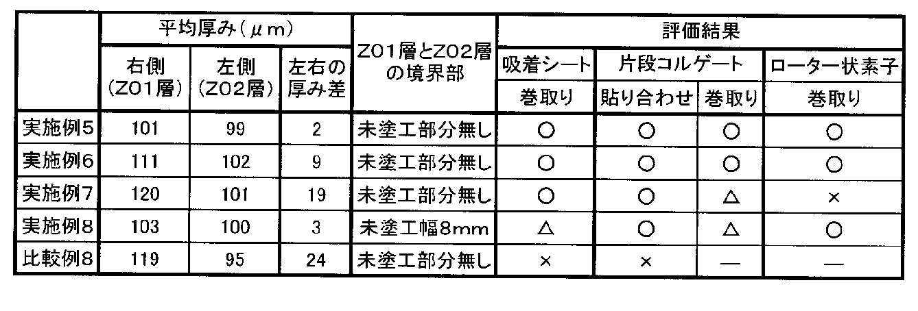
表2より、実施例5及び実施例6の吸着シートは、ローター状の素子とするまでの何れの工程においても、欠陥を生じることなく加工することが可能であることがわかる。また、実施例7の吸着シートは、片段コルゲートシートまでであれば加工することができた。実施例8の吸着シートは、吸着シートの巻取りの際、未塗工部に弛みシワが発生したものの、片段コルゲートシート及びローター状素子への加工は可能であった。しかしながら、比較例8の吸着シートは、吸着シートの巻き取りですら困難であった。
この結果から、吸着シートの加工のために、MD中心線の右側と左側で平均厚みの差が20μm以下であることが必要とされ、更に、ローター状素子までの加工が必要な場合は、厚み差を10μm以下とすることが好ましいことが分かる。
この結果から、吸着シートの加工のために、MD中心線の右側と左側で平均厚みの差が20μm以下であることが必要とされ、更に、ローター状素子までの加工が必要な場合は、厚み差を10μm以下とすることが好ましいことが分かる。
〔吸着材層の厚みと耐屈曲性〕
[実施例9]
実施例1と同様のスラリーと基材を用い、同様の手順で、Z01層とZ02層の帯幅比(面積比)が1:1のストライプ状で、各吸着材層の厚みが100±3μmの吸着シートを作製した。得られた吸着シートを用いて、吸着材層を外側にし、MD方向(縦方向)に周回するようにして、前記と同様に、JIS-K5600-5-1に準拠した円筒形マンドレル法による屈曲試験を行い、欠陥なく屈曲できる最小のマンドレル径を求めた。結果を表3に示す。
[実施例9]
実施例1と同様のスラリーと基材を用い、同様の手順で、Z01層とZ02層の帯幅比(面積比)が1:1のストライプ状で、各吸着材層の厚みが100±3μmの吸着シートを作製した。得られた吸着シートを用いて、吸着材層を外側にし、MD方向(縦方向)に周回するようにして、前記と同様に、JIS-K5600-5-1に準拠した円筒形マンドレル法による屈曲試験を行い、欠陥なく屈曲できる最小のマンドレル径を求めた。結果を表3に示す。
[実施例10]
実施例9と同様の方法で、吸着材層の厚みが200±5μmの吸着シートを得、得られた吸着シートについて、実施例9と同様に屈曲試験を行い、結果を表3に示した。
実施例9と同様の方法で、吸着材層の厚みが200±5μmの吸着シートを得、得られた吸着シートについて、実施例9と同様に屈曲試験を行い、結果を表3に示した。
[実施例11]
実施例9と同様の方法で、吸着材層の厚みが300±5μmの吸着シートを得、得られた吸着シートについて、実施例9と同様に屈曲試験を行い、結果を表3に示した。
実施例9と同様の方法で、吸着材層の厚みが300±5μmの吸着シートを得、得られた吸着シートについて、実施例9と同様に屈曲試験を行い、結果を表3に示した。
[参考例1]
実施例9と同様の方法で、吸着材層の厚みが400±8μmの吸着シートを得、得られた吸着シートについて、実施例9と同様に屈曲試験を行い、結果を表3に示した。
実施例9と同様の方法で、吸着材層の厚みが400±8μmの吸着シートを得、得られた吸着シートについて、実施例9と同様に屈曲試験を行い、結果を表3に示した。
[実施例12]
実施例2と同様のスラリーと基材を用い、同様の手順で、シリカゲル・活性アルミナ混合層と、Z01層と、Z02層の帯幅比(面積比)が1:1:1のストライプ状で、各吸着材層の厚みが100±3μmの吸着シートを作製した。得られた吸着シートについて、実施例9と同様に屈曲試験を行い、結果を表3に示した。
実施例2と同様のスラリーと基材を用い、同様の手順で、シリカゲル・活性アルミナ混合層と、Z01層と、Z02層の帯幅比(面積比)が1:1:1のストライプ状で、各吸着材層の厚みが100±3μmの吸着シートを作製した。得られた吸着シートについて、実施例9と同様に屈曲試験を行い、結果を表3に示した。
[実施例13]
実施例12と同様の方法で、吸着材層の厚みが200±5μmの吸着シートを得、得られた吸着シートについて、実施例9と同様に屈曲試験を行い、結果を表3に示した。
実施例12と同様の方法で、吸着材層の厚みが200±5μmの吸着シートを得、得られた吸着シートについて、実施例9と同様に屈曲試験を行い、結果を表3に示した。
[実施例14]
実施例12と同様の方法で、吸着材層の厚みが300±5μmの吸着シートを得、得られた吸着シートについて、実施例9と同様に屈曲試験を行い、結果を表3に示した。
実施例12と同様の方法で、吸着材層の厚みが300±5μmの吸着シートを得、得られた吸着シートについて、実施例9と同様に屈曲試験を行い、結果を表3に示した。
[参考例2]
実施例12と同様の方法で、吸着材層の厚みが400±8μmの吸着シートを得、得られた吸着シートについて、実施例9と同様に屈曲試験を行い、結果を表3に示した。
実施例12と同様の方法で、吸着材層の厚みが400±8μmの吸着シートを得、得られた吸着シートについて、実施例9と同様に屈曲試験を行い、結果を表3に示した。
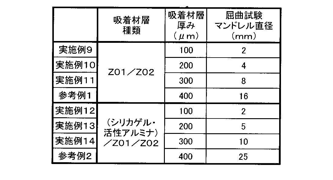
コルゲート加工された吸着素子の場合、マンドレル直径が10mm以下の屈曲性が必要となる場合が多いが、この場合は、吸着材層の厚みは300μm以下であることが好ましいことが、表3の結果から分かる。
本発明を特定の態様を用いて詳細に説明したが、本発明の意図と範囲を離れることなく様々な変更が可能であることは当業者に明らかである。
なお、本出願は、2011年10月24日付で出願された日本特許出願(特願2011-232925)に基づいており、その全体が引用により援用される。
なお、本出願は、2011年10月24日付で出願された日本特許出願(特願2011-232925)に基づいており、その全体が引用により援用される。
Claims (12)
- 基材上に、含有される吸着材の平均細孔径が互いに異なる2種以上の吸着材層を有する吸着シートであって、下記(I)~(V)を満足することを特徴とする吸着シート。
(I)該2種以上の吸着材層は、有機バインダーと吸着材とを含み、該吸着材層中の該有機バインダーの含有量が10重量%以上である。
(II)該2種以上の吸着材層は、該基材の同一面上にストライプ状に設けられている。
(III)該2種以上の吸着材層は、該吸着シートのMD方向に沿う中心線に対して、非対称に設けられている。
(IV)該吸着シートは、25℃の水蒸気吸着等温線において、相対蒸気圧が0.01~0.95の範囲で、相対蒸気圧が0.15変化したときの飽和吸着量の変化量が最大である相対蒸気圧の範囲が、前記中心線の右側と左側で0.05以上異なっている。
(V)該吸着シートは、前記中心線の右側と左側で、平均厚みの差が20μm以下である。 - 該吸着材層の厚みは300μm以下であり、かつJIS-K5600-5-1に準拠した円筒形マンドレル法による耐屈曲試験において、マンドレル径10mmでクラック及び剥がれがみられない請求項1に記載の吸着シート。
- 隣接する2種以上の吸着材層の境界部に未塗工部分が無い請求項1又は2に記載の吸着シート。
- 該2種以上の吸着材層が、該基材の両面にそれぞれ設けられている請求項1ないし3の何れかに記載の吸着シート。
- 該基材が、空気中、300℃で30分間の熱処理をしたときの重量減少率が1重量%以下である熱可塑性樹脂、又は金属よりなることを特徴とする請求項1ないし4の何れかに記載の吸着シート。
- ナイフコーターの液ダムを、1個以上のセパレーターで仕切り、それぞれ吸着材と有機バインダーを含む2種以上の吸着材層形成用塗布液を別個に収容できる部分を設けてなるナイフコーターを用い、該2種以上の塗布液をストライプ状に同時に塗布する工程を含むこと特徴とする請求項1ないし5の何れかに記載の吸着シートの製造方法。
- 該ナイフコーターが、ロールナイフコーターである請求項6に記載の吸着シートの製造方法。
- 請求項1ないし5の何れかに記載の吸着シートを原シートとする吸着素子であって、被処理流体を、前記中心線の右側と左側のうち、前記相対蒸気圧が0.15変化したときの飽和吸着量の変化量が最大となる相対蒸気圧の範囲が高い側から低い側へ流して吸着を行い、再生用媒体を該被処理流体の流通方向と反対の方向に流して脱着を行うことを特徴とする吸着素子。
- 請求項1ないし5の何れかに記載の吸着シートをコルゲート加工してなる吸着素子。
- 請求項1ないし5の何れかに記載の吸着シートをコルゲート加工したものを複数枚積層してハニカム状にしてなる吸着素子。
- 請求項1ないし5の何れかに記載の吸着シートをコルゲート加工したものを巻回してハニカム状のローターにしてなる吸着素子。
- 請求項9ないし11の何れかに記載の吸着素子を用いたデシカント空調装置。
Applications Claiming Priority (2)
| Application Number | Priority Date | Filing Date | Title |
|---|---|---|---|
| JP2011-232925 | 2011-10-24 | ||
| JP2011232925 | 2011-10-24 |
Publications (1)
| Publication Number | Publication Date |
|---|---|
| WO2013061746A1 true WO2013061746A1 (ja) | 2013-05-02 |
Family
ID=48167581
Family Applications (1)
| Application Number | Title | Priority Date | Filing Date |
|---|---|---|---|
| PCT/JP2012/075750 Ceased WO2013061746A1 (ja) | 2011-10-24 | 2012-10-04 | 吸着シート及びその製造方法とその利用 |
Country Status (2)
| Country | Link |
|---|---|
| JP (1) | JP2013107073A (ja) |
| WO (1) | WO2013061746A1 (ja) |
Cited By (4)
| Publication number | Priority date | Publication date | Assignee | Title |
|---|---|---|---|---|
| WO2016121798A1 (ja) * | 2015-01-27 | 2016-08-04 | 日立化成株式会社 | エアロゲル積層体の製造方法及びエアロゲル積層ロール |
| US10267543B2 (en) | 2017-02-07 | 2019-04-23 | Panasonic Intellectual Property Management Co., Ltd. | Adsorption refrigerator, method for controlling adsorption refrigerator, and cooling system |
| CN118454402A (zh) * | 2024-04-26 | 2024-08-09 | 宏芯气体(上海)有限公司 | 一种高纯氮生产的吸附装置 |
| WO2026081347A1 (zh) * | 2024-10-16 | 2026-04-23 | 宁德时代新能源科技股份有限公司 | 除湿转轮和转轮除湿设备 |
Families Citing this family (4)
| Publication number | Priority date | Publication date | Assignee | Title |
|---|---|---|---|---|
| JP6543209B2 (ja) * | 2016-03-24 | 2019-07-10 | パナソニックホームズ株式会社 | 調湿材及び調湿システム |
| SE546393C2 (en) * | 2021-04-27 | 2024-10-22 | Munters Europe Ab | An air treatment element, an air treatment unit and a method for producing the air treatment element |
| CN118767893B (zh) * | 2024-07-19 | 2025-03-04 | 广东锦轮高新材料有限责任公司 | 一种气体湿度控制复合蜂窝体材料及其制备方法 |
| WO2026083445A1 (en) * | 2024-10-16 | 2026-04-23 | Desiccant Rotors International Pvt. Ltd. | Desiccant wheel deploying special materials |
Citations (4)
| Publication number | Priority date | Publication date | Assignee | Title |
|---|---|---|---|---|
| JP2000257912A (ja) * | 1999-03-05 | 2000-09-22 | Daikin Ind Ltd | 吸着体及び空気調和装置 |
| JP2002001106A (ja) * | 2000-06-20 | 2002-01-08 | Ebara Corp | 除湿又は熱交換用機能素子とその製造方法 |
| JP2007167838A (ja) * | 2005-11-24 | 2007-07-05 | Nichias Corp | 除湿ロータ及びその製造方法 |
| JP2010094609A (ja) * | 2008-10-16 | 2010-04-30 | Mitsubishi Chemicals Corp | 吸着材モジュール及び除加湿装置 |
-
2012
- 2012-10-04 JP JP2012222122A patent/JP2013107073A/ja active Pending
- 2012-10-04 WO PCT/JP2012/075750 patent/WO2013061746A1/ja not_active Ceased
Patent Citations (4)
| Publication number | Priority date | Publication date | Assignee | Title |
|---|---|---|---|---|
| JP2000257912A (ja) * | 1999-03-05 | 2000-09-22 | Daikin Ind Ltd | 吸着体及び空気調和装置 |
| JP2002001106A (ja) * | 2000-06-20 | 2002-01-08 | Ebara Corp | 除湿又は熱交換用機能素子とその製造方法 |
| JP2007167838A (ja) * | 2005-11-24 | 2007-07-05 | Nichias Corp | 除湿ロータ及びその製造方法 |
| JP2010094609A (ja) * | 2008-10-16 | 2010-04-30 | Mitsubishi Chemicals Corp | 吸着材モジュール及び除加湿装置 |
Cited By (8)
| Publication number | Priority date | Publication date | Assignee | Title |
|---|---|---|---|---|
| WO2016121798A1 (ja) * | 2015-01-27 | 2016-08-04 | 日立化成株式会社 | エアロゲル積層体の製造方法及びエアロゲル積層ロール |
| CN107206760A (zh) * | 2015-01-27 | 2017-09-26 | 日立化成株式会社 | 气凝胶层叠体的制造方法和气凝胶层叠卷 |
| JPWO2016121798A1 (ja) * | 2015-01-27 | 2017-10-05 | 日立化成株式会社 | エアロゲル積層体の製造方法及びエアロゲル積層ロール |
| US10556405B2 (en) | 2015-01-27 | 2020-02-11 | Hitachi Chemical Company, Ltd. | Production method for aerogel laminate, and aerogel laminate roll |
| US11117353B2 (en) | 2015-01-27 | 2021-09-14 | Showa Denko Materials Co., Ltd. | Production method for aerogel laminate, and aerogel laminate roll |
| US10267543B2 (en) | 2017-02-07 | 2019-04-23 | Panasonic Intellectual Property Management Co., Ltd. | Adsorption refrigerator, method for controlling adsorption refrigerator, and cooling system |
| CN118454402A (zh) * | 2024-04-26 | 2024-08-09 | 宏芯气体(上海)有限公司 | 一种高纯氮生产的吸附装置 |
| WO2026081347A1 (zh) * | 2024-10-16 | 2026-04-23 | 宁德时代新能源科技股份有限公司 | 除湿转轮和转轮除湿设备 |
Also Published As
| Publication number | Publication date |
|---|---|
| JP2013107073A (ja) | 2013-06-06 |
Similar Documents
| Publication | Publication Date | Title |
|---|---|---|
| WO2013061746A1 (ja) | 吸着シート及びその製造方法とその利用 | |
| US5401706A (en) | Desiccant-coated substrate and method of manufacture | |
| CN1327948C (zh) | 吸附涂层组合物,及含有该组合物的层压材料和吸附器组件及制造它们的方法及应用 | |
| JP5744193B2 (ja) | 吸着式熱交換器および温度制御吸着器のためのゼオライト含有ウォッシュコート | |
| US20140262125A1 (en) | Energy exchange assembly with microporous membrane | |
| CN104081148B (zh) | 热交换基体 | |
| US7615194B2 (en) | Purification composition and filter for ozone-containing exhaust gas | |
| KR101359698B1 (ko) | 흡착제가 코팅된 알루미늄 스트립 | |
| WO2010101110A1 (ja) | 水分吸着剤、除湿用シート状物及び除湿用フィルター材 | |
| JP2009106799A (ja) | 吸着シート及びその製造方法ならびに吸着素子 | |
| US20080023181A1 (en) | Adsorption heat exchanger | |
| JP2014018722A (ja) | 除湿用フィルター素子 | |
| JP2013202504A (ja) | ハニカム状吸着素子、その使用方法及びデシカント空調装置 | |
| JP3874187B2 (ja) | 除湿エレメントおよび除湿装置 | |
| JP2010196993A (ja) | デシカント空調装置およびその運転方法 | |
| JP2006175300A (ja) | シート状積層体およびその製造方法ならびに吸着素子 | |
| CN101960248A (zh) | 热交换元件及使用它的空气调节器或加热冷却装置 | |
| JP2010240554A (ja) | 吸放湿性シート、吸放湿性構造体およびそれらの製造方法 | |
| JP4635751B2 (ja) | 吸着エレメントの製造方法 | |
| JP6352915B2 (ja) | 吸放湿性膜を備えたデバイス及び吸放湿性膜を備えたデバイスを備えた水蒸気分離器及び熱交換器 | |
| WO2019045057A1 (ja) | 全熱交換素子用シート、全熱交換素子、全熱交換器、及び水蒸気分離体 | |
| CN222123368U (zh) | 除湿空气处理单元及加热通风空调和制冷系统 | |
| JP4239084B2 (ja) | 吸着エレメント | |
| JP4622660B2 (ja) | 吸着素子 | |
| JP2005177673A (ja) | 吸着エレメント |
Legal Events
| Date | Code | Title | Description |
|---|---|---|---|
| 121 | Ep: the epo has been informed by wipo that ep was designated in this application |
Ref document number: 12844249 Country of ref document: EP Kind code of ref document: A1 |
|
| NENP | Non-entry into the national phase |
Ref country code: DE |
|
| 122 | Ep: pct application non-entry in european phase |
Ref document number: 12844249 Country of ref document: EP Kind code of ref document: A1 |