WO2013061634A1 - ガラス基材への成膜方法 - Google Patents
ガラス基材への成膜方法 Download PDFInfo
- Publication number
- WO2013061634A1 WO2013061634A1 PCT/JP2012/058865 JP2012058865W WO2013061634A1 WO 2013061634 A1 WO2013061634 A1 WO 2013061634A1 JP 2012058865 W JP2012058865 W JP 2012058865W WO 2013061634 A1 WO2013061634 A1 WO 2013061634A1
- Authority
- WO
- WIPO (PCT)
- Prior art keywords
- film
- glass substrate
- heating temperature
- substrate
- film forming
- Prior art date
- Legal status (The legal status is an assumption and is not a legal conclusion. Google has not performed a legal analysis and makes no representation as to the accuracy of the status listed.)
- Ceased
Links
Images




Classifications
-
- C—CHEMISTRY; METALLURGY
- C03—GLASS; MINERAL OR SLAG WOOL
- C03C—CHEMICAL COMPOSITION OF GLASSES, GLAZES OR VITREOUS ENAMELS; SURFACE TREATMENT OF GLASS; SURFACE TREATMENT OF FIBRES OR FILAMENTS MADE FROM GLASS, MINERALS OR SLAGS; JOINING GLASS TO GLASS OR OTHER MATERIALS
- C03C17/00—Surface treatment of glass, not in the form of fibres or filaments, by coating
- C03C17/34—Surface treatment of glass, not in the form of fibres or filaments, by coating with at least two coatings having different compositions
- C03C17/3411—Surface treatment of glass, not in the form of fibres or filaments, by coating with at least two coatings having different compositions with at least two coatings of inorganic materials
- C03C17/3417—Surface treatment of glass, not in the form of fibres or filaments, by coating with at least two coatings having different compositions with at least two coatings of inorganic materials all coatings being oxide coatings
-
- C—CHEMISTRY; METALLURGY
- C03—GLASS; MINERAL OR SLAG WOOL
- C03C—CHEMICAL COMPOSITION OF GLASSES, GLAZES OR VITREOUS ENAMELS; SURFACE TREATMENT OF GLASS; SURFACE TREATMENT OF FIBRES OR FILAMENTS MADE FROM GLASS, MINERALS OR SLAGS; JOINING GLASS TO GLASS OR OTHER MATERIALS
- C03C2218/00—Methods for coating glass
- C03C2218/10—Deposition methods
- C03C2218/15—Deposition methods from the vapour phase
- C03C2218/152—Deposition methods from the vapour phase by cvd
- C03C2218/1525—Deposition methods from the vapour phase by cvd by atmospheric CVD
Definitions
- the present invention relates to a film forming method on a glass substrate.
- Transparent conductive films are widely used in the fields of semiconductors, displays and solar cells.
- the transparent conductive film those made of metal oxides such as STO (strontium titanate) and ITO (Sn-doped indium oxide) are mainly used.
- the transparent conductive film is generally formed using a sputtering method, a vapor deposition method, a metal organic chemical vapor deposition method using an organic metal compound, or the like.
- the mist method is a method of forming a film by atomizing a solution containing a raw material metal as a solute and spraying it on a substrate.
- a film can be formed at atmospheric pressure, so that no manufacturing equipment such as a vacuum vessel and pumps is required.
- a dangerous substance such as an organometallic compound is not used in the mist method, an inexpensive film forming apparatus with a simple configuration can be used.
- Patent Document 1 JP-A-2007-77433 is a prior document disclosing a film forming apparatus for forming a thin film on an object to be processed by spray pyrolysis.
- the raw material solution is sprayed from the discharge means toward the pretreatment chamber for heating the object to be processed to a predetermined temperature and the object to be processed that is maintained at the predetermined temperature.
- a film forming chamber for forming a thin film on the object to be processed and a post-processing chamber for cooling the object to be processed on which the thin film is formed to a predetermined temperature are provided.
- the glass substrate When a thin film is formed on a glass substrate by the mist method or spray pyrolysis method, the glass substrate may be cracked or warped due to internal strain due to the thermal history of heating and cooling. When the glass substrate is cracked or warped, the film properties of the thin film formed on the glass substrate are deteriorated. In a thin film solar cell, the power generation efficiency of the solar cell decreases when the film properties of the thin film decrease.
- the present invention has been made in view of the above problems, and provides a method for forming a film on a glass substrate, which can form a high-quality film while suppressing the occurrence of cracking and warping of the glass substrate. For the purpose.
- the method for forming a film on a glass substrate according to the present invention comprises spraying an aqueous solution containing an oxide precursor as a solute onto a glass substrate at a first heating temperature of 300 ° C. or higher and lower than the strain point of glass.
- a second layer film is formed by spraying an aqueous solution containing an oxide precursor as a solute on a glass substrate under a first film forming step for forming a layer film and a second heating temperature higher than the first heating temperature.
- a second film forming step of forming includes a strain removing step for holding the glass substrate at a temperature equal to or higher than the annealing point of the glass after the second film forming step, and a glass substrate at room temperature after the strain removing step. And a slow cooling step of slowly cooling to a low temperature.
- the second heating temperature is lower than the strain point of the glass. In one form of this invention, the 2nd heating temperature is more than the annealing point of glass.
- the glass substrate is cooled so that the temperature of the glass substrate decreases at a rate of 5 ° C./min to 30 ° C./min.
- the first layer film is a barrier layer that suppresses migration of alkali metal ions from the glass substrate
- the second layer film is a transparent conductive film
- the first layer film is made of Al 2 O 3 , the first heating temperature is 350 ° C. or higher and lower than 480 ° C., and the second layer film is SnO doped with fluorine. 2 and the second heating temperature is not less than 550 ° C. and not more than 600 ° C.
- the method for forming a film on a glass substrate further includes a third film forming step between the second film forming step and the strain removing step.
- a third film forming step an aqueous solution containing the oxide precursor as a solute is sprayed on the glass substrate at a third heating temperature higher than the second heating temperature to form a third layer film.
- the first film is a prism layer
- the second film is a barrier layer that suppresses migration of alkali metal ions from the glass substrate
- the third film is a transparent conductive film.
- the first layer film is made of TiO 2
- the first heating temperature is 300 ° C. or higher and lower than 400 ° C.
- the second layer film is made of Al 2 O 3 or MgO.
- the second heating temperature is 350 ° C. or higher and lower than 480 ° C.
- the third layer film is made of SnO 2 doped with fluorine
- the third heating temperature is 550 ° C. or higher and 600 ° C. or lower.
- the present invention it is possible to form a high-quality film on the glass substrate while suppressing the occurrence of cracking and warping of the glass substrate.
- the film forming apparatus used for the film forming method on the glass substrate according to the first embodiment of the present invention will be described.
- the same or corresponding parts in the drawings are denoted by the same reference numerals, and the description thereof will not be repeated.
- film formation of a transparent conductive film used for a thin film solar cell will be described as an example, but the present invention can be applied to film formation of various films on a glass substrate.
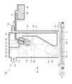
- FIG. 1 is a side view showing a configuration of a film forming apparatus used in a film forming method on a glass substrate according to Embodiment 1 of the present invention.
- FIG. 2 is a cross-sectional view showing a configuration of a film forming chamber included in the film forming apparatus according to the present embodiment.
- FIG. 3 is a view of the film forming chamber of FIG. 2 as viewed from the direction of arrow III. In FIG. 3, the spray mechanism is illustrated in a simplified manner.
- a film forming apparatus 10 includes an input unit 11 into which a substrate 200 that is a glass base material is input, a preheating unit 12 in which the substrate 200 is preheated, and a substrate 200. It has the film-forming part 13 in which film-forming processing is carried out, the slow cooling part 14 in which the board
- the film forming apparatus 10 includes a transfer conveyor 110 that is a transfer means for transferring the substrate 200 along the transfer path.
- the conveyor 110 is provided across the input unit 11, the preheating unit 12, the film forming unit 13, the slow cooling unit 14, and the takeout unit 15.
- the conveyor 110 includes a conveyor belt 111 on which the substrate 200 is placed, a pulley 112 around which the conveyor belt 111 is wound, a drive shaft 113 that drives the pulley 112, and a motor (not shown) that applies power to the drive shaft 113. It consists of and.
- the conveyor belt 111 is made of heat-resistant metal or resin.
- the substrate 200 is transported in the direction indicated by the arrow 114 by the transport conveyor 110. That is, in the film forming apparatus 10 according to the present embodiment, the transport path of the substrate 200 is linear in plan view.
- the conveyance path is not limited to a straight line, and the conveyance path may be bent in a plan view or may be a curved line.
- the film forming apparatus 10 includes a plurality of film forming chambers 100 (100a, 100b, 100c, 100d) positioned so as to be aligned in the transfer path. Specifically, a film formation chamber 100a, a film formation chamber 100b, a film formation chamber 100c, and a film formation chamber 100d are provided in this order from the upstream side in the transport direction of the substrate 200. In the present embodiment, four film formation chambers 100 (100a, 100b, 100c, and 100d) are provided, but a plurality of film formation chambers 100 may be provided.
- the film formation apparatus 10 is positioned in a tunnel shape along the transfer path so as to connect adjacent film formation chambers among the plurality of film formation chambers 100, and the substrate 200 that sequentially passes through the plurality of film formation chambers 100.
- a heating furnace 120 is provided for surrounding and heating. As shown in FIG. 3, the lower portion of the housing 150 is covered with the heating furnace 120.
- An opening is provided in the upper part of the tunnel-shaped heating furnace 120, and a housing 150 is incorporated in the opening.
- the heating furnace 120 is provided over the four film formation chambers 100 (100a, 100b, 100c, 100d).
- the heating furnace 120 is provided from the upstream side of the film forming chamber 100 a located upstream in the transport direction of the substrate 200 in order to preheat the substrate 200. That is, the heating furnace 120 is provided across the preheating unit 12 and the film forming unit 13.
- the substrate 200 is heated while being transported in the heating furnace 120 by the transport conveyor 110.
- the inside of the heating furnace 120 is maintained at substantially the same temperature for each film forming chamber.
- the film forming chamber 100 is an apparatus for forming a film by depositing a fine film forming material 160 on the substrate 200.
- the film formation chamber 100 includes a housing 150, a spray mechanism for spraying a film forming gas obtained by atomizing a film forming material 160 into the housing 150, and one side wall of the housing 150. And an exhaust port 152 for exhausting the film forming gas.
- connection pipe 310 is connected to the exhaust port 152.
- the other end of the connection pipe 310 is connected to an abatement apparatus 300 that is a gas processing means for detoxifying the exhausted film forming gas.
- the housing 150 has an introduction port 151 into which the carrier gas 170 is introduced.
- the housing 150 also has a partition wall 154 that divides the interior of the housing 150 into three spaces.
- the first space is a spray mechanism arrangement space 158 in which a part of the spray mechanism is arranged.
- the second space is a film forming gas spray space 159 in which the film forming gas is sprayed from the spray mechanism.
- the third space is an exhaust space 153 connected to the exhaust port 152.
- the housing 150 has an open portion that faces the substrate 200 and allows the deposition gas to flow from the deposition gas spray space 159 onto the substrate 200.
- the opening part is formed in the lower part of the housing 150. As shown in FIGS. 1 and 3, the open portion is located in the heating furnace 120. A predetermined gap is provided between the substrate 200 being transported by the transport conveyor 110 and the open portion of the housing 150.
- the spray mechanism includes a tank 140 for storing a solution of the film forming material 160, a passage 141 through which compressed air introduced by a compressor (not shown) and the solution of the film forming material 160 are mixed, and a solution of the film forming material 160. And a spray nozzle 130 for atomizing as a film forming gas. An opening 155 is formed in the housing 150 corresponding to the position of the spray nozzle 130.
- a cooling jacket 131 as a cooling means for cooling the spray nozzle 130 is attached to the end of the spray nozzle 130.
- the cooling jacket 131 is connected to a cooling water supply pipe (not shown), and the cooling water circulates inside the cooling jacket 131.
- the spray mechanism includes a cylindrical rectifying member 132 attached to the tip of the spray nozzle 130.
- the rectifying member 132 has a tapered rectifying unit 134 that is located on the inner surface and rectifies the film forming gas.
- the shape of the rectifying unit 134 is not limited to this, and may have a trumpet shape, for example.
- the rectifying member 132 is attached to the cooling jacket 131 by connecting a connecting member (not shown) connected to a part of the outer surface of the rectifying member 132 to a part of the outer surface of the cooling jacket 131.
- the spray nozzle 130 is a two-fluid spray nozzle that mixes two fluids of a film forming material 160 and compressed air and sprays the mixture in a mist form.
- the mist means a state in which droplets having an average particle size of 0.1 ⁇ m or more and 100 ⁇ m or less are dispersed in a gas.
- the average particle diameter of the mist is a value calculated by the immersion method.
- the spray mechanism is not limited to the spray nozzle 130, and a mist-like film forming gas may be generated using ultrasonic waves.
- the mist-like film forming gas is generated by the ultrasonic vibrator, the average particle diameter of the mist can be made uniform compared to the case where the mist-like film forming gas is generated by the spray nozzle 130. Can be prevented from aggregating before reaching the substrate 200.
- the plurality of spray nozzles 130 are arranged in the casing 150 in a direction orthogonal to the conveyance direction of the substrate 200 so as to face the substrate 200 and be spaced from each other.
- three spray nozzles 130 are arranged, but the number of spray nozzles 130 may be one or more.
- the number of spray nozzles 130 provided is the amount of film forming gas sprayed per unit time necessary to satisfy the desired tact time of the film forming process of the substrate 200, or the film forming necessary for performing the film forming process. It is changed appropriately according to the speed.
- the distance between the upper end and the substrate 200 of the furnace 120 is set to 1 / 4L h.
- a part of the carrier gas 170 introduced from the inlet 151 described later is sent to the spray nozzle 130 in order to cool the spray nozzle 130.
- a cooling fan (not shown) is disposed in the vicinity of the spray nozzle 130.
- the spray nozzle 130 is air-cooled by a cooling fan. Further, the spray nozzle 130 is water cooled by the cooling jacket 131 described above.
- the solution of the film forming material 160 before being sprayed from the spray nozzle 130 is cooled to a temperature equal to or lower than the boiling point. More preferably, the solution of the film forming material 160 is cooled to about room temperature.
- This cooling can suppress the volatilization of the solvent in the solution of the film forming material 160 in the spray nozzle 130, so that the concentration of the solution of the film forming material 160 to be sprayed can be kept constant. Further, solidification of the film forming material 160 due to volatilization of the solvent in the solution of the film forming material 160 in the spray nozzle 130 can be suppressed.
- the film can be formed using the film forming material 160 having a constant concentration, the quality of the film formed on the substrate 200 can be stabilized. Further, the clogging of the spray nozzle 130 due to the solidified film forming material 160 can be suppressed.
- a solution in which a chloride of an inorganic material selected from the group consisting of zinc, tin, indium, cadmium and strontium is dissolved in a solvent can be used.
- a solvent water, methanol, ethanol, butanol and the like can be used.
- an aqueous solution containing zinc acetate, an aqueous solution containing indium tin oxide, an aqueous solution containing tin oxide, or the like can be used.
- the solution of the film forming material 160 is not limited to this, and various solutions can be used.
- the concentration of the film forming material 160 solution is not particularly limited, and is, for example, a concentration of 0.1 mol / L or more and 3 mol / L or less.
- a carrier gas 170 made of, for example, compressed air is introduced into the film forming gas spray space 159 of the housing 150 from the introduction port 151.
- the carrier gas 170 introduced into the film forming gas spray space 159 flows in the direction indicated by the arrow 171.
- the carrier gas 170 for example, nitrogen, oxygen, hydrogen, and a mixed gas thereof can be used.
- the mist film forming gas is sprayed from the spray nozzle 130 into the spray region 162 in the direction indicated by the arrow 161.
- the mist film-forming gas and the carrier gas 170 are mixed with each other in the mixing region 181 to become mixed mist.
- the mixed mist flows in the direction indicated by the arrow 182 and reaches the open portion.
- the mixed mist is sprayed onto the main surface of the substrate 200 from the open portion.
- a region where the mixed mist containing the deposition gas is sprayed onto the substrate 200 is referred to as a spray region X.
- the mixed mist that has reached the spray region X flows along the main surface of the substrate 200. Specifically, the mixed mist flows in a direction indicated by an arrow 183 between a facing surface that is a part of the partition wall 154 and that faces the main surface of the substrate 200, and the main surface of the substrate 200. A region where the mixed mist flows in the direction indicated by the arrow 183 is referred to as a flow channel region Y.
- the mixed mist that has passed through the flow path region Y flows in the direction indicated by the arrow 184 in the exhaust space 153.
- a region where the mixed mist is directed from the main surface of the substrate to the exhaust port 152 is referred to as an exhaust region Z.
- the mixed mist that has passed through the exhaust space 153 and has reached the exhaust port 152 is rendered harmless by the detoxifying device 300 and discharged to the outside as the exhaust gas 180.
- the abatement apparatus 300 is not illustrated.
- the above-mentioned spray area X, flow path area Y, and exhaust area Z constitute an open portion.
- the film forming gas flows from the spray mechanism through the open part toward the exhaust port 152.
- the mixed mist is exhausted at a flow rate that is about 3 to 10 times larger than the carrier gas 170 introduced from the introduction port 151.
- the flow rate of the introduced carrier gas 170 and the exhaust flow rate of the mixed mist are appropriately set.
- a film forming gas flows in the film forming chamber 100a as indicated by an arrow 400.
- the film forming gas flows as indicated by an arrow 410.
- the film forming gas flows as indicated by an arrow 420.
- the film forming gas flows as indicated by an arrow 430.
- the substrate 200 passes through the vicinity of the open portion, whereby the substrate 200 is subjected to the film forming process.
- the transfer conveyor 110 is provided so that the substrate 200 passes through the vicinity of the open part.
- the substrate 200 is transferred by the transfer conveyor 110 so as to sequentially pass through the spray region X, the flow channel region Y, and the exhaust region Z in each of the plurality of film forming chambers 100 (100a, 100b, 100c, 100d). .
- the substrate 200 is formed by depositing fine particles of the film forming material 160 on the main surface while passing through the spray region X, the flow channel region Y, and the exhaust region Z.
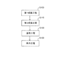
- FIG. 4 is a flowchart showing a film forming method on a glass substrate according to the present embodiment.
- an Al 2 O 3 film is formed as an alkali barrier layer on the substrate 200. Further, a TCO (Transparent Conductive Oxide) film made of SnO 2 doped with fluorine is formed thereon as a transparent conductive film.
- TCO Transparent Conductive Oxide
- the alkali barrier layer is for preventing performance degradation of the solar cell due to the alkali contained in the substrate 200. That is, the alkali barrier layer is a barrier layer that suppresses migration of alkali metal ions from the glass substrate. Therefore, when the substrate 200 is made of a material that does not contain much alkali, the alkali barrier layer need not be formed.
- the annealing point and strain point of the glass constituting the substrate 200 are measured by a beam bending method. Specifically, glass cut and ground into a predetermined shape is measured by a beam bending method (ASTM-C598) using a beam bending measuring apparatus (manufactured by Tokyo Kogyo Co., Ltd.). The slow cooling point of the glass is determined from the deflection rate under cooling. The strain point of glass is calculated.
- the annealing point of the glass is about 543 ° C. to 548 ° C.
- the strain point of the glass is about 498 ° C. to 503 ° C.
- the annealing point of the glass is a temperature at which the internal strain of the glass is substantially removed in 15 minutes, and corresponds to the upper limit temperature in the annealing region, and the viscosity corresponds to 10 13 dPa ⁇ s.
- the strain point of glass is a temperature at which viscous flow of glass cannot practically occur, corresponds to a lower limit temperature in a slow cooling region, and has a viscosity corresponding to 10 14.5 dPa ⁇ s.
- the film formation chamber 100a contains 0.15 mol / L of Al (acac) 3 as an oxide precursor and 20 vol% of CH 3 COOH.
- An aqueous solution is sprayed onto the substrate 200.
- the first heating temperature in the film forming chamber 100a is set to be 300 ° C. or higher and lower than the strain point of glass. In the present embodiment, the first heating temperature is set to 350 ° C. or higher and lower than 480 ° C. More preferably, the 1st heating temperature shall be 420 degreeC or more and less than 480 degreeC.
- An Al 2 O 3 film is formed on the substrate 200 by the first film forming step (S100).
- the oxide precursor SnCl 4 .5H 2 O is 0.9 M
- NH 4 F is 0.3 M
- HCl is 30 vol%
- methanol is 2.
- An aqueous solution containing 5 vol% is sprayed on the substrate 200.
- the second heating temperature in the film forming chamber 100b is set to be higher than the first heating temperature and equal to or higher than the annealing point of the glass. In the present embodiment, the second heating temperature is set to 550 ° C. or more and 600 ° C. or less. More preferably, the second heating temperature is 550 ° C. or higher and 580 ° C. or lower.
- the glass substrate is held at a temperature equal to or higher than the annealing point of the glass as a strain removing step (S120).
- the temperature in the heating furnace 120 located on the downstream side of the film forming chamber 100b is maintained at 550 ° C. or more and 600 ° C. or less. When the temperature exceeds 600 ° C., the burden on the film forming apparatus 10 is increased, which is not preferable.
- the holding time is preferably 5 minutes or more and 30 minutes or less.
- the holding time is shorter than 5 minutes, the internal strain of the substrate 200 due to the thermal history cannot be removed.
- the holding time is longer than 30 minutes, the film formation tact time becomes long and the film formation efficiency decreases.
- the holding time of the strain removing step (S120) can be shortened.
- the film formation tact time can be shortened and the film formation efficiency can be improved.
- the glass substrate is gradually cooled to room temperature as a slow cooling step (S130).
- the slow cooling rate is preferably larger from the viewpoint of downsizing the film forming apparatus 10 and shortening the film forming tact time.
- Air cooling is preferably performed so that the temperature of the substrate 200 decreases at a rate of 5 ° C./min to 30 ° C./min. More preferably, air cooling is performed so that the temperature of the substrate 200 decreases at a rate of 10 ° C./min to 20 ° C./min. Thereby, the internal distortion of the substrate 200 can be prevented from remaining.
- FIG. 5 is a view showing a temperature profile of the substrate in the film forming method on the glass substrate according to the present embodiment.
- the vertical axis represents the substrate temperature
- the horizontal axis represents the substrate transfer position.
- the substrate transfer position indicates the range of the preheating unit 12, the film forming unit 13, and the slow cooling unit 14.
- the substrate 200 is heated while passing through the preheating unit 12, and the temperature is lowered when passing through the spray region X in the film forming chamber 100 a of the film forming unit 13. Thereafter, the temperature of the substrate 200 whose temperature has risen is lowered again when it passes through the spray region X in the film forming chamber 100b of the film forming unit 13. Thereafter, the substrate 200 whose temperature has been further increased is cooled to room temperature while passing through the slow cooling section 14.
- the reason why the temperature of the substrate 200 decreases in the spray region X is that the heat of the substrate 200 is taken away by the heat of vaporization of water, which is a solvent of the sprayed aqueous solution.
- the substrate 200 has a thermal history due to repeated heating and cooling.
- internal strain is accumulated in the substrate 200 due to the thermal history, the substrate 200 is cracked and warped.
- the second heating temperature is set higher than the first heating temperature to suppress accumulation of internal strain of the substrate 200, and the substrate 200 is heated at a temperature equal to or higher than the annealing point of the glass in the strain removing step (S120). And the internal strain of the substrate 200 is removed.
- a high-quality two-layer film can be formed on the substrate 200 while suppressing the occurrence of cracks and warpage in the substrate 200.
- Example 1 As Example 1, an Al 2 O 3 film having a thickness of 40 nm was formed at a first heating temperature of 475 ° C., and an SnO 2 film having a thickness of 900 nm was formed at a second heating temperature of 570 ° C. After maintaining at 560 ° C. for 15 minutes, it was gradually cooled to room temperature.
- a TiO 2 film having a thickness of 10 nm is formed on a glass substrate by sputtering, a SiO 2 film having a thickness of 25 nm is formed thereon, and a SnO film having a thickness of 900 nm is further formed thereon. Two films were formed.
- the transmittance of the TCO film made of the SnO 2 film obtained in Example 1 was 82%, the sheet resistance value was 10 ⁇ / ⁇ , and the haze ratio was 10%. Further, the distribution of Na in Example 1 and the comparative example was measured using a time-of-flight secondary ion mass spectrometer (TOF-SIMS).
- TOF-SIMS time-of-flight secondary ion mass spectrometer
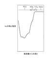
- FIG. 6 is a graph showing the measurement results of Example 1.
- FIG. 7 is a graph showing the measurement results of the comparative example. 6 and 7, the vertical axis represents the Na detection intensity, and the horizontal axis represents the depth from the film surface.
- the detected intensity of Na in the TCO film of Example 1 was lowered in substantially the same manner as the detected Na intensity in the TCO film of the comparative example. That is, the 40 nm thick Al 2 O 3 film formed by the mist method suppresses the migration of alkali metal ions from the glass substrate, almost the same as the 25 nm thick SiO 2 film formed by the sputtering method. Was.
- This experimental example confirmed that a high-quality film can be formed by the film forming method on the glass substrate according to the present embodiment.
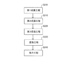
- FIG. 8 is a flowchart showing a film forming method on a glass substrate according to the second embodiment of the present invention.
- a TiO 2 film is formed on the substrate 200 as a prism layer.
- An Al 2 O 3 film or MgO film is formed thereon as an alkali barrier layer.
- a TCO film made of SnO 2 doped with fluorine is formed thereon as a transparent conductive film.
- the first film formation step (S200) an aqueous solution of peroxotitanic acid as an oxide precursor is sprayed onto the substrate 200 in the film formation chamber 100a.
- the first heating temperature is set to be 300 ° C. or higher and lower than 400 ° C.
- a TiO 2 film is formed on the substrate 200 by the first film forming step (S200).
- an aqueous solution containing 0.15 mol / L of Al (acac) 3 as an oxide precursor and 20 vol% of CH 3 COOH is sprayed onto the substrate 200 in the film formation chamber 100b.
- the second heating temperature in the film forming chamber 100b is set to be higher than the first heating temperature and lower than the strain point of the glass.
- the second heating temperature is 350 ° C. or higher and lower than 480 ° C. More preferably, the 2nd heating temperature shall be 420 degreeC or more and less than 480 degreeC.
- An Al 2 O 3 film is formed on the substrate 200 by the second film forming step (S210).
- an MgO film is formed as an alkali barrier layer
- a magnesium chloride aqueous solution as an oxide precursor is sprayed on the substrate 200.
- a 2nd heating temperature shall be 350 degreeC or more and less than 480 degreeC. More preferably, the second heating temperature is set to 430 ° C. or higher and lower than 480 ° C.
- An MgO film is formed on the substrate 200 by the second film forming step.
- the oxide precursor SnCl 4 .5H 2 O is 0.9 M
- NH 4 F is 0.3 M
- HCl is 30 vol%
- methanol is 2.
- An aqueous solution containing 5 vol% is sprayed on the substrate 200.
- the third heating temperature in the film forming chamber 100c is set to be higher than the second heating temperature and equal to or higher than the annealing point of the glass.
- the third heating temperature is set to 550 ° C. or more and 600 ° C. or less. More preferably, the third heating temperature is 550 ° C. or higher and 580 ° C. or lower.
- the distortion removing step (S230) and the slow cooling step (S240) are performed in the same manner as the film forming method on the glass substrate according to the first embodiment.
- the substrate 200 has a thermal history due to repeated heating and cooling.
- internal strain is accumulated in the substrate 200 due to the thermal history, the substrate 200 is cracked and warped.
- the third heating temperature is set higher than the first heating temperature and the second heating temperature to suppress the accumulation of internal strain of the substrate 200, and in the strain removing step (S230), the glass has an annealing temperature higher than the annealing point.
- the substrate 200 is held under temperature to remove the internal strain of the substrate 200. As a result, a high-quality three-layer film can be formed on the substrate 200 while suppressing the occurrence of cracks and warpage in the substrate 200.
- Example 2 As Example 2, a TiO 2 film having a thickness of 20 nm is formed at a first heating temperature of 340 ° C., an Al 2 O 3 film having a thickness of 50 nm is formed at a second heating temperature of 475 ° C., and 3. An SnO 2 film having a thickness of 900 nm was formed at a heating temperature of 570 ° C. After maintaining at 560 ° C. for 15 minutes, it was gradually cooled to room temperature.
- the TiO 2 film obtained in Example 2 shows a high refractive index, the transmittance of the TCO film made of SnO 2 film is 81.5%, the sheet resistance value is 8.4 ⁇ / ⁇ , and the haze ratio is 7.3%. Met.
- a thin film solar cell was produced using the substrate with a TCO film produced in Example 2 and its characteristic value was measured.
- the output of the solar battery cell was 145.7 W
- the open circuit voltage value was 62.2 V
- the short circuit current value was 3.2 A
- the fill factor was 0.731%.
- This experimental example confirmed that a high-quality film can be formed by the film forming method on the glass substrate according to the present embodiment.
- the present invention can also be applied to the case where four or more layers are formed on a glass substrate.
- the heating temperature at the time of film formation is set higher for each layer in order, and the heating temperature at the time of film formation at the end is set to be equal to or higher than the annealing point of the glass, thereby causing the glass substrate to crack and warp. While suppressing, a high quality film can be formed on the glass substrate.
Landscapes
- Chemical & Material Sciences (AREA)
- Life Sciences & Earth Sciences (AREA)
- Engineering & Computer Science (AREA)
- Chemical Kinetics & Catalysis (AREA)
- General Chemical & Material Sciences (AREA)
- Geochemistry & Mineralogy (AREA)
- Materials Engineering (AREA)
- Organic Chemistry (AREA)
- Surface Treatment Of Glass (AREA)
- Chemical Vapour Deposition (AREA)
Abstract
300℃以上かつガラスの歪点より低い第1加熱温度下で、ガラス基材(200)上に酸化物前駆体を溶質として含む水溶液を噴霧して1層目の膜を形成する第1成膜工程(S100)と、第1加熱温度より高い第2加熱温度下で、ガラス基材(200)上に酸化物前駆体を溶質として含む水溶液を噴霧して2層目の膜を形成する第2成膜工程(S110)とを備える。また、第2成膜工程後(S110)に、ガラス基材(200)をガラスの徐冷点以上の温度下で保持する歪取工程(S120)と、歪取工程(S120)後に、ガラス基材(200)を室温まで徐冷する徐冷工程(S130)とを備える。
Description
本発明は、ガラス基材への成膜方法に関する。
半導体、ディスプレイおよび太陽電池などの分野で、透明導電膜が広く利用されている。透明導電膜としては、STO(チタン酸ストロンチウム)およびITO(Snドープ酸化インジウム)などの金属酸化物からなるものが主流である。透明導電膜は、一般的に、スパッタリング法、蒸着法、および、有機金属化合物を用いた有機金属化学気相成長法などを用いて成膜される。
スパッタリング法および蒸着法においては、真空プロセスで成膜するため、真空容器などの真空雰囲気を形成して維持する設備が必要となる。有機金属化学気相成長法においては、原料として用いる有機金属化合物が爆発性および毒性を有するため、機密性の高い設備が必要となる。このため、上記の成膜方法を行なうためには、高価な成膜装置が必要となる。
そこで、従来とは異なる成膜方法としてミスト法が提案されている。ミスト法は、原料金属を溶質として含む溶液を霧化して基板上に噴霧することによって成膜する方法である。
ミスト法においては、大気圧で成膜することができるため、真空容器およびポンプ類などの製造設備が不要である。また、ミスト法においては有機金属化合物のような危険物質を用いないため、簡易な構成で安価な成膜装置を使用することができる。
スプレー熱分解法により被処理体上に薄膜を形成する成膜装置を開示した先行文献として、特開2007-77433号公報(特許文献1)がある。特許文献1に記載された成膜装置においては、被処理体を所定の温度まで加熱する前処理室と、所定の温度に保持した被処理体に向けて、吐出手段から原料溶液を噴霧することにより、被処理体に薄膜を形成する成膜室と、薄膜を形成した被処理体を所定の温度まで冷却する後処理室とを備えている。
ミスト法またはスプレー熱分解法によりガラス基材上に薄膜を形成する際、加熱および冷却の熱履歴による内部歪によりガラス基材に割れまたは反りが発生することがある。ガラス基材に割れまたは反りが発生した場合、ガラス基材上に成膜された薄膜の膜特性が低下する。薄膜太陽電池においては、薄膜の膜特性が低下すると太陽電池の発電効率が低下する。
本発明は上記の問題点に鑑みてなされたものであって、ガラス基材の割れおよび反りの発生を抑制して高品質の膜を成膜できる、ガラス基材への成膜方法を提供することを目的とする。
本発明に基づくガラス基材への成膜方法は、300℃以上かつガラスの歪点より低い第1加熱温度下で、ガラス基材上に酸化物前駆体を溶質として含む水溶液を噴霧して1層目の膜を形成する第1成膜工程と、第1加熱温度より高い第2加熱温度下で、ガラス基材上に酸化物前駆体を溶質として含む水溶液を噴霧して2層目の膜を形成する第2成膜工程とを備える。また、ガラス基材への成膜方法は、第2成膜工程後に、ガラス基材をガラスの徐冷点以上の温度下で保持する歪取工程と、歪取工程後に、ガラス基材を室温まで徐冷する徐冷工程とを備える。
本発明の一形態においては、第2加熱温度がガラスの歪点より低い。
本発明の一形態においては、第2加熱温度がガラスの徐冷点以上である。
本発明の一形態においては、第2加熱温度がガラスの徐冷点以上である。
好ましくは、徐冷工程において、ガラス基材の温度が5℃/分以上30℃/分以下の速度で低下するように冷却する。
本発明の一形態においては、1層目の膜は、ガラス基材からアルカリ金属イオンが移行するのを抑制するバリア層であり、2層目の膜は、透明導電膜である。
本発明の一形態においては、1層目の膜は、Al2O3からなり、第1加熱温度は、350℃以上480℃未満であり、2層目の膜は、フッ素をドープされたSnO2からなり、第2加熱温度は、550℃以上600℃以下である。
本発明の一形態においては、ガラス基材への成膜方法は、第2成膜工程と歪取工程との間に第3成膜工程をさらに備える。第3成膜工程においては、第2加熱温度より高い第3加熱温度下で、ガラス基材上に酸化物前駆体を溶質として含む水溶液を噴霧して3層目の膜を形成する。1層目の膜は、プリズム層であり、2層目の膜は、ガラス基材からアルカリ金属イオンが移行するのを抑制するバリア層であり、3層目の膜は、透明導電膜である。
本発明の一形態においては、1層目の膜は、TiO2からなり、第1加熱温度は、300℃以上400℃未満であり、2層目の膜は、Al2O3またはMgOからなり、第2加熱温度は、350℃以上480℃未満であり、3層目の膜は、フッ素をドープされたSnO2からなり、第3加熱温度は、550℃以上600℃以下である。
本発明によれば、ガラス基材の割れおよび反りの発生を抑制してガラス基材上に高品質の膜を成膜できる。
まず、本発明の実施形態1に係るガラス基材への成膜方法に用いる成膜装置について説明する。以下の実施形態の説明においては、図中の同一または相当部分には同一符号を付して、その説明は繰り返さない。本実施形態においては、薄膜太陽電池などに用いられる透明導電膜の成膜を例に説明するが、本発明はガラス基材上への様々な膜の成膜に応用可能である。
(実施形態1)
図1は、本発明の実施形態1に係るガラス基材への成膜方法に用いる成膜装置の構成を示す側面図である。図2は、本実施形態に係る成膜装置に含まれる成膜室の構成を示す断面図である。図3は、図2の成膜室を矢印III方向から見た図である。なお、図3においては、噴霧機構を簡略に図示している。
図1は、本発明の実施形態1に係るガラス基材への成膜方法に用いる成膜装置の構成を示す側面図である。図2は、本実施形態に係る成膜装置に含まれる成膜室の構成を示す断面図である。図3は、図2の成膜室を矢印III方向から見た図である。なお、図3においては、噴霧機構を簡略に図示している。
図1に示すように、本発明の実施形態に係る成膜装置10は、ガラス基材である基板200が投入される投入部11と、基板200が予熱される予熱部12と、基板200が成膜処理される成膜部13と、基板200が冷却される徐冷部14と、基板200が取り出される取出し部15とを有している。
図1から3に示すように、成膜装置10は、基板200を搬送経路に沿って搬送する搬送手段である搬送コンベア110を備える。搬送コンベア110は、投入部11、予熱部12、成膜部13、徐冷部14および取出し部15に亘って設けられている。
搬送コンベア110は、基板200が載置される搬送ベルト111と、搬送ベルト111が巻き掛けられたプーリ112と、プーリ112を駆動させる駆動軸113と、駆動軸113に動力を付与する図示しないモータとから構成されている。搬送ベルト111は、耐熱性を有する金属または樹脂から形成されている。
基板200は、搬送コンベア110により矢印114で示す方向に搬送される。すなわち、本実施形態に係る成膜装置10においては、基板200の搬送経路は平面視において直線状である。ただし、搬送経路は直線状に限られず、搬送経路が平面視において屈曲していてもよいし、曲線状であってもよい。
また、成膜装置10は、搬送経路中に並ぶように位置する複数の成膜室100(100a,100b,100c,100d)を備える。具体的には、基板200の搬送方向の上流側から順に、成膜室100a、成膜室100b、成膜室100c、成膜室100dが設けられている。本実施形態においては、4つの成膜室100(100a,100b,100c,100d)が設けられているが、複数の成膜室100が設けられていればよい。
さらに、成膜装置10は、複数の成膜室100のうち隣接する成膜室同士を繋ぐように搬送経路に沿ってトンネル状に位置し、複数の成膜室100を順次通過する基板200を取り囲んで加熱する加熱炉120を備える。図3に示すように、筐体150の下部が、加熱炉120に覆われている。
トンネル状の加熱炉120の上部に開口が設けられ、その開口内に筐体150が組み込まれている。加熱炉120は、4つの成膜室100(100a,100b,100c,100d)に亘って設けられている。加熱炉120は、基板200を予熱するために、基板200の搬送方向の上流側に位置する成膜室100aより上流側から設けられている。すなわち、加熱炉120は、予熱部12および成膜部13に亘って設けられている。
基板200は、搬送コンベア110により加熱炉120内を搬送されつつ加熱される。基板200に成膜する際には、加熱炉120内は、成膜室毎にほぼ同一の温度に維持されている。
本実施形態に係る成膜室100は、微粒子化した成膜材料160を基板200上に堆積させて成膜する装置である。図2に示すように、成膜室100は、筐体150と、筐体150の内部に成膜材料160を微粒子化した成膜ガスを噴霧する噴霧機構と、筐体150の1つの側壁に位置して成膜ガスを排気するための排気口152とを有している。
図1に示すように、排気口152には、接続管310の一端が接続されている。接続管310の他端は、排気された成膜ガスを無害化処理するガス処理手段である除害装置300に接続されている。
図2に示すように、筐体150は、キャリアガス170が導入される導入口151を有している。また、筐体150は、筐体150内を3つの空間に分割する仕切壁154を有している。第1の空間は、噴霧機構の一部が配置される噴霧機構配置空間158である。第2の空間は、噴霧機構から成膜ガスが噴霧される成膜ガス噴霧空間159である。第3の空間は、排気口152と繋がっている排気空間153である。
筐体150は、成膜ガス噴霧空間159から成膜ガスを基板200上に流動可能とする、基板200と対向する開放部を有している。開放部は、筐体150の下部に形成されている。図1,3に示すように、開放部は、加熱炉120内に位置している。搬送コンベア110により搬送されている基板200と筐体150の開放部との間には、所定の隙間が設けられている。
噴霧機構は、成膜材料160の溶液を貯留するタンク140と、図示しないコンプレッサーにより導入された圧縮空気と成膜材料160の溶液とが混合されて通過する通路141と、成膜材料160の溶液を微粒子化して成膜ガスとして噴霧するスプレーノズル130とから構成されている。筐体150には、スプレーノズル130の位置に対応して開口155が形成されている。
スプレーノズル130の端部に、スプレーノズル130を冷却する冷却手段である冷却ジャケット131が取り付けられている。冷却ジャケット131は図示しない冷却水供給管と接続され、冷却ジャケット131の内部では冷却水が循環している。
また、噴霧機構は、スプレーノズル130の先端に取り付けられた筒状の整流部材132を含む。本実施形態においては、整流部材132は、内側面に位置して成膜ガスを整流するテーパ状の整流部134を有している。ただし、整流部134の形状はこれに限られず、たとえば、ラッパ状の形状を有していてもよい。
整流部材132は、整流部材132の外側面の一部に接続された図示しない接続部材が冷却ジャケット131の外側面の一部に接続されることにより、冷却ジャケット131に取り付けられている。
スプレーノズル130は、成膜材料160の溶液と圧縮空気との2流体を混合してミスト状に噴霧する2流体スプレーノズルである。ここで、ミストとは、平均粒子経が0.1μm以上100μm以下の液滴が気体中に分散された状態のものをいう。ミストの平均粒子径は、液浸法によって算出された値とする。
ただし、噴霧機構はスプレーノズル130に限られず、超音波を用いてミスト状の成膜ガスを発生させるものでもよい。超音波振動子によってミスト状の成膜ガスを発生させる場合、スプレーノズル130によりミスト状の成膜ガスを発生させる場合に比べて、ミストの平均粒子径を均一にできるため、発生させたミスト同士が基板200に到達する前に凝集することを抑制できる。
図3に示すように、複数のスプレーノズル130は、筐体150内において、基板200と対向して互いに間隔を置いて基板200の搬送方向と直交する方向に並んでいる。図3においては、3つのスプレーノズル130を配置しているが、スプレーノズル130の数は1つ以上であればよい。
設けられるスプレーノズル130の数は、基板200の成膜処理の所望のタクトタイムを満たすために必要な単位時間当たりの成膜ガスの噴霧量、または、成膜処理を行なううえで必要な成膜速度に応じて適宜変更される。
スプレーノズル130の吐出口と基板200の上面との間の距離Lhに対して、加熱炉120の上端と基板200との間の距離は、1/4Lhに設定されている。
なお、後述する導入口151から導入されるキャリアガス170の一部は、スプレーノズル130を冷却するためにスプレーノズル130に対して送られる。スプレーノズル130にキャリアガス170を送るために、スプレーノズル130の近傍に図示しない冷却ファンが配置されている。スプレーノズル130は、冷却ファンにより空冷される。さらに、スプレーノズル130は上述の冷却ジャケット131により水冷される。
このように、スプレーノズル130の近傍を冷却することにより、スプレーノズル130から噴き付けられる前の成膜材料160の溶液が沸点以下の温度まで冷却される。より好ましくは、成膜材料160の溶液が室温程度まで冷却される。
この冷却により、成膜材料160の溶液中の溶媒がスプレーノズル130内において揮発することを抑制できるため、噴き付けられる成膜材料160の溶液の濃度を一定に保つことができる。また、スプレーノズル130内において成膜材料160の溶液中の溶媒が揮発することによる成膜材料160の固化を抑制できる。
その結果、一定の濃度の成膜材料160を用いて成膜できるため、基板200上に成膜される膜の品質を安定させることができる。また、固化した成膜材料160によるスプレーノズル130の目詰まりを抑制することができる。
成膜材料160の溶液としては、亜鉛、スズ、インジウム、カドミウムおよびストロンチウムからなる群より選択される無機材料の塩化物を、溶媒に溶解させた溶液を用いることができる。溶媒としては、水、メタノール、エタノールおよびブタノールなどを用いることができる。このような成膜材料160の溶液としては、たとえば、酢酸亜鉛を含む水溶液、酸化インジウム錫を含む水溶液および酸化錫を含む水溶液などを用いることができる。
ただし、成膜材料160の溶液としてはこれに限られず、種々の溶液を用いることができる。成膜材料160の溶液の濃度は特に限定されないが、たとえば、0.1mol/L以上3mol/L以下の濃度である。
ここで、筐体150内におけるガスの流動経路について説明する。まず、導入口151から、たとえば圧縮空気からなるキャリアガス170が筐体150の成膜ガス噴霧空間159内に導入される。成膜ガス噴霧空間159内に導入されたキャリアガス170は、矢印171で示す向きに流動する。キャリアガス170としては、たとえば、窒素、酸素、水素およびこれらの混合ガスを用いることができる。
スプレーノズル130からミスト状の成膜ガスが、矢印161で示す向きに噴霧領域162中に噴霧される。ミスト状の成膜ガスとキャリアガス170とは、混合領域181において互いに混合されて混合ミストとなる。混合ミストは、矢印182で示す向きに流動して開放部に到達する。混合ミストは、開放部から基板200の主面上に噴き付けられる。成膜ガスを含む混合ミストが基板200上に噴き付けられる領域を、噴き付け領域Xと称する。
噴き付け領域Xに到達した混合ミストは、基板200の主面に沿って流動する。具体的には、仕切壁154の一部であって基板200の主面と対向している対向面と、基板200の主面との間を矢印183で示す向きに混合ミストが流動する。混合ミストが矢印183で示す向きに流動する領域を、流路領域Yと称する。
流路領域Yを通過した混合ミストは、排気空間153内を矢印184で示す向きに流動する。このように混合ミストが基板の主面上から排気口152に向かう領域を、排気領域Zと称する。排気空間153内を通過して排気口152に到達した混合ミストは、除害装置300により無害化されて排気ガス180として外部に放出される。なお、図2においては、除害装置300を図示していない。
上記の噴き付け領域Xと流路領域Yと排気領域Zとから開放部が構成されている。成膜ガスは、複数の成膜室100(100a,100b,100c,100d)の各々において、噴霧機構から開放部を通過して排気口152に向けて流動する。
なお、排気口152においては、導入口151から導入されるキャリアガス170の3倍~10倍程度大きな流量で混合ミストを排気している。ただし、導入されるキャリアガス170の流量および混合ミストの排気流量は適宜設定される。スプレーノズル130の吐出圧力、キャリアガス170の流量および排気流量を適切に設定することにより、混合ミストを安定して基板200の上面に到達させることができる。
図1に示すように、成膜室100aにおいて、矢印400で示すように成膜ガスが流動する。成膜室100bにおいて、矢印410で示すように成膜ガスが流動する。成膜室100cにおいて、矢印420で示すように成膜ガスが流動する。成膜室100dにおいて、矢印430で示すように成膜ガスが流動する。
上記のように成膜ガスが流動している状態で、開放部の近傍を基板200が通過することにより、基板200が成膜処理される。本実施形態の成膜装置10においては、開放部の近傍を基板200が通過するように搬送コンベア110が設けられている。
基板200は、搬送コンベア110により、複数の成膜室100(100a,100b,100c,100d)の各々において、噴き付け領域X、流路領域Yおよび排気領域Zを順に通過するように搬送される。基板200は、噴き付け領域X、流路領域Yおよび排気領域Zを通過する間に、主面上に成膜材料160の微粒子が堆積することにより成膜される。
以下、本実施形態に係るガラス基材への成膜方法について詳細に説明する。図4は、本実施形態に係るガラス基材への成膜方法を示すフローチャートである。
本実施形態においては、基板200上にアルカリバリア層としてAl2O3膜を形成する。さらにその上に、透明導電膜として、フッ素をドープされたSnO2からなるTCO(Transparent Conductive Oxide)膜を形成する。
なお、アルカリバリア層は、基板200に含まれるアルカリ分によって太陽電池の性能低下を防止するためのものである。すなわち、アルカリバリア層は、ガラス基材からアルカリ金属イオンが移行するのを抑制するバリア層である。そのため、基板200がアルカリ分を多く含まない材質からなる場合、アルカリバリア層を形成しなくてもよい。
まず、基板200を構成するガラスの徐冷点および歪点を、ビーム曲げ法により測定する。具体的には、所定の形状に切断および研削したガラスをビーム曲げ測定装置(東京工業株式会社製など)を用いてビーム曲げ法(ASTM-C598)により測定する。ガラスの徐冷点は、降温下でのたわみ速度から求める。ガラスの歪点は計算により算出する。
本実施形態に係るガラス基材におけるガラスの徐冷点は543℃~548℃程度であり、ガラスの歪点は498℃~503℃程度である。なお、ガラスの徐冷点とは、ガラスの内部歪が15分間で実質的に除去される温度で、徐冷域における上限温度に相当し、粘度が1013dPa・sに相当する温度である。ガラスの歪点とは、ガラスの粘性流動が事実上起こりえない温度で、徐冷域における下限温度に相当し、粘度が1014.5dPa・sに相当する温度である。
図4に示すように、第1成膜工程(S100)として、成膜室100aにおいて、酸化物前駆体であるAl(acac)3を0.15mol/L、および、CH3COOHを20vol%含む水溶液を基板200上に噴霧する。成膜室100a内の第1加熱温度は、300℃以上かつガラスの歪点より低くなるように設定される。本実施形態においては、第1加熱温度を350℃以上480℃未満とする。より好ましくは、第1加熱温度を420℃以上480℃未満とする。第1成膜工程(S100)により、基板200上にAl2O3膜が形成される。
第2成膜工程(S110)として、成膜室100bにおいて、酸化物前駆体であるSnCl4・5H2Oを0.9M、NH4Fを0.3M、HClを30vol%、メタノールを2.5vol%含む水溶液を基板200上に噴霧する。成膜室100b内の第2加熱温度は、第1加熱温度より高くかつガラスの徐冷点以上となるように設定される。本実施形態においては、第2加熱温度を550℃以上600℃以下とする。より好ましくは、第2加熱温度を550℃以上580℃以下とする。
第2成膜工程(S110)後に、歪取工程(S120)としてガラス基材をガラスの徐冷点以上の温度下で保持する。本実施形態においては、成膜室100bより下流側に位置する加熱炉120内の温度を550℃以上600℃以下に保持する。温度が600℃を超えると、成膜装置10への負担が大きくなり好ましくない。
保持時間としては、5分以上30分以下であることが好ましい。保持時間が5分より短い場合、熱履歴による基板200の内部歪を除去できない。保持時間が30分より長い場合、成膜タクトタイムが長くなり成膜効率が低下する。
本実施形態においては、第2加熱温度をガラスの徐冷点以上となるように設定しているため、歪取工程(S120)の保持時間を短くすることができる。その結果、成膜タクトタイムを短くして成膜効率を向上できる。
歪取工程(S120)後に、徐冷工程(S130)としてガラス基材を室温まで徐冷する。徐冷速度は、成膜装置10の小型化および成膜タクトタイムの短縮化の観点から大きい方がよい。基板200の温度が5℃/分以上30℃/分以下の速度で低下するように空冷することが好ましい。より好ましくは、基板200の温度が10℃/分以上20℃/分以下の速度で低下するように空冷する。これにより、基板200の内部歪が残らないようにすることができる。
図5は、本実施形態に係るガラス基材への成膜方法における基板の温度プロファイルを示す図である。図5においては、縦軸に基板温度、横軸に基板搬送位置を示している。基板搬送位置は、予熱部12、成膜部13および徐冷部14の範囲を示している。
図5に示すように、基板200は、予熱部12を通過する間に加熱され、成膜部13の成膜室100a内の噴き付け領域Xを通過する際に温度が低下する。その後、昇温した基板200は、成膜部13の成膜室100b内の噴き付け領域Xを通過する際に再び温度が低下する。その後さらに昇温した基板200は、徐冷部14を通過する間に室温まで冷却される。なお、噴き付け領域Xで基板200の温度が低下する理由は、吹き付けられた水溶液の溶媒である水の気化熱により基板200の熱が奪われるためである。
このように、ミスト法を用いて2層の膜を成膜する場合、基板200は加熱および冷却の繰り返しによる熱履歴を有することになる。この熱履歴により基板200に内部歪が蓄積されると、基板200に割れおよび反りなどが発生する。
本実施形態においては、第2加熱温度を第1加熱温度より高くして基板200の内部歪の蓄積を抑制しつつ、歪取工程(S120)においてガラスの徐冷点以上の温度下で基板200を保持して基板200の内部歪を除去している。その結果、基板200に割れおよび反りが発生することを抑制しつつ、基板200上に高品質の2層の膜を成膜することができる。
以下、本実施形態に係るガラス基材への成膜方法により成膜を行なった実験例について説明する。
(実験例1)
実施例1として、第1加熱温度を475℃にして40nmの膜厚のAl2O3膜を形成し、第2加熱温度を570℃にして900nmの膜厚のSnO2膜を形成した。560℃で15分間保持した後、室温まで徐冷した。
実施例1として、第1加熱温度を475℃にして40nmの膜厚のAl2O3膜を形成し、第2加熱温度を570℃にして900nmの膜厚のSnO2膜を形成した。560℃で15分間保持した後、室温まで徐冷した。
比較例として、スパッタリング法により、ガラス基材上に10nmの膜厚のTiO2膜を形成し、その上に25nmの膜厚のSiO2膜を形成し、さらにその上に900nmの膜厚のSnO2膜を形成した。
実施例1で得られたSnO2膜からなるTCO膜の透過率は82%、シート抵抗値は10Ω/□、ヘイズ率は10%であった。また、飛行時間二次イオン質量分析計(TOF-SIMS(Time-of-flight secondary ion mass spectrometer))を用いて、実施例1および比較例のNaの分布を計測した。
図6は、実施例1の計測結果を示すグラフである。図7は、比較例の計測結果を示すグラフである。図6,7においては、縦軸にNaの検出強度、横軸に膜表面からの深さを示している。
図6,7に示すように、実施例1のTCO膜内のNaの検出強度が、比較例のTCO膜内のNa検出強度と略同様に低下していた。すなわち、スパッタリング法により形成した25nmの膜厚のSiO2膜と略同等に、ミスト法により形成した40nmの膜厚のAl2O3膜が、ガラス基材からアルカリ金属イオンが移行するのを抑制していた。
本実験例により、本実施形態に係るガラス基材への成膜方法により高品質の膜が形成できることが確認された。
以下、本発明の実施形態2に係るガラス基材への成膜方法について説明する。なお、本実施形態に係るガラス基材への成膜方法は、第3成膜工程を備える点のみ実施形態1に係るガラス基材への成膜方法と異なるため、他の構成については説明を繰り返さない。
(実施形態2)
図8は、本発明の実施形態2に係るガラス基材への成膜方法を示すフローチャートである。本実施形態においては、基板200上にプリズム層としてTiO2膜を形成する。その上に、アルカリバリア層としてAl2O3膜またはMgO膜を形成する。さらにその上に、透明導電膜として、フッ素をドープされたSnO2からなるTCO膜を形成する。
図8は、本発明の実施形態2に係るガラス基材への成膜方法を示すフローチャートである。本実施形態においては、基板200上にプリズム層としてTiO2膜を形成する。その上に、アルカリバリア層としてAl2O3膜またはMgO膜を形成する。さらにその上に、透明導電膜として、フッ素をドープされたSnO2からなるTCO膜を形成する。
図8に示すように、第1成膜工程(S200)として、成膜室100aにおいて、酸化物前駆体であるペルオキソチタン酸の水溶液を基板200上に噴霧する。本実施形態においては、第1加熱温度を300℃以上400℃未満とする。第1成膜工程(S200)により、基板200上にTiO2膜が形成される。
第2成膜工程(S210)として、成膜室100bにおいて、酸化物前駆体であるAl(acac)3を0.15mol/L、および、CH3COOHを20vol%含む水溶液を基板200上に噴霧する。成膜室100b内の第2加熱温度は、第1加熱温度より高くかつガラスの歪点より低くなるように設定される。本実施形態においては、第2加熱温度を350℃以上480℃未満とする。より好ましくは、第2加熱温度を420℃以上480℃未満とする。第2成膜工程(S210)により、基板200上にAl2O3膜が形成される。
また、アルカリバリア層としてMgO膜を形成する場合には、酸化物前駆体である塩化マグネシウム水溶液を基板200上に噴霧する。第2加熱温度を350℃以上480℃未満とする。より好ましくは、第2加熱温度を430℃以上480℃未満とする。第2成膜工程により、基板200上にMgO膜が形成される。
第3成膜工程(S220)として、成膜室100cにおいて、酸化物前駆体であるSnCl4・5H2Oを0.9M、NH4Fを0.3M、HClを30vol%、メタノールを2.5vol%含む水溶液を基板200上に噴霧する。成膜室100c内の第3加熱温度は、第2加熱温度より高くかつガラスの徐冷点以上となるように設定される。本実施形態においては、第3加熱温度を550℃以上600℃以下とする。より好ましくは、第3加熱温度を550℃以上580℃以下とする。
歪取工程(S230)および徐冷工程(S240)は、実施形態1に係るガラス基材への成膜方法と同様に行なう。このように、ミスト法を用いて3層の膜を成膜する場合、基板200は加熱および冷却の繰り返しによる熱履歴を有することになる。この熱履歴により基板200に内部歪が蓄積されると、基板200に割れおよび反りなどが発生する。
本実施形態においては、第3加熱温度を第1加熱温度および第2加熱温度より高くして基板200の内部歪の蓄積を抑制しつつ、歪取工程(S230)においてガラスの徐冷点以上の温度下で基板200を保持して基板200の内部歪を除去している。その結果、基板200に割れおよび反りが発生することを抑制しつつ、基板200上に高品質の3層の膜を成膜することができる。
以下、本実施形態に係るガラス基材への成膜方法により成膜を行なった実験例について説明する。
(実験例2)
実施例2として、第1加熱温度を340℃にして20nmの膜厚のTiO2膜を形成し、第2加熱温度を475℃にして50nmの膜厚のAl2O3膜を形成し、第3加熱温度を570℃にして900nmの膜厚のSnO2膜を形成した。560℃で15分間保持した後、室温まで徐冷した。
実施例2として、第1加熱温度を340℃にして20nmの膜厚のTiO2膜を形成し、第2加熱温度を475℃にして50nmの膜厚のAl2O3膜を形成し、第3加熱温度を570℃にして900nmの膜厚のSnO2膜を形成した。560℃で15分間保持した後、室温まで徐冷した。
実施例2で得られたTiO2膜は高い屈折率を示し、SnO2膜からなるTCO膜の透過率は81.5%、シート抵抗値は8.4Ω/□、ヘイズ率は7.3%であった。
また、実施例2で作製されたTCO膜付基板を用いて薄膜太陽電池を作製してその特性値を測定した。その結果、太陽電池セルの出力が145.7W、開放電圧値が62.2V、短絡電流値が3.2A、フィルファクタが0.731%であった。
本実験例により、本実施形態に係るガラス基材への成膜方法により高品質の膜が形成できることが確認された。
なお、本発明は、ガラス基材上に4層以上の膜を成膜する場合にも適用可能である。この場合、成膜する際の加熱温度を1層毎順に高く設定し、最後に成膜する際の加熱温度をガラスの徐冷点以上にすることにより、ガラス基材の割れおよび反りの発生を抑制しつつ、ガラス基材上に高品質の膜を成膜することができる。
今回開示された実施形態はすべての点で例示であって制限的なものではないと考えられるべきである。本発明の範囲は上記した説明ではなくて請求の範囲によって示され、請求の範囲と均等の意味および範囲内でのすべての変更が含まれることが意図される。
10 成膜装置、11 投入部、12 予熱部、13 成膜部、14 徐冷部、15 取出し部、100,100a,100b,100c,100d 成膜室、110 搬送コンベア、111 搬送ベルト、112 プーリ、113 駆動軸、120 加熱炉、130 スプレーノズル、131 冷却ジャケット、132 整流部材、134 整流部、140 タンク、141 通路、150 筐体、151 導入口、152 排気口、153 排気空間、154 仕切壁、155 開口、158 噴霧機構配置空間、159 成膜ガス噴霧空間、160 成膜材料、162 噴霧領域、170 キャリアガス、180 排気ガス、181 混合領域、200 基板、300 除害装置、310 接続管、X 噴き付け領域、Y 流路領域、Z 排気領域。
Claims (8)
- 300℃以上かつガラスの歪点より低い第1加熱温度下で、ガラス基材(200)上に酸化物前駆体を溶質として含む水溶液を噴霧して1層目の膜を形成する第1成膜工程(S100,S200)と、
前記第1加熱温度より高い第2加熱温度下で、前記ガラス基材(200)上に酸化物前駆体を溶質として含む水溶液を噴霧して2層目の膜を形成する第2成膜工程(S110,S210)と、
前記第2成膜工程後に、前記ガラス基材(200)をガラスの徐冷点以上の温度下で保持する歪取工程(S120,S230)と、
前記歪取工程後に、前記ガラス基材(200)を室温まで徐冷する徐冷工程(S130,S240)と
を備える、ガラス基材への成膜方法。 - 前記第2加熱温度が前記ガラスの歪点より低い、請求項1に記載のガラス基材への成膜方法。
- 前記第2加熱温度が前記ガラスの徐冷点以上である、請求項1に記載のガラス基材への成膜方法。
- 前記徐冷工程(S130,S240)において、前記ガラス基材(200)の温度が5℃/分以上30℃/分以下の速度で低下するように冷却する、請求項1に記載のガラス基材への成膜方法。
- 前記1層目の膜は、前記ガラス基材(200)からアルカリ金属イオンが移行するのを抑制するバリア層であり、
前記2層目の膜は、透明導電膜である、請求項1に記載のガラス基材への成膜方法。 - 前記1層目の膜は、Al2O3からなり、
前記第1加熱温度は、350℃以上480℃未満であり、
前記2層目の膜は、フッ素をドープされたSnO2からなり、
前記第2加熱温度は、550℃以上600℃以下である、請求項5に記載のガラス基材への成膜方法。 - 前記第2成膜工程(S210)と前記歪取工程(S230)との間に第3成膜工程(S220)をさらに備え、
前記第3成膜工程(S220)においては、前記第2加熱温度より高い第3加熱温度下で、前記ガラス基材(200)上に酸化物前駆体を溶質として含む水溶液を噴霧して3層目の膜を形成し、
前記1層目の膜は、プリズム層であり、
前記2層目の膜は、前記ガラス基材(200)からアルカリ金属イオンが移行するのを抑制するバリア層であり、
前記3層目の膜は、透明導電膜である、請求項1に記載のガラス基材への成膜方法。 - 前記1層目の膜は、TiO2からなり、
前記第1加熱温度は、300℃以上400℃未満であり、
前記2層目の膜は、Al2O3またはMgOからなり、
前記第2加熱温度は、350℃以上480℃未満であり、
前記3層目の膜は、フッ素をドープされたSnO2からなり、
前記第3加熱温度は、550℃以上600℃以下である、請求項7に記載のガラス基材への成膜方法。
Applications Claiming Priority (2)
| Application Number | Priority Date | Filing Date | Title |
|---|---|---|---|
| JP2011237948A JP5048862B1 (ja) | 2011-10-28 | 2011-10-28 | ガラス基材への成膜方法 |
| JP2011-237948 | 2011-10-28 |
Publications (1)
| Publication Number | Publication Date |
|---|---|
| WO2013061634A1 true WO2013061634A1 (ja) | 2013-05-02 |
Family
ID=47189446
Family Applications (1)
| Application Number | Title | Priority Date | Filing Date |
|---|---|---|---|
| PCT/JP2012/058865 Ceased WO2013061634A1 (ja) | 2011-10-28 | 2012-04-02 | ガラス基材への成膜方法 |
Country Status (2)
| Country | Link |
|---|---|
| JP (1) | JP5048862B1 (ja) |
| WO (1) | WO2013061634A1 (ja) |
Families Citing this family (9)
| Publication number | Priority date | Publication date | Assignee | Title |
|---|---|---|---|---|
| JP6170720B2 (ja) * | 2013-04-30 | 2017-07-26 | 株式会社三共 | 遊技機 |
| JP5995778B2 (ja) * | 2013-04-30 | 2016-09-21 | 株式会社三共 | 遊技機 |
| JP6118628B2 (ja) * | 2013-04-30 | 2017-04-19 | 株式会社三共 | 遊技機 |
| JP6118629B2 (ja) * | 2013-04-30 | 2017-04-19 | 株式会社三共 | 遊技機 |
| JP5995776B2 (ja) * | 2013-04-30 | 2016-09-21 | 株式会社三共 | 遊技機 |
| JP6107950B2 (ja) * | 2013-06-12 | 2017-04-05 | 信越化学工業株式会社 | 太陽電池劣化抑制用の塗工液及びその薄膜、並びに太陽電池劣化抑制方法 |
| JP6864170B2 (ja) * | 2016-02-23 | 2021-04-28 | 東海光学株式会社 | Ndフィルタ及びカメラ用ndフィルタ |
| JP2023071085A (ja) * | 2021-11-10 | 2023-05-22 | 信越化学工業株式会社 | 下地基板及び単結晶ダイヤモンド積層基板並びにそれらの製造方法 |
| JPWO2024053384A1 (ja) * | 2022-09-07 | 2024-03-14 |
Citations (7)
| Publication number | Priority date | Publication date | Assignee | Title |
|---|---|---|---|---|
| JPS5466914A (en) * | 1977-11-08 | 1979-05-29 | Asahi Glass Co Ltd | Method of making metal oxide coated glass |
| JPS61188821A (ja) * | 1985-02-18 | 1986-08-22 | セントラル硝子株式会社 | 透明導電薄膜の形成方法 |
| JPS63170813A (ja) * | 1987-01-09 | 1988-07-14 | 旭硝子株式会社 | 透明導電膜の形成方法 |
| JPH08109043A (ja) * | 1994-10-05 | 1996-04-30 | Nippon Soda Co Ltd | 高抵抗透明導電膜付ガラス |
| JP2007077433A (ja) * | 2005-09-13 | 2007-03-29 | Fujikura Ltd | 成膜装置 |
| JP2009102197A (ja) * | 2007-10-23 | 2009-05-14 | Fujinon Corp | 光学素子製造方法 |
| JP2011121834A (ja) * | 2009-12-14 | 2011-06-23 | Asahi Glass Co Ltd | フロートガラスの製造方法および製造装置 |
-
2011
- 2011-10-28 JP JP2011237948A patent/JP5048862B1/ja not_active Expired - Fee Related
-
2012
- 2012-04-02 WO PCT/JP2012/058865 patent/WO2013061634A1/ja not_active Ceased
Patent Citations (7)
| Publication number | Priority date | Publication date | Assignee | Title |
|---|---|---|---|---|
| JPS5466914A (en) * | 1977-11-08 | 1979-05-29 | Asahi Glass Co Ltd | Method of making metal oxide coated glass |
| JPS61188821A (ja) * | 1985-02-18 | 1986-08-22 | セントラル硝子株式会社 | 透明導電薄膜の形成方法 |
| JPS63170813A (ja) * | 1987-01-09 | 1988-07-14 | 旭硝子株式会社 | 透明導電膜の形成方法 |
| JPH08109043A (ja) * | 1994-10-05 | 1996-04-30 | Nippon Soda Co Ltd | 高抵抗透明導電膜付ガラス |
| JP2007077433A (ja) * | 2005-09-13 | 2007-03-29 | Fujikura Ltd | 成膜装置 |
| JP2009102197A (ja) * | 2007-10-23 | 2009-05-14 | Fujinon Corp | 光学素子製造方法 |
| JP2011121834A (ja) * | 2009-12-14 | 2011-06-23 | Asahi Glass Co Ltd | フロートガラスの製造方法および製造装置 |
Also Published As
| Publication number | Publication date |
|---|---|
| JP2013095944A (ja) | 2013-05-20 |
| JP5048862B1 (ja) | 2012-10-17 |
Similar Documents
| Publication | Publication Date | Title |
|---|---|---|
| JP5048862B1 (ja) | ガラス基材への成膜方法 | |
| JP5880442B2 (ja) | ガスバリア性フィルム、ガスバリア性フィルムの製造方法及び電子デバイス | |
| US9341416B2 (en) | Heat-dissipation unit with heat-dissipation microstructure and method of manufacturing same | |
| JP5149437B1 (ja) | 成膜装置および成膜方法 | |
| EP1741802A1 (en) | Film-forming apparatus and film-forming method | |
| CN101546834B (zh) | 涂覆燃料电池部件以去除水的方法 | |
| US20100180799A1 (en) | Exhaust pipe paint, method for producing exhaust pipe, and exhaust pipe | |
| WO2015020011A1 (ja) | ガスバリア性フィルム | |
| JP5290382B2 (ja) | 成膜装置 | |
| CN104241069A (zh) | 等离子体装置内具有氧化钇包覆层的部件及其制造方法 | |
| JPWO2012067186A1 (ja) | ガスバリア性フィルムの製造方法、及びガスバリア性フィルム | |
| JP2014525990A (ja) | ドープ酸化チタンのapcvd、およびそれによって作製されるコーティング物品 | |
| JP2013095938A (ja) | 成膜装置および成膜方法 | |
| JP4814491B2 (ja) | 透明導電膜の形成方法及び透明電極 | |
| WO2013094232A1 (ja) | 薄膜成膜装置、薄膜成膜方法および薄膜太陽電池の製造方法 | |
| JP4279816B2 (ja) | 透明ガスバリア基板 | |
| JP2013129557A (ja) | ガラス基板への成膜方法 | |
| JP2013023767A (ja) | 成膜装置 | |
| JP2013129868A (ja) | 成膜装置 | |
| JP2013108157A (ja) | 成膜装置 | |
| CN104936922A (zh) | 具有层叠膜的玻璃基板及其制造方法 | |
| WO2012140792A1 (ja) | 成膜装置及び成膜方法 | |
| JP2014005502A (ja) | 薄膜成膜方法 | |
| KR20110014290A (ko) | 불소 함유 산화주석 박막 제조장치 | |
| TWI463025B (zh) | 成膜裝置及成膜方法 |
Legal Events
| Date | Code | Title | Description |
|---|---|---|---|
| 121 | Ep: the epo has been informed by wipo that ep was designated in this application |
Ref document number: 12843055 Country of ref document: EP Kind code of ref document: A1 |
|
| NENP | Non-entry into the national phase |
Ref country code: DE |
|
| 122 | Ep: pct application non-entry in european phase |
Ref document number: 12843055 Country of ref document: EP Kind code of ref document: A1 |