WO2013051624A1 - 速度計測装置 - Google Patents
速度計測装置 Download PDFInfo
- Publication number
- WO2013051624A1 WO2013051624A1 PCT/JP2012/075703 JP2012075703W WO2013051624A1 WO 2013051624 A1 WO2013051624 A1 WO 2013051624A1 JP 2012075703 W JP2012075703 W JP 2012075703W WO 2013051624 A1 WO2013051624 A1 WO 2013051624A1
- Authority
- WO
- WIPO (PCT)
- Prior art keywords
- speed
- image data
- direction angle
- image
- moving body
- Prior art date
- Legal status (The legal status is an assumption and is not a legal conclusion. Google has not performed a legal analysis and makes no representation as to the accuracy of the status listed.)
- Ceased
Links
Images


Classifications
-
- G—PHYSICS
- G01—MEASURING; TESTING
- G01P—MEASURING LINEAR OR ANGULAR SPEED, ACCELERATION, DECELERATION, OR SHOCK; INDICATING PRESENCE, ABSENCE, OR DIRECTION, OF MOVEMENT
- G01P3/00—Measuring linear or angular speed; Measuring differences of linear or angular speeds
- G01P3/36—Devices characterised by the use of optical means, e.g. using infrared, visible, or ultraviolet light
- G01P3/38—Devices characterised by the use of optical means, e.g. using infrared, visible, or ultraviolet light using photographic means
-
- B—PERFORMING OPERATIONS; TRANSPORTING
- B61—RAILWAYS
- B61L—GUIDING RAILWAY TRAFFIC; ENSURING THE SAFETY OF RAILWAY TRAFFIC
- B61L25/00—Recording or indicating positions or identities of vehicles or trains or setting of track apparatus
- B61L25/02—Indicating or recording positions or identities of vehicles or trains
- B61L25/021—Measuring and recording of train speed
Definitions
- the present invention relates to a speed measuring device that measures the speed of a moving body such as a vehicle.
- the rotation pulses of wheels are integrated, and the integrated pulses are converted into a speed to measure the speed (for example, patents) Reference 1).
- the speed calculation method disclosed in Patent Document 1 is characterized in that the speed Vn of the vehicle 1 is calculated from speed pulses generated by the rotation of an axle that rotates the wheels in order to calculate an accurate speed.
- Doppler velocimeters using laser light or microwaves and spatial filter velocimeters are known as existing techniques for measuring speed in a non-contact manner. These Doppler velocimeters and spatial filter type velocimeters, depending on the timing of laser light or microwave irradiation, when the distance between the moving body and the target to be irradiated with laser light varies, There was a problem that an accurate speed could not be calculated.
- an object of the present invention is to provide a speed measuring device that can accurately measure the speed and has a simple configuration.
- the speed measuring device of the present invention is a speed measuring device applicable to a moving body that moves in a predetermined traveling direction, and has an imaging line in a main scanning direction substantially parallel to the traveling direction of the moving body, Imaging means for imaging an object placed on the ground facing a moving body, and outputting first image data obtained by imaging, and an arrangement direction in which the first image data is not parallel to the main scanning direction And image forming means for generating two-dimensional second image data including a stripe pattern based on the object and outputting the second image data, arranged at predetermined time intervals, and the second image By calculating the direction angle of the stripe pattern of the data and using the relationship that the direction angle of the stripe pattern is proportional to the speed of the moving body, the speed of the moving body is calculated from the direction angle of the striped stripe.
- the speed of the moving body can be measured with a simple configuration using the imaging means. Even if the distance between the moving object and the object to be imaged fluctuates because the imaging means images the object placed on the ground side and measures the speed of the moving object based on the image data obtained by the imaging. The accurate speed of the moving object can be measured.
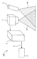
- FIG. 1 It is a perspective view which shows the speed measuring device which concerns on embodiment.
- FIG. 1 is a block diagram which shows the structure of the data processor shown in FIG.
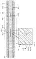
- FIG. 1 is a top view which shows a sleeper and the visual field area
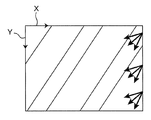
- FIG. It is a top view which shows an example of the image imaged with the line sensor camera shown.
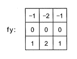
- FIG. shows an example of the SOBEL operator fy used with the differential filter shown in FIG.
- FIG. 1 is a perspective view showing a speed measuring device 100 according to the embodiment.
- FIG. 2 is a block diagram showing the configuration of the data processing device 3 shown in FIG. 3A is a plan view showing a sleeper and a visual field area A1 of the line sensor camera 1 that images the sleeper 22 when the speed measuring device 100 shown in FIG.
- FIG. 3B is a plan view showing an example of an image (second image data described later) captured by the line sensor camera 1 shown in FIG.
- the speed measuring device 100 is installed under the floor of a railway vehicle 200 that moves in a predetermined traveling direction along the rails 21a and 21b. As shown in FIG. 1, the speed measuring device 100 includes a line sensor camera 1 as an “imaging unit”, a laser line projector 2, and a data processing device 3.
- the line sensor camera 1 is a “linear array sensor” in which a plurality of sensor elements are arranged side by side, and an imaging line (field-of-view area A1) in the main scanning direction that is substantially parallel to the traveling direction of the railway vehicle 200.
- the main scanning direction (hereinafter also referred to as “X direction”) refers to a direction in which a plurality of sensor elements of the line sensor camera 1 are arranged.
- the line sensor camera 1 images the sleepers 22 at a constant cycle (predetermined time interval).
- first image data in which data from the sensor elements of the line sensor camera 1 are arranged in the main scanning direction is obtained every time imaging is performed. It is done.
- the line sensor camera 1 outputs the obtained first image data to the data processing device 3 for each cycle.
- the sleepers 22 support a pair of rails 21a and 21b on which the railway vehicle 200 travels in the traveling direction D200, and face the railway vehicle 200 on the ground (ground). Is installed.
- the dotted line 200 indicates the outline of the appearance of the railway vehicle.
- the laser line projector 2 assists the imaging of the line sensor camera 1, and illuminates the sleeper 22 when the surroundings are dark and the line sensor camera 1 cannot clearly image the sleeper 22 that is the imaging target.
- the laser line projector 2 is arranged so that the illumination area A ⁇ b> 2 of the laser beam overlaps the visual field area A ⁇ b> 1 of the line sensor camera 1.
- the laser line projector 2 may not be equipped when the imaging target can be clearly imaged, or the illumination thereof may be turned off.
- what illuminates the sleepers 22 is not limited to the laser line projector 2, and may be, for example, a line projector that does not use laser light.
- the data processing device 3 calculates the speed (speed data 5) of the railway vehicle 200 based on the image data obtained by the imaging of the line sensor camera 1, and outputs the speed data 5 to the speed display 4. It is.
- the data processing device 3 includes an image creation circuit 11, a low-pass filter 12, a differential filter 13, a fringe direction angle calculation circuit 14, and a speed conversion circuit 15. .
- the image creating circuit 11 serves as “image creating means”.
- the low-pass filter 12 serves as “filtering means”.
- the differential filter 13, the fringe direction angle calculation circuit 14, and the speed conversion circuit 15 serve as “speed calculation means”.
- the constituent elements 11 to 15 of the data processing device 3 may be combined into a digital control device such as a digital signal processor.
- the components 11 to 15 do not need to be provided integrally as the data processing device 3.
- the image creation circuit 11 may be separated from the data processing device 3 and provided integrally with the line sensor camera 1. .
- the image creation circuit 11 includes a buffer memory 11m.
- the image creation circuit 11 first stores the first image data input from the line sensor camera 1 in the buffer memory 11m.
- the image creating circuit 11 sequentially refers to the input first image data as an arrangement direction (hereinafter referred to as “Y direction”) substantially perpendicular to the main scanning direction. ) Corresponding to the time direction t)) in the above-mentioned fixed cycle.
- the image creation circuit 11 continues the arrangement of the first image data for a predetermined period to create one frame of two-dimensional image data (hereinafter also referred to as “second image data”).
- the image creation circuit 11 outputs the second image data to the low-pass filter 12.
- the line sensor camera 1 moves relative to the sleepers 22. Therefore, as shown in FIG. 3B, in the second image data created from the first image data obtained by imaging the sleeper 22, the image pattern of the sleeper 22 corresponds to the speed of the railway vehicle 200. It becomes a striped pattern inclined in proportion to the angle. That is, the second image data includes a striped pattern based on the sleepers 22.
- the sleeper 22-1 in FIG. 3A appears in the sleeper image P22-1 in FIG. 3B
- the sleeper 22-2 in FIG. 3A becomes the sleeper image P22- in FIG. 3B. 2
- the sleeper 22-3 in FIG. 3A appears in the sleeper image P22-3 in FIG. 3B.
- the low pass filter 12 performs band limitation on the image data.
- the low-pass filter 12 first receives the input of the second image data from the image creation circuit 11.
- the low-pass filter 12 filters the second image data so as to pass only the frequency components below the cut-off frequency, and performs band limitation on the second image data.
- the high frequency component is cut from the second image data, and the density change in the second image data is smoothed and the aliasing noise included in the second image data is removed.
- the low-pass filter 12 outputs the second image data after band limitation to the differential filter 13.
- the differential filter 13 obtains density gradients in the X direction and the Y direction for each pixel of the second image data.
- the differential filter 13 first receives the input of the second image data after performing the band limitation from the low-pass filter 12.
- the differential filter 13 uses a SOBEL operator fx in the X direction and a SOBEL operator fy in the Y direction for each pixel (and pixels around the target pixel) of the second image data, and will be described later in detail. Perform filtering. Thereby, the density gradient of each pixel is obtained in the X direction and the Y direction.
- the differential filter 13 performs the same processing for each pixel of the second image data, and obtains the density gradients in the X direction and the Y direction for all the pixels of the second image data. Then, the differential filter 13 outputs density gradients in the X direction and Y direction of all the pixels of the second image data to the fringe direction angle calculation circuit 14.
- the fringe direction angle calculation circuit 14 represents a representative value ⁇ of the direction angle of the fringe pattern included in the second image data based on the density gradients of all the pixels constituting the second image data (FIG. 3 ( b) is calculated.
- the fringe direction angle calculation circuit 14 receives, from the differential filter 13, the density gradients in the X direction and Y direction of all the pixels constituting the second image data.
- the fringe direction angle calculation circuit 14 uses the following equation to calculate the direction angle of the density gradient in each pixel (hereinafter also referred to as “density gradient direction angle ⁇ ”) from the density gradient in the X direction and Y direction for each pixel. ).
- the fringe direction angle calculation circuit 14 performs the same calculation for each pixel, and obtains the respective density gradient direction angles ⁇ for all the pixels constituting the second image data. Then, the fringe direction angle calculation circuit 14 calculates an average value of the density gradient direction angles ⁇ for all the pixels (entire second image data) from the density gradient direction angle ⁇ of each pixel, and this density gradient direction angle The average value of ⁇ is output to the speed conversion circuit 15 as a representative value ⁇ of the direction angle of the stripe pattern included in the second image data.
- the representative value ⁇ of the direction angle of the stripe pattern included in the second image data is the average value of the density gradient direction angles ⁇ of all the pixels, but is not limited thereto.
- a histogram of the density gradient direction angles ⁇ of all the pixels may be taken, and the mode value may be used as the representative value ⁇ of the direction angle of the stripe pattern.
- the speed conversion circuit 15 obtains the speed of the railway vehicle 200.
- the speed conversion circuit 15 determines the relationship between the representative value ⁇ of the direction angle of the stripe pattern and the speed of the railway vehicle 200 corresponding to the representative value ⁇ of the direction angle of the stripe pattern (the speed of the railway vehicle 200 is high). If this is the case, a proportional relationship in which the representative value ⁇ of the direction angle of the stripe pattern increases is obtained in advance, and the conversion coefficient (proportional constant) (or a conversion table) may be stored in the internal memory in the speed conversion circuit 15. Storing. First, the speed conversion circuit 15 acquires a representative value ⁇ of the direction angle of the stripe pattern in the entire second image data from the stripe direction angle calculation circuit 14. Next, the speed conversion circuit 15 converts the representative value ⁇ of the direction angle of the stripe pattern into the speed (speed data 5) of the railway vehicle 200 using the conversion coefficient described above. Then, the speed conversion circuit 15 outputs the speed data 5 to the speed indicator 4.
- FIG. 4A is a diagram showing an example of the SOBEL operator fx used in the differential filter 13 shown in FIG. 2
- FIG. 4B is a diagram showing an example of the SOBEL operator fy used in the differential filter 13 shown in FIG.
- the SOBEL operator is an operator for extracting an edge from the pixel of the image data.
- the magnitude of the density gradient and the direction angle of the density gradient can be obtained for each pixel of the image data.
- fx in FIG. 4A and fy in FIG. 4B To calculate the magnitude of the concentration gradient.
- To calculate the direction angle of the concentration gradient. this is utilized.
- the differential filter 13 and the fringe direction angle calculation circuit 14 perform total differential processing (image data after processing by the SOBEL operator fx and after processing by the SOBEL operator fy in the Y direction corresponding to the time direction).
- the image data after addition) is subjected to density projection while changing the representative value ⁇ of the direction angle of the fringe pattern, and the dispersion of the obtained density distribution is evaluated. It can also be converted to speed by selecting the angle at which the variance value is the largest.
- the density gradient is obtained using the SOBEL operators fx and fy, and the direction angle of the stripe pattern is obtained from the density gradient.
- the present invention is not limited to this, and is shown in FIG.
- the direction in which the square integrated value of the differential value of the density on the line in the image data is the largest may be detected as the direction angle of the stripe pattern while changing the starting point and angle on the image. That is, in the image data, the direction in which the density value is the most intense and frequently changes may be used as the representative value of the direction angle of the stripe pattern included in the second image data.
- the processing in the direction may be performed before or after the processing of the SOBEL operators fx and fy, or may be used after processing of only one of the SOBEL operators fx and fy.
- the data processing device 3 does not perform decimation processing during the data processing.
- the present invention is not limited to this, and as shown in FIG. 6, in the data processing device 3, a decimation filter 16 as a “resolution conversion unit” is further provided between the image creation circuit 11 and the low-pass filter 12.
- the decimation process may be performed a plurality of times on the image data.
- the decimation filter 16 performs a decimation process on the image data and converts the resolution of the image data. For example, the decimation filter converts resolution of 1000 (X direction) ⁇ 1000 (Y direction) image data into, for example, 1000 (X direction) ⁇ 250 (Y direction) image data.
- the decimation filter 16 is provided in the data processing device 3, the decimation filter 16 is provided between the image creation circuit 11 and the low-pass filter 12 as shown in FIG. 6.
- the decimation filter 16 receives input of second image data from the image creation circuit 11.
- the decimation filter 16 performs decimation processing on the second image data and converts the resolution of the second image data.
- the second image data whose resolution is converted is output to the low-pass filter 12.
- the low-pass filter 12 reduces the cut-off frequency when performing band limitation in the direction in which the resolution is reduced (thinning is performed). For example, when converting the resolution of 1000 (X direction) ⁇ 1000 (Y direction) image data to 1000 (X direction) ⁇ 250 (Y direction) image data, the low-pass filter 12 Band limiting is performed by setting the cutoff frequency in the Y direction to 1 ⁇ 4 of the cutoff frequency in the X direction. Thereby, it is possible to obtain a high accuracy by expanding the detection range and integrating the results.
- the measurement accuracy of the speed of the moving object can be changed by changing the resolution of the image data.
- the resolution of the image data is set to a predetermined first resolution within a predetermined first speed range, and the resolution of the image data is set to a predetermined second speed range different from the first speed range.
- the decimation process is performed in order to change the resolution.
- the present invention is not limited to this, and the resolution may be changed by changing the sampling speed or by various other methods.
- FIGS. 7A, 7B, 7C, and 7D show images of second image data obtained by changing the resolution in each case where the speed of the railway vehicle 200 is different from each other.
- FIG. 5 is a diagram illustrating a high-speed resolution image, a medium-speed resolution image, and a low-speed resolution image.
- FIG. 7A shows the images V11 to V13 of Case 1 at the lowest speed. At the lowest speed, a predetermined measurement accuracy can be obtained by performing speed measurement using the images V12 and V13.
- FIG. 7B shows the images V21 to V23 of the case 2 at a medium speed faster than that in FIG. 7A. Even if the images approach the medium speed, the images V22 and V23 can be selected to measure the speed.
- FIG. 7C shows the images V31 to V33 of the case 3 at high speed, which is faster than that of FIG. 7B. If the inclination of the striped pattern exceeds a predetermined threshold, for example, the images V31, V31, A predetermined measurement accuracy can be obtained by selecting V32 and measuring the speed. Furthermore, FIG. 7 (d) shows the images V41 to V43 of the case 4 at the highest speed that is faster than that of FIG. 7 (c). If the images V41 and V42 are selected, the angle is always greater than or equal to a predetermined threshold value. A predetermined measurement accuracy can be obtained by using.
- the decimation filter 16 is configured to generate a plurality of image data having different resolutions, and the differential filter 13, the fringe direction angle calculation circuit 14, and the speed conversion circuit 15 are included in the plurality of image data.
- the direction angle of the stripe pattern is calculated from the image data that can obtain the accuracy of the predetermined speed measurement (or the accuracy of the speed measurement equal to or higher than the predetermined threshold), and is converted into the speed of the railway vehicle 200. You may comprise as follows.
- the speed of the railway vehicle is calculated based on image data obtained by imaging a sleeper.
- the imaging target is not limited to this, and the speed of the moving body may be calculated based on an image of an object provided facing the moving body, such as a flipping machine, regardless of sleepers.
- the moving body is not limited to a railway vehicle, and may be a moving body such as an automobile, and a striped pattern can be obtained based on an object provided facing the floor or the side of the moving body, for example. The speed can be obtained based on the representative value of the direction angle of the stripe pattern.
- the illuminated image is captured by the line sensor camera.
- the present invention is not limited to this, and the image captured by the line sensor camera is illuminated with light having a predetermined wavelength.
- Image processing may be performed by filtering data using a band-pass filter that passes only the wavelength. Thereby, noise due to other light wavelengths can be removed, and an accurate speed can be calculated.
- the low-pass filter is used.
- the noise component included in the image digital data from the image creating circuit is relatively small, the low-pass filter may not be provided.
- a line sensor camera is used.
- the imaging means is not limited to this, and may be a so-called linear array sensor configured by arranging a plurality of detection elements in a line.
- the first image data may be obtained at a low cost by partially capturing (partial scan) a part (one line to several lines) of the central scanning line of an inexpensive area sensor.
- the speed of the moving body can be measured with a simple configuration using the imaging means.
- the imaging means captures an object placed on the ground side and measures the speed of the moving object based on the image data obtained by the imaging, the distance between the moving object and the imaging target varies.
- the object for irradiating the laser light or microwave may be a sleeper near the railway vehicle, In some cases, the distance may be a distant ground or water surface, and the distance between the railway vehicle and the object to be irradiated with laser light or microwaves will vary greatly. Therefore, the conventional speed measurement device using laser light or microwave may not be able to measure the accurate speed of the railway vehicle moving on the bridge.
- the velocity measuring device according to the present embodiment solves this problem by taking a wide field of view with a configuration using a line sensor camera.
- the speed measuring device of the present invention it is possible to provide a speed measuring device that can measure the speed more accurately than the prior art and has a simple configuration. it can. For example, by measuring the speed of the vehicle, the position of the vehicle can be measured more accurately in the vehicle inspection system, and the inspection accuracy is greatly improved. Further, in the running state of the vehicle, it is possible to accurately detect and measure the idling / sliding state together with the conventional speedometer.
Landscapes
- Engineering & Computer Science (AREA)
- Physics & Mathematics (AREA)
- Mechanical Engineering (AREA)
- Electromagnetism (AREA)
- Power Engineering (AREA)
- General Physics & Mathematics (AREA)
- Length Measuring Devices By Optical Means (AREA)
Abstract
速度計測装置(100)は、所定の進行方向に移動する移動体(200)に適用可能であり、移動体(200)の進行方向と略平行な主走査方向の撮像ライン(A1)を有し、移動体(200)に対向し地上に設置された枕木(22)を撮像し、撮像により得られた第一の画像データを出力する撮像手段(1)と、第一の画像データを、主走査方向とは平行でない配列方向へ、所定の時間ごとに配列して、物体(22)に基づく縞模様を含む二次元の第二の画像データを作成し、第二の画像データを出力する画像作成手段(11)と、第二の画像データの縞模様の縞の方向角度を計算し、縞模様の縞の方向角度が移動体(200)の速度に比例する関係を用いて、縞模様の縞の方向角度から移動体(200)の速度を算出して、速度データとして出力する速度算出手段(13~15)と、を備えている。
Description
本発明は、例えば車両などの移動体の速度を計測する速度計測装置に関する。
一般的に車両などの移動体から速度を正確に得ることは難しく、多くは車輪の回転パルスを積算して、積算されたパルスを速度に換算して、速度を計測している(例えば、特許文献1参照。)。例えば、特許文献1において開示された速度算出方法では、正確な速度を算出するために、車輪を回転させる車軸の回転によって生じる速度パルスから車両1の速度Vnを算出することを特徴としている。具体的には、パルスカウント時間間隔TZを等分した複数の速度演算時間間隔TSの少なくとも1つにおいて速度パルスが発生しない場合に、速度パルスが発生しない速度演算時間間隔TSの個数及び配列と、速度パルスが発生した速度演算時間間隔TSにおける速度パルス数とに基づいて、所定の速度と、前回算出した速度Vn-1と、速度演算値V’nとのいずれか1つを速度Vnとし、速度演算値V’nは、パルスカウント時間間隔TZ内に発生する速度パルス数P及びパルスカウント時間間隔TZ内の最初の速度パルスから最後の速度パルスまでの時間間隔Tに基づいて算出する。
しかし、車輪や車軸から速度を計測する場合、空転・滑走などの現象が頻発し、正確な車両速度が得られない問題があった。これに対し、複数の車軸からのパルスを利用して空転を補おうとする技術や、速度測定のためだけの自由車輪を利用するなどの方法も提案されているが、構造が複雑となり、コストが多大になるという問題があった。
これに対し、速度を非接触に測定する既存の技術として、レーザ光又はマイクロ波を用いたドップラー速度計、空間フィルタ式速度計が知られている。これらのドップラー速度計や空間フィルタ式速度計は、レーザ光又はマイクロ波の照射のタイミングによって、移動体とレーザ光を照射する対象との距離が変動する場合には、その距離の変動幅によっては正確な速度が算出できないという問題があった。
そこで本発明は、正確に速度を計測することができ、しかも構成が簡単である速度計測装置を提供することを目的とする。
本発明の速度計測装置は、所定の進行方向に移動する移動体に適用可能な速度計測装置であって、前記移動体の前記進行方向と略平行な主走査方向の撮像ラインを有し、前記移動体に対向し地上に設置された物体を撮像し、撮像により得られた第一の画像データを出力する撮像手段と、前記第一の画像データを、前記主走査方向とは平行でない配列方向へ、所定の時間ごとに配列して、前記物体に基づく縞模様を含む二次元の第二の画像データを作成し、該第二の画像データを出力する画像作成手段と、前記第二の画像データの縞模様の縞の方向角度を計算し、前記縞模様の縞の方向角度が前記移動体の速度に比例する関係を用いて、前記縞模様の縞の方向角度から前記移動体の速度を算出して、速度データとして出力する速度算出手段と、を備えている。
前記構成によれば、撮像手段を用いた簡単な構成により、移動体の速度を計測することができる。撮像手段により、地上側に設置された物体を撮像し、撮像により得られた画像データに基づき、移動体の速度を計測するため、移動体と撮像対象との距離が変動する場合であっても、移動体の正確な速度を計測することができる。
以上の説明から明らかなように、本発明によれば、正確に移動体の速度を計測することができ、しかも構成が簡単である速度計測装置を提供することができる。
以下、本発明に係る実施形態について図面を参照して説明する。なお、以下の各実施形態において、同様の構成要素については同一の符号を付している。
図1は実施形態に係る速度計測装置100を示す斜視図である。図2は、図1に示すデータ処理装置3の構成を示すブロック図である。また、図3(a)は、枕木と、図1に示す速度計測装置100を鉄道車両200の床下に装備したときに枕木22を撮像するラインセンサカメラ1の視野領域A1とを示す平面図であり、図3(b)は、図1に示すラインセンサカメラ1により撮像された画像(後述する第二の画像データ)の一例を示す平面図である。
本実施形態に係る速度計測装置100は、レール21a,21bに沿って所定の進行方向に移動する鉄道車両200の床下等に装備されている。そして、速度計測装置100は、図1に示すように、「撮像手段」としてのラインセンサカメラ1と、レーザラインプロジェクタ2と、データ処理装置3とを備えている。
ラインセンサカメラ1は、複数のセンサ素子が、並んで配置されている「リニアアレイセンサ」であり、鉄道車両200の進行方向に対して略平行な主走査方向の撮像ライン(視野領域A1)を有している。なお、ここでは、主走査方向(以降、「X方向」ともいう)とは、ラインセンサカメラ1の複数のセンサ素子が並べられている方向を指すものとする。ラインセンサカメラ1は、一定のサイクル(所定の時間間隔)で、枕木22を撮像する。ここでは、1回の撮像を行う度に、ラインセンサカメラ1の各センサ素子からのデータが主走査方向に並んだ一次元の画像データ(以降、「第一の画像データ」ともいう)が得られる。そして、ラインセンサカメラ1は、各サイクルごとに、得られた第一の画像データをデータ処理装置3へ出力する。なお、図3(a)に示すように、枕木22は鉄道車両200が進行方向D200で走行する1対のレール21a,21bを支持するものであり、鉄道車両200に対向して地上(地面)に設置されている。なお、図3(a)において、符号200の点線は鉄道車両の外観の輪郭を示す。
レーザラインプロジェクタ2は、ラインセンサカメラ1の撮像を補助するものであり、周囲が暗く、ラインセンサカメラ1が撮像対象である枕木22を明確に撮像できないときに、枕木22を照明する。図1に示すように、レーザラインプロジェクタ2は、そのレーザ光の照明領域A2が、ラインセンサカメラ1の視野領域A1と重なるように配置されている。なお、レーザラインプロジェクタ2については、撮像対象を明確に撮像できるときは、装備しなくてもよいし、もしくはその照明をオフとしてもよい。また、枕木22を照明するものとしては、レーザラインプロジェクタ2に限定されず、例えば、レーザ光を用いないラインプロジェクタ等であってもよい。
データ処理装置3は、ラインセンサカメラ1の撮像により得られた画像データに基づいて、鉄道車両200の速度(速度データ5)を計算して、その速度データ5を速度表示器4に出力するものである。図2に示すように、データ処理装置3は、画像作成回路11と、低域通過フィルタ12と、微分フィルタ13と、縞方向角度計算回路14と、速度変換回路15と、を有している。ここでは、画像作成回路11が「画像作成手段」としての役割を果たす。また、低域通過フィルタ12が「フィルタ手段」としての役割を果たす。また、微分フィルタ13、縞方向角度計算回路14、及び、速度変換回路15が「速度算出手段」としての役割を果たす。なお、データ処理装置3の各構成要素11~15をまとめてデジタル・シグナル・プロセッサなどのデジタル制御装置などで構成してもよい。他方で、各構成要素11~15は、データ処理装置3として一体的に設ける必要もなく、例えば画像作成回路11をデータ処理装置3とは分離させ、ラインセンサカメラ1と一体に設けてもよい。
画像作成回路11は、バッファメモリ11mを含んだ構成となっている。画像作成回路11は、まず、ラインセンサカメラ1から入力された第一の画像データを、バッファメモリ11mに格納する。つぎに、画像作成回路11は、バッファメモリ11mにおいて、この入力された第一の画像データを、順次、主走査方向と略垂直な配列方向(以降、「Y方向」ともいい、図3(b)の時間方向tに対応する)へ、上述の一定のサイクルごとに配列していく。それから、画像作成回路11は、所定の期間、第一の画像データの配列を続けて、一フレームの二次元の画像データ(以降、「第二の画像データ」ともいう)を作成する。そして、画像作成回路11は、第二の画像データを低域通過フィルタ12へ出力する。鉄道車両200がレール21a,21bに沿って移動するとき、ラインセンサカメラ1は、枕木22に対して相対移動することとなる。そのため、図3(b)に示すように、枕木22を撮像して得られた第一の画像データから作成された第二の画像データにおいて、枕木22の画像パターンは、鉄道車両200の速度に比例して斜めに傾いた縞模様となる。つまり、第二の画像データは、枕木22に基づく縞模様を含むものとなる。ここで、例えば図3(a)の枕木22-1が図3(b)の枕木画像P22-1に表れ、図3(a)の枕木22-2が図3(b)の枕木画像P22-2に表れ、図3(a)の枕木22-3が図3(b)の枕木画像P22-3に表れている。
低域通過フィルタ12は、画像データに対して、帯域制限を行うものである。低域通過フィルタ12は、まず、画像作成回路11から、第二の画像データの入力を受ける。つぎに、低域通過フィルタ12は、第二の画像データから、遮断周波数の以下の周波数成分のみを通過させるようにろ波し、第二の画像データに対して、帯域制限を行う。これにより、第二の画像データから高周波成分がカットされて、第二の画像データにおける濃度変化の平滑化と、第二の画像データに含まれるエイリアシングノイズの除去とが行われることとなる。そして、低域通過フィルタ12は、帯域制限を行った後の第二の画像データを、微分フィルタ13へ出力する。
微分フィルタ13は、第二の画像データの各画素ごとに、X方向とY方向の濃度勾配を求めるものである。微分フィルタ13は、まず、低域通過フィルタ12から、帯域制限を行った後の第二の画像データの入力を受ける。つぎに、微分フィルタ13は、第二の画像データの各画素(及び注目画素周辺の画素)に対し、X方向のSOBELオペレータfxと、Y方向のSOBELオペレータfyとを用いて、詳細後述する微分フィルタ処理を実行する。これにより、各画素の濃度勾配が、X方向とY方向に対して、求まることとなる。それから、微分フィルタ13は、第二の画像データの各画素それぞれに同様の処理を実行し、第二の画像データの全ての画素に対して、それぞれのX方向とY方向の濃度勾配を求める。そして、微分フィルタ13は、第二の画像データの全ての画素それぞれのX方向とY方向の濃度勾配を、縞方向角度計算回路14へ出力する。
縞方向角度計算回路14は、第二の画像データを構成する全ての画素それぞれの濃度勾配に基づいて、第二の画像データに含まれる縞模様の縞の方向角度の代表値θ(図3(b)参照)を計算するものである。縞方向角度計算回路14は、まず、微分フィルタ13から、第二の画像データを構成する全ての画素それぞれのX方向とY方向の濃度勾配の入力を受ける。つぎに、縞方向角度計算回路14は、各画素ごとのX方向及びY方向の濃度勾配から、次式を用いて、各画素における濃度勾配の方向角度(以降「濃度勾配方向角度α」ともいう)を計算する。それから、縞方向角度計算回路14は、各画素ごとに同様の計算を実行し、第二の画像データを構成する全ての画素に対して、それぞれの濃度勾配方向角度αを求める。そして、縞方向角度計算回路14は、各画素それぞれの濃度勾配方向角度αから、全ての画素(第二の画像データ全体)に対する濃度勾配方向角度αの平均値を計算し、この濃度勾配方向角度αの平均値を、第二の画像データに含まれる縞模様の縞の方向角度の代表値θとして、速度変換回路15へ出力する。なお、ここでは、第二の画像データに含まれる縞模様の縞の方向角度の代表値θを、全ての画素の濃度勾配方向角度αの平均値としているが、これに限定されず、例えば、全ての画素の濃度勾配方向角度αのヒストグラムをとって、その最頻値を、縞模様の縞の方向角度の代表値θとしてもよい。

速度変換回路15は、鉄道車両200の速度を求めるものである。速度変換回路15は、縞模様の縞の方向角度の代表値θと、縞模様の縞の方向角度の代表値θに対応する鉄道車両200の速度との関係を(鉄道車両200の速度が速くなれば、縞模様の縞の方向角度の代表値θが大きくなる比例関係)を予め求めておき、その変換係数(比例定数)(又は変換テーブルでもよい)を速度変換回路15内の内部メモリに格納している。速度変換回路15は、まず、縞方向角度計算回路14から第二の画像データ全体における縞模様の縞の方向角度の代表値θを取得する。つぎに、速度変換回路15は、上述の変換係数を用いて、縞模様の縞の方向角度の代表値θを、鉄道車両200の速度(速度データ5)に変換する。そして、速度変換回路15は、当該速度データ5を、速度表示器4へ出力する。
図4Aは図2に示す微分フィルタ13で用いるSOBELオペレータfxの一例を示す図であり、図4Bは図2に示す微分フィルタ13で用いるSOBELオペレータfyの一例を示す図である。ここで、SOBELオペレータは画像データの画素からエッジ抽出のための演算子であり、これを用いることで、画像データの各画素において、濃度勾配の大きさと、濃度勾配の方向角度を求めることができる。例えば、図4Aのfxと図4Bのfyに対して、
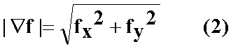
で濃度勾配の大きさを計算することができる。また、
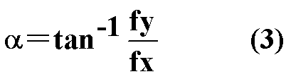
で濃度勾配の方向角度を計算することができる。そして、本実施形態ではこれを利用している。
なお、以上の実施形態においては、微分フィルタ13及び縞方向角度計算回路14において、全微分処理(SOBELオペレータfxの処理後の画像データと、時間方向に対応するY方向のSOBELオペレータfyの処理後の画像データとを加算して合成する処理)後の画像データについて、縞模様の縞の方向角度の代表値θを変化させながら濃度投影し、得られた濃度分布の分散を評価することで、分散値が最も大きくなる角度を選ぶことでも速度に変換できる。
なお、以上の実施形態においては、SOBELオペレータfx,fyを用いて濃度勾配を求めて、この濃度勾配から縞模様の縞の方向角度を求めているが、これに限定されず、図5に示すように、画像上の出発点及び角度を変えつつ、画像データにおけるライン上の濃度の微分値の二乗積算値が一番大きい方向を縞模様の縞の方向角度として検出してもよい。つまり、画像データにおいて、濃度値が最も激しく、高頻度に変化する方向を、第二の画像データに含まれる縞模様の縞の方向角度の代表値としてもよい。当該方向の処理は、SOBELオペレータfx,fyの処理前もしくは処理後に行ってもよいし、各SOBELオペレータfx,fyの片方のみの処理後に使用してもよい。
図2に示すように、以上の実施形態においては、データ処理装置3は、そのデータ処理の過程において、デシメーション処理は行っていない。しかし、これに限定されず、図6に示すように、データ処理装置3において、画像作成回路11と低域通過フィルタ12との間に、「解像度変換手段」としてのデシメーションフィルタ16をさらに設けて、画像データに対して複数回デシメーション処理を行ってもよい。
デシメーションフィルタ16は、画像データに対してデシメーション処理を行い、画像データの解像度を変換するものである。例えば、デシメーションフィルタは、1000(X方向)×1000(Y方向)の画像データを、例えば1000(X方向)×250(Y方向)の画像データに解像度変換する。データ処理装置3にデシメーションフィルタ16を設けた場合、図6に示すように、デシメーションフィルタ16は、画像作成回路11と、低域通過フィルタ12との間に設けられる。デシメーションフィルタ16は、まず、画像作成回路11から、第二の画像データの入力を受ける。つぎに、デシメーションフィルタ16は、第二の画像データに対してデシメーション処理を行い、第二の画像データの解像度を変換する。そして、解像度を変換した第二の画像データを、低域通過フィルタ12へ出力する。
なお、画像データに対してデシメーション処理を行う場合、エイリアシングを避けるため、低域通過フィルタ12を作用させた後に、再サンプリング(間引き)が行われる。ここで、低域通過フィルタ12は、解像度を落とす(間引きを行う)方向に対して、帯域制限を行う際の遮断周波数を小さくする。例えば、1000(X方向)×1000(Y方向)の画像データを、1000(X方向)×250(Y方向)の画像データに解像度変換する場合、低域通過フィルタ12は画像データに対して、Y方向の遮断周波数を、X方向の遮断周波数の1/4として、帯域制限を行う。これにより、検出レンジを広げ、結果を統合することで高い精度を得ることが可能である。すなわち、鉄道車両200の速度は縞模様の縞の方向角度の代表値θに比例するので、画像データの解像度を変更することで、移動体の速度の計測精度を変更することができる。具体的には、所定の第1の速度範囲で画像データの解像度を所定の第1の解像度とし、上記第1の速度範囲とは異なる所定の第2の速度範囲で画像データの解像度を上記第1の解像度よりも高くすることで、上記第2の速度範囲での速度計測の精度を、上記第1の速度範囲での速度計測の精度よりも高くすることができる。
また、上記の方法では、解像度を変えるためにデシメーション処理を行っているが、これに限定されず、サンプリング速度を変えて、もしくは他の種々の方法で解像度を変化してもよい。
図7(a)、(b)、(c)及び(d)は、鉄道車両200の速度がそれぞれ互いに異なる各事例において、解像度を変化して得られた第二の画像データの画像を示したものである。また、高速用解像度の画像、中速用解像度の画像及び低速用解像度の画像を示す図である。図7(a)は最低速時の事例1の各画像V11~V13を示し、最低速時には、画像V12及びV13を用いて速度計測を行うことで所定の計測精度を得ることができる。また、図7(b)は図7(a)よりも速い中速時の事例2の各画像V21~V23を示し、中速に近づいても画像V22,V23を選択して速度計測しても「傾斜が急すぎる」という問題は起こらず、計測するうえで都合がよいいずれか画像V22,V23を選択して速度計測を行うことができる。さらに、図7(c)は図7(b)よりも速い高速時の事例3の各画像V31~V33を示し、縞状のパターンの傾斜が所定のしきい値を越えれば、例えば画像V31,V32を選択して速度計測することで所定の計測精度を得ることができる。またさらに、図7(d)は図7(c)よりも速い最高速時の事例4の各画像V41~V43を示し、画像V41,V42を選択すれば、常に所定のしきい値以上の角度を使用することで所定の計測精度を得ることができる。従って、デシメーションフィルタ16は、互いに異なる解像度を有する複数の画像データを生成するように構成し、微分フィルタ13、縞方向角度計算回路14、及び、速度変換回路15は、当該複数の画像データのうち、所定の速度計測の精度(もしくは、所定のしきい値以上の速度計測の精度)を得られる画像データから、縞模様の縞の方向角度を計算して、上記鉄道車両200の速度に変換するように構成してもよい。
なお、以上の実施形態においては、図3(a)及び(b)に示すように、枕木を撮像して得られた画像データに基づいて鉄道車両の速度を計算している。枕木が例えば60cm間隔で配置されているときは、好ましくは、少なくとも2本程度の枕木が撮像可能なようにラインセンサカメラの撮像ライン長を選択することが好ましい。ここで、撮像対象はこれに限らず、枕木に関わらず、転てつ機など、移動体に対向して設けられた物体の画像に基づいて移動体の速度を計算してもよい。また、移動体は鉄道車両に限定されず、自動車などの移動体であってもよく、移動体の例えば床下又は側面などに対向して設けられた物体に基づいて縞模様を得ることができ、その縞模様の縞の方向角度の代表値に基づいて速度を得ることができる。
なお、以上の実施形態においては、照明された画像をラインセンサカメラにより取り込んでいるが、これに限定されず、所定の波長を有する光を用いて照明して、ラインセンサカメラにより撮像された画像データを当該波長のみを通過させる帯域通過フィルタを用いてろ波してその画像処理を行ってもよい。これにより、他の光波長によるノイズを除去でき、正確な速度を計算できる。
なお、以上の実施形態において、低域通過フィルタを用いているが、画像作成回路からの画像デジタルデータに含まれるノイズ成分が比較的小さいときは、低域通過フィルタを設けなくてもよい。
なお、以上の実施形態においては、ラインセンサカメラを用いているが、撮像手段はこれに限定されず、複数の検出素子が一列に並置されて構成されたいわゆるリニアアレイセンサであればよく、例えば、安価なエリアセンサの中央部走査線の一部(1ライン~数ライン)を部分取り込み(パーシャルスキャン)することにより第一の画像データを得て、低コストに実現してもよい。
以上説明したように、本実施形態に係る速度計測装置によれば、撮像手段を用いた簡単な構成により、移動体の速度を計測することができる。また、撮像手段により、地上側に設置された物体を撮像し、撮像により得られた画像データに基づき、移動体の速度を計測するため、移動体と撮像対象との距離が変動する場合であっても、移動体の正確な速度を計測することができる。例えば、鉄道車両の橋梁においては、隣り合う枕木の間はいずれも設けられておらず、鉄道車両と、レーザ光又はマイクロ波を照射するための対象(例えば、地面や水面)との距離が遠い場合が多い。そのため、従来のレーザ光又はマイクロ波を用いた速度計測装置では、レーザ光又はマイクロ波を照射するための対象が、照射のタイミングによっては、鉄道車両の近くの枕木となる場合と、鉄道車両から遠くの地面や水面となる場合とがあり、鉄道車両とレーザ光又はマイクロ波を照射する対象との距離が大きく変動することとなる。よって、従来のレーザ光又はマイクロ波を用いた速度計測装置では、橋梁上を移動する鉄道車両の正確な速度を計測することができない場合があった。一方、本実施形態に係る速度計測装置では、ラインセンサカメラを用いた構成により、視野を広く取り、この問題を解決している。また、従来のマイクロ波を用いた速度計測装置では、法規制により、マイクロ波の使用が制限されることがあり、速度計測装置自体の使用が制限されるという問題があったが、本実施形態に係る速度計測装置では、ラインセンサカメラを用いることで、この問題を解決している。
以上詳述したように、従って、本発明に係る速度計測装置によれば、従来技術に比較して正確に速度を計測することができ、しかも構成が簡単である速度計測装置を提供することができる。例えば車両の速度を測定することで、車両検査システムにおいて自己の位置をより正確に測定することができ、検査確度が大幅に向上する。また、車両の走行状態において、従来の速度計と合わせて、空転・滑走状態を正確に検知して測定できる。
1…ラインセンサカメラ
2…レーザラインプロジェクタ
3…データ処理装置
4…速度表示器
5…速度データ
11…画像作成回路
12…低域通過フィルタ(LPF)
13…微分フィルタ
14…縞方向角度計算回路
15…速度変換回路
16…デシメーションフィルタ
21a,21b…レール
22…枕木
200…鉄道車両
D200…進行方向
2…レーザラインプロジェクタ
3…データ処理装置
4…速度表示器
5…速度データ
11…画像作成回路
12…低域通過フィルタ(LPF)
13…微分フィルタ
14…縞方向角度計算回路
15…速度変換回路
16…デシメーションフィルタ
21a,21b…レール
22…枕木
200…鉄道車両
D200…進行方向
Claims (6)
- 所定の進行方向に移動する移動体に適用可能な速度計測装置であって、
前記移動体の前記進行方向と略平行な主走査方向の撮像ラインを有し、前記移動体に対向し地上に設置された物体を撮像し、撮像により得られた第一の画像データを出力する撮像手段と、
前記第一の画像データを、前記主走査方向とは平行でない配列方向へ、所定の時間ごとに配列して、前記物体に基づく縞模様を含む二次元の第二の画像データを作成し、該第二の画像データを出力する画像作成手段と、
前記第二の画像データの縞模様の縞の方向角度を求め、前記縞模様の縞の方向角度が前記移動体の速度に比例する関係を用いて、前記縞模様の縞の方向角度から前記移動体の速度を算出して、速度データとして出力する速度算出手段と、
を備えた速度計測装置。 - 前記配列方向は前記主走査方向と略垂直となるように設定され、
前記速度算出手段は前記主走査方向の濃度勾配と、前記配列方向の濃度勾配と、に基づいて前記縞模様の縞の方向角度を計算する、請求項1に記載の速度計測装置。 - 前記第二の画像データに対して、帯域制限を行った後、前記速度算出手段へ出力するフィルタ手段をさらに備える、請求項1又は2に記載の速度計測装置。
- 前記速度算出手段は、前記第二の画像データを構成する各画素ごとに濃度勾配の方向角度を計算し、計算した各画素ごとの前記濃度勾配の方向角度から、前記第二の画像データの全画素に対する平均値を計算し、該平均値を前記縞模様の縞の方向角度とする、請求項1~3のいずれかに記載の速度計測装置。
- 前記第二の画像データの解像度を変更することにより、前記移動体の速度の計測精度を変更する解像度変換手段をさらに備える、請求項1~4のいずれかに記載の速度計測装置。
- 前記解像度変換手段は、前記第二の画像データを元に互いに異なる解像度の複数の画像データを生成し、前記速度算出手段は該複数の画像データのうち、所望の前記移動体の速度の計測精度を得られる画像データから、前記縞模様の縞の方向角度を計算する、請求項5に記載の速度計測装置。
Applications Claiming Priority (2)
| Application Number | Priority Date | Filing Date | Title |
|---|---|---|---|
| JP2011223180A JP2015025657A (ja) | 2011-10-07 | 2011-10-07 | 速度計測装置及び方法 |
| JP2011-223180 | 2011-10-07 |
Publications (1)
| Publication Number | Publication Date |
|---|---|
| WO2013051624A1 true WO2013051624A1 (ja) | 2013-04-11 |
Family
ID=48043778
Family Applications (1)
| Application Number | Title | Priority Date | Filing Date |
|---|---|---|---|
| PCT/JP2012/075703 Ceased WO2013051624A1 (ja) | 2011-10-07 | 2012-10-03 | 速度計測装置 |
Country Status (2)
| Country | Link |
|---|---|
| JP (1) | JP2015025657A (ja) |
| WO (1) | WO2013051624A1 (ja) |
Cited By (1)
| Publication number | Priority date | Publication date | Assignee | Title |
|---|---|---|---|---|
| CN109085377A (zh) * | 2018-08-02 | 2018-12-25 | 北京世纪东方通讯设备有限公司 | 一种轨检车的车速检测方法及装置 |
Families Citing this family (2)
| Publication number | Priority date | Publication date | Assignee | Title |
|---|---|---|---|---|
| CN111739098B (zh) * | 2020-06-30 | 2024-05-24 | 上海商汤智能科技有限公司 | 测速方法及装置、电子设备及存储介质 |
| JP7887858B2 (ja) * | 2023-03-31 | 2026-07-10 | 株式会社東芝 | 画像生成装置、および、画像生成方法 |
Citations (5)
| Publication number | Priority date | Publication date | Assignee | Title |
|---|---|---|---|---|
| JPS58205876A (ja) * | 1982-05-26 | 1983-11-30 | Mitsubishi Electric Corp | 車輌用対地速度検出装置 |
| JPS61138167A (ja) * | 1984-12-11 | 1986-06-25 | Nippon Soken Inc | 車両用速度計 |
| JPS6294862A (ja) * | 1985-10-21 | 1987-05-01 | Fuji Xerox Co Ltd | 画像形成装置のトナ−濃度検出装置 |
| JPH0236359A (ja) * | 1988-07-27 | 1990-02-06 | Nissan Motor Co Ltd | 車速計測装置 |
| JPH05164766A (ja) * | 1991-05-31 | 1993-06-29 | Lucas Ind Plc | 速度測定装置 |
-
2011
- 2011-10-07 JP JP2011223180A patent/JP2015025657A/ja active Pending
-
2012
- 2012-10-03 WO PCT/JP2012/075703 patent/WO2013051624A1/ja not_active Ceased
Patent Citations (5)
| Publication number | Priority date | Publication date | Assignee | Title |
|---|---|---|---|---|
| JPS58205876A (ja) * | 1982-05-26 | 1983-11-30 | Mitsubishi Electric Corp | 車輌用対地速度検出装置 |
| JPS61138167A (ja) * | 1984-12-11 | 1986-06-25 | Nippon Soken Inc | 車両用速度計 |
| JPS6294862A (ja) * | 1985-10-21 | 1987-05-01 | Fuji Xerox Co Ltd | 画像形成装置のトナ−濃度検出装置 |
| JPH0236359A (ja) * | 1988-07-27 | 1990-02-06 | Nissan Motor Co Ltd | 車速計測装置 |
| JPH05164766A (ja) * | 1991-05-31 | 1993-06-29 | Lucas Ind Plc | 速度測定装置 |
Cited By (1)
| Publication number | Priority date | Publication date | Assignee | Title |
|---|---|---|---|---|
| CN109085377A (zh) * | 2018-08-02 | 2018-12-25 | 北京世纪东方通讯设备有限公司 | 一种轨检车的车速检测方法及装置 |
Also Published As
| Publication number | Publication date |
|---|---|
| JP2015025657A (ja) | 2015-02-05 |
Similar Documents
| Publication | Publication Date | Title |
|---|---|---|
| CN105393080B (zh) | 架空线测定装置及架空线测定方法 | |
| US8964031B2 (en) | Method and system for measuring the speed of a vehicle | |
| Wang et al. | Development of three-dimensional pavement texture measurement technique using surface structured light projection | |
| EP2861802B1 (en) | Rolling wheel deflectometer | |
| CN105839505B (zh) | 一种三维可视化的路面破损信息的检测方法及检测装置 | |
| WO2018072669A1 (zh) | 辐射检查系统和方法 | |
| JP2019518209A (ja) | トレッド深さ測定 | |
| JP2010091514A (ja) | 表面欠陥検査システム、方法及びプログラム | |
| JP3629532B2 (ja) | 連続移動物体のリアルタイム形状計測方法及びシステム | |
| WO2020080091A1 (ja) | 車両点検装置および方法 | |
| JPH0850182A (ja) | 光学式積雪深計測装置 | |
| JP5631642B2 (ja) | 車両寸法測定方法及び装置 | |
| JP2015025657A (ja) | 速度計測装置及び方法 | |
| JP2009014645A (ja) | 車両用距離測定装置 | |
| KR102211483B1 (ko) | 레이저 어레이 패턴 분석 기반 물체 정보 추정 장치 및 방법 | |
| JP6207435B2 (ja) | 移動体搭載撮影システム | |
| JP2008241609A (ja) | 距離計測システム及び距離計測方法 | |
| JP2681745B2 (ja) | レーザ光を利用したスペックルパターンによる被計測物の上下および横移動量の測定方法。 | |
| JP5228731B2 (ja) | 画像処理による車両のホイル位置計測装置 | |
| JP5375239B2 (ja) | 画像処理装置、長尺物用検査装置及びコンピュータプログラム | |
| JP5634229B2 (ja) | 車両検知システム | |
| JPH11218417A (ja) | 路面凹凸の測定方法および装置 | |
| JP5605491B2 (ja) | シャシーダイナモメータ | |
| JP2008051759A (ja) | 距離計測装置及び距離計測方法 | |
| JP2012098207A (ja) | 位置計測装置、位置計測方法及びマーカー |
Legal Events
| Date | Code | Title | Description |
|---|---|---|---|
| 121 | Ep: the epo has been informed by wipo that ep was designated in this application |
Ref document number: 12838670 Country of ref document: EP Kind code of ref document: A1 |
|
| NENP | Non-entry into the national phase |
Ref country code: DE |
|
| 122 | Ep: pct application non-entry in european phase |
Ref document number: 12838670 Country of ref document: EP Kind code of ref document: A1 |
|
| NENP | Non-entry into the national phase |
Ref country code: JP |