WO2013046741A1 - ダンプボディの振れ止め構造 - Google Patents
ダンプボディの振れ止め構造 Download PDFInfo
- Publication number
- WO2013046741A1 WO2013046741A1 PCT/JP2012/053501 JP2012053501W WO2013046741A1 WO 2013046741 A1 WO2013046741 A1 WO 2013046741A1 JP 2012053501 W JP2012053501 W JP 2012053501W WO 2013046741 A1 WO2013046741 A1 WO 2013046741A1
- Authority
- WO
- WIPO (PCT)
- Prior art keywords
- mounting seat
- steadying
- bracket
- plate
- steady
- Prior art date
- Legal status (The legal status is an assumption and is not a legal conclusion. Google has not performed a legal analysis and makes no representation as to the accuracy of the status listed.)
- Ceased
Links
Images


Classifications
-
- B—PERFORMING OPERATIONS; TRANSPORTING
- B60—VEHICLES IN GENERAL
- B60P—VEHICLES ADAPTED FOR LOAD TRANSPORTATION OR TO TRANSPORT, TO CARRY, OR TO COMPRISE SPECIAL LOADS OR OBJECTS
- B60P1/00—Vehicles predominantly for transporting loads and modified to facilitate loading, consolidating the load, or unloading
- B60P1/04—Vehicles predominantly for transporting loads and modified to facilitate loading, consolidating the load, or unloading with a tipping movement of load-transporting element
- B60P1/28—Tipping body constructions
- B60P1/283—Elements of tipping devices
Definitions
- the present invention relates to a dump body steadying structure, and more particularly to a body steadying structure used in a large dump truck.
- each bracket is disposed so as to sandwich the left and right side members of the vehicle body frame, and the vertical portion of each bracket comes close to and faces the abutting plate provided on the side member. In addition, the vertical portion of the bracket abuts against the contact plate, thereby suppressing the shake of the body.
- the bracket Since the bracket needs to be close to the vertical part and the backing plate with a clearance of about 0 to several millimeters secured, the body is assembled on the frame and then assembled on the site. Welded to the bottom surface. By welding after assembling, a predetermined gap dimension can be ensured without being affected by the dimensional accuracy of the frame or the body.
- the conventional steady rest structure has a problem that it is difficult to weld a heavy weight bracket of about 50 kg in the field while managing the gap size, which is troublesome and poor in workability.
- the bracket is welded on the body production line, there is a possibility that an appropriate gap dimension cannot be secured after assembling due to the influence of dimensional accuracy.
- the vertical part and the contact surface of the contact plate wear due to vibration during traveling, etc., but as the wear progresses and the gap increases, the load on the hinge pin increases, so the plate material that forms the vertical part It is necessary to remove the backing plate and replace it, and it is necessary to remove the welded portion and perform welding again, which makes maintenance difficult.
- An object of the present invention is to provide a steady-state structure for a dump body that can improve workability, can reliably secure a predetermined gap dimension, and can be easily maintained.
- a dump body steadying structure comprising: a bracket provided on a lower surface of a body of a dump truck; a side surface of a frame on which the body is rotatably supported; and an opposing portion of the bracket facing the side surface.
- a mounting plate provided on any one of the side plate of the frame and the opposing portion of the bracket, and a swing that is detachably bolted to the mounting seat.
- a stop member and a shim interposed between the steady stop member and the mounting seat are provided.
- the dump body steadying structure according to the second aspect of the invention is characterized in that a pin inserted through the steadying member and the mounting seat is provided.
- the steady member includes a contact piece that is in contact with the contact plate, and is attached to the mounting seat by a bolt that is inserted at the front and rear positions of the contact piece.
- the front and rear length of the contact plate is bolted, and is substantially the same as the front and rear length of the contact piece or smaller than the front and rear length of the contact piece.
- the bracket on which the mounting seat or the backing plate is provided. Even if it is welded to the body in advance in a production line with a working environment, the body can be assembled to the frame without being affected by the dimensional accuracy. Therefore, it is not necessary to weld a heavy weight bracket in the field work while managing the gap dimension, and the workability can be greatly improved.
- the gap dimension between the two can be easily adjusted by adding or changing the shim, so that the predetermined gap dimension can be ensured. It can be secured. Furthermore, to deal with wear, it is only necessary to change or add shims, or to attach and detach the steady rest member and replace it with a new one. There is no need to reattach the contact plate by welding, and maintenance can be facilitated.
- the shearing force between the steadying member and the mounting seat generated during the traveling of the dump can be countered not only by the bolt but also by the pin, the mounting strength of the steadying member can be improved. Further, it is possible to reliably prevent the steadying member from falling off.
- the heads of the bolts are positioned before and after the contact piece, and the length of the contact plate is substantially the same as or smaller than the length of the contact piece.
- the contact piece comes into contact with the contact plate, there is no concern that the bolt head will hit the contact plate, and damage to the bolt or the like can be prevented.
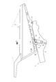
- FIG. 1 is a side view showing a dump frame 1 and body 2 in which a steady-rest structure 10 according to an embodiment of the present invention is employed.
- the frame 1 is composed of a pair of left and right side members 3 parallel to each other and a plurality of cross members that connect them, although not shown in plan view.
- front and rear refer to front and rear in the vehicle front-rear direction
- left and right refer to left and right in the vehicle width direction of the vehicle
- upper and lower refer to upper and lower in the vehicle height direction.
- the body 2 is rotatably supported on each side member 3 via a hinge pin 4 at a position slightly rearward of the center in the front-rear direction.
- the body 2 and the side member 3 are connected by a hoist cylinder 5 at a position substantially below the center of gravity G when loading (the load is indicated by a two-dot chain line in FIG. 1). By the expansion and contraction of 5, the body 2 is dumped.
- the lower surface of the body 2 is provided with vertical ribs 8 extending in the front-rear direction and a plurality of horizontal ribs 7 extending right and left so as to be orthogonal to the vertical ribs 8 at positions corresponding to the side members 3.
- a plurality (four in this embodiment) of mounts 6 corresponding to the upper surface of the side member 3 are provided on the lower surface of the vertical rib 8 along the front-rear direction (the same in the longitudinal direction) of the side member 3.
- the body 2 is seated on the frame 1 via Further, an anti-sway structure 10 according to the present invention is provided on the lower surface of the body 2 so as to correspond to a position below the gravity center position G.
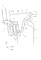
- FIG. 2 is a perspective view showing the steady rest structure 10 from obliquely below.
- the steady rest structure 10 includes a bracket 11 welded across a lower surface 7A of the lateral rib 7 extending in the left-right direction and a side surface 8A of the longitudinal rib 8 extending in the front-rear direction and orthogonal to the lateral rib 7.
- a rectangular backing plate 12 welded to the outer side surface 3 ⁇ / b> A of the member 3, a steady member 13 that is detachably bolted to the bracket 11, and the steady member 13 and the bracket 11 are interposed.
- a shim 14 is provided.
- the bracket 11 includes a pair of main plates 15 vertically suspended from the lower surface 7A of the lateral rib 7.
- the main plate 15 is formed with a main body portion 15A having a right edge welded to the body 2 and a hanging portion 15B extending downward from the main body portion 15A.
- the first closing having a bent portion in the middle of the upper and lower sides on the outer side separated from the side member 3 It is blocked by a plate 16 and is closed by an inverted L-shaped second closing plate 17 on the inner side near the side member 3. Further, on the inner side of the hanging portion 15B, the first and second closing plates 16 and 17 are closed by a rectangular thick plate-shaped mounting seat 18 having chamfered corners.
- the bracket 11 is generally welded to the lower surface of the body 2, and in the state welded to the body 2, the bracket 11 has a box shape in which the internal space is closed. The welding of the bracket 11 to the body 2 is performed on the production line of the body 2 at the factory.
- each member of the bracket 11 is joined to each other by welding, in FIG. 2 and FIGS. 3 and 4 to be referred to later, illustration of a groove portion formed for welding and a bead generated by welding is omitted. It is. The same applies to the contact plate 12 and the steadying member 13.
- the contact plate 12 is welded at a position facing the mounting seat 18 of the bracket 11 on the side surface 3A of the side member 3.
- the steady rest member 13 includes a steady rest block 21 whose outer shape is substantially similar to that of the mounting seat 18 and has a larger thickness, and a contact piece welded to the side closer to the backing plate 12 with respect to the steady rest block 21. 22.
- the shim 14 is not particularly limited.
- the shim 14 is a metal plate having a plate thickness within a range of 0.5 to 6 mm. It is interposed between the mounting seat 18 of the bracket 11 and the steadying member 13.
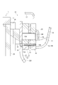
- FIG. 3 is a sectional view showing the members 12 to 14 and 18, and FIG. 4 is a perspective view showing an exploded state.
- the mounting seat 18 of the bracket 11 has a front / rear length L1 that is larger than the hanging portion 15B, and a bolt hole 18A penetrating in the thickness direction is formed at a portion protruding forward and backward from the hanging portion 15B.
- a large pin hole 18B penetrating in the thickness direction is provided at the center of the mounting seat 18.
- a C-shaped stopper 23 that covers the pin holes 18B at a predetermined interval is welded to a surface of the mounting seat 18 facing the interior of the hanging portion 15B. Such a stopper 23 prevents the pin 26 described later from falling into the bracket 11 when the pin 26 is detached from the steady member 13.
- the abutting plate 12 is fixed to the side surface 3A of the side member 3 through a frame member 24 provided so as to surround the four circumferences. That is, the frame member 24 is first welded to the side member 3, and then a predetermined amount of the contact plate 12 is fitted into the opening portion of the frame member 24, and the contact plate 12 is attached to the frame member 24 in this state. Weld.
- the contact plate 12 faces the mounting seat 18 of the bracket 11 and the center of the steady block 21 of the steady member 13, and the front and rear length L2 thereof is the front and back length of the contact piece 22 of the steady member 13.
- the vertical height H2 is substantially the same as or smaller than L3, and the vertical height H2 is smaller than the vertical height H1 of the mounting seat 18 and the steady rest block 21.
- the steadying block 21 is provided with an insertion hole 21 ⁇ / b> A corresponding to the bolt hole 18 ⁇ / b> A of the mounting seat 18.
- the entire steadying member 13 is fixed to the mounting seat 18 by bolts 25 inserted through these insertion holes 21A.
- a pin fitting hole 21B is provided in the center of the steady rest block 21, and a pin 26 having a predetermined diameter is fitted into the pin fitting hole 21B.
- the end face on the fitting end side of the pin 26 is in contact with the contact piece 22, and the contact piece 22 is provided with a weld hole penetrating in the thickness direction at a position facing the end face of the pin 26.
- the pin 26 is fixed to the contact piece 22 by plug welding through the weld hole. Such a weld hole is not shown because it is filled with a weld metal during plug welding.
- the pin 26 When the steadying member 13 is bolted to the mounting seat 18, the pin 26 is inserted into the pin hole 18B of the mounting seat 18 with little play such as a gap fit. A shearing force is applied between the steady-rest member 13 and the mounting seat 18 due to vibration during running of the dump, but the shearing force is not countered only by the four bolts 25, but the pin 26 Therefore, the steadying member 13 can be prevented from falling off.
- the steady rest block 21 is also provided with a pair of extraction taps 27 at positions where the pin 26 is sandwiched. A bolt is screwed into such a pull-out tap 27 and the screwing operation is continued even after the front end of the bolt is brought into contact with the shim 14, thereby moving the steady member 13 pin-coupled to the mounting seat 18. Can be removed easily.
- the contact piece 22 to be joined to the steady block 21 is long in the vertical direction, and both ends protrude from the steady block 21.
- the projecting portion on the lower side is a curved portion 22A that is curved outward so that the lower end side is spaced apart from the frame 1 in the left-right direction. Even when the member 13 is displaced toward the caulking plate 12, the curved portion 22 ⁇ / b> A first contacts and guides the caulking plate 12.
- the front and rear length L3 of the contact piece 22 is set to a size that does not interfere with the bolt 25, and is positioned between the front and rear bolts 25 and welded to the steady block 21.
- the abutting piece 22 is in direct proximity to and facing the abutting plate 12, and the body 2 is restrained from shaking when these abut against each other. That is, the gap dimension between the contact plate 12 and the contact piece 22 is maintained at about 0 to 3 mm.
- the hardness of the contact piece 22 is approximately the same as or slightly lower than the hardness of the contact plate 12, and by repeated contact, both members wear substantially evenly, or the contact piece 22 A little worn out. If the contact piece 22 wears faster, it is only necessary to remove and replace the steady-rest member 13 from the mounting seat 18, so that maintenance is easy.
- the contact plate 12 since the contact plate 12 has a length L2 that is substantially the same as or smaller than the contact piece 22, even if the contact piece 22 is worn, the contact plate 12 is bolted by vibration of the body 2. There is no interference with the 25 heads.
- the shim 14 is a member interposed in order to appropriately secure a gap between the contact plate 12 and the contact piece 22, and has an outer shape slightly smaller than the mounting seat 18 and the steady block 21. Yes.
- Such a shim 14 is provided with an appropriate number of sheets having an appropriate thickness when wear of the contact piece 22 or the like progresses and a predetermined gap dimension with the backing plate 12 cannot be maintained. However, it is used to ensure an appropriate gap size even in the initial stage where the contact plate 12 and the contact piece 22 are not worn at all.
- the shim 14 is provided with through holes 14A and 14B for avoiding interference with the bolt 25 and the pin 26.
- the size of the shim 14 as a whole, in particular, the front and rear length thereof is made the same as the front and rear length L3 of the abutting piece 22 to eliminate interference with the bolt 25 and at the center.
- the steadying member 13 and the shim 14 are prepared, and the shim 14 having an appropriate thickness is provided so that an appropriate gap dimension is provided between the contact plate 12 and the contact piece 22.
- a suitable number is selected, and the steadying member 13 is bolted to the mounting seat 18.
- the shim 14 can be changed or added.
- it is necessary to adjust the gap once so that the welded bead 12 and the contact piece 22 are removed and removed, and a new work is re-welded. Is unnecessary.
- the present invention is not limited to the above-described embodiment, and modifications, improvements, and the like within the scope that can achieve the object of the present invention are included in the present invention.
- the contact plate 12 is attached to the side member 3, the attachment seat 18 is provided on the bracket 11, and the steadying member 13 and the shim 14 are attached to the attachment seat 18.
- the mounting seat 18, the steady member 13, and the shim 14 may be attached to the side member 3 side, and the contact plate 12 may be provided on the bracket 11.
- the left and right pair of the steady rest structures 10 have been described.
- a plurality of the steady rest structures 10 may be provided on the left and right sides so as to be arranged side by side with a space therebetween.
- the steady-rest structure 10 is provided outside the side member 3, but the case where the steady-rest structure 10 is provided inside the side member 3 is also included in the present invention.
- the present invention can be used not only for large rigid dump trucks but also for articulated dump trucks.
- SYMBOLS 1 Frame, 2 ... Body, 3A ... Side surface, 10 ... Stabilizing structure, 11 ... Bracket, 12 ... Retaining plate, 13 ... Stabilizing member, 14 ... Shim, 18 ... Mounting seat, 22 ... Contact piece, 25 ... Bolt, 26 ... pin.
Landscapes
- Engineering & Computer Science (AREA)
- Transportation (AREA)
- Mechanical Engineering (AREA)
- Body Structure For Vehicles (AREA)
Abstract
ダンプボディの振れ止め構造(10)として、ダンプトラックのボディ(2)の下面に設けられたブラケット(11)と、ボディ(2)が回動自在に支承されるフレーム(1)の側面(3A)に設けられた当て板(12)と、当て板(12)に対して対向するブラケット(11)の対向部分に設けられた取付座(18)と、取付座(18)に着脱自在にボルト止めされる振れ止め部材(13)と、振れ止め部材(13)および取付座(18)の間に介装されるシム(14)とを備えて構成した。
Description
本発明は、ダンプボディの振れ止め構造に係り、大型ダンプトラックに用いられるボディの振れ止め構造に関する。
ダンプのボディが荷積み状態で左右に振れると、ボディの回転軸となるヒンジピンに過負荷が作用して損傷するおそれがあるうえ、乗り心地が悪くなるために、ボディの振れ止め構造が必要になる。従来、ダンプに採用されるボディの振れ止め構造としては、ボディの下面にその車幅方向に沿って一対のブラケットを取り付けた構造が知られている(例えば、特許文献1)。
このような構造によれば、各ブラケットが車体フレームの左右のサイドメンバを挟み込むように配置されているとともに、各ブラケットの垂直部がサイドメンバに設けられた当て板に近接対向するようになっており、ブラケットの垂直部が当て板に当接することで、ボディの振れが抑制される。
ブラケットは、鉛直部と当て板とを0~数mm程度の隙間が確保された状態で近接させる必要があることから、ボディをフレームに着座させた状態に組み上げた後、現場合わせにてボディの下面に溶接される。組上がり後に溶接することで、フレームやボディなどでの寸法精度に影響されることなく、所定の隙間寸法を確保することができる。
しかしながら、従来の振れ止め構造では、50kg程度となる大重量のブラケットを、隙間寸法を管理しながら現場合わせで溶接するのは大変であり、手間がかかって作業性が悪いという問題がある。一方で、現場合わせでの作業をなくし、ボディの生産ラインにてブラケットを溶接すると、寸法精度の影響により、組上がった後に適切な隙間寸法を確保できない可能性がある。
また、走行中の振動等により、垂直部および当て板の当接面が摩耗するが、その摩耗が進行して隙間が大きくなると、ヒンジピンへの負荷が大きくなるため、垂直部を形成する板材や当て板を外して交換する必要があり、溶接部分の除去や再度の溶接が必要となってメンテナンスも大変である。
本発明の目的は、作業性を向上させることができるとともに、所定の隙間寸法を確実に確保でき、かつメンテナンスも容易にできるダンプボディの振れ止め構造を提供することにある。
第1発明に係るダンプボディの振れ止め構造は、ダンプトラックのボディの下面に設けられたブラケットと、前記ボディが回動自在に支承されるフレームの側面および当該側面と対向した前記ブラケットの対向部分のうち、いずれか一方に設けられた当て板と、前記フレームの側面および前記ブラケットの対向部分のうち、いずれか他方に設けられた取付座と、前記取付座に着脱自在にボルト止めされる振れ止め部材と、前記振れ止め部材および前記取付座の間に介装されるシムとを備えていることを特徴とする。
第2発明に係るダンプボディの振れ止め構造では、前記振れ止め部材と前記取付座とにわたって挿通されたピンを備えていることを特徴とする。
第3発明に係るダンプボディの振れ止め構造では、前記振れ止め部材は、前記当て板に当接される当接片を備えるとともに、該当接片の前後位置で挿通されるボルトにより前記取付座にボルト止めされ、前記当て板の前後長さは、前記当接片の前後長さと略同じか、または前記当接片の前後長さよりも小さいことを特徴とする。
第1発明によれば、互いに対向することになる取付座と当て板との間には、振れ止め部材およびシムを取り付けるための間隔が存在するため、それらの取付座または当て板が設けられるブラケットを、作業環境が整った生産ラインにて予めボディに溶接しても、寸法精度に影響されずボディをフレームに支障なく組み付けることができる。従って、隙間寸法を管理しながら大重量のブラケットを現場作業にて溶接しなくともよく、作業性を大幅に向上させることができる。
また、当接片や当て板が摩耗した場合だけでなく、組み立て直後であっても、シムの追加や変更等により、両者間の隙間寸法を容易に調節できるから、所定の隙間寸法を確実に確保できる。
さらに、摩耗への対応については、シムの変更や追加、あるいは振れ止め部材を着脱させて新たなものと交換すればよく、従来とは異なって現場にて当て板等の溶接を外したり、新たな当て板を再度溶接によって取り付けたりする必要がなく、メンテナンスを容易にできる。
さらに、摩耗への対応については、シムの変更や追加、あるいは振れ止め部材を着脱させて新たなものと交換すればよく、従来とは異なって現場にて当て板等の溶接を外したり、新たな当て板を再度溶接によって取り付けたりする必要がなく、メンテナンスを容易にできる。
第2発明によれば、ダンプの走行中に生じる振れ止め部材と取付座との間の剪断力を、ボルトのみではなくピンによっても対抗できるので、振れ止め部材の取り付け強度を向上させることができ、振れ止め部材の脱落等を確実に防止できる。
第3発明によれば、当接片の前後にボルトの頭部が位置し、当て板の前後長さが当接片の前後長さと略同じか小さいので、当接片の摩耗が進行しても、当接片の当て板への当接時には、ボルト頭部が当て板にぶつかる心配がなく、ボルト等部の破損等を防止できる。
以下、本発明の実施形態を図面に基づいて説明する。
図1は、本発明の一実施形態に係る振れ止め構造10が採用されたダンプのフレーム1およびボディ2を示す側面図である。
図1において、フレーム1は、平面視での図示を省略するが、平行な左右一対のサイドメンバ3、およびこれらを連結する複数のクロスメンバ等により構成されている。なお、以下の説明において、前後とは車両の前後方向での前後をいい、左右とは車両の車幅方向での左右をいい、上下とは車両の高さ方向での上下をいう。
図1は、本発明の一実施形態に係る振れ止め構造10が採用されたダンプのフレーム1およびボディ2を示す側面図である。
図1において、フレーム1は、平面視での図示を省略するが、平行な左右一対のサイドメンバ3、およびこれらを連結する複数のクロスメンバ等により構成されている。なお、以下の説明において、前後とは車両の前後方向での前後をいい、左右とは車両の車幅方向での左右をいい、上下とは車両の高さ方向での上下をいう。
ボディ2は、前後方向の中央よりもやや後方側の部位にて、各サイドメンバ3にヒンジピン4を介して回動自在に支承されている。側面視において、荷積み時(図1に積荷を2点鎖線で示した)の重心位置Gの概略下方位置では、ボディ2とサイドメンバ3とがホイストシリンダ5にて連結されており、ホイストシリンダ5の伸縮により、ボディ2のダンプ動作が行われる。
ボディ2の下面には、各サイドメンバ3に対応する位置に、前後に延びる縦リブ8と、縦リブ8に直交するように左右に延びる複数の横リブ7が設けられている。縦リブ8の下面には、サイドメンバ3の上面に対応したマウント6がサイドメンバ3の前後方向(長手方向に同じ)に沿って複数(本実施形態では4つ)設けられ、これらのマウント6を介してボディ2がフレーム1に着座している。また、ボディ2の下面には、重心位置Gの下方に対応して、本発明に係る振れ止め構造10が設けられている。
図2は、振れ止め構造10を斜め下方から示す斜視図である。
図2において、振れ止め構造10は、左右に延びた横リブ7の下面7Aおよび前後に延びて前記横リブ7と直交する縦リブ8の側面8Aとに跨って溶接されたブラケット11と、サイドメンバ3の外方側の側面3Aに溶接された矩形の当て板12と、ブラケット11に着脱自在にボルト止めされる振れ止め部材13と、振れ止め部材13およびブラケット11の間に介装されるシム14を備えている。
図2において、振れ止め構造10は、左右に延びた横リブ7の下面7Aおよび前後に延びて前記横リブ7と直交する縦リブ8の側面8Aとに跨って溶接されたブラケット11と、サイドメンバ3の外方側の側面3Aに溶接された矩形の当て板12と、ブラケット11に着脱自在にボルト止めされる振れ止め部材13と、振れ止め部材13およびブラケット11の間に介装されるシム14を備えている。
ブラケット11は、横リブ7の下面7Aに鉛直に垂設された一対のメインプレート15を備えている。メインプレート15には、ボディ2に溶接される直角な辺縁を有した本体部15Aと、本体部15Aから下方に延設された垂下部15Bとが形成されている。
前後に所定間隔を空けて対向し合う本体部15A同士の間、および垂下部15B同士の間は、サイドメンバ3から離間した外方側では、上下の途中に折曲部分を有した第1閉塞プレート16で塞がれ、サイドメンバ3に近い内方側では、逆L字形状の第2閉塞プレート17で塞がれている。また、垂下部15Bの内方側において、第1、第2閉塞プレート16,17の間は、四隅に面取りが施された矩形で厚板状の取付座18によって塞がれている。
従って、ブラケット11は総じて、ボディ2の下面に溶接されているのであって、ボディ2に溶接された状態では、内部空間が閉じられた箱状とされている。このようなブラケット11のボディ2への溶接は、工場でのボディ2の生産ラインで行われる。
なお、ブラケット11の各部材は、互いに溶接によって接合されているが、図2および後に参照する図3、図4では、溶接用に形成される開先部分や、溶接によって生じるビードの図示を省略してある。当て板12および振れ止め部材13においても同様である。
当て板12は、サイドメンバ3の側面3Aにおいて、ブラケット11の取付座18に対して互いに対向する位置に溶接されている。
振れ止め部材13は、外形形状が取付座18と略類似した形状で厚さがより厚い振れ止めブロック21と、振れ止めブロック21に対して当て板12と近接する側に溶接された当接片22とを備えている。
シム14は、特に限定されるものではないが、例えば0.5~6mmの範囲での板厚寸法を有した金属板であり、板厚寸法の異なるものが複数種類用意され、適宜な枚数がブラケット11の取付座18と振れ止め部材13との間に介装される。
以下には、図3、図4に基づき、ブラケット11の取付座18、当て板12、振れ止め部材13、およびシム14について詳説する。図3は、それらの部材12~14,18を示す断面図、図4は、分解状態を示す斜視図である。
図3、図4において、ブラケット11の取付座18は、垂下部15Bよりも大きい前後長さL1を有し、垂下部15Bから前後にはみ出した部分には、厚さ方向に貫通したボルト孔18Aが略四隅に対応して設けられている。取付座18の中央には、厚さ方向に貫通した大きなピン孔18Bが設けられている。この取付座18において、垂下部15Bの内部に臨む面には、ピン孔18Bを所定間隔空けて覆うC字形状のストッパ23が溶接されている。このようなストッパ23は、後述するピン26が振れ止め部材13から外れた場合に、ブラケット11の内部に落下するのを防止する。
当て板12は、その四周を囲むように設けられた枠部材24を介してサイドメンバ3の側面3Aに固定されている。すなわち、サイドメンバ3には先ず、枠部材24を溶接しておき、次いで、枠部材24の開口部分に当て板12を所定量嵌め込んだ状態にし、この状態で当て板12を枠部材24に溶接する。当て板12は、ブラケット11の取付座18や、振れ止め部材13の振れ止めブロック21の中央に対向しており、その前後長さL2は、振れ止め部材13の当接片22の前後長さL3と略同じか、またはそれよりも小さく、上下高さH2は取付座18および振れ止めブロック21の上下高さH1よりも小さい。
振れ止め部材13において、振れ止めブロック21には、取付座18のボルト孔18Aに対応した挿通孔21Aが設けられている。これらの挿通孔21Aに挿通されるボルト25により、振れ止め部材13全体が取付座18に固定される。振れ止めブロック21の中央には、ピン嵌合孔21Bが設けられ、ピン嵌合孔21Bには、所定の径寸法を有したピン26が嵌合している。ここで、ピン26の嵌合端側の端面は当接片22に当接されているとともに、当接片22にはピン26の端面と対向した位置に厚さ方向に貫通した溶接孔が設けられ、この溶接孔を通した栓溶接によりピン26が当接片22に固定されている。そのような溶接孔は、栓溶接時の溶着金属により埋められるため、図示されていない。
このピン26は振れ止め部材13が取付座18にボルト止めされるとき、取付座18のピン孔18Bに隙間嵌め程度のガタの少ない状態で挿入される。振れ止め部材13と取付座18との間には、ダンプの走行中の振動等により剪断力が作用するが、そのような剪断力を4本のボルト25のみで対抗するのではなく、ピン26によっても対抗でき、振れ止め部材13の脱落等を防止できる。
振れ止めブロック21にはまた、ピン26を挟む位置に一対の抜きタップ27が設けられている。このような抜きタップ27にボルトを螺入し、ボルトの先端をシム14に当接させた後にも螺入操作を続けることで、取付座18に対してピン結合された振れ止め部材13を移動させることができ、取り外しを容易にできる。
このような振れ止めブロック21に接合される当接片22は、上下方向に長く、両端が振れ止めブロック21よりも突出している。特に下方側の突出部分は、下端側がフレーム1に対して左右方向に離間するように外方に湾曲した湾曲部22Aになっており、ボディ2が上方から傾倒して着座する際に、振れ止め部材13が当て板12側にずれている場合でも、湾曲部22Aが当て板12に最初に接触してガイドするようになっている。
このような当接片22の前後長さL3は、ボルト25と干渉しない大きさに設定され、前後のボルト25間に位置して振れ止めブロック21に溶接されている。そして、当接片22が当て板12に対して直接的に近接対向しているのであり、これらが互いに当接することでボディ2の揺れが抑制される。つまり、当て板12と当接片22との間の隙間寸法が、0~3mm程度に維持されているのである。
そして、当接片22の硬度は、当て板12の硬度と同程度か、やや低い硬度になっており、当接を繰り返すことで、両部材が略均等に摩耗するか、または当接片22がやや多く摩耗する。当接片22が早く摩耗する方が、振れ止め部材13を取付座18から外して交換するだけでよいので、メンテナンスが容易である。また、当て板12は、当接片22と略同じか、または小さい前後長さL2を有していることで、当接片22が摩耗しても、ボディ2の振動によって当て板12がボルト25の頭部と干渉することはない。
シム14は、当て板12と当接片22との隙間を適正に確保するために介装される部材であって、取付座18や振れ止めブロック21よりも僅かに小さい外形形状を有している。このようなシム14は、当接片22等の摩耗が進行し、当て板12との所定の隙間寸法を維持できなくなった場合に、適宜な厚さのものが適宜な枚数で介装されるが、その他、当て板12および当接片22が全く摩耗していない初期の段階でも、適正な隙間寸法を確保するために用いられる。
シム14には、ボルト25およびピン26との干渉を避けるための貫通孔14A、14Bが設けられている。ただし、貫通孔14A,14Bを設ける代わりに、シム14全体の大きさ、特にその前後長さを当接片22の前後長さL3と同程度にしてボルト25との干渉をなくすとともに、中央には上方に開口したU字形状の切欠開口を設けてピン26との干渉を避けるようにしてもよい。このような形状にすることで、振れ止め部材13を取付座18から完全に取り外すことなく多少ずらすだけで、シム14全体を下方から上方に向けて介装できる。
以上に説明した振れ止め構造10によれば、ブラケット11のボディ2への溶接や、当て板12のサイドメンバ3への溶接を、工場等の管理された作業環境下にある生産ラインにて行っておく。フレーム1へのボディ2の組上がり時については、ブラケット11の取付座18と当て板12との間には、振れ止め部材13および所定の厚みを想定したシム14を取り付けるだけの十分な間隔が空いているため、この間隔で寸法精度を十分に吸収でき、組み付けができない事態を回避できる。
フレーム1にボディ2を組み付けた後、振れ止め部材13およびシム14を用意し、当て板12と当接片22との間が適正な隙間寸法になるように、適宜な板厚寸法のシム14を適宜な枚数選択して介装し、振れ止め部材13を取付座18にボルト止めする。また、ダンプの使用により当接片22が摩耗して隙間の調整が必要な場合には、当接片22が使用可能な許容範囲内にあれば、シム14の変更や追加等で対応すればよく、従来とは異なり、一度隙間調整が必要になったからといって、溶接された当て板12や当接片22の溶接ビードを除去して取り外し、新たなものを再度溶接するといった大掛かりな作業は不要である。
なお、本発明は前述の実施形態に限定されるものではなく、本発明の目的を達成できる範囲での変形、改良等は本発明に含まれるものである。
例えば、前記実施形態では、当て板12がサイドメンバ3に取り付けられ、取付座18がブラケット11に設けられ、この取付座18に対して振れ止め部材13およびシム14が取り付けられていたが、図5に示すように、そのような取付座18や、振れ止め部材13、シム14をサイドメンバ3側に取り付け、当て板12をブラケット11に設けてもよい。
例えば、前記実施形態では、当て板12がサイドメンバ3に取り付けられ、取付座18がブラケット11に設けられ、この取付座18に対して振れ止め部材13およびシム14が取り付けられていたが、図5に示すように、そのような取付座18や、振れ止め部材13、シム14をサイドメンバ3側に取り付け、当て板12をブラケット11に設けてもよい。
前記実施形態では、振れ止め構造10を車両の左右一対設けた例で説明したが、前後に間隔を空けて並設されるように、左右にそれぞれ複数設けてもよい。
前記実施形態では、振れ止め構造10がサイドメンバ3の外側に設けられていたが、サイドメンバ3の内側に設けられる場合でも、本発明に含まれる。
前記実施形態では、振れ止め構造10がサイドメンバ3の外側に設けられていたが、サイドメンバ3の内側に設けられる場合でも、本発明に含まれる。
本発明は、大型のリジットタイプのダンプトラックに利用できる他、アーティキュレートタイプのダンプトラックにも利用できる。
1…フレーム、2…ボディ、3A…側面、10…振れ止め構造、11…ブラケット、12…当て板、13…振れ止め部材、14…シム、18…取付座、22…当接片、25…ボルト、26…ピン。
Claims (3)
- ダンプトラックのボディの下面に設けられたブラケットと、
前記ボディが回動自在に支承されるフレームの側面および当該側面と対向した前記ブラケットの対向部分のうち、いずれか一方に設けられた当て板と、
前記フレームの側面および前記ブラケットの対向部分のうち、いずれか他方に設けられた取付座と、
前記取付座に着脱自在にボルト止めされる振れ止め部材と、
前記振れ止め部材および前記取付座の間に介装されるシムとを備えている
ことを特徴とするダンプボディの振れ止め構造。 - 請求項1に記載のダンプボディの振れ止め構造において、
前記振れ止め部材と前記取付座とにわたって挿通されたピンを備えている
ことを特徴とするダンプボディの振れ止め構造。 - 請求項1または請求項2に記載のダンプボディの振れ止め構造において、
前記振れ止め部材は、前記当て板に当接される当接片を備えるとともに、該当接片の前後位置で挿通されるボルトにより前記取付座にボルト止めされ、
前記当て板の前後長さは、前記当接片の前後長さと略同じか、または前記当接片の前後長さよりも小さい
ことを特徴とするダンプボディの振れ止め構造。
Applications Claiming Priority (2)
| Application Number | Priority Date | Filing Date | Title |
|---|---|---|---|
| JP2011-215401 | 2011-09-29 | ||
| JP2011215401A JP2013075560A (ja) | 2011-09-29 | 2011-09-29 | ダンプボディの振れ止め構造 |
Publications (1)
| Publication Number | Publication Date |
|---|---|
| WO2013046741A1 true WO2013046741A1 (ja) | 2013-04-04 |
Family
ID=47994813
Family Applications (1)
| Application Number | Title | Priority Date | Filing Date |
|---|---|---|---|
| PCT/JP2012/053501 Ceased WO2013046741A1 (ja) | 2011-09-29 | 2012-02-15 | ダンプボディの振れ止め構造 |
Country Status (2)
| Country | Link |
|---|---|
| JP (1) | JP2013075560A (ja) |
| WO (1) | WO2013046741A1 (ja) |
Families Citing this family (1)
| Publication number | Priority date | Publication date | Assignee | Title |
|---|---|---|---|---|
| JP2016124375A (ja) * | 2014-12-26 | 2016-07-11 | いすゞ自動車株式会社 | Vロッドの連結構造 |
Citations (5)
| Publication number | Priority date | Publication date | Assignee | Title |
|---|---|---|---|---|
| JPS5713338U (ja) * | 1980-06-30 | 1982-01-23 | ||
| JPS57107644U (ja) * | 1980-12-25 | 1982-07-02 | ||
| JPH0549481U (ja) * | 1991-12-12 | 1993-06-29 | 株式会社小松製作所 | ダンプトラックのボデイ振れ止め装置 |
| JPH06914U (ja) * | 1992-06-12 | 1994-01-11 | 株式会社小松製作所 | ダンプトラックのボディ振れ止め装置 |
| JP2006015235A (ja) * | 2004-07-01 | 2006-01-19 | Nordson Corp | スロットダイ、多孔質材料に液体を充填する方法、多孔質木製板の縁部を処理する方法、チップボード及びパーチクルボード |
-
2011
- 2011-09-29 JP JP2011215401A patent/JP2013075560A/ja not_active Withdrawn
-
2012
- 2012-02-15 WO PCT/JP2012/053501 patent/WO2013046741A1/ja not_active Ceased
Patent Citations (5)
| Publication number | Priority date | Publication date | Assignee | Title |
|---|---|---|---|---|
| JPS5713338U (ja) * | 1980-06-30 | 1982-01-23 | ||
| JPS57107644U (ja) * | 1980-12-25 | 1982-07-02 | ||
| JPH0549481U (ja) * | 1991-12-12 | 1993-06-29 | 株式会社小松製作所 | ダンプトラックのボデイ振れ止め装置 |
| JPH06914U (ja) * | 1992-06-12 | 1994-01-11 | 株式会社小松製作所 | ダンプトラックのボディ振れ止め装置 |
| JP2006015235A (ja) * | 2004-07-01 | 2006-01-19 | Nordson Corp | スロットダイ、多孔質材料に液体を充填する方法、多孔質木製板の縁部を処理する方法、チップボード及びパーチクルボード |
Also Published As
| Publication number | Publication date |
|---|---|
| JP2013075560A (ja) | 2013-04-25 |
Similar Documents
| Publication | Publication Date | Title |
|---|---|---|
| US20090085377A1 (en) | Structure and a system for connecting a machine cab to a supporting frame | |
| JP5043861B2 (ja) | 作業機械のキャブ支持装置 | |
| JP4766517B2 (ja) | 自動車の下部構造 | |
| CN111448127B (zh) | 用于将上部车辆部分与基部车辆部分可释放地接合的组件 | |
| CN108699807A (zh) | 工程机械 | |
| CN100415555C (zh) | 发动机支架结构 | |
| EP3307578A1 (fr) | Traverse en aluminium extrudé et à zones longitudinales pleines, pour la suspension d'une machine électrique motrice d'un véhicule | |
| US20100253056A1 (en) | Supporting traverse | |
| KR20090077382A (ko) | 사이드미러 고정수단이 구비된 중장비 | |
| JP2013075560A (ja) | ダンプボディの振れ止め構造 | |
| JP4161788B2 (ja) | 産業車両のアクスル支持構造、および、産業車両 | |
| JP5991019B2 (ja) | 建設機械 | |
| JP6915952B2 (ja) | 作業機械 | |
| JP2010202057A (ja) | セミクローラ型作業車両 | |
| JP4851603B2 (ja) | 建設機械 | |
| JP2016037171A (ja) | 車両用サブフレーム | |
| JP2008149888A (ja) | パワープラントの支持構造 | |
| JP6617020B2 (ja) | 建設機械のキャブ | |
| JP6307982B2 (ja) | 配管中継構造 | |
| JP3056716B2 (ja) | 建設機械のメインフレーム | |
| JP5431103B2 (ja) | 建設機械のカウンタウェイト、カウンタウェイトユニット及びカウンタウェイト取付構造 | |
| JP6689767B2 (ja) | 装軌式車両 | |
| JP2011131616A (ja) | 荷台の下部構造 | |
| JP5916375B2 (ja) | リアアクスル支持構造 | |
| JP6339948B2 (ja) | ショベル |
Legal Events
| Date | Code | Title | Description |
|---|---|---|---|
| 121 | Ep: the epo has been informed by wipo that ep was designated in this application |
Ref document number: 12837245 Country of ref document: EP Kind code of ref document: A1 |
|
| NENP | Non-entry into the national phase |
Ref country code: DE |
|
| 122 | Ep: pct application non-entry in european phase |
Ref document number: 12837245 Country of ref document: EP Kind code of ref document: A1 |