WO2013038833A1 - 画像処理システム、画像処理方法および画像処理プログラム - Google Patents
画像処理システム、画像処理方法および画像処理プログラム Download PDFInfo
- Publication number
- WO2013038833A1 WO2013038833A1 PCT/JP2012/069809 JP2012069809W WO2013038833A1 WO 2013038833 A1 WO2013038833 A1 WO 2013038833A1 JP 2012069809 W JP2012069809 W JP 2012069809W WO 2013038833 A1 WO2013038833 A1 WO 2013038833A1
- Authority
- WO
- WIPO (PCT)
- Prior art keywords
- image
- distance
- input image
- unit
- image processing
- Prior art date
Links
Images


Classifications
-
- H—ELECTRICITY
- H04—ELECTRIC COMMUNICATION TECHNIQUE
- H04N—PICTORIAL COMMUNICATION, e.g. TELEVISION
- H04N13/00—Stereoscopic video systems; Multi-view video systems; Details thereof
- H04N13/10—Processing, recording or transmission of stereoscopic or multi-view image signals
- H04N13/106—Processing image signals
- H04N13/122—Improving the 3D impression of stereoscopic images by modifying image signal contents, e.g. by filtering or adding monoscopic depth cues
-
- G—PHYSICS
- G01—MEASURING; TESTING
- G01B—MEASURING LENGTH, THICKNESS OR SIMILAR LINEAR DIMENSIONS; MEASURING ANGLES; MEASURING AREAS; MEASURING IRREGULARITIES OF SURFACES OR CONTOURS
- G01B11/00—Measuring arrangements characterised by the use of optical techniques
- G01B11/02—Measuring arrangements characterised by the use of optical techniques for measuring length, width or thickness
-
- G—PHYSICS
- G01—MEASURING; TESTING
- G01B—MEASURING LENGTH, THICKNESS OR SIMILAR LINEAR DIMENSIONS; MEASURING ANGLES; MEASURING AREAS; MEASURING IRREGULARITIES OF SURFACES OR CONTOURS
- G01B11/00—Measuring arrangements characterised by the use of optical techniques
- G01B11/24—Measuring arrangements characterised by the use of optical techniques for measuring contours or curvatures
-
- G—PHYSICS
- G06—COMPUTING; CALCULATING OR COUNTING
- G06T—IMAGE DATA PROCESSING OR GENERATION, IN GENERAL
- G06T7/00—Image analysis
- G06T7/50—Depth or shape recovery
- G06T7/55—Depth or shape recovery from multiple images
- G06T7/593—Depth or shape recovery from multiple images from stereo images
-
- G—PHYSICS
- G06—COMPUTING; CALCULATING OR COUNTING
- G06T—IMAGE DATA PROCESSING OR GENERATION, IN GENERAL
- G06T7/00—Image analysis
- G06T7/97—Determining parameters from multiple pictures
-
- H—ELECTRICITY
- H04—ELECTRIC COMMUNICATION TECHNIQUE
- H04N—PICTORIAL COMMUNICATION, e.g. TELEVISION
- H04N13/00—Stereoscopic video systems; Multi-view video systems; Details thereof
- H04N13/10—Processing, recording or transmission of stereoscopic or multi-view image signals
- H04N13/106—Processing image signals
- H04N13/144—Processing image signals for flicker reduction
-
- H—ELECTRICITY
- H04—ELECTRIC COMMUNICATION TECHNIQUE
- H04N—PICTORIAL COMMUNICATION, e.g. TELEVISION
- H04N13/00—Stereoscopic video systems; Multi-view video systems; Details thereof
- H04N13/20—Image signal generators
- H04N13/204—Image signal generators using stereoscopic image cameras
- H04N13/239—Image signal generators using stereoscopic image cameras using two 2D image sensors having a relative position equal to or related to the interocular distance
-
- G—PHYSICS
- G06—COMPUTING; CALCULATING OR COUNTING
- G06T—IMAGE DATA PROCESSING OR GENERATION, IN GENERAL
- G06T2207/00—Indexing scheme for image analysis or image enhancement
- G06T2207/10—Image acquisition modality
- G06T2207/10004—Still image; Photographic image
- G06T2207/10012—Stereo images
-
- G—PHYSICS
- G06—COMPUTING; CALCULATING OR COUNTING
- G06T—IMAGE DATA PROCESSING OR GENERATION, IN GENERAL
- G06T2207/00—Indexing scheme for image analysis or image enhancement
- G06T2207/20—Special algorithmic details
- G06T2207/20021—Dividing image into blocks, subimages or windows
-
- G—PHYSICS
- G06—COMPUTING; CALCULATING OR COUNTING
- G06T—IMAGE DATA PROCESSING OR GENERATION, IN GENERAL
- G06T2207/00—Indexing scheme for image analysis or image enhancement
- G06T2207/20—Special algorithmic details
- G06T2207/20048—Transform domain processing
- G06T2207/20061—Hough transform
-
- H—ELECTRICITY
- H04—ELECTRIC COMMUNICATION TECHNIQUE
- H04N—PICTORIAL COMMUNICATION, e.g. TELEVISION
- H04N13/00—Stereoscopic video systems; Multi-view video systems; Details thereof
- H04N2013/0074—Stereoscopic image analysis
- H04N2013/0081—Depth or disparity estimation from stereoscopic image signals
-
- H—ELECTRICITY
- H04—ELECTRIC COMMUNICATION TECHNIQUE
- H04N—PICTORIAL COMMUNICATION, e.g. TELEVISION
- H04N13/00—Stereoscopic video systems; Multi-view video systems; Details thereof
- H04N2013/0074—Stereoscopic image analysis
- H04N2013/0085—Motion estimation from stereoscopic image signals
Definitions
- the present invention relates to an image processing system, an image processing method, and an image processing program directed to image generation for stereoscopically displaying a subject.
- Patent Document 1 a plurality of image information is acquired by imaging a subject from different positions by a plurality of imaging units, and SAD (Sum of Absolute Difference).
- the correlation degree of the image information is calculated by performing a correlation calculation by an arithmetic method, an SSD (Sum of Squared Difference) calculation method, or the like.
- a parallax value for the subject is calculated based on the calculated degree of correlation, and a distance image is generated by calculating the position (distance value) of the subject from the parallax value.
- Patent Document 1 discloses a method for generating a highly reliable distance image by obtaining a high-precision calculation result in sub-pixel level calculation while reducing processing time. A configuration is disclosed.
- the image may be distorted. Due to such distortion, for example, when an object having a linear structure is included in the subject, the user already knows the shape of the artifact, and thus the generated distortion is conspicuous. There is. Such distortion occurs when a corresponding point between two images when calculating a parallax value for the subject cannot be searched correctly, or when the subject includes a region where the distance from the imaging unit varies greatly. obtain.
- an object of the present invention is to provide an image processing system, an image processing method, and an image suitable for stereoscopic display with a sharp feeling while suppressing image distortion. It is to provide a processing program.
- An image processing system includes: a first imaging unit that captures a subject and obtains a first input image; and a second input that captures the subject from a different viewpoint from the first imaging unit.
- Distance information indicating a distance with respect to a predetermined position for each unit region having a predetermined pixel size between the second imaging means for acquiring an image and the first input image and the second input image.
- Distance information acquisition means for acquiring.
- the unit region is defined by a first pixel interval corresponding to the first direction in the first input image and a second pixel interval different from the first pixel interval corresponding to the second direction.
- the image processing system includes a stereoscopic generation unit configured to generate a stereoscopic image for stereoscopically displaying the subject by shifting the pixels included in the first input image in the first direction based on the distance information. Further, the first pixel interval that defines the unit area is shorter than the second pixel interval.
- the image processing system further includes a smoothing processing unit that performs a smoothing process on the distance image indicating the distance information in accordance with the directionality of the pixel size of the unit area.
- the image processing system further includes a region determination unit that determines a feature region included in the subject, and the distance information acquisition unit changes the pixel size of the unit region including the extracted feature region.
- the feature region includes any of a straight line, a quadratic curve, a circle, an ellipse, and a texture.
- the feature region includes a near and far conflict region that is a region having a relatively large distance variation.
- the distance information acquisition unit acquires distance information based on a correspondence relationship between each point of the subject between the first input image and the second input image.
- An image processing method includes a step of capturing a subject to acquire a first input image, and capturing a subject from a viewpoint different from the viewpoint from which the first input image is captured.
- a step of acquiring an input image and a step of acquiring distance information indicating a distance with a predetermined position as a reference for each unit region having a predetermined pixel size between the first input image and the second input image.
- the unit region is defined by a first pixel interval corresponding to the first direction in the first input image and a second pixel interval different from the first pixel interval corresponding to the second direction.
- An image processing program causes a computer to execute image processing.
- the image processing program acquires, in a computer, a first input image obtained by imaging a subject, and a second input image obtained by imaging the subject from a viewpoint different from the viewpoint obtained by imaging the first input image. And obtaining distance information indicating a distance with a predetermined position as a reference for each unit region having a predetermined pixel size between the first input image and the second input image.
- the unit region is defined by a first pixel interval corresponding to the first direction in the first input image and a second pixel interval different from the first pixel interval corresponding to the second direction.
- FIG. 1 is a block diagram showing a basic configuration of an image processing system according to an embodiment of the present invention. It is a figure which shows the specific structural example of the imaging part shown in FIG. It is a block diagram which shows the structure of the digital camera which actualized the image processing system shown in FIG. It is a block diagram which shows the structure of the personal computer which actualized the image processing system shown in FIG. It is a schematic block diagram which shows the procedure of the image processing method relevant to this invention. It is a figure which shows the example of a pair of input image imaged by the imaging part shown in FIG. It is a figure which shows the example of the distance image produced
- step S2 It is a figure which shows an example of the averaging filter used in the smoothing process (step S2) of FIG. It is a figure which shows the result of having performed the smoothing process with respect to the distance image shown in FIG. It is a figure for demonstrating the process sequence in the stereo image generation process (step S3) of FIG. It is a flowchart which shows the process sequence of the stereo image generation process shown in FIG. It is a figure which shows an example of the stereo image produced
- the image processing system generates a stereo image for performing stereoscopic display from a plurality of input images obtained by imaging a subject from a plurality of viewpoints.
- distance information is acquired for each unit region having a predetermined pixel size between two input images. Then, a stereo image is generated from the acquired distance information of each point.
- FIG. 1 is a block diagram showing a basic configuration of an image processing system 1 according to the embodiment of the present invention.
- the image processing system 1 includes an imaging unit 2, an image processing unit 3, and a 3D image output unit 4.
- the imaging unit 2 captures a subject to acquire a pair of input images (input image 1 and input image 2), and the image processing unit 3 acquires the acquired pair of inputs.
- a stereo image (right-eye image and left-eye image) for stereoscopic display of the subject is generated.
- the 3D image output unit 4 outputs the stereo image (right eye image and left eye image) to a display device or the like.
- the imaging unit 2 captures the same object (subject) from different viewpoints and generates a pair of input images. More specifically, the imaging unit 2 is connected to the first camera 21, the second camera 22, an A / D (Analog to Digital) conversion unit 23 connected to the first camera, and the second camera 22. A / D converter 24. The A / D conversion unit 23 outputs an input image 1 indicating the subject imaged by the first camera 21, and the A / D conversion unit 24 outputs an input image 2 indicating the subject imaged by the second camera 22. To do.
- the first camera 21 and the A / D conversion unit 23 correspond to a first imaging unit that captures a subject and obtains a first input image.
- the second camera 22 and the A / D conversion unit 24 This corresponds to a second imaging unit that captures a subject from a different viewpoint from the first imaging unit and obtains a second input image.
- the first camera 21 includes a lens 21a that is an optical system for imaging a subject, and an imaging device 21b that is a device that converts light collected by the lens 21a into an electrical signal.
- the A / D converter 23 converts a video signal (analog electrical signal) indicating a subject output from the image sensor 21b into a digital signal and outputs the digital signal.
- the second camera 22 includes a lens 22a that is an optical system for imaging a subject, and an imaging element 22b that is a device that converts light collected by the lens 22a into an electrical signal.
- the A / D converter 24 converts a video signal (analog electrical signal) indicating a subject output from the image sensor 22b into a digital signal and outputs the digital signal.
- the imaging unit 2 may further include a control processing circuit for controlling each part.
- a stereo image (right-eye image and left-eye image) can be generated using an input image captured by one camera. Therefore, if a corresponding point search process for generating a distance image as will be described later can be executed, functions and performance (typically, pixels of the acquired input image) between the first camera 21 and the second camera 22. Size etc.) need not be the same.
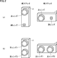
- FIG. 2 is a diagram illustrating a specific configuration example of the imaging unit 2 illustrated in FIG.
- An example of the imaging unit 2 shown in FIG. 2A has a configuration in which a main lens with an optical zoom function and a sub lens without an optical zoom function are combined.
- the example of the imaging unit 2 shown in FIG. 2B has a configuration in which two main lenses with an optical zoom function are combined.
- the imaging unit 2 In the image processing method according to the present embodiment, it is only necessary that the line-of-sight directions (viewpoints) of the respective cameras with respect to the same subject are different. Therefore, in the imaging unit 2, the arrangement of the main lens and the sub lens (vertical arrangement or The horizontal arrangement) can be arbitrarily set. That is, the imaging unit 2 shown in FIG. 2A or 2B may be arranged in the vertically long direction, or may be arranged in the horizontally long direction.
- the imaging example (image example) described later is obtained in a configuration in which two lenses of the same type (without the optical zoom function) are arranged at a predetermined interval in the vertical direction.
- the input image 1 and the input image 2 it is not always necessary to obtain the input image 1 and the input image 2 with consent. That is, if the positional relationship of the imaging unit 2 with respect to the subject is substantially the same at the imaging timing for acquiring the input image 1 and the input image 2, the input image 1 and the input image 2 are acquired at different timings, respectively. Also good.
- a stereo image for performing stereoscopic display can be generated not only as a still image but also as a moving image. In this case, a series of images can be acquired for each camera by capturing the subject continuously in time while synchronizing between the first camera 21 and the second camera 22.
- the input image may be a color image or a monochrome image.
- the image processing unit 3 performs stereoscopic display of the subject by performing the image processing method according to the present embodiment on the pair of input images acquired by the imaging unit 2. Stereo images (right eye image and left eye image) are generated. More specifically, the image processing unit 3 includes a corresponding point search unit 30, a distance image generation unit 32, an area determination unit 34, a smoothing processing unit 36, and a 3D image generation unit 38.
- Corresponding point search unit 30 performs corresponding point search processing on a pair of input images (input image 1 and input image 2).
- the corresponding point search processing includes a POC (Phase-Only Correlation) operation method, a SAD (Sum of Absolute Difference) operation method, an SSD (Sum of Squared Difference) operation method, and an NCC (NormalizedCreationCreation) operation method.
- POC Phase-Only Correlation
- SAD Sud of Absolute Difference
- SSD Small of Squared Difference
- NCC NormalizedCreationCreation
- the distance image generation unit 32 acquires distance information about two input images. This distance information is calculated based on the difference in information about the same subject. Typically, the distance image generation unit 32 calculates distance information from a correspondence relationship between input images for each point of the subject searched by the corresponding point search unit 30.
- the imaging unit 2 images the subject from different viewpoints. Therefore, between two input images, pixels expressing a certain point (attention point) of the subject are shifted by a distance corresponding to the distance between the imaging unit 2 and the point of the subject.
- the difference between the coordinates on the image coordinate system of the pixel corresponding to the target point of the input image 1 and the coordinates on the image coordinate system of the pixel corresponding to the target point of the input image 2 is referred to as “parallax”. Called.
- the distance image generation unit 32 calculates the parallax for each point of interest of the subject searched by the corresponding point search unit 30.
- This parallax is an index value indicating the distance from the imaging unit 2 to the corresponding point of interest of the subject.
- distance information is used as a general term for the parallax and the distance from the imaging unit 2 of each point of the subject indicated by the parallax.
- the direction in which the parallax occurs between the input images depends on the positional relationship between the first camera 21 and the second camera 22 in the imaging unit 2. For example, when the first camera 21 and the second camera 22 are arranged at a predetermined interval in the vertical direction, the parallax between the input image 1 and the input image 2 is generated in the vertical direction.
- the distance image generation unit 32 calculates distance information about each point of the subject, and generates a distance image (parallax image) that expresses the calculated distance information in association with coordinates on the image coordinate system. An example of this distance image will be described later.
- the corresponding point search unit 30 Since the corresponding point search unit 30 performs a corresponding point search for each unit region having a predetermined pixel size, the distance image is originally generated as an image having one unit region as one pixel. .
- the imaging unit 2 is arranged for each unit region having a predetermined pixel size based on the correspondence relationship for each point of the subject calculated by the corresponding point search unit 30.
- the distance information indicating the distance with respect to the position is acquired. Further, the distance image generation unit 32 generates a distance image representing the acquired distance information.
- the pixel size of the unit region which is a processing unit in the corresponding point search process by the corresponding point search unit 30 and the distance image generation process by the distance image generation unit 32, is set to the vertical direction and the horizontal direction.
- the image distortion caused when the subject is stereoscopically displayed is reduced. That is, the unit area is defined by the pixel interval corresponding to the vertical direction of the input image and the pixel interval corresponding to the horizontal direction different from the pixel interval corresponding to the vertical direction.
- the region determination unit 34 determines a feature region included in the subject of the input image.
- This feature region is a region where distortion generated in the generated stereo image is expected to be conspicuous.
- a region where an artifact such as a straight line exists hereinafter also referred to as an “artifact region”
- a near-far conflict region a region where a variation in distance is relatively large
- the corresponding point search unit 30 and the distance image generation unit 32 change the pixel size of the unit region used for the corresponding point search and the distance image generation. That is, the corresponding point search unit 30 and the distance image generation unit 32 change the pixel size of the unit region including the extracted feature region.
- the smoothing processing unit 36 converts the distance image into a pixel size corresponding to the input image by performing a smoothing process on the distance image generated by the distance image generating unit 32. That is, since the distance image is originally generated as an image having a unit area as one pixel, the smoothing processing unit 36 calculates distance information about each pixel constituting the input image from the distance image. Then, the pixel size is converted. In the present embodiment, since unit regions having different pixel sizes in the vertical direction and the horizontal direction are used, the smoothing processing unit 36 performs a smoothing process on the distance image according to the directionality of the pixel size of the unit region. May be performed.
- the 3D image generation unit 38 shifts each pixel constituting the input image by the corresponding distance information (number of pixels) based on the distance image obtained by the smoothing processing unit 36 to display the subject stereoscopically.
- Stereo images (right eye image and left eye image) are generated.
- the 3D image generation unit 38 uses the input image 1 as the image for the left eye, and an image obtained by shifting the input image 1 in the horizontal direction by the distance information (number of pixels) corresponding to each pixel as the image for the right eye.
- each point of the subject is separated by a distance corresponding to distance information (number of pixels) indicated by the distance image, that is, distance information (number of pixels). It is expressed by giving a parallax according to the above. As a result, the subject can be stereoscopically displayed.
- the 3D image generation unit 38 generates a stereo image for stereoscopically displaying the subject by shifting the pixels included in the input image in the horizontal direction based on the distance information.
- the corresponding point search process and the distance image generation process are executed after reducing the amount of information in the vertical direction. . That is, the vertical pixel size of the unit area, which is a processing unit in the corresponding point search process and the distance image generation process, is made larger than the horizontal pixel size. Thereby, the amount of information in the vertical direction for the pair of input images (input image 1 and input image 2) is compressed.
- the horizontal pixel size of the unit area is the vertical pixel size. It is set to be larger.
- the influence of distortion in the vertical direction of the image can be alleviated and the processing amount related to the image processing can also be reduced. That is, the vertical pixel interval that defines the unit region is configured to be shorter than the horizontal pixel interval.
- the 3D image output unit 4 outputs a stereo image (right eye image and left eye image) generated by the image processing unit 3 to a display device or the like.
- the image processing system 1 shown in FIG. 1 can be configured independently of each other, in general, the image processing system 1 is often embodied as a digital camera or a personal computer described below. Therefore, an implementation example of the image processing system 1 according to the present embodiment will be described.
- FIG. 3 is a block diagram showing a configuration of a digital camera 100 that embodies the image processing system 1 shown in FIG.
- a digital camera 100 illustrated in FIG. 3 includes two cameras (a main camera 121 and a sub camera 122), and can capture a stereo image for stereoscopically displaying a subject.
- components corresponding to the respective blocks constituting the image processing system 1 shown in FIG. 1 are denoted by the same reference numerals as in FIG.
- an input image acquired by imaging the subject with the main camera 121 is stored and output, and the input image acquired by imaging the subject with the sub camera 122 is mainly described above. Used for point search processing and distance image generation processing. Therefore, it is assumed that only the main camera 121 has an optical zoom function.
- a digital camera 100 includes a CPU (Central Processing Unit) 102, a digital processing circuit 104, an image display unit 108, a card interface (I / F) 110, a storage unit 112, and a zoom mechanism. 114, a main camera 121, and a sub camera 122.
- CPU Central Processing Unit
- I / F card interface
- the CPU 102 controls the entire digital camera 100 by executing a program stored in advance.
- the digital processing circuit 104 executes various digital processes including image processing according to the present embodiment.
- the digital processing circuit 104 is typically a DSP (Digital Signal Processor), an ASIC (Application Specific Integrated Circuit), an LSI (Large Scale Integration), an FPGA (Field-Programmable), or the like.
- the digital processing circuit 104 includes an image processing circuit 106 for realizing the functions provided by the image processing unit 3 shown in FIG.
- the image display unit 108 is an image provided by the main camera 121 and / or the sub camera 122, an image generated by the digital processing circuit 104 (image processing circuit 106), various setting information related to the digital camera 100, and a control Displays a GUI (Graphical User Interface) screen. It is preferable that the image display unit 108 can stereoscopically display the subject using a stereo image generated by the image processing circuit 106. In this case, the image display unit 108 is configured by an arbitrary display device (liquid crystal display device for three-dimensional display) corresponding to the three-dimensional display method. As such a three-dimensional display method, a parallax barrier method or the like can be employed.
- this parallax barrier method by providing a parallax barrier on the liquid crystal display surface, the right eye image can be visually recognized by the user's right eye, and the left eye image can be visually recognized by the user's left eye.
- a shutter glasses method may be adopted. In this shutter glasses method, right-eye images and left-eye images are alternately displayed at high speed, and the user wears special glasses equipped with shutters that open and close in synchronization with the switching of the images. , You can enjoy stereoscopic display.
- the card interface (I / F) 110 is an interface for writing image data generated by the image processing circuit 106 to the storage unit 112 or reading image data or the like from the storage unit 112.
- the storage unit 112 is a storage device that stores image data generated by the image processing circuit 106 and various information (setting values such as control parameters and operation modes of the digital camera 100).
- the storage unit 112 includes a flash memory, an optical disk, a magnetic disk, and the like, and stores data in a nonvolatile manner.
- the zoom mechanism 114 is a mechanism that changes the imaging magnification of the main camera 121 according to a user operation or the like.
- the zoom mechanism 114 typically includes a servo motor or the like, and changes the focal length by driving a lens group constituting the main camera 121.
- the main camera 121 generates an input image for generating a stereo image by imaging a subject.
- the main camera 121 includes a plurality of lens groups that are driven by the zoom mechanism 114.
- the sub camera 122 is used for corresponding point search processing and distance image generation processing as described later, and images the same subject imaged by the main camera 121 from different viewpoints.
- the digital camera 100 shown in FIG. 3 is obtained by mounting the entire image processing system 1 according to the present embodiment as a single device. That is, the user can visually recognize the subject in a three-dimensional manner on the image display unit 108 by imaging the subject using the digital camera 100.
- FIG. 4 is a block diagram showing a configuration of a personal computer 200 that embodies the image processing system 1 shown in FIG.
- the imaging unit 2 for acquiring a pair of input images is not mounted, and a pair of input images (an input image 1 and an input image 2) acquired by an arbitrary imaging unit 2. Is input from the outside. Even such a configuration can be included in the image processing system 1 according to the embodiment of the present invention.
- components corresponding to the respective blocks constituting the image processing system 1 shown in FIG. 1 are denoted by the same reference numerals as in FIG.
- the personal computer 200 includes a personal computer main body 202, a monitor 206, a mouse 208, a keyboard 210, and an external storage device 212.
- the personal computer main body 202 is typically a general-purpose computer according to a general-purpose architecture, and includes a CPU, a RAM (Random Access Memory), a ROM (Read Only Memory), and the like as basic components.
- the personal computer main body 202 can execute an image processing program 204 for realizing a function provided by the image processing unit 3 shown in FIG.
- Such an image processing program 204 is stored and distributed in a storage medium such as a CD-ROM (Compact Disk-Read Only Memory), or distributed from a server device via a network.
- the image processing program 204 is stored in a storage area such as a hard disk of the personal computer main body 202.
- Such an image processing program 204 implements processing by calling necessary modules among program modules provided as part of an operating system (OS) executed by the personal computer main body 202 at a predetermined timing and order. It may be configured as follows. In this case, the image processing program 204 itself does not include a module provided by the OS, and image processing is realized in cooperation with the OS. Further, the image processing program 204 may be provided by being incorporated in a part of some program instead of a single program. Even in such a case, the image processing program 204 itself does not include a module that is commonly used in the program, and image processing is realized in cooperation with the program. Even such an image processing program 204 that does not include some modules does not depart from the spirit of the image processing system 1 according to the present embodiment.
- OS operating system
- image processing program 204 may be realized by dedicated hardware.
- the monitor 206 displays a GUI screen provided by an operating system (OS), an image generated by the image processing program 204, and the like.
- OS operating system
- the monitor 206 is preferably capable of stereoscopically displaying a subject using a stereo image generated by the image processing program 204.
- the monitor 206 is configured by a display device such as a parallax barrier method or a shutter glasses method, as described in the image display unit 108.
- the mouse 208 and the keyboard 210 each accept a user operation and output the contents of the accepted user operation to the personal computer main body 202.
- the external storage device 212 stores a pair of input images (input image 1 and input image 2) obtained by some method, and outputs the pair of input images to the personal computer main body 202.
- a device that stores data in a nonvolatile manner such as a flash memory, an optical disk, or a magnetic disk is used.
- the personal computer 200 shown in FIG. 4 is obtained by mounting a part of the image processing system 1 according to the present embodiment as a single device.
- the user stereoscopically displays the subject from a pair of input images acquired by imaging the subject from different viewpoints using an arbitrary imaging unit (stereo camera).
- Stereo images (right-eye image and left-eye image) can be generated.
- stereo images (right-eye image and left-eye image) can be generated.
- stereo images right-eye image and left-eye image
- stereoscopic display can be enjoyed.
- FIG. 5 is a schematic block diagram showing the procedure of the image processing method related to the present invention.
- search for corresponding points is performed on input image 1 and input image 2 acquired by main camera 121 and sub camera 122 capturing the same subject, respectively.
- Three stages of processing are executed: processing and distance image generation processing (step S10), smoothing processing (step S2), and stereo image generation processing (step S3).
- step S10 processing and distance image generation processing
- step S2 smoothing processing
- step S3 stereo image generation processing
- FIG. 6 is a diagram illustrating an example of a pair of input images captured by the imaging unit 2 illustrated in FIG. 6A shows the input image 1 captured by the main camera 121, and FIG. 6B shows the input image 2 captured by the sub camera 122.
- FIG. 6A shows the input image 1 captured by the main camera 121
- FIG. 6B shows the input image 2 captured by the sub camera 122.
- the main camera 121 and the sub camera 122 are arranged in the vertical direction (the main camera 121 is on the upper side and the sub camera 122 is on the lower side) is shown.
- the input image 1 shown in FIG. 6A is used as one of the finally output stereo images (in this example, the image for the left eye).
- FIG. 6 defines an image coordinate system for convenience in order to facilitate the explanation. More specifically, an orthogonal coordinate system is employed in which the horizontal direction of the input image is the X axis and the vertical direction of the input image is the Y axis. The origin of the X and Y axes is assumed to be the upper left corner of the input image for convenience. Further, the line-of-sight direction of the imaging unit 2 (FIG. 1) is taken as the Z axis.
- This orthogonal coordinate system may be used in the description of other drawings in this specification.
- the imaging unit 2 in which the main camera 121 and the sub camera 122 are arranged in the vertical direction is used, the input image 1 shown in FIG. 6A and the input image 2 shown in FIG. 6B. There is a parallax along the Y-axis direction.
- the subject of the pair of input images shown in FIG. 6 includes a “signboard” in the left area.
- This “signboard” is an example of an “artifact” described later.
- the artificial object means an object configured to include many basic figure elements such as straight lines.
- “basic figure” means giving a specific numerical value as a parameter to a predetermined function such as a straight line, a quadratic curve, a circle (or arc), and an ellipse (or elliptic arc), for example.
- the “shrub group” present at a position closer to the imaging unit 2 than the “signboard” is imaged as a subject.
- a “tachiki group” existing at a position farther from the imaging unit 2 than the “signboard” is imaged as a subject.
- the “shrub group”, “signboard”, and “tachi group” are positioned around the area where the “signboard” exists in the input image in the order from the imaging unit 2 (along the Z axis). Become.
- C2 Corresponding point search process and distance image generation process
- corresponding point search processing step S10 in FIG. 5
- This corresponding point search processing is executed by the corresponding point search unit 30 shown in FIG.
- the pixel (coordinate value) of the other input image corresponding to the target point of one input image is specified.
- a matching process using a POC calculation method, an SAD calculation method, an SSD calculation method, an NCC calculation method, or the like is used.
- a distance image generation for generating a distance image indicating distance information associated with the coordinates of each point of the subject based on the correspondence relationship between the target point identified by the corresponding point search process and the corresponding point Processing is executed.
- This distance image generation process is executed by the distance image generation unit 32 shown in FIG.
- a difference between the coordinates of the attention point in the image coordinate system of the input image 1 and the coordinates of the corresponding point in the image coordinate system of the input image 2 is calculated. .
- the calculated parallax is stored in association with the coordinates of the target point of the corresponding input image 1.
- the distance information the coordinates on the input image 1 and the corresponding parallax are associated with each attention point searched by the corresponding point search process. Therefore, by arranging this distance information in association with the pixel arrangement of the input image 1, a distance image representing the parallax of each point is generated corresponding to the image coordinate system of the input image 1.
- Patent Document 1 Japanese Patent Application Laid-Open No. 2008-216127 discloses a method for calculating parallax (distance information) with subpixel granularity, but parallax (distance information) may be calculated with pixel granularity. .
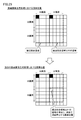
- FIG. 7 is a diagram showing an example of a distance image generated from the pair of input images shown in FIG. 6 in accordance with the image processing method related to the present invention. That is, FIG. 7A shows the entire distance image, and FIG. 7B shows an enlarged view of a part of the area shown in FIG. As shown in FIG. 7, the magnitude of the parallax (distance information) associated with each point of the input image 1 is expressed by the shade of the corresponding point.
- FIG. 7 shows an example in which the corresponding point search is executed for each unit region of 32 pixels ⁇ 32 pixels. That is, in the example shown in FIG. 7, the corresponding points are searched for each unit region defined by an interval of 32 pixels on both the X axis (horizontal direction) and the Y axis (vertical direction). The distance between is calculated. A distance image indicating the distance between the searched corresponding points is generated so as to match the pixel size of the input image.
- the distance is calculated at search points of 108 points ⁇ 81 points, and the pixel size of the input image is calculated from the calculated distances. A corresponding distance image is generated.
- step S2 in FIG. 5 smoothing processing
- This smoothing process is executed by the smoothing processing unit 36 shown in FIG. In this smoothing process, the entire distance image is averaged.
- FIG. 8 is a diagram showing an example of the averaging filter used in the smoothing process (step S2) of FIG.
- an averaging filter of 189 pixels ⁇ 189 pixels as shown in FIG. 8 is applied.
- the average value of the pixel values (parallax) of the distance image included in the range of the vertical direction 189 pixels and the horizontal direction 189 pixels centering on the target pixel is calculated as a new pixel value of the target pixel. More specifically, a new pixel value of the target pixel is calculated by dividing the sum of the pixel values of the pixels included in the filter by the pixel size of the filter.
- an average value of pixels extracted by thinning out at predetermined intervals may be used. Even when such a thinning process is performed, a smoothing result similar to the case where the average value of all pixels is used may be obtained. In such a case, the processing is performed by performing the thinning process. The amount can be reduced.
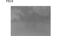
- FIG. 9 is a diagram showing a result of performing the smoothing process on the distance image shown in FIG. In the distance image after the smoothing process shown in FIG. 9, it can be seen that the pixel value (parallax) does not change greatly between adjacent pixels.
- the pixel size of the distance image obtained by the smoothing process is preferably the same pixel size as the input image. By making the pixel size the same, the distance of each pixel can be determined on a one-to-one basis in a stereo image generation process to be described later.
- a stereo image generation process (step S3 in FIG. 5) is executed using the acquired distance image.
- This stereo image generation process is executed by the 3D image generation unit 38 shown in FIG.
- the right-eye image is generated by shifting each pixel of the input image 1 (left-eye image) by a corresponding distance.
- FIG. 10 is a diagram for explaining a processing procedure in the stereo image generation processing (step S3) of FIG.
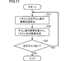
- FIG. 11 is a flowchart showing a processing procedure of the stereo image generation processing shown in FIG.
- a stereo image (right eye image and left eye image) is generated from input image 1 based on the distance image.
- the input image 1 is used as it is as an image for the left eye, and the position of each pixel of the input image 1 is shifted according to the corresponding distance (parallax).
- An ophthalmic image is generated.
- the right-eye image is generated by shifting the pixel position in units of lines constituting the input image 1 (left-eye image).
- FIG. 10 shows, as an example, ten pixels whose pixel positions (coordinates) are “101”, “102”,..., “110” in a line of the input image.
- the distance (parallax) corresponding to the pixel at each pixel position is “40”, “40”, “41”, “41”, “41”, “42”, “42”, “41”, “40”, It is assumed that “40”.
- an image corresponding to one line of the right-eye image is generated.
- the pixel values of the deficient pixels are interpolated using information from adjacent pixels.
- the direction in which the pixel position is shifted is a direction in which parallax should be generated, and specifically corresponds to a direction that becomes the horizontal direction when displayed toward the user.
- step S31 the 3D image generation unit 38 calculates the pixel position after each shift for the pixels of one line of the input image 1 (step S31). Subsequently, the 3D image generation unit 38 generates an image for one line (right eye image) from the shifted pixel position calculated in step S1 (step S32).
- the 3D image generation unit 38 determines whether or not there is an unprocessed line in the input image (step S33). If there is an unprocessed line in the input image (NO in step S33), the next line is selected, and the processes in steps S31 and S32 are repeated.
- the 3D image generation unit 38 outputs the generated right-eye image together with the input image 1 (left-eye image). Then, the process ends.
- FIG. 12 is a diagram showing an example of a stereo image generated by the image processing method related to the present invention. 12A shows a left eye image, and FIG. 12B shows a right eye image.
- FIG. 12B shows that the image for the right eye shown in FIG. 12B is distorted with respect to the “signboard” in the left region.
- the subject there is a “shrub group” on the front side of the “signboard” (side closer to the image pickup unit 2), and the “tachiki group” on the rear side of the “signboard” (side far from the image pickup unit 2). For this reason, it is considered that the distance (parallax) associated with the pixels around the “signboard” varies relatively greatly in the distance image.
- the “signboard”, which is an artifact, has an idea that it has a linear structure, and the “signboard” is bent and displayed, giving the user a sense of incongruity.
- a subject in an area where the distance from the imaging means varies greatly (hereinafter also referred to as “perspective competition area”) is likely to be distorted, and an artificial object having a straight line or the like exists in this distance competition area. The distortion is particularly noticeable.
- the image processing method according to the present embodiment provides a method for suppressing the occurrence of such distortion.
- the sensitivity of the distance information calculated for each of the vertical direction and the horizontal direction of the input image is made different in the process of generating the distance image for the subject.
- the pixel size of a unit area which is a processing unit in the corresponding point search process and the distance image generation process is made different between the vertical direction and the horizontal direction.
- the vertical pixel interval defining the unit region is set shorter than the horizontal pixel interval.
- a unit region of 32 pixels ⁇ 32 pixels both vertical and horizontal directions is 32 pixel intervals
- coarser pixel spacing is employed.
- the corresponding point search process and the distance image generation process are executed in a unit region of 64 pixels in the vertical direction ⁇ 32 pixels in the horizontal direction.
- the distance image is generated after the image information is compressed. Accordingly, the calculation sensitivity of the distance between the pixels arranged in the direction in which the parallax is generated is reduced while the calculation accuracy is maintained, and the calculation sensitivity is reduced for the distance between the pixels arranged in the direction in which the parallax does not occur.
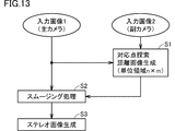
- FIG. 13 is a schematic block diagram showing the procedure of the image processing method according to the first embodiment of the present invention.
- the schematic block diagram shown in FIG. 13 differs from the schematic block diagram shown in FIG. 5 in the corresponding point search process and the distance image generation process (step S1).
- the other processes are the same as those described with reference to FIG. 5, and thus detailed description will not be repeated.
- the pixel size of the unit area used for the process is different between the vertical direction and the horizontal direction.
- the horizontal direction is set in units of 32 pixels in the same manner as the process shown in FIG. 5, while the vertical direction is set for each unit region defined in coarser units of 64 pixels.
- the parallax is generated in the vertical direction, the relationship between the pixel increments in the horizontal direction and the vertical direction is reversed.
- each distance is calculated in units obtained by dividing the input image by 32 pixels in the horizontal direction and 64 pixels in the vertical direction.
- FIG. 14 is a diagram showing an example of a distance image generated from the pair of input images shown in FIG. 6 according to the image processing method according to the first embodiment of the present invention. That is, FIG. 14A shows the entire distance image, and FIG. 14B shows an enlarged view of a part of the area shown in FIG.
- one pixel of the distance image corresponds to a region of 32 pixels in the horizontal direction ⁇ 64 pixels in the vertical direction of the input image 1.
- step S2 The smoothing process (step S2) shown in FIG. 5 is applied to the distance image acquired in this way.
- an averaging filter of 189 pixels ⁇ 189 pixels as shown in FIG. 8 is applied.
- FIG. 15 is a diagram showing a result of smoothing processing performed on the distance image shown in FIG. It can be seen that the distance image after the smoothing process shown in FIG. 15 is more or less identical in the vertical direction compared to the result of the smoothing process shown in FIG. That is, the vertical change in the distance image shown in FIG. 15 is slower than the vertical change in the distance image shown in FIG. Thereby, the distances in the vertical direction of the distance image shown in FIG.
- FIG. 16 is a diagram showing an example of a stereo image generated by the image processing method according to the first embodiment of the present invention.
- FIG. 16A shows a left-eye image
- FIG. 16B shows a right-eye image.
- the “signboard” is generated due to the effect that the distances are roughly aligned in the vertical direction of the distance image after the smoothing process as described above. It can be seen that the distortion which has been suppressed is suppressed. That is, according to the present embodiment, it is possible to acquire a stereo image in which image distortion is not noticeable.
- the pixel size as described above is made different between the vertical direction and the horizontal direction for an area including an “artifact” in the subject.
- Corresponding point search processing and distance image generation processing are executed for each unit region. That is, for a region where an “artifact” is present, a distance image is generated in a unit region having a different pixel size in the vertical direction and the horizontal direction. For a region where no “artifact” is present, a distance image is generated in a normal unit region. Is generated.
- the distance (parallax) is calculated so that distortion is less likely to occur in the “artifact” that is prominently distorted and the surrounding image, and the accuracy of calculating the distance (parallax) is increased in other areas.
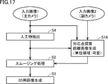
- FIG. 17 is a schematic block diagram showing the procedure of the image processing method according to the second embodiment of the present invention.
- the schematic block diagram shown in FIG. 17 differs from the schematic block diagram shown in FIG. 13 in the content of the corresponding point search process and the distance image generation process (step S1A), and the artifact extraction process (step S4) is added.
- Other processes are the same as the corresponding processes in FIG. 13, and thus detailed description will not be repeated.
- step S1A of FIG. 17 the area (artificial area) where the artifact extracted in the artifact extraction process (step S4) exists (and in the vicinity thereof).
- the pixel size of the unit area used for processing is made different between the vertical direction and the horizontal direction.
- the distance is calculated in a unit divided by 32 pixels in the horizontal direction ⁇ 64 pixels in the vertical direction, and for the other regions, 32 pixels in the horizontal direction.
- X Distance is calculated in units divided by 32 pixels in the vertical direction. Note that when the parallax is generated in the vertical direction, the relationship between the pixel increments in the horizontal direction and the vertical direction is reversed.
- step S4 shown in FIG. 17 is executed prior to the corresponding point search process and the distance image generation process (step S1A).
- step S4 an area where “artifact” exists is extracted as a feature area. Whether this is an “artifact” is determined by extracting a characteristic shape in the input image. More specifically, the “artificial object” is extracted based on one or more feature amounts of a straight line, a quadratic curve, a circle, an ellipse, and a texture (pattern repeat pattern). Various methods can be adopted as a method of extracting an “artificial object” based on such a feature amount.
- FIG. 18 is a flowchart showing the processing procedure of the artifact extraction process shown in FIG. Each step shown in FIG. 18 is executed by the area determination unit 34 shown in FIG.
- the region determination unit 34 detects a contour (edge) included in the input image 1 (step S41).
- a contour edge included in the input image 1
- various methods can be employed.
- the region determination unit 34 performs edge processing in the input image 1 by performing image processing using the Canny algorithm or the like. To extract. Since the Canny algorithm is known, it will not be described in detail.
- image processing using a differential filter such as a Sobel filter may be employed.
- the area determination unit 34 detects a basic figure constituting each of the edges (step S42).
- the “basic figure” is obtained by giving a specific numerical value as a parameter to a predetermined function such as a straight line, a quadratic curve, a circle (or arc), and an ellipse (or elliptic arc).
- a predetermined function such as a straight line, a quadratic curve, a circle (or arc), and an ellipse (or elliptic arc).
- a figure whose shape and / or size can be specified in a coordinate space.
- the area determination unit 34 specifies a basic figure by performing a Hough transform on each detected edge.
- the area determination unit 34 determines that the detected basic figure (straight line or arc) is longer than a predetermined value as an “artificial object”. That is, the area determination unit 34 measures the length (number of connected pixels) of each detected basic figure, and the measured length is a predetermined threshold value (for example, 300 pixels) or more. A thing is specified as a basic figure (step S43). And the area
- the area determination unit 34 specifies an artifact area based on the bold basic figure (step S44). More specifically, the area determination unit 34 calculates the ratio of the length of the basic figure constituting the edge to the length of the edge, and the ratio of the calculated lengths of the detected edges is a predetermined condition. Edges that satisfy (for example, 75% or more) are extracted. Then, the region determination unit 34 identifies the inside of the edge that satisfies the predetermined condition as an artifact region. Further, a quadratic curve, an ellipse, or the like may be extracted by appropriately setting the predetermined condition.
- the area determination unit 34 determines the ratio of the length of one or more types of predetermined basic figures constituting the edge to the length of the edge in the input image 1 as a determination condition (input image Is adopted as a geometric condition).
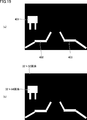
- FIG. 19 shows an example of a result of performing the artifact extraction process of the image processing method according to the second embodiment of the present invention.
- a “white” area indicates an area determined as an artifact area
- a “black” area indicates an area that is not determined as an artifact area.
- the processing result shown in FIG. 19 corresponds to the input image 1 in FIG. 6A, and the artifact regions 401, 402, and 403 are extracted.
- the artifact region 401 is a region corresponding to the “signboard” located on the left side of the input image 1, and the artifact regions 402 and 403 are regions corresponding to the outer edge of the sidewalk of the input image 1.
- a distance is calculated in a unit region of 32 pixels ⁇ 64 pixels, and for other regions (“black” region) The distance is calculated in a unit region of 32 pixels ⁇ 32 pixels.
- feature point information such as a refraction point is extracted from point sequence information constituting a line included in an input image, and based on these feature point information, a triangle composed of at least three basic figures, Detect closed figures such as rectangles. Furthermore, a rectangular area that contains the detected closed figure at a rate equal to or greater than a predetermined reference value may be specified, and the specified rectangular area may be extracted as an artifact area.
- an artifact region extraction process methods disclosed in Japanese Patent Application Laid-Open Nos. 2000-353242 and 2004-151815 may be employed.
- the artifact region may be extracted based on “complexity” included in the input image.
- the degree of “complexity” in an image is lower in an artifact area than in an area corresponding to a natural object that is not an artifact. Therefore, an index value indicating “complexity” of the image may be calculated, and the artifact region may be extracted based on the calculated index value. That is, the complexity of the image in the input image 1 is adopted as a determination condition (geometric condition for the input image) for determining the artifact region.
- a fractal dimension that is a scale expressing the autocorrelation of a figure may be adopted. In general, the value of the fractal dimension increases as the image becomes more complex. Therefore, the “complexity” of the image can be evaluated based on the size of the fractal dimension.
- a natural object region may be extracted from the fractal dimension disclosed in Japanese Patent Application Laid-Open No. 06-343140, and an area other than the extracted natural object region may be extracted as an artifact region.
- step S1A Corresponding point search process and distance image generation process
- a unit region for example, the transverse direction 32 is set with a different pixel size in the vertical direction and the horizontal direction.
- Pixel ⁇ vertical 64 pixels is set, and for other regions, a normal unit region (as an example, horizontal 32 pixels ⁇ vertical 32 pixels) is set.
- corresponding point search processing and distance image generation processing are executed according to the set unit region.
- the distance is calculated in a unit region of 32 pixels in the horizontal direction ⁇ 64 pixels in the vertical direction.
- a distance distance image is calculated using a unit region of 32 pixels in the horizontal direction ⁇ 32 pixels in the vertical direction.
- a distance image substantially identical in the vertical direction is generated only for a region where distortion generated in the generated stereo image is expected to be conspicuous, and for other regions Since it is possible to maintain the generation accuracy of the distance image, it is possible to realize a stereoscopic display with a sharp feeling while suppressing image distortion.
- the pixel size as described above is set for the “distance competing region”, which is a region where the variation in distance is relatively large among subjects.
- Corresponding point search processing and distance image generation processing are executed for each unit region that is different in the vertical direction and the horizontal direction.
- a distance image is generated in a unit area having different pixel sizes in the vertical direction and the horizontal direction, and for an area that is not a “distance competing area”, a distance image is generated in a normal unit area. To do.
- the distance (parallax) is calculated so that the “distant competitive region” in which distortion is conspicuous is less likely to cause distortion, and the accuracy of calculating the distance (parallax) is increased for other regions.
- FIG. 20 is a schematic block diagram showing the procedure of the image processing method according to the third embodiment of the present invention.
- the schematic block diagram shown in FIG. 20 has a perspective conflict extraction process (step S5) and an additional distance image generation process (step S1B) added to the schematic block diagram shown in FIG.
- Other processes are the same as the corresponding processes in FIG. 13, and thus detailed description will not be repeated.
- the distance is acquired for each rough unit area in the vertical direction only for the near and far conflict areas, and the distance is acquired for each normal unit area for the other areas.
- step S1 of FIG. 20 first, unit regions having different pixel sizes in the vertical direction and the horizontal direction (for example, 32 pixels in the horizontal direction ⁇ vertical direction). The distance is acquired in the direction (64 pixels).
- step S5 a perspective conflict region is extracted, and for regions other than the extracted perspective conflict region, a unit region (for example, the vertical direction and the horizontal direction have the same pixel size)
- step S1B the distance is acquired by 32 pixels in the horizontal direction ⁇ 32 pixels in the vertical direction (step S1B).
- step S1B since the distance is acquired first in step S1, only the distance of the missing part is additionally acquired in step S1B.
- the perspective area is extracted first, and for the area extracted as the perspective area, a unit area in which the pixel size is different in the vertical direction and the horizontal direction is used.
- the necessary distance may be calculated by setting a normal unit area for the areas other than the perspective conflict areas.
- step S5 the near and far conflict area extraction process
- the perspective conflict region extraction process it is determined whether or not the pixel is a perspective conflict region based on the distribution state of the distance from the imaging unit 2 for each pixel in the attention region. That is, when the distribution with respect to the distance from the imaging unit 2 is relatively wide and discrete, it is determined that the region is a near and far conflict region.
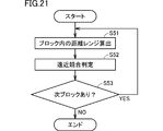
- FIG. 21 is a flowchart showing a processing procedure of the near and far conflict area extraction process shown in FIG. Each step shown in FIG. 21 is executed by the area determination unit 34 shown in FIG.
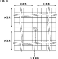
- FIG. 22 is a diagram showing an example of blocks set in the processing procedure of the near and far conflict area extraction process shown in FIG.
- FIG. 23 is a diagram illustrating an example of a histogram regarding the distance between pixels included in the block 411 illustrated in FIG. 22.
- the area determination unit 34 sets one or more blocks for the distance image acquired by executing the corresponding point search process and the distance image generation process (step S1). .
- the block 411 to be set is typically a rectangular area, and has a predetermined pixel size (for example, 320 pixels ⁇ 320 pixels). It should be noted that the number of pixels included in this block is preferably a number that allows effective statistical processing.
- the area determination unit 34 selects one of the set blocks, and statistically processes each distance information included in the selected block. Then, the region determination unit 34 acquires a statistical distribution state regarding the distance information in the selected block. More specifically, a histogram as shown in FIG. 23 is calculated.
- This histogram is an example of a statistical distribution state for the distance information in the block 411 set in FIG.
- the horizontal axis indicates a distance (parallax) section divided by a predetermined width
- the vertical axis indicates the frequency (number) of pixels belonging to the distance (parallax) corresponding to each section. .
- a block 411 illustrated in FIG. 22 corresponds to the area where the “signboard” of the input image 1 illustrated in FIG. 5 exists, and the “shrub group” that is located closer to the imaging unit 2 than the “signboard”. “Tachiki group” present at a position farther from the imaging unit 2 than the “signboard” is included as a subject.
- the distribution of the distance information of the pixels included in the block 411 is expressed as a histogram with parallax (distance information) as a variable, the peak of the frequency distribution appears discretely (discontinuously) as shown in FIG. In addition, the distribution width of the parallax becomes relatively wide.
- the block 411 in FIG. when the frequency distribution peak appears discretely (discontinuously) and the parallax distribution width becomes relatively wide, the block 411 in FIG.
- the variation in the distance from the imaging unit 2 is relatively large. Therefore, it can be said that a foreground subject that is relatively close to the imaging unit 2 and a far-field subject that is relatively far from the imaging unit 2 are mixed. In such a state, it can be determined that the target block 411 is set as the “far / near conflict area”.
- the “distance range” of the histogram is adopted as an index value for determining such a “far-and-coming competitive area”.
- the “distance range” means a width indicating the spread of the histogram. More specifically, the “distance range” is the disparity (distance information) corresponding to the pixels corresponding to the top 5% when counting all pixels included in the block 411 in descending order of the parallax value. It means the difference (distribution width) from the parallax (distance information) corresponding to the pixels corresponding to the lower 5% when counted in order from the smallest parallax value.
- the reason why the range from the upper 5% to the lower 5% is the distance range is that the acquired disparity (distance information) is significantly different from the original value due to an error in the corresponding point search by the corresponding point search processing. This is to remove the pixel (noise component).
- the region determination unit 34 calculates the distance range in the selected block (step S51 in FIG. 21). Subsequently, the region determination unit 34 determines whether or not the currently set block 411 is a perspective conflict region based on the distance range calculated in step S51 (step S52). That is, the region determination unit 34 determines whether or not the statistical distribution state of the distance information in the selected block 411 satisfies a predetermined condition that defines the near and far conflict region. More specifically, the region determination unit 34 determines whether or not the distance range calculated in step S51 exceeds a predetermined threshold (for example, “20”).
- a predetermined threshold for example, “20”.
- the region determination unit 34 stores the determination result of whether or not the currently set block 411 is a perspective conflict region, and determines whether or not there is a region for which no block is set for the distance image. (Step S53). If there is an area where no block is set (NO in step S53), the next block is set, and the processes in steps S51 and S52 are repeated.
- the region determination unit 34 determines whether the region is a perspective conflict region in association with the coordinates on the image coordinate system of the distance image. The identification information of is output. Then, the process ends.
- distance range is adopted as an index value indicating a statistical distribution state, but another index may be employed.
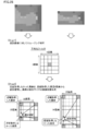
- FIG. 24 is a diagram showing an example of a result of performing a near and far conflict area extraction process of the image processing method according to the third embodiment of the present invention.
- a “white” region indicates a region determined as a perspective conflict region
- a “black” region indicates a region that is not determined as a perspective conflict region.
- the processing result shown in (a) of FIG. 24 corresponds to the input image 1 of (a) of FIG. 6, and the area where the “signboard” and the “standing tree group” exist is extracted as the perspective conflict area. .
- a distance is calculated in a unit region of 32 pixels ⁇ 64 pixels, and for other regions (“white” region) The distance is calculated in a unit region of 32 pixels ⁇ 32 pixels.
- step S1B Corresponding point search process and distance image generation process
- FIG. 25 is a diagram for explaining processing contents in the corresponding point search processing, distance image generation processing (step S1), and additional distance image generation processing (step S1B) shown in FIG.
- step S1 distances are calculated in a unit area of 32 pixels ⁇ 64 pixels for all of the near and far conflict areas and the other areas. Since the corresponding point search process and the distance image generation process (step S1) are executed prior to the perspective conflict area extraction process (step S5), the perspective conflict area is not specified at this time.
- an additional distance calculating process is executed for the area other than the distance competing area in the additional distance image generation process (step S1B).
- the unit area whose distance is calculated with respect to the near and far conflict area has a pixel size of 32 pixels ⁇ 64 pixels, and is twice the pixel size of the normal unit area. Therefore, for regions other than the near and far conflict regions, one additional distance is calculated for each unit region (32 pixels ⁇ 64 pixels) for which the distance has been previously calculated.
- the distance is calculated in a unit region of 32 pixels ⁇ 32 pixels. Additional distance calculation processing is executed.
- a distance image substantially identical in the vertical direction is generated only for a region where distortion generated in the generated stereo image is expected to be conspicuous, and for other regions Since it is possible to maintain the generation accuracy of the distance image, it is possible to realize a stereoscopic display with a sharp feeling while suppressing image distortion.
- Embodiment 4 In the second embodiment, an “artifact region” is extracted, and a distance is calculated for the extracted “artifact region” in unit regions having different pixel sizes in the vertical direction and the horizontal direction. Shows an example in which a “distance competing region” is extracted, and a distance is calculated for the extracted “distance competing region” in unit regions having different pixel sizes in the vertical and horizontal directions.
- a method may be considered in which the distance is calculated using unit regions having different pixel sizes in the vertical direction and the horizontal direction only for the “artifact region” and the “perspective competition region”. It is done.
- the “AND” condition of such an area it is possible to generate a stereo image while leaving the stereoscopic effect as much as possible.
- a distance is calculated in a unit divided by 32 pixels in the horizontal direction ⁇ 64 pixels in the vertical direction, and the “artifact region” and “ For the region determined to be only one of the “far and near conflict regions”, the distance is calculated in units divided by 32 pixels in the horizontal direction ⁇ 48 pixels in the vertical direction, and the “artificial region” and the “far and far conflict region” For regions determined to be neither, the distance may be calculated in units divided by 32 pixels in the horizontal direction and 32 pixels in the vertical direction.
- the distance may be calculated with finer accuracy according to the attribute of the region. Therefore, it is possible to more surely realize a stereoscopic display with a sharp feeling while suppressing image distortion.
- the smoothing process (step S2) can be modified as follows. That is, smoothing processing according to the directionality of the pixel size of the unit area may be performed on the distance image.
- FIG. 26 is a schematic block diagram showing the procedure of the image processing method according to the first modification of the embodiment of the present invention.
- FIG. 27 is a diagram illustrating an example of an averaging filter used in the smoothing process (step S2) illustrated in FIG.
- FIG. 26 shows an example in which the filtering process in the image processing method according to the first embodiment shown in FIG. 13 is modified as a typical example, but the present invention can be similarly applied to other embodiments.
- an averaging filter having different pixel sizes in the vertical direction and the horizontal direction as shown in FIG. 27 may be used.
- the averaging filter shown in FIG. 27 is set to a pixel size associated with a unit area related to distance image generation.
- the smoothing process in the present embodiment may be realized by a two-stage process.
- FIG. 28 is a diagram for explaining the smoothing process according to the second modification of the embodiment of the present invention.
- the first step (Step 1), smoothed distance information is generated by applying an averaging filter to the distance image (an image made up of only the pixels from which the distance has been acquired).
- the distance image (original distance image) to be subjected to the averaging filter in the first stage has an input image size of 3456 pixels ⁇ 2592 pixels, and a size of a unit area where a corresponding point search is performed is 32 pixels ⁇ 32 pixels. When it is a pixel, it has a pixel size of 108 pixels ⁇ 81 pixels.
- Step 2 in order to generate a distance image having a pixel size corresponding to the input image 1, the pixel values of the peripheral pixels and the distance to the pixels are determined for the pixels for which distance acquisition has not been performed. Each pixel value is calculated by performing linear interpolation accordingly.
- Step 1 an averaging filter having a fixed pixel size (for example, 5 pixels ⁇ 5 pixels) is used regardless of the pixel size of the unit area for which the distance is calculated.
- Step 2 a distance image corresponding to the pixel size of the input image is generated by performing linear interpolation with a size corresponding to the pixel size of the unit region for calculating the distance.
- Step 1 shown in FIG. 28 by changing the size of the averaging filter, the image distortion similar to the image processing method according to the present embodiment can be suppressed by applying a stronger smoothing process in the vertical direction or the horizontal direction. . More specifically, in Step 1 shown in FIG. 28, a distance image in which image distortion in the vertical direction is suppressed can be obtained by using an averaging filter of 5 pixels ⁇ 9 pixels, as in the image processing method according to the present embodiment. Can be generated. However, according to this method, since a larger averaging filter is used as compared with the image processing method according to the present embodiment, a larger amount of processing is required.
- the distance image (Step 1) that is generated first is obtained by making the image size of the unit region for calculating the distance (parallax) different in the vertical direction and the horizontal direction. Since the pixel size of the averaging filter can be reduced, the pixel size of the averaging filter can be further reduced, thereby obtaining the effect of speeding up the processing and reducing the hardware scale.
- DESCRIPTION OF SYMBOLS 1 Image processing system 2 Imaging part, 3 Image processing part, 4 Image output part, 21 1st camera, 21a, 22a lens, 21b, 22b Image sensor, 22 2nd camera, 23, 24 A / D conversion part, 30
- Corresponding point search unit 32 distance image generation unit, 34 area determination unit, 36 smoothing processing unit, 38 image generation unit, 100 digital camera, 102 CPU, 104 digital processing circuit, 106 image processing circuit, 108 image display unit, 112 storage Part, 114 zoom mechanism, 121 primary camera, 122 secondary camera, 200 personal computer, 202 personal computer body, 204 image processing program, 206 monitor, 208 mouse, 210 keyboard, 212 external storage device.
Abstract
画像処理システム(1)は、被写体を撮像して第1の入力画像を取得する第1の撮像手段(21,23)と、第1の撮像手段とは異なる視点から被写体を撮像して第2の入力画像を取得する第2の撮像手段(22,24)と、第1の入力画像と第2の入力画像との間における被写体の各点についての対応関係に基づいて、所定の画素サイズを有する単位領域毎に、所定位置を基準とした距離を示す距離情報を取得する距離情報取得手段(3)とを含む。単位領域は、第1の入力画像における第1の方向に対応する第1の画素間隔と、第2の方向に対応する第1の画素間隔とは異なる第2の画素間隔とによって定められる。
Description
本発明は、被写体を立体視表示するための画像生成に向けられた画像処理システム、画像処理方法および画像処理プログラムに関する。
近年の表示デバイスの開発とも相まって、同一対象物(被写体)を立体視表示するための画像処理技術の開発が進められている。このような立体視表示を実現する典型的な方法として、人間が感じる両眼視差を利用する方法がある。このような両眼視差を利用する場合には、撮像手段から被写体までの距離に応じて視差をつけた一対の画像(以下「ステレオ画像」または「3D画像」とも称す。)を生成する必要がある。
例えば、特開2008-216127号公報(特許文献1)に開示される技術では、複数の撮像手段により被写体を異なる位置から撮像することで複数の画像情報を取得し、SAD(Sum of Absolute Difference)演算法、SSD(Sum of Squared Difference)演算法などによる相関演算を行なうことによりこれらの画像情報の相関度を算出する。そして、算出された相関度に基づいて被写体に対する視差値を算出し、視差値から被写体の位置(距離値)を算出することで距離画像を生成する。さらに、特開2008-216127号公報(特許文献1)には、処理時間の短縮を図りつつ、サブピクセルレベルの演算において高精度の演算結果を得て信頼性の高い距離画像を生成するための構成が開示されている。
上述のような方法でステレオ画像を生成した場合には、画像に歪みが生じる場合がある。このような歪みによって、例えば、直線的な構造を有する人工物が被写体に含まれているような場合には、その人工物の形状をユーザーが予め知っているので、生じた歪みが目立つという課題がある。このような歪みは、被写体に対する視差値を算出する際の2つの画像間での対応点を正しく探索できない場合や、撮像手段からの距離が大きくばらつく領域が被写体に含まれている場合などに生じ得る。
このような画像の歪みを回避するために、視差を示す距離画像を画像に歪みが生じない程度まで滑らかにするという方法も考えられるが、このような方法を採用した場合には、画像のメリハリ感が失われてしまうという課題が生じる。
そこで、本発明は、かかる問題を解決するためになされたものであり、その目的は、画像の歪みを抑制しつつ、メリハリ感のある立体視表示に適した画像処理システム、画像処理方法および画像処理プログラムを提供することである。
本発明のある局面に従う画像処理システムは、被写体を撮像して第1の入力画像を取得する第1の撮像手段と、第1の撮像手段とは異なる視点から被写体を撮像して第2の入力画像を取得する第2の撮像手段と、第1の入力画像と第2の入力画像との間で、所定の画素サイズを有する単位領域毎に、所定位置を基準とした距離を示す距離情報を取得する距離情報取得手段とを含む。単位領域は、第1の入力画像における第1の方向に対応する第1の画素間隔と、第2の方向に対応する第1の画素間隔とは異なる第2の画素間隔とによって定められる。
好ましくは、画像処理システムは、距離情報に基づいて、第1の入力画像に含まれる画素を第1の方向にずらすことで被写体を立体視表示するためのステレオ画像を生成する立体視生成手段をさらに含み、単位領域を定める第1の画素間隔は、第2の画素間隔より短く構成される。
さらに好ましくは、画像処理システムは、距離情報を示す距離画像に対して、単位領域の画素サイズの方向性に応じたスムージング処理を行なうスムージング処理手段をさらに含む。
好ましくは、画像処理システムは、被写体に含まれる特徴領域を判定する領域判定手段をさらに含み、距離情報取得手段は、抽出された特徴領域を含む単位領域について画素サイズを変更する。
さらに好ましくは、特徴領域は、直線、2次曲線、円、楕円、テクスチャのいずれかを含む。
あるいはさらに好ましくは、特徴領域は、距離のばらつきが相対的に大きな領域である遠近競合領域を含む。
好ましくは、距離情報取得手段は、第1の入力画像と第2の入力画像との間における被写体の各点についての対応関係に基づいて、距離情報を取得する。
本発明の別の局面に従う画像処理方法は、被写体を撮像して第1の入力画像を取得するステップと、第1の入力画像を撮像した視点とは異なる視点から被写体を撮像して第2の入力画像を取得するステップと、第1の入力画像と第2の入力画像との間で、所定の画素サイズを有する単位領域毎に、所定位置を基準とした距離を示す距離情報を取得するステップとを含む。単位領域は、第1の入力画像における第1の方向に対応する第1の画素間隔と、第2の方向に対応する第1の画素間隔とは異なる第2の画素間隔とによって定められる。
本発明のさらに別の局面に従う画像処理プログラムは、コンピューターに画像処理を実行させる。画像処理プログラムは、コンピューターに、被写体を撮像した第1の入力画像を取得するステップと、第1の入力画像を撮像した視点とは異なる視点から被写体を撮像した第2の入力画像を取得するステップと、第1の入力画像と第2の入力画像との間で、所定の画素サイズを有する単位領域毎に、所定位置を基準とした距離を示す距離情報を取得するステップとを実行させる。単位領域は、第1の入力画像における第1の方向に対応する第1の画素間隔と、第2の方向に対応する第1の画素間隔とは異なる第2の画素間隔とによって定められる。
本発明によれば、画像の歪みを抑制しつつ、メリハリ感のある立体視表示を行なうことができる。
本発明の実施の形態について、図面を参照しながら詳細に説明する。なお、図中の同一または相当部分については、同一符号を付してその説明は繰り返さない。
<A.概要>
本発明の実施の形態に従う画像処理システムは、被写体を複数の視点でそれぞれ撮像することで得られる複数の入力画像から立体視表示を行なうためのステレオ画像を生成する。このステレオ画像の生成にあたって、2つの入力画像の間で、所定の画素サイズを有する単位領域毎に距離情報を取得する。そして、この取得したそれぞれの点の距離情報からステレオ画像が生成される。
本発明の実施の形態に従う画像処理システムは、被写体を複数の視点でそれぞれ撮像することで得られる複数の入力画像から立体視表示を行なうためのステレオ画像を生成する。このステレオ画像の生成にあたって、2つの入力画像の間で、所定の画素サイズを有する単位領域毎に距離情報を取得する。そして、この取得したそれぞれの点の距離情報からステレオ画像が生成される。
本実施の形態に従う画像処理システムでは、縦方向および横方向で異なる画素サイズを有する単位領域を用いることで、対応関係の探索および距離情報の取得にあたって、所定の方向についての精度を緩める。
これにより、画像の歪みを抑制しつつ、メリハリ感のある立体視表示を実現できる。
<B.システム構成>
まず、本発明の実施の形態に従う画像処理システムの構成について説明する。
<B.システム構成>
まず、本発明の実施の形態に従う画像処理システムの構成について説明する。
(b1:基本的構成)
図1は、本発明の実施の形態に従う画像処理システム1の基本的構成を示すブロック図である。図1を参照して、画像処理システム1は、撮像部2と、画像処理部3と、3D画像出力部4とを含む。図1に示す画像処理システム1においては、撮像部2が被写体を撮像することで一対の入力画像(入力画像1および入力画像2)を取得し、画像処理部3がこの取得された一対の入力画像に対して後述するような画像処理を行なうことで、被写体を立体視表示するためのステレオ画像(右眼用画像および左眼用画像)が生成される。そして、3D画像出力部4は、このステレオ画像(右眼用画像および左眼用画像)を表示デバイスなどへ出力する。
図1は、本発明の実施の形態に従う画像処理システム1の基本的構成を示すブロック図である。図1を参照して、画像処理システム1は、撮像部2と、画像処理部3と、3D画像出力部4とを含む。図1に示す画像処理システム1においては、撮像部2が被写体を撮像することで一対の入力画像(入力画像1および入力画像2)を取得し、画像処理部3がこの取得された一対の入力画像に対して後述するような画像処理を行なうことで、被写体を立体視表示するためのステレオ画像(右眼用画像および左眼用画像)が生成される。そして、3D画像出力部4は、このステレオ画像(右眼用画像および左眼用画像)を表示デバイスなどへ出力する。
撮像部2は、同一対象物(被写体)を異なる視点で撮像して一対の入力画像を生成する。より具体的には、撮像部2は、第1カメラ21と、第2カメラ22と、第1カメラと接続されたA/D(Analog to Digital)変換部23と、第2カメラ22と接続されたA/D変換部24とを含む。A/D変換部23は、第1カメラ21により撮像された被写体を示す入力画像1を出力し、A/D変換部24は、第2カメラ22により撮像された被写体を示す入力画像2を出力する。
すなわち、第1カメラ21およびA/D変換部23は、被写体を撮像して第1の入力画像を取得する第1の撮像手段に相当し、第2カメラ22およびA/D変換部24は、第1の撮像手段とは異なる視点から被写体を撮像して第2の入力画像を取得する第2の撮像手段に相当する。
第1カメラ21は、被写体を撮像するための光学系であるレンズ21aと、レンズ21aにより集光された光を電気信号に変換するデバイスである撮像素子21bとを含む。A/D変換部23は、撮像素子21bから出力される被写体を示す映像信号(アナログ電気信号)をデジタル信号に変換して出力する。同様に、第2カメラ22は、被写体を撮像するための光学系であるレンズ22aと、レンズ22aにより集光された光を電気信号に変換するデバイスである撮像素子22bとを含む。A/D変換部24は、撮像素子22bから出力される被写体を示す映像信号(アナログ電気信号)をデジタル信号に変換して出力する。撮像部2はさらに、各部分を制御するための制御処理回路などを含み得る。
後述するように、本実施の形態に従う画像処理においては、ステレオ画像(右眼用画像および左眼用画像)は、一方のカメラで撮像された入力画像を用いて生成可能である。そのため、後述するような距離画像を生成するための対応点探索処理を実行できれば、第1カメラ21と第2カメラ22との間で機能や性能(典型的には、取得される入力画像の画素サイズなど)を同一にする必要はない。
図2は、図1に示す撮像部2の具体的な構成例を示す図である。図2の(a)に示す撮像部2の一例は、光学ズーム機能付きの主レンズと、光学ズーム機能無しの副レンズとを組み合わせた構成を有している。また、図2の(b)に示す撮像部2の一例は、いずれも光学ズーム機能付きの主レンズを2つ組み合わせた構成を有している。
本実施の形態に従う画像処理方法においては、同一の被写体に対するそれぞれのカメラの視線方向(視点)が異なっていればよいので、撮像部2において、主レンズと副レンズとの配置(縦方向配列または横方向配列)は任意に設定できる。すなわち、図2の(a)または図2の(b)に示す撮像部2を縦長方向に配置して撮像してもよいし、横長方向に配置して撮像してもよい。
後述する撮像例(画像例)については、同一種類のレンズ(光学ズーム機能無し)を縦方向に所定間隔だけ離して2つ配置した構成において取得されたものである。
本実施の形態に従う画像処理方法においては、入力画像1および入力画像2を必ずしも同意に取得する必要はない。すなわち、入力画像1および入力画像2を取得するための撮像タイミングにおいて、被写体に対する撮像部2の位置関係が実質的に同じであれば、入力画像1および入力画像2を異なるタイミングでそれぞれ取得してもよい。また、本実施の形態に従う画像処理方法においては、静止画だけではなく、動画としても立体視表示を行なうためのステレオ画像を生成することができる。この場合には、第1カメラ21および第2カメラ22の間で同期を取りつつ、時間的に連続して被写体を撮像することで、それぞれのカメラについての一連の画像をそれぞれ取得することができる。また、本実施の形態に従う画像処理方法においては、入力画像は、カラー画像であってもよいし、モノクロ画像であってもよい。
再度図1を参照して、画像処理部3は、撮像部2によって取得された一対の入力画像に対して、本実施の形態に従う画像処理方法を実施することで、被写体を立体視表示するためのステレオ画像(右眼用画像および左眼用画像)を生成する。より具体的には、画像処理部3は、対応点探索部30と、距離画像生成部32と、領域判定部34と、スムージング処理部36と、3D画像生成部38とを含む。
対応点探索部30は、一対の入力画像(入力画像1および入力画像2)に対して対応点探索の処理を行なう。この対応点探索の処理は、典型的には、POC(Phase-Only Correlation)演算法、SAD(Sum of Absolute Difference)演算法、SSD(Sum of Squared Difference)演算法、NCC(Normalized Cross Correlation)演算法などを用いることができる。すなわち、対応点探索部30は、入力画像1と入力画像2との間における被写体の各点についての対応関係を探索する。
距離画像生成部32は、2つの入力画像についての距離情報を取得する。この距離情報は、同一の被写体についての情報の相違に基づいて算出される。典型的には、距離画像生成部32は、対応点探索部30によって探索された被写体の各点についての入力画像の間での対応関係から距離情報を算出する。撮像部2は、異なる視点からそれぞれ被写体を撮像する。そのため、2つの入力画像の間では、被写体のある点(注目点)を表現する画素同士は、撮像部2と当該被写体の点との距離に応じた距離だけずれることになる。本明細書においては、入力画像1の注目点に対応する画素の画像座標系上の座標と、入力画像2の注目点に対応する画素の画像座標系上の座標との差を「視差」と称する。距離画像生成部32は、対応点探索部30によって探索された被写体の注目点の各々について、視差を算出する。
この視差は、撮像部2から被写体の対応する注目点までの距離を示す指標値である。視差が大きいほど、撮像部2から被写体の対応する注目点までの距離が短い、すなわち撮像部2により近接していることを意味する。本明細書においては、視差、および、視差によって示される被写体の各点の撮像部2からの距離を、総称して「距離情報」という用語を用いる。
なお、入力画像間で視差が生じる方向は、撮像部2における第1カメラ21と第2カメラ22との間の位置関係に依存する。例えば、第1カメラ21と第2カメラ22とを縦方向に所定間隔だけ離して配置した場合には、入力画像1と入力画像2との間での視差は縦方向に生じることになる。
距離画像生成部32は、被写体の各点についての距離情報として算出し、算出したそれぞれの距離情報を画像座標系上の座標に関連付けて表現した距離画像(視差画像)を生成する。この距離画像の一例については、後述する。
なお、対応点探索部30では、所定の画素サイズを有する単位領域毎に対応点探索が行なわれるため、原始的には、距離画像は、1つの単位領域を1画素とする画像として生成される。
このように、距離画像生成部32は、対応点探索部30によって算出された被写体の各点についての対応関係に基づいて、所定の画素サイズを有する単位領域毎に、撮像部2が配置された位置を基準とした距離を示す距離情報を取得する。さらに、距離画像生成部32は、取得した距離情報を表現した距離画像を生成する。
本実施の形態に従う画像処理方法においては、対応点探索部30による対応点探索処理および距離画像生成部32による距離画像生成処理における処理単位である、単位領域の画素サイズを縦方向および横方向との間で異ならせることで、被写体が立体視表示された際に生じる画像の歪みを緩和する。すなわち、単位領域は、入力画像の縦方向に対応する画素間隔と、縦方向に対応する画素間隔とは異なる横方向に対応する画素間隔とによって定められる。
領域判定部34は、入力画像の被写体に含まれる特徴領域を判定する。この特徴領域は、生成されたステレオ画像に生じる歪みが目立つことが予想される領域である。具体的には、直線などの人工物が存在する領域(以下「人工物領域」とも称す。)や、遠近競合領域(距離のばらつきが相対的に大きい領域)などが含まれる。この領域判定部34によって判定された特徴領域の情報に基づいて、対応点探索部30および距離画像生成部32は、対応点探索や距離画像生成に用いる単位領域の画素サイズを変更する。すなわち、対応点探索部30および距離画像生成部32は、抽出された特徴領域を含む単位領域について画素サイズを変更する。
スムージング処理部36は、距離画像生成部32によって生成された距離画像に対してスムージング処理することで、距離画像を入力画像に対応する画素サイズに変換する。すなわち、距離画像は、原始的には単位領域を1画素とする画像として生成されるので、スムージング処理部36は、この距離画像から、入力画像を構成する各画素についての距離情報を算出するために、画素サイズを変換する。本実施の形態においては、縦方向および横方向で異なる画素サイズを有する単位領域を用いるので、スムージング処理部36は、距離画像に対して、この単位領域の画素サイズの方向性に応じたスムージング処理を行なってもよい。
3D画像生成部38は、スムージング処理部36によって得られた距離画像に基づいて、入力画像を構成する各画素を対応する距離情報(画素数)だけずらすことで、被写体を立体視表示するためのステレオ画像(右眼用画像および左眼用画像)を生成する。例えば、3D画像生成部38は、入力画像1を左眼用画像として用いるとともに、入力画像1をその各画素について対応する距離情報(画素数)だけ横方向にずらした画像を右眼用画像として用いる。すなわち、右眼用画像と左眼用画像との間について見れば、被写体の各点は、距離画像によって示される距離情報(画素数)に応じた距離だけ離れて、すなわち距離情報(画素数)に応じた視差が与えられて表現される。これにより、被写体を立体視表示することができる。
このように、3D画像生成部38は、距離情報に基づいて、入力画像に含まれる画素を横方向にずらすことで被写体を立体視表示するためのステレオ画像を生成する。このとき、視差が生じる横方向に比較して、縦方向に沿った画像の歪みは目立ちやすいので、縦方向の情報量を少なくした上で、対応点探索処理および距離画像生成処理が実行される。すなわち、対応点探索処理および距離画像生成処理における処理単位である単位領域の縦方向の画素サイズを横方向の画素サイズより大きくする。これにより、一対の入力画像(入力画像1および入力画像2)についての縦方向の情報量が圧縮されることになる。
なお、生成したステレオ画像を回転した上で立体視表示に用いる場合には、視差を縦方向につける必要があるので、この場合には、単位領域の横方向の画素サイズが縦方向の画素サイズより大きくなるように設定される。
これにより、画像の縦方向における歪みの影響を緩和できるとともに、画像処理に係る処理量についても低減できる。すなわち、単位領域を定める縦方向の画素間隔は、横方向の画素間隔より短く構成される。
3D画像出力部4は、画像処理部3によって生成されるステレオ画像(右眼用画像および左眼用画像)を表示デバイスなどへ出力する。
各部の処理動作の詳細については、後述する。
図1に示す画像処理システム1は、各部を独立に構成することもできるが、汎用的には、以下に説明するデジタルカメラやパーソナルコンピューターなどとして具現化される場合が多い。そこで、本実施の形態に従う画像処理システム1の具現化例について説明する。
図1に示す画像処理システム1は、各部を独立に構成することもできるが、汎用的には、以下に説明するデジタルカメラやパーソナルコンピューターなどとして具現化される場合が多い。そこで、本実施の形態に従う画像処理システム1の具現化例について説明する。
(b2:具現化例1)
図3は、図1に示す画像処理システム1を具現化したデジタルカメラ100の構成を示すブロック図である。図3に示すデジタルカメラ100は、2つのカメラ(主カメラ121および副カメラ122)を搭載しており、被写体を立体視表示するためのステレオ画像を撮像することができる。図3において、図1に示す画像処理システム1を構成するそれぞれのブロックに対応するコンポーネントには、図1と同一の参照符号を付している。
図3は、図1に示す画像処理システム1を具現化したデジタルカメラ100の構成を示すブロック図である。図3に示すデジタルカメラ100は、2つのカメラ(主カメラ121および副カメラ122)を搭載しており、被写体を立体視表示するためのステレオ画像を撮像することができる。図3において、図1に示す画像処理システム1を構成するそれぞれのブロックに対応するコンポーネントには、図1と同一の参照符号を付している。
デジタルカメラ100では、主カメラ121で被写体を撮像することで取得される入力画像が記憶および出力され、副カメラ122で当該被写体を撮像することで取得される入力画像については、主として、上述の対応点探索処理および距離画像生成処理に用いられる。そのため、主カメラ121についてのみ光学ズーム機能が搭載されているとする。
図3を参照して、デジタルカメラ100は、CPU(Central Processing Unit)102と、デジタル処理回路104と、画像表示部108と、カードインターフェイス(I/F)110と、記憶部112と、ズーム機構114と、主カメラ121と、副カメラ122とを含む。
CPU102は、予め格納されたプログラムなどを実行することで、デジタルカメラ100の全体を制御する。デジタル処理回路104は、本実施の形態に従う画像処理を含む各種のデジタル処理を実行する。デジタル処理回路104は、典型的には、DSP(Digital Signal Processor)、ASIC(Application Specific Integrated Circuit)、LSI(Large Scale Integration)、FPGA(Field-Programmable Gate Array)などによって構成される。このデジタル処理回路104は、図1に示す画像処理部3が提供する機能を実現するための画像処理回路106を含む。
画像表示部108は、主カメラ121および/または副カメラ122により提供される画像、デジタル処理回路104(画像処理回路106)によって生成される画像、デジタルカメラ100に係る各種設定情報、および、制御用GUI(Graphical User Interface)画面などを表示する。画像表示部108は、画像処理回路106によって生成されるステレオ画像を用いて、被写体を立体視表示できることが好ましい。この場合、画像表示部108は、3次元表示方式に対応した任意の表示デバイス(3次元表示用の液晶表示装置)によって構成される。このような3次元表示方式としては、パララックスバリア方式などを採用することができる。このパララックスバリア方式では、液晶表示面にパララックスバリアを設けることで、ユーザーの右眼で右眼用画像を視認させ、ユーザーの左眼で左眼用画像を視認させることができる。あるいは、シャッタメガネ方式を採用してもよい。このシャッタメガネ方式では、右眼用画像および左眼用画像を交互に高速で切り替えて表示するとともに、この画像の切り替えに同期して開閉するシャッターが搭載された専用メガネをユーザーが装着することで、立体視表示を楽しむことができる。
カードインターフェイス(I/F)110は、画像処理回路106によって生成された画像データを記憶部112へ書き込み、あるいは、記憶部112から画像データなどを読み出すためのインターフェイスである。記憶部112は、画像処理回路106によって生成された画像データや各種情報(デジタルカメラ100の制御パラメータや動作モードなどの設定値)を格納する記憶デバイスである。この記憶部112は、フラッシュメモリ、光学ディスク、磁気ディスクなどからなり、データを不揮発的に記憶する。
ズーム機構114は、ユーザー操作などに応じて、主カメラ121の撮像倍率を変更する機構である。ズーム機構114は、典型的には、サーボモーターなどを含み、主カメラ121を構成するレンズ群を駆動することで、焦点距離を変化させる。
主カメラ121は、被写体を撮像することでステレオ画像を生成するための入力画像を生成する。主カメラ121は、ズーム機構114によって駆動される複数のレンズ群からなる。副カメラ122は、後述するような対応点探索処理や距離画像生成処理に用いられ、主カメラ121によって撮像される同一の被写体を別の視点から撮像する。
このように、図3に示すデジタルカメラ100は、本実施の形態に従う画像処理システム1の全体を単体の装置として実装したものである。すなわち、ユーザーは、デジタルカメラ100を用いて被写体を撮像することで、画像表示部108において当該被写体を立体的に視認することができる。
(b3:具現化例2)
図4は、図1に示す画像処理システム1を具現化したパーソナルコンピューター200の構成を示すブロック図である。図4に示すパーソナルコンピューター200では、一対の入力画像を取得するための撮像部2が搭載されておらず、任意の撮像部2によって取得された一対の入力画像(入力画像1および入力画像2)が外部から入力される構成となっている。このような構成であっても、本発明の実施の形態に従う画像処理システム1に含まれ得る。なお、図4においても、図1に示す画像処理システム1を構成するそれぞれのブロックに対応するコンポーネントには、図1と同一の参照符号を付している。
図4は、図1に示す画像処理システム1を具現化したパーソナルコンピューター200の構成を示すブロック図である。図4に示すパーソナルコンピューター200では、一対の入力画像を取得するための撮像部2が搭載されておらず、任意の撮像部2によって取得された一対の入力画像(入力画像1および入力画像2)が外部から入力される構成となっている。このような構成であっても、本発明の実施の形態に従う画像処理システム1に含まれ得る。なお、図4においても、図1に示す画像処理システム1を構成するそれぞれのブロックに対応するコンポーネントには、図1と同一の参照符号を付している。
図4を参照して、パーソナルコンピューター200は、パーソナルコンピューター本体202と、モニター206と、マウス208と、キーボード210と、外部記憶装置212とを含む。
パーソナルコンピューター本体202は、典型的には、汎用的なアーキテクチャーに従う汎用コンピューターであり、基本的な構成要素として、CPU、RAM(Random Access Memory)、ROM(Read Only Memory)などを含む。パーソナルコンピューター本体202は、図1に示す画像処理部3が提供する機能を実現するための画像処理プログラム204が実行可能になっている。このような画像処理プログラム204は、CD-ROM(Compact Disk-Read Only Memory)などの記憶媒体に格納されて流通し、あるいは、ネットワークを介してサーバー装置から配信される。そして、画像処理プログラム204は、パーソナルコンピューター本体202のハードディスクなどの記憶領域内に格納される。
このような画像処理プログラム204は、パーソナルコンピューター本体202で実行されるオペレーティングシステム(OS)の一部として提供されるプログラムモジュールのうち必要なモジュールを、所定のタイミングおよび順序で呼出して処理を実現するように構成されてもよい。この場合、画像処理プログラム204自体には、OSが提供するモジュールは含まれず、OSと協働して画像処理が実現される。また、画像処理プログラム204は、単体のプログラムではなく、何らかのプログラムの一部に組込まれて提供されてもよい。このような場合にも、画像処理プログラム204自体には、当該何らかのプログラムにおいて共通に利用されるようなモジュールは含まれず、当該何らかのプログラムと協働して画像処理が実現される。このような一部のモジュールを含まない画像処理プログラム204であっても、本実施の形態に従う画像処理システム1の趣旨を逸脱するものではない。
もちろん、画像処理プログラム204によって提供される機能の一部または全部を専用のハードウェアによって実現してもよい。
モニター206は、オペレーティングシステム(OS)が提供するGUI画面、画像処理プログラム204によって生成される画像などを表示する。モニター206は、図3に示す画像表示部108と同様に、画像処理プログラム204によって生成されるステレオ画像を用いて、被写体を立体視表示できることが好ましい。この場合、モニター206としては、画像表示部108において説明したのと同様に、パララックスバリア方式やシャッタメガネ方式などの表示デバイスによって構成される。
マウス208およびキーボード210は、それぞれユーザー操作を受付け、その受付けたユーザー操作の内容をパーソナルコンピューター本体202へ出力する。
外部記憶装置212は、何らかの方法で取得された一対の入力画像(入力画像1および入力画像2)を格納しており、この一対の入力画像をパーソナルコンピューター本体202へ出力する。外部記憶装置212としては、フラッシュメモリ、光学ディスク、磁気ディスクなどのデータを不揮発的に記憶するデバイスが用いられる。
このように、図4に示すパーソナルコンピューター200は、本実施の形態に従う画像処理システム1の一部を単体の装置として実装したものである。このようなパーソナルコンピューター200を用いることで、ユーザーは、任意の撮像部(ステレオカメラ)を用いて異なる視点で被写体を撮像することで取得された一対の入力画像から、当該被写体を立体視表示するためのステレオ画像(右眼用画像および左眼用画像)を生成することができる。さらに、この生成したステレオ画像をモニター206で表示することで、立体視表示を楽しむこともできる。
<C.関連する画像処理方法>
まず、本実施の形態に従う画像処理方法の内容についての理解を容易にするために、本発明に関連する画像処理方法の内容について先に説明する。
まず、本実施の形態に従う画像処理方法の内容についての理解を容易にするために、本発明に関連する画像処理方法の内容について先に説明する。
図5は、本発明に関連する画像処理方法の手順を示す概略ブロック図である。図5を参照して、本発明に関連する画像処理方法は、主カメラ121および副カメラ122が同一の被写体を撮像することでそれぞれ取得する入力画像1および入力画像2に対して、対応点探索処理および距離画像生成処理(ステップS10)、スムージング処理(ステップS2)、ステレオ画像生成処理(ステップS3)の3つの段階の処理が実行される。以下、各ステップについて詳述する。
(c1:入力画像)
図6は、図1に示す撮像部2によって撮像された一対の入力画像の例を示す図である。図6の(a)は、主カメラ121によって撮像された入力画像1を示し、図6の(b)は、副カメラ122によって撮像された入力画像2を示す。本実施の形態においては、典型例として、主カメラ121および副カメラ122を縦方向に配列(主カメラ121が上側であり、副カメラ122が下側である)した場合の例を示す。
図6は、図1に示す撮像部2によって撮像された一対の入力画像の例を示す図である。図6の(a)は、主カメラ121によって撮像された入力画像1を示し、図6の(b)は、副カメラ122によって撮像された入力画像2を示す。本実施の形態においては、典型例として、主カメラ121および副カメラ122を縦方向に配列(主カメラ121が上側であり、副カメラ122が下側である)した場合の例を示す。
なお、図6の(a)に示す入力画像1は、最終的に出力されるステレオ画像の一方の画像(この例では、左眼用画像)として用いられる。
図6には、説明を容易にするために、画像座標系を便宜的に定義している。より具体的には、入力画像の横方向をX軸とし、入力画像の縦方向をY軸とする直交座標系を採用する。このX軸およびY軸の原点は、便宜上、入力画像の左上端であるとする。また、撮像部2(図1)の視線方向をZ軸とする。この直交座標系は、本明細書中の他の図面についての説明においても利用する場合がある。
上述したように、主カメラ121および副カメラ122を縦方向に配列した撮像部2を用いているので、図6の(a)に示す入力画像1と図6の(b)に示す入力画像2との間には、Y軸方向に沿って視差が生じている。
図6に示す一対の入力画像の被写体としては、左側の領域に「看板」を含む。この「看板」は、後述する「人工物」の一例である。この人工物とは、直線などの基本図形の要素を多く含んで構成された物体を意味する。ここで、「基本図形」とは、例えば、直線、2次曲線、円(または、円弧)、および楕円(または、楕円弧)などのように、所定の関数に具体的な数値をパラメータとして与えることによって、座標空間において形状および/またはサイズを特定可能な図形を意味する。
また、「看板」の下側の領域には、当該「看板」よりも撮像部2に近い位置に存在する「低木群」が被写体として撮像されている。また、「看板」の上側の周辺には、当該「看板」よりも撮像部2から遠い位置に存在する「立木群」が被写体として撮像されている。
そのため、入力画像内の「看板」が存在する領域の周囲には、撮像部2から近い順に(Z軸に沿って)、「低木群」、「看板」、「立木群」が位置することになる。
(c2:対応点探索処理および距離画像生成処理)
図6に示すような一対の入力画像(入力画像1および入力画像2)が取得されると、入力画像の間で対応点探索処理(図5のステップS10)が実行される。この対応点探索処理は、図1に示す対応点探索部30によって実行される。この対応点探索処理では、一方の入力画像の注目点にそれぞれ対応する他方の入力画像の画素(座標値)を特定する。このような対応点探索処理は、POC演算法、SAD演算法、SSD演算法、NCC演算法などを用いたマッチング処理が利用される。
図6に示すような一対の入力画像(入力画像1および入力画像2)が取得されると、入力画像の間で対応点探索処理(図5のステップS10)が実行される。この対応点探索処理は、図1に示す対応点探索部30によって実行される。この対応点探索処理では、一方の入力画像の注目点にそれぞれ対応する他方の入力画像の画素(座標値)を特定する。このような対応点探索処理は、POC演算法、SAD演算法、SSD演算法、NCC演算法などを用いたマッチング処理が利用される。
続いて、対応点探索処理によって特定された注目点と対応点との間の対応関係に基づいて、被写体の各点の座標に関連付けられた距離情報を示す距離画像を生成するための距離画像生成処理が実行される。この距離画像生成処理は、図1に示す距離画像生成部32によって実行される。この距離画像生成処理では、注目点の各々について、入力画像1の画像座標系における当該注目点の座標と、入力画像2の画像座標系における対応点の座標との差(視差)が算出される。この算出された視差は、対応する入力画像1の注目点の座標に関連付けて記憶される。そのため、距離情報としては、対応点探索処理によって探索されたそれぞれの注目点について、入力画像1上の座標および対応する視差が関連付けられる。そのため、この距離情報を入力画像1の画素配列に対応付けて配列することで、入力画像1の画像座標系に対応して各点の視差を表す距離画像が生成される。
なお、このような対応点探索処理および距離画像生成処理としては、特開2008-216127号公報(特許文献1)に記載された方法を採用してもよい。特開2008-216127号公報には、サブピクセルの粒度で視差(距離情報)を算出するための方法が開示されているが、ピクセルの粒度で視差(距離情報)を算出するようにしてもよい。
図7は、本発明に関連する画像処理方法に従って図6に示す一対の入力画像から生成された距離画像の例を示す図である。すなわち、図7の(a)には、距離画像の全体を示し、図7の(b)には、図7の(a)に示す一部の領域の拡大図を示す。図7に示すように、入力画像1の各点の各点に関連付けられた視差(距離情報)の大きさは、対応する点の濃淡によって表現される。
上述した対応点探索処理および距離画像生成処理において、相関演算を行なうことで注目点およびその対応点を特定するので、所定の画素サイズを有する単位領域毎に対応点が探索される。図7には、32画素×32画素の単位領域毎に対応点探索が実行された例を示す。すなわち、図7に示す例では、X軸(横方向)およびY軸(縦方向)のいずれも32画素間隔で規定された単位領域毎に対応点が探索され、その探索された対応点との間の距離が算出される。この探索された対応点との間の距離を示す距離画像は、入力画像の画素サイズと一致するように生成される。例えば、入力画像1が3456画素×2592画素のサイズを有している場合には、108点×81点の探索点において距離が算出され、この算出されたそれぞれの距離から入力画像の画素サイズに対応する距離画像が生成される。
(c3:スムージング処理)
距離画像が取得されると、当該取得された距離画像に対して、スムージング処理処理(図5のステップS2)が実行される。このスムージング処理は、図1に示すスムージング処理部36によって実行される。このスムージング処理では、距離画像の全体が平均化される。
距離画像が取得されると、当該取得された距離画像に対して、スムージング処理処理(図5のステップS2)が実行される。このスムージング処理は、図1に示すスムージング処理部36によって実行される。このスムージング処理では、距離画像の全体が平均化される。
このようなスムージング処理の具現化例として、所定サイズの二次元フィルタを用いる方法がある。
図8は、図5のスムージング処理(ステップS2)において用いられる平均化フィルタの一例を示す図である。スムージング処理では、例えば、図8に示すような189画素×189画素の平均化フィルタが適用される。平均化フィルタでは、対象画素を中心とする縦方向189画素および横方向189画素の範囲に含まれる距離画像の画素値(視差)の平均値が当該対象画素の新たな画素値として算出される。より具体的には、フィルタ内に含まれる画素が有する画素値の総和をフィルタの画素サイズで除算することで、対象画素の新たな画素値が算出される。
なお、フィルタ内に含まれるすべての画素の操作をとるのではなく、所定間隔毎(例えば、20画素)に間引いて抽出した画素の平均値を用いてもよい。このような間引き処理を行なった場合であっても、全画素の平均値を用いた場合と同様の平滑化結果が得られる場合があり、そのような場合には、間引き処理を行なうことで処理量を低減できる。
図9は、図7に示す距離画像に対してスムージング処理を行なった結果を示す図である。図9に示すスムージング処理後の距離画像では、隣接する画素間で画素値(視差)が大きく変化しないようになっていることがわかる。
なお、スムージング処理によって得られた距離画像の画素サイズは、入力画像と同一の画素サイズであることが好ましい。画素サイズを同一にすることで、後述するステレオ画像生成処理において、各画素の距離を一対一で決定することができる。
(c4:ステレオ画像生成処理)
スムージング処理後の距離画像が取得されると、当該取得された距離画像を用いて、ステレオ画像生成処理(図5のステップS3)が実行される。このステレオ画像生成処理は、図1に示す3D画像生成部38によって実行される。このステレオ画像生成処理では、入力画像1(左眼用画像)の各画素を対応する距離だけずらすことで、右眼用画像が生成される。
スムージング処理後の距離画像が取得されると、当該取得された距離画像を用いて、ステレオ画像生成処理(図5のステップS3)が実行される。このステレオ画像生成処理は、図1に示す3D画像生成部38によって実行される。このステレオ画像生成処理では、入力画像1(左眼用画像)の各画素を対応する距離だけずらすことで、右眼用画像が生成される。
図10は、図5のステレオ画像生成処理(ステップS3)における処理手順を説明するための図である。図11は、図10に示すステレオ画像生成処理の処理手順を示すフローチャートである。
図10を参照して、ステレオ画像生成処理においては、距離画像に基づいて、入力画像1からステレオ画像(右眼用画像および左眼用画像)が生成される。本画像処理方法においては、処理簡素化の観点から、入力画像1をそのまま左眼用画像として用いるとともに、入力画像1の各画素を対応する距離(視差)に応じて位置をずらすことで、右眼用画像を生成する。
なお、被写体を立体視表示するためには、右眼用画像および左眼用画像との間で、対応する画素が指定された距離(視差)だけ離れていればよいので、入力画像から右眼用画像および左眼用画像をそれぞれ生成してもよい。
本実施の形態においては、入力画像1(左眼用画像)を構成するライン単位で画素の位置をずらすことで、右眼用画像が生成される。図10には、一例として、入力画像のあるラインにおいて、画素位置(座標)が「101」,「102」,・・・,「110」である10個の画素が示されている。各画素位置の画素に対応する距離(視差)がそれぞれ「40」,「40」,「41」,「41」,「41」,「42」,「42」,「41」,「40」,「40」であるとする。これらの情報を用いて、各画素について、ずらし後の画素位置(右眼用画像における座標)が算出される。より具体的には、(ずらし後の画素位置)=(左眼用画像における座標)-(対応する距離(視差))に従って、1ライン分の各画素についてのずらし後の画素位置が算出される。
そして、それぞれの画素値と対応するずらし後の画素位置とに基づいて、右目用画像の対応する1ライン分の画像が生成される。このとき、距離(視差)の値によっては、対応する画素が存在しない場合がある。図10に示す例では、右眼用画像の画素位置「66」および「68」の画素の情報が存在しない。このような場合には、隣接する画素からの情報を用いて、不足する画素の画素値が補間される。
このような処理を入力画像に含まれるすべてのライン分だけ繰り返すことで、右眼用画像が生成される。
なお、この画素位置をずらす方向は、視差を生じさせるべき方向であり、具体的には、ユーザーに向けて表示した場合に、水平方向となる方向に相当する。
このような処理手順を示すと、図11のようになる。すなわち、図11を参照して、3D画像生成部38(図5)は、入力画像1の1ライン分の画素について、それぞれのずらし後の画素位置を算出する(ステップS31)。続いて、3D画像生成部38は、ステップS1において算出されたずらし後の画素位置から1ライン分の画像(右眼用画像)を生成する(ステップS32)。
その後、3D画像生成部38(図5)は、入力画像に処理を行なっていないラインが存在するか否かを判断する(ステップS33)。入力画像に処理を行なっていないラインが存在していれば(ステップS33においてNO)、次のラインが選択され、ステップS31およびS32の処理が繰り返される。
入力画像のすべてのラインについて処理が完了していれば(ステップS33においてYES)、3D画像生成部38は、入力画像1(左眼用画像)とともに、生成した右眼用画像を出力する。そして、処理は終了する。
(c5:画像に生じる歪み)
図12は、本発明に関連する画像処理方法によって生成されたステレオ画像の一例を示す図である。図12の(a)は左眼用画像を示し、図12の(b)は右眼用画像を示す。
図12は、本発明に関連する画像処理方法によって生成されたステレオ画像の一例を示す図である。図12の(a)は左眼用画像を示し、図12の(b)は右眼用画像を示す。
図12の(b)に示す右眼用画像は、左側の領域にある「看板」について、画像の歪みが生じていることがわかる。これは、被写体としては、「看板」の前側(撮像部2に近い側)に「低木群」があり、かつ、「看板」の後側(撮像部2から遠い側)に「立木群」があるため、距離画像において、「看板」周囲の画素に関連付けられた距離(視差)が比較的大きく変動しているためであると考えられる。
とくに、人工物である「看板」については、直線的な構造を有しているという観念があるので、「看板」が曲がって表示されることで、ユーザーには違和感を与えてしまう。
このように、撮像手段からの距離が大きくばらつく領域(以下「遠近競合領域」とも称す。)にある被写体については、歪みが生じやすく、この遠近競合領域に直線などを有する人工物が存在している場合には、その歪みが特に目立つことになる。
そこで、本実施の形態に従う画像処理方法においては、このような歪みの発生を抑制する方法を提供する。
<D.基本コンセプト>
本実施の形態に従う画像処理方法においては、被写体についての距離画像を生成する過程において、入力画像の縦方向および横方向のそれぞれについて算出される距離情報の感度を互いに異ならせる。このような距離情報の感度を異ならせる方法として、対応点探索処理および距離画像生成処理における処理単位である単位領域の画素サイズを縦方向および横方向との間で異ならせる。
本実施の形態に従う画像処理方法においては、被写体についての距離画像を生成する過程において、入力画像の縦方向および横方向のそれぞれについて算出される距離情報の感度を互いに異ならせる。このような距離情報の感度を異ならせる方法として、対応点探索処理および距離画像生成処理における処理単位である単位領域の画素サイズを縦方向および横方向との間で異ならせる。
より具体的には、ステレオ画像を生成する際に、視差を生じさせる方向と直交する方向についての距離算出の感度を低くする。これは、視差を生じさせる方向については、画素の位置をずらすこともあり、画像の歪みが目立つことはないが、視差を生じさせる方向と直交する方向については、画像の歪みが目立ちやすいからである。そこで、本実施の形態に従う画像処理方法においては、単位領域を定める縦方向の画素間隔を横方向の画素間隔より短く設定する。例えば、本発明に関連する画像処理方法においては、32画素×32画素(縦方向および横方向のいずれも32画素間隔)の単位領域を採用していたが、これに対して、縦方向(視差を生じない方向)については、より粗い画素間隔が採用される。具体的には、縦方向64画素×横方向32画素といった単位領域で、対応点探索処理および距離画像生成処理が実行される。
言い換えれば、視差を生じない方向については、画像の情報を圧縮した上で、距離画像が生成される。これにより、視差が生じる方向に配列された画素の距離については、その算出精度を維持しつつ、視差が生じない方向に配列された画素の距離については、その算出感度を緩める。このような画像処理方法によってステレオ画像を生成することで、画像の歪みを抑制しつつ、メリハリ感のある立体視表示を実現することができる。
以下、このような基本コンセプトに従ういくつかの実施の形態について説明する。
<E.実施の形態1>
図13は、本発明の実施の形態1に従う画像処理方法の手順を示す概略ブロック図である。図13に示す概略ブロック図は、図5に示す概略ブロック図に比較して、対応点探索処理および距離画像生成処理(ステップS1)の処理が異なっている。その他の処理については、図5を参照して説明した処理と同様であるので、詳細な説明は繰り返さない。
<E.実施の形態1>
図13は、本発明の実施の形態1に従う画像処理方法の手順を示す概略ブロック図である。図13に示す概略ブロック図は、図5に示す概略ブロック図に比較して、対応点探索処理および距離画像生成処理(ステップS1)の処理が異なっている。その他の処理については、図5を参照して説明した処理と同様であるので、詳細な説明は繰り返さない。
図13のステップS1に示す対応点探索処理および距離画像生成処理においては、処理に用いる単位領域の画素サイズを縦方向と横方向とで異ならせている。典型的な例として、図13のステップS1においては、横方向は、図5に示す処理と同様に32画素刻みとしつつ、縦方向には、より粗い64画素刻みで規定された、単位領域毎に処理を行なう。なお、縦方向に視差を生じさせる場合には、横方向と縦方向との画素刻みの関係は反転する。
このように、入力画像1における横方向に対応する画素間隔(32画素)と、縦方向に対応する画素間隔(64画素)とによって定められる単位領域毎に、対応点探索および距離の算出が行なわれる。そのため、ステップS1において算出される距離画像においては、入力画像を横方向32画素×縦方向64画素で分割した単位で、それぞれの距離が算出されることになる。
図14は、本発明の実施の形態1に従う画像処理方法に従って図6に示す一対の入力画像から生成された距離画像の例を示す図である。すなわち、図14の(a)には、距離画像の全体を示し、図14の(b)には、図14の(a)に示す一部の領域の拡大図を示す。
図14に示すように、距離画像の1画素は、入力画像1の横方向32画素×縦方向64画素の領域に相当することになる。
このように取得された距離画像に対して、図5に示すスムージング処理(ステップS2)が適用される。例えば、本発明に関連する画像処理方法と同様に、図8に示すような189画素×189画素の平均化フィルタが適用される。
図15は、図14に示す距離画像に対してスムージング処理を行なった結果を示す図である。図15に示すスムージング処理後の距離画像では、図8に示すスムージング処理の結果に比較して、縦方向により強く概同一化されていることがわかる。すなわち、図15に示す距離画像の縦方向の変化は、図9に示す距離画像の縦方向の変化に比較して緩慢になっている。これにより、図15に示す距離画像の縦方向の距離は、おおよそ揃うことになる。
この図15に示すスムージング処理後の距離画像を用いて、入力画像からステレオ画像が生成される。図16は、本発明の実施の形態1に従う画像処理方法によって生成されたステレオ画像の一例を示す図である。図16の(a)は左眼用画像を示し、図16の(b)は右眼用画像を示す。
図16の(b)に示すように、上述したようなスムージング処理後の距離画像の縦方向において距離がおおよそ揃っている効果から、図12の(b)とは異なり、「看板」について発生していた歪みが抑制されていることがわかる。すなわち、本実施の形態によれば、画像の歪みが目立たないステレオ画像を取得することができる。
<F.実施の形態2>
次に、本発明の実施の形態2に従う画像処理方法について説明する。
次に、本発明の実施の形態2に従う画像処理方法について説明する。
(f1:概要)
本実施の形態においては、ステレオ画像に生じる、目立つ歪みを抑制するために、被写体のうち「人工物」が含まれる領域については、上述のような画素サイズを縦方向と横方向とで異ならせた単位領域毎に対応点探索処理および距離画像生成処理を実行する。すなわち、「人工物」が存在する領域について、縦方向と横方向とで画素サイズが異なる単位領域で距離画像を生成し、「人工物」が存在しない領域については、通常の単位領域で距離画像を生成する。これにより、歪みが目立つ「人工物」およびその周辺の画像については、より歪みを生じにくいように距離(視差)が算出され、それ以外の領域については、距離(視差)の算出精度を高める。このような方法によって生成されたステレオ画像を用いることで、画像の歪みを抑制しつつ、メリハリ感のある立体視表示を行なうことができる。
本実施の形態においては、ステレオ画像に生じる、目立つ歪みを抑制するために、被写体のうち「人工物」が含まれる領域については、上述のような画素サイズを縦方向と横方向とで異ならせた単位領域毎に対応点探索処理および距離画像生成処理を実行する。すなわち、「人工物」が存在する領域について、縦方向と横方向とで画素サイズが異なる単位領域で距離画像を生成し、「人工物」が存在しない領域については、通常の単位領域で距離画像を生成する。これにより、歪みが目立つ「人工物」およびその周辺の画像については、より歪みを生じにくいように距離(視差)が算出され、それ以外の領域については、距離(視差)の算出精度を高める。このような方法によって生成されたステレオ画像を用いることで、画像の歪みを抑制しつつ、メリハリ感のある立体視表示を行なうことができる。
図17は、本発明の実施の形態2に従う画像処理方法の手順を示す概略ブロック図である。図17に示す概略ブロック図は、図13に示す概略ブロック図に比較して、対応点探索処理および距離画像生成処理(ステップS1A)の処理内容が異なっており、かつ、人工物抽出処理(ステップS4)が付加されている。その他の処理については、図13の対応する処理と同様であるので、詳細な説明は繰り返さない。
図17のステップS1Aに示す対応点探索処理および距離画像生成処理においては、人工物抽出処理(ステップS4)において抽出された人工物が存在する(および、その近傍の)領域(人工物領域)に対して、処理に用いる単位領域の画素サイズを縦方向と横方向とで異ならせる。典型的な例として、図17のステップS1Aにおいては、人工物領域については、横方向32画素×縦方向64画素で分割した単位で距離が算出され、それ以外の領域については、横方向32画素×縦方向32画素で分割した単位で距離が算出される。なお、縦方向に視差を生じさせる場合には、横方向と縦方向との画素刻みの関係は反転する。
図17に示す人工物抽出処理(ステップS4)は、対応点探索処理および距離画像生成処理(ステップS1A)に先立って実行される。
(f2:人工物抽出処理)
まず、図17に示す人工物抽出処理(ステップS4)の詳細について説明する。人工物抽出処理においては、「人工物」が存在する領域を特徴領域として抽出する。この「人工物」であるか否かについては、入力画像内の特徴的な形状を抽出することで判断される。より具体的には、「人工物」は、直線、2次曲線、円、楕円、テクスチャ(模様繰り返しパターン)の1つまたは複数の特徴量に基づいて抽出される。このような特徴量に基づいて「人工物」を抽出する方法は、各種の方法を採用することができる。
まず、図17に示す人工物抽出処理(ステップS4)の詳細について説明する。人工物抽出処理においては、「人工物」が存在する領域を特徴領域として抽出する。この「人工物」であるか否かについては、入力画像内の特徴的な形状を抽出することで判断される。より具体的には、「人工物」は、直線、2次曲線、円、楕円、テクスチャ(模様繰り返しパターン)の1つまたは複数の特徴量に基づいて抽出される。このような特徴量に基づいて「人工物」を抽出する方法は、各種の方法を採用することができる。
典型例として、入力画像1から直線および円弧(円の一部)を含む領域を人工物領域として抽出する処理について以下説明する。
図18は、図17に示す人工物抽出処理の処理手順を示すフローチャートである。図18に示す各ステップは、図1に示す領域判定部34によって実行される。
図18を参照して、まず、領域判定部34は、入力画像1に含まれる輪郭(エッジ)を検出する(ステップS41)。このようなエッジ検出のアルゴリズムとしては、各種の方法を採用することができるが、一例として、領域判定部34は、Cannyアルゴリズムなどを使用した画像処理を行なうことによって、入力画像1に存在するエッジを抽出する。このCannyアルゴリズムは、公知であるので、詳細な説明は行なわない。別のエッジ検出の方法としては、例えば、ソーベルフィルタなどの微分フィルタを用いた画像処理などを採用してもよい。
続いて、入力画像1に含まれるエッジが検出されると、領域判定部34は、エッジの各々を構成する基本図形を検出する(ステップS42)。上述したように、「基本図形」は、直線、2次曲線、円(または、円弧)、および楕円(または、楕円弧)などのように、所定の関数に具体的な数値をパラメータとして与えることによって、座標空間において形状および/またはサイズを特定可能な図形である。より具体的には、領域判定部34は、検出されたエッジの各々に対してハフ変換を行なうことで、基本図形を特定する。
エッジの各々を構成する基本図形が検出されると、領域判定部34は、検出した基本図形(直線や円弧)の長さが所定値以上のものを「人工物」と判定する。すなわち、領域判定部34は、検出された基本図形の各々の長さ(連結された画素数)を測定するとともに、測定された長さが所定のしきい値(例えば、300画素)以上であるものを、基本図形として特定する(ステップS43)。そして、領域判定部34は、特定した基本図形に対して膨張処理を行なうことによって、当該基本図形の線を太線化する(ステップS44)。この太線化は、後続の判定処理の判定精度を高めるための前処理である。
続いて、領域判定部34は、太線化された基本図形に基づいて、人工物領域を特定する(ステップS44)。より具体的には、領域判定部34は、エッジの長さに対する当該エッジを構成する基本図形の長さの比を算出し、検出された各エッジのうち算出された長さの比が所定条件(例えば、75%以上)を満たすエッジを抽出する。そして、領域判定部34は、所定条件を満たしたエッジの内部を人工物領域として特定する。また、この所定条件を適宜設定することで、2次曲線や楕円などを抽出するようにしてもよい。
すなわち、領域判定部34は、入力画像1におけるエッジの長さに対する当該エッジを構成する1種類以上の所定の基本図形の長さの割合を、人工物領域を判定するための判定条件(入力画像についての幾何学的条件)として採用する。
以上のような一連の処理によって、入力画像1に含まれる人工物領域が抽出される。
図19は、本発明の実施の形態2に従う画像処理方法の人工物抽出処理を行なった結果の一例を示す図である。図19に示す処理結果では、説明の便宜上、抽出された人工物領域のみを示している。また、図19において、「白」の領域は、人工物領域と判定された領域を示し、「黒」の領域は、人工物領域と判定されていない領域を示す。
図19は、本発明の実施の形態2に従う画像処理方法の人工物抽出処理を行なった結果の一例を示す図である。図19に示す処理結果では、説明の便宜上、抽出された人工物領域のみを示している。また、図19において、「白」の領域は、人工物領域と判定された領域を示し、「黒」の領域は、人工物領域と判定されていない領域を示す。
図19に示す処理結果は、図6の(a)の入力画像1に対応するものであり、人工物領域401,402,403が抽出されている。人工物領域401は、入力画像1の左側に位置する「看板」に対応した領域であり、人工物領域402および403は、入力画像1の歩道の外縁部に対応した領域である。
後述するように、人工物領域として抽出された領域(「白」の領域)については、32画素×64画素の単位領域で距離が算出され、それ以外の領域(「黒」の領域)については、32画素×32画素の単位領域で距離が算出される。
上述したような人工物領域の抽出方法に代えて、以下のような方法を採用することもできる。
例えば、入力画像に含まれるエッジを構成する線分の点列情報から屈折点などの特徴点情報を抽出し、これらの特徴点情報に基づいて、少なくとも3個の基本図形によって構成される三角形や四角形などの閉図形を検出する。さらに、検出された閉図形を所定の基準値以上の割合で内包する矩形領域などを特定し、この特定した矩形領域などを人工物領域として抽出してもよい。このような人工物領域の抽出処理としては、特開2000-353242号公報や、特開2004-151815号公報などに開示された手法を採用することもできる。
あるいは、入力画像に含まれる「複雑さ」に基づいて、人工物領域を抽出してもよい。一般的に、人工物領域は、人工物ではない自然物に対応する領域に比較して、画像中の「複雑さ」の度合いが低くなる。そこで、画像の「複雑さ」を示す指標値を算出し、当該算出した指標値に基づいて人工物領域を抽出してもよい。すなわち、入力画像1における画像の複雑さが人工物領域を判定するための判定条件(入力画像についての幾何学的条件)として採用される。このような画像の「複雑さ」を示す指標値の一例としては、図形の自己相関性を表現した尺度であるフラクタル次元などを採用してもよい。一般的に、フラクタル次元は、画像が複雑であればあるほど値が大きくなるため、フラクタル次元の大きさに基づいて画像の「複雑さ」を評価できる。
このような人工物領域の抽出処理としては、特開平06-343140号公報に開示されたフラクタル次元から自然物領域を抽出し、抽出された自然物領域以外を人工物領域として抽出してもよい。
(f3:対応点探索処理および距離画像生成処理)
次に、図17に示す対応点探索処理および距離画像生成処理(ステップS1A)の詳細について説明する。対応点探索処理および距離画像生成処理においては、ステップS4の人工物抽出処理において抽出された人工物領域について、画素サイズを縦方向と横方向とで異ならせた単位領域(一例として、横方向32画素×縦方向64画素)を設定し、それ以外の領域については、通常の単位領域(一例として、横方向32画素×縦方向32画素)を設定する。そして、この設定された単位領域に従って、対応点探索処理および距離画像生成処理が実行される。
次に、図17に示す対応点探索処理および距離画像生成処理(ステップS1A)の詳細について説明する。対応点探索処理および距離画像生成処理においては、ステップS4の人工物抽出処理において抽出された人工物領域について、画素サイズを縦方向と横方向とで異ならせた単位領域(一例として、横方向32画素×縦方向64画素)を設定し、それ以外の領域については、通常の単位領域(一例として、横方向32画素×縦方向32画素)を設定する。そして、この設定された単位領域に従って、対応点探索処理および距離画像生成処理が実行される。
すなわち、図19の(b)に示す処理結果において、人工物領域と判定された領域(「白」の領域)に対しては、横方向32画素×縦方向64画素の単位領域で距離が算出され、人工物領域と判定されなかった領域(「黒」の領域)に対しては、横方向32画素×縦方向32画素の単位領域で距離(距離画像)が算出される。
それ以外の処理については、実施の形態1と同様であるので、詳細な説明は繰り返さない。
(f4:利点)
本実施の形態に従う画像処理方法によれば、生成されたステレオ画像に生じる歪みが目立つことが予想される領域についてのみ、縦方向に概同一化された距離画像を生成し、それ以外の領域については、距離画像の生成精度を維持することができるので、画像の歪みを抑制しつつ、メリハリ感のある立体視表示を実現することができる。
本実施の形態に従う画像処理方法によれば、生成されたステレオ画像に生じる歪みが目立つことが予想される領域についてのみ、縦方向に概同一化された距離画像を生成し、それ以外の領域については、距離画像の生成精度を維持することができるので、画像の歪みを抑制しつつ、メリハリ感のある立体視表示を実現することができる。
<G.実施の形態3>
(g1:概要)
本実施の形態においては、ステレオ画像に生じる、目立つ歪みを抑制するために、被写体のうち、距離のばらつきが相対的に大きい領域である「遠近競合領域」については、上述のような画素サイズを縦方向と横方向とで異ならせた単位領域毎に対応点探索処理および距離画像生成処理を実行する。すなわち、「遠近競合領域」については、縦方向と横方向とで画素サイズが異なる単位領域で距離画像を生成し、「遠近競合領域」ではない領域については、通常の単位領域で距離画像を生成する。これにより、歪みが目立つ「遠近競合領域」については、より歪みを生じにくいように距離(視差)が算出され、それ以外の領域については、距離(視差)の算出精度を高める。このような方法によって生成されたステレオ画像を用いることで、画像の歪みを抑制しつつ、メリハリ感のある立体視表示を行なうことができる。
図20は、本発明の実施の形態3に従う画像処理方法の手順を示す概略ブロック図である。図20に示す概略ブロック図は、図13に示す概略ブロック図に比較して、遠近競合抽出処理(ステップS5)および追加の距離画像生成処理(ステップS1B)が付加されている。その他の処理については、図13の対応する処理と同様であるので、詳細な説明は繰り返さない。
本実施の形態に従う画像処理方法においては、遠近競合領域についてのみ、縦方向に粗い単位領域毎に距離を取得し、それ以外の領域については、通常の単位領域毎に距離を取得する。
より具体的には、図20のステップS1に示す対応点探索処理および距離画像生成処理においては、まず、縦方向と横方向とで画素サイズが異なる単位領域(一例として、横方向32画素×縦方向64画素)で距離を取得しておく。一方で、ステップS5に示す遠近競合抽出処理において遠近競合領域を抽出し、当該抽出された遠近競合領域以外の領域については、縦方向と横方向とが同一の画素サイズである単位領域(一例として、横方向32画素×縦方向32画素)で距離を取得する(ステップS1B)。但し、ステップS1において先に距離が取得されているので、ステップS1Bにおいては、不足している部分の距離のみが追加的に取得される。
このような処理を採用することで、全体の処理量を低減しつつ、画像の歪みを抑制しつつ、メリハリ感のある立体視表示を行なうことができる。
なお、上述した実施の形態2と同様に、遠近競合領域を先に抽出しておき、遠近競合領域として抽出された領域については、画素サイズを縦方向と横方向とで異ならせた単位領域を設定し、遠近競合領域以外の領域については、通常の単位領域を設定することで、必要な距離を算出してもよい。
(g2:遠近競合領域抽出処理)
まず、図20に示す遠近競合領域抽出処理(ステップS5)の詳細について説明する。遠近競合領域抽出処理においては、注目領域内の各画素についての撮像部2からの距離の分布状態に基づいて、遠近競合領域であるか否かが判断される。すなわち、撮像部2からの距離についての分布が相対的に広がっており、かつ、離散的になっているような場合には、遠近競合領域であると判断される。
まず、図20に示す遠近競合領域抽出処理(ステップS5)の詳細について説明する。遠近競合領域抽出処理においては、注目領域内の各画素についての撮像部2からの距離の分布状態に基づいて、遠近競合領域であるか否かが判断される。すなわち、撮像部2からの距離についての分布が相対的に広がっており、かつ、離散的になっているような場合には、遠近競合領域であると判断される。
図21は、図20に示す遠近競合領域抽出処理の処理手順を示すフローチャートである。図21に示す各ステップは、図1に示す領域判定部34によって実行される。図22は、図21に示す遠近競合領域抽出処理の処理手順において設定されるブロックの一例を示す図である。図23は、図22に示すブロック411に含まれる画素の距離についてのヒストグラムの一例を示す図である。
遠近競合領域抽出処理が開始されると、領域判定部34は、対応点探索処理および距離画像生成処理(ステップS1)の実行によって取得された距離画像に対して、1つ以上のブロックを設定する。図22に示すように、設定されるブロック411は、典型的には、矩形領域であり、所定の画素サイズ(一例として、320画素×320画素)を有する。なお、このブロックに含まれる画素は、有効な統計処理ができる程度の数が好ましい。
続いて、距離画像に対してブロックが設定されると、領域判定部34は、設定されたブロックの1つを選択し、選択したブロックに含まれるそれぞれの距離情報を統計処理する。そして、領域判定部34は、選択したブロック内の距離情報についての統計的な分布状態を取得する。より具体的には、図23に示すようなヒストグラムが算出される。このヒストグラムは、図22に設定されたブロック411内の距離情報についての統計的な分布状態の一例である。図23に示すヒストグラムにおいて、横軸は、所定の幅で区分けされた距離(視差)の区間を示し、縦軸は、各区間に対応する距離(視差)に属する画素の度数(個数)を示す。
図22に示すブロック411は、図5に示す入力画像1の「看板」が存在する領域に対応しており、「看板」よりも撮像部2に近い位置に存在する「低木群」、および、「看板」よりも撮像部2から遠い位置に存在する「立木群」が被写体として含む。このようなブロック411に含まれる画素の距離情報についての分布を、視差(距離情報)を変数するヒストグラムとして表現すると、図23に示すように、度数分布のピークが離散的(不連続)に現れ、かつ、視差の分布幅も相対的に広くなる。
すなわち、視差(距離情報)を変数とするヒストグラムにおいて、度数分布のピークが離散的(不連続)に現れ、かつ、視差の分布幅が相対的に広くなる場合には、図22のブロック411のように、撮像部2からの距離のばらつきが相対的に大きいといえる。そのため、撮像部2に相対的に近い近景被写体と、撮像部2から相対的に遠い遠景被写体とが混在しているといえる。このような状態の場合には、対象のブロック411が「遠近競合領域」に設定されていると判断できる。
本実施の形態においては、このような「遠近競合領域」を判定するための指標値として、ヒストグラムの「距離レンジ」を採用する。この「距離レンジ」は、ヒストグラムの広がりを示す幅を意味する。より具体的には、「距離レンジ」は、ブロック411に含まれるすべての画素について、その視差の値が大きい方から順に計数したときに上位5%にあたる画素に対応する視差(距離情報)と、その視差の値が小さい方から順に計数したときに下位5%にあたる画素に対応する視差(距離情報)との差(分布幅)を意味する。なお、上位5%から下位5%の範囲を距離レンジとしているのは、対応点探索処理による対応点探索の誤りに起因して、取得された視差(距離情報)が本来の値とは大きく異なっている画素(ノイズ的な成分)を除去するためである。
このように、まずは、領域判定部34は、選択したブロック内の距離レンジを算出する(図21のステップS51)。続いて、領域判定部34は、ステップS51において算出した距離レンジに基づいて、現在設定されているブロック411が遠近競合領域であるか否かを判定する(ステップS52)。すなわち、領域判定部34は、選択したブロック411内の距離情報についての統計的な分布状態が遠近競合領域を規定した所定条件を満たすか否かを判定する。より具体的には、領域判定部34は、ステップS51において算出した距離レンジが所定のしきい値(例えば、「20」)を超えているか否かを判断する。
領域判定部34は、現在設定されているブロック411が遠近競合領域であるか否かの判定結果を記憶し、距離画像に対してブロックを設定していない領域が存在するか否かを判断する(ステップS53)。ブロックを設定していない領域が存在していれば(ステップS53においてNO)、次のブロックが設定され、ステップS51およびS52の処理が繰り返される。
距離画像のすべてにブロックが設定され処理が完了していれば(ステップS53においてYES)、領域判定部34は、距離画像の画像座標系上の座標と関連付けて、遠近競合領域であるか否かの識別情報を出力する。そして、処理は終了する。
なお、本実施の形態においては、統計的な分布状態を示す指標値として「距離レンジ」を採用するが、別の指標を採用してもよい。例えば、距離画像に設定されるブロックに含まれる距離情報についての標準偏差を、統計的な分布状態を示す指標値として採用してもよい。
以上のような一連の処理によって、入力画像1に含まれる遠近競合領域が抽出される。
図24は、本発明の実施の形態3に従う画像処理方法の遠近競合領域抽出処理を行なった結果の一例を示す図である。図24に示す処理結果では、説明の便宜上、抽出された遠近競合領域のみを示している。また、図24において、「白」の領域は、遠近競合領域と判定された領域を示し、「黒」の領域は、遠近競合領域と判定されていない領域を示す。
図24は、本発明の実施の形態3に従う画像処理方法の遠近競合領域抽出処理を行なった結果の一例を示す図である。図24に示す処理結果では、説明の便宜上、抽出された遠近競合領域のみを示している。また、図24において、「白」の領域は、遠近競合領域と判定された領域を示し、「黒」の領域は、遠近競合領域と判定されていない領域を示す。
図24の(a)に示す処理結果は、図6の(a)の入力画像1に対応するものであり、「看板」や「立木群」が存在する領域が遠近競合領域として抽出されている。
後述するように、遠近競合領域として抽出された領域(「黒」の領域)については、32画素×64画素の単位領域で距離が算出され、それ以外の領域(「白」の領域)については、32画素×32画素の単位領域で距離が算出される。
(g3:対応点探索処理および距離画像生成処理)
次に、図20に示す追加の距離画像生成処理(ステップS1B)の詳細について説明する。追加の距離画像生成処理においては、ステップS5の遠近競合領域抽出処理において抽出された遠近競合領域以外の領域について、距離画像生成処理が追加的に実行される。
次に、図20に示す追加の距離画像生成処理(ステップS1B)の詳細について説明する。追加の距離画像生成処理においては、ステップS5の遠近競合領域抽出処理において抽出された遠近競合領域以外の領域について、距離画像生成処理が追加的に実行される。
図25は、図20に示す対応点探索処理および距離画像生成処理(ステップS1)および追加の距離画像生成処理(ステップS1B)における処理内容を説明するための図である。
図25を参照して、まず、ステップS1において、遠近競合領域およびそれ以外の領域のすべてに対して、32画素×64画素の単位領域で距離が算出される。なお、遠近競合領域抽出処理(ステップS5)に先だって、対応点探索処理および距離画像生成処理(ステップS1)が実行されるので、この時点では、遠近競合領域は特定されていない。
続いて、遠近競合領域が抽出されると、追加の距離画像生成処理(ステップS1B)において、遠近競合領域以外の領域に対して、追加の距離算出処理が実行される。本実施の形態においては、遠近競合領域に対して距離が算出される単位領域は、32画素×64画素の画素サイズであり、通常の単位領域の画素サイズに対して2倍となっている。そのため、遠近競合領域以外の領域に対しては、先に距離が算出されている単位領域(32画素×64画素)毎に1箇所ずつ追加で距離が算出される。
上述した図24の(a)に示す遠近競合領域抽出の結果のうち、遠近競合領域以外の領域(「白」の領域)については、32画素×32画素の単位領域で距離を算出するために、追加の距離算出処理が実行される。
それ以外の処理については、実施の形態1と同様であるので、詳細な説明は繰り返さない。
(g4:利点)
本実施の形態に従う画像処理方法によれば、生成されたステレオ画像に生じる歪みが目立つことが予想される領域についてのみ、縦方向に概同一化された距離画像を生成し、それ以外の領域については、距離画像の生成精度を維持することができるので、画像の歪みを抑制しつつ、メリハリ感のある立体視表示を実現することができる。
本実施の形態に従う画像処理方法によれば、生成されたステレオ画像に生じる歪みが目立つことが予想される領域についてのみ、縦方向に概同一化された距離画像を生成し、それ以外の領域については、距離画像の生成精度を維持することができるので、画像の歪みを抑制しつつ、メリハリ感のある立体視表示を実現することができる。
<H.実施の形態4>
実施の形態2においては「人工物領域」を抽出し、この抽出した「人工物領域」に対して、縦方向および横方向で異なる画素サイズを有する単位領域で距離を算出し、実施の形態3においては「遠近競合領域」を抽出し、この抽出した「遠近競合領域」に対して、縦方向および横方向で異なる画素サイズを有する単位領域で距離を算出する例を示した。
実施の形態2においては「人工物領域」を抽出し、この抽出した「人工物領域」に対して、縦方向および横方向で異なる画素サイズを有する単位領域で距離を算出し、実施の形態3においては「遠近競合領域」を抽出し、この抽出した「遠近競合領域」に対して、縦方向および横方向で異なる画素サイズを有する単位領域で距離を算出する例を示した。
これらの「人工物領域」および「遠近競合領域」は、それぞれ異なるアルゴリズムによって抽出されるため、これらの抽出された領域を適宜組み合わせて処理してもよい。
より具体的には、「人工物領域」であって、かつ、「遠近競合領域」である領域についてのみ、縦方向および横方向で異なる画素サイズを有する単位領域で距離を算出するという方法が考えられる。このような領域の「AND」条件を採用することで、可能な限り立体感を残しつつ、ステレオ画像を生成できる。
一方、「人工物領域」および「遠近競合領域」の少なくとも一方である領域について、縦方向および横方向で異なる画素サイズを有する単位領域で距離を算出するという方法が考えられる。このような領域の「OR」条件を採用することで、画像の歪みを可能な限り抑制しつつ、ステレオ画像を生成できる。
さらに、「人工物領域」であって、かつ、「遠近競合領域」である領域については、横方向32画素×縦方向64画素で分割した単位で距離を算出し、「人工物領域」および「遠近競合領域」のいずれか一方のみであると判定された領域については、横方向32画素×縦方向48画素で分割した単位で距離を算出し、「人工物領域」および「遠近競合領域」のいずれでもないと判定された領域については、横方向32画素×縦方向32画素で分割した単位で距離を算出するようにしてもよい。
このように領域の属性に応じて、より細かい精度で距離を算出するようにしてもよい。これにより、画像の歪みを抑制しつつ、メリハリ感のある立体視表示をより確実に実現することができる。
<I.その他の変形例>
上述実施の形態1~4のいずれにおいても、スムージング処理(ステップS2)を以下のように変形することもできる。すなわち、距離画像に対して、単位領域の画素サイズの方向性に応じたスムージング処理を行なうようにしてもよい。
上述実施の形態1~4のいずれにおいても、スムージング処理(ステップS2)を以下のように変形することもできる。すなわち、距離画像に対して、単位領域の画素サイズの方向性に応じたスムージング処理を行なうようにしてもよい。
(i1:スムージング処理についての変形例1)
図26は、本発明の実施の形態の変形例1に従う画像処理方法の手順を示す概略ブロック図である。図27は、図26に示すスムージング処理(ステップS2)において用いられる平均化フィルタの一例を示す図である。
図26は、本発明の実施の形態の変形例1に従う画像処理方法の手順を示す概略ブロック図である。図27は、図26に示すスムージング処理(ステップS2)において用いられる平均化フィルタの一例を示す図である。
図26には、典型例として、図13に示す実施の形態1に従う画像処理方法におけるフィルタリング処理を変形した例を示すが、他の実施の形態についても同様に適用可能である。
図26のスムージング処理(ステップS2)での距離画像におけるフィルタリング処理においては、図27に示すような、縦方向および横方向で異なる画素サイズを有する平均化フィルタを用いてもよい。図27に示す平均化フィルタは、距離画像生成に係る単位領域に関連付けた画素サイズに設定される。このような単位領域に関連付けた画素サイズを有する平均化フィルタを用いることで、最終的に出力される距離画像において縦方向および横方向を概同一化するレベルを細かく制御できる。これによって、立体視表示を行なう際の絵作りをより最適化することもできる。
(i2:スムージング処理についての変形例2)
本実施の形態におけるスムージング処理を2段階の処理で実現してもよい。
本実施の形態におけるスムージング処理を2段階の処理で実現してもよい。
図28は、本発明の実施の形態の変形例2に従うスムージング処理を説明するための図である。図28に示すように、1段階目(Step1)において、距離画像(距離を取得した画素のみからなる画像)に対して、平均化フィルタをかけることで、平滑化された距離情報を生成する。この1段階目において平均化フィルタをかけられる対象の距離画像(原距離画像)は、入力画像のサイズが3456画素×2592画素であり、対応点探索が行なわれる単位領域のサイズが32画素×32画素である場合には、108画素×81画素の画素サイズを有する。
続く、2段階目(Step2)において、入力画像1に応じた画素サイズの距離画像を生成するために、距離取得を行なわなかった画素に対して、周辺画素の画素値とその画素までの距離に応じて線形補間することで、各画素値を算出する。
このとき、Step1においては、距離を算出する単位領域の画素サイズにかかわらず、一定の画素サイズ(一例として、5画素×5画素)の平均化フィルタを用いる。これに対して、Step2においては、距離を算出する単位領域の画素サイズに応じたサイズで線形補間することで、入力画像の画素サイズに応じた距離画像を生成する。
なお、図28に示すStep1において、平均化フィルタのサイズを変更することで、縦方向または横方向により強いスムージング処理をかけることで、本実施の形態に従う画像処理方法と同様の画像歪みを抑制できる。より具体的には、図28に示すStep1において、5画素×9画素の平均化フィルタを用いることで、本実施の形態に従う画像処理方法と同様に、縦方向における画像歪みを抑制した距離画像を生成することができる。但し、この方法によれば、本実施の形態に従う画像処理方法に比較して、より大きな平均化フィルタを用いるため、より多くの処理量が必要となる。
それに対して、本実施の形態に従う画像処理方法によれば、距離(視差)を算出する単位領域の画像サイズを縦方向と横方向とで異ならせることで、最初に生成される距離画像(Step1において処理される画素サイズ)の画素数を低減できるので、平均化フィルタの画素サイズをより小さくでき、これによって、処理の高速化やハードウェア規模の削減の効果を得ることができる。
<J.利点>
本発明の実施の形態によれば、生成されたステレオ画像に生じる歪みが目立つことが予想される方向に概同一化された距離画像を生成することで画像の歪みを抑制しつつ、メリハリ感のある立体視表示を実現することができる。
本発明の実施の形態によれば、生成されたステレオ画像に生じる歪みが目立つことが予想される方向に概同一化された距離画像を生成することで画像の歪みを抑制しつつ、メリハリ感のある立体視表示を実現することができる。
今回開示された実施の形態はすべての点で例示であって制限的なものではないと考えられるべきである。本発明の範囲は上記した説明ではなくて請求の範囲によって示され、請求の範囲と均等の意味および範囲内でのすべての変更が含まれることが意図される。
1 画像処理システム、2 撮像部、3 画像処理部、4 画像出力部、21 第1カメラ、21a,22a レンズ、21b,22b 撮像素子、22 第2カメラ、23,24 A/D変換部、30 対応点探索部、32 距離画像生成部、34 領域判定部、36 スムージング処理部、38 画像生成部、100 デジタルカメラ、102 CPU、104 デジタル処理回路、106 画像処理回路、108 画像表示部、112 記憶部、114 ズーム機構、121 主カメラ、122 副カメラ、200 パーソナルコンピューター、202 パーソナルコンピューター本体、204 画像処理プログラム、206 モニター、208 マウス、210 キーボード、212 外部記憶装置。
Claims (9)
- 被写体を撮像して第1の入力画像を取得する第1の撮像手段と、
前記第1の撮像手段とは異なる視点から前記被写体を撮像して第2の入力画像を取得する第2の撮像手段と、
前記第1の入力画像と前記第2の入力画像との間で、所定の画素サイズを有する単位領域毎に、所定位置を基準とした距離を示す距離情報を取得する距離情報取得手段とを備え、
前記単位領域は、前記第1の入力画像における第1の方向に対応する第1の画素間隔と、第2の方向に対応する前記第1の画素間隔とは異なる第2の画素間隔とによって定められる、画像処理システム。 - 前記距離情報に基づいて、前記第1の入力画像に含まれる画素を前記第1の方向にずらすことで前記被写体を立体視表示するためのステレオ画像を生成する立体視生成手段をさらに備え、
前記単位領域を定める前記第1の画素間隔は、前記第2の画素間隔より短く構成される、請求項1に記載の画像処理システム。 - 前記距離情報を示す距離画像に対して、前記単位領域の画素サイズの方向性に応じたスムージング処理を行なうスムージング処理手段をさらに備える、請求項2に記載の画像処理システム。
- 前記被写体に含まれる特徴領域を判定する領域判定手段をさらに備え、
前記距離情報取得手段は、抽出された前記特徴領域を含む単位領域について画素サイズを変更する、請求項1~3のいずれか1項に記載の画像処理システム。 - 前記特徴領域は、直線、2次曲線、円、楕円、テクスチャのいずれかを含む、請求項4に記載の画像処理システム。
- 前記特徴領域は、距離のばらつきが相対的に大きな領域である遠近競合領域を含む、請求項4に記載の画像処理システム。
- 前記距離情報取得手段は、前記第1の入力画像と前記第2の入力画像との間における前記被写体の各点についての対応関係に基づいて、前記距離情報を取得する、請求項1~3のいずれか1項に記載の画像処理システム。
- 被写体を撮像して第1の入力画像を取得するステップと、
前記第1の入力画像を撮像した視点とは異なる視点から前記被写体を撮像して第2の入力画像を取得するステップと、
前記第1の入力画像と前記第2の入力画像との間で、所定の画素サイズを有する単位領域毎に、所定位置を基準とした距離を示す距離情報を取得するステップとを備え、
前記単位領域は、前記第1の入力画像における第1の方向に対応する第1の画素間隔と、第2の方向に対応する前記第1の画素間隔とは異なる第2の画素間隔とによって定められる、画像処理方法。 - コンピューターに画像処理を実行させる画像処理プログラムであって、前記画像処理プログラムは、前記コンピューターに、
被写体を撮像した第1の入力画像を取得するステップと、
前記第1の入力画像を撮像した視点とは異なる視点から前記被写体を撮像した第2の入力画像を取得するステップと、
前記第1の入力画像と前記第2の入力画像との間で、所定の画素サイズを有する単位領域毎に、所定位置を基準とした距離を示す距離情報を取得するステップとを実行させ、
前記単位領域は、前記第1の入力画像における第1の方向に対応する第1の画素間隔と、第2の方向に対応する前記第1の画素間隔とは異なる第2の画素間隔とによって定められる、画像処理プログラム。
Priority Applications (2)
| Application Number | Priority Date | Filing Date | Title |
|---|---|---|---|
| US14/344,476 US20140340486A1 (en) | 2011-09-16 | 2012-08-03 | Image processing system, image processing method, and image processing program |
| EP12831016.6A EP2757789A4 (en) | 2011-09-16 | 2012-08-03 | IMAGE PROCESSING SYSTEM, IMAGE PROCESSING METHOD AND PICTURE PROCESSING PROGRAM |
Applications Claiming Priority (2)
| Application Number | Priority Date | Filing Date | Title |
|---|---|---|---|
| JP2011-203207 | 2011-09-16 | ||
| JP2011203207 | 2011-09-16 |
Publications (1)
| Publication Number | Publication Date |
|---|---|
| WO2013038833A1 true WO2013038833A1 (ja) | 2013-03-21 |
Family
ID=47883072
Family Applications (1)
| Application Number | Title | Priority Date | Filing Date |
|---|---|---|---|
| PCT/JP2012/069809 WO2013038833A1 (ja) | 2011-09-16 | 2012-08-03 | 画像処理システム、画像処理方法および画像処理プログラム |
Country Status (4)
| Country | Link |
|---|---|
| US (1) | US20140340486A1 (ja) |
| EP (1) | EP2757789A4 (ja) |
| JP (1) | JPWO2013038833A1 (ja) |
| WO (1) | WO2013038833A1 (ja) |
Cited By (2)
| Publication number | Priority date | Publication date | Assignee | Title |
|---|---|---|---|---|
| JP2019161583A (ja) * | 2018-03-16 | 2019-09-19 | キヤノン株式会社 | 画像処理装置、画像処理方法、及びプログラム |
| US20220178681A1 (en) * | 2020-12-03 | 2022-06-09 | Seiko Epson Corporation | Identification method, projection method and identification system |
Families Citing this family (11)
| Publication number | Priority date | Publication date | Assignee | Title |
|---|---|---|---|---|
| JP5790949B2 (ja) * | 2013-02-14 | 2015-10-07 | カシオ計算機株式会社 | カメラ、撮影制御プログラム及び撮影制御方法、並びにカメラシステム |
| JP2015156607A (ja) * | 2014-02-21 | 2015-08-27 | ソニー株式会社 | 画像処理装置、画像処理装置、及び電子機器 |
| WO2016049489A1 (en) * | 2014-09-26 | 2016-03-31 | Spero Devices, Inc. | Analog image alignment |
| EP3241349A4 (en) * | 2014-12-31 | 2018-08-15 | Nokia Corporation | Stereo imaging |
| US9992396B1 (en) | 2015-02-02 | 2018-06-05 | Apple Inc. | Focusing lighting module |
| US9996933B2 (en) * | 2015-12-22 | 2018-06-12 | Qualcomm Incorporated | Methods and apparatus for outlier detection and correction of structured light depth maps |
| KR102390184B1 (ko) * | 2017-04-26 | 2022-04-25 | 삼성전자주식회사 | 전자 장치 및 전자 장치의 영상 표시 방법 |
| EP3723366B1 (en) * | 2017-12-05 | 2024-05-01 | University of Tsukuba | Image display device, image display method, and image display system |
| JP7227969B2 (ja) * | 2018-05-30 | 2023-02-22 | パナソニック インテレクチュアル プロパティ コーポレーション オブ アメリカ | 三次元再構成方法および三次元再構成装置 |
| US20200077073A1 (en) * | 2018-08-28 | 2020-03-05 | Qualcomm Incorporated | Real-time stereo calibration by direct disparity minimization and keypoint accumulation |
| JP7049220B2 (ja) * | 2018-08-30 | 2022-04-06 | オリンパス株式会社 | 画像取得装置および画像取得装置の作動方法 |
Citations (7)
| Publication number | Priority date | Publication date | Assignee | Title |
|---|---|---|---|---|
| JPH06343140A (ja) | 1993-06-01 | 1994-12-13 | Matsushita Electric Ind Co Ltd | 画像処理装置 |
| JP2000353242A (ja) | 1999-06-11 | 2000-12-19 | Nec Corp | 人工物領域検出装置及び方法並びに記録媒体 |
| JP2004151815A (ja) | 2002-10-29 | 2004-05-27 | Nippon Telegr & Teleph Corp <Ntt> | 特定領域抽出方法、特定領域抽出装置、特定領域抽出プログラム及びそのプログラムを記録した記録媒体 |
| JP2008051688A (ja) * | 2006-08-25 | 2008-03-06 | Matsushita Electric Ind Co Ltd | 車両自動計測装置、車両自動計測システム及び車両自動計測方法 |
| JP2008216127A (ja) | 2007-03-06 | 2008-09-18 | Konica Minolta Holdings Inc | 距離画像生成装置、距離画像生成方法及びプログラム |
| JP2009004940A (ja) * | 2007-06-20 | 2009-01-08 | Victor Co Of Japan Ltd | 多視点画像符号化方法、多視点画像符号化装置及び多視点画像符号化プログラム |
| JP2011087100A (ja) * | 2009-10-15 | 2011-04-28 | Jvc Kenwood Holdings Inc | 擬似立体画像作成装置及び擬似立体画像表示システム |
Family Cites Families (7)
| Publication number | Priority date | Publication date | Assignee | Title |
|---|---|---|---|---|
| CA2184561C (en) * | 1995-09-12 | 2001-05-29 | Yasuyuki Michimoto | Object detecting apparatus in which the position of a planar object is estimated by using hough transform |
| EP1418766A3 (en) * | 1998-08-28 | 2010-03-24 | Imax Corporation | Method and apparatus for processing images |
| US7196719B2 (en) * | 2004-07-16 | 2007-03-27 | Vision Robotics Corporation | Angled axis machine vision system and method |
| KR100667810B1 (ko) * | 2005-08-31 | 2007-01-11 | 삼성전자주식회사 | 3d 영상의 깊이감 조정 장치 및 방법 |
| GB0708676D0 (en) * | 2007-05-04 | 2007-06-13 | Imec Inter Uni Micro Electr | A Method for real-time/on-line performing of multi view multimedia applications |
| JP5472328B2 (ja) * | 2010-02-02 | 2014-04-16 | コニカミノルタ株式会社 | ステレオカメラ |
| JP5381768B2 (ja) * | 2010-02-09 | 2014-01-08 | コニカミノルタ株式会社 | 対応点探索装置 |
-
2012
- 2012-08-03 US US14/344,476 patent/US20140340486A1/en not_active Abandoned
- 2012-08-03 WO PCT/JP2012/069809 patent/WO2013038833A1/ja active Application Filing
- 2012-08-03 EP EP12831016.6A patent/EP2757789A4/en not_active Withdrawn
- 2012-08-03 JP JP2013533569A patent/JPWO2013038833A1/ja active Pending
Patent Citations (7)
| Publication number | Priority date | Publication date | Assignee | Title |
|---|---|---|---|---|
| JPH06343140A (ja) | 1993-06-01 | 1994-12-13 | Matsushita Electric Ind Co Ltd | 画像処理装置 |
| JP2000353242A (ja) | 1999-06-11 | 2000-12-19 | Nec Corp | 人工物領域検出装置及び方法並びに記録媒体 |
| JP2004151815A (ja) | 2002-10-29 | 2004-05-27 | Nippon Telegr & Teleph Corp <Ntt> | 特定領域抽出方法、特定領域抽出装置、特定領域抽出プログラム及びそのプログラムを記録した記録媒体 |
| JP2008051688A (ja) * | 2006-08-25 | 2008-03-06 | Matsushita Electric Ind Co Ltd | 車両自動計測装置、車両自動計測システム及び車両自動計測方法 |
| JP2008216127A (ja) | 2007-03-06 | 2008-09-18 | Konica Minolta Holdings Inc | 距離画像生成装置、距離画像生成方法及びプログラム |
| JP2009004940A (ja) * | 2007-06-20 | 2009-01-08 | Victor Co Of Japan Ltd | 多視点画像符号化方法、多視点画像符号化装置及び多視点画像符号化プログラム |
| JP2011087100A (ja) * | 2009-10-15 | 2011-04-28 | Jvc Kenwood Holdings Inc | 擬似立体画像作成装置及び擬似立体画像表示システム |
Non-Patent Citations (1)
| Title |
|---|
| See also references of EP2757789A4 |
Cited By (3)
| Publication number | Priority date | Publication date | Assignee | Title |
|---|---|---|---|---|
| JP2019161583A (ja) * | 2018-03-16 | 2019-09-19 | キヤノン株式会社 | 画像処理装置、画像処理方法、及びプログラム |
| JP7034781B2 (ja) | 2018-03-16 | 2022-03-14 | キヤノン株式会社 | 画像処理装置、画像処理方法、及びプログラム |
| US20220178681A1 (en) * | 2020-12-03 | 2022-06-09 | Seiko Epson Corporation | Identification method, projection method and identification system |
Also Published As
| Publication number | Publication date |
|---|---|
| EP2757789A1 (en) | 2014-07-23 |
| EP2757789A4 (en) | 2016-01-20 |
| US20140340486A1 (en) | 2014-11-20 |
| JPWO2013038833A1 (ja) | 2015-03-26 |
Similar Documents
| Publication | Publication Date | Title |
|---|---|---|
| WO2013038833A1 (ja) | 画像処理システム、画像処理方法および画像処理プログラム | |
| JP6094863B2 (ja) | 画像処理装置、画像処理方法、プログラム、集積回路 | |
| US9251589B2 (en) | Depth measurement apparatus, image pickup apparatus, and depth measurement program | |
| JP6011862B2 (ja) | 3次元画像撮影装置及び3次元画像撮影方法 | |
| US20140049612A1 (en) | Image processing device, imaging device, and image processing method | |
| JP6570296B2 (ja) | 画像処理装置、画像処理方法およびプログラム | |
| JP5533529B2 (ja) | 画像処理装置及び画像処理システム | |
| JP2015035658A (ja) | 画像処理装置、画像処理方法、および撮像装置 | |
| JP5464279B2 (ja) | 画像処理装置、そのプログラム、および画像処理方法 | |
| KR100888081B1 (ko) | 2차원 영상 신호의 3차원 영상 신호로의 변환 절차 및 변환장치 | |
| JP6020471B2 (ja) | 画像処理方法、画像処理装置および画像処理プログラム | |
| JP5755571B2 (ja) | 仮想視点画像生成装置、仮想視点画像生成方法、制御プログラム、記録媒体、および立体表示装置 | |
| JP5747797B2 (ja) | 画像処理装置、画像処理方法および画像処理プログラム | |
| US20160180514A1 (en) | Image processing method and electronic device thereof | |
| WO2013035457A1 (ja) | 立体画像処理装置、立体画像処理方法、及びプログラム | |
| JPWO2012111404A1 (ja) | 画像処理装置、そのプログラム、および画像処理方法 | |
| US20140321767A1 (en) | Image processing device, image processing method, recording medium, and stereoscopic image display device | |
| JP5741353B2 (ja) | 画像処理システム、画像処理方法および画像処理プログラム | |
| JP6351364B2 (ja) | 情報処理装置、情報処理方法およびプログラム | |
| JP6648916B2 (ja) | 撮像装置 | |
| KR101626679B1 (ko) | 2d 영상으로부터 입체 영상을 생성하는 방법 및 이를 기록한 기록 매체 | |
| KR101763376B1 (ko) | 신뢰 기반 재귀적 깊이 영상 필터링 방법 | |
| CN109698950B (zh) | 立体视觉系统的增强方法及立体视觉系统 | |
| JP6066765B2 (ja) | 撮像装置、その制御方法、および制御プログラム | |
| JP2017005480A (ja) | 立体動画像処理装置、立体動画像処理方法、立体動画像処理プログラム、および記録媒体 |
Legal Events
| Date | Code | Title | Description |
|---|---|---|---|
| 121 | Ep: the epo has been informed by wipo that ep was designated in this application |
Ref document number: 12831016 Country of ref document: EP Kind code of ref document: A1 |
|
| ENP | Entry into the national phase |
Ref document number: 2013533569 Country of ref document: JP Kind code of ref document: A |
|
| WWE | Wipo information: entry into national phase |
Ref document number: 14344476 Country of ref document: US |
|
| NENP | Non-entry into the national phase |
Ref country code: DE |