WO2013035711A1 - 車両の制御装置 - Google Patents
車両の制御装置 Download PDFInfo
- Publication number
- WO2013035711A1 WO2013035711A1 PCT/JP2012/072537 JP2012072537W WO2013035711A1 WO 2013035711 A1 WO2013035711 A1 WO 2013035711A1 JP 2012072537 W JP2012072537 W JP 2012072537W WO 2013035711 A1 WO2013035711 A1 WO 2013035711A1
- Authority
- WO
- WIPO (PCT)
- Prior art keywords
- operation mode
- energy consumption
- switching
- electricity consumption
- unit
- Prior art date
Links
Images


Classifications
-
- B—PERFORMING OPERATIONS; TRANSPORTING
- B60—VEHICLES IN GENERAL
- B60L—PROPULSION OF ELECTRICALLY-PROPELLED VEHICLES; SUPPLYING ELECTRIC POWER FOR AUXILIARY EQUIPMENT OF ELECTRICALLY-PROPELLED VEHICLES; ELECTRODYNAMIC BRAKE SYSTEMS FOR VEHICLES IN GENERAL; MAGNETIC SUSPENSION OR LEVITATION FOR VEHICLES; MONITORING OPERATING VARIABLES OF ELECTRICALLY-PROPELLED VEHICLES; ELECTRIC SAFETY DEVICES FOR ELECTRICALLY-PROPELLED VEHICLES
- B60L50/00—Electric propulsion with power supplied within the vehicle
- B60L50/50—Electric propulsion with power supplied within the vehicle using propulsion power supplied by batteries or fuel cells
- B60L50/60—Electric propulsion with power supplied within the vehicle using propulsion power supplied by batteries or fuel cells using power supplied by batteries
-
- B—PERFORMING OPERATIONS; TRANSPORTING
- B60—VEHICLES IN GENERAL
- B60L—PROPULSION OF ELECTRICALLY-PROPELLED VEHICLES; SUPPLYING ELECTRIC POWER FOR AUXILIARY EQUIPMENT OF ELECTRICALLY-PROPELLED VEHICLES; ELECTRODYNAMIC BRAKE SYSTEMS FOR VEHICLES IN GENERAL; MAGNETIC SUSPENSION OR LEVITATION FOR VEHICLES; MONITORING OPERATING VARIABLES OF ELECTRICALLY-PROPELLED VEHICLES; ELECTRIC SAFETY DEVICES FOR ELECTRICALLY-PROPELLED VEHICLES
- B60L3/00—Electric devices on electrically-propelled vehicles for safety purposes; Monitoring operating variables, e.g. speed, deceleration or energy consumption
- B60L3/12—Recording operating variables ; Monitoring of operating variables
-
- B—PERFORMING OPERATIONS; TRANSPORTING
- B60—VEHICLES IN GENERAL
- B60L—PROPULSION OF ELECTRICALLY-PROPELLED VEHICLES; SUPPLYING ELECTRIC POWER FOR AUXILIARY EQUIPMENT OF ELECTRICALLY-PROPELLED VEHICLES; ELECTRODYNAMIC BRAKE SYSTEMS FOR VEHICLES IN GENERAL; MAGNETIC SUSPENSION OR LEVITATION FOR VEHICLES; MONITORING OPERATING VARIABLES OF ELECTRICALLY-PROPELLED VEHICLES; ELECTRIC SAFETY DEVICES FOR ELECTRICALLY-PROPELLED VEHICLES
- B60L2260/00—Operating Modes
- B60L2260/40—Control modes
- B60L2260/50—Control modes by future state prediction
- B60L2260/52—Control modes by future state prediction drive range estimation, e.g. of estimation of available travel distance
-
- B—PERFORMING OPERATIONS; TRANSPORTING
- B60—VEHICLES IN GENERAL
- B60L—PROPULSION OF ELECTRICALLY-PROPELLED VEHICLES; SUPPLYING ELECTRIC POWER FOR AUXILIARY EQUIPMENT OF ELECTRICALLY-PROPELLED VEHICLES; ELECTRODYNAMIC BRAKE SYSTEMS FOR VEHICLES IN GENERAL; MAGNETIC SUSPENSION OR LEVITATION FOR VEHICLES; MONITORING OPERATING VARIABLES OF ELECTRICALLY-PROPELLED VEHICLES; ELECTRIC SAFETY DEVICES FOR ELECTRICALLY-PROPELLED VEHICLES
- B60L53/00—Methods of charging batteries, specially adapted for electric vehicles; Charging stations or on-board charging equipment therefor; Exchange of energy storage elements in electric vehicles
-
- B—PERFORMING OPERATIONS; TRANSPORTING
- B60—VEHICLES IN GENERAL
- B60L—PROPULSION OF ELECTRICALLY-PROPELLED VEHICLES; SUPPLYING ELECTRIC POWER FOR AUXILIARY EQUIPMENT OF ELECTRICALLY-PROPELLED VEHICLES; ELECTRODYNAMIC BRAKE SYSTEMS FOR VEHICLES IN GENERAL; MAGNETIC SUSPENSION OR LEVITATION FOR VEHICLES; MONITORING OPERATING VARIABLES OF ELECTRICALLY-PROPELLED VEHICLES; ELECTRIC SAFETY DEVICES FOR ELECTRICALLY-PROPELLED VEHICLES
- B60L58/00—Methods or circuit arrangements for monitoring or controlling batteries or fuel cells, specially adapted for electric vehicles
- B60L58/30—Methods or circuit arrangements for monitoring or controlling batteries or fuel cells, specially adapted for electric vehicles for monitoring or controlling fuel cells
-
- Y—GENERAL TAGGING OF NEW TECHNOLOGICAL DEVELOPMENTS; GENERAL TAGGING OF CROSS-SECTIONAL TECHNOLOGIES SPANNING OVER SEVERAL SECTIONS OF THE IPC; TECHNICAL SUBJECTS COVERED BY FORMER USPC CROSS-REFERENCE ART COLLECTIONS [XRACs] AND DIGESTS
- Y02—TECHNOLOGIES OR APPLICATIONS FOR MITIGATION OR ADAPTATION AGAINST CLIMATE CHANGE
- Y02T—CLIMATE CHANGE MITIGATION TECHNOLOGIES RELATED TO TRANSPORTATION
- Y02T10/00—Road transport of goods or passengers
- Y02T10/60—Other road transportation technologies with climate change mitigation effect
- Y02T10/70—Energy storage systems for electromobility, e.g. batteries
-
- Y—GENERAL TAGGING OF NEW TECHNOLOGICAL DEVELOPMENTS; GENERAL TAGGING OF CROSS-SECTIONAL TECHNOLOGIES SPANNING OVER SEVERAL SECTIONS OF THE IPC; TECHNICAL SUBJECTS COVERED BY FORMER USPC CROSS-REFERENCE ART COLLECTIONS [XRACs] AND DIGESTS
- Y02—TECHNOLOGIES OR APPLICATIONS FOR MITIGATION OR ADAPTATION AGAINST CLIMATE CHANGE
- Y02T—CLIMATE CHANGE MITIGATION TECHNOLOGIES RELATED TO TRANSPORTATION
- Y02T10/00—Road transport of goods or passengers
- Y02T10/60—Other road transportation technologies with climate change mitigation effect
- Y02T10/7072—Electromobility specific charging systems or methods for batteries, ultracapacitors, supercapacitors or double-layer capacitors
-
- Y—GENERAL TAGGING OF NEW TECHNOLOGICAL DEVELOPMENTS; GENERAL TAGGING OF CROSS-SECTIONAL TECHNOLOGIES SPANNING OVER SEVERAL SECTIONS OF THE IPC; TECHNICAL SUBJECTS COVERED BY FORMER USPC CROSS-REFERENCE ART COLLECTIONS [XRACs] AND DIGESTS
- Y02—TECHNOLOGIES OR APPLICATIONS FOR MITIGATION OR ADAPTATION AGAINST CLIMATE CHANGE
- Y02T—CLIMATE CHANGE MITIGATION TECHNOLOGIES RELATED TO TRANSPORTATION
- Y02T90/00—Enabling technologies or technologies with a potential or indirect contribution to GHG emissions mitigation
- Y02T90/10—Technologies relating to charging of electric vehicles
- Y02T90/14—Plug-in electric vehicles
-
- Y—GENERAL TAGGING OF NEW TECHNOLOGICAL DEVELOPMENTS; GENERAL TAGGING OF CROSS-SECTIONAL TECHNOLOGIES SPANNING OVER SEVERAL SECTIONS OF THE IPC; TECHNICAL SUBJECTS COVERED BY FORMER USPC CROSS-REFERENCE ART COLLECTIONS [XRACs] AND DIGESTS
- Y02—TECHNOLOGIES OR APPLICATIONS FOR MITIGATION OR ADAPTATION AGAINST CLIMATE CHANGE
- Y02T—CLIMATE CHANGE MITIGATION TECHNOLOGIES RELATED TO TRANSPORTATION
- Y02T90/00—Enabling technologies or technologies with a potential or indirect contribution to GHG emissions mitigation
- Y02T90/40—Application of hydrogen technology to transportation, e.g. using fuel cells
Definitions
- the present invention relates to a vehicle control device.
- a fuel consumption rate (fuel consumption: Fuel Economy), which is a travel distance per unit capacity of fuel, is calculated by integrating the consumed fuel and the distance. The cruising distance is calculated based on the fuel consumption rate and the remaining amount of fuel.
- the cruising distance can be calculated by calculating the electric energy consumption rate (electricity: distance per unit of electric potential energy), which is the distance traveled per unit capacity of an electric energy source such as a battery mounted on the vehicle. Can be calculated.
- the energy consumption rate such as the fuel consumption rate and the electric energy consumption rate described above always changes due to the influence of the speed of the vehicle, the gradient of the traveling path, the operating state of the air conditioner and the like.
- vehicles have been developed that can run by selecting one of a plurality of operation modes having different system output upper limit values as required.
- the energy consumption rate varies depending on the selected operation mode. Such changes are preferably reflected in the displayed cruising range in a timely manner within a range that does not give the user excessive uneasiness or expectation.
- Patent Document 1 since the fuel consumption (instantaneous fuel consumption) is calculated according to the current running state of the vehicle, the fuel and the distance are each halved when the integrated value of the fuel exceeds a predetermined value. .
- the value of the fuel and the distance largely change before and after the fuel exceeds the predetermined value. Therefore, the degree to which the current driving state of the vehicle is reflected in the fuel consumption also greatly changes before and after that. There is a risk that.
- Patent Document 1 does not describe anything about reflecting the change of the operation mode or the change in the operating state of the air conditioner in the energy consumption rate or the cruising distance, and appropriately calculates the electric energy consumption rate. It is difficult to do.
- the present invention has been made in view of the above-described problems, and its purpose is to derive an energy consumption rate reflecting the switching when the operation mode is switched between operation modes having different system output upper limit values. It is to provide a possible control device.
- the invention according to claim 1 is a control device for a vehicle that is driven by energy supplied from at least one energy source (for example, a battery 13 in an embodiment described later).
- a travel distance acquisition unit for example, a travel distance acquisition unit 31 in an embodiment described later
- a reference travel distance deriving unit for example, that derives a reference travel distance by integrating the travel distances
- a reference mileage deriving unit 35 in an embodiment described later
- an energy consumption acquiring unit for example, an electricity consumption acquiring unit 32 in an embodiment described later
- an energy consumption amount for example, an electricity consumption acquiring unit 32 in an embodiment described later.
- a reference energy consumption derivation unit that derives a reference energy consumption by integrating (for example, a reference electricity consumption derivation in an embodiment described later).
- Unit 36 an energy consumption rate deriving unit (for example, an electricity consumption rate deriving unit 37 in an embodiment described later) for deriving an energy consumption rate based on the reference travel distance and the reference energy consumption, At least a second operation mode in which the system output upper limit value is set lower than that in the first operation mode, and a third operation mode in which the system output upper limit value is set lower than that in the second operation mode.
- An operation mode switching unit that switches a plurality of operation modes (for example, an operation mode switching unit 41 in an embodiment to be described later), and the operation mode switching unit operates from one of the operation modes to another operation mode.
- the reference energy consumption deriving unit multiplies the reference energy consumption by the operation mode change coefficient corresponding to the switching. Characterized by compressing or expanding the reference energy consumption by.
- the reference travel distance deriving unit when the reference travel distance reaches a predetermined travel distance upper limit value, sets the reference travel distance to the reference travel distance.
- the reference travel distance deriving unit By multiplying the reference travel distance to a predetermined lower limit by multiplying by a compression coefficient, when the reference travel distance deriving unit compresses the reference travel distance, the reference energy consumption deriving unit is The reference energy consumption is compressed by multiplying the reference energy consumption by the compression coefficient.
- the invention according to claim 3 is the vehicle control device according to claim 1 or 2, further comprising an air conditioner, wherein the reference energy consumption derivation unit is configured to perform an air conditioning operation corresponding to a change in an operating state of the air conditioner.
- the reference energy consumption amount is compressed or expanded by multiplying the reference energy consumption amount by a coefficient.
- an energy remaining amount acquisition unit (for example, described later) that acquires a remaining amount of energy that can be supplied from the energy source
- a cruising range deriving unit (for example, a cruising range in an embodiment described later) that derives a cruising range of the vehicle based on the battery usable capacity acquisition unit 38), the remaining energy level, and the energy consumption rate in the embodiment.
- a possible distance deriving unit 39) and a display processing unit (for example, a cruising range display unit 50 in an embodiment described later) that displays the cruising range on a display unit.
- the invention according to claim 5 is driven by energy supplied from at least one energy source and travels, and the first operation mode and the second operation in which the energy consumption rate and the cruising range are improved compared to the first operation mode.
- a cruising range display method for a vehicle having at least two driving modes wherein the cruising range in the second driving mode immediately before switching is switched from the first driving mode to the second driving mode.
- the first instantaneous switching is performed with the value offset in the increasing direction with reference to the initial value of the cruising distance in the second operation mode, the initial value is displayed after switching to the second operation mode, Displaying the cruising range continuously changing from the initial value based on the energy consumption in the second operation mode,
- a value offset in a decreasing direction with reference to the cruising distance in the second operation mode immediately before switching is an initial value of the cruising distance in the first operation mode.
- the second instantaneous switching is performed, the initial value is displayed after switching to the first operation mode, and the cruising distance is continuously changed from the initial value based on the energy consumption in the first operation mode.
- the energy consumption rate reflecting the change can be derived.
- the reference mileage and the reference energy consumption can be maintained at a constant value.
- the energy consumption rate reflecting the change can be derived.
- the cruising range can be derived based on the energy consumption rate reflecting the switching of the operation mode and the change in the operating state of the air conditioner. Therefore, it is possible to show the driver in advance the influence of the switching of the operation mode and the change in the operating state of the air conditioner on the cruising range, so that convenience can be improved.
- FIG. 1 is a schematic diagram showing an internal configuration of an electric vehicle (EV) on which the control device of this embodiment is mounted.
- An electric vehicle 10 (hereinafter simply referred to as “vehicle”) shown in FIG. 1 includes a motor generator (hereinafter simply referred to as “motor (MOT)”) 11, a power drive unit (PDU) 12, a battery (BATT) 13, A management ECU (MG-ECU) 21, a motor ECU (MOT-ECU) 22, and a battery ECU (BATT-ECU) 23 are provided.
- motor hereinafter simply referred to as “motor (MOT)”
- PDU power drive unit
- BATT battery ECU
- MG-ECU management ECU
- MOT-ECU motor ECU
- BATT-ECU battery ECU
- the motor 11 generates power (torque) by being supplied with three-phase AC power from the battery 13 via the power drive unit 12.
- the torque generated by the motor 11 is transmitted to a drive shaft of a drive wheel (not shown), so that the vehicle travels.
- the motor 11 is regenerated by the rotation of the drive wheels during deceleration traveling, and generates three-phase AC power.
- the power drive unit 12 converts the DC power supplied from the battery 13 into three-phase AC power to drive the motor 11 and converts the three-phase AC power generated by the motor 11 into DC power to charge the battery 13. To do.
- the battery 13 is composed of a plurality of battery modules connected in series housed in a box, and supplies high-voltage power. Each battery module is configured by connecting a plurality of storage batteries such as lithium ion batteries in series. The battery 13 can be charged via the power drive unit 12 with the electric power generated by the motor 11. The battery 13 also supplies power to the air conditioner (A / C) 14.
- the management ECU 21 receives information such as an ignition switch (not shown) and operation information of the air conditioner 14, information from a vehicle speed sensor (not shown) that detects the traveling speed of the vehicle, information such as the accelerator opening and the brake pedal depression amount. The Based on these pieces of information, the management ECU 21 derives the required output of the vehicle and sends instructions to the motor ECU 22 and the battery ECU 23.
- information such as an ignition switch (not shown) and operation information of the air conditioner 14, information from a vehicle speed sensor (not shown) that detects the traveling speed of the vehicle, information such as the accelerator opening and the brake pedal depression amount.
- the motor ECU 22 controls the motor 11 in accordance with an instruction from the management ECU 21.
- Information on the amount of electricity consumed by the battery 13 hereinafter referred to as electricity consumption (unit: Ah)
- the usable capacity (unit: Ah) of the battery 13 are input to the battery ECU 23 from a current sensor (not shown). The These pieces of information are sent to the management ECU 21.
- the management ECU 21 includes a travel distance acquisition unit 31 that acquires information on a travel distance from a travel distance sensor (not shown), and an electricity consumption acquisition unit 32 that acquires the electricity consumption. Furthermore, the management ECU 21 includes a reference mileage storage unit 33, a reference electricity consumption storage unit 34, a reference mileage derivation unit 35, a reference electricity consumption derivation unit 36, and an electricity consumption rate derivation unit 37. . In addition, the management ECU 21 includes, for example, an operation mode switching unit 41 that switches the operation mode based on information input from an operation mode changeover switch 51 provided in the vicinity of a meter (not shown), and information on the operating state of the air conditioner 14. An A / C operating state acquisition unit 42 to be acquired.
- the reference mileage storage unit 33 stores the mileage acquired by the mileage acquisition unit 31.
- the reference travel distance deriving unit 35 performs a compression process described later and derives a reference travel distance.
- the reference electricity consumption storage unit 34 stores the electricity consumption acquired by the electricity consumption acquisition unit 32.
- the reference electricity consumption amount deriving unit 36 performs a compression process, which will be described later, and derives a reference electricity consumption amount.
- the electricity consumption rate deriving unit 37 derives an electricity consumption rate based on the reference travel distance and the reference electricity consumption.
- the management ECU 21 includes a battery usable capacity acquisition unit 38 that acquires the current usable capacity of the battery 13. Furthermore, the management ECU 21 includes a cruising range deriving unit 39. The cruising range deriving unit 39 derives the cruising range of the vehicle 10 based on the electricity consumption rate and the usable capacity of the battery 13. The derived cruising range is displayed on a cruising range display 50 provided in a meter (not shown), for example.
- the cruising range deriving unit 39 derives the cruising range C of the vehicle 10 based on the following equation.
- Cruising range C (km) electricity consumption rate R (km / Ah) x usable capacity W (Ah)
- the cruising distance means the remaining distance that can be traveled using only the current power of the battery 13 when the current travel state is continued.
- the usable capacity of the battery 13 is acquired in real time by the battery usable capacity acquisition unit 38. Therefore, if the electricity consumption rate R corresponding to the current driving condition can be derived, the current driving condition It is possible to derive the cruising range C according to the above.
- the electricity consumption rate deriving unit 37 derives the electricity consumption rate R of the vehicle 10 based on the following equation.
- Electricity consumption rate R (km / Ah) reference travel distance D (km) / reference electricity consumption I (Ah)
- the reference mileage D and the reference electricity consumption I are stored in the reference mileage storage unit 33 and the reference electricity consumption storage unit 34, respectively. Values obtained in real time are integrated as needed.
- the ratio of the current mileage and the current electricity consumption to be integrated to the whole (hereinafter also referred to as a parameter) increases.
- the influence of the driving conditions on the electricity consumption rate, and in turn the influence on the cruising range will increase. For example, when driving on an uphill road or operating an air conditioner, the amount of electricity consumed increases significantly. However, if the current driving conditions have a significant impact on the cruising range, the cruising range will rapidly decrease. This may cause the driver to feel uneasy. Such a risk is particularly great when past driving data is sequentially deleted and only the latest driving data is used as a basis. In addition, there is a possibility that the timing at which the change in the driving situation is reflected deviates from the actual timing.
- the electricity consumption rate and the cruising range do not reflect the change in the user's operation or the operating status of the air conditioner.
- the vehicle 10 is configured to be able to travel by selecting three operation modes of “SPORT”, “NORMAL”, and “ECON”. These three operation modes are set such that the upper limit values of the output of the battery 13 (hereinafter also referred to as system output) used for driving the vehicle 10 and driving the air conditioner 14 are different.
- FIG. 2 is a diagram for explaining the upper limit value of the system output in each of the three modes “SPORT”, “NORMAL”, and “ECON”.
- the system output upper limit value in the SPORT mode is set to a value substantially equal to the maximum value that the battery 13 can output.
- the traveling performance of the vehicle 10 can be ensured in the SPORT mode, so that powerful traveling can be realized according to the driver's request.
- the system output upper limit value in ECON mode is greatly limited. Thereby, since the output of the motor 11 is also restricted, the maximum speed of the vehicle 10 is also restricted, but on the other hand, the electricity consumption rate and the cruising range are improved.
- the system output upper limit value in the NORMAL mode is set to take a value between the system output upper limit value in the SPORT mode and the system output upper limit value in the ECON mode. In the NORMAL mode, it is possible to improve the electricity consumption rate and the cruising range to some extent while ensuring the required traveling performance.
- the operation mode at the time of starting the vehicle system is configured to be set to the same operation mode as the mode at the end of the previous time. Thereafter, when the driver operates the operation mode switch 51, it is possible to switch to the operation mode according to the driver's intention.
- Information input from the operation mode changeover switch 51 is sent to the operation mode changeover unit 41, and the operation mode changeover unit 41 controls the battery ECU 23, the motor ECU 22, etc., so that the output from the battery 13 and the driving force of the motor 11 are obtained. Is controlled.
- a vehicle whose operation mode is switched from the NORMAL mode to the ECON mode is different from a vehicle that continues to travel in the NORMAL mode because the system output upper limit value is different when the operation mode is different. Is thought to improve.
- the operation mode can only be switched after the vehicle has traveled to some extent in the operation mode after the switch. The effect on the consumption rate and cruising range cannot be shown to the driver.
- the reference electricity consumption at that time is expanded or compressed in accordance with the switching of the operation mode.
- the electricity consumption rate and the cruising distance will change instantaneously according to the switching of the driving mode, so the effect of the switching of the driving mode on the electricity consumption rate and the cruising distance should be shown to the driver in advance. Can do.
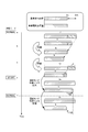
- 3 and 4 are diagrams for explaining a procedure for deriving the reference travel distance and the reference electricity consumption amount in the present embodiment.
- the driving mode of the vehicle is switched from the NORMAL mode to the ECON mode, and then switched again to the NORMAL mode.
- the reference travel distance at time point a while traveling in the NORMAL mode is D1, and has reached the compression threshold value Dth.
- a compression process of multiplying the reference travel distance D1 by Ds / D1 is performed, and the reference travel distance D2 at the time point b becomes Ds.
- the reference electricity consumption at time point a is I1
- compression processing is performed by multiplying the reference electricity consumption amount by Ds / D1
- the operation mode is switched from the NORMAL mode to the ECON mode.
- the operation mode switching coefficient 1 / X (where X> 1) corresponding to the switching of the operation mode from the NORMAL mode to the ECON mode.
- the standard electricity consumption is compressed.
- the driver is shown in advance the possibility that the electricity consumption is reduced by switching from the NORMAL mode to the ECON mode, the electricity consumption rate is increased, and the cruising distance is increased. Is possible.
- the operation mode is switched from the ECON mode to the NORMAL mode.
- the reference electric consumption is expanded by multiplying the reference electric consumption by the operation mode switching coefficient X corresponding to the switching of the operation mode from the ECON mode to the NORMAL mode.
- the driver is shown in advance the possibility that the electricity consumption will increase by switching from the ECON mode to the NORMAL mode, the electricity consumption rate will decrease, and consequently the cruising range will be reduced. Is possible.
- the vehicle operation mode is switched from the NORMAL mode to the SPORT mode, and then switched to the NORMAL mode again.
- the reference travel distance at time point a while traveling in the NORMAL mode is D1, and has reached the compression threshold value Dth.
- a compression process of multiplying the reference travel distance D1 by Ds / D1 is performed, and the reference travel distance D2 at the time point b becomes Ds.
- the reference electricity consumption at time point a is I1
- compression processing is performed by multiplying the reference electricity consumption amount by Ds / D1
- the operation mode is switched from the NORMAL mode to the SPORT mode.
- an operation mode switching coefficient Y (where Y> 1) corresponding to the switching of the operation mode from the NORMAL mode to the SPORT mode.
- Electricity consumption is expanded.
- the driver is shown in advance the possibility that the electricity consumption will increase by switching from the NORMAL mode to the SPORT mode, the electricity consumption rate will decrease, and consequently the cruising range will be reduced. Is possible.
- the operation mode is switched from the SPORT mode to the NORMAL mode at the time point f.
- the operation mode switching coefficient 1 / Y corresponding to the switching from the SPORT mode to the NORMAL mode.
- the standard electricity consumption is compressed.
- the driver is shown in advance the possibility that the electricity consumption will decrease by switching from the SPORT mode to the NORMAL mode, the electricity consumption rate will increase, and consequently the cruising distance will increase. Is possible.
- FIGS. 3 and 4 for the sake of simplification, the distance traveled and the amount of electricity consumed are not integrated after switching of the operation mode. However, when traveling or electricity consumption occurs, the values are naturally integrated. 3 and 4, only switching between the NORMAL mode and the ECON mode or between the NORMAL mode and the SPORT mode is shown, but the operation mode is between the ECON mode and the SPORT mode. It may be switched.
- FIG. 5 shows an example of a transmission mode switching coefficient corresponding to switching between the operation modes. As shown in FIG. 5, the operation mode switching coefficient corresponding to switching from the ECON mode to the SPORT mode is XY, and the operation mode switching coefficient corresponding to switching from the SPORT mode to the ECON mode is 1 / XY. These operation mode switching coefficients are determined in advance according to the system output upper limit value of each operation mode and stored in a memory (not shown) or the like.
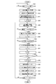
- the management ECU 21 determines whether or not the vehicle system has been activated, for example, whether or not an ignition switch has been turned on (step S1).
- the operation mode switching unit 41 acquires the current operation mode based on information input from the operation mode changeover switch 51 (step S2).
- the reference mileage deriving unit 35 acquires the current reference mileage D stored in the reference mileage storage unit 33, and the reference electricity consumption derivation unit 36 is stored in the reference electricity consumption amount storage unit 34.
- the current reference electricity consumption I is acquired (step S3).
- the reference travel distance deriving unit 35 updates the value of the reference travel distance D to Ds by multiplying the current reference travel distance D by Ds / D.
- the reference electricity consumption amount deriving unit 36 updates the value of the reference electricity consumption amount I by multiplying the current reference electricity consumption amount I by Ds / D (step S4).
- the travel distance acquisition unit 31 acquires the travel distance d from the previous processing time to the current time
- the electricity consumption amount acquisition unit 32 acquires the electric power consumption amount i from the previous processing time to the current time (step S5).
- step S6 determines whether or not the operation mode has been switched between the previous processing and the current time. If it is determined that the operation mode is not switched, the process directly proceeds to step S9.
- the reference electricity consumption amount deriving unit 36 acquires the operation mode switching coefficient fm corresponding to the content of the operation mode switching by the operation mode switching unit 41 from the memory or the like. (Step S7). Then, the reference electricity consumption amount deriving unit 36 updates the value of the reference electricity consumption amount I by multiplying the current reference electricity consumption amount I by the operation mode switching coefficient fm (step S8).
- the reference travel distance deriving unit 35 adds the travel distance d to the reference travel distance D and updates the value of the reference travel distance D.
- the reference electricity consumption amount deriving unit 36 adds the electricity consumption amount i to the current reference electricity consumption amount I, and updates the value of the reference electricity consumption amount I (step S9).
- the reference mileage deriving unit 35 determines whether or not the updated reference mileage D ⁇ compression threshold Dth (step S10). When it is determined in step S10 that the reference travel distance D ⁇ the compression threshold Dth, the reference travel distance deriving unit 35 multiplies the current reference travel distance D by Ds / D to obtain the value of the reference travel distance D. Is updated to Ds. Similarly, the reference electricity consumption amount deriving unit 36 updates the value of the reference electricity consumption amount I by multiplying the current reference electricity consumption amount I by Ds / D (step S11).
- the electricity consumption rate deriving unit 37 sets the reference travel distance D as the reference electrical distance D. By dividing by the consumption amount I, the electricity consumption rate R is derived (step S12).
- the battery usable capacity acquisition unit 38 acquires the usable capacity W of the battery 13 (step S13).
- the cruising range deriving unit 39 derives the cruising range C by multiplying the usable capacity W of the battery 13 by the electricity consumption rate R (step S14).
- the derived cruising range C is displayed on the cruising range display unit 50 (step S15).
- Management ECU21 judges whether the vehicle system was complete
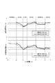
- FIG. 7 is a chart showing the effect of the control device according to the present embodiment.
- the solid line in FIG. 7 shows the calculation result of the electricity consumption rate and the cruising distance when the reference electricity consumption is instantaneously expanded or compressed in accordance with the switching of the operation mode between the NORMAL mode and the ECON mode. .
- the broken line in FIG. 7 shows the calculation result of the electricity consumption rate and the cruising range when the processing according to the switching of the operation mode is not performed.
- the travel distance reaches p (km), r (km), and t (km
- the operation mode is switched from the NORMAL mode to the ECON mode.
- electricity consumption is compressed at these points in time (solid line in FIG.
- both the electricity consumption rate and the cruising distance both increase to a certain extent, and the electricity consumption rate and cruising distance can be reduced by switching the operation mode.
- the driver is shown to be improving.
- the operation mode is switched from the ECON mode to the NORMAL mode.
- the electricity consumption is increased at these points (solid line in FIG. 7), both the electricity consumption rate and the cruising range are decreased, and the processing according to the switching of the operation mode is not performed (FIG. 7). It turns out that it returns to a value almost the same as the broken line in the middle).
- the compression processing is performed when the reference mileage or the reference energy consumption increases as the vehicle travels. Consumption can be kept constant. As a result, it is possible to derive an energy consumption rate that appropriately reflects the change in the driving condition while keeping the influence of the change in the driving condition constant. In addition, when there is switching between operation modes having different system output upper limit values, an energy consumption rate that appropriately reflects the switching can be derived. Therefore, according to the vehicle control device of the present embodiment, the energy consumption rate reflecting the switching of the driving mode, and thus the cruising range can be shown to the driver in advance, so that convenience can be improved. Can satisfy the driver's interest.
- the air conditioner 14 that is driven and operated by the power of the battery 13 according to the operation of the user, the temperature in the vehicle compartment, etc. performs air conditioning in the vehicle compartment. That is, since the amount of electricity consumed varies depending on the operating state of the air conditioner 14, the influence of the change in the operating state of the air conditioner 14 on the electricity consumption rate, and hence the cruising range is great. Therefore, in this modification, in addition to compressing or expanding the reference electricity consumption according to the switching of the operation mode, the reference electricity consumption is also compressed or enlarged according to a change in the operating state of the air conditioner 14. .
- FIG. 8 is a diagram for explaining a procedure for deriving the reference mileage and the reference electricity consumption in this modification.
- the reference travel distance is D1
- the compression threshold value Dth is reached.
- a compression process of multiplying the reference travel distance D1 by Ds / D1 is performed, and the reference travel distance D2 at the time point b becomes Ds.
- the reference electricity consumption at time point a is I1
- compression processing is performed by multiplying the reference electricity consumption amount by Ds / D1
- the air conditioner 14 changes from the operating state to the non-operating state (A / C OFF) at the time point f, the A / C operating state coefficient 1 corresponding to the change from the operating state of the air conditioner 14 to the non-operating state.
- the reference electricity consumption is compressed.
- the possibility that the effect that the air consumption device 14 is changed to the non-operating state, the electricity consumption is reduced, the electricity consumption rate is increased, and the cruising distance is increased can be obtained. Can be shown in advance.
- the operation mode and the switching thereof are omitted for simplification, but in the present modification, the reference electric power is changed according to both the change in the operating state of the air conditioner 14 and the switching of the operation mode. It is possible to compress or expand the consumption.
- standard electric consumption was expanded or compressed according to the switching between the non-operation state of the air conditioning apparatus 14, and an operation state, it is not restricted to this.
- the reference electricity consumption may be expanded or compressed by multiplying by an A / C operating state coefficient corresponding to a change in the temperature or air volume setting of the air conditioner 14. These A / C operation state coefficients are determined in advance based on the performance of the air conditioner 14 and stored in a memory (not shown).
- the management ECU 21 determines whether or not the vehicle system has been activated, for example, whether or not an ignition switch has been turned on (step S21).
- the operation mode switching unit 41 acquires the current operation mode based on information input from the operation mode switch 51 (step S22), and an A / C operation state acquisition unit. 42 acquires the operating state of the air conditioner 14 (step S23).
- the reference mileage deriving unit 35 acquires the current reference mileage D stored in the reference mileage storage unit 33, and the reference electricity consumption derivation unit 36 is stored in the reference electricity consumption amount storage unit 34.
- the current reference electricity consumption I is acquired (step S24).
- the reference travel distance deriving unit 35 updates the value of the reference travel distance D to Ds by multiplying the current reference travel distance D by Ds / D.
- the reference electricity consumption amount deriving unit 36 updates the value of the reference electricity consumption amount I by multiplying the current reference electricity consumption amount I by Ds / D (step S25).
- the travel distance acquisition unit 31 acquires the travel distance d from the previous processing to the current time
- the electricity consumption acquisition unit 32 acquires the electric consumption i from the previous processing to the current time (step S26).
- the operation mode switching unit 41 determines whether or not the operation mode has been switched between the previous processing and the current time (step S27). If it is determined that there is no switching of the operation mode, the process directly proceeds to step S30.
- the reference electricity consumption amount deriving unit 36 sets the operation mode switching coefficient fm corresponding to the content of the operation mode switching by the operation mode switching unit 41 to a memory (not shown) or the like. (Step S28). Then, the value of the reference electricity consumption I is updated by multiplying the current reference electricity consumption I by the operation mode switching coefficient fm (step S29).
- step S30 the A / C operating state acquisition unit 42 determines whether or not the operating state of the air conditioner 14 has changed between the previous processing and the current time (step S30). If it is determined that there is no change in the operating state of the air conditioner 14, the process proceeds directly to step S33.
- the reference electricity consumption deriving unit 36 determines the change in the operating state of the air conditioner 14 acquired by the A / C operating state acquiring unit 42.
- the corresponding A / C operation state coefficient fa is acquired from a memory (not shown) or the like (step S31).
- the value of the reference electricity consumption I is updated by multiplying the reference electricity consumption I by the A / C operating state coefficient fa (step S32).
- the reference travel distance deriving unit 35 adds the travel distance d to the reference travel distance D and updates the value of the reference travel distance D.
- the reference electricity consumption amount deriving unit 36 adds the electricity consumption amount i to the current reference electricity consumption amount I, and updates the value of the reference electricity consumption amount I (step S33).
- the subsequent processes in steps S34 to S40 are the same as those in steps S10 to S16 in FIG.
- the energy consumption rate reflecting the change can be derived. Therefore, according to the vehicle control device according to this modification, the energy consumption rate reflecting the change in the operating state of the air conditioner and the switching of the operation mode, and thus the cruising distance can be shown in advance to the driver. Can be improved.
- the present invention is not limited to the above-described embodiments and modifications, and can be appropriately modified and improved.
- the control device according to the present invention is mounted on an electric vehicle.
- the control device according to the present invention is based on the driving force of an electric motor and / or heat engine according to the running state of the vehicle.
- the present invention may be applied to a traveling HEV (Hybrid Electrical Vehicle).
- HEV Hybrid Electrical Vehicle
- the HEV is used only for power generation by the internal combustion engine, and the electric power generated by the driving force of the internal combustion engine is charged to the capacitor or the series type HEV supplied to the motor is used for the electric motor and the internal combustion engine.
- the present invention may be a parallel-type HEV that travels by at least one of the driving forces, or a series-parallel switching type HEV that combines both types. Further, the present invention is applicable to vehicles such as PHEV (Plugin Hybrid Electric Vehicle), FCV (Fuel Cell Vehicle: Fuel Cell Vehicle), PFCV (Plugin Fuel Cell Vehicle: Plugin Fuel Cell Vehicle), etc. Is applicable.
- the present invention can also be applied to a conventional vehicle that travels by driving a heat engine such as an internal combustion engine by supplying fuel such as gasoline.
- the compression processing is performed such that the reference mileage that is the basis for deriving the electricity consumption rate is maintained within a predetermined range.
- the reference electricity that is the basis for deriving the electricity consumption rate is used. You may perform the compression process which maintains the value of consumption within the predetermined range. Further, when the electricity consumption is reduced to less than a predetermined value due to regeneration, further enlargement processing may be performed. In this case as well, by compressing or expanding the reference mileage according to changes in the operating state of the air conditioner, switching of operation modes, etc., the electricity consumption rate that appropriately reflects these changes and switching, and thus cruising is possible. The distance can be calculated. Further, the operation modes having different system output upper limit values need not be three, and may be two, or four or more.
- Electric vehicles (vehicles) 11 motor 13 battery 14 air conditioner (A / C) 21 Management ECU 31 Travel Distance Acquisition Unit 32 Electricity Consumption Acquisition Unit 35 Reference Travel Distance Derivation Unit 36 Reference Electricity Consumption Derivation Unit 37 Electricity Consumption Rate Derivation Unit 38 Battery Usable Capacity Acquisition Unit 39 Cruising Range Derivation Unit 41 Operation Mode Switching Unit 42 A / C operation state acquisition unit 50 cruising range display unit 51 operation mode switch
Abstract
Description
航続可能距離C(km)=電気消費率R(km/Ah)×使用可能容量W(Ah)
ここで、航続可能距離は、現在の走行状況が継続された場合に、現在のバッテリ13の電力のみを用いて走行可能な残存距離を意味する。前述したように、バッテリ13の使用可能容量は、バッテリ使用可能容量取得部38によりリアルタイムで取得されるため、現在の走行状況に応じた電気消費率Rを導出することができれば、現在の走行状況に応じた航続可能距離Cを導出することが可能である。
電気消費率R(km/Ah)=基準走行距離D(km)/基準電気消費量I(Ah)
前述したように、基準走行距離Dおよび基準電気消費量Iは基準走行距離記憶部33および基準消費電気量記憶部34にそれぞれ記憶されており、走行距離取得部31および電気消費量取得部32によりリアルタイムで取得される値が随時積算されている。
上記した車両10において、前述したように、使用者の操作や車室内の温度等に応じて、バッテリ13の電力によって駆動されて作動した空調装置14が、車室内の冷暖房等を行なう。すなわち、空調装置14の作動状態によって電気消費量が変化するため、空調装置14の作動状態の変化が電気消費率に及ぼす影響、ひいては航続可能距離に及ぼす影響は大きい。そこで、本変形例では、運転モードの切替に応じて基準電気消費量の圧縮または拡大を行なうことに加え、空調装置14の作動状態の変化に応じても基準電気消費量の圧縮または拡大を行なう。
11 モータ
13 バッテリ
14 空調装置(A/C)
21 マネジメントECU
31 走行距離取得部
32 電気消費量取得部
35 基準走行距離導出部
36 基準電気消費量導出部
37 電気消費率導出部
38 バッテリ使用可能容量取得部
39 航続可能距離導出部
41 運転モード切替部
42 A/C作動状態取得部
50 航続可能距離表示部
51 運転モード切替スイッチ
Claims (5)
- 少なくとも1つのエネルギー源から供給されるエネルギーにより駆動されて走行する車両の制御装置であって、
前記車両の走行距離を取得する走行距離取得部と、
前記走行距離を積算して基準走行距離を導出する基準走行距離導出部と、
前記車両のエネルギー消費量を取得するエネルギー消費量取得部と、
前記エネルギー消費量を積算して基準エネルギー消費量を導出する基準エネルギー消費量導出部と、
前記基準走行距離と前記基準エネルギー消費量とに基づいて、エネルギー消費率を導出するエネルギー消費率導出部と、
第1運転モードと、前記第1運転モードよりシステム出力上限値が低く設定される第2運転モードと、前記第2運転モードよりもシステム出力上限値が低く設定される第3運転モードと、を少なくとも含む複数の運転モードを切り替える運転モード切替部と、を備え、
前記運転モード切替部がいずれか1つの運転モードから他の運転モードへと運転モードを切替えた時点で、前記基準エネルギー消費量導出部が、前記切替に対応する運転モード変更係数を基準エネルギー消費量に乗算することにより基準エネルギー消費量を圧縮または拡大する制御装置。 - 前記基準走行距離が所定の走行距離上限値に到達した時点で、
前記基準走行距離導出部は、前記基準走行距離に圧縮係数を乗算することにより、前記基準走行距離を所定の走行距離下限値へと圧縮し、
前記基準走行距離導出部が前記基準走行距離を圧縮する際に、前記基準エネルギー消費量導出部は、前記圧縮係数を前記基準エネルギー消費量に乗算することにより前記基準エネルギー消費量を圧縮する、請求項1に記載の制御装置。 - 空調装置をさらに備え、
前記基準エネルギー消費量導出部は、前記空調装置の作動状態の変化に対応する空調作動係数を基準エネルギー消費量に乗算することにより、基準エネルギー消費量を圧縮または拡大する請求項1または請求項2に記載の制御装置。 - 前記エネルギー源から供給可能なエネルギー残量を取得するエネルギー残量取得部と、
前記エネルギー残量と、前記エネルギー消費率と、に基づき、車両の航続可能距離を導出する航続可能距離導出部と、
前記航続可能距離を表示部に表示する表示処理部と、を更に備える、請求項1~3のいずれか1項に記載の制御装置。 - 少なくとも1つのエネルギー源から供給されるエネルギーにより駆動されて走行し、第1運転モードと、前記第1運転モードよりエネルギー消費率及び航続可能距離が向上する第2運転モードと、の少なくとも2つの運転モードを有する車両の航続可能距離表示方法であって、
前記第1運転モードから前記第2運転モードに切り替えた場合、切り替え直前の前記第2運転モードにおける航続可能距離を基準として増加方向にオフセットした値を前記第2運転モードにおける航続可能距離の初期値とする第1の瞬時切り替えを行い、前記第2運転モードに切り替えた後で前記初期値を表示し、前記第2運転モードにおける消費エネルギーに基づき航続可能距離を前記初期値から連続的に変化させて表示することと、
前記第2運転モードから前記第1運転モードに切り替えた場合、切り替え直前の前記第2運転モードにおける航続可能距離を基準として減少方向にオフセットした値を前記第1運転モードにおける航続可能距離の初期値とする第2の瞬時切り替えを行い、前記第1運転モードに切り替えた後で前記初期値を表示し、前記第1運転モードにおける消費エネルギーに基づき航続可能距離を前記初期値から連続的に変化させて表示することと、の少なくともいずれかを実行し、
前記第1又は第2の瞬時切り替えを行った後で表示される航続可能距離が、走行距離の増加に伴い、瞬時切り替えを実行しなかった場合に表示される航続可能距離へと近づくことを特徴とする航続可能距離表示方法。
Priority Applications (3)
| Application Number | Priority Date | Filing Date | Title |
|---|---|---|---|
| US14/239,486 US9340112B2 (en) | 2011-09-05 | 2012-09-05 | Control apparatus for vehicle with different driving modes |
| DE112012003691.3T DE112012003691T5 (de) | 2011-09-05 | 2012-09-05 | Fahrzeugsteuerungsvorrichtung |
| JP2013532613A JP5775934B2 (ja) | 2011-09-05 | 2012-09-05 | 車両の制御装置 |
Applications Claiming Priority (2)
| Application Number | Priority Date | Filing Date | Title |
|---|---|---|---|
| JP2011-193083 | 2011-09-05 | ||
| JP2011193083 | 2011-09-05 |
Publications (1)
| Publication Number | Publication Date |
|---|---|
| WO2013035711A1 true WO2013035711A1 (ja) | 2013-03-14 |
Family
ID=47832156
Family Applications (1)
| Application Number | Title | Priority Date | Filing Date |
|---|---|---|---|
| PCT/JP2012/072537 WO2013035711A1 (ja) | 2011-09-05 | 2012-09-05 | 車両の制御装置 |
Country Status (4)
| Country | Link |
|---|---|
| US (1) | US9340112B2 (ja) |
| JP (1) | JP5775934B2 (ja) |
| DE (1) | DE112012003691T5 (ja) |
| WO (1) | WO2013035711A1 (ja) |
Cited By (3)
| Publication number | Priority date | Publication date | Assignee | Title |
|---|---|---|---|---|
| JP2012217259A (ja) * | 2011-03-31 | 2012-11-08 | Honda Motor Co Ltd | 車両の制御装置 |
| CN110281812A (zh) * | 2019-06-27 | 2019-09-27 | 一汽解放汽车有限公司 | 一种基于工况识别的续航里程估算系统 |
| CN113586707A (zh) * | 2021-07-09 | 2021-11-02 | 北京汽车股份有限公司 | 一种车辆档位控制方法、装置、设备、车辆及存储介质 |
Families Citing this family (5)
| Publication number | Priority date | Publication date | Assignee | Title |
|---|---|---|---|---|
| JP5845930B2 (ja) * | 2012-01-27 | 2016-01-20 | トヨタ自動車株式会社 | 少なくとも電動機を用いて走行可能な車両の電動走行可能距離表示装置 |
| US9266611B2 (en) * | 2013-06-20 | 2016-02-23 | University Of Florida Research Foundation, Inc. | Flight path development for remote sensing vehicles in a moving reference frame |
| KR20180101004A (ko) * | 2017-03-03 | 2018-09-12 | 현대자동차주식회사 | 차량 및 차량의 제어방법 |
| CN110525318A (zh) * | 2019-10-08 | 2019-12-03 | 安徽江淮汽车集团股份有限公司 | 电动冷藏车控制系统及电动冷藏车 |
| CN113071506B (zh) * | 2021-05-20 | 2022-04-05 | 吉林大学 | 考虑座舱温度的燃料电池汽车能耗优化系统 |
Citations (7)
| Publication number | Priority date | Publication date | Assignee | Title |
|---|---|---|---|---|
| JPS56140216A (en) * | 1980-04-03 | 1981-11-02 | Nippon Denso Co Ltd | Navigable distance indication method for vehicle |
| JPS602301U (ja) * | 1983-06-17 | 1985-01-09 | 日産自動車株式会社 | 電気自動車の走行可能距離表示装置 |
| JPH08126103A (ja) * | 1994-10-21 | 1996-05-17 | Honda Motor Co Ltd | 自動車用表示装置 |
| JPH09191505A (ja) * | 1995-12-28 | 1997-07-22 | Yazaki Corp | 電気自動車の走行可能距離算出装置 |
| JP2007298491A (ja) * | 2006-04-07 | 2007-11-15 | Fuji Heavy Ind Ltd | 車両用表示装置 |
| JP2010226795A (ja) * | 2009-03-19 | 2010-10-07 | Fuji Heavy Ind Ltd | 電気自動車の制御装置 |
| WO2012063630A1 (ja) * | 2010-11-10 | 2012-05-18 | 本田技研工業株式会社 | 電動車両 |
Family Cites Families (6)
| Publication number | Priority date | Publication date | Assignee | Title |
|---|---|---|---|---|
| JP3990716B1 (ja) | 2006-04-07 | 2007-10-17 | 富士重工業株式会社 | 車両用表示装置 |
| US7669676B2 (en) * | 2006-10-24 | 2010-03-02 | Larry D. Miller Trust | Hybrid propulsion system and method for its operation |
| US8423219B2 (en) * | 2010-03-18 | 2013-04-16 | Toyota Jidosha Kabushiki Kaisha | Electric drive vehicle |
| JP5362760B2 (ja) | 2011-03-31 | 2013-12-11 | 本田技研工業株式会社 | 車両の制御装置 |
| US9272701B2 (en) * | 2011-12-28 | 2016-03-01 | Toyota Jidosha Kabushiki Kaisha | Plug-in hybrid vehicle |
| JP5549726B2 (ja) * | 2012-11-22 | 2014-07-16 | 三菱自動車工業株式会社 | 航続距離演算装置 |
-
2012
- 2012-09-05 DE DE112012003691.3T patent/DE112012003691T5/de not_active Withdrawn
- 2012-09-05 JP JP2013532613A patent/JP5775934B2/ja not_active Expired - Fee Related
- 2012-09-05 US US14/239,486 patent/US9340112B2/en active Active
- 2012-09-05 WO PCT/JP2012/072537 patent/WO2013035711A1/ja active Application Filing
Patent Citations (7)
| Publication number | Priority date | Publication date | Assignee | Title |
|---|---|---|---|---|
| JPS56140216A (en) * | 1980-04-03 | 1981-11-02 | Nippon Denso Co Ltd | Navigable distance indication method for vehicle |
| JPS602301U (ja) * | 1983-06-17 | 1985-01-09 | 日産自動車株式会社 | 電気自動車の走行可能距離表示装置 |
| JPH08126103A (ja) * | 1994-10-21 | 1996-05-17 | Honda Motor Co Ltd | 自動車用表示装置 |
| JPH09191505A (ja) * | 1995-12-28 | 1997-07-22 | Yazaki Corp | 電気自動車の走行可能距離算出装置 |
| JP2007298491A (ja) * | 2006-04-07 | 2007-11-15 | Fuji Heavy Ind Ltd | 車両用表示装置 |
| JP2010226795A (ja) * | 2009-03-19 | 2010-10-07 | Fuji Heavy Ind Ltd | 電気自動車の制御装置 |
| WO2012063630A1 (ja) * | 2010-11-10 | 2012-05-18 | 本田技研工業株式会社 | 電動車両 |
Cited By (4)
| Publication number | Priority date | Publication date | Assignee | Title |
|---|---|---|---|---|
| JP2012217259A (ja) * | 2011-03-31 | 2012-11-08 | Honda Motor Co Ltd | 車両の制御装置 |
| CN110281812A (zh) * | 2019-06-27 | 2019-09-27 | 一汽解放汽车有限公司 | 一种基于工况识别的续航里程估算系统 |
| CN113586707A (zh) * | 2021-07-09 | 2021-11-02 | 北京汽车股份有限公司 | 一种车辆档位控制方法、装置、设备、车辆及存储介质 |
| CN113586707B (zh) * | 2021-07-09 | 2023-03-03 | 北京汽车股份有限公司 | 一种车辆档位控制方法、装置、设备、车辆及存储介质 |
Also Published As
| Publication number | Publication date |
|---|---|
| JPWO2013035711A1 (ja) | 2015-03-23 |
| JP5775934B2 (ja) | 2015-09-09 |
| US20140180565A1 (en) | 2014-06-26 |
| DE112012003691T5 (de) | 2014-07-10 |
| US9340112B2 (en) | 2016-05-17 |
Similar Documents
| Publication | Publication Date | Title |
|---|---|---|
| JP5775934B2 (ja) | 車両の制御装置 | |
| US8655532B2 (en) | System and method for operating a hybrid vehicle | |
| US9352739B2 (en) | Method for operating a hybrid vehicle | |
| CN204236461U (zh) | 用于控制混合动力车(hev)所用动力系统的系统 | |
| US9145048B2 (en) | Apparatus for hybrid engine control and method of manufacture same | |
| US9340121B2 (en) | Method and system for heating a vehicle battery | |
| JP5926182B2 (ja) | ユーザ入力に基づくハイブリッド車のモータ補助 | |
| US8653960B2 (en) | Vehicle gauge for displaying electric mode status and method of doing the same | |
| US9971865B2 (en) | Method for operating a hybrid vehicle | |
| US8918240B2 (en) | Method for operating hybrid vehicle | |
| WO2013031491A1 (ja) | ハイブリッド車両の制御装置 | |
| JP6156419B2 (ja) | 車両 | |
| JP2018509880A (ja) | 自動車の中の電池のエネルギー状態の値を決定するための方法及び装置 | |
| CN109466537B (zh) | 车辆和用于控制车辆的方法 | |
| CN104512410A (zh) | 四驱混合动力汽车的控制方法 | |
| CN104691541A (zh) | 具有三种模式耗尽策略的混合动力传动系及其操作方法 | |
| JP2013056613A (ja) | 電気自動車の電力供給制御装置 | |
| KR102359578B1 (ko) | 하이브리드 차량의 최적 운전점 결정 방법 | |
| US10836276B2 (en) | Display device | |
| US10124679B2 (en) | Method and apparatus for recharging an energy storage device on a vehicle | |
| CN109532560A (zh) | 混合动力汽车的控制方法、设备、存储介质及装置 | |
| Hellström et al. | Management of kinetic and electric energy in heavy trucks | |
| JP2011166876A (ja) | 車両用制御装置および車両用制御方法 | |
| JP5362760B2 (ja) | 車両の制御装置 | |
| KR20140071593A (ko) | 하이브리드 차량의 충전 제어 방법 |
Legal Events
| Date | Code | Title | Description |
|---|---|---|---|
| 121 | Ep: the epo has been informed by wipo that ep was designated in this application |
Ref document number: 12830418 Country of ref document: EP Kind code of ref document: A1 |
|
| ENP | Entry into the national phase |
Ref document number: 2013532613 Country of ref document: JP Kind code of ref document: A |
|
| WWE | Wipo information: entry into national phase |
Ref document number: 14239486 Country of ref document: US |
|
| WWE | Wipo information: entry into national phase |
Ref document number: 1120120036913 Country of ref document: DE Ref document number: 112012003691 Country of ref document: DE |
|
| 122 | Ep: pct application non-entry in european phase |
Ref document number: 12830418 Country of ref document: EP Kind code of ref document: A1 |