WO2013035374A1 - 超音波内視鏡 - Google Patents
超音波内視鏡 Download PDFInfo
- Publication number
- WO2013035374A1 WO2013035374A1 PCT/JP2012/060558 JP2012060558W WO2013035374A1 WO 2013035374 A1 WO2013035374 A1 WO 2013035374A1 JP 2012060558 W JP2012060558 W JP 2012060558W WO 2013035374 A1 WO2013035374 A1 WO 2013035374A1
- Authority
- WO
- WIPO (PCT)
- Prior art keywords
- cable
- housing
- unit
- ultrasonic
- shield case
- Prior art date
Links
Images


Classifications
-
- A—HUMAN NECESSITIES
- A61—MEDICAL OR VETERINARY SCIENCE; HYGIENE
- A61B—DIAGNOSIS; SURGERY; IDENTIFICATION
- A61B8/00—Diagnosis using ultrasonic, sonic or infrasonic waves
- A61B8/44—Constructional features of the ultrasonic, sonic or infrasonic diagnostic device
- A61B8/4444—Constructional features of the ultrasonic, sonic or infrasonic diagnostic device related to the probe
- A61B8/445—Details of catheter construction
-
- A—HUMAN NECESSITIES
- A61—MEDICAL OR VETERINARY SCIENCE; HYGIENE
- A61B—DIAGNOSIS; SURGERY; IDENTIFICATION
- A61B1/00—Instruments for performing medical examinations of the interior of cavities or tubes of the body by visual or photographical inspection, e.g. endoscopes; Illuminating arrangements therefor
- A61B1/00064—Constructional details of the endoscope body
- A61B1/00071—Insertion part of the endoscope body
- A61B1/0008—Insertion part of the endoscope body characterised by distal tip features
- A61B1/00094—Suction openings
-
- A—HUMAN NECESSITIES
- A61—MEDICAL OR VETERINARY SCIENCE; HYGIENE
- A61B—DIAGNOSIS; SURGERY; IDENTIFICATION
- A61B1/00—Instruments for performing medical examinations of the interior of cavities or tubes of the body by visual or photographical inspection, e.g. endoscopes; Illuminating arrangements therefor
- A61B1/00064—Constructional details of the endoscope body
- A61B1/0011—Manufacturing of endoscope parts
-
- A—HUMAN NECESSITIES
- A61—MEDICAL OR VETERINARY SCIENCE; HYGIENE
- A61B—DIAGNOSIS; SURGERY; IDENTIFICATION
- A61B1/00—Instruments for performing medical examinations of the interior of cavities or tubes of the body by visual or photographical inspection, e.g. endoscopes; Illuminating arrangements therefor
- A61B1/00112—Connection or coupling means
- A61B1/00114—Electrical cables in or with an endoscope
-
- A—HUMAN NECESSITIES
- A61—MEDICAL OR VETERINARY SCIENCE; HYGIENE
- A61B—DIAGNOSIS; SURGERY; IDENTIFICATION
- A61B1/00—Instruments for performing medical examinations of the interior of cavities or tubes of the body by visual or photographical inspection, e.g. endoscopes; Illuminating arrangements therefor
- A61B1/00163—Optical arrangements
- A61B1/00174—Optical arrangements characterised by the viewing angles
- A61B1/00177—Optical arrangements characterised by the viewing angles for 90 degrees side-viewing
-
- A—HUMAN NECESSITIES
- A61—MEDICAL OR VETERINARY SCIENCE; HYGIENE
- A61B—DIAGNOSIS; SURGERY; IDENTIFICATION
- A61B1/00—Instruments for performing medical examinations of the interior of cavities or tubes of the body by visual or photographical inspection, e.g. endoscopes; Illuminating arrangements therefor
- A61B1/005—Flexible endoscopes
-
- A—HUMAN NECESSITIES
- A61—MEDICAL OR VETERINARY SCIENCE; HYGIENE
- A61B—DIAGNOSIS; SURGERY; IDENTIFICATION
- A61B1/00—Instruments for performing medical examinations of the interior of cavities or tubes of the body by visual or photographical inspection, e.g. endoscopes; Illuminating arrangements therefor
- A61B1/06—Instruments for performing medical examinations of the interior of cavities or tubes of the body by visual or photographical inspection, e.g. endoscopes; Illuminating arrangements therefor with illuminating arrangements
- A61B1/07—Instruments for performing medical examinations of the interior of cavities or tubes of the body by visual or photographical inspection, e.g. endoscopes; Illuminating arrangements therefor with illuminating arrangements using light-conductive means, e.g. optical fibres
-
- A—HUMAN NECESSITIES
- A61—MEDICAL OR VETERINARY SCIENCE; HYGIENE
- A61B—DIAGNOSIS; SURGERY; IDENTIFICATION
- A61B8/00—Diagnosis using ultrasonic, sonic or infrasonic waves
- A61B8/12—Diagnosis using ultrasonic, sonic or infrasonic waves in body cavities or body tracts, e.g. by using catheters
-
- A—HUMAN NECESSITIES
- A61—MEDICAL OR VETERINARY SCIENCE; HYGIENE
- A61B—DIAGNOSIS; SURGERY; IDENTIFICATION
- A61B8/00—Diagnosis using ultrasonic, sonic or infrasonic waves
- A61B8/44—Constructional features of the ultrasonic, sonic or infrasonic diagnostic device
- A61B8/4483—Constructional features of the ultrasonic, sonic or infrasonic diagnostic device characterised by features of the ultrasound transducer
- A61B8/4494—Constructional features of the ultrasonic, sonic or infrasonic diagnostic device characterised by features of the ultrasound transducer characterised by the arrangement of the transducer elements
-
- A—HUMAN NECESSITIES
- A61—MEDICAL OR VETERINARY SCIENCE; HYGIENE
- A61B—DIAGNOSIS; SURGERY; IDENTIFICATION
- A61B1/00—Instruments for performing medical examinations of the interior of cavities or tubes of the body by visual or photographical inspection, e.g. endoscopes; Illuminating arrangements therefor
- A61B1/00064—Constructional details of the endoscope body
- A61B1/00071—Insertion part of the endoscope body
- A61B1/0008—Insertion part of the endoscope body characterised by distal tip features
- A61B1/00096—Optical elements
-
- A—HUMAN NECESSITIES
- A61—MEDICAL OR VETERINARY SCIENCE; HYGIENE
- A61B—DIAGNOSIS; SURGERY; IDENTIFICATION
- A61B1/00—Instruments for performing medical examinations of the interior of cavities or tubes of the body by visual or photographical inspection, e.g. endoscopes; Illuminating arrangements therefor
- A61B1/00112—Connection or coupling means
- A61B1/00117—Optical cables in or with an endoscope
-
- A—HUMAN NECESSITIES
- A61—MEDICAL OR VETERINARY SCIENCE; HYGIENE
- A61B—DIAGNOSIS; SURGERY; IDENTIFICATION
- A61B1/00—Instruments for performing medical examinations of the interior of cavities or tubes of the body by visual or photographical inspection, e.g. endoscopes; Illuminating arrangements therefor
- A61B1/00112—Connection or coupling means
- A61B1/00119—Tubes or pipes in or with an endoscope
-
- A—HUMAN NECESSITIES
- A61—MEDICAL OR VETERINARY SCIENCE; HYGIENE
- A61B—DIAGNOSIS; SURGERY; IDENTIFICATION
- A61B1/00—Instruments for performing medical examinations of the interior of cavities or tubes of the body by visual or photographical inspection, e.g. endoscopes; Illuminating arrangements therefor
- A61B1/04—Instruments for performing medical examinations of the interior of cavities or tubes of the body by visual or photographical inspection, e.g. endoscopes; Illuminating arrangements therefor combined with photographic or television appliances
- A61B1/05—Instruments for performing medical examinations of the interior of cavities or tubes of the body by visual or photographical inspection, e.g. endoscopes; Illuminating arrangements therefor combined with photographic or television appliances characterised by the image sensor, e.g. camera, being in the distal end portion
-
- A—HUMAN NECESSITIES
- A61—MEDICAL OR VETERINARY SCIENCE; HYGIENE
- A61B—DIAGNOSIS; SURGERY; IDENTIFICATION
- A61B1/00—Instruments for performing medical examinations of the interior of cavities or tubes of the body by visual or photographical inspection, e.g. endoscopes; Illuminating arrangements therefor
- A61B1/12—Instruments for performing medical examinations of the interior of cavities or tubes of the body by visual or photographical inspection, e.g. endoscopes; Illuminating arrangements therefor with cooling or rinsing arrangements
-
- A—HUMAN NECESSITIES
- A61—MEDICAL OR VETERINARY SCIENCE; HYGIENE
- A61B—DIAGNOSIS; SURGERY; IDENTIFICATION
- A61B8/00—Diagnosis using ultrasonic, sonic or infrasonic waves
- A61B8/44—Constructional features of the ultrasonic, sonic or infrasonic diagnostic device
- A61B8/4483—Constructional features of the ultrasonic, sonic or infrasonic diagnostic device characterised by features of the ultrasound transducer
Definitions
- the present invention relates to an ultrasonic endoscope.
- ultrasonic endoscope apparatuses have been widely used in the medical field.
- an ultrasonic probe that transmits and receives ultrasonic waves is provided at the distal end of an elongated endoscope insertion portion.
- the ultrasonic endoscope apparatus transmits ultrasonic waves from the ultrasonic probe, and generates and displays an ultrasonic image of the subject from the ultrasonic echo signal received from the subject.
- a transducer unit having a vibration part is arranged in the housing. Further, since the insertion portion is inserted into the subject, the vibrator unit is provided in a grounded shield case in consideration of electrical safety with respect to the subject, noise countermeasures, and the like.
- the vibrator unit to which the elongated cable unit is connected is stored in the shield case.
- the distal end unit of the ultrasonic endoscope is assembled by storing the transducer unit connected to the elongated cable unit so as to be pushed into the housing.
- the vibrator unit housed in the shield case is housed in the housing at the distal end portion of the insertion portion.
- Japanese Patent Application Laid-Open No. 2009-240755 proposes and discloses a technique of providing a high thermal conductive layer at the tip.
- the vibrator unit when assembling the vibrator unit in the housing, the vibrator unit is fitted into the housing in a state where the cable unit is connected. Specifically, the base end side of the cable unit is pulled out from the cable outlet port of the housing to the outside of the housing, and the vibrator unit connected to the distal end portion of the cable unit is fitted into the housing housing portion so that the vibrator The unit is housed in the housing.
- the opening of the insertion path of the cable unit in the housing storage portion is small, and the recess of the storage portion is not large in the axial direction. For this reason, when an assembly operator fits the vibrator unit into the housing housing, bending stress concentrates on the connection between the vibrator unit and the cable unit, and the signal lines in the cable unit are easily damaged. If it is large, the internal signal line may be disconnected.
- the high thermal conductive layer extending to the base end side is disclosed. No measures are taken against the bending stress concentrated on the connection part of the cable unit.
- the invention of the present application is capable of reducing stress concentration at the connection portion between the transducer unit and the cable unit during assembly of the ultrasonic endoscope and preventing damage to the signal line of the cable, disconnection, etc.
- An object is to provide a sonic endoscope.
- An ultrasonic endoscope has an upper surface, a bottom surface, and a side surface connecting the upper surface and the bottom surface, and an ultrasonic transmission / reception unit that transmits and receives ultrasonic waves on the upper surface side, and the ultrasonic transmission / reception
- a cable connected to the side surface for transmitting and receiving electrical signals to and from the unit, a lead-out port for leading out the cable, and a flexible extension part extending from at least the upper surface side of the lead-out port
- a conductive shield case that covers the side surface and the bottom surface, and a cable insertion path that holds the ultrasonic transmission / reception unit through the shield case and passes the cable and the extension portion into the inside.
- a housing is
- FIG. 5 is a cross-sectional view for explaining a process in which the vibrator unit 2 to which the cable unit 4 is connected according to the first embodiment of the present invention is fitted into the housing 3a of the housing 3.
- FIG. FIG. 3 is a cross-sectional view showing a state in which the vibrator unit 2 is housed in the housing portion 3a of the housing 3 according to the first embodiment of the present invention.
- It is a perspective view of the shield case 5 which has the extension part concerning the modification 1 of the 1st Embodiment of this invention.
- It which looked at the shield case 5 which has the extension part concerning the modification 1 of the 1st Embodiment of this invention from the base end direction.
- FIG. 6 is a cross-sectional view showing a state in which a vibrator unit 2 is housed in a housing portion 3a of a housing 3 according to Modification 2 of the first embodiment of the present invention.
- FIG. 10 is a cross-sectional view showing a state in which the vibrator unit 2 is housed in the housing portion 3a of the housing 3 according to Modification 3 of the first embodiment of the present invention.
- FIG. 10 is a cross-sectional view showing a state in which the vibrator unit 2 is housed in the housing portion 3a of the housing 3 according to Modification 4 of the first embodiment of the present invention. It is a perspective view of the shield case 5 which has the extension part which concerns on the 2nd Embodiment of this invention.
- FIG. 10 is a cross-sectional view for explaining a process in which the vibrator unit 2 to which the cable unit 4 is connected according to the second embodiment of the present invention is fitted into the housing 3a of the housing 3.
- 6 is a cross-sectional view showing a state in which a vibrator unit 2 according to a second embodiment of the present invention is housed in a housing portion 3a of a housing 3.
- FIG. It is a fragmentary sectional view of a vibrator unit with which an imaging unit was installed in a tip hard member. It is the figure seen from the front end side of the insertion part of an ultrasonic endoscope.
- 6 is a partial cross-sectional view of a vibrator unit in which an opening is provided in a part of a shield case 111.
- FIG. 23 is a partial cross-sectional view of the image pickup unit and the light guide unit along the line XXIV-XXIV in FIG. It is an external view which shows the external appearance of the ultrasonic endoscope to which the tube is attached.
- FIG. 26 is a partial cross-sectional view of the mounting clip 201 taken along the line XXVI-XXVI of FIG.
- FIG. 6 is a cross-sectional view showing a state in which an attachment clip 201 is attached to a universal cord 204. It is the figure of the clip 201 for attachment which provided the extension part in the arm part front-end
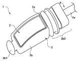
- FIG. 1 and 2 are external views of the distal end unit of the ultrasonic endoscope according to the first embodiment of the present invention.
- FIG. 1 is a perspective view of the front end unit as viewed from diagonally above
- FIG. 2 is a perspective view of the front end unit as viewed from a slightly diagonally rear side
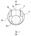
- FIG. 3 is a view of the tip unit 1 as viewed from the front in the axial direction.
- the tip unit 1 mainly includes a vibrator unit 2, a housing 3, a cable unit 4, and a shield case 5 (not shown in FIGS. 1, 2 and 3). .
- the distal end unit 1 is configured such that the vibrator unit 2 is accommodated in the accommodating portion 3 a of the housing 3 and the cable 4 a of the cable unit 4 extends from the proximal end side of the housing 3.
- the distal end unit 1 is provided in the distal end rigid member of the insertion portion of the ultrasonic endoscope, and the endoscope distal end portion is configured.
- the transducer unit 2 which is an ultrasonic transmission / reception unit has an ultrasonic transducer inside. On the upper surface side of the transducer unit 2, an acoustic lens surface 2 a that focuses ultrasonic waves is provided. The lower part of the vibrator unit 2 is housed in a shield case 5 described later.
- the transducer unit 2 has an upper surface, a bottom surface, and a side surface connecting the upper surface and the bottom surface, and constitutes an ultrasonic transmission / reception unit that transmits and receives ultrasonic waves on the upper surface side.
- the housing 3 is made of resin and has a housing main body portion 3b, a protruding portion 3b1 having a flange portion formed at a distal end portion of the housing main body portion 3b, and a base end portion 3b2.
- a cable 4a extends from the base end 3b2.
- the cable 4a is connected to the side surface of the transducer unit 2 in order to transmit and receive electrical signals to and from the transducer unit 2 that is an ultrasonic transmission / reception unit.
- the opening of the housing part 3 a of the housing body 3 b has a shape that follows the shape of the acoustic lens surface 2 a of the transducer unit 2.
- the internal structure of the housing 3 will be described later.
- the ultrasonic transmission / reception unit is described as a convex type, but may be a concave type.
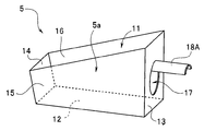
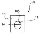
- FIG. 4 is a perspective view of the shield case 5.
- FIG. 5 is a view of the shield case 5 as seen from the proximal direction.
- the shield case 5 has an opening portion 11, a bottom surface portion 12, and four side surface portions 13, 14, 15, and 16.
- the shield case 5 is made of metal, and has a box-like shape that opens upward, in which the area of the opening 11 on the upper surface is larger than the area of the bottom surface 12. Therefore, the storage portion 5 a is formed by the bottom surface portion 12 and the four side surface portions 13, 14, 15, 16.
- the side surface portions 13, 15, 16 on the base end side are orthogonal to the bottom surface portion 12, and the side surface portion 14 on the distal end side has an angle of 90 ° or more with the bottom surface portion 12.
- the shield case 5 is configured. Further, since the height from the bottom surface portion 12 of the side surface portion 13 on the base end side is higher than the height from the bottom surface portion 12 of the side surface portion 14 on the distal end side, the opening 11 is inclined with respect to the bottom surface portion 12. It is formed.
- a lead-out port 17 for leading the cable 4a of the cable unit 4 out of the shield case 5 is formed on the side surface portion 13 on the base end side. As shown in FIG. 5, the outlet 17 is semicircular on the bottom side and rectangular on the top side, and has a size that allows the cable 4a to be inserted.
- a plate-like extending portion 18 extending in the proximal direction is formed on the upper side of the opening 16, that is, on the upper surface side of the outlet port 17, a plate-like extending portion 18 extending in the proximal direction is formed.
- the extending portion 18 is formed at a position where the upper surface of the cable 4 a extending from the transducer unit 1 contacts the lower surface of the extending portion 18 when the transducer unit 2 is stored in the shield case 5. Yes.
- the shield case 5 has a lead-out port 17 for leading out the cable 4a, and a flexible extending portion 18 that extends from at least the upper surface side of the lead-out port 17, and the transducer unit 2 It is a conductive member that covers the side surface and the bottom surface.
- the shield case 5 is manufactured by bending, brazing or the like a single metal plate.
- the extending portion 18 is made of metal and has flexibility, and the shield case 5 and the extending portion 18 are manufactured by bending.
- the extension portion 18 has a length of 1 to 3 mm and a thickness of 0.2 mm.
- the extending portion 18 is preferably made of an elastic material. Examples of the metal having elasticity include copper and phosphor bronze.
- a through hole 14a is provided in the side surface portion 14 on the distal end side of the shield case 5, and the internal grounding wiring is connected to the shield case through the through hole 14a.
- the shield case 5 is configured so that it can be drawn out to the outside and soldered to the ground wiring outside the shield case 5.
- a U-shaped notch is formed in the side surface portion 14 on the tip side as shown by a dotted line in FIG. 6 instead of the circular through hole 14a. May be.
- the wiring portion protrudes from the acoustic lens surface 2a of the transducer unit 2 to the tip side, even if the insulating member in the transducer unit 2 is broken, no current flows through the so-called patient circuit.
- FIG. 6 is a view for explaining housing of the vibrator unit 2 in the shield case 5.
- the vibrator unit 2 according to the present embodiment includes an upper part 2A including an ultrasonic vibrator and an acoustic lens, and a lower part 2B including a circuit board.
- the upper portion 2A is larger than the lower portion 2B, and the lower portion 2B has a shape corresponding to the shape of the storage portion 5a of the shield case 5.
- the base end of the cable 4a of the cable unit 4 is inserted from the inside of the shield case 5 into the outlet port 17, and the cable 4a is connected to the tip of the cable 4a. Pass through the outlet 17. Then, the lower part 2 ⁇ / b> B of the vibrator unit 2 is accommodated in the shield case 5 such that the tip of the cable 4 a is pressed against the inside of the outlet 17. In this way, the lower part 2 ⁇ / b> B of the vibrator unit 2 is housed in the housing part 5 a of the shield case 5.
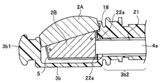
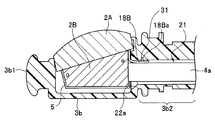
- FIG. 7 is a cross-sectional view for explaining a process in which the vibrator unit 2 to which the cable unit 4 is connected is fitted into the housing 3 a of the housing 3.
- a housing 3a is formed in the housing body 3b of the housing 3 having a substantially cylindrical shape.
- the storage portion 3a is a recess formed in the housing main body portion 3b and has a size capable of storing the vibrator unit 2.
- the base end portion 3b2 is provided with a cable insertion passage 21 that communicates with the storage portion 3a.
- An opening 22 of the cable insertion passage 21 is formed on the proximal end side of the storage portion 3a.
- the opening 22 is formed with a tapered portion 22a for improving the insertion property of the cable 4a.
- the housing 3 has the cable insertion passage 21 that holds the vibrator unit 2 via the shield case 5 and that passes through the cable 4 a and the extension 18.
- the vibrator unit 2 When the vibrator unit 2 is fitted into the housing 3a of the housing 3, first, the base end of the cable 4a is passed from the opening 22 through the cable insertion path 21, the cable 4a is pulled out, the tip of the cable 4a, That is, the connecting portion between the cable unit 4 and the vibrator unit 2 is brought close to the opening 22. And the front-end
- the extension portion 18 contacts and slides on the upper side of the end portion of the opening portion 22, and the base end portion of the extension portion 18 is inserted into the cable from the opening portion 22 of the storage portion 3 a. It is inserted into the passage 21. Furthermore, when the extension part 18 has elasticity, the operator can extend the extension part 18 so that the extension part 18 is naturally drawn into the cable insertion path 21 by the spring property of the extension part 18. Can be inserted into the cable insertion path 21. Moreover, since the taper part 22a is formed in the opening part 22, it is further easy to store.
- the connection part between the cable unit 4 and the vibrator unit 2 is protected by the extending part 18, and the housing 3 of the vibrator unit 2 is housed.
- the bending stress applied to the connecting portion between the cable unit 4 and the vibrator unit 2 when stored in the portion 3a is relieved.
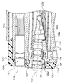
- FIG. 8 is a cross-sectional view showing a state where the vibrator unit 2 is housed in the housing portion 3 a of the housing 3.
- the stress concentration on the connection portion between the transducer unit and the cable unit is reduced, the buckling of the cable end is prevented, and the signal line of the cable is Damage, disconnection, etc. can be prevented. Furthermore, according to the present embodiment described above, the assemblability of the tip unit is improved, the yield is improved, and the cost is reduced.
- a groove into which the plate-like extension part 18 enters is provided along the cable insertion path 21 from the opening 22 of the storage part 3a, and the width of the groove (the width in the direction orthogonal to the axial direction of the cable insertion path 21). ) Is made substantially the same as the width of the extending portion 18 and the extending portion 18 is inserted into the groove, so that the positioning of the vibrator unit 2 around the axis can be reliably performed. That is, the width of the groove provided on the upper surface side of the opening 16 is sized so that the extending part 18 can enter and does not rotate around the axis, whereby the vibrator unit 2 housed in the housing part 3a. It is possible to position around the axis.
- the extension part 18 can take the structure of various modifications, and may have the following structures.
- (Modification 1) 9 and 10 are diagrams for explaining the extending portion according to the first modification.
- FIG. 9 is a perspective view of the shield case 5 having an extending portion according to the first modification.
- FIG. 10 is a view of the shield case 5 as seen from the proximal direction.
- the same components as those in the above-described embodiment are denoted by the same reference numerals and description thereof is omitted.
- the extension 18 ⁇ / b> A of the present modification is disposed on the upper surface side of the outlet port 17 and has a curved surface shape protruding toward the upper surface side. More specifically, as shown in FIG. 10, the extending portion 18 ⁇ / b> A has a hook shape along a part of the shape of the outlet port 17.
- the extending portion 18A of the present modification has a curved shape protruding upward, when the bending stress is applied to the connecting portion between the vibrator unit 2 and the cable unit 4, the extending portion 18A is shown in FIG. A force generated as a reaction is larger than that of the extending portion 18.
- the extending portion 18A of the present modification produces the same effect as the extending portion 18 of the above-described embodiment, and also has an effect that the thickness of the extending portion 18A can be reduced.
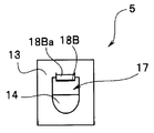
- FIG. 11 is a perspective view of the shield case 5 having an extending portion according to the second modification.
- FIG. 12 is a view of the shield case 5 having the extending portion according to the second modification viewed from the proximal direction.
- FIG. 13 is a cross-sectional view showing a state in which the vibrator unit 2 is housed in the housing portion 3 a of the housing 3.
- the same constituent elements as those in the above-described embodiment are given the same reference numerals, and the description thereof is omitted.
- the extension portion 18 ⁇ / b> B of the present modification is plate-shaped, but has a convex portion 18 ⁇ / b> Ba protruding to the upper surface side in part.
- a recessed portion 31 formed by being recessed is provided in a part of the inner peripheral surface of the cable insertion path 21.
- the convex portion 18 ⁇ / b> Ba fits into a concave portion 31 formed on the inner peripheral surface of the cable insertion passage 21 when the vibrator unit 2 is stored in the storage portion 3 a of the housing 3. It is provided in shape and position.
- the protruding amount of the convex portion 18Ba to the upper side must be an amount that allows the extending portion 18B and the cable 4a to be inserted into the cable insertion path 21.
- the extension portion 18B of this modification has a convex portion 18Ba, and has a concave portion 31 on the inner peripheral surface of the cable insertion passage 21, and the convex portion 18Ba and the concave portion 31 are fitted to position the vibrator unit 2. Is surely done. That is, when the vibrator unit 2 is housed in the housing 3 via the shield case 5, the concave portion 31 and the convex portion 18Ba are fitted.
- the extension portion 18B of the present modification produces the same effect as the extension portion 18 of the above-described embodiment, and can reliably perform positioning of the vibrator unit 2 in the axial direction. There is also an effect that variation in assembly between products can be reduced.
- the protruding portion 18Ba is provided on the extending portion 18B, and the concave portion 31 is provided on the inner peripheral surface of the cable insertion passage 21, but the concave portion is provided on the extending portion 18B, and the cable insertion passage 21 is provided. You may make it provide a convex part in the internal peripheral surface.
- FIG. 14 is a view for explaining an extending portion according to the third modification.
- FIG. 14 is a cross-sectional view showing a state in which the vibrator unit 2 is housed in the housing portion 3a of the housing 3 according to the third modification.
- the same components as those in the above-described embodiment are denoted by the same reference numerals and description thereof is omitted.
- the stepped portion 32 with which the tip of the extending portion 18 or 18A abuts is inserted into the cable. It is formed above the inner peripheral surface of the passage 21.
- the distal end portion of the extending portion 18 or 18A comes into contact with the step portion 32 formed on the inner peripheral surface of the cable insertion path 21, so that the positioning of the vibrator unit 2 is performed reliably.
- FIGS. 15, 16, and 17 are views for explaining the extending portion according to the fourth modification.
- FIG. 15 is a perspective view of the shield case 5 having an extending portion according to the fourth modification.
- FIG. 16 is a view of the shield case 5 having the extending portion according to the fourth modification as viewed from the proximal direction.
- FIG. 17 is a cross-sectional view showing a state in which the vibrator unit 2 is housed in the housing portion 3 a of the housing 3.
- the same constituent elements as those in the above-described embodiment are denoted by the same reference numerals and description thereof is omitted.
- the extending portion 18 ⁇ / b> C of the present modification is plate-shaped, but has a protruding portion 18 ⁇ / b> Ca formed on the upper surface side along the extending direction of the extending portion 18 ⁇ / b> C.
- a groove 33 is formed on the inner peripheral surface of the storage portion 3a of the housing 3 as a recess portion into which the protruding portion 18Ca is engaged or fitted.
- the width of the groove portion 33 in the circumferential direction of the housing portion 3a of the housing 3 has a size that allows the protruding portion 18Ca to be fitted.
- the protrusion 18 ⁇ / b> Ca is formed along the axial direction on the inner peripheral surface of the cable insertion passage 21 when the vibrator unit 2 is stored in the storage portion 3 a of the housing 3. It has a shape that engages with the groove 33.
- the extension portion 18C of the present modification produces the same effect as the extension portion 18 of the above-described embodiment, and the effect that the vibrator unit 2 can be reliably positioned around the axis. Have.
- the stepped portion 33a on the proximal end side of the groove portion 33 in which the distal end portion of the extending portion 18C (the proximal end portion of the protruding portion 18Ca in FIG. 17) is formed on the inner peripheral surface of the cable insertion path 21 is provided. Therefore, the positioning of the vibrator unit 2 in the axial direction is also reliably performed. Further, the protruding portion 18Ca can be provided on the upper side of the extending portions 18A and 18B of the second modification.
- the stress concentration on the connection portion between the transducer unit and the cable unit is reduced, and the signal of the cable is reduced. It is possible to provide an ultrasonic endoscope that can prevent damage to the wire, disconnection, and the like.
- the extension portion 18 or the like is a flat plate shape or a plate shape having a curved surface formed on the upper side of the lead-out port 17 of the shield case 5, but the extension portion of the present embodiment is This is different from the first embodiment in that it is a coil spring member.
- the same components as those in the first embodiment will be described with the same reference numerals, and description thereof will be omitted.
- FIG. 18, FIG. 19 and FIG. 20 are diagrams for explaining the extending portion according to the present embodiment.
- FIG. 18 is a perspective view of the shield case 5 having an extending portion according to the present embodiment.
- FIG. 19 is a cross-sectional view for explaining a process in which the vibrator unit 2 to which the cable unit 4 is connected is fitted into the housing 3 a of the housing 3.
- FIG. 20 is a cross-sectional view showing a state in which the vibrator unit 2 of the present embodiment is housed in the housing portion 3 a of the housing 3. 18 to 20, the same components as those in the first embodiment described above are denoted by the same reference numerals and description thereof is omitted.
- the extending portion is configured by a coil spring member 41 that is a cylindrical spring.
- the coil spring member 41 is a coil spring wound so that metal wires are in close contact with each other.
- One end of the coil spring member 41 is fixed to the lead-out port 17 formed on the side surface on the proximal end side of the shield case 5 by welding.
- the outlet 17 and the hollow portion inside the coil spring member 41 communicate with each other.
- the cable 4 a passes through the hollow portion inside the coil spring member 41.
- the coil spring member 41 described above is a single coil spring, but the spring member constituting the extending portion may be a multiple coil spring such as double or triple.
- the coil spring member 41 has elasticity, when the shield unit 5 is housed in the housing portion 3a, the coil spring member 41 faces the upper side of the opening 22 of the cable insertion path 21 of the housing 3. The coil spring member 41 enters the cable insertion passage 21 while the outer peripheral side of the coil spring member 41 abuts.
- the connection part between the cable unit 4 and the vibrator unit 2 is protected by the extending part 18, and the housing 3 of the vibrator unit 2 is housed.
- the bending stress applied to the connection portion between the cable unit 4 and the vibrator unit 2 is relieved when stored in the portion 3a.
- there also exists a merit that adjustment of the length of the axial direction of the coil spring member 41 which is an extension part is easy. Furthermore, if the axial length of the coil spring member 41 is increased, the shielding performance of the cable unit 4 with respect to the cable 4a can be further improved.
- the stress concentration on the connection portion between the transducer unit and the cable unit is alleviated, and the cable end is prevented from buckling. It is possible to provide an ultrasonic endoscope that can prevent the signal line from being damaged or disconnected. Furthermore, according to the present embodiment described above, the assemblability of the tip unit is improved, the yield is improved, and the cost is reduced.
- the coil spring member 41 as the extending portion relieves the bending stress in the lower side or the lateral direction, the bending stress in all directions during the work is relieved, and the cable signal line is damaged or disconnected. Etc. can be prevented.
- a convex portion as in Modification 2 of the first embodiment may be provided on the upper side of the coil spring member 41 of the present embodiment.
- a convex portion as in Modification 4 of the first embodiment may be provided on the upper side of the coil spring member 41 of the present embodiment.
- the distal end unit containing the ultrasonic transducer may be mounted in the distal rigid member of the ultrasonic endoscope together with the imaging unit including the imaging element.
- FIG. 21 is a partial cross-sectional view of the transducer unit mounted in the distal end hard member together with the imaging unit.
- FIG. 22 is a diagram viewed from the distal end side of the insertion portion of the ultrasonic endoscope.
- FIG. 21 is a sectional view taken along line XX-XX in FIG.
- the distal end portion 101 of the insertion portion of the ultrasonic endoscope includes a distal end rigid member 102 having a size of R1 in the radial direction.
- an imaging unit 103 incorporating an imaging element and an objective optical system and a vibrator unit 104 are provided on the distal end side in the insertion direction S of the insertion portion.
- the distal end in the insertion direction S of the vibrator unit 104 is forward of the distal end hard member 102 in the insertion direction S with respect to the distal end face 102 s of the distal hard member 102. Is provided so as to protrude.
- the distal end rigid member 102 is provided with a treatment instrument insertion channel and an illumination unit (both not shown), and an air / water supply pipe (not shown), a front water supply pipe (see FIG. 22), and the like. Is also provided.
- the distal end surface 102s is provided with an objective optical system 103a constituting the imaging unit 103 and an illumination optical system 105 constituting the illumination unit, and an opening of the treatment instrument insertion channel.
- the vibrator unit 104 includes a shield case 111 and a vibrator case 112 in which the shield case 111 is inserted.
- an ultrasonic transducer 113 In the shield case 111, an ultrasonic transducer 113, a wiring substrate 114, a flexible substrate 115, and the like are provided.
- the distal end portion of the cable 116 is connected to the flexible substrate 115 in the shield case 111, and the cable 116 extends from the proximal end side of the vibrator case 112.
- the tip of the vibrator unit 104 is reflected in the optical image because it is within the imaging range R ⁇ b> 2 of the imaging unit 103. That is, a part of the optical observation range has been vignetted. Since there are built-in objects such as the wiring board 114 in the vibrator unit 104, the above-mentioned vignetting may occur when the length of the vibrator unit 104 in the axial direction cannot be shortened.
- an opening is provided in a part in the base end direction of the shield case 111 so that the built-in object (here, the base end portion 114a of the substrate 114) does not hit the shield case 114.
- the axial length is shortened.
- FIG. 23 is a partial cross-sectional view of a vibrator unit in which an opening is provided in a part of the shield case 111.
- an opening 111a is provided on a part of the shield case 111 and on the base end side.
- the opening 111a is provided at a position where the base end portion 114a of the wiring board 114 hits the shield case 111 and interferes when the wiring board 114 is moved to the base end side.
- the opening 111a has a shape such that the wiring board 114 does not hit the shield case 111 when the wiring board 114 is moved to the proximal end side.
- the distal end portion of the vibrator unit 104 can be moved further to the proximal end side, the reflection of the vibrator unit 104 in the optical image can be prevented.
- the axial length of the distal end hard member can be shortened.
- FIG. 24 is a partial cross-sectional view of the imaging unit and the light guide unit along the line XXIV-XXIV in FIG.
- FIG. 24 shows an example in which a resin cover 121 has arrived at the distal end side of the distal end hard member 102.
- the imaging unit 122 and the light guide unit 123 are shown.
- the imaging unit 122 includes an objective optical system 122a and an imaging element 122b, and a cable 122d including a drive signal line and an imaging signal line is connected via a circuit board 122c.
- the imaging unit 122 includes a lens frame 124 that holds the objective optical system 122a and an imaging element frame 125 that includes the imaging element 122b.
- the lens frame 124 and the imaging element frame 125 are both cylindrical frame members made of stainless steel, and the outer peripheral portion on the proximal end side of the lens frame 124 is inserted into the inner peripheral portion on the distal end side of the imaging element frame 125. It is mated.
- Adhesive is applied to the outer peripheral surface on the base end side of the lens frame 124 and the inner peripheral surface on the front end side of the imaging element frame 125, and after the optical focal position is adjusted, the adhesive is solidified.
- the imaging unit 122 is produced.
- a fitting region 126 between the outer peripheral portion on the proximal end side of the lens frame 124 and the inner peripheral portion on the distal end side of the imaging element frame 125 is an adhesive surface.
- the light guide unit 123 includes an illumination optical system 123a and an optical fiber bundle 123b. After the light guide unit 123 is inserted from the distal end side of the distal end hard member 102 and the cover 121 is attached, an adhesive 131 is applied around the illumination window, and the light guide unit 123 is fixed.
- the imaging unit 122 is attached to the distal end hard member 102 from the proximal end side of the distal end hard member 102, and after the cover 121 is attached, the adhesive 132 around the observation window is applied and fixed.
- the endoscope is heated to a high temperature for cleaning and disinfection.
- each member, adhesive, and the like are thermally expanded, but the adhesive may peel off from the member because of a difference in expansion coefficient. Therefore, an outward flange portion 124 a protruding in the outer peripheral direction is provided at a slightly central portion in the axial direction of the lens frame 124. Since the outward flange portion 124a is thick in the radial direction, the outward flange portion 124a has high rigidity and has an effect of reducing deformation due to thermal expansion. That is, since the lens frame 124 has the outward flange portion 124a, the rigidity against deformation that causes the lens frame 124 to expand during thermal expansion is high.
- the peripheral portion on the front end side of the lens frame 124 is not covered with the cover 121 but is covered with the adhesive 132. Therefore, the periphery of the lens frame 124 is not covered with the cover 121 but is covered with the adhesive 132.
- the adhesive has been applied over a wide range around the tip lens 122a1 of the objective optical system 122a.
- the adhesive between the lens frame 124 and the tip lens 122a1 is used.
- the adhesive 133 is applied only to the gaps between them. For example, once the adhesive is applied as indicated by the alternate long and short dash line, the adhesive around the front end of the lens frame 124 is wiped off, so that only the gap between the lens frame 124 and the front lens 122a1 is removed. 133 can be applied.
- the outward flange portion 124a is provided on the lens frame 124, the periphery of the lens frame 124 is covered with the adhesive 132, and the gap between the lens frame 124 and the front lens 122a1 is covered with the adhesive 133. Intrusion of moisture into the lens frame 124 due to heat load caused by heating during cleaning and disinfection can be prevented.
- an endoscope may be used with a tube such as a water supply tube connected to the endoscope.
- FIG. 25 is an external view showing an external appearance of an ultrasonic endoscope to which a tube is attached.
- An ultrasonic endoscope 200 shown in FIG. 25 includes an elongated insertion part 210 to be inserted into a subject, an operation part 203 provided at the proximal end in the insertion direction S of the insertion part 210, and an operation part 203.
- the extended flexible cord 204 and the connector 205 provided at the extended end of the universal cord 204 constitute a main part.
- the connector 205 is provided with a light source connector 205a, an electrical connector 205b, an ultrasonic connector 205c, a suction base 205d, an air / water supply base 205e, and a sub-water supply base 205f.
- a light source device that supplies illumination light is detachable to the light source connector 205a, and a video processor that performs various signal processing and the like via a signal cable is detachable to the electrical connector 205b.
- the ultrasonic observation device can be attached to and detached from the ultrasonic connector 205c via an ultrasonic cable 206 connected to the ultrasonic observation device, and a suction pump can be attached to and removed from the suction base 205d via a suction tube.
- a water supply tank can be attached to and detached from the air / water supply base 205e via an air supply / water supply tube, and a water supply tank can be attached to and detached from the sub-water supply base 205f via a water supply tube 207. It has become.
- the insertion part 210 includes, in order from the distal end side in the insertion direction S, a distal end part 211, a bending part 212 configured to be able to bend in the vertical and horizontal directions, and a long and flexible flexible tube part. 213 are connected to each other.
- various tubes can be attached to the endoscope 200, here, the auxiliary water supply tube 207 will be described, and description of application to other tubes will be omitted.
- auxiliary water supply tube 207 is connected to the auxiliary water supply cap 205f, and the other end is connected to a water supply tank (not shown).
- the auxiliary water supply tube 207 is provided with mounting clips 201 at a plurality of locations on the way.
- FIG. 26 is a partial cross-sectional view of the mounting clip 201 along the line XXVI-XXVI in FIG.
- the mounting clip 201 is made of resin and includes a ring portion 222 and an arm portion 223.
- a tube such as the auxiliary water supply tube 207 is inserted through the hole 222 a at the center of the ring portion 222. Therefore, the opening diameter of the hole 222a is large enough to allow various tubes to be inserted.
- the arm portion 223 includes two arms 223 a and 223 b, and each arm extends from the ring portion 222.
- Each of the two arms 223a and 223b includes a first portion 223a1 and 223b1 extending from the ring portion 222, and a second portion 223a2 and 223b2 extending from the tip side of the first portion.
- the connecting portion of the second portion is curved.
- the first portions 223a1 and 223b1 extend straight, that is, substantially linearly, and the second portions 223a2 and 223b2 also have straight portions.
- An inner portion sandwiched between the two arms 223a and 223b constitutes a gripping portion.
- the arm part 223 is formed so that the gripping part forms a substantially rhombus indicated by a dotted line. Accordingly, the two arms 223a and 223b are longer than when the gripping portion is formed in a circular shape.
- a groove 224 is formed outside the two arms 223a and 223b.
- open leg portions 223a3 and 223b3 are provided on the distal ends of the two arms 223a and 223b so that a cord or the like can easily enter the grip portion.
- FIG. 27 is a cross-sectional view showing a state in which the attachment clip 201 is attached to the universal cord 204. If the universal cord 204 is pressed so as to be fitted into the gripping part in a state where the sub-water feeding tube 207 is inserted into the hole 222a of the ring part 222, the space between the distal ends of the two arms 223a and 223b is opened. The cord 204 is gripped by the arm portion 223 so as to fit into the grip portion.
- the gripping portion is rhombus and the arm portion 223, particularly the first portions 223a1 and 223b1, are formed relatively long, the amount of force required when the universal cord 204 is attached to the arm portion 223 is small. I'll do it.
- the contact between the universal cord 204 having a circular cross-sectional shape and the two arms 223a and 223b is a line contact. (Or point contact), the amount of force required to remove the attachment clip 201 from the universal cord 204 is small.
- a portion indicated by a dotted circle indicates a portion where the universal cord 204 and each arm are in line contact.
- connection part of the 1st part of the arm part 223, and the 2nd part so that the contact part with the two arms 223a and 223b may become a line contact with respect to all the types of the universal cords 204 to be mounted.
- the mounting clip 201 can be attached to and detached from the universal cord 204 with a small amount of force. Furthermore, the attachment clip 201 can be attached to various cords having different diameters.
- the surface state of the inner portion of the arm portion 223 of the mounting clip 201 may be intentionally roughened or finely uneven. By doing so, the frictional force between the universal cord 204 and the mounting clip 201 can be reduced, and the universal cord 204 can be prevented from being damaged.
- FIG. 28 is a view of the mounting clip 201 provided with an extension at the tip of the arm.
- the open leg portions 223a3 and 223b3 at the tip of the arm portion 223 of the mounting clip 201 may be extended to provide the C-shaped extension portions 223a4 and 223b4.
- the arm portion 223 is gently pushed and expanded by the C-shaped extensions 223a4 and 223b4 at the time of attachment to the universal cord 204. The amount of force required for mounting can be further reduced.
- the stress concentration at the connection portion between the transducer unit and the cable unit is reduced when the ultrasonic endoscope is assembled.
- buckling of the cable end can be prevented, and disconnection of the signal line of the cable can be prevented.
Abstract
超音波内視鏡は、上面と、底面と、上面及び底面を繋ぐ側面とを有し、上面側で超音波の送受信を行う振動子ユニット2と、振動子ユニット2と電気信号を送受信するための前記側面に接続されたケーブル4aと、ケーブル4aを導出するための導出口17と、導出口17のうち少なくとも上面側から延出された可撓性の延出部18とを有し、側面及び底面を覆う導電性のシールドケース5と、シールドケース5を介して振動子ユニット2を保持し、ケーブル4a及び延出部18を内部に挿通するケーブル挿通路21を有するハウジング3とを有する。
Description
本発明は、超音波内視鏡に関する。
従来より、医療分野において、超音波内視鏡装置が広く利用されている。超音波内視鏡では、超音波の送受信を行う超音波探触子が、細長の内視鏡挿入部の先端部に設けられている。超音波内視鏡装置は、その超音波探触子から超音波を送信し、被検体から受信した超音波エコー信号から被検体の超音波画像を生成して表示する。
超音波内視鏡の挿入部の先端部に設けられている超音波探触子内部には、振動部を有する振動子ユニットが配置されている。振動子ユニットは、ハウジング内に収納される。さらに、挿入部は、被検体内に挿入されるため、被検体に対する電気的な安全、ノイズ対策、等を考慮して、振動子ユニットは、接地されたシールドケース内に設けられている。
振動子ユニットを含む先端部ユニットを組み立てる場合、まず、細長いケーブルユニットが接続された振動子ユニットをシールドケースに収める。そして、細長いケーブルユニットが接続された振動子ユニットをハウジング内に押し込むようにして収納することによって、超音波内視鏡の先端部ユニットが組み立てられる。その結果、シールドケースに収められた振動子ユニットが、挿入部の先端部のハウジング内に収納される。
また、超音波内視鏡における超音波振動により発生した熱の対策として、例えば、日本特開2009-240755号公報には、先端部に高熱伝導層を設ける技術が提案され開示されている。
しかし、ハウジング内に振動子ユニットを組み付けるとき、ケーブルユニットが接続された状態で、振動子ユニットをハウジング内に嵌め込むようにして、その組み付けは行われる。具体的には、ケーブルユニットの基端側を、ハウジングのケーブル導出口からハウジングの外側へ引き出し、ケーブルユニットの先端部に接続された振動子ユニットを、ハウジングの収納部に嵌め込むようにして、振動子ユニットはハウジング内に収納される。
挿入部の先端部の小型化のために、ハウジングの収納部内のケーブルユニットの挿通路の開口部は小さく、かつ収納部の窪みも軸方向には大きくない。そのため、組み立て作業者が振動子ユニットをハウジングの収納部内に嵌め込むとき、振動子ユニットとケーブルユニットの接続部に曲げ応力が集中して、ケーブルユニット内の信号線がダメージを受け易く、ダメージが大きいと内部の信号線が断線する虞がある。
従来は、このような組み立て時の振動子ユニットとケーブルユニットの接続部に曲げ応力が集中してケーブルユニット内の信号線がダメージを受ける問題については、考慮されていなかった。
上述した高熱伝導層を有する超音波内視鏡の提案には、基端側に延出した高熱伝導層が開示されているが、その提案には、上記のような組み立て時の振動子ユニットとケーブルユニットの接続部に集中する曲げ応力に対する対策は、何ら考慮されていない。
そこで、本願発明は、超音波内視鏡の組み立て時に、振動子ユニットとケーブルユニットとの接続部への応力集中を緩和して、ケーブルの信号線の損傷、断線等を防止することができる超音波内視鏡を提供することを目的とする。
本発明の一態様の超音波内視鏡は、上面と底面と前記上面及び前記底面を繋ぐ側面とを有し、前記上面側で超音波の送受信を行う超音波送受信部と、前記超音波送受信部と電気信号を送受信するための前記側面に接続されたケーブルと、前記ケーブルを導出するための導出口と、前記導出口のうち少なくとも前記上面側から延出された可撓性の延出部とを有し、前記側面及び前記底面を覆う導電性のシールドケースと、前記シールドケースを介して前記超音波送受信部を保持し、前記ケーブル及び前記延出部を内部に挿通するケーブル挿通路を有するハウジングと、を有する。
以下、図面を参照して本発明の実施の形態を説明する。
なお、以下の説明に用いる各図においては、各構成要素を図面上で認識可能な程度の大きさとするため、各構成要素毎に縮尺を異ならせてあるものもあり、本発明は、これらの図に記載された構成要素の数量、構成要素の形状、構成要素の大きさの比率、及び各構成要素の相対的な位置関係のみに限定されるものではない。
なお、以下の説明に用いる各図においては、各構成要素を図面上で認識可能な程度の大きさとするため、各構成要素毎に縮尺を異ならせてあるものもあり、本発明は、これらの図に記載された構成要素の数量、構成要素の形状、構成要素の大きさの比率、及び各構成要素の相対的な位置関係のみに限定されるものではない。
(第1の実施の形態)
図1及び図2は、本発明の第1の実施の形態に係わる超音波内視鏡の先端部ユニットの外観図である。図1は、先端部ユニットの前方斜め上から見た斜視図であり、図2は、先端部ユニットの横やや斜め後ろから見た斜視図である。図3は、先端部ユニット1の軸方向の前方から見た図である。
図1及び図2は、本発明の第1の実施の形態に係わる超音波内視鏡の先端部ユニットの外観図である。図1は、先端部ユニットの前方斜め上から見た斜視図であり、図2は、先端部ユニットの横やや斜め後ろから見た斜視図である。図3は、先端部ユニット1の軸方向の前方から見た図である。
先端部ユニット1は、主に、振動子ユニット2と、ハウジング3と、ケーブルユニット4と、シールドケース5(図1、図2、図3では図示せず)とを有して構成されている。振動子ユニット2がハウジング3の収納部3a内に収納され、ハウジング3の基端側からケーブルユニット4のケーブル4aが延出するように、先端部ユニット1は構成されている。先端部ユニット1が超音波内視鏡の挿入部の先端硬質部材内に設けられて、内視鏡先端部は構成される。
超音波送受信部である振動子ユニット2は、内部に超音波トランスデューサを有する。振動子ユニット2の上面側には、超音波を集束させる音響レンズ面2aが設けられている。振動子ユニット2の下部は、後述するシールドケース5内に収納されている。
振動子ユニット2は、上面と、底面と、上面及び底面を繋ぐ側面とを有し、上面側で超音波の送受信を行う超音波送受信部を構成する。ここでは、上面に、音響レンズ面2aがある。
振動子ユニット2は、上面と、底面と、上面及び底面を繋ぐ側面とを有し、上面側で超音波の送受信を行う超音波送受信部を構成する。ここでは、上面に、音響レンズ面2aがある。
ハウジング3は、樹脂製であり、ハウジング本体部3bと、そのハウジング本体部3bの先端部に形成されたフランジ部を有する突出部3b1と、基端部3b2を有する。基端部3b2からは、ケーブル4aが延出している。ケーブル4aは、超音波送受信部である振動子ユニット2と電気信号を送受信するために、振動子ユニット2の側面に接続されている。
ハウジング本体部3bの収納部3aの開口部は、振動子ユニット2の音響レンズ面2aの形状に沿った形状を有する。ハウジング3の内部構造については、後述する。
なお、本実施の形態及び以下の説明(変形例及び他の実施の形態の説明)は、超音波送受信部がコンベックス型のもので説明するが、コンケイブ型のものでもよい。
なお、本実施の形態及び以下の説明(変形例及び他の実施の形態の説明)は、超音波送受信部がコンベックス型のもので説明するが、コンケイブ型のものでもよい。
図4は、シールドケース5の斜視図である。図5は、シールドケース5を基端方向から見た図である。シールドケース5は、開口部11と、底面部12と、4つの側面部13,14,15、16を有している。シールドケース5は、金属製であり、上面の開口部11の面積が、底面部12の面積よりも大きい、上側に開いた箱形形状を有している。よって、底面部12と、4つの側面部13,14,15,16とにより、収納部5aが形成されている。
より具体的には、基端側の側面部13、15,16は、底面部12に対して直交し、先端側の側面部14は、底面部12との成す角度が90度以上となるように、シールドケース5は、構成されている。
また、基端側の側面部13の底面部12からの高さは、先端側の側面部14の底面部12からの高さよりも高いため、開口部11は、底面部12に対して斜めに形成される。
また、基端側の側面部13の底面部12からの高さは、先端側の側面部14の底面部12からの高さよりも高いため、開口部11は、底面部12に対して斜めに形成される。
基端側の側面部13には、ケーブルユニット4のケーブル4aを、シールドケース5の外へ導き出すための導出口17が形成されている。図5に示すように、導出口17は、底面側が半円形で、上面側が矩形で、ケーブル4aが挿通可能な大きさを有する。
さらに、その開口部16の上側、すなわち導出口17の上面側、には、基端方向に延出する板状の延出部18が形成されている。延出部18は、振動子ユニット2がシールドケース5に収納されたときに、振動子ユニット1から延出するケーブル4aの上側表面が延出部18の下面に当接する位置に、形成されている。
すなわち、シールドケース5は、ケーブル4aを導出するための導出口17と、導出口17のうち少なくとも上面側から延出された可撓性の延出部18とを有し、振動子ユニット2の側面及び底面を覆う導電性の部材である。
シールドケース5は、一枚の金属製の板材を、折り曲げ、ろう付け等の加工などにより製造される。本実施の形態では、延出部18は、金属製で、可撓性を有し、シールドケース5及び延出部18は、折り曲げ加工により製造される。
例えば、延出部18の長さは、1~3mmで、厚さは、0.2mmである。なお、後述するように、延出部18は、弾性を有する材料が好ましい。弾性を有する金属として、例えば、銅、燐青銅がある。
なお、図4及び図5に示すように、シールドケース5の先端側の側面部14には、スルーホール14aが設けられており、そのスルーホール14aを介して、内部の接地用配線をシールドケース5の外部へ引き出し、接地用配線をシールドケース5の外側で半田付けすることができるように、シールドケース5は構成されている。
なお、接地用配線をシールドケース5の外側に引き出すために、円形のスルーホール14aに代えて、図6において点線で示すように、U字状の切り欠きを、先端側の側面部14に形成してもよい。
なお、接地用配線をシールドケース5の外側に引き出すために、円形のスルーホール14aに代えて、図6において点線で示すように、U字状の切り欠きを、先端側の側面部14に形成してもよい。
このようなスルーホール14aを設けることにより、シールドケース5の外側で半田付けなどの配線ができるので、作業性がよい。また、シールドケース5の先端側に配線箇所がくるため、超音波内視鏡の先端部の小型化になる。
さらに、振動子ユニット2内の導体板(図示せず)とシールドケース5の側面部を同一平面上に配置することにより、両者を隙間なく配置でき、配線部分を完全に金属部材で覆うことができるので、確実な接地が可能となる。
さらにまた、配線部分が振動子ユニット2の音響レンズ面2aよりも先端側に突出しているため、振動子ユニット2内の絶縁部材が破壊されても、いわゆる患者回路にも電流が流れない。
図6は、振動子ユニット2のシールドケース5への収納を説明するための図である。本実施の形態の振動子ユニット2は、超音波振動子、音響レンズなどを含む上部2Aと、回路基板などを含む下部2Bとからなる。上部2Aは、下部2Bよりも大きく、下部2Bは、シールドケース5の収納部5aの形状に対応した形状を有する。
振動子ユニット2をシールドケース5へ収納する場合、まず、ケーブルユニット4のケーブル4aの基端部を、導出口17にシールドケース5の内側から挿通し、ケーブル4aの先端部まで、ケーブル4aを導出口17に通す。そして、ケーブル4aの先端部を導出口17の内側に押し当てるようにして、振動子ユニット2の下部2Bを、シールドケース5内に収納する。このようにして、振動子ユニット2の下部2Bは、シールドケース5の収納部5a内に収納される。
図7は、ケーブルユニット4が接続された振動子ユニット2が、ハウジング3の収納部3a内への嵌め込まれる過程を説明するための断面図である。
まず、図7により、ハウジング3の内部の構造について説明する。略円柱形状を有するハウジング3のハウジング本体部3bには、収納部3aが形成されている。収納部3aは、ハウジング本体部3bに形成された凹部であり、振動子ユニット2を収納可能な大きさを有する。基端部3b2には、収納部3aと連通するケーブル挿通路21が設けられている。収納部3aの基端側には、ケーブル挿通路21の開口部22が形成されている。開口部22には、ケーブル4aの挿入性向上のためのテーパー部22aが形成されている。
まず、図7により、ハウジング3の内部の構造について説明する。略円柱形状を有するハウジング3のハウジング本体部3bには、収納部3aが形成されている。収納部3aは、ハウジング本体部3bに形成された凹部であり、振動子ユニット2を収納可能な大きさを有する。基端部3b2には、収納部3aと連通するケーブル挿通路21が設けられている。収納部3aの基端側には、ケーブル挿通路21の開口部22が形成されている。開口部22には、ケーブル4aの挿入性向上のためのテーパー部22aが形成されている。
よって、ハウジング3は、シールドケース5を介して振動子ユニット2を保持し、かつケーブル4a及び延出部18を内部に挿通するケーブル挿通路21を有する。
このハウジング3の収納部3a内へ振動子ユニット2を嵌め込む場合、まず、ケーブル4aの基端部を開口部22からケーブル挿通路21に通して、ケーブル4aを引き出し、ケーブル4aの先端部、すなわちケーブルユニット4と振動子ユニット2の接続部を、開口部22に近付ける。そして、図7のように、シールドケース5の延出部18の先端部を、収納部3aの開口部22からケーブル挿通路21内に挿入する。
このとき、図7に示すように、延出部18が開口部22の端部の上側に当接しかつ滑りながら、延出部18の基端部は、収納部3aの開口部22からケーブル挿通路21内に挿入される。さらに、延出部18は弾性を有する場合は、延出部18のバネ性により、延出部18がケーブル挿通路21内に自然に引き込まれていくように、作業者は、延出部18をケーブル挿通路21内に挿入することができる。また、テーパー部22aが開口部22に形成されているので、さらに、収納し易くなっている。
さらに、振動子ユニット2のハウジング3の収納部3a内への収納過程において、ケーブルユニット4と振動子ユニット2の接続部は、延出部18によって保護され、振動子ユニット2のハウジング3の収納部3a内への収納時にかかる、ケーブルユニット4と振動子ユニット2の接続部への曲げ応力が緩和される。
すなわち、図7に示すように、振動子ユニット2が基端部3b2のケーブル挿通路21の軸に対して斜め方向から嵌め込まれるが、振動子ユニット2とケーブルユニット4の接続部に集中する曲げ応力は延出部18により緩和されるので、ケーブルユニット4内の信号線へのダメージは、受け難い。その結果、内部の信号線の断線も発生し難い。図8は、振動子ユニット2がハウジング3の収納部3aに収納された状態を示す断面図である。
よって、上述した構成によれば、超音波内視鏡の組み立て時に、振動子ユニットとケーブルユニットの接続部への応力集中を緩和し、ケーブル端の座屈を防止して、ケーブルの信号線の損傷、断線等を防止することができる。さらに、上述した本実施の形態によれば、先端部ユニットの組み立て性が向上して、歩留まりも向上し、ひいては、コストの低減にも繋がる。
なお、収納部3aの開口部22からケーブル挿通路21内に沿って、板状の延出部18が入り込む溝を設け、その溝の幅(ケーブル挿通路21の軸方向に直交する方向の幅)を、延出部18の幅と略同じにし、その溝に延出部18を挿入するようにすることによって、振動子ユニット2の軸回りにおける位置決めを確実に行うようにすることもできる。すなわち、開口部16の上面側に設けられる溝の幅を、延出部18が入り込み可能で軸回りに回動しないようなサイズにすることによって、収納部3a内に収納される振動子ユニット2の軸回りの位置決めが可能となる。
なお、延出部18は、各種変形例の構成を取り得、次のような構成を有するものであってもよい。
(変形例1)
図9と図10は、本変形例1に係る延出部を説明するための図である。図9は、変形例1にかかる延出部を有するシールドケース5の斜視図である。図10は、シールドケース5を基端方向から見た図である。図9と図10において、上述した実施の形態と同じ構成要素については、同じ符号を付し説明は省略する。
(変形例1)
図9と図10は、本変形例1に係る延出部を説明するための図である。図9は、変形例1にかかる延出部を有するシールドケース5の斜視図である。図10は、シールドケース5を基端方向から見た図である。図9と図10において、上述した実施の形態と同じ構成要素については、同じ符号を付し説明は省略する。
図9に示すように、本変形例の延出部18Aは、導出口17の上面側に配置され、上面側に突出した曲面形状を有する。より具体的には、延出部18Aは、図10に示すように、導出口17の形状の一部に沿った、樋形状を有する。
本変形例の延出部18Aは上側に突出した曲面形状を有するため、曲げ応力が振動子ユニット2とケーブルユニット4との接続部にかかったときに、延出部18Aは、図4に示すような延出部18よりも、反作用として生じる力が大きい。
よって、本変形例の延出部18Aは、上述した実施の形態の延出部18と同様の効果を生じさせると共に、延出部18Aの厚さを薄くできるという効果もある。
(変形例2)
図11,図12及び図13は、本変形例2に係る延出部を説明するための図である。図11は、本変形例2に係る延出部を有するシールドケース5の斜視図である。図12は、本変形例2に係る延出部を有するシールドケース5を基端方向から見た図である。図13は、振動子ユニット2がハウジング3の収納部3aに収納された状態を示す断面図である。図11から図13において、上述した実施の形態と同じ構成要素については、同じ符号を付し説明は省略する。
図11,図12及び図13は、本変形例2に係る延出部を説明するための図である。図11は、本変形例2に係る延出部を有するシールドケース5の斜視図である。図12は、本変形例2に係る延出部を有するシールドケース5を基端方向から見た図である。図13は、振動子ユニット2がハウジング3の収納部3aに収納された状態を示す断面図である。図11から図13において、上述した実施の形態と同じ構成要素については、同じ符号を付し説明は省略する。
図11に示すように、本変形例の延出部18Bは、板状であるが、一部に、上面側に突出した凸部18Baを有する。ケーブル挿通路21の内周面の一部には、凹ませて形成された凹部31が設けられている。図13に示すように、その凸部18Baは、振動子ユニット2がハウジング3の収納部3a内に収納されたときに、ケーブル挿通路21の内周面に形成された凹部31に嵌合する形状及び位置に、設けられている。
よって、凸部18Baの上側への突出量は、延出部18Bとケーブル4aが、ケーブル挿通路21内に挿通可能な量でなければならない。
本変形例の延出部18Bは凸部18Baを有し、ケーブル挿通路21の内周面に凹部31を有して、凸部18Baと凹部31が嵌合して、振動子ユニット2の位置決めが確実に行われる。すなわち、シールドケース5を介して、振動子ユニット2がハウジング3に収納されたときに、凹部31と凸部18Baとが嵌合する。
よって、本変形例の延出部18Bは、上述した実施の形態の延出部18と同様の効果を生じさせると共に、振動子ユニット2の軸方向における位置決めを確実に行うことができ、ひいては、製品間の組み付けのバラツキを少なくすることができるという効果もある。
なお、本変形例では、延出部18Bに凸部18Baが設けられ、ケーブル挿通路21の内周面に凹部31が設けられているが、延出部18Bに凹部を設け、ケーブル挿通路21の内周面に凸部を設けるようにしてもよい。
(変形例3)
図14は、本変形例3に係る延出部を説明するための図である。図14は、本変形例3に係る、振動子ユニット2がハウジング3の収納部3aに収納された状態を示す断面図である。図14において、上述した実施の形態と同じ構成要素については、同じ符号を付し説明は省略する。
図14は、本変形例3に係る延出部を説明するための図である。図14は、本変形例3に係る、振動子ユニット2がハウジング3の収納部3aに収納された状態を示す断面図である。図14において、上述した実施の形態と同じ構成要素については、同じ符号を付し説明は省略する。
図14に示すように、本変形例では、振動子ユニット2がハウジング3の収納部3a内に収納されたときに、延出部18あるいは18Aの先端部が当接する段差部32が、ケーブル挿通路21の内周面の上側に形成されている。
本変形例では、延出部18あるいは18Aの先端部がケーブル挿通路21の内周面に形成された段差部32に当接して、振動子ユニット2の位置決めが確実に行われる。
よって、本変形例の構成においても、上述した実施の形態の延出部18と同様の効果を生じさせると共に、振動子ユニット2の軸方向における位置決めを確実に行うことができるという効果もある。
(変形例4)
図15,図16及び図17は、本変形例4に係る延出部を説明するための図である。図15は、本変形例4に係る延出部を有するシールドケース5の斜視図である。図16は、本変形例4に係る延出部を有するシールドケース5を基端方向から見た図である。図17は、振動子ユニット2がハウジング3の収納部3aに収納された状態を示す断面図である。図15から図17において、上述した実施の形態と同じ構成要素については、同じ符号を付し説明は省略する。
図15,図16及び図17は、本変形例4に係る延出部を説明するための図である。図15は、本変形例4に係る延出部を有するシールドケース5の斜視図である。図16は、本変形例4に係る延出部を有するシールドケース5を基端方向から見た図である。図17は、振動子ユニット2がハウジング3の収納部3aに収納された状態を示す断面図である。図15から図17において、上述した実施の形態と同じ構成要素については、同じ符号を付し説明は省略する。
図15に示すように、本変形例の延出部18Cは、板状であるが、延出部18Cの延出方向に沿って上面側に形成された突出部18Caを有する。ハウジング3の収納部3aの内周面には、突出部18Caが係合あるいは嵌合する窪み部である溝33が形成されている。ハウジング3の収納部3aの周方向における溝部33の幅は、突出部18Caが嵌合するサイズを有する。
すなわち、図17に示すように、その突出部18Caは、振動子ユニット2がハウジング3の収納部3a内に収納されたときに、ケーブル挿通路21の内周面に軸方向に沿って形成された溝部33に係合する形状を有する。
よって、本変形例の延出部18Cは、上述した実施の形態の延出部18と同様の効果を生じさせると共に、振動子ユニット2の軸回りにおける位置決めを確実に行うことができるという効果を有する。
なお、本変形例では、延出部18Cの先端部(図17では、突出部18Caの基端部)がケーブル挿通路21の内周面に形成された溝部33の基端側の段差部33aに当接するようになっているので、振動子ユニット2の軸方向における位置決めも確実に行われる。
さらに、突出部18Caは、変形例2の延出部18A、18Bの上側に設けることも可能である。
さらに、突出部18Caは、変形例2の延出部18A、18Bの上側に設けることも可能である。
以上のように、上述した本実施の形態及び各変形例によれば、超音波内視鏡の組み立て時に、振動子ユニットとケーブルユニットとの接続部への応力集中を緩和して、ケーブルの信号線の損傷、断線等を防止することができる超音波内視鏡を提供することができる。
(第2の実施の形態)
第1の実施の形態において延出部18等は、シールドケース5の導出口17の上側に形成された平らな板状あるいは曲面を有する板状であるが、本実施の形態の延出部は、コイルバネ部材である点で、第1の実施の形態と異なる。なお、本実施の形態において、第1の実施の形態と同じ構成要素については、同じ符号を付して説明し、説明は省略する。
第1の実施の形態において延出部18等は、シールドケース5の導出口17の上側に形成された平らな板状あるいは曲面を有する板状であるが、本実施の形態の延出部は、コイルバネ部材である点で、第1の実施の形態と異なる。なお、本実施の形態において、第1の実施の形態と同じ構成要素については、同じ符号を付して説明し、説明は省略する。
図18、図19及び図20は、本実施の形態に係る延出部を説明するための図である。図18は、本実施の形態に係る延出部を有するシールドケース5の斜視図である。図19は、ケーブルユニット4が接続された振動子ユニット2が、ハウジング3の収納部3a内への嵌め込まれる過程を説明するための断面図である。図20は、本実施の形態の振動子ユニット2がハウジング3の収納部3aに収納された状態を示す断面図である。図18から図20において、上述した第1の実施の形態と同じ構成要素については、同じ符号を付し説明は省略する。
本実施の形態では、延出部は、筒状のバネであるコイルバネ部材41から構成されている。図18に示すように、コイルバネ部材41は、金属線が互いに密着するように巻かれたコイルバネである。コイルバネ部材41の一端が、シールドケース5の基端側の側面に形成された導出口17に、溶接により固着される。導出口17と、コイルバネ部材41の内側の中空部が連通する。振動子ユニット2をシールドケース5内に収納したとき、コイルバネ部材41の内側の中空部内を、ケーブル4aが通っている。
なお、上述したコイルバネ部材41は一重のコイルバネであるが、延出部を構成するバネ部材は、2重、3重などの多重のコイルバネでもよい。
なお、上述したコイルバネ部材41は一重のコイルバネであるが、延出部を構成するバネ部材は、2重、3重などの多重のコイルバネでもよい。
図19に示すように、コイルバネ部材41は、弾性を有するため、シールドユニット5を収納部3a内に収納するとき、ハウジング3のケーブル挿通路21の開口部22の上側に対して、コイルバネ部材41の外周側が当接しながら、コイルバネ部材41はケーブル挿通路21内に入り込む。
よって、振動子ユニット2のハウジング3の収納部3a内への収納過程において、ケーブルユニット4と振動子ユニット2の接続部は、延出部18によって保護され、振動子ユニット2のハウジング3の収納部3a内への収納時に、ケーブルユニット4と振動子ユニット2の接続部への曲げ応力が緩和される。
また、本実施の形態では、延出部であるコイルバネ部材41の軸方向の長さの調整がし易いというメリットもある。さらにまた、コイルバネ部材41の軸方向の長さが長くなれば、ケーブルユニット4のケーブル4aに対するシールド性を、より向上させることができる。
また、本実施の形態では、延出部であるコイルバネ部材41の軸方向の長さの調整がし易いというメリットもある。さらにまた、コイルバネ部材41の軸方向の長さが長くなれば、ケーブルユニット4のケーブル4aに対するシールド性を、より向上させることができる。
従って、上述した本実施の形態によれば、超音波内視鏡の組み立て時に、振動子ユニットとケーブルユニットとの接続部への応力集中を緩和し、ケーブル端の座屈を防止して、ケーブルの信号線の損傷、断線等を防止することができる超音波内視鏡を提供することができる。さらに、上述した本実施の形態によれば、先端部ユニットの組み立て性が向上して、歩留まりも向上し、ひいては、コストの低減にも繋がる。
また、延出部としてのコイルバネ部材41は、下側あるいは横方向への曲げ応力に対しても緩和するので、作業中におけるあらゆる方向における曲げ応力を緩和して、ケーブルの信号線の損傷、断線等を防止することができる。
なお、振動子ユニットの位置決めのために、本実施の形態のコイルバネ部材41の上側に、第1の実施の形態の変形例2のような凸部を設けてもよい。
さらになお、振動子ユニットの軸回りの位置決めのために、本実施の形態のコイルバネ部材41の上側に、第1の実施の形態の変形例4のような凸部を設けてもよい。
さらになお、振動子ユニットの軸回りの位置決めのために、本実施の形態のコイルバネ部材41の上側に、第1の実施の形態の変形例4のような凸部を設けてもよい。
(振動子ユニットの短小化)
ところで、超音波トランスデューサを内蔵する先端部ユニットが、撮像素子を含む撮像ユニットと共に、超音波内視鏡の先端硬質部材内に装着される場合がある。図21は、撮像ユニットと共に先端硬質部材内に装着された振動子ユニットの部分断面図である。図22は、超音波内視鏡の挿入部の先端側から見た図である。図21は、図22のXX-XX線に沿った断面図である。
ところで、超音波トランスデューサを内蔵する先端部ユニットが、撮像素子を含む撮像ユニットと共に、超音波内視鏡の先端硬質部材内に装着される場合がある。図21は、撮像ユニットと共に先端硬質部材内に装着された振動子ユニットの部分断面図である。図22は、超音波内視鏡の挿入部の先端側から見た図である。図21は、図22のXX-XX線に沿った断面図である。
図21に示すように、超音波内視鏡の挿入部の先端部101は、その径方向にR1の大きさを有する先端硬質部材102を具備する。
先端硬質部材101内には、挿入部の挿入方向Sの先端側に、撮像素子や対物光学系を内蔵する撮像ユニット103と、振動子ユニット104が、設けられている。
先端硬質部材101内には、挿入部の挿入方向Sの先端側に、撮像素子や対物光学系を内蔵する撮像ユニット103と、振動子ユニット104が、設けられている。
また、図21に示すように、振動子ユニット104は、先端硬質部材102に対して、振動子ユニット104の挿入方向Sの先端が、先端硬質部材102の先端面102sよりも挿入方向Sの前方に突出するよう設けられている。
また、先端硬質部材102内には、処置具挿通チャンネルや、照明ユニット(いずれも図示されず)が設けられている他、図示しない送気送水管路や前方送水管路(図22参照)等も設けられている。
また、図22に示すように、先端面102sには、撮像ユニット103を構成する対物光学系103aや、照明ユニットを構成する照明光学系105が設けられているとともに、処置具挿通用チャンネルの開口106、前方送水管路の開口107、さらに、対物光学系103aに流体を供給する送気送水管路の先端に固定された送気送水ノズル108等が設けられている。
振動子ユニット104は、シールドケース111と、シールドケース111を内挿する振動子ケース112とを有して構成されている。シールドケース111内には、超音波トランスデューサ113、配線基板114,フレキシブル基板115などが設けられている。ケーブル116の先端部がシールドケース111内のフレキシブル基板115に接続され、ケーブル116は、振動子ケース112の基端側から延出している。
図21の場合、振動子ユニット104の先端部が、撮像ユニット103の撮像範囲R2内に入っているため、光学画像に映り込んでいる。すなわち、光学観察範囲の一部がケラレてしまっている。振動子ユニット104内には、配線基板114などの内蔵物があるため、振動子ユニット104の軸方向の長さを短くできない場合、上記のようなケラレが生じてしまうことがある。
そこで、ここでは、シールドケース111の基端方向の一部に開口部を設け、内蔵物(ここでは基板114の基端部114a)がシールドケース114に当たらないようにして、振動子ユニット104の軸方向の長さを短くしている。
図23は、シールドケース111の一部に開口部を設けた振動子ユニットの部分断面図である。図23に示すように、シールドケース111の一部でかつ基端側に、開口部111aが設けられている。
開口部111aは、配線基板114を基端側に移動させたときに、配線基板114の基端部114aがシールドケース111に当たって干渉する位置に設けられる。
また、開口部111aは、配線基板114を基端側に移動させたときに、配線基板114がシールドケース111に当たらないような形状を有する。
開口部111aは、配線基板114を基端側に移動させたときに、配線基板114の基端部114aがシールドケース111に当たって干渉する位置に設けられる。
また、開口部111aは、配線基板114を基端側に移動させたときに、配線基板114がシールドケース111に当たらないような形状を有する。
よって、振動子ユニット104の先端部を、より基端側に移動できるので、光学画像への振動子ユニット104の映り込みを防止することができる。また、先端硬質部材の軸方向の長さも短くすることができる。
(レンズの曇り防止)
また、図24は、図22のXXIV-XXIV線に沿った、撮像ユニットとライトガイドユニットの部分の部分断面図である。なお、図24は、先端硬質部材102の先端側に、樹脂製のカバー121が到着されている例である。図24では、撮像ユニット122とライトガイドユニット123が示されている。
また、図24は、図22のXXIV-XXIV線に沿った、撮像ユニットとライトガイドユニットの部分の部分断面図である。なお、図24は、先端硬質部材102の先端側に、樹脂製のカバー121が到着されている例である。図24では、撮像ユニット122とライトガイドユニット123が示されている。
撮像ユニット122は、対物光学系122aと撮像素子122bを含み、回路基板122cを介して、駆動信号線及び撮像信号線を含むケーブル122dが接続されている。
撮像ユニット122は、対物光学系122aを保持するレンズ枠124と、撮像素子122bを含む撮像素子枠125とを含む。レンズ枠124と撮像素子枠125は、共にステンレス製の筒状の枠部材であって、レンズ枠124の基端側の外周部が、撮像素子枠125の先端側の内周部に挿入されて嵌合している。レンズ枠124の基端側の外周面と撮像素子枠125の先端側の内周面には接着剤が塗布されて、光学的な焦点位置の調整がされた後に、接着剤を固化させて、撮像ユニット122が作製される。図24において、レンズ枠124の基端側の外周部と、撮像素子枠125の先端側の内周部との嵌合領域126が、接着面となる。
ライトガイドユニット123は、照明光学系123aと、光ファイバ束123bとを含む。ライトガイドユニット123は、先端硬質部材102の先端側から挿入されて、カバー121が取り付けられた後に、照明窓の周囲に接着剤131が塗布されて、ライトガイドユニット123は固定される。
撮像ユニット122は、先端硬質部材102の基端側から、先端硬質部材102に装着され、カバー121が取り付けられた後に、観察窓の周囲の接着剤132が塗布されて固定される。
内視鏡は洗浄消毒のために高温に加熱される。加熱されると、各部材、接着剤等が熱膨張するが、その膨張率に差があるため、接着剤が部材から剥がれてしまう場合がある。
そこで、レンズ枠124の軸方向のやや中央部に、外周方向に突出した外向フランジ部124aが設けられている。外向フランジ部124aは、径方向に厚いので、剛性が高く、熱膨張による変形を少なくする作用を有する。すなわち、レンズ枠124は、外向フランジ部124aを有するので、熱膨張時においてレンズ枠124が広がるような変形に対する剛性が高くなっている。
そこで、レンズ枠124の軸方向のやや中央部に、外周方向に突出した外向フランジ部124aが設けられている。外向フランジ部124aは、径方向に厚いので、剛性が高く、熱膨張による変形を少なくする作用を有する。すなわち、レンズ枠124は、外向フランジ部124aを有するので、熱膨張時においてレンズ枠124が広がるような変形に対する剛性が高くなっている。
また、レンズ枠124の先端側の周囲部分はカバー121によって覆われずに、接着剤132により覆っている。よって、レンズ枠124の周囲は、カバー121によって覆われずに、接着剤132によって覆われている。
さらに、従来は、一点鎖線で示すように、対物光学系122aの先端レンズ122a1の周りの広い範囲に亘って接着剤が塗布されていたのを、ここでは、レンズ枠124と先端レンズ122a1との間の隙間部分だけに接着剤133を塗布するようにしている。例えば、一旦、一点鎖線で示すように接着剤を塗布した後、レンズ枠124の先端部の周囲の接着剤を拭き取ることによって、レンズ枠124と先端レンズ122a1との間の隙間部分だけに接着剤133を塗布することができる。
従来は、一点鎖線で示す広い範囲に接着剤が塗布されていたので、加熱による熱膨張により、レンズ枠124を広げるような応力が発生していたため、レンズ枠124と先端レンズ122a1との間に隙間が発生し、その隙間から内部に水分が入り込み、対物光学系122aにおいて、所謂曇りが発生することがあった。
しかし、上記のように、レンズ枠124に外向フランジ部124aを設け、レンズ枠124の周囲を接着剤132で覆い、かつレンズ枠124と先端レンズ122a1の間を接着剤133で覆うようにしたので、洗浄消毒時における加熱による熱負荷による、レンズ枠124内への水分の浸入を防止することができる。
(取付ケーブル)
また、超音波内視鏡に限らず、一般に、内視鏡は、送水チューブ等のチューブが内視鏡に接続されて使用される場合がある。図25は、チューブが取り付けられている超音波内視鏡の外観を示す外観図である。
また、超音波内視鏡に限らず、一般に、内視鏡は、送水チューブ等のチューブが内視鏡に接続されて使用される場合がある。図25は、チューブが取り付けられている超音波内視鏡の外観を示す外観図である。
図25に示す超音波内視鏡200は、被検体内に挿入される細長な挿入部210と、この挿入部210の挿入方向Sの基端に設けられた操作部203と、操作部203から延出された可撓性を有するユニバーサルコード204と、該ユニバーサルコード204の延出端に設けられたコネクタ205とにより主要部が構成されている。
コネクタ205に、光源コネクタ205aと、電気コネクタ205bと、超音波コネクタ205cと、吸引口金205dと、送気送水口金205eと、副送水口金205fが設けられている。
光源コネクタ205aに、照明光を供給する光源装置が着脱自在になっているとともに、電気コネクタ205bに、信号ケーブルを介して各種の信号処理等を行うビデオプロセッサが着脱自在となっている。
また、超音波コネクタ205cに、超音波観測装置に接続される超音波ケーブル206を介して超音波観測装置が着脱自在となっているともに、吸引口金205dに、吸引チューブを介して吸引ポンプが着脱自在であり、さらに、送気送水口金205eに、送気・送水チューブを介して送水タンクが着脱自在となっており、副送水口金205fに、送水チューブ207を介して送水タンクが着脱自在となっている。
挿入部210は、挿入方向Sの先端側から順に、先端部211と、例えば上下方向及び左右方向に湾曲自在に構成された湾曲部212と、長尺でかつ可撓性を有する可撓管部213とが連設されて構成されている。
内視鏡200には、各種チューブが取り付け可能となっているが、ここでは、副送水チューブ207について説明し、他のチューブへの適用についての説明は省略する。
内視鏡200には、各種チューブが取り付け可能となっているが、ここでは、副送水チューブ207について説明し、他のチューブへの適用についての説明は省略する。
副送水チューブ207の一端は、副送水口金205fに接続され、他端は、送水タンク(図示せず)に接続される。副送水チューブ207には、途中に複数箇所に取付用クリップ201が設けられている。
図26は、図25のXXVI-XXVI線に沿った、取付用クリップ201の部分断面図である。取付用クリップ201は、樹脂製であり、リング部222と、アーム部223とからなる。リング部222の中央の孔部222aには、副送水チューブ207等のチューブが挿通される。よって、孔部222aの開口径は、各種チューブを挿通できる大きさを有する。
アーム部223は、2本のアーム223a、223bを含み、各アームは、リング部222から延出している。2本のアーム223a、223bは、それぞれ、リング部222から伸びる第1の部分223a1、223b1と、第1の部分の先端側から伸びる第2の部分223a2、223b2とからなり、第1の部分と第2の部分の接続部分は、湾曲している。
図26に示すように、第1の部分223a1,223b1は、真っ直ぐに、すなわち略直線状に、伸びており、第2の部分223a2,223b2も、真っ直ぐに伸びた部分を有しており、2つのアーム223a、223bに挟まれる内側部分が、把持部を構成する。把持部が点線で示す略菱形を成すように、アーム部223は形成されている。従って、2つのアーム223a、223bは、把持部を円形に形成した場合と比べて、長い。
なお、2つのアーム223a、223bの外側には、溝224が形成されている。
さらに、2つのアーム223a、223bの先端側には、コードなどが把持部内に入り込み易いように、開脚部223a3,223b3が設けられている。
なお、2つのアーム223a、223bの外側には、溝224が形成されている。
さらに、2つのアーム223a、223bの先端側には、コードなどが把持部内に入り込み易いように、開脚部223a3,223b3が設けられている。
図27は、取付用クリップ201がユニバーサルコード204に取り付けられた状態を示す断面図である。
リング部222の孔部222aに副送水チューブ207が挿通されている状態で、ユニバーサルコード204を、把持部に嵌め込むようにして押し付けると、2つのアーム223a、223bの先端部の間が開きながら、ユニバーサルコード204が、把持部に嵌り込むようにして、アーム部223により把持される。
リング部222の孔部222aに副送水チューブ207が挿通されている状態で、ユニバーサルコード204を、把持部に嵌め込むようにして押し付けると、2つのアーム223a、223bの先端部の間が開きながら、ユニバーサルコード204が、把持部に嵌り込むようにして、アーム部223により把持される。
このとき、把持部が菱形で、アーム部223,特に第1の部分223a1、223b1、が比較的長く形成されているので、アーム部223にユニバーサルコード204を装着するときに必要な力量は、小さくて済む。
さらに、図27に示すように、アーム部223の把持部によってユンバーサルコード204が把持されているとき、断面形状が円形のユニバーサルコード204と、2つのアーム223a、223bとの接触は、線接触(あるいは点接触)となるため、取付用クリップ201をユニバーサルコード204から取り外すときの力量も小さくて済むことになる。図27において、点線の円形で示した部分が、ユニバーサルコード204と、各アームが線接触する部分を示す。
なお、装着されるユニバーサルコード204の全ての種類に対して、2つのアーム223a、223bとの接触部分が線接触になるように、アーム部223の第1の部分と第2の部分の接続部分を湾曲させることによって、取付用クリップ201が取り付けられる全てのコードからの、取付用クリップの取り外し力量を小さくすることができる。
以上のような取付用クリップ201によれば、ユニバーサルコード204に対する取付用クリップ201の取り付け及び取り外しが、小さな力量で可能となる。さらに、径の異なる種々のコードにも、取付用クリップ201は取付可能である。
なお、上述した例は、副送水チューブ207に取り付けた取付用クリップを、ユニバーサルコード204に取り付ける例を説明したが、他のチューブ、あるいは他の取付対象コードについても同様に適用可能である。
ユニバーサルコード204と取付用クリップ201を密着させないために、取付用クリップ201のアーム部223内側部分の表面状態を、意図的に粗くしたり細かい凹凸をつけたりしてもよい。こうすることでユニバーサルコード204と取付用クリップ201間の摩擦力を軽減させることができ、ユニバーサルコード204に傷が付くことを防ぐことができる。
図28は、アーム部先端に延長部を設けた取付用クリップ201の図である。図28に示すように、取付用クリップ201のアーム部223先端の開脚部223a3及び223b3を延長して、ハの字の延長部223a4及び223b4を設けてもよい。このような形状にすることでユニバーサルコード204への取り付け時には、ハの字状の延長部223a4及び223b4によってアーム部223が緩やかに押し広げられるようになり、取付用クリップ201の、ユニバーサルコード204に装着するときに必要な力量をさらに小さくすることができる。
上述した各実施の形態及びその各変形例によれば、超音波内視鏡の組み立て時に、振動子ユニットとケーブルユニットとの接続部への応力集中、すなわちケーブル端への応力集中、を緩和して、ケーブル端の座屈を防止して、ケーブルの信号線の断線を防止することができる。
本発明は、上述した実施の形態に限定されるものではなく、本発明の要旨を変えない範囲において、種々の変更、改変等が可能である。
本出願は、2011年9月9日に日本国に出願された特願2011-197506号を優先権主張の基礎として出願するものであり、上記の開示内容は、本願明細書、請求の範囲に引用されるものとする。
Claims (12)
- 上面と底面と前記上面及び前記底面を繋ぐ側面とを有し、前記上面側で超音波の送受信を行う超音波送受信部と、
前記超音波送受信部と電気信号を送受信するための前記側面に接続されたケーブルと、
前記ケーブルを導出するための導出口と、前記導出口のうち少なくとも前記上面側から延出された可撓性の延出部とを有し、前記側面及び前記底面を覆う導電性のシールドケースと、
前記シールドケースを介して前記超音波送受信部を保持し、前記ケーブル及び前記延出部を内部に挿通するケーブル挿通路を有するハウジングと、
を有することを特徴とする超音波内視鏡。 - 前記延出部は、前記導出口の上面側に配置された板形状あるいは曲面形状を有することを特徴とする請求項1に記載の超音波内視鏡。
- 前記延出部は、筒状のバネにより構成されることを特徴とする請求項1に記載の超音波内視鏡。
- 前記ケーブル挿通路には、前記ケーブル挿通路の内周面の一部を凹ませて形成された凹部が設けられ、
前記延出部には、前記延出部の一部を前記上面側に突出した凸部が設けられ、
前記シールドケースを介して、前記超音波送受信部が前記ハウジングに収納されたときに、前記凹部と前記凸部とが嵌合することを特徴とする請求項1から3のいずれか1つに記載の超音波内視鏡。 - 前記ケーブル挿通路には、前記ケーブル挿通路の内周面の一部を前記内周面側に突出した凸部が設けられ、
前記延出部には、前記延出部の一部を凹ませて形成された凹部が設けられ、
前記シールドケースを介して、前記超音波送受信部が前記ハウジングに収納されたときに、前記凸部と前記凹部とが嵌合することを特徴とする請求項1にから3のいずれか1つに記載の超音波内視鏡。 - 前記延出部には、前記延出部の延出方向に沿って形成された突出部が設けられ、
前記ハウジングには、前記突出部が嵌合する窪み部が設けられていることを特徴とする請求項1又は2に記載の超音波内視鏡。 - 前記ハウジングの前記ケーブル挿通路には、前記延出部が当接する段差部が設けられていることを特徴とする請求項1又は2に記載の超音波内視鏡。
- 前記ハウジングの前記ケーブル挿通路には、前記延出部が入り込む溝が設けられていることを特徴とする請求項1又は2に記載の超音波内視鏡。
- 前記ハウジングの前記ケーブル挿通路の開口部には、テーパー部が形成されていることを特徴とする請求項1又は2に記載の超音波内視鏡。
- 前記ハウジングの先端側側面部には、スルーホール又は切り欠きが設けられていることを特徴とする請求項1から3のいずれか1つに記載の超音波内視鏡。
- 前記延出部は、弾性を有することを特徴とする請求項1から3のいずれか1つに記載の超音波内視鏡。
- 前記筒状のバネは、コイルバネであることを特徴とする請求項3に記載の超音波内視鏡。
Priority Applications (4)
| Application Number | Priority Date | Filing Date | Title |
|---|---|---|---|
| JP2013506380A JP5253691B1 (ja) | 2011-09-09 | 2012-04-19 | 超音波内視鏡 |
| EP12829864.3A EP2641542B9 (en) | 2011-09-09 | 2012-04-19 | Ultrasonic endoscope |
| CN201280004263.9A CN103269645B (zh) | 2011-09-09 | 2012-04-19 | 超声波内窥镜 |
| US13/764,881 US8696583B2 (en) | 2011-09-09 | 2013-02-12 | Ultrasound endoscope |
Applications Claiming Priority (2)
| Application Number | Priority Date | Filing Date | Title |
|---|---|---|---|
| JP2011197506 | 2011-09-09 | ||
| JP2011-197506 | 2011-09-09 |
Related Child Applications (1)
| Application Number | Title | Priority Date | Filing Date |
|---|---|---|---|
| US13/764,881 Continuation US8696583B2 (en) | 2011-09-09 | 2013-02-12 | Ultrasound endoscope |
Publications (1)
| Publication Number | Publication Date |
|---|---|
| WO2013035374A1 true WO2013035374A1 (ja) | 2013-03-14 |
Family
ID=47831839
Family Applications (1)
| Application Number | Title | Priority Date | Filing Date |
|---|---|---|---|
| PCT/JP2012/060558 WO2013035374A1 (ja) | 2011-09-09 | 2012-04-19 | 超音波内視鏡 |
Country Status (5)
| Country | Link |
|---|---|
| US (1) | US8696583B2 (ja) |
| EP (1) | EP2641542B9 (ja) |
| JP (1) | JP5253691B1 (ja) |
| CN (1) | CN103269645B (ja) |
| WO (1) | WO2013035374A1 (ja) |
Cited By (3)
| Publication number | Priority date | Publication date | Assignee | Title |
|---|---|---|---|---|
| WO2014192599A1 (ja) * | 2013-05-31 | 2014-12-04 | オリンパスメディカルシステムズ株式会社 | 内視鏡 |
| US9517052B2 (en) | 2014-01-06 | 2016-12-13 | Olympus Corporation | Ultrasound endoscope |
| WO2019146331A1 (ja) * | 2018-01-29 | 2019-08-01 | 富士フイルム株式会社 | 超音波内視鏡及び超音波内視鏡の製造方法 |
Families Citing this family (17)
| Publication number | Priority date | Publication date | Assignee | Title |
|---|---|---|---|---|
| US8574160B2 (en) | 2008-12-18 | 2013-11-05 | C. R. Bard, Inc. | Needle guides for a sonographic imaging device |
| US10863970B2 (en) | 2008-12-18 | 2020-12-15 | C. R. Bard, Inc. | Needle guide including enhanced visibility entrance |
| EP2654568A1 (en) | 2010-12-22 | 2013-10-30 | C. R. Bard, Inc. | Selectable angle needle guide |
| CN103619263B (zh) | 2011-06-23 | 2017-02-15 | C·R·巴德股份有限公司 | 具有可选方面的针导引件 |
| DE102014214754A1 (de) | 2014-07-28 | 2016-01-28 | Digital Endoscopy Gmbh | Endoskopische Vorrichtung |
| CN106456132B (zh) * | 2014-08-18 | 2019-09-20 | 奥林巴斯株式会社 | 超声波内窥镜、超声波观察装置及超声波内窥镜系统 |
| EP3165170A4 (en) * | 2014-12-01 | 2018-05-23 | Olympus Corporation | Ultrasonic endoscope |
| DE102015113020B4 (de) * | 2015-08-07 | 2023-10-05 | Digital Endoscopy Gmbh | Endoskopkopf |
| EP3344401B1 (en) * | 2015-09-03 | 2022-04-06 | Koninklijke Philips N.V. | Ic die, probe and ultrasound system |
| JP6663997B2 (ja) * | 2016-08-04 | 2020-03-13 | オリンパス株式会社 | 超音波振動子モジュールの製造方法および超音波内視鏡 |
| US11399800B2 (en) * | 2016-12-20 | 2022-08-02 | New York Society For The Relief Of The Ruptured And Crippled, Maintaining The Hospital For Special Surgery | Constant force ultrasound probe handle |
| JP6672200B2 (ja) * | 2017-02-23 | 2020-03-25 | 富士フイルム株式会社 | 内視鏡 |
| CN109199453A (zh) * | 2017-06-30 | 2019-01-15 | 深圳开立生物医疗科技股份有限公司 | 一种超声内镜连接件和一种超声内镜 |
| WO2019241833A1 (en) | 2018-06-20 | 2019-12-26 | Saban Ventures Pty Limited | Clamp for a medical device |
| DE102018128306A1 (de) * | 2018-11-13 | 2020-05-14 | Olympus Winter & Ibe Gmbh | Videoendoskop und Bremselement |
| CN114449956A (zh) * | 2019-09-26 | 2022-05-06 | 皇家飞利浦有限公司 | 多分段腔内成像设备和相关的设备、系统和方法 |
| DE102020117363A1 (de) * | 2020-07-01 | 2022-01-05 | Karl Storz Se & Co. Kg | HF-Abschirmbox, medizinisches Instrument und Verfahren |
Citations (4)
| Publication number | Priority date | Publication date | Assignee | Title |
|---|---|---|---|---|
| JP2002306490A (ja) * | 2001-04-18 | 2002-10-22 | Asahi Optical Co Ltd | 超音波内視鏡 |
| JP2004209044A (ja) * | 2003-01-06 | 2004-07-29 | Olympus Corp | 超音波内視鏡 |
| JP2009082360A (ja) * | 2007-09-28 | 2009-04-23 | Fujifilm Corp | 超音波探触子 |
| JP2009240755A (ja) * | 2008-03-13 | 2009-10-22 | Fujifilm Corp | 超音波内視鏡 |
Family Cites Families (27)
| Publication number | Priority date | Publication date | Assignee | Title |
|---|---|---|---|---|
| US5176140A (en) * | 1989-08-14 | 1993-01-05 | Olympus Optical Co., Ltd. | Ultrasonic probe |
| NL9001755A (nl) * | 1990-08-02 | 1992-03-02 | Optische Ind De Oude Delft Nv | Endoscopische aftastinrichting. |
| US5353798A (en) * | 1991-03-13 | 1994-10-11 | Scimed Life Systems, Incorporated | Intravascular imaging apparatus and methods for use and manufacture |
| JPH06292669A (ja) * | 1991-04-17 | 1994-10-21 | Hewlett Packard Co <Hp> | 超音波プローブ |
| JPH0734803B2 (ja) * | 1991-12-27 | 1995-04-19 | 松下電器産業株式会社 | 超音波探触子 |
| US5373849A (en) * | 1993-01-19 | 1994-12-20 | Cardiovascular Imaging Systems, Inc. | Forward viewing imaging catheter |
| US5402793A (en) * | 1993-11-19 | 1995-04-04 | Advanced Technology Laboratories, Inc. | Ultrasonic transesophageal probe for the imaging and diagnosis of multiple scan planes |
| JPH08280098A (ja) * | 1995-04-07 | 1996-10-22 | Olympus Optical Co Ltd | 超音波探触子用圧電素子 |
| JP3409655B2 (ja) * | 1997-07-24 | 2003-05-26 | 富士写真光機株式会社 | 経内視鏡的に挿入される超音波診断装置 |
| JP3525700B2 (ja) * | 1997-09-24 | 2004-05-10 | 富士写真光機株式会社 | 超音波プローブ |
| US7520856B2 (en) * | 1999-09-17 | 2009-04-21 | University Of Washington | Image guided high intensity focused ultrasound device for therapy in obstetrics and gynecology |
| JP2004512856A (ja) * | 1999-12-23 | 2004-04-30 | シーラス、コーポレイション | 画像形成および治療用超音波トランスデューサ |
| US6425870B1 (en) * | 2000-07-11 | 2002-07-30 | Vermon | Method and apparatus for a motorized multi-plane transducer tip |
| US6776758B2 (en) * | 2002-10-11 | 2004-08-17 | Koninklijke Philips Electronics N.V. | RFI-protected ultrasound probe |
| JP4283022B2 (ja) * | 2003-03-31 | 2009-06-24 | 東芝医用システムエンジニアリング株式会社 | 体腔内用超音波プローブ |
| JP3905494B2 (ja) * | 2003-05-28 | 2007-04-18 | オリンパス株式会社 | 超音波振動子 |
| JP4395603B2 (ja) * | 2004-03-31 | 2010-01-13 | 富士フイルム株式会社 | 超音波内視鏡 |
| JP4517239B2 (ja) * | 2005-03-04 | 2010-08-04 | 富士フイルム株式会社 | 超音波プローブ |
| US20060264831A1 (en) * | 2005-05-20 | 2006-11-23 | Medtronic, Inc. | Portable therapy delivery device with fluid delivery |
| US7798971B2 (en) * | 2005-07-07 | 2010-09-21 | Vermon | Motorized ultrasonic scanhead |
| JP5154144B2 (ja) * | 2007-05-31 | 2013-02-27 | 富士フイルム株式会社 | 超音波内視鏡及び超音波内視鏡装置 |
| JP5154146B2 (ja) * | 2007-06-05 | 2013-02-27 | 富士フイルム株式会社 | 超音波内視鏡及び超音波内視鏡装置 |
| JP5171191B2 (ja) * | 2007-09-28 | 2013-03-27 | 富士フイルム株式会社 | 超音波探触子 |
| JP5489418B2 (ja) * | 2008-05-08 | 2014-05-14 | オリンパスメディカルシステムズ株式会社 | 超音波プローブ用フード及び超音波プローブ |
| JP5308716B2 (ja) * | 2008-05-21 | 2013-10-09 | オリンパスメディカルシステムズ株式会社 | 電子内視鏡装置 |
| KR102352609B1 (ko) * | 2008-06-06 | 2022-01-18 | 얼테라, 인크 | 초음파 치료 시스템 |
| JP4547468B2 (ja) * | 2008-10-14 | 2010-09-22 | オリンパスメディカルシステムズ株式会社 | 超音波プローブ |
-
2012
- 2012-04-19 EP EP12829864.3A patent/EP2641542B9/en not_active Not-in-force
- 2012-04-19 CN CN201280004263.9A patent/CN103269645B/zh active Active
- 2012-04-19 WO PCT/JP2012/060558 patent/WO2013035374A1/ja active Application Filing
- 2012-04-19 JP JP2013506380A patent/JP5253691B1/ja active Active
-
2013
- 2013-02-12 US US13/764,881 patent/US8696583B2/en active Active
Patent Citations (4)
| Publication number | Priority date | Publication date | Assignee | Title |
|---|---|---|---|---|
| JP2002306490A (ja) * | 2001-04-18 | 2002-10-22 | Asahi Optical Co Ltd | 超音波内視鏡 |
| JP2004209044A (ja) * | 2003-01-06 | 2004-07-29 | Olympus Corp | 超音波内視鏡 |
| JP2009082360A (ja) * | 2007-09-28 | 2009-04-23 | Fujifilm Corp | 超音波探触子 |
| JP2009240755A (ja) * | 2008-03-13 | 2009-10-22 | Fujifilm Corp | 超音波内視鏡 |
Non-Patent Citations (1)
| Title |
|---|
| See also references of EP2641542A4 * |
Cited By (9)
| Publication number | Priority date | Publication date | Assignee | Title |
|---|---|---|---|---|
| WO2014192599A1 (ja) * | 2013-05-31 | 2014-12-04 | オリンパスメディカルシステムズ株式会社 | 内視鏡 |
| JP5830633B2 (ja) * | 2013-05-31 | 2015-12-09 | オリンパス株式会社 | 内視鏡 |
| CN105263421A (zh) * | 2013-05-31 | 2016-01-20 | 奥林巴斯株式会社 | 内窥镜 |
| EP2989991A4 (en) * | 2013-05-31 | 2016-12-28 | Olympus Corp | Borescope |
| CN105263421B (zh) * | 2013-05-31 | 2017-08-22 | 奥林巴斯株式会社 | 内窥镜 |
| US9782149B2 (en) | 2013-05-31 | 2017-10-10 | Olympus Corporation | Endoscope |
| US9517052B2 (en) | 2014-01-06 | 2016-12-13 | Olympus Corporation | Ultrasound endoscope |
| WO2019146331A1 (ja) * | 2018-01-29 | 2019-08-01 | 富士フイルム株式会社 | 超音波内視鏡及び超音波内視鏡の製造方法 |
| JPWO2019146331A1 (ja) * | 2018-01-29 | 2020-12-03 | 富士フイルム株式会社 | 超音波内視鏡及び超音波内視鏡の製造方法 |
Also Published As
| Publication number | Publication date |
|---|---|
| EP2641542A1 (en) | 2013-09-25 |
| EP2641542B1 (en) | 2014-06-11 |
| US8696583B2 (en) | 2014-04-15 |
| EP2641542B9 (en) | 2014-09-10 |
| JPWO2013035374A1 (ja) | 2015-03-23 |
| EP2641542A4 (en) | 2013-11-13 |
| US20130158410A1 (en) | 2013-06-20 |
| JP5253691B1 (ja) | 2013-07-31 |
| CN103269645B (zh) | 2015-06-03 |
| CN103269645A (zh) | 2013-08-28 |
Similar Documents
| Publication | Publication Date | Title |
|---|---|---|
| JP5253691B1 (ja) | 超音波内視鏡 | |
| US9050052B2 (en) | Ultrasound endoscope | |
| US10158188B2 (en) | Cable connection structure, ultrasonic probe, and ultrasonic endoscope system | |
| US8801255B2 (en) | Endoscope | |
| EP2740411A1 (en) | Ultrasonic endoscope | |
| EP2163184B1 (en) | Endoscope insertion portion | |
| EP2591731B1 (en) | Ultrasound transducer unit, ultrasound endoscope | |
| JP2009153902A (ja) | 電子内視鏡 | |
| CN106886088B (zh) | 内窥镜 | |
| US20130137990A1 (en) | Ultrasound endoscope | |
| US20180042463A1 (en) | Endoscope connector | |
| JP4468691B2 (ja) | 超音波信号ケーブルコネクタ装置 | |
| JP2008253451A (ja) | 内視鏡の先端部構造 | |
| JP5175639B2 (ja) | 内視鏡およびその組立方法 | |
| JP2011200401A (ja) | 内視鏡 | |
| JP5366722B2 (ja) | 内視鏡 | |
| JP2013179981A (ja) | 電子内視鏡装置 | |
| JP2011200338A (ja) | 電子内視鏡 | |
| JP4647968B2 (ja) | 超音波内視鏡 | |
| JP3722633B2 (ja) | 内視鏡 | |
| JP2019122671A (ja) | 超音波内視鏡及び内視鏡装置 | |
| JP3181937U (ja) | 超音波内視鏡の超音波コネクタ | |
| JP2016163769A (ja) | ケーブル接続構造、超音波探触子および超音波内視鏡システム | |
| JP2006158481A (ja) | 超音波内視鏡 | |
| JP2009089925A (ja) | 内視鏡 |
Legal Events
| Date | Code | Title | Description |
|---|---|---|---|
| ENP | Entry into the national phase |
Ref document number: 2013506380 Country of ref document: JP Kind code of ref document: A |
|
| 121 | Ep: the epo has been informed by wipo that ep was designated in this application |
Ref document number: 12829864 Country of ref document: EP Kind code of ref document: A1 |
|
| WWE | Wipo information: entry into national phase |
Ref document number: 2012829864 Country of ref document: EP |
|
| NENP | Non-entry into the national phase |
Ref country code: DE |