US9050052B2 - Ultrasound endoscope - Google Patents
Ultrasound endoscope Download PDFInfo
- Publication number
- US9050052B2 US9050052B2 US13/965,414 US201313965414A US9050052B2 US 9050052 B2 US9050052 B2 US 9050052B2 US 201313965414 A US201313965414 A US 201313965414A US 9050052 B2 US9050052 B2 US 9050052B2
- Authority
- US
- United States
- Prior art keywords
- circuit pattern
- drive wiring
- ultrasound
- main circuit
- flexible
- Prior art date
- Legal status (The legal status is an assumption and is not a legal conclusion. Google has not performed a legal analysis and makes no representation as to the accuracy of the status listed.)
- Active
Links
Images


Classifications
-
- A—HUMAN NECESSITIES
- A61—MEDICAL OR VETERINARY SCIENCE; HYGIENE
- A61B—DIAGNOSIS; SURGERY; IDENTIFICATION
- A61B8/00—Diagnosis using ultrasonic, sonic or infrasonic waves
- A61B8/44—Constructional features of the ultrasonic, sonic or infrasonic diagnostic device
- A61B8/4444—Constructional features of the ultrasonic, sonic or infrasonic diagnostic device related to the probe
-
- A—HUMAN NECESSITIES
- A61—MEDICAL OR VETERINARY SCIENCE; HYGIENE
- A61B—DIAGNOSIS; SURGERY; IDENTIFICATION
- A61B8/00—Diagnosis using ultrasonic, sonic or infrasonic waves
- A61B8/12—Diagnosis using ultrasonic, sonic or infrasonic waves in body cavities or body tracts, e.g. by using catheters
-
- A—HUMAN NECESSITIES
- A61—MEDICAL OR VETERINARY SCIENCE; HYGIENE
- A61B—DIAGNOSIS; SURGERY; IDENTIFICATION
- A61B8/00—Diagnosis using ultrasonic, sonic or infrasonic waves
- A61B8/44—Constructional features of the ultrasonic, sonic or infrasonic diagnostic device
- A61B8/4444—Constructional features of the ultrasonic, sonic or infrasonic diagnostic device related to the probe
- A61B8/445—Details of catheter construction
Definitions
- the present invention relates to an ultrasound endoscope with a transducer unit housed in a housing provided in a distal end portion of an insertion portion.
- ultrasound endoscopes including an ultrasound probe at a distal end of an elongated insertion portion of an endoscope have widely been used.
- Each such ultrasound endoscope forms an ultrasound endoscope system jointly with, for example, an ultrasound observation apparatus and a monitor.
- the ultrasound endoscope system transmits ultrasound from an ultrasound probe to a subject and processes a received ultrasound echo signal in the ultrasound observation apparatus, enabling provision of an ultrasound tomographic image of an inside of the subject.
- the ultrasound probe used in each such ultrasound endoscope includes, for example, a transducer unit resulting from unitization of a plurality of ultrasound transducers together with an acoustic matching layer and a back-side damping layer, and the transducer unit is housed in a housing portion formed in a housing, whereby a main part of the ultrasound probe is formed.
- a wiring board electrically connected to the respective ultrasound transducers is provided, and a plurality of drive wirings separately extending from the cable unit so as to correspond to the respective ultrasound transducers are electrically connected to respective terminals on the wiring board, respectively.
- a tubular wiring insertion portion (pipe portion) is provided so as to connect to the housing portion of the transducer unit formed in the housing (see, for example, Japanese Patent Application Laid-Open Publication No. 2004-209044).
- An ultrasound endoscope includes: an ultrasound transmitting/receiving section that transmits/receives ultrasound; at least one wiring board electrically connected to a back side of the ultrasound transmitting/receiving section; a plurality of drive wirings electrically connected to the wiring board; and a housing that houses the wiring board and holds the ultrasound transmitting/receiving section, wherein the housing includes a housing portion that houses the wiring board, and a tubular wiring insertion portion having a diameter smaller than the housing portion, the wiring insertion portion connecting to the housing portion; and wherein the wiring board includes a stiff portion electrically connected to the back side of the ultrasound transmitting/receiving section, a wrapping portion extending out from the stiff portion, the wrapping portion wrapping and bundling the plurality of the drive wirings and being inserted into the wiring insertion portion, and a protection sheet that extends out from the stiff portion and covers a portion of connection with the plurality of drive wirings.
- FIG. 1 is a diagram of a schematic configuration of an ultrasound endoscope
- FIG. 2 is a diagram of an end face of a distal end rigid portion
- FIG. 3 is a cross-sectional view along line III-III in FIG. 2 ;
- FIG. 4 is a cross-sectional view along line IV-IV in FIG. 3 ;
- FIG. 5 is an exploded side view illustrating a transducer unit to which a cable unit is connected, and a housing;
- FIG. 6 is an exploded perspective view illustrating a wiring board and a cable unit
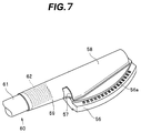
- FIG. 7 is a perspective view of a wiring board to which a cable unit is connected
- FIG. 8 is an exploded perspective view illustrating a modification of the wiring board and the cable unit
- FIG. 9 is a perspective view illustrating a modification of a flexible sheet
- FIG. 10 is a cross-sectional view of a main part of an observation optical lens system
- FIG. 11 is a cross-sectional view along line XI-XI in FIG. 10 ;
- FIG. 12 is a cross-sectional view of a main part, which illustrates a modification of the observation optical lens system
- FIG. 13 is a cross-sectional view along line XIII-XIII in FIG. 12 ;
- FIG. 14 is a cross-sectional view of a main part, which illustrates a modification of the observation optical lens system.
- FIG. 15 is a cross-sectional view along XV-XV in line FIG. 14 .
- FIG. 1 is a diagram of a schematic configuration of an ultrasound endoscope
- FIG. 2 is a diagram of an end face of a distal end rigid portion
- FIG. 3 is a cross-sectional view along line III-III in FIG. 2
- FIG. 4 is a cross-sectional view along line IV-IV in FIG. 3
- FIG. 5 is an exploded side view illustrating a transducer unit to which a cable unit is connected, and a housing
- FIG. 6 is an exploded perspective view illustrating a wiring board and a cable unit
- FIG. 7 is a perspective view of a wiring board to which a cable unit is connected
- FIG. 8 is an exploded perspective view illustrating a modification of the wiring board and the cable unit
- FIG. 9 is a perspective view illustrating a modification of a flexible sheet.
- An ultrasound endoscope system 1 which is illustrated in FIG. 1 , includes an ultrasound endoscope 2 , an ultrasound observation apparatus 3 and a monitor 4 . Also, the ultrasound endoscope 2 includes an elongated insertion portion 10 to be inserted into a body, an operation section 20 provided so as to be continuous with a proximal end of the insertion portion 10 , and a universal cord 30 extending from a side portion of the operation section 20 .
- a connector 31 connected to a light source apparatus is provided at a proximal end portion of the universal cord 30 .
- a cable 32 connected to a camera control unit (not illustrated) via a connector 32 a and a cable 33 detachably connected to the ultrasound observation apparatus 3 via a connector 33 a extend out from the connector 31 .
- the ultrasound observation apparatus 3 is connected to the ultrasound endoscope 2 via the connector 33 a and the monitor 4 is connected to the ultrasound endoscope 2 via the ultrasound observation apparatus 3 .
- the insertion portion 10 includes a main part including a distal end rigid portion 11 , a bending portion 12 positioned at a rear end of the distal end rigid portion 11 , and a flexible tube portion 13 positioned at a rear end of the bending portion 12 and extending to the operation section 20 , the tube portion 13 having a small diameter, a long length and flexibility, which are continuously provided in this order from the distal end side.
- an ultrasound probe 15 is disposed on the distal end side of the distal end rigid portion 11 . Furthermore, in a slant surface formed at a part of the distal end rigid portion 11 on the proximal side relative to the ultrasound probe 15 , an illumination lens 16 included in an illumination optical system, an observation lens 17 for an observation lens optical system, a forceps port 18 that doubles as a suction port and a non-illustrated air/water feeding nozzle are disposed.
- an angle knob 21 for performing bending control to bend the bending portion 12 in a desired direction an air/water feeding button 22 for performing air feeding and water feeding operations, a suction button 23 for performing an suction operation, and a treatment instrument insertion port 24 , which is an entrance for a treatment instrument to be introduced into a body, are disposed.
- the treatment instrument insertion port 24 connects to the forceps port 18 via a treatment instrument insertion channel (not illustrated) provided inside the insertion portion 10 .
- the ultrasound probe 15 in the present embodiment is a convex-type ultrasound probe, and the ultrasound probe 15 includes, for example, a transducer unit 50 that transmits/receives ultrasound, a cable unit 60 electrically connected to the transducer unit 50 , and a housing 70 that holds the transducer unit 50 .
- the transducer unit 50 includes an ultrasound transmitting/receiving section 51 including a plurality of elongated ultrasound transducer elements 51 a arranged in a substantially arc-like shape as a result of respective long sides of the ultrasound transducer elements 51 a being jointed to one another.
- the ultrasound transmitting/receiving section 51 is housed in a protection cover 52 in which a substantially arc-like acoustic lens layer 52 a is provided in an integrated manner.
- the respective ultrasound transducer elements 51 a are arranged so as to face an inner face of the acoustic lens layer 52 a and are bonded to the inner face of the acoustic lens layer 52 a via an acoustic matching layer 53 a.
- an end portion of a wiring board 55 is made to face the back side of the respective ultrasound transducer elements 51 a .
- electrode portions 56 a which correspond to the respective ultrasound transducer elements 51 a , are provided, and the ultrasound transducer elements 51 a are electrically and mechanically connected to the electrode portions 56 a via wires 54 .
- wires 54 e.g., soldering is preferably used for the connection of the wires 54 .
- a back-side damping layer (backing layer) 53 b is formed, and the respective wires 54 are sealed by the back-side damping layer 53 b.
- the wiring board 55 includes a rigid circuit board 56 , which is a stiff portion, and a pair of flexible circuit boards 57 attached to opposite faces of the rigid circuit board 56 , respectively.
- a wiring pattern including the aforementioned respective electrode portions 56 a and a plurality of pad electrodes 56 b electrically connected to the respective electrode portions 56 a are formed.
- each flexible circuit board 57 On one surface (inner side) of each flexible circuit board 57 that faces the rigid circuit board 56 , a plurality of inner electrode portions 57 a , which correspond to the pad electrodes 56 b are arranged, and on the other surface (outer) side, a wring pattern in which a plurality of outer electrode portions 57 b electrically connected to the respective inner electrode portions 57 a , respectively, are arranged is formed. Furthermore, a protection sheet 58 extends out from each of the flexible circuit boards 57 , the protection sheet 58 having a shape substantially symmetrical to the flexible circuit board 57 . Furthermore, a strip-shaped wrapping portion 59 extends out from one of the flexible circuit boards 57 .
- the protection sheet 58 and the wrapping portion 59 include, for example, a sheet material having flexibility and an insulating property, and are formed integrally with the flexible circuit board 57 .
- the inner sides of the respective flexible circuit boards 57 are bonded to the respective faces of the rigid circuit board 56 .
- the bonding of the flexible circuit boards 57 are performed by, for example, bonding the flexible circuit boards 57 to the rigid circuit board 56 via thermal compression bonding or soldering with the respective inner electrode portions 57 a on the flexible circuit board 57 positioned relative to the respective pad electrodes 56 b on the rigid circuit board 56 .
- the respective inner electrode portions 57 a on each of the flexible circuit boards 57 are electrically connected to the respective pad electrode 56 b on the rigid circuit board 56 .
- an adhesive used for the thermal compression bonding between the rigid circuit board 56 and the flexible circuit board 57 be a crosslinkable adhesive.
- the cable unit 60 includes, for example, a wiring group resulting from a plurality of drive wirings 62 , which each include a small-diameter coaxial cable, being integrally bundled by an outer coat 61 .
- the respective drive wirings 62 extend out branchingly from the outer coat 61 .
- Distal end portions of the respective separated drive wirings 62 are electrically connected to the respective outer electrode portions 57 b , respectively, on the outer sides of the respective flexible circuit board 57 .
- the respective drive wirings 62 are electrically connected to the respective ultrasound transducer elements 51 a .
- the drive wirings 62 e.g., soldering is preferably used for the connection of the drive wirings 62 .
- the protection sheets 58 extending out from the respective flexible circuit boards 57 are folded back so as to cover the respective outer electrode portions 57 b , and distal end portions of the protection sheets 58 are bonded to the rigid circuit board 56 via, for example, an adhesive 58 a (see FIG. 4 ). Consequently, portions of connection between the respective outer electrode portions 57 b and the respective drive wirings 62 are mechanically protected and electrically shielded.
- the wrapping portion 59 extending out from one of the flexible circuit boards 57 is wound around peripheral portions of the respective drive wirings 62 exposed from the outer coat 61 , and, for example, a distal end portion of the wrapping portion 59 is bonded to a part at a certain position of the wrapping portion 59 via an adhesive 59 a . Consequently, the respective drive wirings 62 exposed from the outer coat 61 are integrally bundled by the wrapping portion 59 (see FIGS. 5 and 7 ), and the respective drive wirings 62 are mechanically protected and electrically shielded.
- the housing 70 includes, for example, a member having a substantially U-shape in cross-section in which the housing portion 71 for the transducer unit 50 is provided in a recessed manner.
- a tubular wiring insertion portion 72 having a function as a connector for connection with the distal end rigid portion 11 is provided, and the inside of the wiring insertion portion 72 connects to the inside of the housing portion 71 .
- the transducer unit 50 is assembled to such housing 70 , for example, as illustrated in FIG. 5 , first, the proximal end side of the cable unit 60 is inserted into and through the wiring insertion portion 72 from the housing portion 71 side. Subsequently, the insertion work of pushing the respective drive wirings 62 integrally bundled by the wrapping portion 59 into the wiring insertion portion 72 and the work of housing the transducer unit 50 in the housing portion 71 are performed. Note that after the transducer unit 50 is housed in the housing portion 71 , and inside the housing portion 71 , for example, a resin adhesive 73 is charged through the wiring insertion portion 72 .
- the wiring board 55 electrically connected to the back side of the ultrasound transmitting/receiving section 51 that transmits/receives ultrasound includes the rigid circuit board 56 , which provides a stiff portion, and the wrapping portion 59 extending out from the rigid circuit board 56 (stiff portion), and the plurality of the drive wirings 62 electrically connected to the wiring board 55 are inserted into the wiring insertion portion 72 of the housing 70 with the drive wirings 62 wrapped and bundled by the wrapping portion 59 , enabling sufficient downsizing of the ultrasound probe 15 with a simple configuration and without losing the ease of assembly.
- the wrapping portion 59 is formed integrally with the relevant flexible circuit board 57 , enabling the wrapping portion 59 to extend out from the stiff portion (rigid circuit board 56 ) with a simpler configuration and without use of, e.g., a dedicated sheet material.
- the wrapping portion 59 being formed integrally with the relevant flexible circuit board 57 as described above, there is no need to provide, e.g., a space for bonding the proximal end side of the wrapping portion 59 onto the rigid circuit board 56 , enabling downsizing of the wiring board 55 by that amount.
- the protection sheet 58 for mechanically protecting and electrically insulating the portions of connection with the respective drive wirings 62 being made to extend out from each of the flexible circuit boards 57 , there is no need to provide a space for bonding the proximal end side of the protection sheet 58 on the rigid circuit board 56 , enabling downsizing of the wiring board 55 by that amount.
- an optical axis of an observation optical lens arranged in a distal end rigid portion 11 is arranged so as to be inclined upward relative to a longitudinal axis direction of the insertion portion 10 at a relatively sharp angle of around 35 to 55 degrees.
- the image guide bundle lens 83 being held via the lens barrel 86 , for example, as illustrated in FIG. 3 , even if the image guide bundle 80 is bent at a relatively small curvature, it is possible to prevent the ultrasound probe 15 from appearing on an optical image without setting an angle of view a to be small and setting the dimension in longitudinal axis direction of the distal end rigid portion 11 to be large (see the alternate long and short dash lines in FIG. 3 ).
- the area indicated by the alternate long and two short dashes lines indicates an area that can be observed when the offset of the image guide bundle lens 83 is not performed as a comparative example.
- such positioning of an image guide bundle lens 83 can also be achieved with reference to an outer circumferential face of a sleeve 87 decentered by decentering a hole of a sleeve 87 that receives an image guide bundle 80 .
- the positioning of an image light guide bundle lens 83 can also be achieved with reference to a projection portion 85 a for positioning, which is provided at a portion of a distal end portion of a sleeve 85 .
Abstract
Description
Claims (8)
Applications Claiming Priority (3)
| Application Number | Priority Date | Filing Date | Title |
|---|---|---|---|
| JP2012-186871 | 2012-08-27 | ||
| JP2012186871 | 2012-08-27 | ||
| PCT/JP2013/063807 WO2014034191A1 (en) | 2012-08-27 | 2013-05-17 | Ultrasonic endoscope |
Related Parent Applications (1)
| Application Number | Title | Priority Date | Filing Date |
|---|---|---|---|
| PCT/JP2013/063807 Continuation WO2014034191A1 (en) | 2012-08-27 | 2013-05-17 | Ultrasonic endoscope |
Publications (2)
| Publication Number | Publication Date |
|---|---|
| US20140058269A1 US20140058269A1 (en) | 2014-02-27 |
| US9050052B2 true US9050052B2 (en) | 2015-06-09 |
Family
ID=50112387
Family Applications (1)
| Application Number | Title | Priority Date | Filing Date |
|---|---|---|---|
| US13/965,414 Active US9050052B2 (en) | 2012-08-27 | 2013-08-13 | Ultrasound endoscope |
Country Status (2)
| Country | Link |
|---|---|
| US (1) | US9050052B2 (en) |
| JP (1) | JP5399594B1 (en) |
Cited By (1)
| Publication number | Priority date | Publication date | Assignee | Title |
|---|---|---|---|---|
| US20140200513A1 (en) * | 2012-10-22 | 2014-07-17 | Olympus Medical Systems Corp. | Endoscope |
Families Citing this family (8)
| Publication number | Priority date | Publication date | Assignee | Title |
|---|---|---|---|---|
| US10335830B2 (en) * | 2015-06-26 | 2019-07-02 | Toshiba Medical Systems Corporation | Ultrasonic probe |
| JP6448055B2 (en) * | 2015-11-09 | 2019-01-09 | 富士フイルム株式会社 | Ultrasound endoscope and method for manufacturing ultrasound endoscope |
| JP6649044B2 (en) | 2015-11-10 | 2020-02-19 | 富士フイルム株式会社 | Ultrasonic endoscope and method of manufacturing ultrasonic endoscope |
| EP3165171B1 (en) * | 2015-11-09 | 2018-12-26 | FUJIFILM Corporation | Ultrasonic endoscope and method of manufacturing the same |
| CN108882919B (en) | 2016-04-01 | 2021-02-05 | 富士胶片株式会社 | Ultrasonic transducer unit and ultrasonic endoscope using same |
| EP3449840B1 (en) * | 2016-04-28 | 2020-07-01 | Fujifilm Corporation | Ultrasonic vibrator unit |
| JP6588630B2 (en) * | 2016-04-28 | 2019-10-09 | 富士フイルム株式会社 | Ultrasonic transducer unit |
| WO2018025679A1 (en) * | 2016-08-04 | 2018-02-08 | オリンパス株式会社 | Ultrasound endoscope and method for manufacture of ultrasound transducer module |
Citations (13)
| Publication number | Priority date | Publication date | Assignee | Title |
|---|---|---|---|---|
| US4605009A (en) | 1983-04-06 | 1986-08-12 | Universite Francois Rabelais | Ultrasonic sweep echography and display endoscopic probe |
| JPH01291846A (en) | 1988-05-18 | 1989-11-24 | Aloka Co Ltd | Ultrasonic probe |
| JPH02271843A (en) | 1989-04-13 | 1990-11-06 | Olympus Optical Co Ltd | Electronic scan type ultrasonic probe |
| JPH0515536A (en) | 1991-07-05 | 1993-01-26 | Olympus Optical Co Ltd | Ultrasonic probe |
| JPH06335481A (en) | 1993-05-27 | 1994-12-06 | Toshiba Corp | Ultrasonic probe and ultrasonic diagnostic device |
| US5467779A (en) * | 1994-07-18 | 1995-11-21 | General Electric Company | Multiplanar probe for ultrasonic imaging |
| JP2003033354A (en) | 2001-05-14 | 2003-02-04 | Hitachi Medical Corp | Ultrasonic wave probe in coelom |
| WO2003086196A1 (en) | 2002-04-17 | 2003-10-23 | Hitachi Medical Corporation | Ultrasonic probe in body cavity |
| JP2004209044A (en) | 2003-01-06 | 2004-07-29 | Olympus Corp | Ultrasonic endoscope |
| JP2005218519A (en) | 2004-02-03 | 2005-08-18 | Olympus Corp | Ultrasonic vibrator unit |
| US20080084137A1 (en) | 2005-10-05 | 2008-04-10 | Olympus Medical Systems Corp. | Electronic Radial Type Ultrasonic Transducer, Ultrasonic Endoscope and Its Production Method |
| US20090093725A1 (en) | 2006-06-12 | 2009-04-09 | Olympus Medical Systems Corp. | Ultrasound probe and ultrasound endoscope including ultrasound probe |
| US20110166455A1 (en) | 2010-01-07 | 2011-07-07 | Cully Edward H | Catheter |
-
2013
- 2013-05-17 JP JP2013536349A patent/JP5399594B1/en active Active
- 2013-08-13 US US13/965,414 patent/US9050052B2/en active Active
Patent Citations (14)
| Publication number | Priority date | Publication date | Assignee | Title |
|---|---|---|---|---|
| US4605009A (en) | 1983-04-06 | 1986-08-12 | Universite Francois Rabelais | Ultrasonic sweep echography and display endoscopic probe |
| JPH01291846A (en) | 1988-05-18 | 1989-11-24 | Aloka Co Ltd | Ultrasonic probe |
| JPH02271843A (en) | 1989-04-13 | 1990-11-06 | Olympus Optical Co Ltd | Electronic scan type ultrasonic probe |
| JPH0515536A (en) | 1991-07-05 | 1993-01-26 | Olympus Optical Co Ltd | Ultrasonic probe |
| JPH06335481A (en) | 1993-05-27 | 1994-12-06 | Toshiba Corp | Ultrasonic probe and ultrasonic diagnostic device |
| US5467779A (en) * | 1994-07-18 | 1995-11-21 | General Electric Company | Multiplanar probe for ultrasonic imaging |
| JP2003033354A (en) | 2001-05-14 | 2003-02-04 | Hitachi Medical Corp | Ultrasonic wave probe in coelom |
| WO2003086196A1 (en) | 2002-04-17 | 2003-10-23 | Hitachi Medical Corporation | Ultrasonic probe in body cavity |
| US20060058676A1 (en) | 2002-04-17 | 2006-03-16 | Tomoyuki Yagi | Ultrasonic probe in body cavity |
| JP2004209044A (en) | 2003-01-06 | 2004-07-29 | Olympus Corp | Ultrasonic endoscope |
| JP2005218519A (en) | 2004-02-03 | 2005-08-18 | Olympus Corp | Ultrasonic vibrator unit |
| US20080084137A1 (en) | 2005-10-05 | 2008-04-10 | Olympus Medical Systems Corp. | Electronic Radial Type Ultrasonic Transducer, Ultrasonic Endoscope and Its Production Method |
| US20090093725A1 (en) | 2006-06-12 | 2009-04-09 | Olympus Medical Systems Corp. | Ultrasound probe and ultrasound endoscope including ultrasound probe |
| US20110166455A1 (en) | 2010-01-07 | 2011-07-07 | Cully Edward H | Catheter |
Non-Patent Citations (1)
| Title |
|---|
| Extended Supplementary European Search Report dated Mar. 16, 2015 from related European Application No. 13 79 5683.5. |
Cited By (2)
| Publication number | Priority date | Publication date | Assignee | Title |
|---|---|---|---|---|
| US20140200513A1 (en) * | 2012-10-22 | 2014-07-17 | Olympus Medical Systems Corp. | Endoscope |
| US9986900B2 (en) * | 2012-10-22 | 2018-06-05 | Olympus Corporation | Endoscope |
Also Published As
| Publication number | Publication date |
|---|---|
| JPWO2014034191A1 (en) | 2016-08-08 |
| JP5399594B1 (en) | 2014-01-29 |
| US20140058269A1 (en) | 2014-02-27 |
Similar Documents
| Publication | Publication Date | Title |
|---|---|---|
| US9050052B2 (en) | Ultrasound endoscope | |
| EP2740411A1 (en) | Ultrasonic endoscope | |
| JP5253691B1 (en) | Ultrasound endoscope | |
| EP2027818B1 (en) | Ultrasound probe and ultrasound endoscope including ultrasound probe | |
| JP4916595B2 (en) | Imaging unit | |
| JP2009153902A (en) | Electronic endoscope | |
| WO2006082692A1 (en) | Ultrasonic endoscope | |
| JP4618410B2 (en) | Ultrasound endoscope | |
| US20150265142A1 (en) | Endoscope | |
| US9173636B2 (en) | Ultrasound probe | |
| US20190099061A1 (en) | Endoscope | |
| US20150279764A1 (en) | Semiconductor device connection structure, ultrasonic module, and ultrasonic endoscope system having ultrasonic module | |
| JP4725162B2 (en) | Ultrasound endoscope | |
| JP4484044B2 (en) | Ultrasound endoscope | |
| JP6653668B2 (en) | Ultrasound endoscope | |
| JP4339830B2 (en) | Ultrasound endoscope | |
| JP2019505327A (en) | System with sonic visualization capability | |
| JP5283343B2 (en) | Ultrasound endoscope | |
| WO2019102679A1 (en) | Endoscope tip and endoscope | |
| WO2014010283A1 (en) | Ultrasonic endoscope | |
| JP3586180B2 (en) | Endoscope shape detection probe | |
| US9775493B2 (en) | Endoscope, and endoscope system provided with the endoscope | |
| JP2009172366A (en) | Observation unit detachable type treatment endoscope | |
| JP4488203B2 (en) | Ultrasound endoscope | |
| JP3722633B2 (en) | Endoscope |
Legal Events
| Date | Code | Title | Description |
|---|---|---|---|
| AS | Assignment |
Owner name: OLYMPUS MEDICAL SYSTEMS CORP., JAPAN Free format text: ASSIGNMENT OF ASSIGNORS INTEREST;ASSIGNOR:IRIE, KEI;REEL/FRAME:031508/0977 Effective date: 20130930 |
|
| STCF | Information on status: patent grant |
Free format text: PATENTED CASE |
|
| AS | Assignment |
Owner name: OLYMPUS CORPORATION, JAPAN Free format text: ASSIGNMENT OF ASSIGNORS INTEREST;ASSIGNOR:OLYMPUS MEDICAL SYSTEMS CORP.;REEL/FRAME:036276/0543 Effective date: 20150401 |
|
| FEPP | Fee payment procedure |
Free format text: PAYOR NUMBER ASSIGNED (ORIGINAL EVENT CODE: ASPN); ENTITY STATUS OF PATENT OWNER: LARGE ENTITY |
|
| AS | Assignment |
Owner name: OLYMPUS CORPORATION, JAPAN Free format text: CHANGE OF ADDRESS;ASSIGNOR:OLYMPUS CORPORATION;REEL/FRAME:039344/0502 Effective date: 20160401 |
|
| MAFP | Maintenance fee payment |
Free format text: PAYMENT OF MAINTENANCE FEE, 4TH YEAR, LARGE ENTITY (ORIGINAL EVENT CODE: M1551); ENTITY STATUS OF PATENT OWNER: LARGE ENTITY Year of fee payment: 4 |
|
| MAFP | Maintenance fee payment |
Free format text: PAYMENT OF MAINTENANCE FEE, 8TH YEAR, LARGE ENTITY (ORIGINAL EVENT CODE: M1552); ENTITY STATUS OF PATENT OWNER: LARGE ENTITY Year of fee payment: 8 |