WO2013031663A1 - Anode auxiliaire, construction anti-corrosion d'un corps structurel en béton à l'aide de cette dernière et procédé anti-corrosion - Google Patents
Anode auxiliaire, construction anti-corrosion d'un corps structurel en béton à l'aide de cette dernière et procédé anti-corrosion Download PDFInfo
- Publication number
- WO2013031663A1 WO2013031663A1 PCT/JP2012/071379 JP2012071379W WO2013031663A1 WO 2013031663 A1 WO2013031663 A1 WO 2013031663A1 JP 2012071379 W JP2012071379 W JP 2012071379W WO 2013031663 A1 WO2013031663 A1 WO 2013031663A1
- Authority
- WO
- WIPO (PCT)
- Prior art keywords
- layer
- conductive layer
- auxiliary anode
- electrolyte
- corrosion
- Prior art date
- Legal status (The legal status is an assumption and is not a legal conclusion. Google has not performed a legal analysis and makes no representation as to the accuracy of the status listed.)
- Ceased
Links
Images




Classifications
-
- C—CHEMISTRY; METALLURGY
- C23—COATING METALLIC MATERIAL; COATING MATERIAL WITH METALLIC MATERIAL; CHEMICAL SURFACE TREATMENT; DIFFUSION TREATMENT OF METALLIC MATERIAL; COATING BY VACUUM EVAPORATION, BY SPUTTERING, BY ION IMPLANTATION OR BY CHEMICAL VAPOUR DEPOSITION, IN GENERAL; INHIBITING CORROSION OF METALLIC MATERIAL OR INCRUSTATION IN GENERAL
- C23F—NON-MECHANICAL REMOVAL OF METALLIC MATERIAL FROM SURFACE; INHIBITING CORROSION OF METALLIC MATERIAL OR INCRUSTATION IN GENERAL; MULTI-STEP PROCESSES FOR SURFACE TREATMENT OF METALLIC MATERIAL INVOLVING AT LEAST ONE PROCESS PROVIDED FOR IN CLASS C23 AND AT LEAST ONE PROCESS COVERED BY SUBCLASS C21D OR C22F OR CLASS C25
- C23F13/00—Inhibiting corrosion of metals by anodic or cathodic protection
- C23F13/005—Anodic protection
-
- C—CHEMISTRY; METALLURGY
- C23—COATING METALLIC MATERIAL; COATING MATERIAL WITH METALLIC MATERIAL; CHEMICAL SURFACE TREATMENT; DIFFUSION TREATMENT OF METALLIC MATERIAL; COATING BY VACUUM EVAPORATION, BY SPUTTERING, BY ION IMPLANTATION OR BY CHEMICAL VAPOUR DEPOSITION, IN GENERAL; INHIBITING CORROSION OF METALLIC MATERIAL OR INCRUSTATION IN GENERAL
- C23F—NON-MECHANICAL REMOVAL OF METALLIC MATERIAL FROM SURFACE; INHIBITING CORROSION OF METALLIC MATERIAL OR INCRUSTATION IN GENERAL; MULTI-STEP PROCESSES FOR SURFACE TREATMENT OF METALLIC MATERIAL INVOLVING AT LEAST ONE PROCESS PROVIDED FOR IN CLASS C23 AND AT LEAST ONE PROCESS COVERED BY SUBCLASS C21D OR C22F OR CLASS C25
- C23F13/00—Inhibiting corrosion of metals by anodic or cathodic protection
- C23F13/02—Inhibiting corrosion of metals by anodic or cathodic protection cathodic; Selection of conditions, parameters or procedures for cathodic protection, e.g. of electrical conditions
- C23F13/06—Constructional parts, or assemblies of cathodic-protection apparatus
-
- C—CHEMISTRY; METALLURGY
- C23—COATING METALLIC MATERIAL; COATING MATERIAL WITH METALLIC MATERIAL; CHEMICAL SURFACE TREATMENT; DIFFUSION TREATMENT OF METALLIC MATERIAL; COATING BY VACUUM EVAPORATION, BY SPUTTERING, BY ION IMPLANTATION OR BY CHEMICAL VAPOUR DEPOSITION, IN GENERAL; INHIBITING CORROSION OF METALLIC MATERIAL OR INCRUSTATION IN GENERAL
- C23F—NON-MECHANICAL REMOVAL OF METALLIC MATERIAL FROM SURFACE; INHIBITING CORROSION OF METALLIC MATERIAL OR INCRUSTATION IN GENERAL; MULTI-STEP PROCESSES FOR SURFACE TREATMENT OF METALLIC MATERIAL INVOLVING AT LEAST ONE PROCESS PROVIDED FOR IN CLASS C23 AND AT LEAST ONE PROCESS COVERED BY SUBCLASS C21D OR C22F OR CLASS C25
- C23F13/00—Inhibiting corrosion of metals by anodic or cathodic protection
- C23F13/02—Inhibiting corrosion of metals by anodic or cathodic protection cathodic; Selection of conditions, parameters or procedures for cathodic protection, e.g. of electrical conditions
- C23F13/06—Constructional parts, or assemblies of cathodic-protection apparatus
- C23F13/08—Electrodes specially adapted for inhibiting corrosion by cathodic protection; Manufacture thereof; Conducting electric current thereto
- C23F13/16—Electrodes characterised by the combination of the structure and the material
-
- E—FIXED CONSTRUCTIONS
- E04—BUILDING
- E04C—STRUCTURAL ELEMENTS; BUILDING MATERIALS
- E04C5/00—Reinforcing elements, e.g. for concrete; Auxiliary elements therefor
- E04C5/01—Reinforcing elements of metal, e.g. with non-structural coatings
- E04C5/015—Anti-corrosion coatings or treating compositions, e.g. containing waterglass or based on another metal
-
- C—CHEMISTRY; METALLURGY
- C23—COATING METALLIC MATERIAL; COATING MATERIAL WITH METALLIC MATERIAL; CHEMICAL SURFACE TREATMENT; DIFFUSION TREATMENT OF METALLIC MATERIAL; COATING BY VACUUM EVAPORATION, BY SPUTTERING, BY ION IMPLANTATION OR BY CHEMICAL VAPOUR DEPOSITION, IN GENERAL; INHIBITING CORROSION OF METALLIC MATERIAL OR INCRUSTATION IN GENERAL
- C23F—NON-MECHANICAL REMOVAL OF METALLIC MATERIAL FROM SURFACE; INHIBITING CORROSION OF METALLIC MATERIAL OR INCRUSTATION IN GENERAL; MULTI-STEP PROCESSES FOR SURFACE TREATMENT OF METALLIC MATERIAL INVOLVING AT LEAST ONE PROCESS PROVIDED FOR IN CLASS C23 AND AT LEAST ONE PROCESS COVERED BY SUBCLASS C21D OR C22F OR CLASS C25
- C23F2201/00—Type of materials to be protected by cathodic protection
- C23F2201/02—Concrete, e.g. reinforced
-
- C—CHEMISTRY; METALLURGY
- C23—COATING METALLIC MATERIAL; COATING MATERIAL WITH METALLIC MATERIAL; CHEMICAL SURFACE TREATMENT; DIFFUSION TREATMENT OF METALLIC MATERIAL; COATING BY VACUUM EVAPORATION, BY SPUTTERING, BY ION IMPLANTATION OR BY CHEMICAL VAPOUR DEPOSITION, IN GENERAL; INHIBITING CORROSION OF METALLIC MATERIAL OR INCRUSTATION IN GENERAL
- C23F—NON-MECHANICAL REMOVAL OF METALLIC MATERIAL FROM SURFACE; INHIBITING CORROSION OF METALLIC MATERIAL OR INCRUSTATION IN GENERAL; MULTI-STEP PROCESSES FOR SURFACE TREATMENT OF METALLIC MATERIAL INVOLVING AT LEAST ONE PROCESS PROVIDED FOR IN CLASS C23 AND AT LEAST ONE PROCESS COVERED BY SUBCLASS C21D OR C22F OR CLASS C25
- C23F2213/00—Aspects of inhibiting corrosion of metals by anodic or cathodic protection
- C23F2213/20—Constructional parts or assemblies of the anodic or cathodic protection apparatus
- C23F2213/22—Constructional parts or assemblies of the anodic or cathodic protection apparatus characterized by the ionic conductor, e.g. humectant, hydratant or backfill
-
- C—CHEMISTRY; METALLURGY
- C23—COATING METALLIC MATERIAL; COATING MATERIAL WITH METALLIC MATERIAL; CHEMICAL SURFACE TREATMENT; DIFFUSION TREATMENT OF METALLIC MATERIAL; COATING BY VACUUM EVAPORATION, BY SPUTTERING, BY ION IMPLANTATION OR BY CHEMICAL VAPOUR DEPOSITION, IN GENERAL; INHIBITING CORROSION OF METALLIC MATERIAL OR INCRUSTATION IN GENERAL
- C23F—NON-MECHANICAL REMOVAL OF METALLIC MATERIAL FROM SURFACE; INHIBITING CORROSION OF METALLIC MATERIAL OR INCRUSTATION IN GENERAL; MULTI-STEP PROCESSES FOR SURFACE TREATMENT OF METALLIC MATERIAL INVOLVING AT LEAST ONE PROCESS PROVIDED FOR IN CLASS C23 AND AT LEAST ONE PROCESS COVERED BY SUBCLASS C21D OR C22F OR CLASS C25
- C23F2213/00—Aspects of inhibiting corrosion of metals by anodic or cathodic protection
- C23F2213/30—Anodic or cathodic protection specially adapted for a specific object
Definitions
- the present invention relates to an auxiliary anode used for anticorrosion of reinforcing bars and the like covered with a concrete layer, an anticorrosion structure for a concrete structure using the auxiliary anode, and an anticorrosion method for the concrete structure.
- anti-corrosion is effective in reducing the corrosion of steel by reducing the potential of the steel to a potential that does not corrode by passing an electric current from the electrode (anode) installed near the surface of the concrete to the steel such as reinforcing steel in the concrete. It has been.
- an external power supply system and a galvanic anode are known.
- the external power supply system is a cathodic protection that connects the positive electrode of the DC power supply device to the steel material that protects the auxiliary anode and the negative electrode with a conductor to create an electric circuit, and flows the anticorrosion current from the auxiliary anode to the steel material.
- a material having a lower oxidation-reduction potential than the steel material subject to anticorrosion for example, a galvanic anode (sacrificial anode) made of a base metal such as zinc, magnesium or aluminum or an alloy thereof is connected to the steel material by a conductor.
- the metal of the galvanic anode is ionized instead of the steel material to prevent corrosion of the steel material. That is, this is a method in which the battery is completed with a steel material to be anticorrosive as a cathode and a material having a lower oxidation-reduction potential than the steel material as an anode, and an anticorrosion current is caused to flow through the steel material by the potential difference between the two electrodes.
- the galvanic anode method has a problem in that a periodic replacement of the galvanic anode is required because a substance having a low redox potential is consumed over time.
- auxiliary anodes with high corrosion resistance such as titanium mesh, titanium grids, titanium rods, etc. are installed with grooves or holes in the concrete surface or surface and fixed with mortar. Although replacement is unnecessary, there is a problem that an auxiliary anode with high corrosion resistance is expensive and disadvantageous in terms of cost, and the construction is troublesome.
- the potential distribution of the contact surface between the conductive coating and the concrete is not uniform, the electrochemical reaction Therefore, there is a problem that the conductive coating film is deteriorated and easily peeled off.
- Patent Document 1 a material having a specific air permeability that hardly allows salt and moisture to pass through is attached to the inside, and a sheet coated with a carbon fiber non-woven fabric or carbon powder is attached to the inside, and further to the inside. Attach a protective cover coated with non-shrink mortar to the outer surface of the reinforced concrete structure, connect the highly corrosion-resistant metal to the sheet at the end of the protective cover, and use it as a current-carrying point on the anode side.
- An anticorrosion method for a reinforced concrete structure has been proposed in which a metal is connected to the reinforcing bar to serve as a current-carrying point on the cathode side.
- Patent Document 4 proposes a backfill for cathodic protection of a concrete structure that includes a water-absorbing resin and an alkaline aqueous solution and is in a gel form. According to this proposal, even when energized for a long time, backfill liquid leakage can be prevented, ion conductivity and water retention are good, an excellent alkaline buffering effect is exhibited, and there is little decrease in energization performance. It is said that life characteristics can be imparted.
- JP 2003-27607 A Japanese Patent Laid-Open No. 11-200516 JP 2004-27709 A JP 2008-127678 A
- Patent Document 1 is to adhere a breathable carbon-based sheet to concrete with mortar and to release gas such as oxygen and chlorine generated by an electrochemical reaction to the outside. Since electrolysis occurs at the interface between the mortar and gas is generated, there is a problem that the mortar is cracked or cracked and the carbon-based sheet is easily peeled off. Therefore, in the proposal of Patent Document 1, a rigid protective cover such as an FRP mold is screwed to fix the carbon-based sheet. As a result, the carbon-based sheet does not peel off, but with the passage of time, the generated gas becomes insufficiently bonded to the mortar, and the degree of adhesion decreases and current does not flow easily. It is necessary to apply a high voltage to secure the current.
- gas such as oxygen and chlorine generated by an electrochemical reaction
- the proposal of patent document 3 which solves the problem of the proposal of patent document 2 is an adhesive layer for bonding a concrete structure surface and a carbon fiber sheet, and a layer of a conductive material having higher conductivity than the adhesive.
- the adhesive layer and the conductive layer are provided in stripes, the conductivity and adhesive strength of the conductive adhesive can be freely adjusted to some extent.
- the potential distribution on the concrete surface is non-uniform between the portion where the conductive layer is present and the portion where the conductive layer is not present, and it is necessary to increase the applied voltage to some extent in order to obtain a predetermined current required for corrosion prevention.
- the work to provide the adhesive layer and conductive layer in stripes is an on-site construction, and for anti-corrosion work where the back surface of structures such as bridge floors is often treated, it is necessary to perform the work overhead. The construction is complicated and not realistic.
- the present invention has been made in view of the above circumstances, and reduces the amount of work at the construction site as much as possible, keeps the energized voltage low, and generates less gas due to electrolysis of water and chlorine compounds. It is an object of the present invention to provide an auxiliary anode capable of corrosion prevention, a corrosion prevention structure for a concrete structure using the auxiliary anode, and a corrosion prevention method.
- the inventors of the present invention have a uniform potential distribution on the concrete surface when performing anti-corrosion, and the movement of electrons to an external power source is efficiently converted to the movement of cations in the concrete.
- the inventors conceived of using an electrolyte layer formed into a sheet shape having an adhesive force that can be attached to a concrete surface.
- a sheet of a gel electrolyte such as a conductive hydrogel (hereinafter sometimes referred to as “hydrogel”) is conductive by ions contained in a gel solvent (water in the case of hydrogel) that is more abundant than concrete. Electrochemical polarization at the interface with the layer can be reduced.
- the auxiliary anode can be adhered to the concrete surface by the adhesiveness of the resin matrix constituting the gel electrolyte.
- the adhesiveness of a gel electrolyte and a concrete layer becomes high, it is easy to conduct ion.
- the amount of work at the construction site can be reduced when the auxiliary anode is installed.
- the present invention provides the following auxiliary anode.
- the 1st electrolyte layer which has the adhesive force in which the electrolyte is shape
- Auxiliary anode characterized in that (2) The auxiliary anode according to (1), wherein the conductive layer contains a carbon material. (3) The auxiliary anode according to (2), wherein a carbon material is supported on a fiber substrate or a film substrate. (4) The auxiliary anode according to (3), wherein the carbon material is carbon powder.
- auxiliary anode according to any one of (1) to (4), wherein the conductive layer has a large number of communication holes through which gas can permeate.
- the conductive layer has a large number of communication holes through which ions can pass, and an adhesive is formed on the other surface of the conductive layer in the form of a sheet and can be attached to the conductive layer.
- the auxiliary anode according to any one of (1) to (5), wherein a second electrolyte layer containing (7) The auxiliary anode according to any one of (1) to (6), wherein an outer surface of the conductive layer or the second electrolyte layer is covered with a protective layer.
- the present invention also provides the following anticorrosion structure for a concrete structure and anticorrosion method for a concrete structure.
- the auxiliary anode of any one of (1) to (7) is attached to the surface of the concrete structure using the first electrolyte layer, and the conductive layer of the auxiliary anode is connected to the positive electrode of the external power source.
- the anticorrosion structure of the concrete structure characterized by connecting the negative electrode of an external power supply to the to-be-protected body.
- a voltage is applied between the conductive layer of the auxiliary anode and the object to be protected to flow an anticorrosion current. Anticorrosion method.
- the electrolyte is molded into a sheet shape, and the first electrolyte layer having an adhesive force that can be attached to the surface layer of the conductive layer and the corrosion-protected body is attached to one surface of the conductive layer.
- the auxiliary anode can be attached to the surface layer of the body to be protected using the surface of the first electrolyte layer to which the conductive layer is not attached. Thereby, the work amount in the construction site for installing an auxiliary anode can be reduced significantly.
- the conductive layer formed into a sheet shape and the gel electrolyte formed into a sheet shape are in close contact with each other over a wide area, so that the potential distribution of the surface layer of the object to be protected becomes uniform when performing anticorrosion. .
- the amount of electrolyte ions abundant compared to concrete efficiently converts the charge transfer from the external power source to the ionic conduction of the electrolyte, so that the electrochemical polarization can be reduced.
- the voltage applied to the auxiliary anode can be set low, the generation of gas due to the electrolysis of water and chlorine compounds can be reduced.
- the auxiliary anode 10 of the present invention can provide an anticorrosion effect even when the applied voltage is small, it is possible to use a solar cell, a fuel cell, or a fuel cell without using a commercial power source that requires an expensive and troublesome power supply device. Corrosion protection is possible by using an independent power source such as a dry battery. Furthermore, since the auxiliary anode 10 of the present invention employs an electrolyte layer as a contact point with concrete, it does not come into direct contact with foreign matter. Therefore, the auxiliary anode of the present invention can reduce the influence of short circuit and electrolytic corrosion.
- auxiliary anode of (2) in addition to the effect of the auxiliary anode of (1), a metal having high corrosion resistance such as expensive titanium may not be used for the auxiliary anode, which is advantageous in terms of cost. Further, since the carbon material is lighter than the metal, the auxiliary anode can be lightened. According to the auxiliary anode of (3), in addition to the effect of the auxiliary anode of (2), since the carbon material can be supported on the synthetic resin base material, the corrosion resistance is high, the conductivity is adjusted, and the cost is reduced. Is possible. According to the auxiliary anode of (4), in addition to the effect of the auxiliary anode of (3), inexpensive carbon powder can be used, which is advantageous in terms of cost.
- the conductive layer has a large number of communication holes through which gas can permeate.
- the gas generated at the interface with the first electrolyte layer can be released.
- the conductive layer is suppressed by applying a voltage through which a large current flows to the reinforcing bar, and the passive film is formed as the second step. It is possible to perform corrosion prevention by applying a voltage with less generation of gas due to decomposition.
- auxiliary anode of (6) in addition to the effects of the auxiliary anodes of (1) to (5), a sheet-like material is formed on the other surface where the first electrolyte layer of the conductive layer is not adhered. Since the solidified second electrolyte layer is attached, both surfaces of the conductive layer can be in close contact with the electrolyte layer. Thereby, since electronic conduction is converted into ionic conduction on both surfaces of the conductive layer, electrochemical polarization can be further reduced.
- the physical properties of the conductive layer or the second electrolyte layer can be obtained without deteriorating the handleability and workability of the auxiliary anode. Invasion of mechanical damage, dirt, rain, and incoming salt can be prevented.
- the anticorrosion structure of (8) in addition to the same effects as the auxiliary anodes of (1) to (7), the construction of the anticorrosion work is easy, and the amount of work at the construction site is greatly reduced. It is possible to prevent the corrosion of concrete structures without the risk of peeling off.
- the anticorrosion method of (9) in addition to the same effect as the anticorrosion structure of (8), even when a large current is used for anticorrosion, the applied voltage can be kept low, so that the anticorrosion stable for a long period of time. It can be performed.
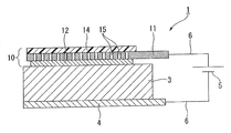
- FIG. 1 schematically shows an example of an auxiliary anode 10 of the present invention and a first embodiment of a corrosion prevention structure for a concrete structure using the auxiliary anode 10.
- the auxiliary anode 10 is installed by sticking the first electrolyte layer 12 to the surface of the concrete layer 3.
- the circuit wiring 6 is used to connect the positive electrode of the external power supply 5 to the conductive layer 11 of the auxiliary anode 10, and the circuit wiring 6 is used to connect the negative electrode of the external power supply 5 to the corrosion-protected body 4 to form an anticorrosion circuit. .
- adhesion means that objects are integrated by adhesion or adhesion.
- Adhesion means that objects can be peeled off at an intentional interface, but the objects are integrated with an adhesive strength that does not peel off in a natural state.
- Adhesion means that the objects are integrated with an adhesive strength that does not allow separation at the interface.
- the conductive layer 11 is a planar electrode that uniformly supplies a current supplied from the external power source 5 to the surface of the first electrolyte layer 12.
- the conductive layer 11 is formed by molding a material having high durability (corrosion resistance) against a gas such as oxygen and chlorine generated during energization and an electrolyte solution into a sheet shape.
- the material having high corrosion resistance used for the conductive layer 11 include metals such as platinum, titanium, nickel, lead and stainless steel, and carbon materials.
- metals having high corrosion resistance titanium is preferable because it has excellent corrosion resistance and is light and soft.
- Stainless steel is preferred because of its cost advantage. Stainless steel and titanium are more preferable when platinum or ruthenium is plated because they are excellent in corrosion resistance and conductivity.
- the metal used for the conductive layer 11 is preferably a metal foil.
- the thickness may be determined in consideration of availability, rigidity, weight, cost, and the like. For example, when a titanium foil is used, the thickness is preferably 20 ⁇ m to 500 ⁇ m. When using a stainless steel foil, the thickness is preferably 10 ⁇ m to 300 ⁇ m.
- the conductive layer becomes too heavy, and there is a possibility of peeling from the first electrolyte layer during long-term use. In addition, it is difficult to process due to its high rigidity. Further, when the auxiliary anode is applied to the bent surface, it is difficult to follow the bent surface.
- a metal ribbon a plurality of sheets can be used side by side in order to widen the width. In this case, it is preferable to electrically connect the metal ribbons with a conductor.
- a carbon material is light and easy to impart flexibility, and it is preferable because adjustment can ensure both conductivity and cost reduction.
- a sheet made of a carbon material having conductivity such as a graphite sheet obtained by processing graphite into a sheet, a carbon fiber woven fabric obtained by carbonizing organic fibers, a nonwoven fabric, a knitted fabric, etc.
- a sheet obtained by applying or impregnating a carbon material having conductivity such as carbon short fibers or carbon powder to a sheet-like fiber substrate such as carbon mixed paper, film substrate, woven fabric, nonwoven fabric, knitted fabric, or paper Can be used.
- some of the fibers may not be carbon fibers.
- the application means that the carbon material is mainly attached to the surface of the film base material or the fiber base material, and the impregnation means that the carbon material is attached to the surface of the fiber base material and penetrates into the inside. .
- the carbon material adheres to the surface of the fiber base material, the carbon material often penetrates into the gap between the fiber base materials.
- the conductivity of the conductive layer 11 is increased by the permeation of the carbon material, it is not necessary to strictly distinguish between coating and impregnation.
- it may be expressed as “application” including impregnation.
- a carbon coated sheet coated with a carbon material is preferable to use as the conductive layer 11 because it is advantageous in terms of cost and easy adjustment of conductivity.
- Metal, carbon material, synthetic resin, glass, cotton, hemp, wool, silk, etc. can be used as the material of the film substrate or fiber substrate carrying the carbon material of the carbon coated sheet.
- a base material made of a metal is preferable because it is excellent in conductivity, but it may be corroded by a gas such as oxygen or chlorine generated during energization and an electrolyte solution (electrolytic solution). For this reason, it is necessary to use platinum, titanium, etc. with high corrosion resistance, and it is disadvantageous in cost. Therefore, it is preferable that the carbon-coated sheet has a high corrosion resistance when a carbon material is supported on a synthetic resin base material, because the conductivity can be adjusted and the cost can be reduced.
- the conductive layer (hereinafter, also referred to as “fiber conductive layer”) made of a carbon-coated sheet in which a carbon material is applied to a fiber base material is composed of the conductive layer 11 and the first electrolyte layer 12 due to unevenness on the surface of the fiber base material. This is preferable because the contact area becomes large. And when the gel electrolyte layer which has adhesiveness in the 1st electrolyte layer 12, and is flexible and was excellent in the followability to unevenness, a part of gel permeates into the crevice of a fiber base material, and adhesiveness is Increase.
- the gel electrolyte can efficiently ionize and receive positive charges sent from the positive electrode of the external power source 5 and can be efficiently transferred to the surface layer 3 of the corrosion-protected body 4 by ion conduction. Also, by applying a carbon material so that the gap between the fiber bases becomes a communication hole that allows gas to pass through, the gas generated when a large current is used during corrosion prevention is released from the gap between the fiber bases. Can do.
- the fiber base material of the fiber conductive layer conductive fibers such as metal fibers and carbon fibers, and non-conductive fibers such as glass fibers, animal fibers, vegetable fibers, synthetic resin fibers, woven fabrics, nonwoven fabrics, A fiber base material processed into a sheet such as knitted fabric or paper can be used.
- the fiber base material which consists of metal fibers is excellent in electroconductivity, it may corrode over time with generation
- a fiber base material made of synthetic resin fibers is preferable because of its high corrosion resistance.
- polyester resins such as polyethylene terephthalate (PET) and polyethylene naphthalate (PEN); polytetrafluoroethylene (PTFE) and ethylene-tetrafluoroethylene copolymer (ETFE).
- PET polyethylene terephthalate
- PEN polyethylene naphthalate
- PTFE polytetrafluoroethylene
- ETFE ethylene-tetrafluoroethylene copolymer
- fluorine resins acrylic resins; polyolefin resins such as polyethylene (PE) and polypropylene (PP); polyamide resins such as nylon, tetraacetyl cellulose (TAC); polyester sulfone (PES); polyphenylene sulfide (PPS); Polyarylate (PAr); Polysulfone (PSF); Polyetherimide (PEI); Polyacetal; Polyimide polymer; Polyethersulfone
- a conductive layer made of a carbon coated sheet in which a carbon material is coated on a film substrate is preferable because the amount of the carbon material coated can be accurately controlled.
- a carbon material does not permeate
- the substrate is a film, it may be difficult to apply the carbon material thickly.
- a carbon material may be applied to both sides of the film.
- a carbon base material may be embed
- the film conductive layer may be difficult to transmit gas depending on the film base material.
- a small voltage of 2 V or less is applied at the time of anticorrosion, the amount of gas generated is extremely small, and the generated gas permeates the film base material, which is not a problem.
- the amount of current that can be desalted or realkalized is required to prevent corrosion of reinforcing steel bars, it is generated by providing a large number of through holes 15 in the film conductive layer. Gas can escape.
- the inner diameter of the through hole 15 is preferably as small as possible if gas can be transmitted.
- the size is, for example, about 0.1 to 1 mm so as not to be clogged. Further, when the thickness of the carbon coating layer is large, it is preferable that the diameter of the through hole 15 is also relatively large.
- a known method such as punching, laser beam, drilling using a hot needle or a cold needle can be employed.
- Punching with a punch provides a hole having a relatively large diameter as compared with drilling using a hot needle or a cold needle. Perforation using a cold needle is in a state where the periphery of the hole is irregularly cleaved, and it is difficult to form a clear hole, but gas permeation is possible.
- Melt drilling using a laser beam or a hot needle is preferable because the peripheral edge of the hole is melted and solidified to form a clear hole, and even if the hole is provided with a high density, the strength of the conductive layer 11 is relatively small.
- the shape of the through hole 15 can be a circle, an ellipse, a square, a rectangle, a polygon, an indeterminate shape, or any other shape.
- a resin film is preferable because it has excellent corrosion resistance and can be easily formed into a film.
- resin which forms a resin film resin similar to resin which comprises the fiber base material mentioned above can be mentioned.
- the thickness of the film substrate used for the film conductive layer is not limited as long as the physical strength is ensured, but can usually be about 10 ⁇ m to 100 ⁇ m.
- the carbon material applied to the substrate of the fiber conductive layer and the film conductive layer is preferably carbon powder made of conductive carbon.
- the conductive carbon include graphite; various carbon blacks such as ketjen black, thermal black, acetylene black, channel black, and furnace black; carbon nanotubes and the like. Of these, graphite, ketjen black and carbon nanotubes are preferred because of their high conductivity. In particular, graphite that is inexpensive and has high conductivity is preferable.
- the carbon powder may contain short carbon fibers.
- carbon powder or carbon short fibers are dispersed in a solvent such as an organic solvent or water to make a paste, and the obtained carbon paste is
- coating and drying by coating methods such as immersion, a gravure coat, a bar coat, a screen coat
- coating and drying by coating methods such as immersion, a gravure coat, a bar coat, a screen coat
- coating and drying by coating methods such as immersion, a gravure coat, a bar coat, a screen coat
- coating and drying by coating methods such as immersion, a gravure coat, a bar coat, a screen coat
- coating and drying by coating methods such as immersion, a gravure coat, a bar coat, a screen coat
- coating and drying by coating methods such as immersion, a gravure coat, a bar coat, a screen coat
- coating and drying by coating methods such as immersion, a gravure coat, a bar coat, a screen coat
- coating and drying by coating methods such as immersion, a gravure coat, a bar coat, a screen coat
- coating methods
- the first electrolyte layer 12 is a charge transfer layer solidified in a sheet shape containing ions having positive and negative charges.
- the ions contained in the first electrolyte layer 12 move, or the charges move between these ions to move the charges by ionic conduction.
- Main electrolytes used for the first electrolyte layer 12 include gel electrolytes in which an electrolyte solution is held in a resin matrix, cations such as imidazolium ions and pyridinium ions, and anions such as BF 4 ⁇ and PF 6 ⁇ .
- Polymer electrolytes such as an intrinsic polymer electrolyte in which a lithium salt such as bis (trifluoromethanesulfonyl) imide lithium (LiTFSI) is held in an ionic gel or polyether resin in which an ionic liquid (organic room temperature molten salt) is held in a resin matrix
- a lithium salt such as bis (trifluoromethanesulfonyl) imide lithium (LiTFSI)
- an ionic liquid organic room temperature molten salt
- the gel electrolyte is obtained by gelling (solidifying) an electrolyte in a resin matrix by adding a polymer, adding an oil gelling agent, polymerization containing polyfunctional monomers, a crosslinking reaction of the polymer, or the like.
- the first electrolyte layer 12 is formed by adhering the auxiliary anode 10 to the ion-permeable surface layer 3 existing on the surface of the object to be protected 4 such as a concrete layer or a paint film, and from the positive electrode of the external power source 5 to the conductive layer 11. This is a layer that converts the movement of electrons (electron conduction) due to the current supplied to ionic conduction to transfer charges to the surface layer 3 of the corrosion-protected body 4.
- the first electrolyte layer 12 is a gel electrolyte that is a flexible pressure-sensitive adhesive layer, when the auxiliary anode 10 is attached to the surface layer of the body 4 to be protected, for example, the concrete layer 3, the minute unevenness of the concrete layer 3.
- the thickness of the gel electrolyte layer used for the first electrolyte layer 12 is not particularly limited, but is preferably 100 ⁇ m to 1000 ⁇ m. Although there is no particular problem if the first electrolyte layer 12 is thicker than this range, it is disadvantageous in terms of cost. If the first electrolyte layer 12 is thinner than this range, the adhesive strength may be insufficient. Further, when the electrolyte solution in the gel electrolyte is absorbed by the concrete layer 3, the charge transfer capability may be lowered.
- the gel electrolyte used for the first electrolyte layer 12 has an adhesive property in which a solvent and an electrolyte salt, preferably a wetting agent are held in a resin matrix obtained by copolymerizing a polymerizable monomer with a crosslinkable monomer.
- a conductive polymer gel electrolyte is preferable.
- the polymer gel electrolyte needs to be able to maintain a shape by holding a liquid solvent or the like in a three-dimensional network structure of polymer chains in which polymer chains are physically or chemically bonded.
- the polymer gel electrolyte used for the first electrolyte layer 12 can form a flexible polymer three-dimensional network structure (resin matrix) by appropriately designing the polymer three-dimensional network structure.
- the resin matrix of the polymer gel electrolyte used for the first electrolyte layer 12 is subjected to a crosslinking treatment with a crosslinking agent or a polymerizable monomer and a crosslinking monomer are polymerized in order to increase cohesion. It is preferable to crosslink.
- a resin matrix in which polymer chains are three-dimensionally cross-linked is excellent in the ability to retain a solvent and a wetting agent. Thereby, it is possible to hold
- the polymerizable monomer forming the resin matrix is not particularly limited as long as it is a monomer having one polymerizable carbon-carbon double bond in the molecule.
- (Meth) acrylic acid derivatives (meth) acrylamide, N-methyl (meth) acrylamide, N-ethyl (meth) acrylamide, N-propyl (meth) acrylamide, N-butyl (meth) acrylamide, N, N-dimethyl ( (Meth) acrylamide, diacetone acrylamide, (meth) acrylamide derivatives such as N, N-dimethylaminopropyl (meth) acrylamide, t-butylacrylamide sulfonic acid, and salts thereof; N-vinylpyrrolidone, N-vinylformamide, N-vinylacetoa N- vinylamide derivatives such as de, vinyl sulfonic acid, and sulfonic acid monomers such as allyl sulfonic acid and salts thereof.
- (meth) acryl means acryl or methacryl.
- crosslinkable monomer that is polymerized and cross-linked with the polymerizable monomer
- a monomer having two or more double bonds having a polymerizable property in the molecule it is preferable to use a monomer having two or more double bonds having a polymerizable property in the molecule.
- polyfunctional (meth) acrylamide monomers such as methylene bis (meth) acrylamide, ethylene bis (meth) acrylamide, N, N-methylene bisacrylamide, N-methylol acrylamide; (poly) ethylene glycol di
- Polyfunctional (meth) acrylate monomers such as (meth) acrylate, (poly) propylene glycol di (meth) acrylate, glycerin di (meth) acrylate, glycerin tri (meth) acrylate, glycidyl (meth) acrylate; tetraallyloxy Ethane; diallylammonium chloride and the like.
- the content of the crosslinkable monomer is preferably 0.005 to 10 parts by weight with respect to 100 parts by weight of the resin matrix obtained by polymerizing and crosslinking the polymerizable monomer and the crosslinkable monomer.
- the content of the crosslinkable monomer in the resin matrix is small, there are few network crosslinking points connecting the main chains, and a polymer gel electrolyte excellent in shape retention may not be obtained.
- the content of the crosslinkable monomer is large, the network cross-linking points connecting the main chains will increase, and a polymer gel electrolyte with high apparent shape retention will be obtained, but the polymer gel electrolyte will become brittle and will have a tensile force.
- the polymer gel electrolyte is likely to be cut or broken due to the compression force.
- the polymer main chain becomes hydrophobic due to an increase in the number of cross-linking points, making it difficult to stably hold the solvent encapsulated in the network structure, and bleeding may easily occur.
- a prepolymerized resin matrix is newly impregnated with a polymerizable monomer and a crosslinkable monomer, and polymerized again. You may form the three-dimensional structure which mutually penetrated different resin matrices.
- the prepolymerized resin matrix may or may not be cross-linked.
- the solvent that can be used for the polymer gel electrolyte is preferably a polar solvent having a high boiling point, a low vapor pressure at room temperature, and compatibility with the polymerizable monomer and the crosslinkable monomer.
- solvents include water, alcohols such as methanol, ethanol and isopropanol, cellosolves such as methyl cellosolve, ethyl cellosolve and butyl cellosolve, N, N-dimethylformamide, N, N-dimethylacetamide, N, N′-.
- Examples thereof include amides such as dimethyl-2-imidazolidinone and N-methyl-2-pyrrolidone, sulfolane and dimethyl sulfoxide.
- the solvent contained in the polymer gel electrolyte is preferably 5 to 50% by weight, more preferably 5 to 40% by weight. If it is less than this range, the flexibility of the polymer gel electrolyte is low, and an electrolyte salt can hardly be added, so that good conductivity cannot be obtained. In addition, exceeding this range greatly exceeds the equilibrium solvent retention amount of the polymer gel electrolyte, which may cause bleeding of the solvent. In addition, a solvent that cannot be retained flows out, and the change in physical properties over time may increase.
- the polymer gel electrolyte used for the first electrolyte layer 12 is a hydrogel in which water as a solvent and an electrolyte salt, preferably a wetting agent, are retained in a hydrophilic resin matrix. Moisture and solvent are common. Therefore, ion conduction is likely to occur at the interface between the concrete layer 3 and the first electrolyte layer 12, which is preferable.
- the hydrogel can hold the electrolyte salt dissolved in water at the molecular level in the resin matrix.
- the aqueous electrolyte solution has a high charge transfer speed and can easily impart flexibility and adhesiveness.
- the water content of the hydrogel used for the first electrolyte layer 12 is usually 5 to 50% by weight, preferably 10 to 30% by weight.
- the flexibility of the hydrogel may be reduced. Moreover, ion conductivity may fall and it may be inferior to the capability to move an electric charge.
- the water content of the hydrogel is high, the water exceeding the water content that can be retained by the hydrogel may be detached or dried to cause the gel to shrink or the change in physical properties such as ion conductivity may increase. Moreover, it may be too flexible and inferior in shape retention.
- the wetting agent When the wetting agent is included in the hydrogel used for the first electrolyte layer 12, it is possible to suppress a decrease in the water content of the hydrogel. From the viewpoint of tackiness and shape retention, it is preferable to adjust the wetting agent to a range of 5 to 80% by weight, preferably about 20 to 70% by weight. If the content of the wetting agent in the hydrogel is low, the moisture retention capacity of the hydrogel will be poor, the moisture will easily evaporate, the hydrogel will not be stable over time, and the flexibility will be poor and the adhesiveness will decrease. Sometimes. When the content of the wetting agent is large, the viscosity becomes too high at the time of producing the hydrogel, the handleability is lowered, and bubbles may be mixed in at the time of forming the hydrogel. In addition, the resin matrix and water content are relatively small, and the shape retention and ion conductivity may be reduced.
- the wetting agent is not particularly limited as long as it improves the retention of the solvent.
- polyhydric alcohols such as ethylene glycol, propylene glycol, butanediol, glycerin, pentaerythritol, sorbitol; these polyhydric alcohols Polyols polymerized using one or more of these as monomers; saccharides such as glucose, fructose, sucrose, and lactose.
- the wetting agent may be used alone or in combination of two or more.
- polyhydric alcohols are preferred because they impart elasticity to the hydrogel in addition to the action of retaining moisture.
- glycerin is particularly suitable in terms of long-term water retention.
- Polyhydric alcohols can be used by selecting one or more from these.
- those which are liquid at normal temperature are more preferable because they are excellent in improving the elasticity of the hydrogel and handling in production.
- known fillers such as titanium oxide, calcium carbonate, and talc may be added.
- the electrolyte salt contained in the hydrogel used for the first electrolyte layer 12 can be arbitrarily selected from electrolyte salts commonly used for charge transport. Such a salt is not particularly limited as long as ion conductivity can be imparted to the hydrogel.
- a halogenated alkali metal salt such as sodium halide such as NaCl, potassium halide such as KCl, or halogenated salt.
- Halogenated alkaline earth metal salts such as magnesium and calcium halides, other metal halides such as LiCl; sulfates, nitrates, phosphates and chlorates of various metals such as K 2 SO 4 and Na 2 SO 4 , Perchlorates, hypochlorites, chlorites, ammonium salts, fluorine-containing electrolyte salts such as LiPF 6 , LiBF 4 , LiTFSI, and inorganic salts such as various complex salts; acetic acid, benzoic acid, lactic acid, tartaric acid, etc.
- Monovalent organic carboxylates Monovalent organic carboxylates; monovalent or divalent or higher salts of polyvalent carboxylic acids such as phthalic acid, succinic acid, adipic acid and citric acid; Metal salts of organic acids such as phonic acid and amino acids; organic ammonium salts; salts of polymer electrolytes such as poly (meth) acrylic acid, polyvinyl sulfonic acid, poly t-butylacrylamide sulfonic acid, polyallylamine, and polyethyleneimine It is done.
- the hydrogel is insoluble or dispersed, it can be used that dissolves in the hydrogel over time, such as silicate, aluminate, metal oxide. And metal hydroxides.
- the content of the electrolyte salt in the hydrogel is preferably 0.01 to 20% by mass, and more preferably 0.1 to 10% by weight. If it is higher than this range, it is difficult to completely dissolve the electrolyte salt in water, and it may be precipitated as crystals in the hydrogel, or the dissolution of other components may be inhibited. If it is lower than this range, the ion conductivity may be inferior. If the hydrogel used for the first electrolyte layer 12 contains an electrolyte, it becomes ion-conductive and can move charges, but if it also contains a redox agent, the movement of charges becomes smoother.
- redox agent examples include organic materials such as a quinone-hydroquinone mixture, and inorganic materials such as S / S 2 ⁇ and I 2 / I ⁇ .
- organic materials such as a quinone-hydroquinone mixture
- inorganic materials such as S / S 2 ⁇ and I 2 / I ⁇ .
- tetraalkylammonium iodide, pyridinium iodide, iodine compounds such as quaternary ammonium compounds, such as imidazoline iodide also suitably used .
- alkalis such as NaOH and KOH, may be included.
- Examples of the method for producing the hydrogel used for the first electrolyte layer 12 include dissolving or dispersing in water a polymerized monomer, a crosslinkable monomer, a wetting agent, a polymerization initiator, and an electrolyte salt.
- Crosslinking, polymerizing method, polymerizing monomer, crosslinkable monomer, wetting agent and polymerization initiator are dissolved or dispersed in water and crosslinked and polymerized to impregnate electrolyte salt in resin matrix
- a method of producing a resin matrix by crosslinking reaction of a crosslinking agent with a crosslinking agent may appropriately contain a preservative, a fungicide, a rust inhibitor, an antioxidant, a stabilizer, a surfactant, a colorant, and the like. .
- a known method can be adopted as a method of laminating the first electrolyte layer 12.
- coating on the conductive layer 11 by coating methods such as a gravure coat, a bar coat, a screen coat, can be mentioned.
- the hydrogel sheet has adhesiveness, so that the hydrogel sheet can be attached to the conductive layer 11 as it is.
- This method is preferable when the auxiliary anode 10 is mass-produced by roll-to-roll using the roll wound body conductive layer 11 and the roll wound hydrogel sheet.
- the conductive layer 11 is prepared by dissolving or dispersing in water a polymerized monomer, a crosslinkable monomer, a wetting agent, a polymerization initiator, and an electrolyte salt. It may be applied to form a sol-like electrolyte layer and then gelled by radical polymerization.
- the auxiliary anode 10 is mass-produced by roll-to-roll, when the first electrolyte layer 12 is integrated and wound on a roll, or when it is cut into sheets and stacked, it is exposed to the outside of the first electrolyte layer 12. It is preferable to laminate release paper on the surface to be processed.
- a protective layer 14 is laminated on the conductive layer 11.
- the protective layer 14 is located on the surface of the auxiliary anode 10 and blocks water and air, thereby preventing the conductive layer 11 and the first electrolyte layer 12 from being soiled, deteriorated, or damaged. Therefore, the protective layer 14 is preferably formed so as to cover the entire surface of the conductive layer 11 and the first electrolyte layer 12.
- the protective layer 14 is preferably a dry laminated resin film or an extrusion laminated resin.
- the resin is previously formed into a flat member such as a sheet or a plate and the periphery thereof is bonded with an epoxy adhesive or the like.
- Examples of the resin for forming the protective layer 14 include fluorine resins such as polyvinylidene fluoride (PVDF), polytetrafluoroethylene (PTFE) and ethylene-tetrafluoroethylene copolymer (ETFE), epoxy resins and methyl methacrylate (MMA).
- PVDF polyvinylidene fluoride
- PTFE polytetrafluoroethylene
- ETFE ethylene-tetrafluoroethylene copolymer
- MMA methyl methacrylate
- Acrylic resins such as) are preferred because they are excellent in contamination prevention and weather resistance.
- polyesters such as polyethylene terephthalate (PET) and polyethylene naphthalate (PEN), tetraacetyl cellulose (TAC), polyether sulfone (PES), polyphenylene sulfide (PPS), polycarbonate (PC), polyarylate (PAr), poly Resins such as sulfone (PSF), polyetherimide (PEI), polyacetal, transparent polyimide, and polyethersulfone can also be exemplified. Of these resins, a fluororesin is preferable because it is excellent in weather resistance.
- the fluororesin since the fluororesin has a low gas barrier property, it does not apply a process such as providing a large number of holes, so that a gas such as oxygen or chlorine that is generated when a current of about 10 mA to 30 mA is applied to prevent corrosion.
- the protective layer 14 can be discharged. When these resins are formed into a film, the protective layer 14 can be laminated by dry lamination, which is preferable when the auxiliary anode 10 is mass-produced by roll-to-roll. Such a film is preferably stretched to increase the strength.
- the thickness of the protective layer 14 is preferably thin from the viewpoint of the ability to discharge gases such as oxygen and chlorine generated during corrosion prevention and the cost.
- the thickness of the protective layer 14 is selected in the range of 10 to 200 ⁇ m, preferably 20 to 100 ⁇ m.
- the protective layer 14 may be formed by laminating a plurality of same or different types of resins.
- the protective layer 14 may be colored or may have a design such as character information or a pattern. In particular, it is preferable that the color is a gray color similar to the color of the surface of the concrete layer 3 because the auxiliary anode 10 is not conspicuous.
- a method for forming the protective layer 14 is usually formed into a film and laminated on the conductive layer 11 using an adhesive. When the conductive layer 11 is a film conductive layer, the surface of the film base material on which no carbon material is applied may be used as the protective layer 14.
- the auxiliary anode 10 of the present invention in addition to those containing iron such as steel (stainless steel, etc.), those containing nickel, titanium, copper, zinc, etc. can be protected against corrosion. . Further, the auxiliary anode 10 is adhered to a surface layer made of an ion-permeable oxide film such as rust present directly or on the surface of a metal covered with a concrete layer or a paint film or a bare metal. These can also be anticorrosive. When the to-be-protected body 4 is embedded in the concrete layer 3, there is a gel-like substance containing moisture in the extremely small voids in the concrete layer 3.
- the ions contained in the gel substance are mainly OH ⁇ , Na + , Ca 2+ , K + and the like.
- sodium chloride is infiltrated into the concrete layer of the structure near the sea where corrosion protection is highly necessary. That is, the concrete layer 3 is a solid electrolyte layer having a remarkably large impedance, and can function as an ion conductive layer by these ions.
- the to-be-corroded body 4 to which the auxiliary anode 10 of the present invention is applicable can also be applied to the to-be-corroded body having a coating film formed on the surface.
- the coating film of the paint looks like an insulating layer, the surface of the coating film that requires anticorrosion has many cracks and fine pores into which moisture that causes corrosion enters. These cracks and holes penetrate to the body to be protected. Since the cracks and holes cannot block moisture and air, moisture is present. Accordingly, ions can move in this portion and become ion conductive, and therefore, the auxiliary anode 10 of the present invention can be attached to a paint film to prevent corrosion.
- the anticorrosion structure 1 of the concrete structure of the present embodiment has the auxiliary anode 10 attached to the surface layer 3 of the concrete structure using the first electrolyte layer 12, and the conductive layer 11 of the auxiliary anode 10 is connected to the external power source 5.
- the negative electrode of the external power source 5 is connected to the corrosion-protected body 4 using the circuit wiring 6.
- the circuit wiring 6 preferably has corrosion resistance against anodic dissolution, and examples thereof include nickel alloys such as carbon, titanium, stainless steel, platinum, tantalum, zirconium, niobium, nickel, monel and inconel. Of these, titanium is preferred because it is readily available and is resistant to anodic dissolution over a wide range of potentials. Also, an aluminum wire or copper wire that is not resistant to anodic dissolution can be used by being coated with a resin layer.
- the anticorrosion structure 2 of the concrete structure of this embodiment is different from the first embodiment in that the adhesive force that can be attached to the conductive layer 11 is provided on the surface of the conductive layer 11 on which the first electrolyte layer 12 is not laminated. That is, the second electrolyte layer 13 is laminated.
- the second electrolyte layer 13 performs conversion from electron conduction to ion conduction at the interface with the conductive layer 11.
- Electron conduction of positive charges due to current supplied from the external power source 5 to the conductive layer 11 is converted into ion conduction at the interface between the first electrolyte layer 12 and the conductive layer 11 of the second electrolyte layer 13. Then, the positive charge converted into ionic conduction at the interface of the second electrolyte layer 13 passes through the conductive layer 11 and the positive charge converted into ionic conduction at the interface of the first electrolyte layer 12 together with the concrete layer 3. To move efficiently.
- the conductive layer 11 has a large number of communication holes 16 through which ions having a positive charge converted from electron conduction to ion conduction by the second electrolyte layer 13 can pass.
- a carbon material can be applied so that minute gaps between the fibers communicate with each other to form the ion permeable communication holes 16.
- the conductive layer 11 is a fiber electrode because the contact area between the conductive layer 11 and the first electrolyte layer 12 and the second electrolyte layer 13 increases due to surface irregularities, and ions easily move between the electrolyte layers. .
- the conductive layer 11 is a film conductive layer
- a carbon material is applied to both surfaces of the film base, and the through holes 16 are drilled to form the ion-permeable conductive layer 11. It is preferable that a part of the first and second electrolyte layers 12 and 13 enters the inside of the through hole 16 and directly contacts them. Accordingly, the inner diameter of the through hole 16 may be small as long as ions can be transmitted, but is preferably about 0.3 to 10 mm, for example. Moreover, when the thickness of the conductive layer 11 is large, it is preferable that the diameter of the through hole 16 is also relatively large.
- first and second electrolyte layers 12 and 13 are gel electrolytes containing an electrolytic solution (electrolyte solution)
- electrolytic solution electrolytic solution
- the first electrolyte layer 12 is not necessarily in direct contact with the second electrolyte layer 13 in the through hole 16 of the conductive layer 11.
- the through hole 16 can be formed in the same manner as the through hole 15.
- the punching perforation with a punch provides a hole having a relatively large diameter as compared with the perforation using a hot needle or a cold needle, and the first electrolyte layer 12 is easily in direct contact with the second electrolyte layer 13.
- Perforation using a cold needle is in a state where the periphery of the hole is randomly cleaved, and it is difficult to form a clear hole, but when a gel electrolyte is used, ions can permeate through the cleft.
- the shape of the through-hole 16 may be a circle, an ellipse, a square, a rectangle, a polygon, an indeterminate shape, or any other shape.
- the through hole 16 is effective when the ion permeability is insufficient even when the conductive layer 11 is a fiber conductive layer.
- the second electrolyte layer 13 may be different from the first electrolyte layer 12, but it is preferable to use the same electrolyte. Since the second electrolyte layer 13 does not require the function of adhering to the concrete layer 3, an electrolyte having no adhesive force such as a polyacrylate or a polyether resin holding an electrolyte solution is also used. be able to. However, it is preferable that the second electrolyte layer 13 has adhesive strength because it can be laminated without using a separate adhesive when laminated with the conductive layer 11 and with the protective layer 14. In this embodiment, the protective layer 14 is laminated on the second electrolyte layer 13 so that the second electrolyte layer 13 is wetted, dried, soiled, deteriorated, or damaged.
- the protective layer 14 preferably covers the entire surface of the second electrolyte layer 13. In order to prevent the deterioration of the second electrolyte layer 13, the protective layer 14 preferably reflects or absorbs ultraviolet light and does not transmit it.
- Example 1 of the auxiliary anode 10 was produced according to the following procedure, and the change in current when a constant voltage was applied by a constant voltage power supply was measured.
- the reason for applying the constant voltage is to keep 1 V at which no chlorine gas or oxygen gas is generated and to prevent the measurement result from being affected.
- a powdery graphite was dispersed in an organic solvent on a 38 ⁇ m thick PPS film, a conductive carbon paste blended with a binder was applied and dried to form a conductive layer 11 having a width of 60 mm and a length of 80 mm.
- the amount of carbon powder deposited was about 20 g / m 2 by dry weight.
- the thickness of the conductive layer 11 was 15 ⁇ m.
- the obtained conductive layer 11 was punched with a hot needle from the PPS film surface, and a large number of through holes 15 were formed in the conductive layer 11.
- a protective layer 14 was obtained by dry laminating a 25 ⁇ m thick ETFE film, which was colored gray by blending a pigment on the PPS film surface of the conductive layer 11. In dry lamination, the adhesive was gravure coated in a dot shape.
- a hydrogel sheet (“Technogel SR-R” manufactured by Sekisui Plastics Co., Ltd.) having a thickness of about 0.8 mm, a width of about 50 mm, and a length of about 50 mm was used as the first electrolyte layer 12.
- the carbon powder surface of the conductive layer 11 is adhered to the first electrolyte layer 12 so that the margin around the three sides of the conductive layer 11 is 5 mm and the margin of one side is 25 mm, and the auxiliary shown in FIG. Example 1 of the anode 10 was produced.
- a copper tape having a width of 10 mm was attached to the conductive layer 11 exposed at a width of 25 mm of the obtained auxiliary anode 10 with a conductive adhesive along one side in the longitudinal direction.
- This copper tape is a place where an electric current discharge point (a positive electrode connection portion of the external power source 5) is installed, and is a power supply material that reduces a voltage difference applied when energizing a portion far from the discharge point of the conductive layer 11 and a portion near it. is there.
- the first electrolyte layer 12 of the auxiliary anode 10 was bonded to the concrete layer 3 made of a 60 mm square mortar with a thickness of 20 mm to which an iron plate 4 having a width of 60 mm and a length of 80 mm was adhered, with the three sides aligned.
- the cement ordinary Portland cement was used.
- the specification of the mortar was cement 1, standard sand 3, and water 0.5 according to the mortar composition described in JIS R 5201 “Physical test method for cement”. The water cement ratio in this formulation is 0.50.
- the positive electrode of the external power source 5 was connected to the copper tape of the conductive layer 11 of the auxiliary anode 10 with a conductive wire 6 made of a resin-coated copper wire, and the negative electrode of the external power source 5 was connected to the iron plate 4 with a similar conductive wire 6.
- the periphery of the protective layer 14 and each connection portion of the copper tape 6 and the copper wire 6 of the conductive layer 11 are sealed with a fluororesin film and an epoxy adhesive, and the anticorrosion structure 1 of the concrete structure shown in FIG. It was set as Example 1 of the 1st form example.
- a non-resistance ammeter (AM-02 manufactured by Toho Giken Co., Ltd., not shown) is provided in the middle of the lead 6 connecting the external power source 5 and the auxiliary anode 10, and the conductive layer 11 and the iron plate 4 are used in an environment of 60 ° C. and RH 85%. In the meantime, a voltage of 1 V was applied, and the amount of current was measured. The result is shown in FIG. According to the constant voltage energization test, a current of 3 mA / m 2 or more was flowing over a period of 200 days (4800 hours) or more.
- the adhesion performance of the concrete layer 3, the 1st electrolyte layer 12, and the conductive layer 11 with respect to long-term electricity has practical durability. If a current of 3 mA / m 2 or more flows, it is possible to prevent corrosion of the reinforcing steel whose corrosion progresses shallowly or to perform preliminary corrosion protection of the reinforcing steel on which the passive film is formed. Therefore, it was shown that the auxiliary anode of the present invention and the anticorrosion structure and anticorrosion method for a concrete structure using the auxiliary anode can be used for such anticorrosion.
- Comparative Example 1 of the anticorrosion structure 1 of the concrete structure was produced in the same manner as in Example 1 except that the conductive layer 11 was adhered to the concrete layer 3.
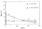
- a voltage of 1 V was applied to each of Example 1 and Comparative Example 1, and the amount of current was measured. The result is shown in FIG. In FIG.
- Example 1 (carbon / gel) is indicated by reference A
- Comparative Example 1 (carbon / mortar) is indicated by reference B.
- the anticorrosion structure 1 of Example 1 had a smaller initial current amount than the anticorrosion structure of Comparative Example 1, but reversed in about 400 hours (indicated by symbol C in FIG. 4), and from the start of measurement. The amount of current was stable up to 500 hours, and almost no change in current was observed. In Comparative Example 1, the reason why the initial current amount was large and then gradually decreased is considered to be the influence of moisture in the non-shrinkable cement.
- Example 1 is further added with salt.
- a constant current of 300 mA / m 2 was passed through the auxiliary anode 10 of Example 1 with a constant current power supply to measure the power supply voltage.
- the results are shown in FIG.
- the voltage was relatively stable at 3 to 4 V for 150 hours after the start of energization, but after that, the voltage gradually increased, and there was no voltage response around 230 hours. This behavior is presumed that the generated gas stays in the auxiliary anode 10 and the conductive layer 11 and the first electrolyte layer 12 are peeled off or the conductive adhesive of the copper tape is deteriorated.
- Example 2 of the auxiliary anode 10 was produced by dry laminating a PP nonwoven fabric having a basis weight of 30 g / m 2 between the ETFE film as the protective layer 14 and the conductive layer 11.
- Example 2 of the anticorrosion structure 1 was produced in the same manner as Example 1 of the anticorrosion structure 1 of a concrete structure, and a constant current of 300 mA / m 2 was passed.
- the results are shown in FIG. As a result, the voltage was stable at 3 V to 3.5 V over 40 days, and the voltage increasing tendency as shown in FIG. 5 was not observed.
- the auxiliary anode 10 of the present invention can be applied to desalting treatment and realkalization without using a protective layer 14 with high air permeability.
- elemental analysis by EPMA clearly confirms that chlorine ions move in concrete. Therefore, by using a highly permeable layer as the protective layer 14, the auxiliary anode of the present invention and the anticorrosion structure and anticorrosion method for concrete structures using the same can be positively desalted and realkalized. It is.
- the auxiliary anode of the present invention and the anticorrosion structure and anticorrosion method for concrete structures using the same can be applied to anticorrosion due to a large current with respect to reinforcing steel bars.
- the present invention as a first stage, the application of a voltage through which a large current that can be desalted or realkalized is applied to stop the degradation, and when a passive film is formed, It is possible to perform a conservative anticorrosion by applying a voltage with less generation of gas due to electrolysis.
- the protective layer 14 is laminated on the gas-permeable conductive layer 11 of the auxiliary anode 10, the conductive layer 11 and the protective layer 14 are bonded in a dot shape, It has been found that it is preferable to form a gas passage between the conductive layer 11 and the protective layer 14 by interposing an air-permeable layer such as a nonwoven fabric therebetween.
- the auxiliary anode of the present invention and the anticorrosion structure and anticorrosion method for a concrete structure using the auxiliary anode when flowing an anticorrosion current of 30 mA or less with less gas generation, It is possible to prevent corrosion for a long period of time with a simple configuration in which the gas passage between them is omitted.
- auxiliary anode of the present invention employs an electrolyte layer for contact with concrete, it does not come into direct contact with foreign matter. Therefore, since the auxiliary anode of the present invention is considered to reduce the influence of short circuit and electrolytic corrosion, the auxiliary anode 10 and a specimen were produced and tested.
- the specimen was a square prism with end faces of 100 mm both vertically and horizontally and a length of 600 mm.
- a 16 mm diameter rebar was embedded so that the ends were exposed from the center of both end faces of the concrete prism, and used as a standard specimen.
- the standard specimen was prepared by mixing 10 kg / m 3 of 357 mix sand and salt with ordinary cement to a water cement ratio of 50%.
- the iron wire of diameter 3mm was embedded so that a part might be exposed to the length direction center of one surface of a standard specimen.
- one of them was arranged in parallel with three iron wires, wound around a reinforcing bar, and embedded as a short-circuit specimen.
- the other was an electrolytic corrosion test specimen in which three iron wires were embedded in parallel on one surface of the specimen along the reinforcing bars.
- the auxiliary anode 10 of Example 3 was attached to the center in the length direction of the surface of the standard specimen to obtain Example 3 of the anticorrosion structure. Moreover, the auxiliary anode 10 of Example 3 was affixed on the three iron wires exposed on the surface of a short circuit specimen and an electrolytic corrosion specimen, and it was set as Example 4 and Example 5 of the anticorrosion structure, respectively.
- an auxiliary anode made of a 22 mm ⁇ 45 mm rhombus-like mesh titanium mesh (width 100 mm, length 100 mm) plated with a thin wire having a diameter of 1 mm is 10 mm thick.
- Comparative examples 2 to 4 having anticorrosion structures were bonded with mortar. Then, a constant current of 26 mA / m 2 was passed through each of Examples 3 to 5 and Comparative Examples 2 to 4 of the anticorrosion structure, and the voltage applied to the anticorrosion circuit every hour using a data logger and the natural potential of the reinforcing bar potential The amount of change with respect to the potential was measured. At the time of measurement, an AgCl affixing type reference electrode was affixed to the surface of the specimen without an auxiliary anode. The experiment temperature was fixed at 20 ° C., and the measurement was performed for 120 days for Examples 3 to 5 and 50 days for Comparative Examples 2 to 4.
- Example 3 using the standard specimen and Example 5 using the electrolytic corrosion specimen showed almost the same behavior.
- the voltage applied to Example 3 and Example 5 was 1.25V at the beginning of anticorrosion, then increased, and stabilized at 1.75V from about the 20th day.
- the voltage applied to Example 4 using the short-circuit specimen was 1.1 V at the beginning of corrosion prevention, increased with a substantially constant slope, and stabilized at about 1.7 V from the 70th day. That is, in all of Examples 3 to 5, a voltage of 2 V or less was applied, and there was a tendency to converge to a constant voltage.
- the voltage applied to Comparative Example 2 using the standard specimen was 2V at the beginning of anticorrosion, then increased with a substantially constant slope, reached 4V on the 50th day, and was still increasing. .
- the voltage applied to Comparative Example 3 using the short-circuited specimen was 2.5 V at the beginning of the corrosion prevention, and then increased with a substantially constant slope. On the 50th day, the voltage reached 3.8 V, and was further increasing. there were.
- Comparative Example 3 since the reinforcing bar and the titanium mesh were short-circuited by the iron wire, it was expected that the current would flow at a low voltage, but the voltage was actually twice or more that of Example 3.
- the amount of change of the rebar potential with respect to the natural potential was different in each of Examples 3 to 5, but increased with a substantially constant slope and was further increasing.
- the amount of change in potential at the beginning of corrosion protection was 200 mV for Example 3 using the standard specimen, 175 mV for Example 4 using the short-circuit specimen, and 280 mV for Example 5 using the electrolytic specimen.
- the amount of change in potential on the 120th day was 280 mV in Example 3, 225 mV in Example 4, and 350 mV in Example 5.
- Comparative Example 2 using the standard specimen was 300 mV at the beginning of anticorrosion, increased to 320 mV on the fifth day, and was almost constant thereafter.
- Comparative Example 3 using the short-circuit specimen, 125 mV at the beginning of the anticorrosion and increased to 160 mV in one day. Then, it remained constant from the ninth day to the fifteenth day, then gradually decreased, and became substantially constant at 150 mV on the 45th day.
- Comparative Example 4 using the electric corrosion test specimen, it was 200 mV at the beginning of anticorrosion and increased to 250 mV in one day. After that, it rose at a substantially constant slope, reached 300 mV on the 50th day, and was still rising.
- Example 4 using the short-circuited specimen with respect to Example 3 using the standard specimen was reduced by 13% at 25 mmV at the beginning of corrosion prevention, and reduced by 20% at 55 mmV on the 120th day. Smaller than Comparative Example 2.
- the voltage applied to the anticorrosion circuit tended to converge to a constant value. Therefore, it was found that in Example 3 using the short-circuit specimen, a short-circuit current did not flow and stable corrosion protection was possible.
- the comparative example 4 using the electrolytic corrosion test piece has a lower applied voltage than the comparative example 2 using the standard test piece because the iron wire functions as an anode and the area in contact with the concrete is increased. It is estimated to be. Therefore, it is estimated that the iron wire is strongly subjected to electric corrosion.
- Example 4 using the electrolytic corrosion specimen and Example 5 using the standard specimen exhibited almost the same voltage behavior. Therefore, it was found that Example 4 using the electrolytic corrosion specimen was able to stably prevent corrosion without being affected by the electrolytic corrosion portion.
- the surface of the concrete is covered with the auxiliary anode, so that there is no problem even if galvanic corrosion occurs and rust stains appear on the concrete surface.
- a power supply material made of copper tape is attached along one side in the longitudinal direction of the conductive layer, but a metal foil, a metal ribbon, a metal mesh such as a metal fiber woven fabric or expanded metal, and a conductive property.
- a conductive layer having a small surface resistance value such as a sheet made of a carbon material having, a power supply material need not be provided.
- a power supply material may be provided on two opposite sides in the longitudinal direction of the conductive layer, two sides and the middle in the longitudinal direction, or four sides of the conductive layer.
- the power supply material may be a thread instead of a tape.
- the material of the power supply material may also be titanium or stainless steel.
Landscapes
- Engineering & Computer Science (AREA)
- Chemical & Material Sciences (AREA)
- Architecture (AREA)
- Materials Engineering (AREA)
- Mechanical Engineering (AREA)
- Metallurgy (AREA)
- Organic Chemistry (AREA)
- Civil Engineering (AREA)
- Structural Engineering (AREA)
- Prevention Of Electric Corrosion (AREA)
- Building Environments (AREA)
Abstract
Priority Applications (2)
| Application Number | Priority Date | Filing Date | Title |
|---|---|---|---|
| US14/240,570 US9315906B2 (en) | 2011-08-26 | 2012-08-24 | Anode, corrosion-protecting structure for concrete constructions using this, and corrosion protection method |
| JP2013531266A JP6047493B2 (ja) | 2011-08-26 | 2012-08-24 | 補助陽極、それを用いたコンクリート構造物の防食構造および防食方法 |
Applications Claiming Priority (4)
| Application Number | Priority Date | Filing Date | Title |
|---|---|---|---|
| JP2011185123 | 2011-08-26 | ||
| JP2011-185123 | 2011-08-26 | ||
| JP2012030716 | 2012-02-15 | ||
| JP2012-030716 | 2012-02-15 |
Publications (1)
| Publication Number | Publication Date |
|---|---|
| WO2013031663A1 true WO2013031663A1 (fr) | 2013-03-07 |
Family
ID=47756153
Family Applications (1)
| Application Number | Title | Priority Date | Filing Date |
|---|---|---|---|
| PCT/JP2012/071379 Ceased WO2013031663A1 (fr) | 2011-08-26 | 2012-08-24 | Anode auxiliaire, construction anti-corrosion d'un corps structurel en béton à l'aide de cette dernière et procédé anti-corrosion |
Country Status (4)
| Country | Link |
|---|---|
| US (1) | US9315906B2 (fr) |
| JP (1) | JP6047493B2 (fr) |
| TW (1) | TW201319367A (fr) |
| WO (1) | WO2013031663A1 (fr) |
Cited By (9)
| Publication number | Priority date | Publication date | Assignee | Title |
|---|---|---|---|---|
| JP2014062782A (ja) * | 2012-09-20 | 2014-04-10 | Sho-Bond Corp | 照合電極及び自然電位測定方法 |
| JP2015059249A (ja) * | 2013-09-19 | 2015-03-30 | 積水化成品工業株式会社 | コンクリート構造物の電気防食方法 |
| JP2015059232A (ja) * | 2013-09-17 | 2015-03-30 | 藤森工業株式会社 | 導電性シートの面状陽電極 |
| JP2015059184A (ja) * | 2013-09-19 | 2015-03-30 | 積水化成品工業株式会社 | ハイドロゲル |
| WO2015152247A1 (fr) * | 2014-03-31 | 2015-10-08 | 藤森工業株式会社 | Cathode pour la prévention de la corrosion et structure de prévention de la corrosion d'une structure en béton et procédé de prévention de la corrosion employant cette dernière |
| WO2018201739A1 (fr) * | 2017-05-04 | 2018-11-08 | 深圳大学 | Dispositif de renforcement ayant une structure d'ancrage et procédé de renforcement |
| JP2020066754A (ja) * | 2018-10-22 | 2020-04-30 | 株式会社ケミカル工事 | 鉄筋コンクリートの電気防食構造および電気防食工法 |
| JP2021116219A (ja) * | 2020-01-29 | 2021-08-10 | デンカ株式会社 | 電気化学的処理工法及び電極用ユニットパネル |
| JP2022088156A (ja) * | 2020-12-02 | 2022-06-14 | デンカ株式会社 | 電気化学的処理システム及び電極用ユニットパネル |
Families Citing this family (5)
| Publication number | Priority date | Publication date | Assignee | Title |
|---|---|---|---|---|
| US20140202879A1 (en) * | 2013-01-24 | 2014-07-24 | The Euclid Chemical Company | Anode assembly for cathodic protection |
| US11840767B2 (en) * | 2017-05-01 | 2023-12-12 | Copsys Technologies Inc. | Cathodic protection of metal substrates |
| EP3762349B8 (fr) * | 2018-03-07 | 2022-08-31 | Structural Technologies | Procédé de traitement électrochimique de structures en béton affectées par asr |
| CN117127728B (zh) * | 2023-09-26 | 2025-08-05 | 柯丁森有限公司 | 一种电渗透防潮阳极及防潮系统 |
| CN119900031A (zh) * | 2025-02-25 | 2025-04-29 | 广州市克来斯特建材科技有限公司 | 一种牺牲阳极的材料及其制备方法 |
Citations (2)
| Publication number | Priority date | Publication date | Assignee | Title |
|---|---|---|---|---|
| JP2003027607A (ja) * | 2001-05-08 | 2003-01-29 | Toa Harbor Works Co Ltd | 鉄筋コンクリート構造物の電気防食方法 |
| JP2004190119A (ja) * | 2002-12-13 | 2004-07-08 | Oriental Construction Co Ltd | 防食補強コンクリート組立体、その防食方法及び組立方法 |
Family Cites Families (6)
| Publication number | Priority date | Publication date | Assignee | Title |
|---|---|---|---|---|
| TW369558B (en) * | 1994-01-28 | 1999-09-11 | Minnesota Mining & Mfg | Polymerized microemulsion pressure sensitive adhesive compositions and methods of preparing and using same |
| US5650060A (en) | 1994-01-28 | 1997-07-22 | Minnesota Mining And Manufacturing Company | Ionically conductive agent, system for cathodic protection of galvanically active metals, and method and apparatus for using same |
| JP3728086B2 (ja) * | 1998-01-20 | 2005-12-21 | オリエンタル建設株式会社 | 防食補強コンクリート組立体及び組立方法 |
| AT413822B (de) * | 2004-08-04 | 2006-06-15 | Wolfgang Schwarz | Galvanisches anodensystem für den korrosionsschutz von stahl und verfahren zu dessenherstellung |
| JP5091573B2 (ja) * | 2007-07-17 | 2012-12-05 | 富士重工業株式会社 | 蓄電デバイス |
| US7905993B2 (en) * | 2007-11-20 | 2011-03-15 | Miki Funahashi | Corrosion control method and apparatus for reinforcing steel in concrete structures |
-
2012
- 2012-08-23 TW TW101130632A patent/TW201319367A/zh unknown
- 2012-08-24 US US14/240,570 patent/US9315906B2/en active Active
- 2012-08-24 JP JP2013531266A patent/JP6047493B2/ja active Active
- 2012-08-24 WO PCT/JP2012/071379 patent/WO2013031663A1/fr not_active Ceased
Patent Citations (2)
| Publication number | Priority date | Publication date | Assignee | Title |
|---|---|---|---|---|
| JP2003027607A (ja) * | 2001-05-08 | 2003-01-29 | Toa Harbor Works Co Ltd | 鉄筋コンクリート構造物の電気防食方法 |
| JP2004190119A (ja) * | 2002-12-13 | 2004-07-08 | Oriental Construction Co Ltd | 防食補強コンクリート組立体、その防食方法及び組立方法 |
Cited By (16)
| Publication number | Priority date | Publication date | Assignee | Title |
|---|---|---|---|---|
| JP2014062782A (ja) * | 2012-09-20 | 2014-04-10 | Sho-Bond Corp | 照合電極及び自然電位測定方法 |
| JP2015059232A (ja) * | 2013-09-17 | 2015-03-30 | 藤森工業株式会社 | 導電性シートの面状陽電極 |
| JP2015059249A (ja) * | 2013-09-19 | 2015-03-30 | 積水化成品工業株式会社 | コンクリート構造物の電気防食方法 |
| JP2015059184A (ja) * | 2013-09-19 | 2015-03-30 | 積水化成品工業株式会社 | ハイドロゲル |
| US10227699B2 (en) | 2014-03-31 | 2019-03-12 | Fujimori Kogyo Co., Ltd. | Anode for preventing corrosion, and concrete structure corrosion prevention structure and corrosion prevention method employing same |
| JP2015193869A (ja) * | 2014-03-31 | 2015-11-05 | 藤森工業株式会社 | 防食用陽極、それを用いたコンクリート構造物の防食構造および防食方法 |
| KR20160138962A (ko) | 2014-03-31 | 2016-12-06 | 후지모리 고교 가부시키가이샤 | 방식용 양극, 그것을 사용한 콘크리트 구조물의 방식 구조 및 방식 방법 |
| WO2015152247A1 (fr) * | 2014-03-31 | 2015-10-08 | 藤森工業株式会社 | Cathode pour la prévention de la corrosion et structure de prévention de la corrosion d'une structure en béton et procédé de prévention de la corrosion employant cette dernière |
| TWI665335B (zh) * | 2014-03-31 | 2019-07-11 | Fujimori Kogyo Co., Ltd. | 防腐蝕用陽極、使用防腐蝕用陽極的混凝土構造物的防腐蝕構造以及防腐蝕方法 |
| KR102270325B1 (ko) * | 2014-03-31 | 2021-06-28 | 후지모리 고교 가부시키가이샤 | 방식용 양극, 그것을 사용한 콘크리트 구조물의 방식 구조 및 방식 방법 |
| WO2018201739A1 (fr) * | 2017-05-04 | 2018-11-08 | 深圳大学 | Dispositif de renforcement ayant une structure d'ancrage et procédé de renforcement |
| JP2020066754A (ja) * | 2018-10-22 | 2020-04-30 | 株式会社ケミカル工事 | 鉄筋コンクリートの電気防食構造および電気防食工法 |
| JP2021116219A (ja) * | 2020-01-29 | 2021-08-10 | デンカ株式会社 | 電気化学的処理工法及び電極用ユニットパネル |
| JP7025461B2 (ja) | 2020-01-29 | 2022-02-24 | デンカ株式会社 | 電気化学的処理工法及び電極用ユニットパネル |
| JP2022088156A (ja) * | 2020-12-02 | 2022-06-14 | デンカ株式会社 | 電気化学的処理システム及び電極用ユニットパネル |
| JP7089653B2 (ja) | 2020-12-02 | 2022-06-23 | デンカ株式会社 | 電気化学的処理システム及び電極用ユニットパネル |
Also Published As
| Publication number | Publication date |
|---|---|
| US9315906B2 (en) | 2016-04-19 |
| TWI560343B (fr) | 2016-12-01 |
| JPWO2013031663A1 (ja) | 2015-03-23 |
| TW201319367A (zh) | 2013-05-16 |
| JP6047493B2 (ja) | 2016-12-21 |
| US20140224670A1 (en) | 2014-08-14 |
Similar Documents
| Publication | Publication Date | Title |
|---|---|---|
| JP6047493B2 (ja) | 補助陽極、それを用いたコンクリート構造物の防食構造および防食方法 | |
| JP6238449B2 (ja) | 防食用陽極、それを用いたコンクリート構造物の防食構造および防食方法 | |
| KR100331344B1 (ko) | 이온전도제,전기화학적활성금속의음극방식시스템및이에따라방식처리된구조물 | |
| JP6141654B2 (ja) | 防食構造および防食方法 | |
| JP5688812B2 (ja) | コンクリート中の鋼の腐食保護 | |
| EP1802788B1 (fr) | Systeme anodique galvanique servant a proteger l'acier contre la corrosion et procede de production dudit systeme | |
| EP2665072A2 (fr) | Collecteur pour condensateur à double couche électrique | |
| JP2012021212A (ja) | 電子供給体 | |
| JP5501131B2 (ja) | 防食構造 | |
| Nikiforidis et al. | A study of different carbon composite materials for the negative half-cell reaction of the zinc cerium hybrid redox flow cell | |
| Merz et al. | The protection zone: A long-range corrosion protection mechanism around conducting polymer particles in composite coatings: Part I. polyaniline and polypyrrole | |
| WO2022263206A1 (fr) | Hydrogel électrolytique et son utilisation dans une cellule électrochimique | |
| CN104611707B (zh) | 一种用于地下管路的阴极保护方法及装置 | |
| TW554563B (en) | Polymer matrix material and electrochemical cell incorporating polymer matrix material | |
| Yu et al. | Construction of carboxylated aramid nanofiber protective layer for stable zinc anodes | |
| CN203256336U (zh) | 用于对钢筋混凝土结构进行阴极保护的加固装置 | |
| JP6274797B2 (ja) | 導電性シートの面状陽電極 | |
| Yang et al. | A robust in situ adaptive artificial interface for dead-lithium-free lithium metal batteries | |
| Song et al. | Preparation of GF/PFSA Hybrid Matrix Separators for High‐Stability Aqueous Zinc‐Ion Batteries | |
| JP4292282B2 (ja) | 電気防食用陽極ユニット及びこれを用いたコンクリート構造物 | |
| JP2018070764A (ja) | 鉄筋コンクリート電気防食用の外装塗料及び陽極被膜 | |
| EP3397295B1 (fr) | Dispositifs de contact avec un nerf | |
| CN121137651A (zh) | 一种插层电极及其凝胶界面构建方法 |
Legal Events
| Date | Code | Title | Description |
|---|---|---|---|
| 121 | Ep: the epo has been informed by wipo that ep was designated in this application |
Ref document number: 12827150 Country of ref document: EP Kind code of ref document: A1 |
|
| ENP | Entry into the national phase |
Ref document number: 2013531266 Country of ref document: JP Kind code of ref document: A |
|
| WWE | Wipo information: entry into national phase |
Ref document number: 14240570 Country of ref document: US |
|
| NENP | Non-entry into the national phase |
Ref country code: DE |
|
| 122 | Ep: pct application non-entry in european phase |
Ref document number: 12827150 Country of ref document: EP Kind code of ref document: A1 |