WO2013021789A1 - 内燃機関のピストン構造 - Google Patents
内燃機関のピストン構造 Download PDFInfo
- Publication number
- WO2013021789A1 WO2013021789A1 PCT/JP2012/068149 JP2012068149W WO2013021789A1 WO 2013021789 A1 WO2013021789 A1 WO 2013021789A1 JP 2012068149 W JP2012068149 W JP 2012068149W WO 2013021789 A1 WO2013021789 A1 WO 2013021789A1
- Authority
- WO
- WIPO (PCT)
- Prior art keywords
- piston
- pin hole
- pin
- peripheral surface
- main body
- Prior art date
- Legal status (The legal status is an assumption and is not a legal conclusion. Google has not performed a legal analysis and makes no representation as to the accuracy of the status listed.)
- Ceased
Links
Images





Classifications
-
- F—MECHANICAL ENGINEERING; LIGHTING; HEATING; WEAPONS; BLASTING
- F16—ENGINEERING ELEMENTS AND UNITS; GENERAL MEASURES FOR PRODUCING AND MAINTAINING EFFECTIVE FUNCTIONING OF MACHINES OR INSTALLATIONS; THERMAL INSULATION IN GENERAL
- F16J—PISTONS; CYLINDERS; SEALINGS
- F16J1/00—Pistons; Trunk pistons; Plungers
- F16J1/10—Connection to driving members
- F16J1/14—Connection to driving members with connecting-rods, i.e. pivotal connections
- F16J1/16—Connection to driving members with connecting-rods, i.e. pivotal connections with gudgeon-pin; Gudgeon-pins
-
- F—MECHANICAL ENGINEERING; LIGHTING; HEATING; WEAPONS; BLASTING
- F02—COMBUSTION ENGINES; HOT-GAS OR COMBUSTION-PRODUCT ENGINE PLANTS
- F02F—CYLINDERS, PISTONS OR CASINGS, FOR COMBUSTION ENGINES; ARRANGEMENTS OF SEALINGS IN COMBUSTION ENGINES
- F02F3/00—Pistons
Definitions
- the present invention relates to a piston structure of an internal combustion engine.
- a piston disposed in a cylinder of an internal combustion engine has a pin hole, and is connected to a connecting rod via a piston pin attached to the pin hole.
- the piston pin slides with the inner peripheral surface of the pin hole as the piston moves up and down.
- a minute gap is provided between the piston pin and the pin hole, and oil for preventing seizure of both is supplied to the gap.
- Patent Document 1 two communication grooves that connect the inner peripheral side and the outer peripheral side of the piston along the axial direction of the piston pin are formed at two locations on the upper half of the inner peripheral surface of the pin hole. It is disclosed. The two communication grooves are formed at symmetrical positions at an angle of 45 ° from the upper part of the pin hole. In Patent Document 1, it is assumed that the oil supply to the piston pin becomes sufficient by forming the two communication grooves at this position.
- the present invention has been made in view of these problems, and an oil film is held between the inner peripheral surface of the pin hole and the piston pin to suppress the hitting sound between the inner peripheral surface of the pin hole and the piston pin. It is an object of the present invention to provide a piston structure for an internal combustion engine that can be used.
- Patent Document 1 As a result of observing and analyzing the movement of the piston pin and oil inside the pin hole by the inventors' earnest research, as described in Patent Document 1, when the communication groove is provided symmetrically above and below the pin hole, As the piston pin turns along the inner peripheral surface of the pin hole, oil is discharged more than necessary from the communication groove on the anti-thrust side, and the inner peripheral surface of the pin hole and the piston pin may come into contact with each other. found. Therefore, the present inventors have conceived of eliminating the communication groove on the anti-thrust side in order to suppress the unnecessary discharge of oil.
- the present invention is a piston structure of an internal combustion engine in which a piston pin is inserted into a pin hole formed in a piston, and an inner peripheral surface of the pin hole is provided with a communication groove that communicates the inside and outside of the piston, The communication groove is provided only in the combustion chamber side and thrust side range of the piston on the inner peripheral surface of the pin hole.
- the communication groove that communicates the inside and the outside of the piston is provided only in the range on the combustion chamber side and the thrust side of the piston hole on the inner peripheral surface of the pin hole.
- the oil discharge is suppressed compared to the case where the communication groove is provided in the piston combustion chamber side and the anti-thrust side), and the oil is suitably held in the gap between the inner peripheral surface of the pin hole and the piston pin. Is done. Therefore, the hitting sound between the inner peripheral surface of the pin hole and the piston pin can be suppressed.
- the communication groove is provided to be biased toward the combustion chamber as the offset amount of the crankshaft rotation center with respect to the cylinder axis increases.
- the communication groove is biased toward the combustion chamber so that the gap between the inner peripheral surface of the pin hole and the piston pin is increased.
- the flow rate of the moving oil can be reduced. Therefore, the total amount of oil discharged from the gap between the inner peripheral surface of the pin hole and the piston pin can be reduced, and a large amount of oil can be held in the gap.
- the communication groove has an angle formed by a straight line connecting the axis of the pin hole and the center position in the circumferential direction of the communication groove and a straight line passing through the axis of the pin hole and perpendicular to the piston axis. It is preferable to be provided so that the angle is not less than 23 ° and not more than 23 °.
- oil can be suitably held between the inner peripheral surface of the pin hole and the piston pin.
- the piston includes a piston main body portion having a ring groove formed on an outer peripheral surface thereof, and a pair of pin boss portions extending downward from a lower surface of the piston main body portion and formed with the pin holes, It is preferable that the lower surface of the piston main body and the upper portion of the inner peripheral surface of the pin hole are continuous without a step.
- the lower surface of the piston main body and the upper part of the inner peripheral surface of the pin hole are smoothly continuous without a step, so that the oil adhering to the lower surface of the piston main body is retained in the pin hole. It becomes easy to flow into the peripheral surface. Therefore, the oil adhering to the lower surface of the piston main body can be suitably guided to the gap between the inner peripheral surface of the pin hole and the piston pin to maintain lubricity.
- a concave groove is formed in the circumferential direction on the inner peripheral surface of the pin hole, and the concave groove is connected to the communication groove and is formed only in a range closer to the crank chamber than the communication groove. It is good to do.
- an internal combustion engine piston structure capable of holding an oil film between an inner peripheral surface of a pin hole and a piston pin and suppressing a hitting sound between the inner peripheral surface of the pin hole and the piston pin. can do.
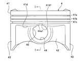
- FIG. 3 is a cross-sectional view taken along the line II in FIG. 2.
- (A) is an enlarged front view of a pin hole
- (b) is a cross-sectional view taken along the line II-II in FIG. It is an expanded sectional view of the lower surface vicinity of the piston main-body part in FIG.
- the internal combustion engine 1 includes a cylinder block 2 having a cylinder 21 and a crank chamber 22, a cylinder head 3 that closes the upper portion of the cylinder 21, a piston 4 installed in the cylinder 21, and a crank chamber.
- a crankshaft 5 disposed at 22, a connecting rod 6 that connects the piston 4 and the crankshaft 5, and a piston pin 7 that connects the connecting rod 6 and the piston 4 are mainly provided.
- the cylinder block 2 has an oil injection device 23 in the upper part of the crank chamber 22.
- the oil injection device 23 has a nozzle 23 a, and the oil injected from the nozzle 23 a is sprayed onto the piston 4. Oil adheres to the inner wall of the cylinder 21 due to, for example, scattering of the oil sprayed onto the piston 4.
- the oil injection device 23 is supplied with oil from an oil supply passage 24 provided in the cylinder block 2. Note that the method of supplying oil to the cylinder 21 is not limited to this.
- the inner wall of the cylinder 21 and the lower surface of the piston 4 are lubricated by oil scattered from the rotating crankshaft 5. Also good.
- the cylinder head 3 has an upper wall portion 31 that is recessed at a position corresponding to the cylinder 21.
- a space surrounded by the upper wall portion 31, the inner wall of the cylinder 21 and the upper surface of the piston 4 is a combustion chamber 32.
- An intake port 33 and an exhaust port 34 communicate with the upper wall portion 31.
- the intake port 33 and the exhaust port 34 are opened and closed by the intake valve 35 and the exhaust valve 36 at a predetermined timing.
- the crankshaft 5 rotates in the clockwise direction (see arrow y) in FIG.
- the axis CL of the cylinder 21 is offset by a predetermined distance L with respect to the axis 5a that is the rotation center of the crankshaft 5 on the side where the crankshaft 5 is directed from the upper fulcrum to the lower fulcrum.
- such an offset state is referred to as a normal offset
- the offset to the opposite side with respect to the axis CL is referred to as a reverse offset.
- the connecting rod 6 is a member that transmits the pressing force of the piston 4 due to the expansion of the fuel gas in the combustion chamber 32 to the crankshaft 5.
- a lower end 6 a of the connecting rod 6 is rotatably connected to a crank pin 5 b of the crankshaft 5.
- An upper end portion 6 b of the connecting rod 6 is connected to the piston 4 via a piston pin 7.
- the piston 4 is a substantially cylindrical member that is slidably fitted in the cylinder 21.
- the piston 4 reciprocates in the cylinder 21 by a pressing force due to the expansion of the fuel gas in the combustion chamber 32 and a lifting force due to the rotation of the crankshaft 5.
- the piston 4 is pressed against the inner wall of the cylinder 21 by the lateral force received from the connecting rod 6. More specifically, when the crankshaft 5 rotates clockwise in FIG. 1 (see arrow y), the component force of the pressing force acting in the direction of the axis CL of the cylinder 21 from the compression stroke to the expansion stroke (mainly the expansion stroke).
- the direction in which the thrust force acts (left side in FIG. 1) is referred to as the thrust side
- the opposite direction (right side in FIG. 1) is referred to as the anti-thrust side.
- the piston 4 includes a piston body portion 41 having a circular shape in plan view, a pair of pin boss portions 42 and 42 extending in a wall shape from the lower surface of the piston body portion 41, and the piston body. It mainly has a pair of skirt parts 43 and 43 that extend downward from the part 41 and connect the ends of the pair of pin boss parts 42 and 42.
- a pin hole 44 for inserting the piston pin 7 is formed in the approximate center of each pin boss portion 42.
- a hollow portion 45 is formed at the center lower portion of the piston 4 and is opened downwardly surrounded by the pair of pin boss portions 42 and 42 and the pair of skirt portions 43 and 43.
- the upper end portion 6 b of the connecting rod 6 is disposed in the hollow portion 45.
- the piston main body 41 has three ring grooves 41a, 41b, 41c on the outer peripheral surface thereof. Piston rings (not shown) for preventing combustion gas leakage are fitted in the upper two ring grooves 41a and 41b.
- the lower ring groove 41 c is fitted with an oil ring (not shown) for adjusting the amount of oil that lubricates between the inner wall of the cylinder 21 and the piston 4.
- the lower ring groove 41c is formed wider than the upper two ring grooves 41a and 41b, and an oil hole 45a serving as a lubricating oil passage communicating the inside and outside of the piston 4 is provided on the bottom surface thereof. Yes.
- a depression 41 e is formed on the upper surface of the piston body 41.
- an arcuate recess 41d1 is formed at a position corresponding to a pin hole 44 described later.
- the lower surface 41d of the piston main body 41 is located below the lower oil groove 41c.
- the recess 41d1 is formed along the arc shape of the pin hole 44 described later.
- the pair of pin boss portions 42, 42 are wall-shaped portions extending downward from the lower surface 41 d of the piston main body portion 41. As shown in FIG. 3, each pin boss portion 42 is disposed at a position closer to the center (a deepened position) than the surface of the piston main body portion 41.
- the pair of skirt portions 43, 43 are wall-like portions that extend downward from the lower surface 41 d of the piston main body portion 41 and connect both ends of the pair of pin boss portions 42, 42.
- the surface of each skirt portion 43 is provided flush with the surface of the piston main body portion 41.
- the pair of pin holes 44, 44 are through holes for inserting the piston pins 7, and are formed in the approximate center of the pin boss portion 42.
- the pin hole 44 is formed in the radial direction of the piston 4 in a top view.
- the axial direction of the pin hole 44 coincides with the axial direction of the crankshaft 5.
- a communication groove 46 that communicates the surface side of the piston 4 and the hollow portion 45 and a groove 47 that is recessed in the circumferential direction are formed on the inner peripheral surface 44 a of the pin hole 44.
- the communication groove 46 is a groove for guiding the oil transmitted from the inner wall of the cylinder 21 to the surface of the piston 4 into the pin hole 44.
- the communication groove 46 is formed in an arc shape in cross section.
- the communication groove 46 extends in parallel with the axial direction of the pin hole 44.
- FIG. 4 (a) when the pin hole 44 is viewed in the axial direction, the inner peripheral surface 44a is divided into four equal parts in the direction of the axis PL of the piston 4 and the direction perpendicular to the axis PL.
- the communication groove 46 is formed in a range on the combustion chamber 32 side and the thrust side of the inner peripheral surface 44a.
- channel of the axial direction of the pin hole 44 is not formed in the other three ranges among the inner peripheral surfaces 44a, but it has a smooth perfect circular arc shape.
- the axis PL of the piston 4 basically coincides with the axis CL (see FIG. 1) of the cylinder 21, but the piston 4 may be tilted within the cylinder 21 to be displaced from each other.
- the communication groove 46 is formed by an angle formed by a straight line L1 connecting the axis of the pin hole 44 and the center position in the circumferential direction of the communication groove 46 and a straight line L2 passing through the axis of the pin hole 44 and orthogonal to the axis PL of the piston 4. It is preferable that ⁇ (hereinafter referred to as “communication groove center angle ⁇ ”) is in a range of 20 to 23 °. This will be described in detail later with reference to FIG.
- the concave groove 47 is a groove for facilitating movement of oil that has entered the pin hole 44 in the circumferential direction. As shown in FIG. 4 (b), the concave groove 47 is formed on the inner peripheral surface 44a than the communication groove 46 (more specifically, the plane P1 including the lower end of the communication groove 46 and orthogonal to the axis PL. Rather than the crank chamber 22 side. Both end portions of the concave groove 47 are connected to the communication groove 46. Thereby, the movement of the oil between the communication groove 46 and the concave groove 47 becomes smooth.
- the upper portion 44a1 of the inner peripheral surface 44a of the pin hole 44 is smoothly continuous with an arc-shaped recess 41d1 provided on the lower surface 41d of the piston main body 41 without any step. That is, the peripheral edge of the opening of the pin hole 44 is provided with a tapered surface 44b inclined by about 45 ° with respect to the axis of the pin hole 44, but only the vicinity of the upper part 44a1 of the inner peripheral surface of the pin hole 44 The tapered surface 44b is formed by being cut (omitted) and gently. As a result, the oil scraped off by an oil ring (not shown) attached to the ring groove 41c can easily enter the pin hole 44 and the communication groove 46 through the recess 41d1. Note that the lower surface 41 d and the recess 41 d 1 of the piston main body 41 are inclined so as to be positioned downward toward the pin boss portion 42 so that oil can easily flow toward the pin hole 44.
- the upper part 44a1 of the inner peripheral surface 44a of the pin hole 44 is linearly formed as viewed in the direction of FIG. Further, the arc-shaped recess 41d1 is also formed in a straight line when viewed in the direction of FIG.
- the upper portion 44a1 of the inner peripheral surface 44a and the arc-shaped concave portion 41d1 are bent and connected at the opening of the pin hole 44 (just above the tapered surface 44b).
- the piston pin 7 is a member that is inserted into the pin hole 44 and connects the connecting rod 6 and the piston 4.
- the piston pin 7 is formed to have a slightly smaller diameter than the pin hole 44, and a gap S for collecting oil is provided between the inner peripheral surface 44 a of the pin hole 44 and the piston pin 7.
- the piston pin 7 turns clockwise (see the arrow x in FIG. 4) along the inner peripheral surface 44a of the pin hole 44 in the clockwise direction (the same direction as the rotation direction of the crankshaft 5).
- the piston structure of the internal combustion engine 1 according to the present embodiment is configured as described above. Next, the operation and effect of the piston structure will be described with reference to FIGS. In FIGS. 6 to 8, the locus of oil is indicated by dot-shaped hatching.
- FIG. 6A and 6B are schematic diagrams for explaining the state of the piston pin and the oil in the pin hole in the first embodiment.
- FIG. 6A is a state where the piston pin is on the crank chamber side, and FIG. Each state is shown.
- the pin hole 44 of the first embodiment has the communication groove 46 only in the range on the combustion chamber 32 side and the thrust side of the inner peripheral surface 44a.
- the behavior of the piston 4 in the cylinder 21 is stabilized, and the collision between the inner wall of the cylinder 21 and the piston 4 is also suppressed. . That is, according to the pin hole 44 of the first embodiment, the amount of oil held between the inner peripheral surface 44a of the pin hole 44 and the piston pin 7 increases (the amount of oil discharged decreases). The oil film formed by this oil suppresses the hitting sound between the inner peripheral surface 44a of the pin hole 44 and the piston pin 7.
- the oil pushed out to the anti-thrust side by the piston pin 7 is along a concave groove 47 formed in a circumferential direction in a portion closer to the crank chamber 22 than the communication groove 46 in the inner peripheral surface 44 a of the pin hole 44. , It moves below the pin hole 44. Thereby, oil can be sufficiently supplied also to the crank chamber 22 side of the pin hole 44.
- the circumferential groove 47 is not provided in the portion closer to the combustion chamber 32 than the communication groove 46, so that it is difficult for oil to flow in the circumferential direction. It is possible to maintain the lubricity by lowering the flow rate of.
- FIG. 7A and 7B are schematic diagrams for explaining the state of the piston pin and oil in the pin hole in Comparative Example 1, in which FIG. 7A is a state in which the piston pin is on the crank chamber side, and FIG. Each state is shown.
- the pin hole 44 ′ of Comparative Example 1 has a combustion chamber 32 side and thrust side range on the inner peripheral surface 44a ′, and a combustion chamber 32 side and anti-thrust side range.
- a pair of communication grooves 46 'and 46' are provided.
- FIG. 8A and 8B are schematic diagrams for explaining the state of the piston pin and oil in the pin hole in Comparative Example 2, wherein FIG. 8A is a state where the piston pin is on the crank chamber side, and FIG. Each state is shown.
- the pin hole 44 ′′ of Comparative Example 2 has a communication groove 46 ′′ only in the range on the combustion chamber 32 side and the anti-thrust side of the inner peripheral surface 44a ′′. Since the pin hole 44 ′′ of the comparative example 2 does not have the communication groove 46 ′′ on the combustion chamber 32 side and the thrust side, the oil supply in the axial direction of the pin hole 44 ′′ as compared with the first embodiment described above. Ability is reduced.
- FIG. 9 is a graph showing the correlation between the crank angle and the fluid velocity of the oil in the pin hole.
- the oil fluid speed is a numerical value indicating the moving speed of the oil in the gap S, and is a value calculated by a known analysis program. The smaller the fluid velocity, the slower the moving speed of the oil in the gap S, indicating that the oil is suitably held in the gap S.
- Example 1 when comparing the peak values of the respective graphs, the fluid velocity of the oil in Example 1 (see the thick solid line) is 1/2 or less compared to Comparative Example 1 (see the broken line) which is a conventional structure. It has dropped to. Thereby, in Example 1, it turns out that oil can be suitably hold
- FIG. 9 As a result, in the first embodiment, the oil retained in the gap S between the inner peripheral surface 44a of the pin hole 44 and the piston pin 7 can suppress the occurrence of a hitting sound due to the collision between the two.
- Comparative Example 2 see the thin solid line
- the fluid velocity of the oil is almost doubled compared to Comparative Example 1. Therefore, when the communication groove 46 is provided only on the opposite side to the thrust side, the oil cannot be suitably held in the gap S, and the pin hole 44 and the piston pin 7 easily collide. From this, it is understood that the position where the communication groove 46 is formed needs to be appropriately set in consideration of the direction of the thrust force acting on the piston 4 and the turning direction of the piston pin 7.
- FIG. 10 is a graph showing the correlation between the communication groove center angle ⁇ and the fluid velocity.
- Example 1 (see the thick broken line) is a case where the offset distance L (see FIG. 1) is 14 mm.
- Example 2 (see thick solid line) is a case where the offset distance L (see FIG. 1) is 0 mm.
- the offset distance L may be set to 0, or may be offset by a predetermined distance L on the thrust side (so-called reverse offset).
- the communication groove 46 may be provided on the combustion chamber 32 side and the thrust side as in the present embodiment.
- the concave portion 41d1 is formed in the portion corresponding to the pin hole 44 in the lower surface 41d of the piston main body 41.
- the present invention is not limited to this, and the concave portion 41d1 is omitted.
- the upper portion 44a1 of the inner peripheral surface 44a of the pin hole 44 and the lower surface 41d of the piston main body 41 may be directly and smoothly continuous.
- the concave groove 47 is provided along the circumferential direction on the inner peripheral surface 44a of the pin hole 44.
- the present invention is not limited to this, and for example, the concave groove 47 is omitted. May be.
- the present invention is applied to the serial type internal combustion engine 1 as an example, but the present invention is not limited to this, and other types of internal combustion engines such as a V-type engine.
- the present invention may be applied to.
Landscapes
- Engineering & Computer Science (AREA)
- General Engineering & Computer Science (AREA)
- Chemical & Material Sciences (AREA)
- Combustion & Propulsion (AREA)
- Mechanical Engineering (AREA)
- Pistons, Piston Rings, And Cylinders (AREA)
Abstract
ピン孔の内周面とピストンピンとの間に油膜を保持して、ピン孔の内周面とピストンピンとの打音を抑制することが可能な内燃機関のピストン構造を提供する。ピストン(4)に形成したピン孔(44)にピストンピン(7)を挿通してなる内燃機関(1)のピストン構造であって、ピン孔(44)の内周面(44a)にはピストン(4)の内外を連通する連通溝(46)が設けられ、連通溝(46)は、ピン孔(44)の内周面(44a)のうち、ピストン(4)の燃焼室(32)側且つスラスト側の範囲のみに設けられている。
Description
本発明は、内燃機関のピストン構造に関する。
一般に、内燃機関のシリンダ内に配置されるピストンは、ピン孔を有しており、このピン孔に装着されたピストンピンを介してコンロッドに接続されている。ピストンピンは、ピストンの上下動に伴ってピン孔の内周面と摺動する。ピストンピンとピン孔の間には微小な隙間が設けられており、両者の焼き付きを防止するためのオイルがこの隙間に供給されている。
特許文献1には、ピン孔の内周面の上半部の2箇所に、ピストンピンの軸方向に沿ってピストンの内周側と外周側とを連通する2つの連通溝を形成することが開示されている。この2つの連通溝は、ピン孔の上部から45°の角度位置で左右対称の位置に形成されている。特許文献1では、2つの連通溝をこの位置に形成することにより、ピストンピンに対するオイル供給が十分になる、としている。
近年、内燃機関の静穏化の要請が高まっている。内燃機関の騒音の原因の一つに、ピン孔の内周面にピストンピンが当接して打音が発生する現象がある。この現象を研究した結果、ピン孔の内周面とピストンピンとの間の油膜が少なくなると打音が大きくなることが分かってきた。そのため、ピン孔の内周面とピストンピンとの間に油膜を保持して打音を低減することが求められている。
本発明は、これらの問題に鑑みて成されたものであり、ピン孔の内周面とピストンピンとの間に油膜を保持して、ピン孔の内周面とピストンピンとの打音を抑制することが可能な内燃機関のピストン構造を提供することを目的とする。
本発明者らの鋭意研究により、ピン孔の内部におけるピストンピンとオイルの移動を観察・解析した結果、特許文献1に記載のように、ピン孔の上方に左右対称に連通溝を設けた場合、ピン孔の内周面に沿ってピストンピンが旋回するのに伴って、反スラスト側の連通溝からオイルが必要以上に排出され、ピン孔の内周面とピストンピンとが当接してしまうことが判明した。そこで、本発明者らは、オイルの必要以上の排出を抑制するために、反スラスト側の連通溝をなくすことに想到した。
本発明は、ピストンに形成したピン孔にピストンピンを挿通してなる内燃機関のピストン構造であって、前記ピン孔の内周面には前記ピストンの内外を連通する連通溝が設けられ、前記連通溝は、前記ピン孔の内周面のうち、前記ピストンの燃焼室側且つスラスト側の範囲のみに設けられていることを特徴とする。
このような構成によれば、ピストンの内外を連通する連通溝が、ピン孔の内周面のうち、ピストンの燃焼室側且つスラスト側の範囲のみに設けられているので、その他の範囲(特に、ピストンの燃焼室側且つ反スラスト側の範囲)に連通溝が設けられている場合に比較してオイルの排出が抑制され、ピン孔の内周面とピストンピンとの隙間にオイルが好適に保持される。そのため、ピン孔の内周面とピストンピンとの打音を抑制することができる。
また、前記連通溝は、シリンダ軸線に対するクランク軸回動中心のオフセット量が増えるほど、燃焼室側に偏倚して設けられる構成とするのがよい。
このような構成によれば、シリンダ軸線に対するクランク軸回動中心のオフセット量が増えるほど、連通溝を燃焼室側に偏倚して設けることによって、ピン孔の内周面とピストンピンとの隙間内で移動するオイルの流速を低下させることができる。そのため、ピン孔の内周面とピストンピンとの隙間から排出されるオイルの総量を少なくして、隙間内にオイルを多く保持することができる。
また、前記連通溝は、前記ピン孔の軸心と前記連通溝の周方向の中心位置とを結ぶ直線と、前記ピン孔の軸心を通りピストン軸線に直交する直線との成す角度が、20°以上23°以下となるように設けられているのが好ましい。
このような構成によれば、ピン孔の内周面とピストンピンとの間にオイルを好適に保持することができる。
また、前記ピストンは、外周面にリング溝が形成されたピストン本体部と、前記ピストン本体部の下面から下方に延出すると共に前記ピン孔が形成された一対のピンボス部と、を有し、前記ピストン本体部の下面と前記ピン孔の内周面の上部とは、段差なく連続している構成とするのがよい。
このような構成によれば、ピストン本体部の下面とピン孔の内周面の上部とが、段差なく滑らかに連続しているので、ピストン本体部の下面に付着したオイルが、ピン孔の内周面に流れ込みやすくなる。そのため、ピストン本体部の下面に付着したオイルを、ピン孔の内周面とピストンピンとの隙間に好適に導いて潤滑性を保持することができる。
また、前記ピン孔の内周面には周方向に凹溝が形成され、前記凹溝は、前記連通溝につながり、かつ、前記連通溝よりもクランク室側の範囲のみに形成されている構成とするのがよい。
かかる構成によれば、連通溝よりも燃焼室側の範囲に周方向の凹溝が形成されていないので、ピストンにクランク室方向の荷重が加わった際に凹溝を介して燃焼室側からオイルが排出されることを抑制して油膜を保持でき、且つ、連通溝よりもクランク室側には凹溝を介してオイルを回すことができる。
本発明によれば、ピン孔の内周面とピストンピンとの間に油膜を保持して、ピン孔の内周面とピストンピンとの打音を抑制することが可能な内燃機関のピストン構造を提供することができる。
本発明の実施形態について、図1乃至図5を参照して詳細に説明する。説明において、同一の要素には同一の番号を付し、重複する説明は省略する。なお、シリンダ軸線方向を「上下方向」とし、シリンダ軸線に直交する方向を「左右方向」として説明する。
内燃機関1は、図1に示すように、シリンダ21及びクランク室22を有するシリンダブロック2と、シリンダ21の上部を閉塞するシリンダヘッド3と、シリンダ21内に設置されたピストン4と、クランク室22に配置されたクランクシャフト5と、ピストン4とクランクシャフト5とを連結するコンロッド6と、コンロッド6とピストン4とを連結するピストンピン7と、を主に備えている。
シリンダブロック2は、クランク室22の上部に、オイル噴射装置23を有している。オイル噴射装置23は、ノズル23aを有しており、ノズル23aから噴射されたオイルはピストン4に吹き付けられる。ピストン4に吹き付けられたオイルが飛散すること等により、シリンダ21の内壁にオイルが付着する。オイル噴射装置23は、シリンダブロック2内に設けられたオイル供給通路24からオイルの供給を受けている。
なお、シリンダ21へのオイル供給手法はこれに限定されるものではなく、例えば、回転するクランクシャフト5から飛散するオイルによって、シリンダ21の内壁やピストン4の下面等を潤滑するように構成してもよい。
なお、シリンダ21へのオイル供給手法はこれに限定されるものではなく、例えば、回転するクランクシャフト5から飛散するオイルによって、シリンダ21の内壁やピストン4の下面等を潤滑するように構成してもよい。
シリンダヘッド3は、シリンダ21に対応する位置に凹設された上壁部31を有している。この上壁部31とシリンダ21の内壁とピストン4の上面とで囲まれた空間が燃焼室32となる。上壁部31には、吸気ポート33と排気ポート34とが連通している。吸気ポート33及び排気ポート34は、吸気バルブ35及び排気バルブ36によって所定タイミングで開閉されている。
本実施形態では、クランクシャフト5は、図1における時計回り方向(矢印y参照)に回転している。シリンダ21の軸線CLは、クランクシャフト5の回動中心である軸心5aに対して、クランクシャフト5が上支点から下支点に向かう側に、所定距離Lだけオフセットしている。ちなみに、このようなオフセット状態を正オフセットといい、軸線CLに対して逆側にオフセットすることを逆オフセットという。
コンロッド6は、燃焼室32での燃料ガスの膨張によるピストン4の押下力をクランクシャフト5に伝達する部材である。コンロッド6の下端部6aは、クランクシャフト5のクランクピン5bに回転自在に連結されている。コンロッド6の上端部6bは、ピストンピン7を介してピストン4に連結されている。
ピストン4は、シリンダ21内に摺動可能に嵌装された略円筒形状の部材である。ピストン4は、燃焼室32での燃料ガスの膨張による押下力とクランクシャフト5の回転による押上力によって、シリンダ21内を往復動している。このとき、ピストン4は、コンロッド6から受ける横力によって、シリンダ21の内壁に押し付けられる。より詳しくは、クランクシャフト5が図1における時計回り(矢印y参照)に回転する場合、圧縮行程から膨張行程(主に膨張行程)では、シリンダ21の軸線CL方向に作用する押下力の分力として、コンロッド6の延在方向への分力と、ピストン4を図1の左側に押し付ける横力(スラスト力)とがピストン4に作用する。
ここで、ピストン4のうち、スラスト力が作用する方向(図1の左側)をスラスト側と称し、その反対方向(図1の右側)を反スラスト側と称する。
ここで、ピストン4のうち、スラスト力が作用する方向(図1の左側)をスラスト側と称し、その反対方向(図1の右側)を反スラスト側と称する。
ピストン4は、図2、図3に示すように、平面視円形状のピストン本体部41と、ピストン本体部41の下面から壁状に延出する一対のピンボス部42,42と、同じくピストン本体部41から下方に延出し、一対のピンボス部42,42の端部同士を連結する一対のスカート部43,43と、を主に有している。各ピンボス部42の略中央には、ピストンピン7を挿通するためのピン孔44がそれぞれ形成されている。ピストン4の中央下部には、一対のピンボス部42,42と、一対のスカート部43,43に囲まれて下向きに開口する中空部45が形成されている。この中空部45に、コンロッド6の上端部6bが配置される。
ピストン本体部41は、その外周面に3つのリング溝41a,41b,41cを有している。上側の2つのリング溝41a,41bには、燃焼ガスの漏れを防ぐためのピストンリング(図示省略)が嵌装されている。下側のリング溝41cは、シリンダ21の内壁とピストン4との間を潤滑するオイルの量を調整するためのオイルリング(図示省略)が嵌装されている。下側のリング溝41cは、上側の2つのリング溝41a,41bよりも幅広に形成されており、その底面には、ピストン4の内外を連通する潤滑油通路となるオイル孔45aが設けられている。ピストン本体部41の上面には窪み部41eが形成されている。ピストン本体部41の下面41dには、後記するピン孔44に対応する位置に円弧状の凹部41d1が形成されている。なお、ピストン本体部41の下面41dは、下側のオイル溝41cの下方に位置している。また、凹部41d1は、後記するピン孔44の円弧形状に沿って形成されている。
一対のピンボス部42,42は、ピストン本体部41の下面41dから下方に延出する壁状の部位である。各ピンボス部42は、図3に示すように、ピストン本体部41の表面よりも中心寄りの位置(奥まった位置)に配置されている。
一対のスカート部43,43は、ピストン本体部41の下面41dから下方に延出するとともに、一対のピンボス部42,42の両端部を連結する壁状の部位である。各スカート部43の表面は、ピストン本体部41の表面と面一に設けられている。
一対のピン孔44,44は、ピストンピン7を挿通するための貫通孔であり、ピンボス部42の略中央に形成されている。ピン孔44は、上面視でピストン4の径方向に形成されている。ピン孔44の軸線方向は、クランクシャフト5の軸心方向と一致している。ピン孔44の内周面44aには、ピストン4の表面側と中空部45とを連通する連通溝46と、周方向に凹設された凹溝47と、が形成されている。
連通溝46は、シリンダ21の内壁からピストン4の表面を伝ってきたオイルを、ピン孔44の内部に誘導するための溝である。連通溝46は、断面視円弧形状に形成されている。連通溝46は、ピン孔44の軸線方向と平行に延設されている。
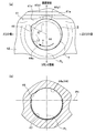
ここで、図4(a)に示すように、ピン孔44を軸方向に見て、内周面44aをピストン4の軸線PL方向とこの軸線PLに垂直な方向とで4等分したときに、連通溝46は、内周面44aのうち燃焼室32側且つスラスト側の範囲に形成されている。そして、内周面44aのうち、他の3つの範囲には、ピン孔44の軸線方向の溝は形成されておらず、滑らかな真円の円弧形状となっている。
なお、ピストン4の軸線PLは、シリンダ21の軸線CL(図1参照)と基本的に一致するが、シリンダ21内でピストン4が傾くことによって両者がずれることもある。
ここで、図4(a)に示すように、ピン孔44を軸方向に見て、内周面44aをピストン4の軸線PL方向とこの軸線PLに垂直な方向とで4等分したときに、連通溝46は、内周面44aのうち燃焼室32側且つスラスト側の範囲に形成されている。そして、内周面44aのうち、他の3つの範囲には、ピン孔44の軸線方向の溝は形成されておらず、滑らかな真円の円弧形状となっている。
なお、ピストン4の軸線PLは、シリンダ21の軸線CL(図1参照)と基本的に一致するが、シリンダ21内でピストン4が傾くことによって両者がずれることもある。
連通溝46は、ピン孔44の軸心と連通溝46の周方向の中心位置とを結ぶ直線L1と、ピン孔44の軸心を通りピストン4の軸線PLに直交する直線L2との成す角度θ(以下、「連通溝中心角度θ」という)が、20~23°の範囲となるように設けられるのが好ましい。これについては図10を参照して後に詳しく説明する。
凹溝47は、ピン孔44の内部に入り込んだオイルを周方向に移動し易くするための溝である。凹溝47は、図4(b)に示すように、内周面44aのうち、連通溝46よりも(より詳しくは、連通溝46の下側の端部を含み軸線PLに直交する平面P1よりも)クランク室22側の範囲のみに形成されている。凹溝47の両端部は、連通溝46につながっている。これにより、連通溝46と凹溝47の間のオイルの移動がスムーズになる。
ピン孔44の内周面44aの上部44a1は、図5に示すように、ピストン本体部41の下面41dに設けられた円弧状の凹部41d1と、段差なく滑らかに連続している。つまり、ピン孔44の開口部周縁には、ピン孔44の軸線に対して約45°傾いたテーパ面44bが設けられているが、ピン孔44の内周面の上部44a1付近だけは、このテーパ面44bが削られて(省略されて)なだらかに形成されている。これにより、リング溝41cに装着されたオイルリング(図示省略)で掻き落とされたオイルが、凹部41d1を伝ってピン孔44や連通溝46の内部に入り込み易くなる。
なお、ピストン本体部41の下面41d及び凹部41d1は、ピン孔44に向かってオイルが流れ易いように、ピンボス部42に近づくほど下方に位置するように傾斜している。
なお、ピストン本体部41の下面41d及び凹部41d1は、ピン孔44に向かってオイルが流れ易いように、ピンボス部42に近づくほど下方に位置するように傾斜している。
ちなみに、ピン孔44の内周面44aの上部44a1は、図5の方向視で直線状に形成されている。また、円弧状の凹部41d1も、図5の方向視で直線状に形成されている。内周面44aの上部44a1と円弧状の凹部41d1とは、ピン孔44の開口部(テーパ面44bの真上)で屈曲して連なっている。
ピストンピン7は、図1、図4に示すように、ピン孔44の内部に挿入されて、コンロッド6とピストン4とを連結する部材である。ピストンピン7は、ピン孔44よりも若干小径に形成されており、ピン孔44の内周面44aとピストンピン7との間にはオイルを溜めるための隙間Sが設けられている。ピストンピン7は、クランクシャフト5の回転に伴って、ピン孔44の内周面44aに沿って時計回り(クランクシャフト5の回転方向と同一方向)に旋回(図4の矢印x参照)する。
本実施形態に係る内燃機関1のピストン構造は、以上のように構成されるものであり、次に、図6乃至図10を参照してその動作及び作用効果について説明する。なお、図6乃至図8においては、オイルの軌跡をドット状のハッチングで示している。
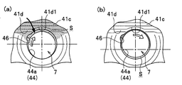
図6は、実施例1におけるピン孔内のピストンピン及びオイルの状態を説明する模式図であり、(a)はピストンピンがクランク室側にある状態、(b)はピストンピンが燃焼室側にある状態、をそれぞれ示している。
図6(a)に示すように、実施例1のピン孔44は、内周面44aのうち燃焼室32側且つスラスト側の範囲のみに、連通溝46を有している。
図6(a)に示すように、実施例1のピン孔44は、内周面44aのうち燃焼室32側且つスラスト側の範囲のみに、連通溝46を有している。
図6(a)に示すように、ピン孔44内において、ピストンピン7がクランク室22側にある場合、ピストンピン7の上側に隙間Sが形成される。また、シリンダ21の内壁に付着したオイルが、リング溝41cに装着されたオイルリング(図示省略)によって掻き落とされ、ピストン本体部41の下面41dを伝って、隙間S及び連通溝46に流入する。隙間Sのうち連通溝46が設けられた部分は、他の部分に比較して隙間Sの幅寸法が大きいので、オイルがピン孔44の軸方向に拡散しやすい。これにより、連通溝46に流入したオイルをピン孔44の軸方向に(中空部45側に)十分に供給することができる。
図6(b)に示すように、ピストンピン7が、クランクシャフト5及びコンロッド6の動作により、ピン孔44のスラスト側の内周面44aに沿って時計回りに旋回及び上昇すると、ピストンピン7の上側の隙間Sの幅寸法が徐々に狭くなり、オイルが反スラスト側に押し出される。このとき、ピン孔44の内周面44aのうち、燃焼室32側且つ反スラスト側の部分には連通溝46が形成されていないので、オイルがピン孔44から排出され難い。そのため、ピン孔44の内周面44aとピストンピン7との間の隙間Sにオイルが好適に保持され、両者の衝突音が抑制される。また、ピン孔44の内周面44aとピストンピン7との衝突が抑制されることにより、シリンダ21内におけるピストン4の挙動が安定し、シリンダ21の内壁とピストン4との衝突も抑制される。
つまり、実施例1のピン孔44によれば、ピン孔44の内周面44aとピストンピン7との間に保持されるオイルの量が増加する(排出されるオイルの量が減少する)ので、このオイルによって形成される油膜によりピン孔44の内周面44aとピストンピン7との打音が抑制されるのである。
つまり、実施例1のピン孔44によれば、ピン孔44の内周面44aとピストンピン7との間に保持されるオイルの量が増加する(排出されるオイルの量が減少する)ので、このオイルによって形成される油膜によりピン孔44の内周面44aとピストンピン7との打音が抑制されるのである。
また、ピストンピン7によって反スラスト側に押し出されたオイルは、ピン孔44の内周面44aのうち連通溝46よりもクランク室22側の部分に周方向に形成された凹溝47に沿って、ピン孔44の下方に移動する。これにより、ピン孔44のクランク室22側にもオイルを十分に供給することができる。なお、ピン孔44の内周面44aのうち、連通溝46よりも燃焼室32側の部分には、周方向の凹溝47が設けられていないので、オイルが周方向に流れ難くなり、オイルの流速を低下させて潤滑性を保持することができる。
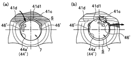
図7は、比較例1におけるピン孔内のピストンピン及びオイルの状態を説明する模式図であり、(a)はピストンピンがクランク室側にある状態、(b)はピストンピンが燃焼室側にある状態、をそれぞれ示している。
図7(a)に示すように、比較例1のピン孔44’は、内周面44a’のうち燃焼室32側且つスラスト側の範囲と、燃焼室32側且つ反スラスト側の範囲に、一対の連通溝46’,46’を有している。
図7(a)に示すように、比較例1のピン孔44’は、内周面44a’のうち燃焼室32側且つスラスト側の範囲と、燃焼室32側且つ反スラスト側の範囲に、一対の連通溝46’,46’を有している。
比較例1のピン孔44’では、図7(b)に示すように、ピストンピン7が時計回りに旋回及び上昇すると、隙間S内のオイルが反スラスト側に移動し、燃焼室32側且つ反スラスト側に設けられた連通溝46’からオイルが排出されてしまう。そのため、隙間Sに保持されるオイルの量が少なくなり、前記した実施例1に比較して、ピン孔44’とピストンピン7との衝突音の抑制効果が低下する。
図8は、比較例2におけるピン孔内のピストンピン及びオイルの状態を説明する模式図であり、(a)はピストンピンがクランク室側にある状態、(b)はピストンピンが燃焼室側にある状態、をそれぞれ示している。
図8(a)に示すように、比較例2のピン孔44”は、内周面44a”のうち燃焼室32側且つ反スラスト側の範囲のみに、連通溝46”を有している。比較例2のピン孔44”は、燃焼室32側且つスラスト側に連通溝46”を有していないので、前記した実施例1に比較して、ピン孔44”の軸方向へのオイル供給能力が低下する。
図8(a)に示すように、比較例2のピン孔44”は、内周面44a”のうち燃焼室32側且つ反スラスト側の範囲のみに、連通溝46”を有している。比較例2のピン孔44”は、燃焼室32側且つスラスト側に連通溝46”を有していないので、前記した実施例1に比較して、ピン孔44”の軸方向へのオイル供給能力が低下する。
また、比較例2のピン孔44”では、図8(b)に示すように、ピストンピン7が時計回りに旋回及び上昇すると、隙間S内のオイルが反スラスト側に移動し、燃焼室32側且つ反スラスト側に設けられた連通溝46”からオイルが排出されてしまう。そのため、隙間Sに保持されるオイルの量がさらに少なくなり、前記した実施例1及び比較例1に比較して、ピン孔44”とピストンピン7との衝突音の抑制効果がさらに低下する。
図9は、クランク角度とピン孔内のオイルの流体速度との相関関係を示すグラフである。なお、オイルの流体速度とは、隙間S内におけるオイルの移動速度を示す数値であり、公知の解析プログラムによって算出した値である。流体速度が小さいほど、隙間S内でのオイルの移動速度が遅くなり、隙間S内にオイルが好適に保持されることを示す。
図9に示すように、各グラフのピーク値を比較すると、従来構造である比較例1(破線参照)に対して、実施例1(太実線参照)では、オイルの流体速度が1/2以下に低下している。これにより、実施例1では、比較例1に比較してピン孔44とピストンピン7の隙間Sにオイルを好適に保持できることが分かる。その結果、実施例1では、ピン孔44の内周面44aとピストンピン7の隙間Sに保持されたオイルによって、両者の衝突による打音の発生を抑制することができる。
一方、比較例2(細実線参照)では、比較例1に対してオイルの流体速度がほぼ2倍に上昇している。そのため、反スラスト側のみに連通溝46を設けた場合には、隙間Sにオイルを好適に保持できず、ピン孔44とピストンピン7とが衝突し易くなる。このことから、連通溝46を形成する位置は、ピストン4に作用するスラスト力の方向やピストンピン7の旋回方向を考慮して適切に設定する必要があることが分かる。
図10は、連通溝中心角度θと流体速度との相関関係を示すグラフである。実施例1(太破線参照)は、オフセット距離L(図1参照)を14mmとした場合である。実施例2(太実線参照)は、オフセット距離L(図1参照)を0mmとした場合である。
図10に示すように、オフセット距離Lを14mmとした実施例1では、連通溝中心角度θを約15°~30°の範囲で変化させると、θ=約23°のときに、流体速度が最も小さくなることが分かった。また、オフセット距離Lを0mmとした実施例2では、θ=約20°のときに、流体速度が最も小さくなることが分かった。このことから、オフセット距離Lが大きいほど、連通溝46を燃焼室32側に設けるようにすれば、オイルの流速を低下させて、ピン孔44の内周面44aとピストンピン7との打音を抑制することができることが分かる。
以上、本発明の実施形態について図面を参照して詳細に説明したが、本発明はこれに限定されるものではなく、発明の主旨を逸脱しない範囲で適宜変更可能である。
例えば、本実施形態では、シリンダ21の軸線CLを、クランクシャフト5の軸心5aから反スラスト側に所定距離Lだけオフセット(いわゆる正オフセット)した場合を例にとって説明したが、本発明はこれに限定されるものではなく、オフセット距離Lを0としてもよいし、スラスト側に所定距離Lだけオフセット(いわゆる逆オフセット)してもよい。
ちなみに、実験の結果、オフセット距離Lを0とした場合及び逆オフセットにした場合のいずれでも、クランクシャフト5を図1に示す時計回り方向(矢印y参照)に回転させれば、ピストンピン7は、ピン孔44の内部で図4(a)に示す時計回り方向(矢印x参照)に旋回することが判明した。よって、連通溝46は本実施形態と同様に、燃焼室32側且つスラスト側に設ければよい。
また、本実施形態では、ピストン本体部41の下面41dのうちピン孔44に対応する部分に、凹部41d1を形成したが、本発明はこれに限定されるものではなく、凹部41d1を省略して、ピン孔44の内周面44aの上部44a1とピストン本体部41の下面41dとが直接滑らかに連続する構成としてもよい。
また、本実施形態では、ピストンピン7の固定構造について、いわゆるセミフローティング方式を採用した場合を例にとって説明したが、本発明はこれに限定されるものではなく、例えば、ピストンピン7の両端にクリップ(Cリング)を取り付けて、ピン孔44に対してピストンピン7を浮かした状態に保持するいわゆるフルフローティング方式のピストン構造などに採用してもよい。
また、本実施形態では、ピン孔44の内周面44aに、周方向に沿って凹溝47を設けたが、本発明はこれに限定されるものではなく、例えば、凹溝47を省略してもよい。
また、本実施形態では、直列形式の内燃機関1に本発明を適用した場合を例にとって説明したが、本発明はこれに限定されるものではなく、V型エンジンなど、他の形式の内燃機関に本発明を適用してもよい。
1 内燃機関
2 シリンダブロック
21 シリンダ
22 クランク室
3 シリンダヘッド
32 燃焼室
4 ピストン
41 ピストン本体部
41c リング溝
41d 下面
42 ピンボス部
43 スカート部
44 ピン孔
44a 内周面
46 連通溝
47 凹溝
5 クランクシャフト
6 コンロッド
7 ピストンピン
S 隙間
2 シリンダブロック
21 シリンダ
22 クランク室
3 シリンダヘッド
32 燃焼室
4 ピストン
41 ピストン本体部
41c リング溝
41d 下面
42 ピンボス部
43 スカート部
44 ピン孔
44a 内周面
46 連通溝
47 凹溝
5 クランクシャフト
6 コンロッド
7 ピストンピン
S 隙間
Claims (9)
- ピストンに形成したピン孔にピストンピンを挿通してなる内燃機関のピストン構造であって、
前記ピン孔の内周面には前記ピストンの内外を連通する連通溝が設けられ、
前記連通溝は、前記ピン孔の内周面のうち、前記ピストンの燃焼室側且つスラスト側の範囲のみに設けられていることを特徴とする内燃機関のピストン構造。 - 前記連通溝は、シリンダ軸線に対するクランク軸回動中心のオフセット量が増えるほど、燃焼室側に偏倚して設けられることを特徴とする請求の範囲第1項に記載の内燃機関のピストン構造。
- 前記連通溝は、前記ピン孔の軸心と前記連通溝の周方向の中心位置とを結ぶ直線と、前記ピン孔の軸心を通りピストン軸線に直交する直線との成す角度が20°以上23°以下となるように設けられていることを特徴とする請求の範囲第1項に記載の内燃機関のピストン構造。
- 前記連通溝は、前記ピン孔の軸心と前記連通溝の周方向の中心位置とを結ぶ直線と、前記ピン孔の軸心を通りピストン軸線に直交する直線との成す角度が20°以上23°以下となるように設けられていることを特徴とする請求の範囲第2項に記載の内燃機関のピストン構造。
- 前記ピストンは、外周面にリング溝が形成されたピストン本体部と、前記ピストン本体部の下面から下方に延出すると共に前記ピン孔が形成された一対のピンボス部と、を有し、
前記ピストン本体部の下面と前記ピン孔の内周面の上部とは、段差なく連続していることを特徴とする請求の範囲第1項に記載の内燃機関のピストン構造。 - 前記ピストンは、外周面にリング溝が形成されたピストン本体部と、前記ピストン本体部の下面から下方に延出すると共に前記ピン孔が形成された一対のピンボス部と、を有し、
前記ピストン本体部の下面と前記ピン孔の内周面の上部とは、段差なく連続していることを特徴とする請求の範囲第2項に記載の内燃機関のピストン構造。 - 前記ピストンは、外周面にリング溝が形成されたピストン本体部と、前記ピストン本体部の下面から下方に延出すると共に前記ピン孔が形成された一対のピンボス部と、を有し、
前記ピストン本体部の下面と前記ピン孔の内周面の上部とは、段差なく連続していることを特徴とする請求の範囲第3項に記載の内燃機関のピストン構造。 - 前記ピストンは、外周面にリング溝が形成されたピストン本体部と、前記ピストン本体部の下面から下方に延出すると共に前記ピン孔が形成された一対のピンボス部と、を有し、
前記ピストン本体部の下面と前記ピン孔の内周面の上部とは、段差なく連続していることを特徴とする請求の範囲第4項に記載の内燃機関のピストン構造。 - 前記ピン孔の内周面には周方向に凹溝が形成され、
前記凹溝は、前記連通溝につながり、かつ、前記連通溝よりもクランク室側の範囲のみに形成されていることを特徴とする請求の範囲第1項から第8項のいずれか1項に記載の内燃機関のピストン構造。
Applications Claiming Priority (2)
| Application Number | Priority Date | Filing Date | Title |
|---|---|---|---|
| JP2011172856 | 2011-08-08 | ||
| JP2011-172856 | 2011-08-08 |
Publications (1)
| Publication Number | Publication Date |
|---|---|
| WO2013021789A1 true WO2013021789A1 (ja) | 2013-02-14 |
Family
ID=47668306
Family Applications (1)
| Application Number | Title | Priority Date | Filing Date |
|---|---|---|---|
| PCT/JP2012/068149 Ceased WO2013021789A1 (ja) | 2011-08-08 | 2012-07-18 | 内燃機関のピストン構造 |
Country Status (2)
| Country | Link |
|---|---|
| JP (1) | JPWO2013021789A1 (ja) |
| WO (1) | WO2013021789A1 (ja) |
Cited By (1)
| Publication number | Priority date | Publication date | Assignee | Title |
|---|---|---|---|---|
| KR102159566B1 (ko) * | 2020-07-30 | 2020-09-24 | 정문식 | 유분상승 및 회전부하를 방지하는 피스톤 |
Citations (3)
| Publication number | Priority date | Publication date | Assignee | Title |
|---|---|---|---|---|
| JPH09100745A (ja) * | 1995-10-05 | 1997-04-15 | Unisia Jecs Corp | 内燃機関用ピストン |
| JP2000240508A (ja) * | 1999-02-22 | 2000-09-05 | Honda Motor Co Ltd | ピストンのピン孔構造 |
| JP2004225597A (ja) * | 2003-01-22 | 2004-08-12 | Toyota Motor Corp | 内燃機関用ピストン |
-
2012
- 2012-07-18 WO PCT/JP2012/068149 patent/WO2013021789A1/ja not_active Ceased
- 2012-07-18 JP JP2013527944A patent/JPWO2013021789A1/ja not_active Ceased
Patent Citations (3)
| Publication number | Priority date | Publication date | Assignee | Title |
|---|---|---|---|---|
| JPH09100745A (ja) * | 1995-10-05 | 1997-04-15 | Unisia Jecs Corp | 内燃機関用ピストン |
| JP2000240508A (ja) * | 1999-02-22 | 2000-09-05 | Honda Motor Co Ltd | ピストンのピン孔構造 |
| JP2004225597A (ja) * | 2003-01-22 | 2004-08-12 | Toyota Motor Corp | 内燃機関用ピストン |
Cited By (1)
| Publication number | Priority date | Publication date | Assignee | Title |
|---|---|---|---|---|
| KR102159566B1 (ko) * | 2020-07-30 | 2020-09-24 | 정문식 | 유분상승 및 회전부하를 방지하는 피스톤 |
Also Published As
| Publication number | Publication date |
|---|---|
| JPWO2013021789A1 (ja) | 2015-03-05 |
Similar Documents
| Publication | Publication Date | Title |
|---|---|---|
| CN112955633B (zh) | 具有被成形用于限制阀凹陷的双冠状座表面的用于发动机的阀座插入件 | |
| CN112392568B (zh) | 用于长寿命天然气贫燃发动机的阀座插入件 | |
| EP2045488B1 (en) | Piston ring of reciprocating engine | |
| US7854191B2 (en) | Three-piece oil ring and combination of the three-piece oil ring and piston | |
| CN101069007B (zh) | 内燃机用发动机的活塞及内燃机用发动机的活塞和活塞环的组合 | |
| US8763575B2 (en) | Valve train mechanism of internal combustion engine | |
| JP2011080436A (ja) | ピストン | |
| US8985081B2 (en) | Engine valve device | |
| CN108868961B (zh) | 一种曲轴箱强制通风阀 | |
| JPH08177426A (ja) | 内燃機関の動弁装置 | |
| JP2009281387A (ja) | 内燃機関用エンジンのピストン及び内燃機関用エンジンのピストンとピストンリングの組合せ | |
| WO2013021789A1 (ja) | 内燃機関のピストン構造 | |
| US9068530B2 (en) | Connecting rod with lubrication passage | |
| JP2011038414A (ja) | 内燃機関用ピストン | |
| US20080110332A1 (en) | Oil supply structure for reducing friction of cam shaft | |
| JP6296048B2 (ja) | 内燃機関の動弁装置 | |
| JP2016044794A (ja) | ピストンリング付ピストン及び内燃機関 | |
| JP6206191B2 (ja) | 内燃機関のピストン | |
| JP2021017829A (ja) | バルブ構造および内燃機関 | |
| JP6374269B2 (ja) | ピストンピンの潤滑構造 | |
| JP2021050636A (ja) | バルブ構造および内燃機関 | |
| JP2017218933A (ja) | ピストンピンの潤滑構造 | |
| JP2021017825A (ja) | バルブ構造および内燃機関 | |
| JP2018054041A (ja) | コンロッドのブッシュ | |
| KR102384112B1 (ko) | 내연기관용 스틸 피스톤 |
Legal Events
| Date | Code | Title | Description |
|---|---|---|---|
| 121 | Ep: the epo has been informed by wipo that ep was designated in this application |
Ref document number: 12821454 Country of ref document: EP Kind code of ref document: A1 |
|
| ENP | Entry into the national phase |
Ref document number: 2013527944 Country of ref document: JP Kind code of ref document: A |
|
| NENP | Non-entry into the national phase |
Ref country code: DE |
|
| 122 | Ep: pct application non-entry in european phase |
Ref document number: 12821454 Country of ref document: EP Kind code of ref document: A1 |