WO2013005352A1 - 電流検出装置および電力量計 - Google Patents
電流検出装置および電力量計 Download PDFInfo
- Publication number
- WO2013005352A1 WO2013005352A1 PCT/JP2011/077958 JP2011077958W WO2013005352A1 WO 2013005352 A1 WO2013005352 A1 WO 2013005352A1 JP 2011077958 W JP2011077958 W JP 2011077958W WO 2013005352 A1 WO2013005352 A1 WO 2013005352A1
- Authority
- WO
- WIPO (PCT)
- Prior art keywords
- coil
- coils
- detection device
- current detection
- magnetic body
- Prior art date
Links
- 230000005611 electricity Effects 0.000 title 1
- 239000004020 conductor Substances 0.000 claims abstract description 42
- 238000001514 detection method Methods 0.000 claims description 71
- 238000010586 diagram Methods 0.000 description 16
- 239000011162 core material Substances 0.000 description 9
- 238000004519 manufacturing process Methods 0.000 description 5
- 239000000696 magnetic material Substances 0.000 description 4
- 238000004804 winding Methods 0.000 description 4
- 238000012986 modification Methods 0.000 description 3
- 230000004048 modification Effects 0.000 description 3
- XEEYBQQBJWHFJM-UHFFFAOYSA-N Iron Chemical compound [Fe] XEEYBQQBJWHFJM-UHFFFAOYSA-N 0.000 description 2
- 239000000853 adhesive Substances 0.000 description 2
- 230000001070 adhesive effect Effects 0.000 description 2
- 238000006243 chemical reaction Methods 0.000 description 2
- 210000003298 dental enamel Anatomy 0.000 description 2
- 239000000463 material Substances 0.000 description 2
- 238000005259 measurement Methods 0.000 description 2
- 229910000889 permalloy Inorganic materials 0.000 description 2
- 229920001707 polybutylene terephthalate Polymers 0.000 description 2
- 239000011347 resin Substances 0.000 description 2
- 229920005989 resin Polymers 0.000 description 2
- 229910000859 α-Fe Inorganic materials 0.000 description 2
- RYGMFSIKBFXOCR-UHFFFAOYSA-N Copper Chemical compound [Cu] RYGMFSIKBFXOCR-UHFFFAOYSA-N 0.000 description 1
- ISWSIDIOOBJBQZ-UHFFFAOYSA-N Phenol Chemical compound OC1=CC=CC=C1 ISWSIDIOOBJBQZ-UHFFFAOYSA-N 0.000 description 1
- 239000007767 bonding agent Substances 0.000 description 1
- 229910052802 copper Inorganic materials 0.000 description 1
- 239000010949 copper Substances 0.000 description 1
- 230000000694 effects Effects 0.000 description 1
- 230000004927 fusion Effects 0.000 description 1
- 229910052742 iron Inorganic materials 0.000 description 1
- 239000004973 liquid crystal related substance Substances 0.000 description 1
- 239000002184 metal Substances 0.000 description 1
- 229910052751 metal Inorganic materials 0.000 description 1
- -1 polybutylene terephthalate Polymers 0.000 description 1
Images


Classifications
-
- G—PHYSICS
- G01—MEASURING; TESTING
- G01R—MEASURING ELECTRIC VARIABLES; MEASURING MAGNETIC VARIABLES
- G01R19/00—Arrangements for measuring currents or voltages or for indicating presence or sign thereof
-
- G—PHYSICS
- G01—MEASURING; TESTING
- G01R—MEASURING ELECTRIC VARIABLES; MEASURING MAGNETIC VARIABLES
- G01R15/00—Details of measuring arrangements of the types provided for in groups G01R17/00 - G01R29/00, G01R33/00 - G01R33/26 or G01R35/00
- G01R15/14—Adaptations providing voltage or current isolation, e.g. for high-voltage or high-current networks
- G01R15/18—Adaptations providing voltage or current isolation, e.g. for high-voltage or high-current networks using inductive devices, e.g. transformers
- G01R15/181—Adaptations providing voltage or current isolation, e.g. for high-voltage or high-current networks using inductive devices, e.g. transformers using coils without a magnetic core, e.g. Rogowski coils
-
- G—PHYSICS
- G01—MEASURING; TESTING
- G01R—MEASURING ELECTRIC VARIABLES; MEASURING MAGNETIC VARIABLES
- G01R15/00—Details of measuring arrangements of the types provided for in groups G01R17/00 - G01R29/00, G01R33/00 - G01R33/26 or G01R35/00
- G01R15/14—Adaptations providing voltage or current isolation, e.g. for high-voltage or high-current networks
- G01R15/18—Adaptations providing voltage or current isolation, e.g. for high-voltage or high-current networks using inductive devices, e.g. transformers
- G01R15/186—Adaptations providing voltage or current isolation, e.g. for high-voltage or high-current networks using inductive devices, e.g. transformers using current transformers with a core consisting of two or more parts, e.g. clamp-on type
-
- H—ELECTRICITY
- H01—ELECTRIC ELEMENTS
- H01F—MAGNETS; INDUCTANCES; TRANSFORMERS; SELECTION OF MATERIALS FOR THEIR MAGNETIC PROPERTIES
- H01F38/00—Adaptations of transformers or inductances for specific applications or functions
- H01F38/20—Instruments transformers
- H01F38/22—Instruments transformers for single phase ac
- H01F38/28—Current transformers
- H01F38/30—Constructions
Definitions
- the present invention relates to a current detection device for detecting the magnitude of a current flowing through a conductor by magnetoelectric conversion and a watt hour meter using the same.
- the current detection device for detecting a load current in a general home, factory, office, or the like.
- the current detection device includes, for example, a primary conductor that generates a magnetic field when a load current flows, and a magnetoelectric conversion unit that detects the magnetic field generated by the primary conductor (see, for example, Patent Document 1).
- the magnetoelectric converter is formed by a coil in which a conducting wire such as an enamel wire is wound around a toroidal magnetic core called a toroidal core.
- a conducting wire such as an enamel wire
- a toroidal magnetic core called a toroidal core
- Patent Document 2 discloses a plurality of coil portions that detect a magnetic field generated in the primary conductor 11 around a primary conductor that generates a magnetic field that is directly proportional to a measurement current, and a plurality of these coils.
- a support section made of a magnetic material is provided in which a plurality of coil sections are connected by wiring so as to be magnetically in series, and is generated in the plurality of coil sections based on the magnetic field generated by the primary conductor.
- a current detection device that outputs an electrical signal from an output terminal via a wiring is disclosed.
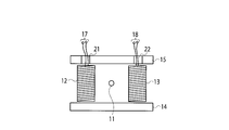
- FIG. 1 is a schematic diagram showing a configuration of a conventional general current detection device as disclosed in Patent Document 2.
- the current detection device includes a first coil 12 and a second coil 13 that detect the magnetic field generated in the primary conductor 11 around the primary conductor 11 that generates a magnetic field according to the magnitude of the measurement current, A first magnetic body 14 and a second magnetic body 15 for supporting the first coil 12 and the second coil 13 and magnetically short-circuiting them are provided, and the first coil 12 is configured based on the magnetic field generated by the primary conductor 11.
- the generated electrical signal is output from the output terminal 17 via the wiring, and the electrical signal generated by the second coil 13 is output from the output terminal 18 via the wiring.
- the above-described conventional current detection device has a structure that requires the wiring from the first coil 12 to the output terminal 17 and the second coil 13 to the output terminal 18, so that the manufacturability is improved by the work for routing the wiring. There is a problem that the cost is increased.
- An object of the present invention is to provide an inexpensive current detection device and watt hour meter that are excellent in manufacturability.
- a current detection device is configured to face a conductor through which a current to be measured flows, a plurality of coils arranged around the conductor, and one end face of the plurality of coils.
- a first magnetic body which is provided and magnetically short-circuits the plurality of coils, and is provided so as to face the other end face of the plurality of coils and magnetically short-circuits the plurality of coils, and from the plurality of coils.
- the through-hole which lets a coil wiring pass is provided with the 2nd magnetic body each provided in the position which opposes the other end surface of several coils.
- the watt hour meter according to the present invention includes the above-described current detection device, a voltage detection unit that detects a voltage generated in the conductor, a current detected by the current detection device, and a voltage detected by the voltage detection unit.
- a power calculation unit that calculates the amount of power based on
- FIG. 1 is a diagram for explaining a conventional current detection device.
- FIG. 2 is a schematic diagram illustrating a configuration of the current detection device according to the first embodiment of the present invention.
- FIG. 3 is a schematic diagram showing a configuration of a current detection device according to Embodiment 2 of the present invention.
- FIG. 4 is a schematic diagram showing the configuration of a current detection device according to Embodiment 3 of the present invention and its modification.
- FIG. 5 is a schematic diagram showing the configuration of a current detection device according to Embodiment 4 of the present invention.
- FIG. 6 is a block diagram showing a configuration of a watt-hour meter according to Embodiment 5 of the present invention.
- FIG. 2 is a schematic diagram illustrating a configuration of the current detection device according to the first embodiment of the present invention.
- the current detection device includes a linear primary conductor 11 and a first coil 12, a second coil 13, a first magnetic body 14, and a second magnetic body 15 disposed around the primary conductor 11.
- the primary conductor 11 corresponds to the “conductor” of the present invention and is made of a conductive metal such as iron or copper.
- the primary conductor 11 generates a magnetic field when a load current that is a current to be measured flows.
- the first coil 12 and the second coil 13 correspond to the “plural coils” of the present invention, and are configured by winding a conductive wire such as an enamel wire around a non-conductive core material such as phenol or bake. Yes. An electromotive force is induced in each of the first coil 12 and the second coil 13 according to the current flowing through the primary conductor 11 and is output as an electric signal.
- the 1st coil 12 and the 2nd coil 13 may have a hollow core material, and may have the core material filled with the material to the inside. Further, a magnetic material such as ferrite or permalloy may be used as a core material. Furthermore, the first coil 12 and the second coil 13 may not be provided with a core material, and may be formed by joining coil conductors with a bonding agent such as a fusion material or an adhesive.
- the first magnetic body 14 and the second magnetic body 15 are made of ferrite, permalloy, or the like, and are arranged at positions where the first coil 12 and the second coil 13 are sandwiched.
- the first magnetic body 14 is provided so as to face one end face (the lower end face in FIG. 1) of the first coil 12 and the second coil 13. And the second coil 13 are magnetically short-circuited.
- the second magnetic body 15 is provided so as to face the other end surfaces (the upper end surface in FIG. 1) of the first coil 12 and the second coil 13, and the first coil 12 and the second coil 13 are magnetized. Short circuit.
- a through hole 21 for guiding the coil wiring from the first coil 12 to the output terminal 17 is provided at a predetermined position of the second magnetic body 15, specifically, at a position facing the other end face of the first coil 12.
- a through hole 22 for guiding the coil wiring from the second coil 13 to the output terminal 18 is provided at a position facing the other end face of the second coil 13.
- the output terminal 17 outputs an electrical signal generated by the first coil 12 in accordance with the current flowing through the primary conductor 11.
- the output terminal 18 outputs an electrical signal generated by the second coil 13 according to the current flowing through the primary conductor 11.
- the first coil 12 and the second coil 13 receive a magnetic field generated by a current flowing through the primary conductor 11, and generate an electrical signal corresponding to the current in the coil conductor.
- the coil conductor of the first coil 12 is connected to the output terminal 17, and an electrical signal corresponding to the current flowing through the primary conductor 11 is output to the output terminal 17.
- the coil conductor of the second coil 13 is connected to the output terminal 18, and an electrical signal corresponding to the current flowing through the primary conductor 11 is output to the output terminal 18.
- the electric signals output to these output terminals 17 and 18 represent the magnitude of the current flowing through the primary conductor 11.
- the connection between the first coil 12 and the second coil 13 and the first magnetic body 14 and the second magnetic body 15 is the first magnetic body 14 and the second magnetic body.
- a recess may be formed in the body 15, and the first coil 12 and the second coil 13 may be fitted into the recess.
- the first coil 12 and the second coil 13 may be structured to be fixed to the first magnetic body 14 and the second magnetic body 15 with an adhesive or the like. Furthermore, the first coil 12 and the second coil 13, and the first magnetic body 14 and the second magnetic body 15 do not need to be in contact with each other, and are fixed by mounting them on a resin case or the like. It is good.
- the through holes 21 and 22 for passing the coil wiring are formed in the second magnetic body 15, and the first coil 12 and the second coil are formed. Since the coil lead wires from 13 are connected to the output terminals 17 and 18 through the through holes 21 and 22, respectively, the operation of routing the wiring becomes easy, and the labor for manufacturing can be reduced. . As a result, the productivity can be improved and the cost can be reduced.
- FIG. 3 is a schematic diagram illustrating the configuration of the current detection device according to the second embodiment of the present invention.
- This current detection device is the same as the current detection device according to the first embodiment except that the structure of the second magnetic body 15 of the current detection device according to the first embodiment is changed to be a second magnetic body 15a. is there. Below, it demonstrates centering on the part different from the electric current detection apparatus which concerns on Example 1.
- FIG. 1 illustrates that the structure of the second magnetic body 15 of the current detection device according to the first embodiment is changed to be a second magnetic body 15a. is there. Below, it demonstrates centering on the part different from the electric current detection apparatus which concerns on Example 1.
- the second magnetic body 15a is provided so as to face the other end face (the upper end face in FIG. 3) of the first coil 12 and the second coil 13, and the first coil 12 and the second coil 13 are magnetized. Short circuit.
- a predetermined position of the second magnetic body 15a specifically, a position other than a position facing the other end face of the first coil 12, and a position other than a position facing the other end face of the second coil 13.
- one through hole 23 for passing the coil wiring is formed in the second magnetic body 15a, and the coil conductors from the first coil 12 and the second coil 13 are connected. Since it is configured to be connected to the output terminals 17 and 18 through the through hole 23, the work of routing the wiring becomes easy, and the labor for manufacturing can be reduced, and as a result, the productivity can be improved. In addition, the cost can be reduced.
- the through hole 23 through which the coil wiring from the first coil 12 and the second coil 13 passes is provided at a position other than the position facing the other end face of the first coil 12 and the second coil 13,
- the other ends of the first coil 12 and the second coil 13 are covered with a magnetic material, and the disturbance resistance performance can be improved.
- the number of the through holes 23 formed in the second magnetic body 15a is only one, but the position is not a position opposite to the other end surface of the first coil 12. And if it is a position other than the position which opposes the other end surface of the 2nd coil 13, a some through-hole can also be provided.
- FIG. 4A is a schematic diagram illustrating a configuration of a current detection device according to Embodiment 3 of the present invention.
- This current detection device is changed to a structure in which the coil conductors of the first coil 12 and the second coil 13 of the current detection device according to the first embodiment are wound around a bobbin to be a first coil 12a and a second coil 13a. Except for this point, it is the same as the current detection device according to the first embodiment. Below, it demonstrates centering on the part different from the electric current detection apparatus which concerns on Example 1.
- the first coil 12a and the second coil 13a correspond to “a plurality of coils” of the present invention.
- the first coil 12 a is configured by a bobbin-wound coil in which a coil conductor is wound around a bobbin 31, and the winding start and end of the coil conductor are entangled with a pin terminal 24.
- the second coil 13 a is configured by a bobbin winding coil in which a coil conductor is wound around a bobbin 32, and the winding start and end of the coil conductor are entangled with the pin terminal 25.
- the bobbins 31 and 32 are made of, for example, PBT (polybutylene terephthalate) resin.
- the first coil 12a and the second coil 13a are bobbin-wound coils, so that it is not necessary to route the wiring, and the labor for manufacturing can be reduced. As a result, the productivity can be improved and the cost can be reduced.
- FIG. 4B is a schematic diagram illustrating a configuration of a current detection device according to a modification of the third embodiment of the present invention.
- the shapes of the flanges of the bobbins 31 and 32 included in the first coil 12a and the second coil 13a of the current detection device according to the third embodiment are changed to be bobbins 31a and 32a, and the first coil Except for the point that 12a and the 2nd coil 13a are the 1st coil 12b and the 2nd coil 13b, respectively, it is the same as the current detection device concerning Example 3. Below, it demonstrates centering on the part which is different from the electric current detection apparatus which concerns on Example 3.
- FIG. 4B is a schematic diagram illustrating a configuration of a current detection device according to a modification of the third embodiment of the present invention.
- the shapes of the flanges of the bobbins 31 and 32 included in the first coil 12a and the second coil 13a of the current detection device according to the third embodiment are changed to be bobbins 31a and 32a,
- the first coil 12b and the second coil 13b correspond to “a plurality of coils” of the present invention.
- the flange on the second magnetic body 15a side of the bobbin 31a of the first coil 12b is partially extended to a position facing the through hole 23 of the second magnetic body 15a, and the coil conductor of the first coil 12b is
- the flange 33 is connected to the output terminal 17 through the through hole 23 from the extended portion 33 of the flange.
- the flange on the second magnetic body 15a side of the bobbin 32a of the second coil 13b is partially extended to a position facing the through hole 23 of the second magnetic body 15a, and the coil conductor of the second coil 13b. Is connected to the output terminal 18 from the extended portion 34 of the flange through the through hole 23.
- the current detection device in addition to the effects of the current detection device according to the third embodiment, it is possible to further reduce the labor for manufacturing. As a result, the productivity can be improved and the cost can be reduced.
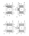
- FIG. 5 is a schematic diagram illustrating a configuration of a current detection device according to Embodiment 4 of the present invention.
- the first magnetic body and the second magnetic body of the current detection device according to the first to third embodiments are formed in the same shape. In the following, description will be made centering on differences from the current detection device according to the current detection device according to the first to third embodiments.
- FIG. 5A is a diagram in which the first magnetic body 14 of the current detection device according to the first embodiment is changed to a first magnetic body 14 a having the same shape as the second magnetic body 15.
- FIG. 5B is a diagram in which the first magnetic body 14 of the current detection device according to the second embodiment is changed to a first magnetic body 14b having the same shape as the second magnetic body 15a.
- FIG. 5C is a diagram in which the first magnetic body 14 of the current detection device according to the third embodiment is changed to a first magnetic body 14 a having the same shape as the second magnetic body 15.
- FIG. 5D shows a configuration in which the first magnetic body 14 of the current detection device according to the modification of the third embodiment is changed to a first magnetic body 14b having the same shape as the second magnetic body 15a.
- the first magnetic body and the second magnetic body can be used as a common part, so the types of parts can be reduced and the cost can be reduced. Down is possible.
- Example 4 of the present invention is a watt-hour meter using the current detection device according to Examples 1 to 4 described above.
- FIG. 6 is a block diagram illustrating the configuration of the watt-hour meter according to the fourth embodiment.
- This watt-hour meter includes a current detection device 51, a voltage detection unit 52, a power calculation unit 53, and a display unit 54.
- the current detection device 51 any of the current detection devices according to the first to fourth embodiments described above is used.
- the current detection device 51 detects a use current (A1) used at a consumer's load, converts it into an electrical signal corresponding to the use current, and outputs it.
- A1 use current
- the voltage detector 52 is a part for detecting the voltage of the system to be measured, and is constituted by a voltage dividing resistor such as a voltage transformer or an attenuator. It is detected, converted into a low level voltage signal that is directly proportional to the working voltage, and output.
- the power calculator 53 calculates the amount of power based on the current flowing in the conductor 11 detected by the current detector 51 and the voltage detected by the voltage detector 52.
- the power calculation unit 53 is configured by a digital multiplication circuit, a DSP (digital signal processor), and the like.
- the power calculation unit 53 receives a signal related to the current used (A1) output from the current detection device 51, and the voltage detection unit 52.
- the output signal regarding the used voltage (V1) is multiplied and converted to data (A1 ⁇ V1) that is directly proportional to the consumer's used power.
- the power calculation unit 53 edits and outputs the calculation result of data (A1 ⁇ V1) that is directly proportional to the power used as usage data.
- the usage data refers to data related to the power used by the customer, such as the total accumulated power used by the customer's load and the time zone usage for each time zone.
- the signal related to the used current (A1) output from the current detection device 51 is a signal that is directly proportional to the signal obtained by differentiating the used current (A1) except when the coil core is a magnetic material.
- the electric power calculation unit 53 integrates the data.
- the display unit 54 is configured by a liquid crystal display or the like, and displays usage data.
- the watt-hour meter according to the fifth embodiment of the present invention it is possible to realize a watt-hour meter having a current detection device that does not require time for manufacturing, has excellent manufacturability, and can reduce costs.
- the work of routing the wiring becomes easy, the productivity can be improved, and the cost can be reduced.
Landscapes
- Engineering & Computer Science (AREA)
- Power Engineering (AREA)
- Physics & Mathematics (AREA)
- General Physics & Mathematics (AREA)
- Measuring Instrument Details And Bridges, And Automatic Balancing Devices (AREA)
Abstract
Description
図2は、本発明の実施例1に係る電流検出装置の構成を示す概略図である。この電流検出装置は、線状の一次導体11と、この一次導体11の周囲に配置された第1コイル12、第2コイル13、第1磁性体14および第2磁性体15を備えている。
図3は、本発明の実施例2に係る電流検出装置の構成を示す概略図である。この電流検出装置は、実施例1に係る電流検出装置の第2磁性体15の構造が変更されて第2磁性体15aとされている点を除けば実施例1に係る電流検出装置と同じである。以下では、実施例1に係る電流検出装置と相違する部分を中心に説明する。
図4(a)は、本発明の実施例3に係る電流検出装置の構成を示す概略図である。この電流検出装置は、実施例1に係る電流検出装置の第1コイル12および第2コイル13のコイル導線がボビンに巻かれた構造に変更されて第1コイル12aおよび第2コイル13aとされている点を除けば実施例1に係る電流検出装置と同じである。以下では、実施例1に係る電流検出装置と相違する部分を中心に説明する。
図5は、本発明の実施例4に係る電流検出装置の構成を示す概略図である。この電流検出装置は、実施例1~実施例3に係る電流検出装置の第1磁性体および第2磁性体を同一形状にしたものである。以下では、実施例1~実施例3に係る電流検出装置に係る電流検出装置と相違する部分を中心に説明する。
本発明の実施例4は、上述した実施例1~実施例4に係る電流検出装置を利用した電力量計である。図6は、実施例4に係る電力量計の構成を示すブロック図である。この電力量計は、電流検出装置51、電圧検出部52、電力演算部53および表示部54を備えている。
Claims (5)
- 被測定電流が流れる導体と、
前記導体の周囲に配置された複数のコイルと、
前記複数のコイルの一方の端面に対向するように設けられて前記複数のコイルを磁気的に短絡する第1磁性体と、
前記複数のコイルの他方の端面に対向するように設けられて前記複数のコイルを磁気的に短絡し、且つ、前記複数のコイルからのコイル配線を通す貫通穴が前記複数のコイルの前記他方の端面に対向する位置にそれぞれ設けられた第2磁性体と、
を備える電流検出装置。 - 前記第2磁性体の前記貫通穴は、前記複数のコイルの他方の端面に対向する位置に代えて、前記複数のコイルの前記他方の端面に対向する位置以外の位置に設けられている請求項1記載の電流検出装置。
- 前記複数のコイルは、ボビン巻コイルから成る請求項1記載の電流検出装置。
- 前記第1磁性体は、前記第2磁性体と同一形状を有する請求項1記載の電流検出装置。
- 請求項1乃至請求項4のいずれか1項記載の電流検出装置と、
前記導体に発生する電圧を検出する電圧検出部と、
前記電流検出装置により検出された電流と、前記電圧検出部で検出された電圧とに基づき電力又は電力量を算出する電力演算部と、
を備える電力量計。
Priority Applications (7)
| Application Number | Priority Date | Filing Date | Title |
|---|---|---|---|
| AU2011372577A AU2011372577B2 (en) | 2011-07-01 | 2011-12-02 | Current detection device and electricity meter |
| US14/127,354 US9354258B2 (en) | 2011-07-01 | 2011-12-02 | Current detection device and electricity meter |
| CA2840021A CA2840021C (en) | 2011-07-01 | 2011-12-02 | Current detection device and electricity meter |
| CN201180071779.0A CN103620421B (zh) | 2011-07-01 | 2011-12-02 | 电流检测装置以及电量计 |
| BR112013033144A BR112013033144A2 (pt) | 2011-07-01 | 2011-12-02 | dispositivo de detecção de corrente e medidor de eletricidade |
| EP11868916.5A EP2728366B1 (en) | 2011-07-01 | 2011-12-02 | Current detector and electricity meter |
| HK14108641.0A HK1195363A1 (zh) | 2011-07-01 | 2014-08-25 | 電流檢測裝置以及電量計 |
Applications Claiming Priority (2)
| Application Number | Priority Date | Filing Date | Title |
|---|---|---|---|
| JP2011-147461 | 2011-07-01 | ||
| JP2011147461A JP5820164B2 (ja) | 2011-07-01 | 2011-07-01 | 電流検出装置およびこれを用いた電力量計 |
Publications (1)
| Publication Number | Publication Date |
|---|---|
| WO2013005352A1 true WO2013005352A1 (ja) | 2013-01-10 |
Family
ID=47436721
Family Applications (1)
| Application Number | Title | Priority Date | Filing Date |
|---|---|---|---|
| PCT/JP2011/077958 WO2013005352A1 (ja) | 2011-07-01 | 2011-12-02 | 電流検出装置および電力量計 |
Country Status (9)
| Country | Link |
|---|---|
| US (1) | US9354258B2 (ja) |
| EP (1) | EP2728366B1 (ja) |
| JP (1) | JP5820164B2 (ja) |
| CN (1) | CN103620421B (ja) |
| AU (1) | AU2011372577B2 (ja) |
| BR (1) | BR112013033144A2 (ja) |
| CA (1) | CA2840021C (ja) |
| HK (1) | HK1195363A1 (ja) |
| WO (1) | WO2013005352A1 (ja) |
Families Citing this family (7)
| Publication number | Priority date | Publication date | Assignee | Title |
|---|---|---|---|---|
| US9113570B2 (en) * | 2012-10-31 | 2015-08-18 | Tyco Electronics Services Gmbh | Planar electronic device having a magnetic component |
| US9810718B2 (en) * | 2015-03-13 | 2017-11-07 | Eaton Corporation | Wire wound resistor arrangement and sensing arrangement including the same |
| GB201518372D0 (en) * | 2015-10-16 | 2015-12-02 | Johnson Electric Sa | Current determining device and methods |
| FR3053795B1 (fr) * | 2016-07-08 | 2019-11-08 | Schneider Electric Industries Sas | Appareil de mesure de courants electriques dans des conducteurs electriques |
| CN108572344A (zh) | 2017-03-10 | 2018-09-25 | 恩智浦美国有限公司 | 检测电流互感器二次侧断接的装置及方法 |
| CN112119316A (zh) | 2017-10-02 | 2020-12-22 | Abb瑞士股份有限公司 | 用于电力线设备的通量吸收器 |
| JP2020148640A (ja) * | 2019-03-14 | 2020-09-17 | 株式会社東芝 | 電流検出装置 |
Citations (4)
| Publication number | Priority date | Publication date | Assignee | Title |
|---|---|---|---|---|
| JP2005037297A (ja) | 2003-07-17 | 2005-02-10 | Himaga Denshi:Kk | 電流検出装置 |
| JP2010256141A (ja) | 2009-04-23 | 2010-11-11 | Toshiba Toko Meter Systems Co Ltd | 電流検出装置およびこれを用いた電力量計 |
| JP2010539451A (ja) * | 2007-09-10 | 2010-12-16 | ソコメック エス.エー. | 電流の強度の測定装置および同等の装置を包含する電気器具 |
| JP2011089883A (ja) * | 2009-10-22 | 2011-05-06 | Toshiba Toko Meter Systems Co Ltd | 電流検出装置およびこれを用いた電力量計 |
Family Cites Families (48)
| Publication number | Priority date | Publication date | Assignee | Title |
|---|---|---|---|---|
| FR2584193B1 (fr) * | 1985-06-28 | 1987-08-07 | Telemecanique Electrique | Capteur inductif pour mesure de courant |
| US4749940A (en) * | 1986-12-22 | 1988-06-07 | General Electric Company | Folded bar current sensor |
| US4952853A (en) * | 1988-08-24 | 1990-08-28 | General Electric Company | Method and apparatus for sensing direct current of one polarity in a conductor and electronically commutated motor control responsive to sensed motor current |
| US5066904A (en) * | 1988-10-18 | 1991-11-19 | General Electric Company | Coaxial current sensors |
| ES2051393T3 (es) * | 1990-01-23 | 1994-06-16 | Siemens Ag | Transformador de corriente y tension para contadores electronicos domesticos. |
| US5563506A (en) * | 1990-07-10 | 1996-10-08 | Polymeters Response International Limited | Electricity meters using current transformers |
| FR2678069A1 (fr) * | 1991-06-18 | 1992-12-24 | Commissariat Energie Atomique | Capteur de courant utilisant un magnetometre directionnel a resonance. |
| JP2698722B2 (ja) * | 1991-10-22 | 1998-01-19 | シーケーディ株式会社 | 電磁弁 |
| US5343143A (en) * | 1992-02-11 | 1994-08-30 | Landis & Gyr Metering, Inc. | Shielded current sensing device for a watthour meter |
| FR2692074B1 (fr) * | 1992-06-05 | 1994-07-22 | Alsthom Gec | Bobine de rogowski. |
| EP0618451B1 (de) * | 1993-03-05 | 1996-02-21 | Deutsche Zaehler-Gesellschaft | Stromwandler, insbesondere für einen elektronischen Elektrizitätszähler |
| US5430613A (en) * | 1993-06-01 | 1995-07-04 | Eaton Corporation | Current transformer using a laminated toroidal core structure and a lead frame |
| US5453681A (en) * | 1993-07-06 | 1995-09-26 | General Electric Company | Current sensor employing a mutually inductive current sensing scheme |
| US5486755A (en) * | 1994-12-27 | 1996-01-23 | General Electric Company | Electronic meter having anti-tampering magnetic shield |
| CH690464A5 (fr) * | 1995-02-23 | 2000-09-15 | Lem Liaisons Electron Mec | Dispositif de mesure inductif pour la mesure de composantes de courant alternatif superposées à un courant fort continu. |
| US5841272A (en) * | 1995-12-20 | 1998-11-24 | Sundstrand Corporation | Frequency-insensitive current sensor |
| US5839185A (en) * | 1997-02-26 | 1998-11-24 | Sundstrand Corporation | Method of fabricating a magnetic flux concentrating core |
| US5917401A (en) * | 1997-02-26 | 1999-06-29 | Sundstrand Corporation | Conductive bus member and method of fabricating same |
| US5834932A (en) * | 1997-03-17 | 1998-11-10 | May; Gregory R. | Watthour meter system |
| US6016054A (en) * | 1997-07-14 | 2000-01-18 | Siemens Transmission & Distribution, Llc | Watt hour meter registration calibration method and apparatus |
| US6184672B1 (en) * | 1997-08-15 | 2001-02-06 | General Electric Company | Current sensor assembly with electrostatic shield |
| US6008711A (en) * | 1998-01-09 | 1999-12-28 | Siemens Power Transmission & Distribution | Method and arrangement for securing a current transformer to an electric utility meter housing |
| US6043641A (en) * | 1998-02-17 | 2000-03-28 | Singer; Jerome R. | Method and apparatus for rapid determinations of voltage and current in wires and conductors |
| US6566854B1 (en) * | 1998-03-13 | 2003-05-20 | Florida International University | Apparatus for measuring high frequency currents |
| US6130599A (en) * | 1999-08-03 | 2000-10-10 | Eaton Corporation | Electrical current sensing apparatus |
| EP1074846B1 (fr) * | 1999-08-04 | 2007-02-14 | Schneider Electric Industries SAS | Capteur de courant pour appareil électrique |
| GB9918539D0 (en) * | 1999-08-06 | 1999-10-06 | Sentec Ltd | Planar current transformer |
| JP2002082134A (ja) * | 2000-09-08 | 2002-03-22 | Mitsubishi Heavy Ind Ltd | 電流センサ、電流測定方法、及びスイッチ回路 |
| US6456061B1 (en) * | 2000-11-21 | 2002-09-24 | General Electric Company | Calibrated current sensor |
| US6774759B2 (en) * | 2001-05-18 | 2004-08-10 | Marconi Intellectual Property (Ringfence), Inc. | Combined fuse holder and current monitor |
| JP2003130894A (ja) * | 2001-10-29 | 2003-05-08 | Toshiba Corp | 変流器 |
| US6680608B2 (en) * | 2002-02-27 | 2004-01-20 | Mcgraw-Edison Company | Measuring current through an electrical conductor |
| JP2003315373A (ja) * | 2002-04-18 | 2003-11-06 | Toshiba Corp | 電流検出装置及び半導体装置 |
| US7180717B2 (en) * | 2002-07-12 | 2007-02-20 | Cooper Technologies Company | Electrical network protection system |
| JP3831368B2 (ja) | 2003-09-25 | 2006-10-11 | スミダコーポレーション株式会社 | リーケージトランス |
| US7154368B2 (en) * | 2003-10-15 | 2006-12-26 | Actown Electricoil, Inc. | Magnetic core winding method, apparatus, and product produced therefrom |
| JP4007339B2 (ja) * | 2003-11-07 | 2007-11-14 | 株式会社デンソー | 交流モータとその制御装置 |
| JP2005268447A (ja) * | 2004-03-17 | 2005-09-29 | Matsushita Electric Ind Co Ltd | コイル内蔵多層回路基板 |
| DE102004021495A1 (de) * | 2004-04-30 | 2005-11-24 | Vacuumschmelze Gmbh & Co. Kg | Stromsensor |
| US7227442B2 (en) * | 2005-04-01 | 2007-06-05 | Schweitzer Engineering Laboratories, Inc. | Precision printed circuit board based rogowski coil and method for manufacturing same |
| JP4674533B2 (ja) * | 2005-12-02 | 2011-04-20 | パナソニック電工株式会社 | 交流電流検出用コイル |
| US7638999B2 (en) * | 2006-04-07 | 2009-12-29 | Cooper Technologies Company | Protective relay device, system and methods for Rogowski coil sensors |
| US7532000B2 (en) * | 2006-08-03 | 2009-05-12 | The Boeing Company | Method and system for measurement of current flows in fastener arrays |
| US7564233B2 (en) * | 2006-11-06 | 2009-07-21 | Cooper Technologies Company | Shielded Rogowski coil assembly and methods |
| US7538541B2 (en) * | 2006-11-06 | 2009-05-26 | Cooper Technologies Company | Split Rogowski coil current measuring device and methods |
| JP5366418B2 (ja) * | 2008-03-24 | 2013-12-11 | 東光東芝メーターシステムズ株式会社 | 電流検出器およびこれを用いた電力量計 |
| JP5058925B2 (ja) * | 2008-09-18 | 2012-10-24 | 矢崎総業株式会社 | 電流センサ |
| JP5375874B2 (ja) * | 2011-05-13 | 2013-12-25 | 株式会社デンソー | モータ駆動装置 |
-
2011
- 2011-07-01 JP JP2011147461A patent/JP5820164B2/ja active Active
- 2011-12-02 BR BR112013033144A patent/BR112013033144A2/pt not_active Application Discontinuation
- 2011-12-02 EP EP11868916.5A patent/EP2728366B1/en not_active Not-in-force
- 2011-12-02 CA CA2840021A patent/CA2840021C/en active Active
- 2011-12-02 WO PCT/JP2011/077958 patent/WO2013005352A1/ja active Application Filing
- 2011-12-02 CN CN201180071779.0A patent/CN103620421B/zh active Active
- 2011-12-02 AU AU2011372577A patent/AU2011372577B2/en not_active Ceased
- 2011-12-02 US US14/127,354 patent/US9354258B2/en not_active Expired - Fee Related
-
2014
- 2014-08-25 HK HK14108641.0A patent/HK1195363A1/zh not_active IP Right Cessation
Patent Citations (4)
| Publication number | Priority date | Publication date | Assignee | Title |
|---|---|---|---|---|
| JP2005037297A (ja) | 2003-07-17 | 2005-02-10 | Himaga Denshi:Kk | 電流検出装置 |
| JP2010539451A (ja) * | 2007-09-10 | 2010-12-16 | ソコメック エス.エー. | 電流の強度の測定装置および同等の装置を包含する電気器具 |
| JP2010256141A (ja) | 2009-04-23 | 2010-11-11 | Toshiba Toko Meter Systems Co Ltd | 電流検出装置およびこれを用いた電力量計 |
| JP2011089883A (ja) * | 2009-10-22 | 2011-05-06 | Toshiba Toko Meter Systems Co Ltd | 電流検出装置およびこれを用いた電力量計 |
Non-Patent Citations (1)
| Title |
|---|
| See also references of EP2728366A4 |
Also Published As
| Publication number | Publication date |
|---|---|
| BR112013033144A2 (pt) | 2017-01-24 |
| CA2840021A1 (en) | 2013-01-10 |
| EP2728366A1 (en) | 2014-05-07 |
| AU2011372577A1 (en) | 2014-01-09 |
| JP2013015370A (ja) | 2013-01-24 |
| HK1195363A1 (zh) | 2014-11-07 |
| JP5820164B2 (ja) | 2015-11-24 |
| CA2840021C (en) | 2018-01-23 |
| EP2728366A4 (en) | 2015-03-25 |
| CN103620421A (zh) | 2014-03-05 |
| AU2011372577B2 (en) | 2015-09-03 |
| CN103620421B (zh) | 2016-02-24 |
| US20140111190A1 (en) | 2014-04-24 |
| EP2728366B1 (en) | 2018-10-03 |
| US9354258B2 (en) | 2016-05-31 |
Similar Documents
| Publication | Publication Date | Title |
|---|---|---|
| JP5820164B2 (ja) | 電流検出装置およびこれを用いた電力量計 | |
| JP6113792B2 (ja) | トロイダルフラックスゲート電流変換器 | |
| US7626376B2 (en) | Electric current detector having magnetic detector | |
| JP5162376B2 (ja) | 電流センサ、電力量計 | |
| JPS63306608A (ja) | 電気導体を流れる電流を測定する計器用変成器 | |
| JP2010256141A (ja) | 電流検出装置およびこれを用いた電力量計 | |
| JP2010085228A (ja) | 電流センサ | |
| JP2006105955A (ja) | 電気機器の通電検知装置 | |
| JP2016148597A (ja) | 電流センサ | |
| JP5633917B2 (ja) | 電流検出装置およびこれを用いた電力量計 | |
| JP5614967B2 (ja) | 電流検出装置およびこれを用いた電力量計 | |
| JP5869785B2 (ja) | 電流検出装置及び電力量計 | |
| JP2011220952A (ja) | 電流検出装置及びこれを用いた電力量計 | |
| JP5731876B2 (ja) | 電流検出装置およびこれを用いた電力量計 | |
| JP7553018B2 (ja) | 電流センサ及び電力量計 | |
| US20110050221A1 (en) | Coil design for miniaturized fluxgate sensors | |
| JP2018146388A (ja) | 電流センサ及び電力量計 | |
| JP5084680B2 (ja) | 電流検出装置およびこれを用いた電力量計 | |
| JP2001033490A (ja) | 光変流器 | |
| JP6771179B2 (ja) | 電力計測システム | |
| JP2014202737A (ja) | 電流センサ | |
| KR101507455B1 (ko) | 전류센서 겸용 라인필터 | |
| JPS58137Y2 (ja) | 電力量計 | |
| JP2008267832A (ja) | 電流測定装置 | |
| JP2013224888A (ja) | 磁気抵抗効果型電力センサ |
Legal Events
| Date | Code | Title | Description |
|---|---|---|---|
| WWE | Wipo information: entry into national phase |
Ref document number: 201180071779.0 Country of ref document: CN |
|
| 121 | Ep: the epo has been informed by wipo that ep was designated in this application |
Ref document number: 11868916 Country of ref document: EP Kind code of ref document: A1 |
|
| WWE | Wipo information: entry into national phase |
Ref document number: 14127354 Country of ref document: US |
|
| ENP | Entry into the national phase |
Ref document number: 2840021 Country of ref document: CA |
|
| NENP | Non-entry into the national phase |
Ref country code: DE |
|
| ENP | Entry into the national phase |
Ref document number: 2011372577 Country of ref document: AU Date of ref document: 20111202 Kind code of ref document: A |
|
| WWE | Wipo information: entry into national phase |
Ref document number: 2011868916 Country of ref document: EP |
|
| REG | Reference to national code |
Ref country code: BR Ref legal event code: B01A Ref document number: 112013033144 Country of ref document: BR |
|
| ENP | Entry into the national phase |
Ref document number: 112013033144 Country of ref document: BR Kind code of ref document: A2 Effective date: 20131220 |