WO2012176913A1 - 電動アクチュエータ - Google Patents
電動アクチュエータ Download PDFInfo
- Publication number
- WO2012176913A1 WO2012176913A1 PCT/JP2012/066089 JP2012066089W WO2012176913A1 WO 2012176913 A1 WO2012176913 A1 WO 2012176913A1 JP 2012066089 W JP2012066089 W JP 2012066089W WO 2012176913 A1 WO2012176913 A1 WO 2012176913A1
- Authority
- WO
- WIPO (PCT)
- Prior art keywords
- main body
- electric actuator
- electrodes
- pair
- opening
- Prior art date
- Legal status (The legal status is an assumption and is not a legal conclusion. Google has not performed a legal analysis and makes no representation as to the accuracy of the status listed.)
- Ceased
Links
Images






Classifications
-
- B—PERFORMING OPERATIONS; TRANSPORTING
- B65—CONVEYING; PACKING; STORING; HANDLING THIN OR FILAMENTARY MATERIAL
- B65G—TRANSPORT OR STORAGE DEVICES, e.g. CONVEYORS FOR LOADING OR TIPPING, SHOP CONVEYOR SYSTEMS OR PNEUMATIC TUBE CONVEYORS
- B65G54/00—Non-mechanical conveyors not otherwise provided for
- B65G54/02—Non-mechanical conveyors not otherwise provided for electrostatic, electric, or magnetic
-
- H—ELECTRICITY
- H10—SEMICONDUCTOR DEVICES; ELECTRIC SOLID-STATE DEVICES NOT OTHERWISE PROVIDED FOR
- H10P—GENERIC PROCESSES OR APPARATUS FOR THE MANUFACTURE OR TREATMENT OF DEVICES COVERED BY CLASS H10
- H10P72/00—Handling or holding of wafers, substrates or devices during manufacture or treatment thereof
- H10P72/30—Handling or holding of wafers, substrates or devices during manufacture or treatment thereof for conveying, e.g. between different workstations
- H10P72/33—Handling or holding of wafers, substrates or devices during manufacture or treatment thereof for conveying, e.g. between different workstations into and out of processing chamber
- H10P72/3302—Mechanical parts of transfer devices
-
- B—PERFORMING OPERATIONS; TRANSPORTING
- B25—HAND TOOLS; PORTABLE POWER-DRIVEN TOOLS; MANIPULATORS
- B25J—MANIPULATORS; CHAMBERS PROVIDED WITH MANIPULATION DEVICES
- B25J5/00—Manipulators mounted on wheels or on carriages
- B25J5/02—Manipulators mounted on wheels or on carriages travelling along a guideway
-
- B—PERFORMING OPERATIONS; TRANSPORTING
- B65—CONVEYING; PACKING; STORING; HANDLING THIN OR FILAMENTARY MATERIAL
- B65G—TRANSPORT OR STORAGE DEVICES, e.g. CONVEYORS FOR LOADING OR TIPPING, SHOP CONVEYOR SYSTEMS OR PNEUMATIC TUBE CONVEYORS
- B65G45/00—Lubricating, cleaning, or clearing devices
- B65G45/10—Cleaning devices
-
- B—PERFORMING OPERATIONS; TRANSPORTING
- B65—CONVEYING; PACKING; STORING; HANDLING THIN OR FILAMENTARY MATERIAL
- B65G—TRANSPORT OR STORAGE DEVICES, e.g. CONVEYORS FOR LOADING OR TIPPING, SHOP CONVEYOR SYSTEMS OR PNEUMATIC TUBE CONVEYORS
- B65G49/00—Conveying systems characterised by their application for specified purposes not otherwise provided for
- B65G49/05—Conveying systems characterised by their application for specified purposes not otherwise provided for for fragile or damageable materials or articles
- B65G49/07—Conveying systems characterised by their application for specified purposes not otherwise provided for for fragile or damageable materials or articles for semiconductor wafers Not used, see H10P72/00
-
- Y—GENERAL TAGGING OF NEW TECHNOLOGICAL DEVELOPMENTS; GENERAL TAGGING OF CROSS-SECTIONAL TECHNOLOGIES SPANNING OVER SEVERAL SECTIONS OF THE IPC; TECHNICAL SUBJECTS COVERED BY FORMER USPC CROSS-REFERENCE ART COLLECTIONS [XRACs] AND DIGESTS
- Y10—TECHNICAL SUBJECTS COVERED BY FORMER USPC
- Y10T—TECHNICAL SUBJECTS COVERED BY FORMER US CLASSIFICATION
- Y10T74/00—Machine element or mechanism
- Y10T74/18—Mechanical movements
- Y10T74/18568—Reciprocating or oscillating to or from alternating rotary
- Y10T74/18576—Reciprocating or oscillating to or from alternating rotary including screw and nut
- Y10T74/18712—Contamination related
Definitions
- the present invention relates to an electric actuator including a slider that reciprocates in one direction.
- an electric actuator is used when the wafer is moved linearly in the substrate processing apparatus.
- FIG. 8A to 8C are diagrams for schematically explaining a configuration of a conventional electric actuator used in the substrate processing apparatus, FIG. 8A is a front view, FIG. 8B is a bottom view, and FIG. It is sectional drawing regarding line CC in FIG. 8A.
- the plate-like slider 82 reciprocates as indicated by the white arrow in the figure along the longitudinal direction of the main body 81 formed of an elongated rectangular parallelepiped.
- the slider 82 is connected to a guide 84 engaged with a rail 83 disposed in the main body 81 via a bracket 85, and moves together with the guide 84 when the guide 84 is driven along the rail 83 by the belt 86.
- the slider 82 is provided with a plurality of screw holes 87, and by attaching a mounting screw (not shown) to each screw hole 87, for example, a pick (not shown) for mounting a wafer is attached to the slider 82. The wafer is moved by moving the slider 82.
- An opening 88 is provided on the side surface of the main body 81 of the electric actuator 80 along the longitudinal direction in order to enable movement of the slider 82 and the bracket 85 along the longitudinal direction of the main body 81. 88 is almost covered with a dust seal band 89.
- the dust seal band 89 prevents particles generated by rubbing from flowing out of the main body 81 when the guide 84 is driven along the rail 83 (see, for example, Non-Patent Document 1).
- the gap 90 between the main body 81 and the dust seal band 89 is several tens of ⁇ m, as shown in FIG.
- the particles P may flow out of the main body 81 through the gap 90.
- the processing on the wafer has been miniaturized, and for example, it has become necessary to form the width of the trench and the diameter of the hole formed by etching on the wafer surface with several tens of nanometers.
- particles P having a particle size of several tens of nanometers adhere to the surface of the wafer, they may cause defects in semiconductor devices manufactured from the wafer. Therefore, it is necessary to prevent the particles P having a particle size of several tens of nm that have passed through the gap 90 from leaving the electric actuator 82 and adhering to the surface of the wafer.
- An object of the present invention is to provide an electric actuator that can prevent particles from leaving the main body.
- a main body composed of an elongated casing, a base that reciprocally moves along the longitudinal direction of the main body, and a movement path of the base corresponding to the above-described movement path.
- an electric actuator comprising an opening formed on a side surface of a main body and a seal member provided so as to cover the opening, the main body is separated from the main body so as to sandwich the opening on both sides of the opening.
- a pair of electrodes projecting outward and extending along the longitudinal direction of the main body; one of the pair of electrodes has a positive potential; the other of the pair of electrodes has a negative potential
- the internal pressure of the main body is maintained higher than the external pressure of the main body.
- the base has a protruding portion protruding toward the outside of the main body, the protruding portion has at least one bent portion, the pair of electrodes sandwich the protruding portion of the base, and It is preferable to bend along the sandwiched protrusion.
- the opening is preferably opened upward.
- a substrate transfer device for transferring a substrate is attached to the base.
- an insulating member is interposed between the pair of electrodes and the main body, and the pair of electrodes are electrically insulated from the main body.
- the seal member is preferably a seal band.
- a pair projecting from the main body toward the outside of the main body so as to sandwich the opening at both sides of the opening formed on the side surface of the main body, and extending along the longitudinal direction of the main body. Since a positive potential is generated on one of the electrodes and a negative potential is generated on the other of the pair of electrodes, charged particles flowing out of the main body from the inside of the main body through the gap between the opening and the seal band are It is attracted to an electrode that generates a potential opposite to the charge pole of the charged particle by electrostatic force. As a result, it is possible to prevent the charged particles from leaving the main body.
- FIG. 2 is a cross-sectional view schematically showing a cross section taken along line CC in FIG. 1A in the configuration of the electric actuator according to the present embodiment. It is a graph which shows each moving speed which generate
- FIG. 1A to 1C are diagrams schematically showing the configuration of the electric actuator according to the present embodiment, FIG. 1A is a front view, FIG. 1B is a bottom view, and FIG. 1C is a line C in FIG. 1A. It is sectional drawing regarding -C.
- the electric actuator 10 has a main body 11 composed of an elongated rectangular parallelepiped, and is arranged on the side surface of the main body 11 so as to reciprocate along the longitudinal direction of the main body 11 as indicated by a white arrow in the figure.
- a rectangular parallelepiped slider 12 base
- a rectangular opening 13 formed on the side surface of the main body 11 corresponding to the moving path of the slider 12, and a dust seal band provided in the main body 11 so as to cover the opening 13 14.
- the main body 11 includes a rail 15 having a substantially H-shaped cross section extending along the longitudinal direction of the main body 11, a guide 16 having a substantially U-shaped cross section that engages with the rail 15, and the guide 16 as a belt. And a motor (not shown) that drives along the rail 15 via 17.
- the guide 16 has a bearing (not shown) embedded in a surface facing the rail 15, and slides on the rail 15 by the bearing.
- the guide 16 is connected to the slider 12 via a bracket 18 having a substantially annular cross section.
- the bracket 18 is disposed so as to wrap the dust seal band 14 in the opening 13, and the cross-sectional shape of the guide 16 is exposed from the inside of the main body 11 to the outside of the main body 11 through a gap 19 between the main body 11 and the dust seal band 14. Further, the bracket 18 is maintained in a non-contact state with the main body 11 and the dust seal band 14. Thereby, when the bracket 18 moves along the longitudinal direction of the main body 11, the bracket 18 moves without interfering with the main body 11 and the dust seal band 14 even though the dust seal band 14 exists in the opening 13. Can do.
- the slider 12 has a plurality of screw holes 20 formed on the surface opposite to the main body 11 side.
- a member to be attached for example, a base portion of the transfer arm, is attached to the slider 12 by screwing attachment screws into the screw holes 20.
- the electric actuator 10 when the guide 16 is driven by the motor and moves along the rail 15, it moves together with the bracket 18 and the slider 12. Therefore, the electric actuator 10 can move the attachment target member attached to the slider 12 along the longitudinal direction of the main body 11.
- the electric actuator 10 also has a pair of electrodes 21 that protrude from the main body 11 toward the outside of the main body 11 on both sides of the opening 13.
- the pair of electrodes 21 includes a bent plate-like lower electrode 21a having an L-shaped cross section, and a bent plate-like upper electrode 21b having a mirror symmetry with the cross section of the lower electrode 21a.
- Both 21 a and the upper electrode 21 b extend along the longitudinal direction of the main body 11.
- the bottom electrode 21a and the top electrode 21b are fixed so that the bottom portions 21aa and 21ba are fixed to the main body 11, and the plate-like side portions 21ab and 21bb protrude from the main body 11 so as to sandwich the opening 13 and are parallel to each other. Placed in.
- the lower electrode 21a and the upper electrode 21b are electrically connected to each other via the DC power source 22, potentials of different poles are generated.
- the lower electrode 21a is connected to the cathode of the DC power source 22 and the upper electrode 21b is connected to the anode of the DC power source 22, a negative potential is generated in the lower electrode 21a, and the upper electrode 21b is A positive potential is generated.
- the bearings rub against the surface of the rail 15 to generate particles P. Since such particles P are charged with static electricity generated by friction, they usually have a negative or positive charge. As the particle P becomes smaller, the Brownian motion becomes more dominant than the free fall motion due to gravity. Therefore, the particle P freely moves inside the main body 11 and moves outside the main body 11 through the gap 19. May leak.
- the outflowing particle P since the outflowing particle P has a negative or positive charge, the particle P is attracted by electrostatic force from one electrode of the lower electrode 21a or the upper electrode 21b, and from the other of the lower electrode 21a or the upper electrode 21b. Receives repulsion due to electrostatic force.
- the present inventor considered that the pressure between the lower electrode 21a and the upper electrode 21b is 10 Pa, the interval between the lower electrode 21a and the upper electrode 21b is 30 mm, and the potential difference between the lower electrode 21a and the upper electrode 21b is 24V.
- the movement speed due to gravity, the movement speed due to Brownian motion, and the movement speed due to electrostatic force are calculated by simulation, and the results are shown in the graph of FIG. 2 below.
- FIG. 2 is a graph showing each moving speed generated in a particle calculated by simulation under a predetermined condition.
- the vertical axis represents the moving speed
- the horizontal axis represents the particle size of the particles P.
- the solid line indicates the moving speed due to gravity
- the alternate long and short dash line indicates the moving speed due to Brownian motion
- the broken line indicates the moving speed due to electrostatic force.
- the particles P having a particle size of 300 nm or less are attracted to the side portion 21ab of the lower electrode 21a and the side portion 21bb of the upper electrode 21b by electrostatic force as shown in FIG.
- the side portion 21ab and the side portion 21bb are lengthenable to lengthen the side portion 21ab and the side portion 21bb (increase the protruding amount), and at least the length of the side portion 21ab and the side portion 21bb is set to the width of the opening portion 13 (related to the vertical direction in FIG. It is better to make it longer than (width). Thereby, it is possible to prevent the particles P having a negative or positive charge from flowing out of the space between the side part 21ab and the side part 21bb before reaching the side part 21ab or the side part 21bb.
- the members constituting the lower electrode 21a and the upper electrode 21b may be conductive members. However, since the corrosive gas contained in the processing gas may be volatilized from the transferred wafer, the lower electrode 21a and the upper electrode It is preferable to cover the member constituting 21b with a resin-based coating or the like.
- the potential difference between the lower electrode 21a and the upper electrode 21b is preferably 500 V or less, and considering the electrostatic force acting on the particles P, it is preferable to maintain the potential difference in the vicinity of several tens of volts.
- an insulating member 23 is interposed between the lower electrode 21 a and the main body 11 and between the upper electrode 21 b and the main body 11, and the insulating member 23 insulates the lower electrode 21 a and the upper electrode 21 b from the main body 11. As a result, no potential is generated in the main body 11, and the main body 11 can be prevented from electrostatically adsorbing the particles P.
- the insulating member 23 is made of silicon rubber, a metal oxide film, or the like, and is formed by coating or spraying.
- the both sides of the opening 13 formed on the side surface of the main body 11 protrude from the main body 11 toward the outside of the main body 11 so as to sandwich the opening 13, and the length of the main body 11 is long. Since a positive potential is generated in the upper electrode 21b of the pair of electrodes 21 extending along the direction and a negative potential is generated in the lower electrode 21a, the outside of the main body 11 from the inside of the main body 11 through the gap 19 is generated.
- the particles P having a negative or positive charge flowing out to the surface are adsorbed by an electrode (lower electrode 21a or upper electrode 21b) that generates a potential opposite to the charge pole of the particle P due to electrostatic force. As a result, it is possible to prevent the particles P having a negative or positive charge from leaving the main body 11.
- the particles P having a negative or positive charge are not easily scattered from the electric actuator 10, the particles P scattered from the electric actuator 10 fall due to gravity and are stored below the electric actuator 10. Or, it hardly adheres to the surface of the wafer to be transferred. As a result, the degree of freedom of arrangement of the electric actuator 10 can be improved.
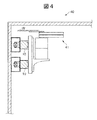
- the electric actuator 10 can be disposed upward in the substrate transfer chamber.
- the transfer module 40 serving as a substrate transfer chamber, two electric actuators 10 for moving a scalar type transfer arm 41 (substrate transfer device) are disposed above the transfer module 40.
- the wafer W can be transferred by jumping over other transfer arms and wafer buffers arranged in the lower part of the transfer module 40, so that efficient transfer of the wafer W can be realized.
- the transfer path of the wafer W is increased in the transfer module 40, it is not necessary to arrange a large number of transfer arms only in the lower part of the transfer module 40, so that the installation area (footprint) of the transfer module 40 increases. Can be prevented.
- the side portion 21ab of the lower electrode 21a and the side portion 21bb of the upper electrode 21b have a simple flat plate shape, but at least one of the side portion 21ab and the side portion 21bb may be bent.
- the slider 12 is provided with a protruding portion 12a protruding toward the outside of the main body 11 and having two bent portions, and the side portion 21ab of the lower electrode 21a and the side portion 21bb of the upper electrode 21b
- the side portion 21ab and the side portion 21bb may be configured to bend along the protruding portion 12a with the protruding portion 12a interposed therebetween.
- the bent path 50a extends from the opening 13 to the open ends of the pair of electrodes 21 between the side portion 21ab of the lower electrode 21a and the protruding portion 12a of the slider 12, and between the side portion 21bb and the protruding portion 12a of the upper electrode 21b. , 50b are formed. Since the particles P that have flowed out from the inside of the main body 11 through the gap 19 to the outside of the main body 11 pass through the bent paths 50a and 50b, the protruding portions 12a and the side portions 21ab and 21bb are bent at the bent paths 50a and 50b. Collide with.
- the particles P stay in the bending paths 50 a and 50 b, so that the particles P can be prevented from flowing out from the open ends of the pair of electrodes 21. Further, in this modification, since the particle P is retained in the bending paths 50a and 50b by a collision with a member, that is, by a mechanical method, the particle P is the main body even if the particle P does not have a negative or positive charge. 11 can be prevented from leaving.
- the opening 13 of the main body 11 is opened to the side, but the opening 13 may be opened upward as shown in FIG. 5B, for example.
- gravity acts on the particles P flowing out of the main body 11 from the inside of the main body 11 through the gap 19 so as to return to the inside of the main body 11.
- the particles P can be reliably prevented from leaving the main body 11.
- gravity is applied to the particles P to return them to the inside of the main body 11, so that the particles P can be returned to the inside of the main body 11 even if they do not have a negative or positive charge.
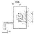
- an electric actuator when used in an environment of a predetermined pressure or higher, for example, in an atmospheric pressure environment, particles move by being caught in an air current.
- An exhaust device 62 for reducing the pressure inside is provided, and the pressure inside the main body 61 is set lower than the pressure outside the main body 61 to generate an air flow F flowing from the outside of the main body 61 to the inside. Prevents particles from flowing out from the inside.
- the corrosive gas may volatilize from the wafer when the wafer is transferred using an electric actuator in the substrate transfer chamber. is there. At this time, if the pressure inside the main body 61 is lower than the pressure outside the main body 61, the corrosive gas is sucked into the main body 61 and the rails, guides, and motors arranged inside the main body 61. May corrode.
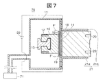
- the pressure inside the main body is set higher than the pressure outside the main body.
- FIG. 7 is a cross-sectional view schematically showing the configuration of the electric actuator according to the present embodiment.
- the electric actuator 70 includes a pressure control device 71 connected to the main body 11.
- the pressure control device 71 sends gas or the like into the main body 11 and maintains the pressure inside the main body 11 higher than the pressure outside the main body 11 (external pressure). Thereby, corrosive gas etc. are not attracted
- the gas sent from the pressure control device 71 to the inside of the main body 11 in the electric actuator 70 may be a corrosive gas, but for example, a dry gas made of an inert gas is preferable.
- the slider 12 is provided with a protruding portion 12a, and the side portion 21ab and the upper electrode 21b of the lower electrode 21a are provided.
- the side portions 21bb may be bent along the protruding portions 12a to form the bent paths 50a and 50b, and the opening 13 may be opened upward.
Landscapes
- Engineering & Computer Science (AREA)
- Mechanical Engineering (AREA)
- Robotics (AREA)
- Container, Conveyance, Adherence, Positioning, Of Wafer (AREA)
Abstract
Description
W ウエハ
10 電動アクチュエータ
11 本体
12 スライダ
12a 突出部
13 開口部
19 隙間
21 一対の電極
21a 下部電極
21b 上部電極
21ab,21bb 側部
22 直流電源
23 絶縁部材
41 搬送アーム
50a,50b 屈曲路
71 圧力制御装置
Claims (7)
- 細長状の筐体からなる本体と、該本体の長手方向に沿って往復自在に移動する基部と、該基部の移動路に対応して前記本体の側面に形成された開口部と、該開口部と覆うように設けられたシール部材とを備える電動アクチュエータにおいて、
前記開口部の両脇において当該開口部を挟むように前記本体から該本体の外側に向けて突出し、且つ前記本体の長手方向に沿って延設された一対の電極を備え、
前記一対の電極の一方には正の電位が生じ、前記一対の電極の他方には負の電位が生じることを特徴とする電動アクチュエータ。 - 前記本体の内部圧力が前記本体の外部圧力よりも高く維持されることを特徴とする請求項1記載の電動アクチュエータ。
- 前記基部は前記本体の外側に向けて突出する突出部を有し、
該突出部は少なくとも1つの屈曲箇所を有し、
前記一対の電極は前記基部の前記突出部を挟み、且つ前記挟まれた突出部に沿って屈曲することを特徴とする請求項1記載の電動アクチュエータ。 - 前記開口部は上方に向けて開口することを特徴とする請求項1記載の電動アクチュエータ。
- 前記基部には基板を搬送する基板搬送装置が取り付けられることを特徴とする請求項1の電動アクチュエータ。
- 前記一対の電極と前記本体との間には絶縁部材が介在し、前記一対の電極は前記本体から電気的に絶縁されることを特徴とする請求項1記載の電動アクチュエータ。
- 前記シール部材はシールバンドであることを特徴とする請求項1記載の電動アクチュエータ。
Priority Applications (2)
| Application Number | Priority Date | Filing Date | Title |
|---|---|---|---|
| US14/122,774 US9096395B2 (en) | 2011-06-24 | 2012-06-18 | Electric actuator |
| KR1020137032892A KR101680421B1 (ko) | 2011-06-24 | 2012-06-18 | 전동 액추에이터 |
Applications Claiming Priority (2)
| Application Number | Priority Date | Filing Date | Title |
|---|---|---|---|
| JP2011140460A JP5732329B2 (ja) | 2011-06-24 | 2011-06-24 | 電動アクチュエータ |
| JP2011-140460 | 2011-06-24 |
Publications (1)
| Publication Number | Publication Date |
|---|---|
| WO2012176913A1 true WO2012176913A1 (ja) | 2012-12-27 |
Family
ID=47422740
Family Applications (1)
| Application Number | Title | Priority Date | Filing Date |
|---|---|---|---|
| PCT/JP2012/066089 Ceased WO2012176913A1 (ja) | 2011-06-24 | 2012-06-18 | 電動アクチュエータ |
Country Status (5)
| Country | Link |
|---|---|
| US (1) | US9096395B2 (ja) |
| JP (1) | JP5732329B2 (ja) |
| KR (1) | KR101680421B1 (ja) |
| TW (1) | TWI525030B (ja) |
| WO (1) | WO2012176913A1 (ja) |
Families Citing this family (3)
| Publication number | Priority date | Publication date | Assignee | Title |
|---|---|---|---|---|
| DE102014118972A1 (de) * | 2014-12-18 | 2016-06-23 | Weber Maschinenbau Gmbh Breidenbach | Bewegungsvorrichtung mit Abdeckung |
| JP7032927B2 (ja) * | 2017-12-28 | 2022-03-09 | 日本電産サンキョー株式会社 | 産業用ロボット |
| KR102366179B1 (ko) | 2019-08-23 | 2022-02-22 | 세메스 주식회사 | 반송 장치 및 이를 가지는 기판 처리 장치 |
Citations (6)
| Publication number | Priority date | Publication date | Assignee | Title |
|---|---|---|---|---|
| JPH08290384A (ja) * | 1995-04-18 | 1996-11-05 | Nippon Seiko Kk | 低発塵直動アクチュエータ |
| JP2000197304A (ja) * | 1998-12-28 | 2000-07-14 | Iai:Kk | アクチュエ―タ |
| JP2002353086A (ja) * | 2001-05-30 | 2002-12-06 | Sony Corp | 半導体製造装置及び半導体製造方法 |
| JP2005321062A (ja) * | 2004-05-11 | 2005-11-17 | Nippon Thompson Co Ltd | 低発塵用スライド装置 |
| JP2008211018A (ja) * | 2007-02-27 | 2008-09-11 | Kyocera Corp | 試料ホルダとそれを用いた検査装置および試料処理方法 |
| JP2010225641A (ja) * | 2009-03-19 | 2010-10-07 | Tokyo Electron Ltd | 基板搬送装置及び基板搬送方法 |
Family Cites Families (9)
| Publication number | Priority date | Publication date | Assignee | Title |
|---|---|---|---|---|
| JPH0751756B2 (ja) * | 1985-11-09 | 1995-06-05 | 日電アネルバ株式会社 | 集塵装置付薄膜処理装置 |
| JPS6422042A (en) * | 1987-07-17 | 1989-01-25 | Kyushu Nippon Electric | Vacuum transfer chamber of semiconductor manufacturing equipment |
| JPH05283510A (ja) * | 1992-03-31 | 1993-10-29 | Nippon Seiko Kk | 位置決めテーブル装置 |
| JP3570077B2 (ja) * | 1996-05-08 | 2004-09-29 | 日本精工株式会社 | 無吸引クリーンアクチュエータ |
| JP2000230618A (ja) * | 1999-02-10 | 2000-08-22 | Thk Co Ltd | 防塵型案内装置 |
| US6832680B1 (en) * | 2001-09-03 | 2004-12-21 | Hirata Corporation | Work conveying system and traveling path sealing structure in the work conveying system |
| JP4155781B2 (ja) * | 2001-11-26 | 2008-09-24 | 日本トムソン株式会社 | スライド装置のシール構造 |
| US6935828B2 (en) * | 2002-07-17 | 2005-08-30 | Transfer Engineering And Manufacturing, Inc. | Wafer load lock and magnetically coupled linear delivery system |
| JP4753092B2 (ja) * | 2007-07-18 | 2011-08-17 | 株式会社安川電機 | 防塵機構を備えた基板搬送ロボット及びそれを備えた半導体製造装置 |
-
2011
- 2011-06-24 JP JP2011140460A patent/JP5732329B2/ja active Active
-
2012
- 2012-06-15 TW TW101121612A patent/TWI525030B/zh active
- 2012-06-18 KR KR1020137032892A patent/KR101680421B1/ko active Active
- 2012-06-18 WO PCT/JP2012/066089 patent/WO2012176913A1/ja not_active Ceased
- 2012-06-18 US US14/122,774 patent/US9096395B2/en active Active
Patent Citations (6)
| Publication number | Priority date | Publication date | Assignee | Title |
|---|---|---|---|---|
| JPH08290384A (ja) * | 1995-04-18 | 1996-11-05 | Nippon Seiko Kk | 低発塵直動アクチュエータ |
| JP2000197304A (ja) * | 1998-12-28 | 2000-07-14 | Iai:Kk | アクチュエ―タ |
| JP2002353086A (ja) * | 2001-05-30 | 2002-12-06 | Sony Corp | 半導体製造装置及び半導体製造方法 |
| JP2005321062A (ja) * | 2004-05-11 | 2005-11-17 | Nippon Thompson Co Ltd | 低発塵用スライド装置 |
| JP2008211018A (ja) * | 2007-02-27 | 2008-09-11 | Kyocera Corp | 試料ホルダとそれを用いた検査装置および試料処理方法 |
| JP2010225641A (ja) * | 2009-03-19 | 2010-10-07 | Tokyo Electron Ltd | 基板搬送装置及び基板搬送方法 |
Also Published As
| Publication number | Publication date |
|---|---|
| JP5732329B2 (ja) | 2015-06-10 |
| KR101680421B1 (ko) | 2016-11-28 |
| KR20140031309A (ko) | 2014-03-12 |
| US9096395B2 (en) | 2015-08-04 |
| JP2013008835A (ja) | 2013-01-10 |
| US20140110224A1 (en) | 2014-04-24 |
| TWI525030B (zh) | 2016-03-11 |
| TW201318944A (zh) | 2013-05-16 |
Similar Documents
| Publication | Publication Date | Title |
|---|---|---|
| JP5624529B2 (ja) | 手振れ補正装置及び撮像装置 | |
| CN101535010B (zh) | 用于机械手肘关节组件的方法和装置 | |
| JP5703627B2 (ja) | 静電誘導発電デバイス、静電誘導発電機器 | |
| JP5732329B2 (ja) | 電動アクチュエータ | |
| US8704621B2 (en) | Electromagnetic relay | |
| CN109643680B (zh) | 磁悬浮系统、用于磁悬浮系统的载体和操作磁悬浮系统的方法 | |
| US8624503B2 (en) | Collector-radiator structure for an electrohydrodynamic cooling system | |
| US9475094B2 (en) | Vibration generating apparatus | |
| CN104838463A (zh) | 具有稳定的可移动触头的电磁开关 | |
| US11187226B2 (en) | Actuating-type gas guiding device | |
| JP5523436B2 (ja) | 半導体清浄装置および半導体清浄方法 | |
| CN103459042A (zh) | 抗裂性多层发射极结构 | |
| CN111994584A (zh) | 物品输送体 | |
| JP4679813B2 (ja) | パーティクル付着防止装置及び方法、大気搬送装置、真空搬送装置、並びに半導体製造装置 | |
| JP2013212920A (ja) | 搬送アーム、搬送装置および搬送方法 | |
| JP6451527B2 (ja) | ミニエンバイロメント装置 | |
| US10428817B2 (en) | Cooling arrangement for cooling an apparatus | |
| JP6890696B2 (ja) | 磁気平衡式直線振動モーター | |
| CN120239159A (zh) | 末端执行器和基板传送装置 | |
| JP4882479B2 (ja) | 電源装置およびそれを備えた電気器具 | |
| JP2012002408A (ja) | ミニエンバイロメント装置 | |
| JP2019205989A (ja) | 電気集塵装置及び熱交換システム | |
| Gehlke et al. | The Role of Air Ionization in Reducing Surface Contamination by Particles in the Cleanroom | |
| JP4658872B2 (ja) | シールドカバー、微細駆動装置、ナノピンセット装置および試料観察装置 | |
| US8987950B2 (en) | Actuator and actuator cooling method |
Legal Events
| Date | Code | Title | Description |
|---|---|---|---|
| 121 | Ep: the epo has been informed by wipo that ep was designated in this application |
Ref document number: 12801987 Country of ref document: EP Kind code of ref document: A1 |
|
| WWE | Wipo information: entry into national phase |
Ref document number: 14122774 Country of ref document: US |
|
| ENP | Entry into the national phase |
Ref document number: 20137032892 Country of ref document: KR Kind code of ref document: A |
|
| NENP | Non-entry into the national phase |
Ref country code: DE |
|
| 122 | Ep: pct application non-entry in european phase |
Ref document number: 12801987 Country of ref document: EP Kind code of ref document: A1 |