WO2012176641A1 - スプリング式一方向クラッチ - Google Patents
スプリング式一方向クラッチ Download PDFInfo
- Publication number
- WO2012176641A1 WO2012176641A1 PCT/JP2012/064890 JP2012064890W WO2012176641A1 WO 2012176641 A1 WO2012176641 A1 WO 2012176641A1 JP 2012064890 W JP2012064890 W JP 2012064890W WO 2012176641 A1 WO2012176641 A1 WO 2012176641A1
- Authority
- WO
- WIPO (PCT)
- Prior art keywords
- coil spring
- diameter
- diameter coil
- spring
- clutch
- Prior art date
- Legal status (The legal status is an assumption and is not a legal conclusion. Google has not performed a legal analysis and makes no representation as to the accuracy of the status listed.)
- Ceased
Links
Images



Classifications
-
- F—MECHANICAL ENGINEERING; LIGHTING; HEATING; WEAPONS; BLASTING
- F16—ENGINEERING ELEMENTS AND UNITS; GENERAL MEASURES FOR PRODUCING AND MAINTAINING EFFECTIVE FUNCTIONING OF MACHINES OR INSTALLATIONS; THERMAL INSULATION IN GENERAL
- F16D—COUPLINGS FOR TRANSMITTING ROTATION; CLUTCHES; BRAKES
- F16D41/00—Freewheels or freewheel clutches
- F16D41/20—Freewheels or freewheel clutches with expandable or contractable clamping ring or band
- F16D41/206—Freewheels or freewheel clutches with expandable or contractable clamping ring or band having axially adjacent coils, e.g. helical wrap-springs
-
- E—FIXED CONSTRUCTIONS
- E05—LOCKS; KEYS; WINDOW OR DOOR FITTINGS; SAFES
- E05Y—INDEXING SCHEME ASSOCIATED WITH SUBCLASSES E05D AND E05F, RELATING TO CONSTRUCTION ELEMENTS, ELECTRIC CONTROL, POWER SUPPLY, POWER SIGNAL OR TRANSMISSION, USER INTERFACES, MOUNTING OR COUPLING, DETAILS, ACCESSORIES, AUXILIARY OPERATIONS NOT OTHERWISE PROVIDED FOR, APPLICATION THEREOF
- E05Y2201/00—Constructional elements; Accessories therefor
- E05Y2201/40—Motors; Magnets; Springs; Weights; Accessories therefor
- E05Y2201/47—Springs
- E05Y2201/49—Wrap springs
-
- E—FIXED CONSTRUCTIONS
- E05—LOCKS; KEYS; WINDOW OR DOOR FITTINGS; SAFES
- E05Y—INDEXING SCHEME ASSOCIATED WITH SUBCLASSES E05D AND E05F, RELATING TO CONSTRUCTION ELEMENTS, ELECTRIC CONTROL, POWER SUPPLY, POWER SIGNAL OR TRANSMISSION, USER INTERFACES, MOUNTING OR COUPLING, DETAILS, ACCESSORIES, AUXILIARY OPERATIONS NOT OTHERWISE PROVIDED FOR, APPLICATION THEREOF
- E05Y2800/00—Details, accessories and auxiliary operations not otherwise provided for
- E05Y2800/20—Combinations of elements
- E05Y2800/205—Combinations of elements forming a unit
-
- E—FIXED CONSTRUCTIONS
- E05—LOCKS; KEYS; WINDOW OR DOOR FITTINGS; SAFES
- E05Y—INDEXING SCHEME ASSOCIATED WITH SUBCLASSES E05D AND E05F, RELATING TO CONSTRUCTION ELEMENTS, ELECTRIC CONTROL, POWER SUPPLY, POWER SIGNAL OR TRANSMISSION, USER INTERFACES, MOUNTING OR COUPLING, DETAILS, ACCESSORIES, AUXILIARY OPERATIONS NOT OTHERWISE PROVIDED FOR, APPLICATION THEREOF
- E05Y2800/00—Details, accessories and auxiliary operations not otherwise provided for
- E05Y2800/20—Combinations of elements
- E05Y2800/22—Combinations of elements of not identical elements of the same category, e.g. combinations of not identical springs
Definitions
- This invention relates to a spring-type one-way clutch that transmits one-way rotation of a driving member to a driven member.
- a spring type that transmits and shuts off a one-way rotational torque by tightening and releasing a clutch spring has been conventionally known. It has been.
- the spring-type one-way clutch includes a single-spring type in which the clutch spring is single, and a double spring as described in Patent Document 1. There is a double spring type.
- the spring is installed in one direction of the drive shaft as an assembly over the shaft ends of the drive shaft (drive arbor) and the driven shaft (driven arbor) arranged on the same axis.
- the rotation of the clutch spring reduces the diameter of the clutch spring, and the clutch spring tightens the drive shaft and the driven shaft to transmit the rotation of the drive shaft in one direction to the driven shaft. Since it is necessary to use a clutch spring having a large number of windings, there is a problem that the axial direction length of the one-way clutch becomes long and the size is increased.
- the large-diameter coil spring portion of the double clutch spring is brought into elastic contact with the clutch surface formed on the inner periphery of the drive wheel, and the small-diameter coil spring portion is engaged.
- the assembly is elastically brought into contact with the clutch surface formed on the outer periphery of the driving wheel, and when the drive wheel rotates in one direction, the large-diameter coil spring portion is enlarged and the small-diameter coil spring portion is reduced in diameter.
- the diameter coil spring portion tightens the clutch surface of the driving wheel and the small diameter coil spring portion tightens the clutch surface of the driven wheel, thereby coupling the driving wheel and the driven wheel to generate a rotational torque in one direction of the driving wheel.
- the transmission torque capacity is large, and a compact one-way clutch with a length in the axial direction can be obtained. .
- the clutch spring is a large-diameter coil spring.
- Part and small-diameter coil spring part are connected through a continuous part composed of a U-shaped reversing part that bends 180 °, so that each time rotation is transmitted from the drive wheel to the driven wheel, A relatively large stress is repeatedly applied to the reversal part having a small radius of curvature, and the stress is accumulated in the above-mentioned connecting portion, and the connecting portion is easily damaged by fatigue, and the durability of the clutch spring is improved. There are some points that need to be improved.
- An object of the present invention is to improve the durability and assembly of the clutch spring in the axially compact double spring type one-way clutch.
- an outer member having an outer tube portion, and an inner tube portion provided on an inner surface of a flange portion facing inward from one end of the outer tube portion,
- An inner member that is inserted into the flange portion and arranged coaxially with the outer member; and a clutch spring that transmits and blocks rotational torque between the inner member and the outer member.
- a spring is provided with a continuous portion extending inwardly from the winding end of the large diameter coil spring portion in the same winding direction as the large diameter coil spring portion, and the large diameter coil spring is provided at the small diameter end of the continuous portion
- a small-diameter coil spring portion having a winding direction different from that of the coil portion is connected continuously, and the small-diameter coil spring portion is arranged in the large-diameter coil spring portion, and the large-diameter coil spring portion tightly connects the outer diameter surface of the inner cylinder portion.
- the small-diameter coil spring portion is incorporated so as to bind the cylindrical outer diameter surface of the inner member, and the opening at the other end of the outer member is closed by incorporating an annular lid, and the lid is closed outward.
- a structure in which the lid, the clutch spring, and the outer member are unitized by being connected to the member is adopted.
- one of the outer member and the inner member is the drive side, and the other is the driven side.
- the large-diameter coil spring portion is reduced in diameter and the outer-diameter surface of the inner cylinder portion is reduced.
- the large-diameter coil spring portion rotates together with the outer member, and the rotation is transmitted to the small-diameter coil spring portion via the connecting portion.
- the small-diameter coil spring portion since the winding direction of the large-diameter coil spring portion and the small-diameter coil spring portion is different, the small-diameter coil spring portion has a reduced diameter and strongly tightens the cylindrical outer diameter surface of the inner member. Is transmitted to the inner member via the clutch spring, and the inner member rotates in the same direction as the outer member.
- the small-diameter coil spring is applied when the binding force of the large-diameter coil spring portion is stronger than that of the small-diameter coil spring.
- the diameter of the portion increases, slip occurs at the contact portion between the small-diameter coil spring portion and the inner member, the rotation of the outer member is not transmitted to the inner member, and the outer member idles.
- a spiral groove portion that can accommodate a continuous portion of the clutch spring is provided at the distal end portion of the inner cylinder portion, and the cover body is fitted into the distal end portion of the inner cylinder portion.
- annular engagement groove is provided on one of the outer diameter surface of the support cylinder portion and the inner diameter surface of the tip end portion of the inner cylinder portion, and an engagement convex portion that is engaged with the engagement groove is formed on the other side.
- the inner diameter surface of the flange portion and the inner diameter surface of the lid body are radial bearing surfaces that relatively rotatably support the outer member and the inner member, so that the outer member and the inner member are accurately relative to each other. Can be rotated.
- the outer member when a hook piece is provided at the winding start end of the large-diameter coil spring portion of the clutch spring, and the hook piece is locked to the outer cylinder portion of the outer member, the outer member can be used as a drive side in use.
- the rotation of the side member can be reliably transmitted to the large-diameter coil spring portion.
- the small diameter coil spring portion and the cylindrical outer diameter surface contact portion of the inner member can be caused to slip, and the sliding portion can be specified. it can.
- the outer member is formed of a synthetic resin molded product and has a lower hardness than the inner member made of metal, the outer member having a lower hardness is prevented from being worn by contact with the clutch spring. Can do.
- the large-diameter coil spring portion has a small binding force to tighten the inner cylinder portion. If the coil spring part is made stronger than the binding force for tightening the inner member, the contact between the small diameter coil spring part and the inner member is the same as when the hook piece part is locked to the outer cylinder part when torque transmission is interrupted. Slip can be caused at the portion, and wear of the outer member can be suppressed.
- an engagement groove extending in the axial direction from the other end surface of the outer cylinder portion is formed on the inner diameter surface of the outer cylinder portion, and the hook piece portion is engaged with the engagement groove so that the outer cylinder portion Since the hook piece portion can be engaged with the engagement groove when the clutch spring for fitting the large-diameter coil spring portion to the radial surface is assembled, the assembly of the clutch spring can be facilitated.
- the inside of the outer cylinder can be completely sealed, and the grease sealed inside leaks to the outside. In addition, it is possible to effectively prevent foreign matters from entering from the outside to the inside.
- the small-diameter coil spring portion When the inner member is the drive side, when the inner member is rotated in the direction opposite to the winding direction of the small-diameter coil spring portion, the small-diameter coil spring portion is reduced in diameter so that the cylindrical outer diameter surface of the inner member is reduced.
- the small diameter coil spring portion is rotated together with the inner member.
- the rotation is transmitted to the large-diameter coil spring portion through the continuous portion, and the large-diameter coil spring portion is reduced in diameter to strongly tighten the outer diameter surface of the inner cylinder portion, and the rotation of the inner member is performed via the clutch spring.
- the outer member is transmitted to the outer member, and the outer member rotates in the same direction as the inner member.
- the large-diameter coil spring portion and the small-diameter coil spring portion disposed inside thereof and having a winding direction different from that of the large-diameter coil spring portion are separated from the winding end of the large-diameter coil spring portion.
- the opening at the other end of the outer member is closed by incorporating an annular lid, the lid is connected to the outer member, and the lid, the clutch spring, and the outer member are unitized, so that the clutch
- the small-diameter coil spring portion expands in diameter, Since the inner member can be incorporated into the small-diameter coil spring portion, the one-way clutch can be incorporated very easily.
- the opening at the other end of the outer member can be closed by incorporating the lid, the leakage of the grease sealed between the opposing portions of the outer member and the inner member is prevented, and from the outside It is possible to prevent foreign matter from entering the inside.
- the spring type one-way clutch includes a unit product A and a rotating shaft 41 as an inward member assembled in the unit product A.
- the unit product A includes a drive gear 1 as an outer member, a clutch spring 21 incorporated in the drive gear 1, and the clutch spring 21 connected to the drive gear 1. It consists of a lid body 31 to prevent it from being removed.
- the drive gear 1 has an outer cylinder portion 2, and a large number of teeth 3 are formed in the circumferential direction on the outer diameter surface of the outer cylinder portion 2.
- An inward flange portion 4 is formed at one end of the outer cylinder portion 2, and an inner diameter surface of the flange portion 4 is a radial bearing surface 5 that rotatably supports the rotating shaft 41.
- the flange portion 4 is formed with an inner cylinder portion 6 on the inner surface thereof, and the inner cylinder portion 6 and the outer cylinder portion 2 are arranged coaxially.
- a large-diameter recess 8 is formed in the other end opening of the outer tube portion 2.
- the aforementioned lid 31 is fitted into the large-diameter recess 8, and the annular space 7 formed between the outer diameter surface 6 a of the inner cylinder portion 6 and the inner diameter surface 2 a of the outer cylinder portion 2 is closed by the lid body 31.
- the lid body 31 has been.
- the lid body 31 has an annular shape, and a support cylinder portion 32 formed on the inner periphery thereof is fitted in the distal end portion of the inner cylinder portion 6 to support the distal end portion of the inner cylinder portion 6.
- the inner diameter surface of the support cylinder portion 32 is a radial bearing surface 33 that rotatably supports the rotary shaft 41.
- An engagement convex portion 34 having a semicircular cross section is formed on the outer diameter surface of the support cylinder portion 32.
- the engaging convex portion 34 engages with an annular engaging groove 9 having a semicircular cross section formed on the inner diameter surface of the distal end portion of the inner cylinder portion 6, and the lid body 31 is prevented from being pulled out by the engagement. Is connected to
- the engagement groove 9 may be formed in the support cylinder portion 32, and the engagement protrusion 34 may be provided in the inner cylinder portion 6.
- the drive gear 1 and the lid 31 are formed of a synthetic resin, but the material is not limited to the synthetic resin, and may be a metal.
- the clutch spring 21 includes a large-diameter coil spring portion 22, an inward spiral-shaped continuous portion 23 that is continuously provided at the winding end of the large-diameter coil spring portion 22, and
- the small-diameter coil spring portion 24 is arranged on the inside of the large-diameter coil spring portion 22 so as to be continuous with the small-diameter end of the continuous portion 23, and outwards at the winding start end of the large-diameter coil spring portion 22.
- a hook piece 25 is formed.
- the winding directions of the large-diameter coil spring portion 22 and the small-diameter coil spring portion 24 are different.
- the large-diameter coil spring portion 22 is clockwise and the small-diameter coil spring portion 24 is counterclockwise, and the winding direction of the spiral continuous portion 23 is the same as the winding direction of the large-diameter coil spring portion 22. ing.
- the clutch spring 21 is incorporated so that the connecting portion 23 is accommodated in the spiral groove portion 10 formed at the distal end portion of the inner cylinder portion 6.
- the clutch spring 21 has a large-diameter coil spring portion 22 that binds to the outer-diameter surface 6 a of the inner cylinder portion 6, and a small-diameter coil spring portion 24 that binds to the cylindrical outer-diameter surface 41 a of the rotating shaft 41.
- a hook piece portion 25 provided at the winding start end of the spring portion 22 is incorporated into an axial engagement groove 11 formed on the inner diameter surface of the outer cylinder portion 2 of the drive gear 1.
- the small-diameter coil spring portion 24 is reduced in diameter and tightens the outer diameter surface 41a of the rotating shaft 41. Therefore, the rotation of the drive gear 1 is transmitted to the rotation shaft 41 via the clutch spring 21, and the rotation shaft 41 rotates in the same direction as the drive gear 1.
- the connecting portion 23 of the clutch spring 21 When transmitting the rotational torque from the drive gear 1 to the rotating shaft 41, the connecting portion 23 of the clutch spring 21 is loaded with a stress having a magnitude corresponding to the transmitted torque.
- the connecting portion 23 is assumed to be the same as the winding direction of the large-diameter coil spring portion 22 that rotates together with the drive gear 1 and extends inwardly from the winding end of the large-diameter coil spring portion 22. There is no case where stress is locally applied to the installation portion 23. Further, since the stress applied to the continuous portion 23 is received by the inner surface of the spiral groove portion 10, the continuous portion 23 is not damaged by fatigue.
- the clutch spring 21 slips at the contact portion with the rotating shaft 41 having a high hardness, so that the inner cylinder portion 6 of the driving gear 1 having a low hardness is worn. There is no.
- an annular lid 31 is incorporated in the large-diameter recess 8 formed in the other end opening of the drive gear 1, and the lid 31 is assembled.
- the lid 31 is connected to the drive gear 1 by the engagement of the engagement convex portion 34 on the outer diameter surface of the formed support cylinder portion 32 and the engagement groove 9 of the inner cylinder portion 6, so that the drive gear 1 and the clutch spring 21 are connected. Since the cover 31 is unitized, the end of the rotary shaft 41 is inserted into the small-diameter coil spring portion 24 of the clutch spring 21, and the winding direction of the small-diameter coil spring portion 24 is pushed in the axial direction. The small-diameter coil spring portion 24 is expanded by contact with the rotary shaft 41, and the rotary shaft 41 can be incorporated into the small-diameter coil spring portion 24. For this reason, the one-way clutch can be incorporated very easily.
Landscapes
- Engineering & Computer Science (AREA)
- General Engineering & Computer Science (AREA)
- Mechanical Engineering (AREA)
- Mechanical Operated Clutches (AREA)
Abstract
駆動ギヤ(1)の内向きフランジ部(4)に内筒部(6)を設け、駆動ギヤ(1)の内側に組み込まれるクラッチスプリング(21)に大径コイルスプリング部(22)と、その巻き終わり端に連設部(23)と、連設部(23)の小径端に巻き方向が大径コイルスプリング部(22)の巻き方向と相違する小径コイルスプリング部(24)とを設け、クラッチスプリング(21)を大径コイルスプリング部(22)が内筒部(6)の外径面を緊縛し、小径コイルスプリング部(24)が回転軸(41)の外径面を緊縛する組込みとし、駆動ギヤ(1)が大径コイルスプリング部(22)の巻き方向と反対の方向に回転した際に、大径コイルスプリング部(22)及び小径コイルスプリング部(24)を縮径させて、駆動ギヤ(1)の回転を回転軸(41)に伝達する。クラッチスプリング(21)の連設部(23)を巻き方向が大径コイルスプリング部(22)の巻き方向と同じとなる内向き渦巻き状として、駆動ギヤ(1)から回転軸(41)への回転トルクの伝達時に、連設部(23)に大きな応力が負荷されることのないようにしてクラッチスプリングの耐久性の向上を図る。駆動ギヤ(1)の他端の開口を環状の蓋体(31)の組込みにより閉塞し、蓋体(31)を駆動ギヤ(1)に連結して、蓋体(31)、クラッチスプリング(21)及び駆動ギヤ(1)をユニット化して、組立性の向上を図る。
Description
この発明は、駆動部材の一方向の回転を従動部材に伝達するスプリング式一方向クラッチに関する。
プリンタや複写機、ファクシミリなどの紙送り機構等に組込まれる一方向クラッチとして、クラッチスプリングの締め付けおよび解除によって一方向の回転トルクの伝達と遮断とを行うようにしたスプリング式のものが従来から知られている。
スプリング式一方向クラッチには、非特許文献1に記載されているように、クラッチスプリングが一重とされた一重スプリング式のものと、特許文献1に記載されているように、クラッチスプリングが二重とされた二重スプリング式とが存在する。
ここで、一重スプリング式の一方向クラッチにおいては、スプリングを同一軸上に配置された駆動軸(駆動アーバ)と従動軸(従動アーバ)の軸端部に跨る組付けとして、駆動軸の一方向の回転によりクラッチスプリングを縮径させ、そのクラッチスプリングが駆動軸と従動軸を締付ける作用により、駆動軸の一方向の回転を従動軸に伝えるようにしているが、伝達トルク容量が小さく、大きなトルクを伝達する場合には、巻き数の多いクラッチスプリングを用いる必要があるため、一方向クラッチの軸方向長さが長くなり、大型化するという問題がある。
一方、二重スプリング式一方向クラッチにおいては、2重とされたクラッチスプリングの大径コイルスプリング部を駆動輪の内周に形成されたクラッチ面に弾性接触させ、かつ、小径コイルスプリング部を従動輪の外周に形成されたクラッチ面に弾性接触させる組付けとし、駆動輪の一方向への回転時に、大径コイルスプリング部を拡径させ、かつ、小径コイルスプリング部を縮径させ、上記大径コイルスプリング部が駆動輪のクラッチ面を締付ける作用と、小径コイルスプリング部が従動輪のクラッチ面を締付ける作用により、駆動輪と従動輪を結合して駆動輪の一方向の回転トルクを従動輪に伝達するようにしているため、伝達トルク容量が大きく、軸方向長さのコンパクトな一方向クラッチを得ることができるという特徴を有している。
「機械要素活用マニュアル・ばね」、編者;ニッパツ・日本発条株式会社、発行;1995年2月15日、P.136
ところで、特許文献1に記載された二重スプリング式一方向クラッチにおいては、上記のように、軸方向長さのコンパクト化を図ることができるという特徴を有するものの、クラッチスプリングは、大径コイルスプリング部と小径コイルスプリング部とを180°折れ曲がるU字形の反転部からなる連設部を介して連設した構成であるため、駆動輪から従動輪に回転が伝達される度に、連設部の曲率半径の小さな反転部位に比較的大きな応力が繰り返し負荷されることになり、上記連設部にストレスが蓄積されて、その連設部が疲労によって破損し易く、クラッチスプリングの耐久性の向上を図る上において改善すべき点が残されている。
また、大径コイルスプリング部を縮径してクラッチスプリングを駆動輪内に組込み、そのクラッチスプリングの小径コイルスプリング部を拡径してその内側に従動輪を組付ける必要があるため、組立てに手間がかかり、その組立性を向上させる上においても改善すべき点が残されていた。
この発明の課題は、軸方向にコンパクトな二重スプリング式一方向クラッチにおいて、クラッチスプリングの耐久性の向上と組立性の向上を図ることである。
上記の課題を解決するため、この発明においては、外筒部を有し、その外筒部の一端から内方向に向くフランジ部の内側面に内筒部が設けられた外方部材と、前記フランジ部内に挿通されて外方部材と同軸上に配置された内方部材と、その内方部材と外方部材の相互間で回転トルクの伝達と遮断とを行うクラッチスプリングを有し、前記クラッチスプリングが、大径コイルスプリング部の巻き終わり端からその大径コイルスプリング部と巻き方向を同じとして内向き渦巻き状に延びる連設部を設け、その連設部の小径端に前記大径コイルスプリング部と巻方向が異なる小径コイルスプリング部を連設し、その小径コイルスプリング部を大径コイルスプリング部内に配置した構成とされて、大径コイルスプリング部が前記内筒部の外径面を緊縛し、小径コイルスプリング部が前記内方部材の円筒形外径面を緊縛する組込みとされ、前記外方部材の他端の開口を環状の蓋体の組込みにより閉塞し、その蓋体を外方部材に連結して、蓋体、クラッチスプリングおよび外方部材をユニット化した構成を採用したのである。
上記の構成からなるスプリング式一方向クラッチにおいては、外方部材と内方部材の一方を駆動側とし、他方を従動側とする。いま、外方部材を駆動側とし、その外方部材を大径コイルスプリング部の巻き方向と反対の方向に回転させると、大径コイルスプリング部が縮径して内筒部の外径面を強く締付け、大径コイルスプリング部が外方部材と共に回転し、その回転は連設部を介して小径コイルスプリング部に伝達される。
このとき、大径コイルスプリング部と小径コイルスプリング部とは巻き方向が相違するため、小径コイルスプリング部が縮径して内方部材の円筒状外径面を強く締付けることになり、外方部材の回転はクラッチスプリングを介して内方部材に伝達され、内方部材が外方部材と同方向に回転する。
一方、上記とは逆に、外方部材を大径コイルスプリング部の巻き方向に回転させると、大径コイルスプリング部の緊縛力が小径コイルスプリングの緊縛力より強い場合においては、その小径コイルスプリング部が拡径し、小径コイルスプリング部と内方部材の接触部で滑りが生じて、外方部材の回転が内方部材に伝達されず、外方部材が空転する。
ここで、外方部材から内方部材への回転トルクの伝達時、クラッチスプリングの連設部には伝達トルクに応じた大きさの応力が負荷されることになる。このとき、連設部は、外方部材と共に回転する大径コイルスプリング部の巻き方向と同じとして、その大径コイルスプリング部の巻き終わり端から内向き渦巻き状に延びるため、上記連設部に局部的に応力が負荷されるというようなことがない。このため、連設部が疲労によって破損するというようなことはない。
この発明に係るスプリング式一方向クラッチにおいて、内筒部の先端部にクラッチスプリングの連設部を収容可能とする渦巻き溝部を設け、蓋体には内筒部の先端部内に嵌合される支持筒部を設けることにより、その支持筒部によって内筒部の自由端である先端部を支持することができるため、内筒部の曲げ剛性を高め、内筒部の変形や破損を防止し、大径コイルスプリング部の縮径によって内筒部を確実に緊縛することができる。その結果、内筒部と大径コイルスプリング部の接触での滑りを防止し、その相互間において確実にトルク伝達することができる。
また、支持筒部の外径面と内筒部の先端部内径面の一方に環状の係合溝を設け、他方にその係合溝に係合される係合凸部を形成して、蓋体と外方部材とを連結することにより、内筒部の先端部内に支持筒部の先端部を嵌合して蓋体を内筒部に向けて押し込むことで係合溝に係合凸部が係合し、外方部材に対して蓋体を簡単に連結することができる。
さらに、フランジ部の内径面および蓋体の内径面を、外方部材と内方部材を相対的に回転自在に支持するラジアル軸受面とすることにより、外方部材と内方部材を精度よく相対回転させることができる。
また、クラッチスプリングにおける大径コイルスプリング部の巻き始め端にフック片部を設け、そのフック片部を外方部材の外筒部に係止すると、外方部材を駆動側とする使用において、外方部材の回転を大径コイルスプリング部に確実に伝達することができる。また、外方部材から内方部材への回転伝達の遮断時に、小径コイルスプリング部と内方部材の円筒状外径面の接触部で滑りを生じさせることができ、滑り部位を特定することができる。
このため、外方部材が合成樹脂の成形品で形成されて金属からなる内方部材より硬度が低い場合に、その硬度の低い外方部材がクラッチスプリングとの接触で摩耗するのを防止することができる。
上記のように、外方部材および蓋体のそれぞれが合成樹脂の成形品とされて金属からなる内方部材の硬度より低い場合において、大径コイルスプリング部が内筒部を締め付ける緊縛力を小径コイルスプリング部が内方部材を締め付ける緊縛力より強くしておくと、トルク伝達の遮断時、フック片部を外筒部に係止する場合と同様に、小径コイルスプリング部と内方部材の接触部で滑りを生じさせることができ、外方部材の摩耗を抑制することができる。
ここで、外筒部の内径面に、その外筒部の他端面から軸方向に延びる係合溝を形成し、その係合溝にフック片部を係合させることにより、内筒部の外径面に大径コイルスプリング部を嵌合するクラッチスプリングの組付け時にフック片部を係合溝に係合させることができるため、クラッチスプリングの組付けの容易化を図ることができる。
また、外筒部の他端開口部に蓋体が嵌合される大径凹部を設けておくと、外筒部内を完全に密閉することができ、内部に封入されたグリースの外部への漏洩および外部から内部への異物の侵入を効果的に防止することができる。
なお、内方部材を駆動側とした場合、その内方部材を小径コイルスプリング部の巻き方向の反対方向に回転すると、小径コイルスプリング部が縮径して内方部材の円筒状外径面を締め付け、小径コイルスプリング部が内方部材と共に回転する。その回転は連設部を介して大径コイルスプリング部に伝達され、大径コイルスプリング部が縮径して内筒部の外径面を強く締め付け、内方部材の回転はクラッチスプリングを介して外方部材に伝達され、外方部材が内方部材と同方向に回転する。
この場合においても、クラッチスプリングの連設部に局部的に応力が負荷されるというようなことがなく、連設部が疲労によって破損するというようなことはない。
この発明においては、上記のように、大径コイルスプリング部と、その内側に配置されて大径コイルスプリング部と巻き方向が異なる小径コイルスプリング部とを、大径コイルスプリング部の巻き終わり端から内向き渦巻き状に延びる連設部によって連設したことにより、外方部材と内方部材の相互間における回転トルクの伝達時に、連設部に局部的に応力が負荷されるのを防止することができる。このため、連設部が疲労によって破損するということが極めて少なくなり、クラッチスプリングの耐久性の向上を図ることができる。
また、外方部材の他端の開口を環状の蓋体の組込みにより閉塞し、その蓋体を外方部材に連結して、蓋体、クラッチスプリングおよび外方部材をユニット化したことにより、クラッチスプリングの小径コイルスプリング部内に内方部材の端部を挿入し、その内方部材を軸方向に押し込みつつ小径コイルスプリング部の巻き方向に回転させることにより、小径コイルスプリング部が拡径して、その小径コイルスプリング部内に内方部材を組み込むことができるため、一方向クラッチを極めて簡単に組込むことができる。
さらに、蓋体の組込みによって外方部材の他端の開口を閉塞することができるため、外方部材と内方部材の対向部間に封入されたグリースの外部への漏洩を防止し、外部から内部への異物の侵入を防止することができる。
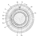
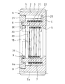
以下、この発明の実施の形態を図面に基づいて説明する。図1および図2に示すように、スプリング式一方向クラッチは、ユニット品Aと、そのユニット品A内に組付けられる内方部材としての回転軸41とからなる。
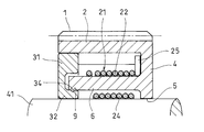
図3に示すように、ユニット品Aは、外方部材としての駆動ギヤ1と、その駆動ギヤ1の内部に組み込まれたクラッチスプリング21と、上記駆動ギヤ1に連結されてそのクラッチスプリング21を抜止めする蓋体31とからなる。
図3および図4に示すように、駆動ギヤ1は、外筒部2を有し、その外筒部2の外径面に多数の歯3が周方向に形成されている。外筒部2の一端には、内向きのフランジ部4が形成され、そのフランジ部4の内径面は回転軸41を回転自在に支持するラジアル軸受面5とされている。また、フランジ部4には、その内側面に内筒部6が形成され、その内筒部6と外筒部2とは同軸上の配置とされている。
図3に示すように、外筒部2の他端開口部には大径凹部8が形成されている。大径凹部8内には前述の蓋体31が嵌合され、その蓋体31によって内筒部6の外径面6aと外筒部2の内径面2a間に形成された環状空間7が閉塞されている。
蓋体31は環状をなし、その内周部に形成された支持筒部32は内筒部6の先端部内に嵌合されて、その内筒部6の先端部を支持している。また、支持筒部32の内径面は回転軸41を回転自在に支持するラジアル軸受面33とされている。
支持筒部32の外径面には断面半円形の係合凸部34が形成されている。係合凸部34は内筒部6の先端部内径面に形成された断面半円形の環状の係合溝9と係合し、その係合により蓋体31が抜止めされて、駆動ギヤ1に対する連結とされている。
なお、図7に示すように、支持筒部32に係合溝9を形成し、内筒部6に係合凸部34を設けるようにしてもよい。
ここで、実施の形態では、駆動ギヤ1および蓋体31は合成樹脂の成形品とされているが、素材は合成樹脂に限定されるものではなく、金属であってもよい。
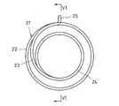
図5および図6に示すように、クラッチスプリング21は、大径コイルスプリング部22と、その大径コイルスプリング部22の巻き終わり端に連設された内向き渦巻き状の連設部23と、その連設部23の小径端に連設されて大径コイルスプリング部22の内側に配置された小径コイルスプリング部24とからなり、上記大径コイルスプリング部22の巻き始め端には外向きにフック片部25が形成されている。
ここで、大径コイルスプリング部22と小径コイルスプリング部24の巻き方向は相違している。実施の形態では、大径コイルスプリング部22を右巻きとし、小径コイルスプリング部24を左巻きとしており、渦巻き状連設部23の巻き方向は大径コイルスプリング部22の巻き方向と同じ方向とされている。
上記クラッチスプリング21は、図1乃至図3に示すように、連設部23が内筒部6の先端部に形成された渦巻き溝部10に収容される組込みとされている。また、クラッチスプリング21は、大径コイルスプリング部22が内筒部6の外径面6aを緊縛し、小径コイルスプリング部24が回転軸41の円筒状外径面41aを緊縛し、大径コイルスプリング部22の巻き始め端に設けられたフック片部25が駆動ギヤ1の外筒部2の内径面に形成された軸方向の係合溝11に係合する組込みとされている。
上記の構成から成るスプリング式一方向クラッチにおいて、駆動ギヤ1を図2の矢印で示すように、大径コイルスプリング部22の巻き方向と反対の方向に回転させると、大径コイルスプリング部22が縮径して内筒部6の外径面6aをさらに強く締め付け、大径コイルスプリング部22が駆動ギヤ1と共に回転する。その回転は連設部23を介して小径コイルスプリング部24に伝達される。
このとき、大径コイルスプリング部22と小径コイルスプリング部24とは巻き方向が相違するため、小径コイルスプリング部24が縮径して回転軸41の外径面41aを締付ける。このため、駆動ギヤ1の回転はクラッチスプリング21を介して回転軸41に伝達され、回転軸41が駆動ギヤ1と同方向に回転する。
駆動ギヤ1から回転軸41への回転トルクの伝達時、クラッチスプリング21の連設部23には伝達トルクに応じた大きさの応力が負荷されることになる。このとき、連設部23は、駆動ギヤ1と共に回転する大径コイルスプリング部22の巻き方向と同じとして、その大径コイルスプリング部22の巻き終わり端から内向き渦巻き状に延びるため、上記連設部23に局部的に応力が負荷されるというようなことがない。また、その連設部23に負荷される応力は渦巻き溝部10の内面で受けられるため、連設部23が疲労によって破損するというようなことはない。
一方、駆動ギヤ1を上記と逆に、図2の矢印で示す方向と反対の方向(大径コイルスプリング部22の巻き方向と同方向)に回転させると、その回転はフック片部25から大径コイルスプリング部22に伝達されると共に、その大径コイルスプリング部22の回転は連設部23を介して小径コイルスプリング部24に伝達されて、その小径コイルスプリング部24が拡径する。その拡径により、小径コイルスプリング部24と回転軸41の外径面41aとの接触部で滑りが生じ、駆動ギヤ1の回転は回転軸41に伝達されず、駆動ギヤ1が空転する。
回転伝達の遮断時は、上記のように、クラッチスプリング21は硬度の高い回転軸41との接触部で滑りが生じるため、硬度の低い駆動ギヤ1の内筒部6が摩耗すると言うようなことがない。
実施の形態で示すスプリング式一方向クラッチのように、駆動ギヤ1および蓋体31のそれぞれが合成樹脂の成形品とされて金属からなる回転軸41の硬度より低い場合において、大径コイルスプリング部22が内筒部6を締め付ける緊縛力を小径コイルスプリング部24が回転軸41を締め付ける緊縛力より強くしておくと、トルク伝達の遮断時、小径コイルスプリング部24と回転軸41の接触部で滑りを生じさせることができ、内筒部6の摩耗を防止することができる。
実施の形態におけるスプリング式一方向クラッチにおいては、図3に示すように、駆動ギヤ1の他端開口部に形成された大径凹部8内に環状の蓋体31を組込み、その蓋体31に形成された支持筒部32の外径面の係合凸部34と内筒部6の係合溝9の係合により蓋体31を駆動ギヤ1に連結して、駆動ギヤ1、クラッチスプリング21および蓋体31をユニット化したことにより、クラッチスプリング21の小径コイルスプリング部24内に回転軸41の端部を挿入し、その回転軸41を軸方向に押し込みつつ小径コイルスプリング部24の巻き方向に回転させることにより、回転軸41との接触により小径コイルスプリング部24が拡径して、その小径コイルスプリング部24内に回転軸41を組み込むことができる。このため、一方向クラッチを極めて簡単に組込むことができる。
また、蓋体31の組込みによって駆動ギヤ1の他端の開口が閉塞されるため、駆動ギヤ1の内部に封入されたグリースの外部への漏洩を防止し、かつ、外部から内部への異物の侵入を防止することができる。
A ユニット品
1 駆動ギヤ (外方部材)
2 外筒部
4 フランジ部
5 ラジアル軸受面
6 内筒部
6a 外径面
8 大径凹部
9 係合溝
10 渦巻き溝部
11 係合溝
21 クラッチスプリング
22 大径コイルスプリング部
23 連設部
24 小径コイルスプリング部
25 フック片部
31 蓋体
32 支持筒部
33 ラジアル軸受面
34 係合凸部
41 回転軸(内方部材)
41a 外径面
1 駆動ギヤ (外方部材)
2 外筒部
4 フランジ部
5 ラジアル軸受面
6 内筒部
6a 外径面
8 大径凹部
9 係合溝
10 渦巻き溝部
11 係合溝
21 クラッチスプリング
22 大径コイルスプリング部
23 連設部
24 小径コイルスプリング部
25 フック片部
31 蓋体
32 支持筒部
33 ラジアル軸受面
34 係合凸部
41 回転軸(内方部材)
41a 外径面
Claims (8)
- 外筒部を有し、その外筒部の一端から内方向に向くフランジ部の内側面に内筒部が設けられた外方部材と、前記フランジ部内に挿通されて外方部材と同軸上に配置された内方部材と、その内方部材と外方部材の相互間で回転トルクの伝達と遮断とを行うクラッチスプリングを有し、前記クラッチスプリングが、大径コイルスプリング部の巻き終わり端からその大径コイルスプリング部と巻き方向を同じとして内向き渦巻き状に延びる連設部を設け、その連設部の小径端に前記大径コイルスプリング部と巻方向が異なる小径コイルスプリング部を連設し、その小径コイルスプリング部を大径コイルスプリング部内に配置した構成とされて、大径コイルスプリング部が前記内筒部の外径面を緊縛し、小径コイルスプリング部が前記内方部材の円筒形外径面を緊縛する組込みとされ、前記外方部材の他端の開口を環状の蓋体の組込みにより閉塞し、その蓋体を外方部材に連結して、蓋体、クラッチスプリングおよび外方部材をユニット化したスプリング式一方向クラッチ。
- 前記内筒部の先端部に前記クラッチスプリングの連設部を収容可能とする渦巻き溝部を設け、前記蓋体には前記内筒部の先端部内に嵌合されて、その内筒部の先端部を支持する支持筒部を設けた請求項1に記載のスプリング式一方向クラッチ。
- 前記支持筒部の外径面と内筒部の先端部内径面の一方に環状の係合溝を設け、他方にその係合溝に係合される係合凸部を形成して、蓋体と外方部材とを連結した請求項2に記載のスプリング式一方向クラッチ。
- 前記フランジ部の内径面および蓋体の内径面が、外方部材と内方部材を相対的に回転自在に支持するラジアル軸受面とされた請求項1乃至3のいずれかの項に記載のスプリング式一方向クラッチ。
- 前記クラッチスプリングの大径コイルスプリング部が、巻き始め端にフック片部を有し、そのフック片部が前記外方部材の外筒部に係止された請求項1乃至4のいずれかの項に記載のスプリング式一方向クラッチ。
- 前記外筒部の内径面に、その外筒部の他端面から軸方向に延びる係合溝を形成し、その係合溝に前記フック片部を係合した請求項5に記載のスプリング式一方向クラッチ。
- 前記外方部材と蓋体のそれぞれを合成樹脂の成形品とし、前記大径コイルスプリング部が内筒部を締め付ける緊縛力を小径コイルスプリング部が内方部材を締め付ける緊縛力より強くした請求項1乃至5のいずれかの項に記載のスプリング式一方向クラッチ。
- 前記外筒部の他端開口部に大径凹部を設け、その大径凹部に前記蓋体を嵌合した請求項1乃至7のいずれかの項に記載のスプリング式一方向クラッチ。
Applications Claiming Priority (2)
| Application Number | Priority Date | Filing Date | Title |
|---|---|---|---|
| JP2011139271A JP2013007412A (ja) | 2011-06-23 | 2011-06-23 | スプリング式一方向クラッチ |
| JP2011-139271 | 2011-06-23 |
Publications (1)
| Publication Number | Publication Date |
|---|---|
| WO2012176641A1 true WO2012176641A1 (ja) | 2012-12-27 |
Family
ID=47422481
Family Applications (1)
| Application Number | Title | Priority Date | Filing Date |
|---|---|---|---|
| PCT/JP2012/064890 Ceased WO2012176641A1 (ja) | 2011-06-23 | 2012-06-11 | スプリング式一方向クラッチ |
Country Status (2)
| Country | Link |
|---|---|
| JP (1) | JP2013007412A (ja) |
| WO (1) | WO2012176641A1 (ja) |
Cited By (5)
| Publication number | Priority date | Publication date | Assignee | Title |
|---|---|---|---|---|
| CN105697573A (zh) * | 2014-12-15 | 2016-06-22 | 舍弗勒技术股份两合公司 | 具有摩擦装置的组件 |
| WO2018086653A1 (de) * | 2016-11-08 | 2018-05-17 | Schaeffler Technologies AG & Co. KG | Doppelschlingfeder, rotationseinrichtung und zu aktuierendes system |
| CN110834677A (zh) * | 2018-08-16 | 2020-02-25 | 保时捷股份公司 | 用于机动车辆功能件的驱动组件 |
| DE102015217164B4 (de) | 2014-09-11 | 2022-03-24 | Schaeffler Technologies AG & Co. KG | Baugruppe mit einer Reibeinrichtung |
| US20230193961A1 (en) * | 2020-06-22 | 2023-06-22 | Origin Company, Limited | Bidirectional torque limiter |
Families Citing this family (1)
| Publication number | Priority date | Publication date | Assignee | Title |
|---|---|---|---|---|
| DE102017114444A1 (de) * | 2017-06-29 | 2019-01-03 | Schaeffler Technologies AG & Co. KG | Tilgereinrichtung |
Citations (5)
| Publication number | Priority date | Publication date | Assignee | Title |
|---|---|---|---|---|
| JPS50344U (ja) * | 1973-04-30 | 1975-01-06 | ||
| US4763764A (en) * | 1987-06-12 | 1988-08-16 | General Motors Corporation | Wrapped spring, overrunning clutch assembly |
| US5909791A (en) * | 1996-02-02 | 1999-06-08 | Distefano; Carmelo Joseph Licciardi | Spring clutch |
| WO2004016964A1 (fr) * | 2002-07-17 | 2004-02-26 | Aktiebolaget Skf | Dispositif de palier a roue libre et poulie a roue libre |
| JP2008101740A (ja) * | 2006-10-20 | 2008-05-01 | Ntn Corp | スプリングクラッチ |
-
2011
- 2011-06-23 JP JP2011139271A patent/JP2013007412A/ja not_active Withdrawn
-
2012
- 2012-06-11 WO PCT/JP2012/064890 patent/WO2012176641A1/ja not_active Ceased
Patent Citations (5)
| Publication number | Priority date | Publication date | Assignee | Title |
|---|---|---|---|---|
| JPS50344U (ja) * | 1973-04-30 | 1975-01-06 | ||
| US4763764A (en) * | 1987-06-12 | 1988-08-16 | General Motors Corporation | Wrapped spring, overrunning clutch assembly |
| US5909791A (en) * | 1996-02-02 | 1999-06-08 | Distefano; Carmelo Joseph Licciardi | Spring clutch |
| WO2004016964A1 (fr) * | 2002-07-17 | 2004-02-26 | Aktiebolaget Skf | Dispositif de palier a roue libre et poulie a roue libre |
| JP2008101740A (ja) * | 2006-10-20 | 2008-05-01 | Ntn Corp | スプリングクラッチ |
Cited By (8)
| Publication number | Priority date | Publication date | Assignee | Title |
|---|---|---|---|---|
| DE102015217164B4 (de) | 2014-09-11 | 2022-03-24 | Schaeffler Technologies AG & Co. KG | Baugruppe mit einer Reibeinrichtung |
| CN105697573A (zh) * | 2014-12-15 | 2016-06-22 | 舍弗勒技术股份两合公司 | 具有摩擦装置的组件 |
| CN105697573B (zh) * | 2014-12-15 | 2022-03-29 | 舍弗勒技术股份两合公司 | 具有摩擦装置的组件 |
| WO2018086653A1 (de) * | 2016-11-08 | 2018-05-17 | Schaeffler Technologies AG & Co. KG | Doppelschlingfeder, rotationseinrichtung und zu aktuierendes system |
| CN110834677A (zh) * | 2018-08-16 | 2020-02-25 | 保时捷股份公司 | 用于机动车辆功能件的驱动组件 |
| CN110834677B (zh) * | 2018-08-16 | 2022-01-14 | 保时捷股份公司 | 用于机动车辆功能件的驱动组件 |
| US20230193961A1 (en) * | 2020-06-22 | 2023-06-22 | Origin Company, Limited | Bidirectional torque limiter |
| US11815147B2 (en) * | 2020-06-22 | 2023-11-14 | Origin Company, Limited | Bidirectional torque limiter |
Also Published As
| Publication number | Publication date |
|---|---|
| JP2013007412A (ja) | 2013-01-10 |
Similar Documents
| Publication | Publication Date | Title |
|---|---|---|
| JP5658053B2 (ja) | スプリング式一方向クラッチ | |
| JP2013007412A (ja) | スプリング式一方向クラッチ | |
| AU2014251241B2 (en) | Isolator decoupler | |
| WO2011001608A1 (ja) | 一方向クラッチ | |
| EP0368526B1 (en) | Clutch | |
| JP5799552B2 (ja) | プーリユニット | |
| WO2012077669A1 (ja) | 逆入力遮断クラッチ | |
| JP2008101740A (ja) | スプリングクラッチ | |
| JP2021067286A (ja) | 逆入力防止クラッチ | |
| JP5242510B2 (ja) | 逆入力遮断機構 | |
| WO2025115666A1 (ja) | トルクリミッタ | |
| CN104514820A (zh) | 单向机械离合器系统及包括这种系统的交流发电机 | |
| JP5030846B2 (ja) | 捩り振動低減装置 | |
| JP2012122542A (ja) | スプリング式一方向クラッチ | |
| JP6002709B2 (ja) | 内燃機関の変速機 | |
| JP4943927B2 (ja) | 釣用リール装置 | |
| JP5045644B2 (ja) | 一方向クラッチ及び一方向クラッチ内蔵型プーリ装置 | |
| JP7735032B2 (ja) | ラチェット型ワンウェイクラッチ | |
| JP2006077939A (ja) | 動力伝達装置 | |
| JP6388695B1 (ja) | コイルばねを備えたスプリングクラッチの構造 | |
| JP2011190858A (ja) | スプリング式一方向クラッチ | |
| WO2014136828A1 (ja) | 一方向クラッチ | |
| JP2006071059A (ja) | フレキシブルカップリング | |
| US9062719B2 (en) | Electrically actuated rotating band torque transmitting mechanism for hybrid and other transmissions | |
| JP2009210025A (ja) | 逆入力防止クラッチ |
Legal Events
| Date | Code | Title | Description |
|---|---|---|---|
| 121 | Ep: the epo has been informed by wipo that ep was designated in this application |
Ref document number: 12801999 Country of ref document: EP Kind code of ref document: A1 |
|
| NENP | Non-entry into the national phase |
Ref country code: DE |
|
| 122 | Ep: pct application non-entry in european phase |
Ref document number: 12801999 Country of ref document: EP Kind code of ref document: A1 |