WO2012176304A1 - はすば歯車および動力伝達装置 - Google Patents
はすば歯車および動力伝達装置 Download PDFInfo
- Publication number
- WO2012176304A1 WO2012176304A1 PCT/JP2011/064412 JP2011064412W WO2012176304A1 WO 2012176304 A1 WO2012176304 A1 WO 2012176304A1 JP 2011064412 W JP2011064412 W JP 2011064412W WO 2012176304 A1 WO2012176304 A1 WO 2012176304A1
- Authority
- WO
- WIPO (PCT)
- Prior art keywords
- helical gear
- gear
- peripheral side
- outer peripheral
- region
- Prior art date
- Legal status (The legal status is an assumption and is not a legal conclusion. Google has not performed a legal analysis and makes no representation as to the accuracy of the status listed.)
- Ceased
Links
Images






Classifications
-
- F—MECHANICAL ENGINEERING; LIGHTING; HEATING; WEAPONS; BLASTING
- F16—ENGINEERING ELEMENTS AND UNITS; GENERAL MEASURES FOR PRODUCING AND MAINTAINING EFFECTIVE FUNCTIONING OF MACHINES OR INSTALLATIONS; THERMAL INSULATION IN GENERAL
- F16H—GEARING
- F16H55/00—Elements with teeth or friction surfaces for conveying motion; Worms, pulleys or sheaves for gearing mechanisms
- F16H55/02—Toothed members; Worms
- F16H55/17—Toothed wheels
-
- F—MECHANICAL ENGINEERING; LIGHTING; HEATING; WEAPONS; BLASTING
- F16—ENGINEERING ELEMENTS AND UNITS; GENERAL MEASURES FOR PRODUCING AND MAINTAINING EFFECTIVE FUNCTIONING OF MACHINES OR INSTALLATIONS; THERMAL INSULATION IN GENERAL
- F16H—GEARING
- F16H57/00—General details of gearing
- F16H57/0006—Vibration-damping or noise reducing means specially adapted for gearings
-
- Y—GENERAL TAGGING OF NEW TECHNOLOGICAL DEVELOPMENTS; GENERAL TAGGING OF CROSS-SECTIONAL TECHNOLOGIES SPANNING OVER SEVERAL SECTIONS OF THE IPC; TECHNICAL SUBJECTS COVERED BY FORMER USPC CROSS-REFERENCE ART COLLECTIONS [XRACs] AND DIGESTS
- Y10—TECHNICAL SUBJECTS COVERED BY FORMER USPC
- Y10T—TECHNICAL SUBJECTS COVERED BY FORMER US CLASSIFICATION
- Y10T74/00—Machine element or mechanism
- Y10T74/19—Gearing
- Y10T74/1987—Rotary bodies
-
- Y—GENERAL TAGGING OF NEW TECHNOLOGICAL DEVELOPMENTS; GENERAL TAGGING OF CROSS-SECTIONAL TECHNOLOGIES SPANNING OVER SEVERAL SECTIONS OF THE IPC; TECHNICAL SUBJECTS COVERED BY FORMER USPC CROSS-REFERENCE ART COLLECTIONS [XRACs] AND DIGESTS
- Y10—TECHNICAL SUBJECTS COVERED BY FORMER USPC
- Y10T—TECHNICAL SUBJECTS COVERED BY FORMER US CLASSIFICATION
- Y10T74/00—Machine element or mechanism
- Y10T74/19—Gearing
- Y10T74/1987—Rotary bodies
- Y10T74/19893—Sectional
- Y10T74/19921—Separate rim
Definitions
- This invention relates to a helical gear and a power transmission device.
- 12 and 13 show a schematic configuration of the helical gear 21Z. 12 and 13 illustrate a state where the gear is tilted (falls down) at the meshing position of the gear. The degree of inclination is exaggerated for easy understanding.
- the helical gear 21Z includes a hub portion 22a attached to the rotation shaft, a disk portion 22b extending from the hub portion 22a toward the outer side in the radial direction of the rotation shaft, and a rim provided outside the disk portion 22b. And a tooth 22d which is inclined with respect to the rotational direction (R) of the gear 21Z.
- Such a helical gear 21Z has teeth inclined with respect to the rotational direction of the gear. As a result, the tooth contact torque is dispersed in a direction (thrust direction (S direction in FIG. 13)) intersecting with the rotation direction of the gear, so that noise is suppressed and torque fluctuation is small.
- the helical gear 21Z falls in the thrust direction (S direction), thereby increasing vibration and noise, and sufficient vibration and noise. We cannot expect suppression of
- 14 and 15 show a schematic configuration of the helical gear 21Y. 14 and 15 illustrate a state where the gear is tilted (falls down) at the meshing position of the gear. The degree of inclination is exaggerated for easy understanding.
- a plurality of through holes H21 extending in the circumferential direction around the rotation axis are provided in the disk portion 22b.
- the present invention has been made in view of the above problems, and has a structure capable of suppressing vibration and noise and reducing the stress generated on the front end side in the rotation direction of the through hole provided in the disk portion. It is to provide a helical gear and a power transmission device.
- the helical gear according to the present invention is provided with a hub portion that is attached to the rotating shaft, a disk portion that extends from the hub portion toward the radially outer side of the rotating shaft, and an outer side of the disk portion.
- a helical gear including a rim portion, wherein the rim portion includes a plurality of teeth on an outer peripheral surface thereof, and the disk portion defines a plurality of through holes provided around the hub portion. Including the peripheral wall of the opening.
- the opening peripheral wall connects an inner peripheral side located on the hub part side, an outer peripheral side located closer to the rim part than the inner peripheral side, one end of the inner peripheral side and one end of the outer peripheral side.
- the outer peripheral side surface has a first side surface region and a second side surface region located on the rear end side in the rotational direction of the helical gear with respect to the first side surface region, and the first side surface region is In the radial distance of the rotary shaft from the hub part side to the outer peripheral side surface of the rim part, the distance at the position on the most distal end side in the rotational direction of the helical gear is the largest.
- first side surface region and the second side surface region are provided continuously by a connecting portion, and the first side surface region and the second side surface region are symmetrical with respect to the connecting portion. Is provided.
- the first side surface region is provided in a curved shape. In another embodiment, the first side surface region is provided in a linear shape.
- the power transmission device includes the helical gear described above.
- the structure capable of suppressing vibration and noise and reducing the stress generated on the front end side in the rotation direction of the through hole provided in the disk portion.
- a helical gear and a power transmission device are provided.
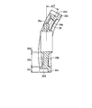
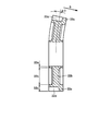
- FIG. 5 is a cross-sectional view showing deformation at the time of meshing of helical gears corresponding to the view taken along the line VV in FIG. 3. It is a front view which shows the helical gear in background art.
- FIG. 13 is a cross-sectional view taken along line XIII-XIII in FIG. It is a front view which shows the deformation
- FIG. 15 is a cross-sectional view taken along line XV-XV in FIG. 14.
- each component is not necessarily essential for the present invention unless otherwise specified.
- the above number is an example, and the scope of the present invention is not necessarily limited to the number, amount, etc.
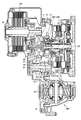
- FIG. 1 is a cross-sectional view showing a configuration of a transaxle in which a transmission and an axle including a gear device employing a helical gear according to the present embodiment are integrally formed.
- the transmission shown in FIG. 1 is a transmission used for a front-wheel drive hybrid vehicle.
- the transaxle includes rotating electric machines 100 and 200, a planetary gear 300 for power distribution, and a differential mechanism 400.
- Rotating electric machines 100 and 200, planetary gear 300, and differential mechanism 400 are provided in the housing.
- Rotating electric machine 100 includes a rotating shaft 10 as a first axis provided so as to be rotatable with respect to a housing.
- the rotating electrical machine 200 includes a rotating shaft 20 as a second shaft that is provided so as to be rotatable with respect to the housing.
- Rotating electric machines 100 and 200 have a stator core formed by stacking electromagnetic steel plates and a stator coil wound around the stator core. The terminal of the stator coil is connected to the power supply cable from the external power source, and the external power source and the stator coil are electrically connected.
- the planetary gear 300 is connected to the rotary shaft 20.
- the planetary gear 300 divides and transmits engine power transmitted via the rotary shaft 20 to the rotary shaft 10 and the rotary shaft 30 as the third axis.
- the differential mechanism 400 includes a final driven gear 91.
- the final driven gear 91 is connected to the rotary shaft 30 with a final drive gear 81 interposed therebetween.
- the differential unit 90 that receives power transmission from the rotary shaft 30 transmits equal driving force to both wheels while changing the rotational speed of the left and right wheels when the vehicle is turning.
- the transaxle shown in FIG. 1 functions as a power transmission device that transmits the rotational driving force input from the motor and the crankshaft of the engine to the driving wheel and outputs it.
- a three-shaft gear device in which one gear has two meshing positions is provided in a transmission that outputs motor power and engine power. It has been adopted.
- the rotary shaft 10 is provided with a first gear 11.
- a second gear 21 is provided on the rotary shaft 20.
- a third gear 31 is provided on the rotary shaft 30.
- Helical gears are used for the first gear 11, the second gear 21, and the third gear 31, respectively.
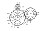
- the meshing state of the three-shaft gear device is shown.
- the first gear 11 and the second gear 21 are engaged at an engagement point 41.
- the second gear 21 and the third gear 31 are meshed at a meshing point 42.
- the power transmission device includes a gear device including the first gear 11, the second gear 21, and the third gear 31.
- the meshing point 41 is a meshing position between the first gear 11 and the second gear 21.
- the meshing point 42 is a meshing position between the second gear 21 and the third gear 31.
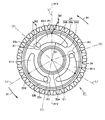
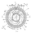
- FIGS. 3 is a front view showing the helical gear 21 of the present embodiment
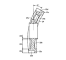
- FIG. 4 is a partially enlarged plan view of the helical gear 21 of the present embodiment
- FIG. It is sectional drawing which shows the deformation
- the helical gears used in the first gear 11 and the third gear 31 may be the same helical gear as in the present embodiment.
- the helical gear 21 includes a hub portion 22a attached to the rotary shaft 20, a disk portion 22b extending from the hub portion 22a toward the outer side in the radial direction of the rotary shaft 20, and a rim provided outside the disk portion 22b. Part 22c.
- the rim portion 22c includes a plurality of teeth 22d on the outer peripheral surface thereof.
- the disk portion 22b includes an opening peripheral wall 24 that defines a through hole H11 provided along the periphery of the hub portion 22a.
- the opening peripheral wall 24 is provided at three locations with a 120 ° pitch.
- the opening peripheral wall 24 in the present embodiment includes an inner peripheral side surface 24a positioned on the hub portion 22a side, an outer peripheral side surface 24b positioned closer to the rim portion 22c than the inner peripheral side surface 24a, one end of the inner peripheral side surface 24a, and an outer peripheral side surface. It includes a first end side surface 24c that connects one end of 24b, and a second end side surface 24d that connects the other end of the inner peripheral side surface 24a and the other end of the outer peripheral side surface 24b.
- the inner peripheral side surface 24a is formed of a part of an arc having a radius (D1) centered on the rotation center (also the center of the hub portion 22a) C1 of the rotary shaft 20.
- the first end side surface 24c and the second end side surface 24d are formed of a semicircle having a radius (D2) centered on the rotation center C2.
- the outer peripheral side surface 24b is surrounded by the most distal end side (A1 in the drawing) in the rotational direction (R1) of the helical gear 21 at the radial distance of the rotating shaft from the hub portion 22a side of the rim portion 22c to the outer peripheral side surface 24b.
- the first side surface region 24b1 has a curved shape that protrudes toward the rim portion 22c.
- the outer peripheral side surface 24b in the present embodiment has a second side surface region 24b2 located on the rear end side of the helical gear 21 in the rotational direction (R1) relative to the first side surface region 24b1.
- the second side surface region 24b2 is provided continuously with the first side surface region 24b1 and the connecting portion P1, and the first side surface region 24b1 and the second side surface region 24b2 are provided symmetrically with the connecting portion (P1) in between. ing. Therefore, the through hole H11 defined by the opening peripheral wall 24 has a bilaterally symmetric form with respect to an imaginary straight line (L1) connecting the rotation center C1 and the connecting portion (P1).
- FIGS. 6 is a front view showing a helical gear 21Y in the background art
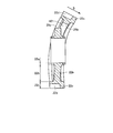
- FIG. 7 is a cross-sectional view showing deformation at the time of meshing of the helical gear 21Y corresponding to the arrow VII-VII in FIG. is there.
- the basic shape of the helical gear 21 in the present embodiment shown in FIG. 3 and the helical gear 21Y in the background art are the same, and the opening peripheral wall 25 that defines the through hole H21 provided in the disk portion 22b.
- the shape is different.
- the opening peripheral wall 25 includes an inner peripheral side surface 25a positioned on the hub portion 22a side, an outer peripheral side surface 25b positioned closer to the rim portion 22c than the inner peripheral side surface 25a, and one end and an outer periphery of the inner peripheral side surface 25a. It includes a first end side surface 25c that connects one end of the side surface 25b, and a second end side surface 25d that connects the other end of the inner peripheral side surface 25a and the other end of the outer peripheral side surface 25b.
- the inner peripheral side surface 25a is made of a part of an arc having a radius (D11) centered on the rotation center C1 of the rotary shaft 20.
- the outer peripheral side surface 25b is formed of a part of an arc having a radius (D12: D12> D11) centered on the rotation center C1 of the rotary shaft 20.
- the first end side surface 25c and the second end side surface 25d are formed of a semicircle having a radius (D2) centered on the rotation center C2.
- the outer peripheral side surface 25b is provided symmetrically across the connecting portion (P1). Therefore, the through hole H21 defined by the opening peripheral wall 25 has a bilaterally symmetric form with respect to an imaginary straight line (L1) connecting the rotation center C1 and the connecting portion (P1).
- the rotation direction (R1) of the helical gear 21Y is determined at a radial distance of the rotation shaft.
- the tilt angle ( ⁇ 1) of the helical gear 21 in the present embodiment is larger than the tilt angle ( ⁇ 3) of the helical gear 21Z in which the through hole is not provided in the disk portion 22b shown in FIG. large. That is, the relationship of the inclination angle ( ⁇ 2) of the helical gear 21Y> the inclination angle ( ⁇ 1) of the helical gear 21> the inclination angle ( ⁇ 3) of the helical gear 21Z.
- FIG. 8 shows the relationship between the through-hole phase and the stress in the helical gear 21 of the present embodiment
- FIG. 9 shows the relationship between the through-hole phase and the stress in the helical gear 21Y in the background art.
- (1) in each figure shows the position of the most distal end side in the rotational direction (R1) of the helical gear 21 at the position of the through hole shown in FIGS. 8 and 9, the tooth width end portion LH means the position of the tooth on the left side (back side in the figure) when viewed from the rotation direction, and the center of the tooth width is the center tooth as viewed from the rotation direction.
- the tooth width end portion RH means the position of the tooth on the right side (front side in the figure) as viewed from the rotation direction.
- the stress in the through-hole phase of the helical gear 21Y in the background art is the position of the through-hole indicated by (1) in the position of the most distal end in the rotational direction (R1) of the helical gear 21. Position), a stress exceeding 700 MPa was generated.
- the stress in the through-hole phase of the helical gear 21 in the present embodiment is the most distal position in the rotational direction (R1) of the helical gear 21 (the position of the through-hole indicated by (1)).
- the stress can be reduced to a stress not exceeding 700 Mpa.
- the radius of the rotation shaft from the hub portion 22a side of the rim portion 22c to the outer peripheral side surface 24b is changed by changing the curvature of the first side region 24b1 from the rotation center C2 when the through hole is viewed along the rotation direction.
- the distance (W2) of the position at the most distal end side in the rotation direction (R1) of the helical gear 21 of the first side surface region 24b1 is provided to be the largest.
- the helical gear according to the present embodiment vibration and noise can be suppressed, and stress generated on the front end side in the rotation direction of the through hole provided in the disk portion can be reduced. As a result, it is possible to improve the performance of the gear device employing the helical gear and the transaxle including the gear device.
- the outer peripheral side surface 24b is provided symmetrically with respect to the connecting portion P1. This is because the same effect can be obtained even when the helical gear rotates in the reverse direction. Moreover, although the case where the 1st side surface area
- a helical gear 21A having an opening peripheral wall 25A that defines a through hole H12 as shown in FIG. 10 may be employed. Note that the difference between the helical gear 21A and the helical gear 21 shown in FIG. 3 is the difference in the shape of the opening peripheral wall. Therefore, the same or corresponding parts are denoted by the same reference numerals, and overlapping descriptions are omitted. Do not repeat.
- the opening peripheral wall 25A is provided at three positions with a 120 ° pitch.
- the opening peripheral wall 25A includes a first opening peripheral wall 25R positioned on the front end side in the rotation direction of the helical gear 21A and a second opening peripheral wall 25L positioned on the rear end side in the rotation direction of the helical gear 21A.
- the first opening peripheral wall 25R and the second opening peripheral wall 25L are connected at the connecting portion (P1).
- the first opening peripheral wall 25R includes a first inner peripheral side surface 25a1 positioned on the hub portion 22a side, a first outer peripheral side surface 25b1 positioned closer to the rim portion 22c than the first inner peripheral side surface 25a1, and a first inner peripheral side surface 25a1. And a first end side surface 25c1 that connects one end of the first outer peripheral side surface 25b1.
- the second opening peripheral wall 25L includes a second inner peripheral side surface 25a2 positioned on the hub portion 22a side, a second outer peripheral side surface 25b2 positioned on the rim portion 22c side with respect to the second inner peripheral side surface 25a2, and a second inner peripheral side surface 25a2. And a second end side surface 25c2 connecting the one end of the second outer peripheral side surface 25b2.
- the second inner peripheral side surface 25a2 is formed of a part of an arc having a radius (D11) centered on the rotation center C1 of the rotary shaft 20. Further, the second outer peripheral side surface 25b2 is formed of a part of an arc having a radius (D21: D21> D11) centered on the rotation center C1 of the rotary shaft 20.
- the first end side surface 25c1 and the second end side surface 25c2 are formed of a semicircle having a radius (D2) centered on the rotation center C2.
- the first outer peripheral side surface 25b1 is the most distal side in the rotational direction (R1) of the helical gear 21 at the radial distance of the rotating shaft from the hub portion 22a side of the rim portion 22c to the first outer peripheral side surface 25b1 (in the drawing). In the region surrounded by A1, the distance (W2) located on the side closest to the line (1) is larger than the distance (W1) of the connecting portion (P1) on the rear end side.
- the first outer peripheral side surface 25b1 is linear.
- the first inner peripheral side surface 25a1 is provided substantially parallel to the first outer peripheral side surface 25b1, and the first inner peripheral side surface 25a1 is also linear.
- both the helical gear 21 shown in FIG. 3 and the helical gear 21A shown in FIG. 10 have opening peripheral walls provided at three locations at a 120 ° pitch, but the number is limited to this. is not.
- the present invention can be applied particularly advantageously to gear devices such as vehicle transmissions and transfers.
Landscapes
- Engineering & Computer Science (AREA)
- General Engineering & Computer Science (AREA)
- Mechanical Engineering (AREA)
- Gears, Cams (AREA)
- Gear Transmission (AREA)
Abstract
Description
他の形態においては、上記第1側面領域は、直線形状に設けられている。
はすば歯車21Yにおいて開口周壁25は、ハブ部22a側に位置する内周側面25aと、内周側面25aよりもリム部22c側に位置する外周側面25bと、内周側面25aの一端と外周側面25bの一端とを連結する第1端部側面25cと、内周側面25aの他端と外周側面25bの他端を連結する第2端部側面25dとを含む。
また、他の実施の形態として、図10に示すような貫通孔H12を規定する開口周壁25Aを有するはすば歯車21Aを採用することも可能である。なお、このはすば歯車21Aと図3に示すはすば歯車21との相違は、開口周壁の形状の相違にあるため、同一または相当部分は同一の参照番号を付し、重複する説明は繰り返さない。
Claims (5)
- [規則91に基づく訂正 15.12.2011]
回転軸に装着されるハブ部(22a)と、前記ハブ部(22a)から前記回転軸の半径方向外側に向かって延びるディスク部(22b)と、前記ディスク部(22b)の外側に設けられたリム部(22c)とを備える、はすば歯車(21)であって、
前記リム部(22c)は、その外周面に複数の歯(22d)を含み、
前記ディスク部(22b)は、前記ハブ部(22a)の周りに沿って設けられる貫通孔(H11)を規定する複数の開口周壁(24)を含み、
前記開口周壁(24)は、
前記ハブ部(22a)側に位置する内周側面(24a)と、
前記内周側面(24a)よりも前記リム部(22c)側に位置する外周側面(24b)と、
前記内周側面(24a)の一端と前記外周側面(24b)の一端を連結する第1端部側面(24c)と、
前記内周側面(24a)の他端と前記外周側面(24b)の他端を連結する第2端部側面(24d)と、を含み、
前記外周側面(24b)は、第1側面領域(24b1)と、前記第1側面領域(24b1)よりも当該はすば歯車(21)の回転方向(R1)の後端側に位置する第2側面領域(24b2)とを有し、
前記第1側面領域(24b1)は、前記リム部(22c)の前記ハブ部(22a)側から前記外周側面(24b)までの前記回転軸の前記半径方向の距離において、当該はすば歯車(21)の回転方向(R1)の最も先端側の位置における距離(W2)が、最も大きく設けられている、はすば歯車。 - 前記第1側面領域(24b1)と前記第2側面領域(24b2)とは連結部(P1)により連続して設けられ、
前記第1側面領域(24b1)と前記第2側面領域(24b2)とは前記連結部(P1)を挟んで左右対称に設けられている、請求項1に記載のはすば歯車。 - 前記第1側面領域(24b1)は、湾曲形状に設けられている、請求項1または2に記載のはすば歯車。
- 前記第1側面領域(24b1)は、直線形状に設けられている、請求項1または2に記載のはすば歯車。
- 請求項1に記載のはすば歯車を備える、動力伝達装置。
Priority Applications (4)
| Application Number | Priority Date | Filing Date | Title |
|---|---|---|---|
| CN201180003604.6A CN103608611B (zh) | 2011-06-23 | 2011-06-23 | 斜齿轮以及动力传递装置 |
| US13/391,176 US8733198B2 (en) | 2011-06-23 | 2011-06-23 | Helical gear and power transmission apparatus |
| JP2012506017A JP5252121B1 (ja) | 2011-06-23 | 2011-06-23 | はすば歯車および動力伝達装置 |
| PCT/JP2011/064412 WO2012176304A1 (ja) | 2011-06-23 | 2011-06-23 | はすば歯車および動力伝達装置 |
Applications Claiming Priority (1)
| Application Number | Priority Date | Filing Date | Title |
|---|---|---|---|
| PCT/JP2011/064412 WO2012176304A1 (ja) | 2011-06-23 | 2011-06-23 | はすば歯車および動力伝達装置 |
Publications (1)
| Publication Number | Publication Date |
|---|---|
| WO2012176304A1 true WO2012176304A1 (ja) | 2012-12-27 |
Family
ID=47360561
Family Applications (1)
| Application Number | Title | Priority Date | Filing Date |
|---|---|---|---|
| PCT/JP2011/064412 Ceased WO2012176304A1 (ja) | 2011-06-23 | 2011-06-23 | はすば歯車および動力伝達装置 |
Country Status (4)
| Country | Link |
|---|---|
| US (1) | US8733198B2 (ja) |
| JP (1) | JP5252121B1 (ja) |
| CN (1) | CN103608611B (ja) |
| WO (1) | WO2012176304A1 (ja) |
Cited By (1)
| Publication number | Priority date | Publication date | Assignee | Title |
|---|---|---|---|---|
| US9955991B2 (en) | 2009-06-16 | 2018-05-01 | Frii S.A. | Device for endoscopic resection or removal of tissue |
Families Citing this family (5)
| Publication number | Priority date | Publication date | Assignee | Title |
|---|---|---|---|---|
| JP5240405B1 (ja) * | 2011-09-14 | 2013-07-17 | トヨタ自動車株式会社 | はすば歯車および動力伝達装置 |
| JP6555210B2 (ja) * | 2016-08-09 | 2019-08-07 | トヨタ自動車株式会社 | 歯車機構およびその製造方法 |
| IT201800003230A1 (it) | 2018-03-02 | 2019-09-02 | Ge Avio Srl | Ingranaggio non-assialsimmetrico |
| JP7035953B2 (ja) * | 2018-10-17 | 2022-03-15 | トヨタ自動車株式会社 | 車両用ギヤ |
| CN111828591B (zh) * | 2020-06-11 | 2022-05-17 | 重庆大学 | 一种新型智能齿轮 |
Citations (5)
| Publication number | Priority date | Publication date | Assignee | Title |
|---|---|---|---|---|
| JPH04327056A (ja) * | 1991-04-25 | 1992-11-16 | Isuzu Motors Ltd | 低騒音ギア及びその製造方法 |
| JPH08121574A (ja) * | 1994-10-25 | 1996-05-14 | Minolta Co Ltd | 消音歯車及びその成形方法 |
| JP2005069401A (ja) * | 2003-08-26 | 2005-03-17 | Toyota Motor Corp | はすば歯車 |
| JP2009216153A (ja) * | 2008-03-10 | 2009-09-24 | Toyota Motor Corp | 歯車 |
| JP2009228741A (ja) * | 2008-03-21 | 2009-10-08 | Toyota Motor Corp | 歯車装置および動力伝達装置 |
Family Cites Families (10)
| Publication number | Priority date | Publication date | Assignee | Title |
|---|---|---|---|---|
| US1163926A (en) * | 1914-11-30 | 1915-12-14 | Harrison L Hudson | Gear. |
| US1163925A (en) * | 1914-11-30 | 1915-12-14 | Harrison L Hudson | Gear. |
| GB932015A (en) * | 1959-06-12 | 1963-07-24 | Lear Inc | Anti-backlash gear wheel combination |
| US5347880A (en) * | 1992-11-23 | 1994-09-20 | Harnischfeger Corporation | Method and apparatus for servicing a gear assembly |
| US5852951A (en) * | 1994-10-04 | 1998-12-29 | Briggs & Stratton Corporation | Composite gear and method of making same |
| US5657666A (en) | 1994-10-25 | 1997-08-19 | Minolta Co., Ltd. | Transmission mechanism capable of suppressing vibrational noise |
| DE10222132B4 (de) * | 2002-05-17 | 2006-04-20 | SCHWäBISCHE HüTTENWERKE GMBH | Mehrfach schrägverzahntes, einteilig gepresstes Zahnrad sowie Verfahren und Vorrichtung zu seiner Herstellung |
| JP4498816B2 (ja) | 2004-05-12 | 2010-07-07 | ナブテスコ株式会社 | 偏心揺動型遊星歯車装置 |
| JP2008303968A (ja) | 2007-06-07 | 2008-12-18 | Toyota Industries Corp | 歯車伝達機構 |
| JP5203130B2 (ja) | 2008-10-21 | 2013-06-05 | 株式会社豊田中央研究所 | ドライブプレートの連結構造 |
-
2011
- 2011-06-23 WO PCT/JP2011/064412 patent/WO2012176304A1/ja not_active Ceased
- 2011-06-23 US US13/391,176 patent/US8733198B2/en active Active
- 2011-06-23 CN CN201180003604.6A patent/CN103608611B/zh active Active
- 2011-06-23 JP JP2012506017A patent/JP5252121B1/ja active Active
Patent Citations (5)
| Publication number | Priority date | Publication date | Assignee | Title |
|---|---|---|---|---|
| JPH04327056A (ja) * | 1991-04-25 | 1992-11-16 | Isuzu Motors Ltd | 低騒音ギア及びその製造方法 |
| JPH08121574A (ja) * | 1994-10-25 | 1996-05-14 | Minolta Co Ltd | 消音歯車及びその成形方法 |
| JP2005069401A (ja) * | 2003-08-26 | 2005-03-17 | Toyota Motor Corp | はすば歯車 |
| JP2009216153A (ja) * | 2008-03-10 | 2009-09-24 | Toyota Motor Corp | 歯車 |
| JP2009228741A (ja) * | 2008-03-21 | 2009-10-08 | Toyota Motor Corp | 歯車装置および動力伝達装置 |
Cited By (1)
| Publication number | Priority date | Publication date | Assignee | Title |
|---|---|---|---|---|
| US9955991B2 (en) | 2009-06-16 | 2018-05-01 | Frii S.A. | Device for endoscopic resection or removal of tissue |
Also Published As
| Publication number | Publication date |
|---|---|
| CN103608611B (zh) | 2016-06-08 |
| US20120325037A1 (en) | 2012-12-27 |
| JP5252121B1 (ja) | 2013-07-31 |
| CN103608611A (zh) | 2014-02-26 |
| JPWO2012176304A1 (ja) | 2015-02-23 |
| US8733198B2 (en) | 2014-05-27 |
Similar Documents
| Publication | Publication Date | Title |
|---|---|---|
| JP5240405B1 (ja) | はすば歯車および動力伝達装置 | |
| JP5252121B1 (ja) | はすば歯車および動力伝達装置 | |
| JP4975081B2 (ja) | 遊星歯車減速装置 | |
| JP6222164B2 (ja) | 車両の動力伝達構造 | |
| JP2011038546A (ja) | デファレンシャル装置 | |
| US7753821B2 (en) | Power transmission device | |
| CN106132748A (zh) | 车辆用驱动装置 | |
| CN103429932A (zh) | 车辆的啮合齿轮 | |
| JP2015230052A (ja) | 遊星歯車機構 | |
| JP2010181012A (ja) | プラネタリキャリア | |
| JP4379525B2 (ja) | 歯車装置および動力伝達装置 | |
| EP3640502B1 (en) | Vehicle gear | |
| CN107709811A (zh) | 带有扭转减振器的变速器 | |
| JP2011247348A (ja) | 車両の噛合歯車 | |
| JP6447447B2 (ja) | ギヤ装置 | |
| JP2019007603A (ja) | 遊星歯車機構を用いた変速装置、伝動装置、電動作業車両 | |
| JP5626467B2 (ja) | 車両用動力伝達装置の遊星歯車装置 | |
| JP2019082184A (ja) | スプライン構造 | |
| CN220910381U (zh) | 差速器、动力系统及车辆 | |
| JP2017110741A (ja) | 車両の動力伝達装置 | |
| JP6101426B2 (ja) | ハイポイド歯車装置 | |
| JP2013124742A (ja) | 車両用歯車装置の歯打ち音防止装置 | |
| JP2019210970A (ja) | 動力伝達装置 | |
| JP6384407B2 (ja) | 最終減速装置のダンパ配設構造 | |
| JP2012237405A (ja) | 歯車 |
Legal Events
| Date | Code | Title | Description |
|---|---|---|---|
| ENP | Entry into the national phase |
Ref document number: 2012506017 Country of ref document: JP Kind code of ref document: A |
|
| WWE | Wipo information: entry into national phase |
Ref document number: 13391176 Country of ref document: US |
|
| 121 | Ep: the epo has been informed by wipo that ep was designated in this application |
Ref document number: 11868052 Country of ref document: EP Kind code of ref document: A1 |
|
| NENP | Non-entry into the national phase |
Ref country code: DE |
|
| 122 | Ep: pct application non-entry in european phase |
Ref document number: 11868052 Country of ref document: EP Kind code of ref document: A1 |