WO2012176272A1 - 二次電池の製造方法 - Google Patents
二次電池の製造方法 Download PDFInfo
- Publication number
- WO2012176272A1 WO2012176272A1 PCT/JP2011/064075 JP2011064075W WO2012176272A1 WO 2012176272 A1 WO2012176272 A1 WO 2012176272A1 JP 2011064075 W JP2011064075 W JP 2011064075W WO 2012176272 A1 WO2012176272 A1 WO 2012176272A1
- Authority
- WO
- WIPO (PCT)
- Prior art keywords
- negative electrode
- positive electrode
- mixture layer
- sheet
- cell case
- Prior art date
- Legal status (The legal status is an assumption and is not a legal conclusion. Google has not performed a legal analysis and makes no representation as to the accuracy of the status listed.)
- Ceased
Links
Images




Classifications
-
- H—ELECTRICITY
- H01—ELECTRIC ELEMENTS
- H01M—PROCESSES OR MEANS, e.g. BATTERIES, FOR THE DIRECT CONVERSION OF CHEMICAL ENERGY INTO ELECTRICAL ENERGY
- H01M10/00—Secondary cells; Manufacture thereof
- H01M10/05—Accumulators with non-aqueous electrolyte
- H01M10/056—Accumulators with non-aqueous electrolyte characterised by the materials used as electrolytes, e.g. mixed inorganic/organic electrolytes
- H01M10/0564—Accumulators with non-aqueous electrolyte characterised by the materials used as electrolytes, e.g. mixed inorganic/organic electrolytes the electrolyte being constituted of organic materials only
- H01M10/0566—Liquid materials
-
- H—ELECTRICITY
- H01—ELECTRIC ELEMENTS
- H01M—PROCESSES OR MEANS, e.g. BATTERIES, FOR THE DIRECT CONVERSION OF CHEMICAL ENERGY INTO ELECTRICAL ENERGY
- H01M10/00—Secondary cells; Manufacture thereof
- H01M10/04—Construction or manufacture in general
- H01M10/0481—Compression means other than compression means for stacks of electrodes and separators
-
- H—ELECTRICITY
- H01—ELECTRIC ELEMENTS
- H01M—PROCESSES OR MEANS, e.g. BATTERIES, FOR THE DIRECT CONVERSION OF CHEMICAL ENERGY INTO ELECTRICAL ENERGY
- H01M10/00—Secondary cells; Manufacture thereof
- H01M10/05—Accumulators with non-aqueous electrolyte
- H01M10/058—Construction or manufacture
-
- H—ELECTRICITY
- H01—ELECTRIC ELEMENTS
- H01M—PROCESSES OR MEANS, e.g. BATTERIES, FOR THE DIRECT CONVERSION OF CHEMICAL ENERGY INTO ELECTRICAL ENERGY
- H01M10/00—Secondary cells; Manufacture thereof
- H01M10/24—Alkaline accumulators
- H01M10/28—Construction or manufacture
-
- H—ELECTRICITY
- H01—ELECTRIC ELEMENTS
- H01M—PROCESSES OR MEANS, e.g. BATTERIES, FOR THE DIRECT CONVERSION OF CHEMICAL ENERGY INTO ELECTRICAL ENERGY
- H01M50/00—Constructional details or processes of manufacture of the non-active parts of electrochemical cells other than fuel cells, e.g. hybrid cells
- H01M50/20—Mountings; Secondary casings or frames; Racks, modules or packs; Suspension devices; Shock absorbers; Transport or carrying devices; Holders
- H01M50/204—Racks, modules or packs for multiple batteries or multiple cells
- H01M50/207—Racks, modules or packs for multiple batteries or multiple cells characterised by their shape
- H01M50/209—Racks, modules or packs for multiple batteries or multiple cells characterised by their shape adapted for prismatic or rectangular cells
-
- H—ELECTRICITY
- H01—ELECTRIC ELEMENTS
- H01M—PROCESSES OR MEANS, e.g. BATTERIES, FOR THE DIRECT CONVERSION OF CHEMICAL ENERGY INTO ELECTRICAL ENERGY
- H01M50/00—Constructional details or processes of manufacture of the non-active parts of electrochemical cells other than fuel cells, e.g. hybrid cells
- H01M50/20—Mountings; Secondary casings or frames; Racks, modules or packs; Suspension devices; Shock absorbers; Transport or carrying devices; Holders
- H01M50/262—Mountings; Secondary casings or frames; Racks, modules or packs; Suspension devices; Shock absorbers; Transport or carrying devices; Holders with fastening means, e.g. locks
- H01M50/264—Mountings; Secondary casings or frames; Racks, modules or packs; Suspension devices; Shock absorbers; Transport or carrying devices; Holders with fastening means, e.g. locks for cells or batteries, e.g. straps, tie rods or peripheral frames
-
- H—ELECTRICITY
- H01—ELECTRIC ELEMENTS
- H01M—PROCESSES OR MEANS, e.g. BATTERIES, FOR THE DIRECT CONVERSION OF CHEMICAL ENERGY INTO ELECTRICAL ENERGY
- H01M50/00—Constructional details or processes of manufacture of the non-active parts of electrochemical cells other than fuel cells, e.g. hybrid cells
- H01M50/60—Arrangements or processes for filling or topping-up with liquids; Arrangements or processes for draining liquids from casings
- H01M50/609—Arrangements or processes for filling with liquid, e.g. electrolytes
-
- H—ELECTRICITY
- H01—ELECTRIC ELEMENTS
- H01M—PROCESSES OR MEANS, e.g. BATTERIES, FOR THE DIRECT CONVERSION OF CHEMICAL ENERGY INTO ELECTRICAL ENERGY
- H01M10/00—Secondary cells; Manufacture thereof
- H01M10/05—Accumulators with non-aqueous electrolyte
- H01M10/052—Li-accumulators
-
- H—ELECTRICITY
- H01—ELECTRIC ELEMENTS
- H01M—PROCESSES OR MEANS, e.g. BATTERIES, FOR THE DIRECT CONVERSION OF CHEMICAL ENERGY INTO ELECTRICAL ENERGY
- H01M10/00—Secondary cells; Manufacture thereof
- H01M10/60—Heating or cooling; Temperature control
- H01M10/61—Types of temperature control
- H01M10/613—Cooling or keeping cold
-
- H—ELECTRICITY
- H01—ELECTRIC ELEMENTS
- H01M—PROCESSES OR MEANS, e.g. BATTERIES, FOR THE DIRECT CONVERSION OF CHEMICAL ENERGY INTO ELECTRICAL ENERGY
- H01M10/00—Secondary cells; Manufacture thereof
- H01M10/60—Heating or cooling; Temperature control
- H01M10/62—Heating or cooling; Temperature control specially adapted for specific applications
- H01M10/625—Vehicles
-
- H—ELECTRICITY
- H01—ELECTRIC ELEMENTS
- H01M—PROCESSES OR MEANS, e.g. BATTERIES, FOR THE DIRECT CONVERSION OF CHEMICAL ENERGY INTO ELECTRICAL ENERGY
- H01M10/00—Secondary cells; Manufacture thereof
- H01M10/60—Heating or cooling; Temperature control
- H01M10/64—Heating or cooling; Temperature control characterised by the shape of the cells
- H01M10/647—Prismatic or flat cells, e.g. pouch cells
-
- H—ELECTRICITY
- H01—ELECTRIC ELEMENTS
- H01M—PROCESSES OR MEANS, e.g. BATTERIES, FOR THE DIRECT CONVERSION OF CHEMICAL ENERGY INTO ELECTRICAL ENERGY
- H01M10/00—Secondary cells; Manufacture thereof
- H01M10/60—Heating or cooling; Temperature control
- H01M10/65—Means for temperature control structurally associated with the cells
- H01M10/655—Solid structures for heat exchange or heat conduction
- H01M10/6554—Rods or plates
- H01M10/6555—Rods or plates arranged between the cells
-
- H—ELECTRICITY
- H01—ELECTRIC ELEMENTS
- H01M—PROCESSES OR MEANS, e.g. BATTERIES, FOR THE DIRECT CONVERSION OF CHEMICAL ENERGY INTO ELECTRICAL ENERGY
- H01M10/00—Secondary cells; Manufacture thereof
- H01M10/60—Heating or cooling; Temperature control
- H01M10/65—Means for temperature control structurally associated with the cells
- H01M10/655—Solid structures for heat exchange or heat conduction
- H01M10/6556—Solid parts with flow channel passages or pipes for heat exchange
- H01M10/6557—Solid parts with flow channel passages or pipes for heat exchange arranged between the cells
-
- H—ELECTRICITY
- H01—ELECTRIC ELEMENTS
- H01M—PROCESSES OR MEANS, e.g. BATTERIES, FOR THE DIRECT CONVERSION OF CHEMICAL ENERGY INTO ELECTRICAL ENERGY
- H01M2220/00—Batteries for particular applications
- H01M2220/20—Batteries in motive systems, e.g. vehicle, ship, plane
-
- Y—GENERAL TAGGING OF NEW TECHNOLOGICAL DEVELOPMENTS; GENERAL TAGGING OF CROSS-SECTIONAL TECHNOLOGIES SPANNING OVER SEVERAL SECTIONS OF THE IPC; TECHNICAL SUBJECTS COVERED BY FORMER USPC CROSS-REFERENCE ART COLLECTIONS [XRACs] AND DIGESTS
- Y02—TECHNOLOGIES OR APPLICATIONS FOR MITIGATION OR ADAPTATION AGAINST CLIMATE CHANGE
- Y02E—REDUCTION OF GREENHOUSE GAS [GHG] EMISSIONS, RELATED TO ENERGY GENERATION, TRANSMISSION OR DISTRIBUTION
- Y02E60/00—Enabling technologies; Technologies with a potential or indirect contribution to GHG emissions mitigation
- Y02E60/10—Energy storage using batteries
-
- Y—GENERAL TAGGING OF NEW TECHNOLOGICAL DEVELOPMENTS; GENERAL TAGGING OF CROSS-SECTIONAL TECHNOLOGIES SPANNING OVER SEVERAL SECTIONS OF THE IPC; TECHNICAL SUBJECTS COVERED BY FORMER USPC CROSS-REFERENCE ART COLLECTIONS [XRACs] AND DIGESTS
- Y02—TECHNOLOGIES OR APPLICATIONS FOR MITIGATION OR ADAPTATION AGAINST CLIMATE CHANGE
- Y02P—CLIMATE CHANGE MITIGATION TECHNOLOGIES IN THE PRODUCTION OR PROCESSING OF GOODS
- Y02P70/00—Climate change mitigation technologies in the production process for final industrial or consumer products
- Y02P70/50—Manufacturing or production processes characterised by the final manufactured product
-
- Y—GENERAL TAGGING OF NEW TECHNOLOGICAL DEVELOPMENTS; GENERAL TAGGING OF CROSS-SECTIONAL TECHNOLOGIES SPANNING OVER SEVERAL SECTIONS OF THE IPC; TECHNICAL SUBJECTS COVERED BY FORMER USPC CROSS-REFERENCE ART COLLECTIONS [XRACs] AND DIGESTS
- Y10—TECHNICAL SUBJECTS COVERED BY FORMER USPC
- Y10T—TECHNICAL SUBJECTS COVERED BY FORMER US CLASSIFICATION
- Y10T29/00—Metal working
- Y10T29/49—Method of mechanical manufacture
- Y10T29/49002—Electrical device making
- Y10T29/49108—Electric battery cell making
Definitions
- the present invention relates to a method for manufacturing a secondary battery.
- it is related with the manufacturing method of the battery provided with the winding electrode body wound by flat shape.
- Lithium-ion secondary batteries, nickel-metal hydride batteries, and other secondary batteries are important as, for example, power sources mounted on vehicles that use electricity as a drive source, or power sources used in personal computers, portable terminals, and other electrical products It is growing.
- a lithium ion secondary battery that is lightweight and obtains a high energy density is preferable as a high-output power source mounted on a vehicle.
- a flat wound electrode body obtained by winding and pressing a positive electrode sheet and a negative electrode sheet with a separator sheet interposed therebetween is provided. It is housed in a rectangular battery case (typically a flat box-shaped case) together with a non-aqueous electrolyte.
- a non-aqueous electrolyte is a medium that conducts charge carriers (typically cations such as lithium ions) during charge and discharge of a secondary battery, and when the amount of non-aqueous electrolyte injected into the battery case is not appropriate Various battery characteristics cannot be exhibited sufficiently.
- the electrolyte is depleted (so-called “wither”) by repeatedly performing charge and discharge, and the battery resistance may increase and the output may decrease.
- Patent Documents 1 to 5 are listed as technical documents relating to the amount of electrolyte injected into the secondary battery.
- Patent Document 1 describes a technique for determining an injection amount of an electrolytic solution based on an opposing area of positive and negative electrodes.
- the wound electrode body accommodated in the battery case may be deformed and the output of the secondary battery may be lowered. Measures are taken to prevent deformation of the rotating electrode body.
- a non-aqueous electrolyte is injected into a battery case during the production of a secondary battery and the wound electrode body is impregnated with the non-aqueous electrolyte, the electrode body swells (expands) and the volume increases.
- the amount of the non-aqueous electrolyte impregnated inside the electrode body particularly the amount of the electrolyte present between the positive electrode sheet and the negative electrode sheet, varies depending on the degree of binding of the battery case.
- the present invention has been created to solve the above-described conventional problems, and its purpose is to determine an appropriate amount of the non-aqueous electrolyte to be injected into the cell case from the degree of binding of the cell case. Accordingly, it is an object of the present invention to provide a method for manufacturing a secondary battery having excellent battery characteristics, particularly cycle characteristics.
- the present invention provides a method of manufacturing a secondary battery. That is, the secondary battery manufacturing method disclosed herein is to prepare a long positive electrode sheet in which a positive electrode mixture layer is formed on a positive electrode current collector, and to form a negative electrode mixture layer on a negative electrode current collector. Preparing a long negative electrode sheet, forming a flat wound electrode body by winding and crushing the positive electrode sheet and the negative electrode sheet with a long separator sheet interposed therebetween, The wound electrode body is accommodated in a rectangular cell case having two wide surfaces corresponding to the flat surface of the wound electrode body, and the two wide surfaces facing each other are close to each other.
- BDSM Injecting a non-aqueous electrolyte solution into the case, including.
- Ap is the void amount [ml] of the positive electrode mixture layer.
- Bp is Tp 0 when the thickness of the positive electrode mixture layer before impregnating the non-aqueous electrolyte into the positive electrode mixture layer, and Tp 1 when the thickness of the positive electrode mixture layer after impregnation is It is a swelling rate determined by Tp 1 / Tp 0 .
- An is the void amount [ml] of the negative electrode mixture layer.
- Bn is, when the thickness of the negative electrode mixture layer before impregnating the non-aqueous electrolyte into the negative electrode mixture layer is Tn 0, and the thickness of the negative electrode mixture layer after impregnation is Tn 1 . It is a swelling rate determined by Tn 1 / Tn 0 .
- C is the void amount [ml] of the separator sheet.
- D is the total area [cm 2 ] of the surface where the positive electrode composite material layer and the negative electrode composite material layer face each other.
- E is the distance between the inner wall of the wide surface of the cell case before binding the cell case and the flat surface of the wound electrode body L 0, and the wide surface of the cell case after binding the cell case
- the facing is determined according to the binding rate [%] defined by (L 0 -L 1 ) / L 0 ⁇ 100
- This is the reference electrolyte amount [ml / cm 2 ] per unit area of the surface to be processed.
- the amount of the non-aqueous electrolyte impregnated in the positive electrode sheet, the negative electrode sheet, and the separator sheet is determined, and a wound electrode body formed by winding these sheets is provided.
- the amount of non-aqueous electrolyte X [ml] to be injected into the cell case is determined by determining the reference electrolyte amount existing between the sheets from the tightness rate of the accommodated cell case.
- the amount of the non-aqueous electrolyte determined by the above method is determined in consideration of the reference electrolyte amount determined according to the binding rate of the cell case.
- the cell in which the formed wound electrode body is accommodated An appropriate amount of non-aqueous electrolyte can be injected into the case. Therefore, according to such a method, the non-aqueous electrolyte injected into the cell case does not become insufficient or excessive, so that it is possible to manufacture a secondary battery with more excellent cycle characteristics.
- the value of E is 0.9 ⁇ 10 ⁇ 3 ml / It is determined within the range of cm 2 to 1.7 ⁇ 10 ⁇ 3 ml / cm 2 . According to this aspect, since the cell case is tightly bound at a tightness rate within the above range, even if the secondary battery is repeatedly charged and discharged, the deformation of the wound electrode body accommodated in the cell case is reduced and output. Can be prevented.
- a positive electrode sheet including a positive electrode mixture layer having a mixture density in which the value of Bp is in the range of 1.02 to 1.09 is used.
- a negative electrode sheet including a negative electrode mixture layer having a mixture density in which the value of Bn is in the range of 1.03 to 1.09 is used.
- the plurality of cell cases in which the wound electrode bodies are accommodated are arranged so that the wide surfaces of the cell cases face each other, and the plurality of cell cases The plurality of cell cases are tightly bound by applying a load in the arrangement direction, and the amount of non-aqueous electrolyte to be injected into each cell case is determined based on the tightness rate of each of the cell cases.
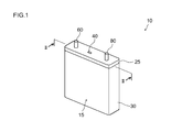
- FIG. 1 is a perspective view schematically showing an outer shape of a secondary battery according to an embodiment.
- 2 is a cross-sectional view taken along line II-II in FIG.
- FIG. 3 is a perspective view schematically showing the outer shape of the assembled battery according to the embodiment.
- FIG. 4 is an explanatory view schematically showing a method for obtaining the swelling ratio of the electrode mixture layer.
- FIG. 5 is an explanatory diagram schematically showing a method for obtaining the binding rate F of the secondary battery.
- FIG. 6 is a graph showing the relationship between the binding rate F and the reference electrolyte amount E.
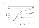
- FIG. 7 is a graph showing the relationship between the resistance ratio and the cycle number of the lithium ion secondary batteries according to Examples 1 to 4.
- FIG. 8 is a graph showing the relationship between the swelling ratio Bp of the lithium ion secondary batteries according to Examples 5 to 12 and the resistance ratio after the initial cycle.
- FIG. 9 is a graph showing the relationship between the swelling ratio Bn of the lithium ion secondary batteries according to Examples 13 to 20 and the resistance ratio after the initial cycle.
- FIG. 10 is a graph showing the relationship between the swelling rate Bn and the capacity retention rate of the lithium ion secondary batteries according to Examples 13 to 20.
- FIG. 11 is a side view schematically showing a vehicle (automobile) provided with the secondary battery according to the present invention.
- a method for producing a lithium ion secondary battery comprising an electrode having an electrode mixture layer formed on the surface of an electrode current collector.
- the present invention is not intended to be limited to such a battery.
- Ap is the void amount [ml] of the positive electrode mixture layer formed on the positive electrode sheet.
- the porosity Hp is, for example, the mass Wp of the positive electrode mixture layer, the apparent volume Vp of the positive electrode mixture layer, and the true density ⁇ p of the positive electrode mixture layer (mass depending on the actual volume not including voids).
- Hp [%] (1 ⁇ Wp / ⁇ p Vp) ⁇ 100.
- Bp is the swelling ratio when the positive electrode mixture layer is impregnated with the non-aqueous electrolyte.
- the swelling ratio Bp is defined as Tp 0 when the thickness of the positive electrode mixture layer 66 before impregnating the positive electrode mixture layer 66 with a non-aqueous electrolyte (for example, dimethyl carbonate not containing a lithium salt),
- a non-aqueous electrolyte for example, dimethyl carbonate not containing a lithium salt
- the “thickness of the composite material layer” means an average thickness and can be measured from a micrometer or a cross-sectional SEM (scanning electron microscope) photograph.
- the positive electrode sheet it is preferable to use a positive electrode sheet having an expansion coefficient Bp of 1.01 or more, or 1.02 or more, and 1.11 or less, or 1.09 or less.
- the swelling rate Bp can be adjusted by the pressing pressure when forming the positive electrode mixture layer.
- An is the void amount [ml] of the negative electrode mixture layer formed on the negative electrode sheet.
- the porosity Hn is, for example, the mass Wn of the negative electrode composite material layer, the apparent volume Vn of the negative electrode composite material layer, and the true density ⁇ n of the negative electrode composite material layer (mass based on the actual volume not including voids).
- Hn [%] (1 ⁇ Wn / ⁇ n Vn) ⁇ 100.
- Bn is the swelling ratio when the negative electrode mixture layer is impregnated with the nonaqueous electrolytic solution.
- the swelling ratio Bn is the same as the swelling ratio Bp of the positive electrode mixture layer described above, and the thickness of the negative electrode mixture layer before impregnating the nonaqueous electrolyte solution into the negative electrode mixture layer is Tn 0.
- Tn 1 / Tn 0 When the thickness of the negative electrode mixture layer after impregnating the negative electrode mixture layer with Tn 1 is defined as Tn 1 / Tn 0 .
- the negative electrode sheet it is preferable to use a negative electrode sheet having an expansion coefficient Bn of 1.03 or more, or 1.05 or more, and 1.13 or less and 1.09 or less.
- a negative electrode sheet of 1.03 to 1.09, preferably a negative electrode sheet of 1.05 to 1.09 is used.
- the swelling rate Bp can be adjusted by the pressing pressure when forming the negative electrode mixture layer.
- C is the void amount [ml] of the separator sheet.
- the porosity Hs is, for example, the mass Ws of the separator sheet, the apparent volume Vs of the separator sheet, and the true density ⁇ s of the separator sheet (value obtained by dividing the mass Ws by the actual volume not including the voids).
- Hs [%] (1 ⁇ Ws / ⁇ s Vs) ⁇ 100.
- the porosity of the separator sheet can be controlled by arbitrarily adjusting the amount of plasticizer used in the separator, the draw ratio, and the like. Note that the porosity Hp of the positive electrode sheet, the porosity Hn of the negative electrode sheet, and the porosity Hs of the separate sheet described above can also be calculated by a mercury intrusion method using a mercury porosimeter.
- D is the total area [cm 2 ] of the surface where the positive electrode mixture layer formed on the positive electrode sheet and the negative electrode mixture layer formed on the negative electrode sheet face each other. Typically, it is the total area [cm 2 ] of the positive electrode mixture layer formed on both surfaces (or one surface) of the sheet-like positive electrode current collector constituting the positive electrode sheet.
- E is a reference electrolyte amount [ml / cm 2 ] per unit area of the surface where the positive electrode composite material layer and the negative electrode composite material layer face each other. That is, non-water per unit area included in the gap between the positive electrode mixture layer and the negative electrode mixture layer (typically, the gap between the positive electrode mixture layer and the separator sheet and the gap between the separator sheet and the negative electrode mixture layer).
- the amount of electrolyte is determined according to the binding rate (degree of binding) F when the cell case is bound.
- “tighten” the cell case means a direction intersecting two wide surfaces facing each other across the internal space of the cell case (typically, a direction orthogonal to each other, that is, a vertical direction in FIG. 5 described later).
- a load is applied to the wide surface from the outside of the cell case to bring the two wide surfaces facing the cell case closer to each other.
- the binding rate F is preferably in the range of 90% to 100%.
- the binding rate F is preferably in the range of 90% to 100%.
- the binding rate F is too lower than 90%, there is a possibility that the wound electrode body is deformed by repeatedly charging and discharging the secondary battery and the output is lowered.
- the binding rate F exceeds 100%, the cell case may crush the wound electrode body and cause a problem.
- a positive electrode sheet in which the Ap, Bp, and D are measured, a negative electrode sheet in which the An and Bn are measured, and a separator sheet in which the C is measured are prepared, and the positive electrode sheet, the negative electrode sheet, A flat wound electrode body is formed by winding and crushing with the separator sheet interposed therebetween.
- the formed wound electrode body is accommodated in a rectangular cell case having two wide surfaces corresponding to the flat surface of the wound electrode body.
- a distance L 0 between the inner wall of the wide surface of the cell case and the flat surface of the wound electrode body is measured.
- the cell case is tightly bound by applying a load to the wide surface from the outside of the cell case so that the two wide surfaces facing each other approach each other.
- the distance L 1 between the inner wall of the wide surface of the cell case and the flat surface of the wound electrode body is measured, and the binding rate F [%] is determined by (L 0 ⁇ L 1 ) / L 0 ⁇ 100.
- a sufficient amount (Z [ml]) of a non-aqueous electrolyte is injected into the cell case bound at the binding rate F.
- the wound electrode impregnated with the non-aqueous electrolyte after a sufficient time (for example, at least 6 hours, further at least 24 hours) for the non-aqueous electrolyte to impregnate the entire wound electrode body has passed.
- E [ml / cm 2 ] can be calculated.
- the relationship showing the correlation between the binding rate F and E by calculating the value of E for each binding rate F by changing the binding rate F within the range of 90% to 100% assumed in normal use. An expression is obtained in advance.
- FIG. 6 is a graph showing the relationship between the binding rate F [%] and the reference electrolyte amount E [ml / cm 2 ].
- Ap is 6.7 ml
- Bp is 104
- D is 7115.4 cm 2
- Ap is 6.7 ml
- Bp is 104
- D is A positive electrode sheet b having a size of 6214.3 cm 2
- a negative electrode sheet a negative electrode sheet a having An of 7 ml and Bn of 103 was prepared.
- As a separator sheet a separator sheet a having C of 7.87 ml was prepared.
- the binding rate F is 90% to 100%
- the reference electrolyte amount E may be in the range of 0.9 ⁇ 10 ⁇ 3 ml / cm 2 to 1.7 ⁇ 10 ⁇ 3 ml / cm 2. confirmed.
- the injection amount X [ml] of the nonaqueous electrolyte is determined based on the above formula (1).
- the possibility that the non-aqueous electrolyte injected into the cell case is insufficient or excessive is reduced, and a secondary battery in which an appropriate amount of the non-aqueous electrolyte is injected can be manufactured.
- the secondary battery manufactured using the method of the present invention can be more excellent in cycle characteristics.
- the positive electrode sheet (positive electrode) disclosed here is a positive electrode for a lithium ion secondary battery including a positive electrode current collector and a positive electrode mixture layer formed on the current collector.
- a positive electrode current collector constituting such a positive electrode a metal current collector made of the same material as the current collector used for the positive electrode of a conventional lithium ion secondary battery can be used.
- an aluminum material or an alloy material mainly composed of aluminum is preferable as a constituent material of the positive electrode current collector of this type of battery.
- the shape of the positive electrode current collector is preferably a sheet shape. In this case, the thickness is preferably set within a range of about 10 ⁇ m to 30 ⁇ m, for example.
- the positive electrode active material used in the positive electrode of the lithium ion secondary battery disclosed herein is a material that can occlude and release lithium ions, and contains lithium and one or more transition metal elements
- a compound for example, lithium transition metal complex oxide
- lithium nickel composite oxide for example, LiNiO 2
- lithium cobalt composite oxide for example, LiCoO 2
- lithium manganese composite oxide for example, LiMn 2 O 4
- lithium nickel cobalt manganese composite oxide for example, LiNi 1).
- LiNi 1.1 lithium nickel composite oxide
- LiCoO 2 lithium manganese composite oxide
- LiMn 2 O 4 lithium nickel cobalt manganese composite oxide
- LiNi 1.1 / 3 Co 1/3 Mn 1/3 O 2 a ternary lithium-containing composite oxide.
- a polyanionic compound for example, LiFePO 4 whose general formula is represented by LiMPO 4, LiMVO 4, or Li 2 MSiO 4 (wherein M is at least one element of Co, Ni, Mn, and Fe), etc. 4 , LiMnPO 4 , LiFeVO 4 , LiMnVO 4 , Li 2 FeSiO 4 , Li 2 MnSiO 4 , Li 2 CoSiO 4 ) may be used as the positive electrode active material.
- the positive electrode mixture layer of the positive electrode for a lithium ion secondary battery disclosed herein may contain an optional component such as a conductive material and a binder (binder) in addition to the positive electrode active material.
- the conductive material is not limited to a specific conductive material as long as it is conventionally used in this type of lithium ion secondary battery.
- carbon materials such as carbon powder and carbon fiber can be used.
- the carbon powder various carbon blacks (for example, acetylene black, furnace black, ketjen black, etc.), carbon powders such as graphite powder can be used. Among these, you may use together 1 type, or 2 or more types.
- the same binder as that used for the positive electrode of a general lithium ion secondary battery can be appropriately adopted.
- a solvent-based paste-like composition a paste-like composition includes a slurry-like composition and an ink-like composition
- a polyfluoride is used as the composition for forming the positive electrode mixture layer.
- Polymer materials that dissolve in an organic solvent (non-aqueous solvent) such as vinylidene chloride (PVDF) and polyvinylidene chloride (PVDC) can be used.
- PVDF vinylidene chloride
- PVDC polyvinylidene chloride
- an aqueous paste composition a polymer material that can be dissolved or dispersed in water can be preferably used.
- polytetrafluoroethylene PTFE
- CMC carboxymethyl cellulose
- the polymer material illustrated above may be used as a thickener and other additives in the above composition in addition to being used as a binder.
- the “solvent-based paste composition” is a concept indicating a composition in which the dispersion medium of the positive electrode active material is mainly an organic solvent.
- the organic solvent for example, N-methylpyrrolidone (NMP) can be used.
- NMP N-methylpyrrolidone
- the “aqueous paste-like composition” is a concept indicating a composition using water or a mixed solvent mainly containing water as a dispersion medium of the positive electrode active material.
- a solvent other than water constituting such a mixed solvent one or more organic solvents (lower alcohol, lower ketone, etc.) that can be uniformly mixed with water can be appropriately selected and used.
- the positive electrode sheet (positive electrode) disclosed herein can be suitably manufactured, for example, generally by the following procedure.
- a paste-like composition for forming a positive electrode active material layer is prepared by dispersing the above-described positive electrode active material, a conductive material, and a binder that is soluble in an organic solvent in an organic solvent.
- the prepared composition is applied to a sheet-like positive electrode current collector, dried, and then compressed (pressed) to form a positive electrode current collector and a positive electrode mixture layer formed on the positive electrode current collector.
- a positive electrode sheet can be produced.
- the negative electrode sheet disclosed here is a negative electrode sheet for a lithium ion secondary battery including a negative electrode current collector and a negative electrode mixture layer formed on the current collector.
- a negative electrode current collector constituting such a negative electrode sheet for example, a copper material, a nickel material, or an alloy material mainly composed thereof is preferably used.
- the shape of the negative electrode current collector is preferably a sheet.
- the thickness is preferably set within a range of about 6 ⁇ m to 30 ⁇ m, for example.
- one or more materials conventionally used for the negative electrode of lithium ion secondary batteries can be used without any particular limitation.
- carbon materials such as graphite (graphite), oxide materials such as lithium titanium oxide (Li 4 Ti 5 O 12 ), metals such as tin, aluminum (Al), zinc (Zn), silicon (Si), or Examples thereof include metal materials composed of metal alloys mainly composed of these metal elements.
- Graphite materials such as natural graphite and artificial graphite can be suitably used.
- the negative electrode mixture layer may contain any component such as a binder (binder) and a thickener as necessary in addition to the negative electrode active material.
- a binder the thing similar to the binder used for the negative electrode of a general lithium ion secondary battery can be employ
- a polymer material that is dissolved or dispersed in water can be preferably used.
- Polymer materials that disperse in water include rubbers such as styrene butadiene rubber (SBR) and fluorine rubber; fluorine resins such as polyethylene oxide (PEO) and polytetrafluoroethylene (PTFE); vinyl acetate Examples thereof include copolymers.
- SBR styrene butadiene rubber
- fluorine resins such as polyethylene oxide (PEO) and polytetrafluoroethylene (PTFE); vinyl acetate Examples thereof include copolymers.
- a polymer material that is dissolved or dispersed in water or a solvent (organic solvent) can be employed as the thickener.
- water-soluble (water-soluble) polymer materials include cellulose polymers such as carboxymethyl cellulose (CMC), methyl cellulose (MC), cellulose acetate phthalate (CAP), and hydroxypropylmethyl cellulose (HPMC); polyvinyl alcohol ( PVA); and the like.
- the negative electrode mixture layer is, for example, for forming a paste-like negative electrode mixture layer in which the negative electrode active material and other optional components (binder, thickener, etc.) are dispersed in an appropriate solvent (for example, water).
- an appropriate solvent for example, water.
- a separator sheet similar to the conventional one can be used.
- a porous sheet made of resin a microporous resin sheet
- polyolefin resins such as polyethylene (PE), polypropylene (PP), and polystyrene are preferable.
- a porous structure such as a PE sheet, a PP sheet, a two-layer structure sheet in which a PE layer and a PP layer are laminated, and a three-layer structure sheet in which one PE layer is sandwiched between two PP layers.
- a polyolefin sheet can be suitably used.
- seat in which the heat resistant layer containing an inorganic filler and a binder is provided in the surface of the resin layer may be sufficient.
- a nonaqueous electrolytic solution in which a lithium salt that can function as an electrolyte is dissolved in a nonaqueous solvent (organic solvent) can be used.
- a lithium salt conventionally used in lithium ion secondary batteries can be appropriately selected and used.
- the lithium salt include LiPF 6 , LiClO 4 , LiAsF 6 , Li (CF 3 SO 2 ) 2 N, LiBF 4 , LiCF 3 SO 3 and the like.
- Such electrolytes can be used alone or in combination of two or more.
- a particularly preferred example is LiPF 6 .
- non-aqueous solvent examples include carbonates such as ethylene carbonate (EC), ethyl methyl carbonate (EMC), dimethyl carbonate (DMC), diethyl carbonate (DEC), and propylene carbonate (PC).
- EC ethylene carbonate
- EMC ethyl methyl carbonate
- DMC dimethyl carbonate
- DEC diethyl carbonate
- PC propylene carbonate
- Such non-aqueous solvents can be used alone or in combination of two or more.
- FIG. 1 is a perspective view schematically showing a lithium ion secondary battery (secondary battery) 10 according to the present embodiment.
- FIG. 2 is a longitudinal sectional view taken along line II-II in FIG.
- the lithium ion secondary battery 10 according to the present embodiment includes a cell case 15 made of metal (a resin or a laminate film is also suitable).
- the cell case (outer container) 15 has a rectangular parallelepiped case main body 30 having two wide surfaces corresponding to the flat surface of the wound electrode body 50, and a lid body 25 that closes the opening 20. With.
- the lid body 25 seals the opening 20 of the case main body 30 by welding or the like.
- a terminal 80 is provided.
- the lid 25 is provided with a safety valve 40 for discharging the gas generated inside the cell case 15 to the outside of the cell case 15 when the battery is abnormal, as in the case of the conventional lithium ion secondary battery. ing. Inside the cell case 15, the positive electrode sheet 64 and the negative electrode sheet 84 are wound in a state where a total of two long separator sheets 95 are interposed, and the obtained wound body is then laterally The flat wound electrode body 50 is accommodated which is produced by crushing and ablating.
- the cell case 15 is bound by a restraining tool (not shown) so that the two wide surfaces facing each other approach each other. Then, the nonaqueous electrolytic solution of the injection amount X [ml] determined based on the above formula (1) is injected into the cell case 15 and impregnated in the wound electrode body 50.
- the positive electrode mixture layer non-formed portion of the positive electrode sheet 64 that is, the portion where the positive electrode current collector 62 is exposed without forming the positive electrode mixture layer 66
- the negative electrode composite material layer non-formed portion 84 protrudes from both sides in the width direction of the separator sheet 95. And the negative electrode sheet 84 are overlapped with a slight shift in the width direction.
- the electrode composite material layer non-forming portions of the positive electrode sheet 64 and the negative electrode sheet 84 are respectively wound core portions (that is, the positive electrode composite material layer forming portion of the positive electrode sheet 64). And a portion where the negative electrode mixture layer forming portion of the negative electrode sheet 84 and the two separator sheets 95 are wound tightly) protrude outward.
- the positive electrode terminal 60 is joined to the protruding portion on the positive electrode side, and the positive electrode sheet 64 and the positive electrode terminal 60 of the wound electrode body 50 formed in the flat shape are electrically connected.
- the negative electrode terminal 80 is joined to the negative electrode side protruding portion, and the negative electrode sheet 84 and the negative electrode terminal 80 are electrically connected.
- the positive and negative electrode terminals 60 and 80 and the positive and negative electrode current collectors 62 and 82 can be joined by, for example, ultrasonic welding, resistance welding, or the like.
- the lithium ion secondary battery (secondary battery) 10 is a cell (single battery), and a battery pack including a plurality of the cells (typically a battery pack including a plurality of cells connected in series).
- the assembled battery (secondary battery) 200 includes a plurality of (typically 10 or more, preferably about 10 to 30, for example, 20) lithium ion secondary batteries (cells). 10 are inverted one by one so that the positive terminals 60 and the negative terminals 80 are alternately arranged, and the wide surfaces of the cell cases 15 are arranged in the facing direction (stacking direction).
- a cooling plate 110 having a predetermined shape is sandwiched between the arranged cells 10.
- the cooling plate 110 functions as a heat dissipating member for efficiently dissipating heat generated in each unit cell 10 during use, and is preferably a cooling fluid (typically air) between the cells 10.
- a cooling fluid typically air
- a cooling plate made of metal having good thermal conductivity or lightweight and hard polypropylene or other synthetic resin is suitable.
- a pair of end plates (constraint plates) 120 and 120 are disposed at both ends of the cell 10 and the cooling plate 110 arranged as described above.
- One or a plurality of sheet-like spacer members 150 as length adjusting means may be sandwiched between the cooling plate 110 and the end plate 120.
- the arranged cells 10, the cooling plate 110, and the spacer member 150 are subjected to a predetermined load in the arrangement direction (stacking direction) by the fastening band 130 for fastening that is attached so as to bridge between both end plates.
- the cells and the like are tightly bound (restrained) so that a predetermined restraining pressure is applied in the arrangement direction. .
- a predetermined restraining pressure is applied in the arrangement direction.
- transformation at the time of the high rate charge / discharge of the winding electrode body 50 (refer FIG. 2) accommodated in the inside of the cell case 15 of each cell 10 can be prevented.
- one positive terminal 60 and the other negative terminal 80 are electrically connected by a connecting member (bus bar) 140.
- the assembled battery 200 of the desired voltage is constructed by connecting the cells 10 in series.
- the inside of the cell case 15 is determined for each cell case 15 based on the binding rate F of each cell case 15.
- the amount of the non-aqueous electrolyte to be injected into the battery is determined and injected based on the above formula (1), so that the shortage of the non-aqueous electrolyte in any of the cells 10 constituting the assembled battery 200 when the assembled battery 200 is used or Occurrence of problems due to excess can be prevented. Thereby, the assembled battery 200 having excellent battery performance can be obtained.
- the composition is applied to an aluminum foil (positive electrode current collector) on a single side with an application amount of 6 mg / cm 2 , dried, and processed by a roll press to obtain a positive electrode mixture having a mixture density of 2.1 g / cm 3 .
- a long positive electrode sheet A having a layer formed on an aluminum foil was produced.
- Ap of the positive electrode sheet A was 6.7 ml, and Bp was 1.04.
- the total area of the surface where the positive electrode mixture layer and the negative electrode mixture layer of the negative electrode sheet A face each other, that is, the total area D of the positive electrode mixture layer was 7115.4 cm 2 .
- ⁇ Negative electrode sheet A> Weigh so that the mass ratio of natural graphite as the negative electrode active material, SBR as the binder, and CMC as the thickener is 98: 1: 1, and these materials are dispersed in water to form a paste.
- a negative electrode mixture layer forming composition was prepared. The composition is coated on a copper foil (negative electrode current collector) at a coating amount of 4 mg / cm 2 per side, dried, and treated by a roll press to form a negative electrode mixture layer having a mixture density of 1 g / cm 3.
- a long negative electrode sheet A formed on a copper foil was produced.
- the negative electrode sheet A had an An of 7 ml and a Bn of 1.03.
- ⁇ Separator sheet A> A polypropylene / polyethylene / polypropylene three-layer porous sheet A having a thickness of 20 ⁇ m was used. C was 7.87 ml.
- Example 1 A flat wound electrode body according to Example 1 was produced (formed) by winding and crushing the produced positive electrode sheet A and negative electrode sheet A with two separator sheets A interposed therebetween. The electrode body was accommodated in a rectangular cell case, and a tight load was applied to the wide surface of the cell case. The binding rate F at this time was 96%.
- Two lithium ion secondary batteries according to Example 1 were constructed by injecting a nonaqueous electrolyte solution of .8 ml) into the cell case.
- a non-aqueous electrolyte a solution obtained by dissolving 1 mol / L LiPF 6 in a mixed solvent of ethylene carbonate (EC), ethyl methyl carbonate (EMC), and dimethyl carbonate (DMC) in a volume ratio of 3: 3: 4 is used.
- EC ethylene carbonate
- EMC ethyl methyl carbonate
- DMC dimethyl carbonate
- Example 3 Two lithium ion secondary batteries according to Example 3 were constructed in the same manner as Example 1, except that the amount of nonaqueous electrolyte injected was 34.7 ml, which was 4.9 ml higher than the amount injected according to Example 1.
- Example 4 Two lithium ion secondary batteries according to Example 4 were constructed in the same manner as in Example 1 except that the amount of nonaqueous electrolyte injected was 38.8 ml, which was 9 ml higher than that according to Example 1.
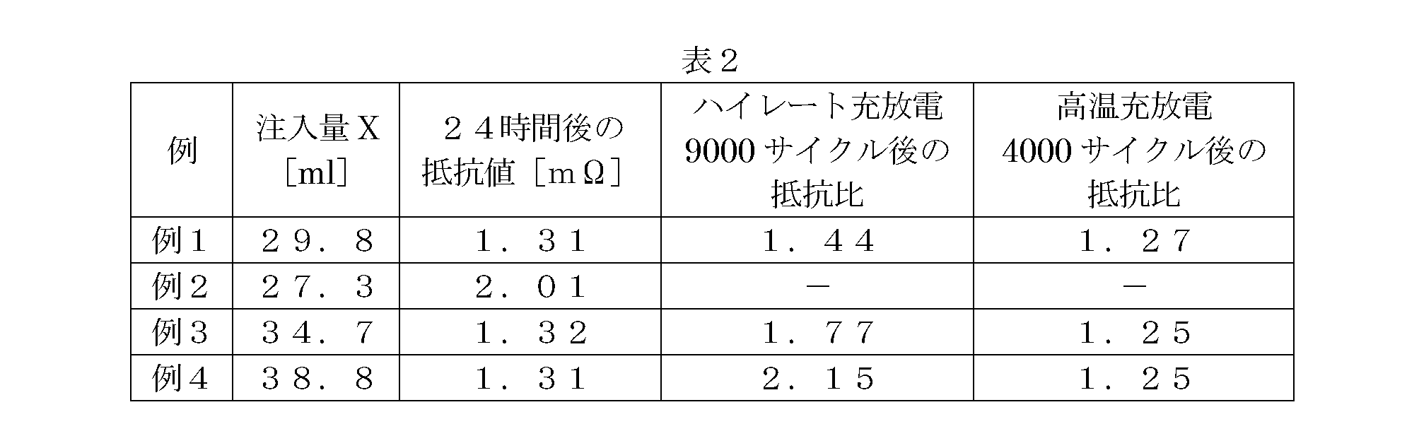
- Example 2 As shown in Table 2, since substantially the same resistance value was obtained in the secondary batteries according to Example 1, Example 3 and Example 4, each wound electrode body was impregnated with a sufficient amount of electrolyte. It was confirmed that The secondary battery according to Example 2 was considered to have increased resistance without being impregnated with the electrolyte solution in the whole wound electrode body because the amount of the electrolyte solution was insufficient as compared with the secondary battery according to Example 1. .
- ⁇ Resistance measurement test 1> The resistance ratio after 9000 cycles of high-rate charge / discharge was measured for one secondary battery among the two secondary batteries of Example 1 after the resistance measurement after the electrolyte injection.
- the initial resistance was measured. That is, after adjusting to a SOC 60% state of charge, a constant current discharge is performed for 10 seconds at 10 C under a temperature condition of 25 ° C., and a linear approximation line of the plot value of current (I) ⁇ voltage (V) at this time The initial resistance was determined from the slope.
- charging and discharging were repeated for 9000 cycles, and the resistance after 1000, 2000, 3000, 5000, 7000, 9000 cycles was measured.
- the charge / discharge conditions for one cycle were: discharge at 10 ° C. for 10 seconds under a temperature condition of ⁇ 15 ° C., charge for 120 seconds at 2C after 5 seconds of rest.
- the resistance after each cycle was determined by the same method as when the initial resistance was measured.
- the ratio of the resistance after 9000 cycles to the initial resistance was defined as the resistance ratio after 9000 cycles.
- the resistance ratio after 9000 cycles was measured for the secondary batteries according to Examples 2 to 4. The measurement results are shown in FIG. In the secondary battery according to Example 2, the resistance ratio after 9000 cycles could not be measured because the non-aqueous electrolyte was insufficient.
- the secondary batteries according to Example 3 and Example 4 had an excessive amount of non-aqueous electrolyte injected into the cell case as compared with the secondary battery of Example 1, so that the resistance It was confirmed that the increase of It was confirmed that the increase in resistance increases as the amount of electrolyte increases.
- ⁇ Resistance measurement test 2> Moreover, the resistance ratio after 4000 cycles of high-temperature charge / discharge was measured for the remaining one secondary battery among the two secondary batteries of Example 1 after the resistance measurement after the electrolyte injection.
- the initial resistance was measured in the same manner as in the resistance measurement test 1.
- charge / discharge was repeated 4000 cycles, and the resistance after 4000 cycles was measured.
- the charge and discharge conditions for one cycle were 60 ° C. under a temperature condition of 2C and the CC / CV system was charged up to an upper limit voltage of 4.1V, and then CC was discharged at 2C to a lower limit voltage of 3.0V.
- the resistance after 4000 cycles was determined by the same method as when the initial resistance was measured. At this time, the ratio of the resistance after 4000 cycles to the initial resistance (resistance after 4000 cycles / initial resistance) was defined as the resistance ratio after 4000 cycles. Similarly, the resistance ratio after 4000 cycles was measured for the secondary batteries according to Examples 2 to 4. The measurement results are shown in Table 2. In the secondary battery according to Example 2, the resistance ratio after 4000 cycles could not be measured because the non-aqueous electrolyte was insufficient.
- the secondary battery according to Example 1 had substantially the same resistance ratio as the secondary batteries according to Example 3 and Example 4 into which the nonaqueous electrolyte was excessively injected.
- repeated charge and discharge at a high temperature tends to cause a shortage of non-aqueous electrolyte in the wound electrode body (so-called “withering phenomenon”), but the secondary battery according to Example 1 is excellent without being short of electrolyte.
- the cycle characteristics were exhibited. From the above, it was confirmed that the injection amount of the non-aqueous electrolyte determined based on the above formula (1) is an appropriate amount.
- Example 2> ⁇ Performance evaluation test of positive electrode mixture layer>
- the wound electrode body was formed using the positive electrode sheet A (mixing material density was 2.1 g / cm 3 , Ap was 6.7 ml, and Bp was 1.04). Although it produced, it was measured how the battery performance of a lithium ion secondary battery changed with swelling ratio Bp of a positive electrode sheet.
- a positive electrode sheet B was produced in the same manner as the positive electrode sheet A, except that a positive electrode mixture layer having a composite material density of 1.8 g / cm 3 was provided. At this time, Ap was 9.1 ml and Bp was 1.017.
- a lithium ion secondary battery according to Example 5 was produced in the same manner as in Example 1 except that the positive electrode sheet B was used instead of the positive electrode sheet A. The injection amount X at this time was 32.2 ml.
- a positive electrode sheet C was produced in the same manner as the positive electrode sheet A except that a positive electrode mixture layer having a composite material density of 1.9 g / cm 3 was provided. At this time, Ap was 8.1 ml and Bp was 1.025.
- a lithium ion secondary battery according to Example 6 was produced in the same manner as in Example 1 except that the positive electrode sheet C was used instead of the positive electrode sheet A.
- the injection amount X at this time was 31.2 ml.
- a lithium ion secondary battery according to Example 7 was constructed in the same manner as the lithium ion secondary battery according to Example 1. At this time, Ap was 6.7 ml, and Bp was 1.04.
- a positive electrode sheet D was produced in the same manner as the positive electrode sheet A except that a positive electrode mixture layer having a composite material density of 2.3 g / cm 3 was provided. At this time, Ap was 5.1 ml and Bp was 1.06.
- a lithium ion secondary battery according to Example 8 was produced in the same manner as in Example 1 except that the positive electrode sheet D was used instead of the positive electrode sheet A.
- the injection amount X at this time was 28.3 ml.
- a positive electrode sheet E was produced in the same manner as the positive electrode sheet A except that a positive electrode mixture layer having a composite material density of 2.35 g / cm 3 was provided. At this time, Ap was 4.8 ml and Bp was 1.074.
- a lithium ion secondary battery according to Example 9 was produced in the same manner as in Example 1 except that the positive electrode sheet E was used instead of the positive electrode sheet A. The injection amount X at this time was 28 ml.
- a positive electrode sheet F was produced in the same manner as the positive electrode sheet A, except that a positive electrode mixture layer having a composite material density of 2.4 g / cm 3 was provided. At this time, Ap was 4.5 ml and Bp was 1.09.
- a lithium ion secondary battery according to Example 10 was produced in the same manner as in Example 1 except that the positive electrode sheet F was used instead of the positive electrode sheet A. The injection amount X at this time was 27.8 ml.
- a positive electrode sheet G was produced in the same manner as the positive electrode sheet A, except that a positive electrode mixture layer having a mixture density of 2.45 g / cm 3 was provided. At this time, Ap was 4.2 ml and Bp was 1.113.
- a lithium ion secondary battery according to Example 11 was produced in the same manner as in Example 1 except that the positive electrode sheet G was used instead of the positive electrode sheet A.
- the injection amount X at this time was 27.6 ml.
- a positive electrode sheet H was produced in the same manner as the positive electrode sheet A, except that a positive electrode mixture layer having a mixture density of 2.5 g / cm 3 was provided. At this time, Ap was 3.9 ml and Bp was 1.13.
- a lithium ion secondary battery according to Example 12 was produced in the same manner as in Example 1 except that the positive electrode sheet H was used instead of the positive electrode sheet A. The injection amount X at this time was 27.4 ml.
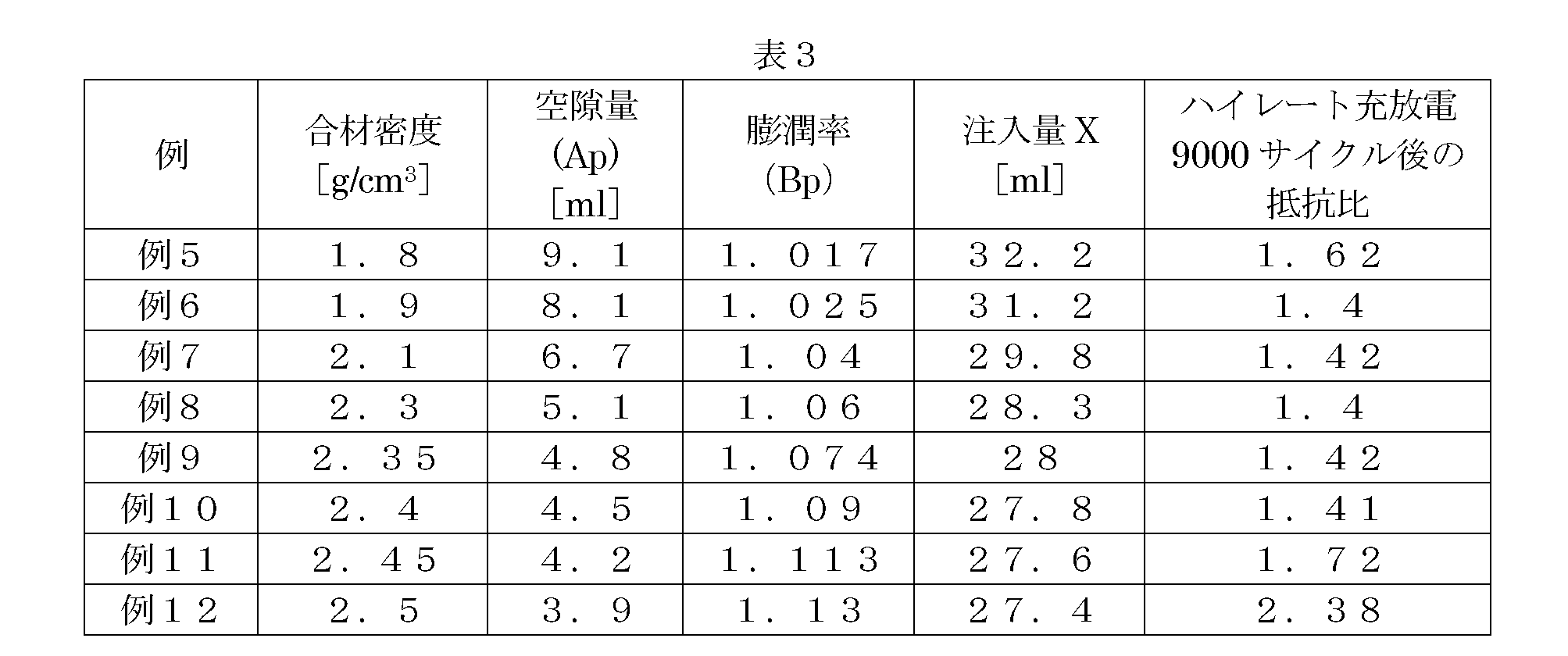
- the resistance ratio was significantly increased when the swelling ratio Bp was greater than 1.11. Further, it was confirmed that the secondary battery having the swelling ratio Bp in the range of 1.02 to 1.09 has a small resistance ratio and a small increase in resistance. From this result, it is appropriate that the positive electrode sheet has an expansion coefficient Bp in the range of 1.01 to 1.11, preferably 1.02 to 1.09 (more preferably 1.025 to 1.09). It was confirmed that.
- Example 3 ⁇ Performance evaluation test of negative electrode composite material layer>
- a wound electrode body was prepared using the negative electrode sheet A (mixing material density was 1 g / cm 3 , An was 7 ml, and Bn was 1.03). However, it was measured how the battery performance of the lithium ion secondary battery changes depending on the swelling ratio Bn of the negative electrode sheet.
- a negative electrode sheet B was produced in the same manner as the negative electrode sheet A except that a negative electrode mixture layer having a composite material density of 0.88 g / cm 3 was provided. At this time, An was 9.8 ml and Bn was 1.015.
- a lithium ion secondary battery according to Example 13 was produced in the same manner as in Example 1 except that the negative electrode sheet B was used instead of the negative electrode sheet A. The injection amount X at this time was 32.5 ml.
- a negative electrode sheet C was produced in the same manner as the negative electrode sheet A, except that a negative electrode mixture layer having a composite material density of 0.93 g / cm 3 was provided. At this time, An was 8.6 ml and Bn was 1.022.
- a lithium ion secondary battery according to Example 14 was produced in the same manner as in Example 1 except that the negative electrode sheet C was used instead of the negative electrode sheet A.
- the injection amount X at this time was 31.4 ml.
- a lithium ion secondary battery according to Example 15 was constructed in the same manner as the lithium ion secondary battery according to Example 1. At this time, An was 7 and Bn was 1.03.
- a negative electrode sheet D was produced in the same manner as the negative electrode sheet A except that a negative electrode mixture layer having a composite material density of 1.2 g / cm 3 was provided. At this time, An was 3.6 and Bn was 1.055.
- a lithium ion secondary battery according to Example 16 was produced in the same manner as in Example 1 except that the negative electrode sheet D was used instead of the negative electrode sheet A.
- the injection amount X at this time was 26.4 ml.
- a negative electrode sheet E was produced in the same manner as the negative electrode sheet A except that a negative electrode mixture layer having a composite material density of 1.3 g / cm 3 was provided. At this time, Bn was 2.4 and An was 1.07.
- a lithium ion secondary battery according to Example 17 was produced in the same manner as in Example 1 except that the negative electrode sheet E was used instead of the negative electrode sheet A.
- the injection amount X at this time was 25.2 ml.
- Example 18 A negative electrode sheet F was produced in the same manner as the negative electrode sheet A except that a negative electrode mixture layer having a composite density of 1.4 g / cm 3 was provided. At this time, An was 1.3 and Bn was 1.086.
- a lithium ion secondary battery according to Example 18 was produced in the same manner as Example 1 except that the negative electrode sheet F was used instead of the negative electrode sheet A. The injection amount X at this time was 24 ml.
- a negative electrode sheet G was produced in the same manner as the negative electrode sheet A except that a negative electrode mixture layer having a composite density of 1.45 g / cm 3 was provided. At this time, An was 0.8 and Bn was 1.11.
- a lithium ion secondary battery according to Example 19 was produced in the same manner as in Example 1 except that the negative electrode sheet G was used instead of the negative electrode sheet A.
- the injection amount X at this time was 23.5 ml.
- a negative electrode sheet H was produced in the same manner as the negative electrode sheet A, except that a negative electrode mixture layer having a composite material density of 1.5 g / cm 3 was provided. At this time, An was 0.3 ml and Bn was 1.127.
- a lithium ion secondary battery according to Example 20 was produced in the same manner as in Example 1 except that the negative electrode sheet H was used instead of the negative electrode sheet A. The injection amount X at this time was 22.9 ml.
- the resistance ratio after 9000 cycles of high-rate charge / discharge was measured in the same manner as the resistance measurement test 1 of Experimental Example 1 for one of the two secondary batteries of Example 13 constructed as described above. Similarly, the resistance ratios of the secondary batteries according to Examples 14 to 20 were measured. The measurement results are shown in FIG.
- the charge / discharge conditions for one cycle are: CCCV charge (constant current / constant voltage charge) up to an upper limit voltage of 4.1V at 2C and a CC discharge (constant current discharge) up to a lower limit voltage of 3.0V at 2C.
- CCCV charge constant current / constant voltage charge
- CC discharge constant current discharge
- the capacity retention ratio [%] was calculated from the discharge capacity at the 4000th cycle relative to the discharge capacity at the 1st cycle. The results are shown in FIG.
- the resistance ratio of the secondary battery having a swelling rate Bn larger than 1.03 was kept small.
- the secondary battery having a swelling rate Bn smaller than 1.09 has an excellent capacity retention rate. From the above results, it is appropriate that the swelling ratio Bn of the negative electrode sheet is larger than 1.03, preferably 1.03 to 1.09 (for example, 1.03 to 1.086), more preferably. 1.05 to 1.09 (for example, 1.055 to 1.086) was confirmed.
- a secondary battery for example, a lithium ion secondary battery
- an assembled battery manufactured by the method according to the present invention are injected with an appropriate amount of an electrolyte, and therefore the electrolyte is depleted during high-rate charge / discharge.
- It can be a secondary battery with excellent performance in which resistance is prevented from increasing or lithium salt in the electrolyte is prevented from flowing out. Due to such characteristics, the secondary battery according to the present invention can be suitably used as a power source for a motor (electric motor) mounted on a vehicle such as an automobile. Therefore, according to the present invention, as schematically shown in FIG. 11, the secondary battery 10 (which may be in the form of an assembled battery 200 formed by connecting a plurality of the batteries 10 in series) is used as a power source. It is possible to provide a vehicle 100 provided (typically, an automobile including an electric motor such as an automobile, particularly a hybrid automobile or an electric automobile).
- Lithium ion secondary battery (secondary battery) 15 Cell Case 20 Opening 25 Lid 30 Case Body 35A, 35B Inner Wall 40 Safety Valve 50 Winding Electrode Body 55A, 55B Flat Surface 60 Positive Terminal 62 Positive Electrode Current Collector 64 Positive Electrode Sheet (Positive Electrode) 66 Positive electrode mixture layer 80 Negative electrode terminal 82 Negative electrode current collector 84 Negative electrode sheet (negative electrode) 90 Negative electrode composite material layer 95 Separator sheet 100 Vehicle (automobile) 110 Cooling plate 120 End plate 130 Restraint band 140 Connection member 150 Spacer member 155 Screw 200 Battery assembly (secondary battery)
Landscapes
- Chemical & Material Sciences (AREA)
- Chemical Kinetics & Catalysis (AREA)
- Electrochemistry (AREA)
- General Chemical & Material Sciences (AREA)
- Engineering & Computer Science (AREA)
- Manufacturing & Machinery (AREA)
- Physics & Mathematics (AREA)
- Condensed Matter Physics & Semiconductors (AREA)
- General Physics & Mathematics (AREA)
- Inorganic Chemistry (AREA)
- Secondary Cells (AREA)
- Battery Electrode And Active Subsutance (AREA)
Abstract
Description
この種のリチウムイオン二次電池の一つの典型的な構成では、正極シートと負極シートとをセパレータシートを介在させた状態で捲回してプレスすることにより得られた扁平形状の捲回電極体が非水電解液と共に角型の電池ケース(典型的には扁平形状の箱型ケース)に収容されている。
そこで、本発明は、上述した従来の課題を解決すべく創出されたものであり、その目的は、セルケースの緊縛の程度から該セルケースに注入する非水電解液の適切な量を決定することにより電池特性、特にサイクル特性に優れる二次電池の製造方法を提供することである。
X=(Ap×Bp)+(An×Bn)+C+(D×E) (1)
に基づいて決定されることを特徴とする。
ここで上記式(1)中、Apは、上記正極合材層の空隙量[ml]である。
Bpは、非水電解液を上記正極合材層に含浸させる前の該正極合材層の厚みをTp0とし、含浸させた後の該正極合材層の厚みをTp1としたときに、Tp1/Tp0によって定められる膨潤率である。
Anは、上記負極合材層の空隙量[ml]である。
Bnは、非水電解液を上記負極合材層に含浸させる前の該負極合材層の厚みをTn0とし、含浸させた後の該負極合材層の厚みをTn1としたときに、Tn1/Tn0によって定められる膨潤率である。
Cは、上記セパレータシートの空隙量[ml]である。
Dは、上記正極合材層と上記負極合材層とが対向する面の総面積[cm2]である。
Eは、上記セルケースを緊縛する前の該セルケースの幅広面の内壁と上記捲回電極体の扁平面との距離をL0とし、上記セルケースを緊縛した後の該セルケースの幅広面の内壁と上記捲回電極体の扁平面との距離をL1としたときに、(L0-L1)/L0×100によって定められる緊縛率[%]に応じて決定される上記対向する面の単位面積当たりの基準電解液量[ml/cm2]である。
上記方法で決定された非水電解液量は、セルケースの緊縛率に応じて決定される基準電解液量を考慮して決定されているため、形成された捲回電極体が収容されたセルケースに適切な量の非水電解液を注入することができる。従って、かかる方法によると、セルケースに注入する非水電解液が不足したり過剰になったりすることが無いため、よりサイクル特性に優れた二次電池を製造することが可能となる。
かかる態様によると、セルケースを上記範囲内の緊縛率で緊縛しているため、二次電池を繰り返し充放電しても該セルケース内に収容された捲回電極体の変形が低減されて出力の低下を防止することができる。
かかる態様によると、ハイレート充放電時の抵抗増加を低減することができるため、サイクル特性に優れる二次電池を製造することができる。
かかる態様によると、ハイレート充放電時の抵抗増加を低減し、また、高い電池容量を維持することができるため、サイクル特性に優れる二次電池を製造することができる。
かかる態様、即ち、複数のセルケースを配列してなる(典型的には複数のセルを電気的に接続してなる)組電池の製造方法において、各セルケースに収容されている捲回電極体の大きさ(配列方向の厚み)にバラツキがあるため各セルケースの緊縛率が異なる場合であっても、各セルケースに適切な量の非水電解液を注入することができる。従って、セルごとの性能のバラツキを低減した組電池を製造することができる。
ここで開示される二次電池の製造方法では、セルケースに注入する非水電解液の注入量X[ml]が以下の式(1):
X=(Ap×Bp)+(An×Bn)+C+(D×E) (1)
に基づいて決定される。
Bpは、正極合材層に非水電解液を含浸させたときの膨潤率である。図4に示すように、膨潤率Bpは、非水電解液(例えばリチウム塩を含まないジメチルカーボネート)を正極合材層66に含浸させる前の該正極合材層66の厚みをTp0とし、非水電解液を正極合材層66に含浸させた後の該正極合材層66の厚みをTp1としたときに、Tp1/Tp0によって定めることができる。このとき、正極合材層66の全体に亘り非水電解液が行き渡るように所定の時間(例えば少なくとも6時間、更には少なくとも24時間)十分な量の非水電解液に浸漬させる。なお、本明細書において「合材層の厚み」は、平均厚さをいい、マイクロメータや断面SEM(走査型電子顕微鏡)写真から測定することができる。
正極シートとしては、膨張率Bpの値が1.01以上、又は1.02以上であって、1.11以下、又は1.09以下の正極シートを用いることが好ましい。例えば、膨張率Bpの値が1.01~1.11の正極シートを用いることが好ましい。より好ましくは、1.02~1.09の正極シートを用いることである。膨潤率Bpは、正極合材層を形成する際のプレス圧によって調整することができる。
Bnは、負極合材層に非水電解液を含浸させたときの膨潤率である。膨潤率Bnは、上述した正極合材層の膨潤率Bpと同様にして、非水電解液を負極合材層に含浸させる前の該負極合材層の厚みをTn0とし、非水電解液を負極合材層に含浸させた後の該負極合材層の厚みをTn1としたときに、Tn1/Tn0によって定めることができる。
負極シートとしては、膨張率Bnの値が1.03以上、又は1.05以上であって、1.13以下、1.09以下の負極シートを用いることが好ましい。例えば、1.03~1.09の負極シート、好ましくは1.05~1.09の負極シートを用いることである。膨潤率Bpは、負極合材層を形成する際のプレス圧によって調整することができる。
なお、上述した正極シートの空孔率Hp、負極シートの空孔率Hn及びセパレートシートの空孔率Hsは、水銀ポロシメーターを用いた水銀圧入法によっても算出することができる。
緊縛率Fは、セルケースを緊縛する前の該セルケースの幅広面の内壁と捲回電極体の扁平面との距離をL0とし、セルケースを緊縛した後の該セルケースの幅広面の内壁と捲回電極体の扁平面との距離をL1としたときに、F[%]=(L0-L1)/L0×100によって定められる。ここでセルケースを「緊縛する」とは、該セルケースの内部空間を挟んで対向する二つの幅広面と交差する方向(典型的には直交する方向、即ち後述する図5においては上下方向)に該セルケースの外方から該幅広面に荷重を加えて上記セルケースの対向する二つの幅広面を互いに接近させることをいう。
例えば、図5に示すように、L0は、セルケース15(ケース本体30)を緊縛する前の該セルケース15の幅広面の内壁35Aと捲回電極体50の扁平面55Aとの距離Laと、内壁35Bと扁平面55Bとの距離Lbとの合計長さ(即ちL0=La+Lb)である。また、L1は、セルケース15(ケース本体30)を緊縛した後の該セルケース15の幅広面の内壁35Aと捲回電極体50の扁平面55Aとの距離Lcと、内壁35Bと扁平面55Bとの距離Ldとの合計長さ(即ちL1=Lc+Ld)である。
緊縛率Fは、90%~100%の範囲内であることが好ましい。緊縛率Fが90%よりも低すぎる場合には、二次電池の充放電を繰り返し行うことによって捲回電極体が変形してしまい出力が低下する虞がある。一方、緊縛率Fが100%を上回るとセルケースが捲回電極体を押し潰してしまい不具合が発生する虞がある。
まず、上記Ap及びBp及びDが測定された正極シートと、上記An及びBnが測定された負極シートと、上記Cが測定されたセパレータシートとを用意して、該正極シートと該負極シートとを該セパレータシートを介在させた状態で捲回して押しつぶすことによって扁平形状の捲回電極体を形成する。該形成された捲回電極体を捲回電極体の扁平面に対応する二つの幅広面を有する角型形状のセルケースに収容する。このとき、該セルケースの幅広面の内壁と捲回電極体の扁平面との距離L0を測定する。距離L0を測定した後、セルケースの対向する二つの幅広面が互いに接近するように該セルケースの外方から該幅広面に荷重を加えて該セルケースを緊縛する。このとき、該セルケースの幅広面の内壁と捲回電極体の扁平面との距離L1を測定して(L0-L1)/L0×100によって緊縛率F[%]を定める。

また、一般式がLiMPO4或いはLiMVO4或いはLi2MSiO4(式中のMはCo、Ni、Mn、Feのうちの少なくとも一種以上の元素)等で表記されるようなポリアニオン系化合物(例えばLiFePO4、LiMnPO4、LiFeVO4、LiMnVO4、Li2FeSiO4、Li2MnSiO4、Li2CoSiO4)を上記正極活物質として用いてもよい。
上記導電材としては、従来この種のリチウムイオン二次電池で用いられているものであればよく、特定の導電材に限定されない。例えば、カーボン粉末やカーボンファイバー等のカーボン材料を用いることができる。カーボン粉末としては、種々のカーボンブラック(例えば、アセチレンブラック、ファーネスブラック、ケッチェンブラック等)、グラファイト粉末等のカーボン粉末を用いることができる。これらのうち一種又は二種以上を併用してもよい。
上記結着材としては、一般的なリチウムイオン二次電池の負極に使用される結着材と同様のものを適宜採用することができる。例えば、負極合材層を形成するために水系のペースト状組成物を用いる場合には、水に溶解または分散するポリマー材料を好ましく採用し得る。水に分散する(水分散性の)ポリマー材料としては、スチレンブタジエンゴム(SBR)、フッ素ゴム等のゴム類;ポリエチレンオキサイド(PEO)、ポリテトラフルオロエチレン(PTFE)等のフッ素系樹脂;酢酸ビニル共重合体等が例示される。
なお、以下の図面において、同じ作用を奏する部材・部位には同じ符号を付し、重複する説明は省略することがある。また、各図における寸法関係(長さ、幅、厚さ等)は、必ずしも実際の寸法関係を反映するものではない。
図1に示すように、本実施形態に係るリチウムイオン二次電池10は、金属製(樹脂製又はラミネートフィルム製も好適である。)のセルケース15を備える。このセルケース(外容器)15は、上端が開放されており捲回電極体50の扁平面に対応する二つの幅広面を有する直方体形状のケース本体30と、その開口部20を塞ぐ蓋体25とを備える。溶接等により蓋体25は、ケース本体30の開口部20を封止している。セルケース15の上面(すなわち蓋体25)には、捲回電極体50の正極シート(正極)64と電気的に接続する正極端子60および該電極体の負極シート84と電気的に接続する負極端子80が設けられている。また、蓋体25には、従来のリチウムイオン二次電池のケースと同様に、電池異常の際にセルケース15内部で発生したガスをセルケース15の外部に排出するための安全弁40が設けられている。セルケース15の内部には、正極シート64と負極シート84とを計二枚の長尺なセパレータシート95を介在して積層させた状態で捲回して、次いで得られた捲回体を側面方向から押しつぶして拉げさせることによって作製される扁平形状の捲回電極体50収容されている。セルケース15は、図示しない拘束具によって対向する二つの幅広面が互いに接近するように緊縛されている。そして、上記式(1)に基づいて決定された注入量X[ml]の非水電解液がセルケース15内に注入されて捲回電極体50に含浸している。
図3に示すように、この組電池(二次電池)200は、複数個(典型的には10個以上、好ましくは10~30個程度、例えば20個)のリチウムイオン二次電池(セル)10を、それぞれの正極端子60および負極端子80が交互に配置されるように一つずつ反転させつつ、セルケース15の幅広面が対向する方向(積層方向)に配列されている。当該配列されたセル10間には、所定形状の冷却板110が挟み込まれている。この冷却板110は、使用時に各単電池10内で発生する熱を効率よく放散させるための放熱部材として機能するものであって、好ましくはセル10間に冷却用流体(典型的には空気)を導入可能な形状(例えば、長方形状の冷却板の一辺から垂直に延びて対向する辺に至る複数の平行な溝が表面に設けられた形状)を有する。熱伝導性の良い金属製もしくは軽量で硬質なポリプロピレンその他の合成樹脂製の冷却板が好適である。
まず、以下の各例におけるリチウムイオン二次電池(二次電池)に使用した捲回電極体の構成部材について説明する。
<正極シートA>
正極活物質としてのLiNi1/3Co1/3Mn1/3O2と、導電材としてのアセチレンブラックと、結着材(バインダ)としてのPVDFとの質量比が88:10:2となるように秤量し、これら材料をNMPに分散させてペースト状の正極合材層形成用組成物を調製した。該組成物をアルミニウム箔(正極集電体)上に片面当たり塗布量6mg/cm2塗布して乾燥させ、ロールプレスによる処理を行うことにより合材密度が2.1g/cm3の正極合材層をアルミニウム箔上に形成してなる長尺な正極シートAを作製した。正極シートAのApは6.7mlであり、Bpは1.04であった。また、正極合材層と負極シートAの負極合材層とが対向する面の総面積、即ち、正極合材層の総面積Dは7115.4cm2であった。
<負極シートA>
負極活物質としての天然黒鉛と、結着材としてのSBRと、増粘材としてのCMCとの質量比が98:1:1となるように秤量し、これら材料を水に分散させてペースト状の負極合材層形成用組成物を調製した。該組成物を銅箔(負極集電体)上に片面当たり塗布量4mg/cm2塗布して乾燥させ、ロールプレスによる処理を行うことにより合材密度が1g/cm3の負極合材層を銅箔上に形成してなる長尺な負極シートAを作製した。負極シートAのAnは7mlであり、Bnは1.03であった。
<セパレータシートA>
厚さ20μmのポリプロピレン/ポリエチレン/ポリプロピレン三層多孔質シートAを使用した。Cは7.87mlであった。
<例1>
上記作製した正極シートAと負極シートAとを2枚のセパレータシートAを介在させた状態で捲回して押しつぶすことによって例1に係る扁平形状の捲回電極体を作製(形成)した。該電極体を角型形状のセルケースに収容して該セルケースの幅広面に荷重を加えて緊縛した。このときの緊縛率Fは96%であった。上記相関式(E=-0.0754F+8.4157)と緊縛率F(96%)とから基準電解液量Eを求めて、上記式(1)に基づいて決定された注入量X(X=29.8ml)の非水電解液をセルケースに注入することにより例1に係るリチウムイオン二次電池を2個構築した。非水電解液としては、エチレンカーボネート(EC)とエチルメチルカーボネート(EMC)とジメチルカーボネート(DMC)との体積比3:3:4の混合溶媒に1mol/LのLiPF6を溶解させたものを用いた。
<例2>
非水電解液の注入量を例1に係る注入量よりも2.5ml少ない27.3mlとした他は例1と同様にして、例2に係るリチウムイオン二次電池を2個構築した。
<例3>
非水電解液の注入量を例1に係る注入量よりも4.9ml多い34.7mlとした他は例1と同様にして、例3に係るリチウムイオン二次電池を2個構築した。
<例4>
非水電解液の注入量を例1に係る注入量よりも9ml多い38.8mlとした他は例1と同様にして、例4に係るリチウムイオン二次電池を2個構築した。
上記非水電解液注入後の例1~例4に係る各二次電池について、注入後24時間経過後の抵抗値を測定した。即ち、市販のインピーダンス測定装置を用いて、各二次電池の交流1kHzインピーダンスを測定した。測定結果の平均値を表2に示す。
上記電解液注入後抵抗測定後の例1の2個の二次電池のうち1個の二次電池についてハイレート充放電9000サイクル後の抵抗比を測定した。まず初期抵抗を測定した。即ち、SOC60%の充電状態に調整した後、25℃の温度条件下、10Cで10秒間の定電流放電を行い、このときの電流(I)‐電圧(V)のプロット値の一次近似直線の傾きから初期抵抗を求めた。
次いで、上記初期抵抗測定後の二次電池について、充放電を9000サイクル繰り返し、1000,2000,3000,5000,7000,9000サイクル後の抵抗を測定した。1サイクルの充放電条件は、-15℃の温度条件下、20Cで10秒間放電を行い、休止5秒間の後、2Cで120秒間充電を行った。上記各サイクル後の抵抗は、上記初期抵抗を測定したときと同様の手法により求めた。このとき、初期抵抗に対する9000サイクル後の抵抗の比(9000サイクル後の抵抗/初期抵抗)を、9000サイクル後の抵抗比とした。同様にして例2~例4に係る二次電池について9000サイクル後の抵抗比を測定した。測定結果を図7及び表2に示す。なお、例2に係る二次電池では非水電解液が不足したため9000サイクル後の抵抗比を測定することができなかった。
また、上記電解液注入後抵抗測定後の例1の2個の二次電池のうち残りの1個の二次電池について高温充放電4000サイクル後の抵抗比を測定した。まず上記抵抗測定試験1と同様にして初期抵抗を測定した。
次いで、上記初期抵抗測定後の二次電池について、充放電を4000サイクル繰り返し、4000サイクル後の抵抗を測定した。1サイクルの充放電条件は、60℃の温度条件下、2Cで上限電圧4.1VまでCC/CV方式で充電を行い、その後2Cで下限電圧3.0VまでCC放電を行った。上記4000サイクル後の抵抗は、上記初期抵抗を測定したときと同様の手法により求めた。このとき、初期抵抗に対する4000サイクル後の抵抗の比(4000サイクル後の抵抗/初期抵抗)を、4000サイクル後の抵抗比とした。同様にして例2~例4に係る二次電池について4000サイクル後の抵抗比を測定した。測定結果を表2に示す。なお、例2に係る二次電池では非水電解液が不足したため4000サイクル後の抵抗比を測定することができなかった。
以上より、上記式(1)に基づいて決定した非水電解液の注入量は適切な量であることが確認された。
<正極合材層の性能評価試験>
上記例1~例4では、正極シートA(合材密度は2.1g/cm3であり、Apは6.7mlであり、Bpは1.04である。)を用いて捲回電極体を作製していたが、正極シートの膨潤率Bpによってリチウムイオン二次電池の電池性能がどのように変化するのかを測定した。
合材密度が1.8g/cm3の正極合材層を備える他は正極シートAと同様にして、正極シートBを作製した。このときApは9.1mlであり、Bpは1.017であった。正極シートAに代えて正極シートBを用いた他は例1と同様にして、例5に係るリチウムイオン二次電池を作製した。このときの注入量Xは32.2mlであった。
<例6>
合材密度が1.9g/cm3の正極合材層を備える他は正極シートAと同様にして、正極シートCを作製した。このときApは8.1mlであり、Bpは1.025であった。正極シートAに代えて正極シートCを用いた他は例1と同様にして、例6に係るリチウムイオン二次電池を作製した。このときの注入量Xは31.2mlであった。
<例7>
例1に係るリチウムイオン二次電池と同様にして、例7に係るリチウムイオン二次電池を構築した。このときApは6.7mlであり、Bpは1.04であった。
<例8>
合材密度が2.3g/cm3の正極合材層を備える他は正極シートAと同様にして、正極シートDを作製した。このときApは5.1mlであり、Bpは1.06であった。正極シートAに代えて正極シートDを用いた他は例1と同様にして、例8に係るリチウムイオン二次電池を作製した。このときの注入量Xは28.3mlであった。
<例9>
合材密度が2.35g/cm3の正極合材層を備える他は正極シートAと同様にして、正極シートEを作製した。このときApは4.8mlであり、Bpは1.074であった。正極シートAに代えて正極シートEを用いた他は例1と同様にして、例9に係るリチウムイオン二次電池を作製した。このときの注入量Xは28mlであった。
<例10>
合材密度が2.4g/cm3の正極合材層を備える他は正極シートAと同様にして、正極シートFを作製した。このときApは4.5mlであり、Bpは1.09であった。正極シートAに代えて正極シートFを用いた他は例1と同様にして、例10に係るリチウムイオン二次電池を作製した。このときの注入量Xは27.8mlであった。
<例11>
合材密度が2.45g/cm3の正極合材層を備える他は正極シートAと同様にして、正極シートGを作製した。このときApは4.2mlであり、Bpは1.113であった。正極シートAに代えて正極シートGを用いた他は例1と同様にして、例11に係るリチウムイオン二次電池を作製した。このときの注入量Xは27.6mlであった。
<例12>
合材密度が2.5g/cm3の正極合材層を備える他は正極シートAと同様にして、正極シートHを作製した。このときApは3.9mlであり、Bpは1.13であった。正極シートAに代えて正極シートHを用いた他は例1と同様にして、例12に係るリチウムイオン二次電池を作製した。このときの注入量Xは27.4mlであった。
<負極合材層の性能評価試験>
また、上記例1~例4では、負極シートA(合材密度は1g/cm3であり、Anは7mlであり、Bnは1.03である。)を用いて捲回電極体を作製していたが、負極シートの膨潤率Bnによってリチウムイオン二次電池の電池性能がどのように変化するのかを測定した。
合材密度が0.88g/cm3の負極合材層を備える他は負極シートAと同様にして、負極シートBを作製した。このときAnは9.8mlであり、Bnは1.015であった。負極シートAに代えて負極シートBを用いた他は例1と同様にして、例13に係るリチウムイオン二次電池を作製した。このときの注入量Xは32.5mlであった。
<例14>
合材密度が0.93g/cm3の負極合材層を備える他は負極シートAと同様にして、負極シートCを作製した。このときAnは8.6mlであり、Bnは1.022であった。負極シートAに代えて負極シートCを用いた他は例1と同様にして、例14に係るリチウムイオン二次電池を作製した。このときの注入量Xは31.4mlであった。
<例15>
例1に係るリチウムイオン二次電池と同様にして、例15に係るリチウムイオン二次電池を構築した。このときAnは7であり、Bnは1.03であった。
<例16>
合材密度が1.2g/cm3の負極合材層を備える他は負極シートAと同様にして、負極シートDを作製した。このときAnは3.6であり、Bnは1.055であった。負極シートAに代えて負極シートDを用いた他は例1と同様にして、例16に係るリチウムイオン二次電池を作製した。このときの注入量Xは26.4mlであった。
<例17>
合材密度が1.3g/cm3の負極合材層を備える他は負極シートAと同様にして、負極シートEを作製した。このときBnはAnは2.4であり、1.07であった。負極シートAに代えて負極シートEを用いた他は例1と同様にして、例17に係るリチウムイオン二次電池を作製した。このときの注入量Xは25.2mlであった。
<例18>
合材密度が1.4g/cm3の負極合材層を備える他は負極シートAと同様にして、負極シートFを作製した。このときAnは1.3であり、Bnは1.086であった。負極シートAに代えて負極シートFを用いた他は例1と同様にして、例18に係るリチウムイオン二次電池を作製した。このときの注入量Xは24mlであった。
<例19>
合材密度が1.45g/cm3の負極合材層を備える他は負極シートAと同様にして、負極シートGを作製した。このときAnは0.8であり、Bnは1.11であった。負極シートAに代えて負極シートGを用いた他は例1と同様にして、例19に係るリチウムイオン二次電池を作製した。このときの注入量Xは23.5mlであった。
<例20>
合材密度が1.5g/cm3の負極合材層を備える他は負極シートAと同様にして、負極シートHを作製した。このときAnは0.3mlであり、Bnは1.127であった。負極シートAに代えて負極シートHを用いた他は例1と同様にして、例20に係るリチウムイオン二次電池を作製した。このときの注入量Xは22.9mlであった。

15 セルケース
20 開口部
25 蓋体
30 ケース本体
35A,35B 内壁
40 安全弁
50 捲回電極体
55A,55B 扁平面
60 正極端子
62 正極集電体
64 正極シート(正極)
66 正極合材層
80 負極端子
82 負極集電体
84 負極シート(負極)
90 負極合材層
95 セパレータシート
100 車両(自動車)
110 冷却板
120 エンドプレート
130 拘束バンド
140 接続部材
150 スペーサ部材
155 ビス
200 組電池(二次電池)
Claims (5)
- 二次電池を製造する方法であって、
正極集電体上に正極合材層が形成された長尺な正極シートを用意すること、
負極集電体上に負極合材層が形成された長尺な負極シートを用意すること、
前記正極シートと前記負極シートとを長尺なセパレータシートを介在させた状態で捲回して押しつぶすことによって扁平形状の捲回電極体を形成すること、
前記捲回電極体の扁平面に対応する二つの幅広面を有する角型形状のセルケースに前記捲回電極体を収容すること、
前記セルケースの対向する二つの幅広面が互いに接近するように該セルケースの外方から該幅広面に荷重を加えて該セルケースを緊縛すること、
前記緊縛されたセルケースに非水電解液を注入すること、
を包含し、
ここで、前記非水電解液の注入量X[ml]は以下の式(1):
X=(Ap×Bp)+(An×Bn)+C+(D×E) (1)
(式(1)中、Apは、前記正極合材層の空隙量[ml]であり、Bpは、非水電解液を前記正極合材層に含浸させる前の該正極合材層の厚みをTp0とし、含浸させた後の該正極合材層の厚みをTp1としたときに、Tp1/Tp0によって定められる膨潤率であり、
Anは、前記負極合材層の空隙量[ml]であり、Bnは、非水電解液を前記負極合材層に含浸させる前の該負極合材層の厚みをTn0とし、含浸させた後の該負極合材層の厚みをTn1としたときに、Tn1/Tn0によって定められる膨潤率であり、
Cは、前記セパレータシートの空隙量[ml]であり、
Dは、前記正極合材層と前記負極合材層とが対向する面の総面積[cm2]であり、
Eは、前記セルケースを緊縛する前の該セルケースの幅広面の内壁と前記捲回電極体の扁平面との距離をL0とし、前記セルケースを緊縛した後の該セルケースの幅広面の内壁と前記捲回電極体の扁平面との距離をL1としたときに、(L0-L1)/L0×100によって定められる緊縛率[%]に応じて決定される前記対向する面の単位面積当たりの基準電解液量[ml/cm2]である。)
に基づいて決定されることを特徴とする、二次電池の製造方法。 - 前記緊縛率が90%~100%となるように前記セルケースを緊縛したときに、前記Eの値が0.9×10⁻³ml/cm2~1.7×10-3ml/cm2の範囲内で決定されることを特徴とする、請求項1に記載の製造方法。
- 前記Bpの値が1.02~1.09の範囲内となる合材密度の正極合材層を備える正極シートを用いることを特徴とする、請求項1又は2に記載の製造方法。
- 前記Bnの値が1.03~1.09の範囲内となる合材密度の負極合材層を備える負極シートを用いることを特徴とする、請求項1から3のいずれか一項に記載の製造方法。
- 前記捲回電極体が収容された複数の前記セルケースを該セルケースの幅広面が対向するように配列し、前記複数のセルケースの配列方向に荷重を加えて該複数のセルケースを緊縛し、前記各セルケースの緊縛率に基づいて該各セルケースに注入する非水電解液量が決定されることを特徴とする、請求項1から4のいずれか一項に記載の製造方法。
Priority Applications (4)
| Application Number | Priority Date | Filing Date | Title |
|---|---|---|---|
| JP2013521352A JP5757329B2 (ja) | 2011-06-20 | 2011-06-20 | 二次電池の製造方法 |
| US14/127,715 US9269988B2 (en) | 2011-06-20 | 2011-06-20 | Method for manufacturing secondary battery |
| PCT/JP2011/064075 WO2012176272A1 (ja) | 2011-06-20 | 2011-06-20 | 二次電池の製造方法 |
| CN201180071741.3A CN103636055B (zh) | 2011-06-20 | 2011-06-20 | 二次电池的制造方法 |
Applications Claiming Priority (1)
| Application Number | Priority Date | Filing Date | Title |
|---|---|---|---|
| PCT/JP2011/064075 WO2012176272A1 (ja) | 2011-06-20 | 2011-06-20 | 二次電池の製造方法 |
Publications (1)
| Publication Number | Publication Date |
|---|---|
| WO2012176272A1 true WO2012176272A1 (ja) | 2012-12-27 |
Family
ID=47422154
Family Applications (1)
| Application Number | Title | Priority Date | Filing Date |
|---|---|---|---|
| PCT/JP2011/064075 Ceased WO2012176272A1 (ja) | 2011-06-20 | 2011-06-20 | 二次電池の製造方法 |
Country Status (4)
| Country | Link |
|---|---|
| US (1) | US9269988B2 (ja) |
| JP (1) | JP5757329B2 (ja) |
| CN (1) | CN103636055B (ja) |
| WO (1) | WO2012176272A1 (ja) |
Cited By (3)
| Publication number | Priority date | Publication date | Assignee | Title |
|---|---|---|---|---|
| JP2015153727A (ja) * | 2014-02-19 | 2015-08-24 | トヨタ自動車株式会社 | リチウムイオン二次電池 |
| JP2019160587A (ja) * | 2018-03-14 | 2019-09-19 | 三洋電機株式会社 | 非水電解質二次電池及びそれを用いた組電池 |
| CN114883641A (zh) * | 2022-04-22 | 2022-08-09 | 上海空间电源研究所 | 一种latp基固态电解质界面层及latp基固态锂电池的制备方法 |
Families Citing this family (4)
| Publication number | Priority date | Publication date | Assignee | Title |
|---|---|---|---|---|
| WO2015111665A1 (ja) * | 2014-01-23 | 2015-07-30 | 株式会社豊田自動織機 | 蓄電装置の製造方法、製造装置、注液装置、及び注液方法 |
| CN108847472A (zh) * | 2018-05-07 | 2018-11-20 | 浙江天能动力能源有限公司 | 一种确定铅酸蓄电池加酸量的方法 |
| CN109326764B (zh) * | 2018-08-24 | 2021-08-03 | 台州钱江新能源研究院有限公司 | 一种锂离子电池电解液保有量精准化控制方法 |
| US20230163309A1 (en) * | 2021-11-22 | 2023-05-25 | Enevate Corporation | Silicon based lithium ion battery and improved cycle life of same |
Citations (4)
| Publication number | Priority date | Publication date | Assignee | Title |
|---|---|---|---|---|
| JP2000123872A (ja) * | 1998-10-16 | 2000-04-28 | Toyota Central Res & Dev Lab Inc | リチウム二次電池 |
| JP2002270225A (ja) * | 2001-03-09 | 2002-09-20 | Matsushita Electric Ind Co Ltd | リチウム二次電池 |
| JP2006351249A (ja) * | 2005-06-13 | 2006-12-28 | Fdk Corp | 非水電解液二次電池 |
| JP2011060564A (ja) * | 2009-09-10 | 2011-03-24 | Murata Mfg Co Ltd | 蓄電デバイスの製造方法 |
Family Cites Families (2)
| Publication number | Priority date | Publication date | Assignee | Title |
|---|---|---|---|---|
| JPH0831458A (ja) | 1994-05-09 | 1996-02-02 | Fuji Photo Film Co Ltd | 非水二次電池 |
| JP5165875B2 (ja) | 2006-10-16 | 2013-03-21 | 株式会社東芝 | 非水電解質電池 |
-
2011
- 2011-06-20 US US14/127,715 patent/US9269988B2/en active Active
- 2011-06-20 JP JP2013521352A patent/JP5757329B2/ja active Active
- 2011-06-20 WO PCT/JP2011/064075 patent/WO2012176272A1/ja not_active Ceased
- 2011-06-20 CN CN201180071741.3A patent/CN103636055B/zh active Active
Patent Citations (4)
| Publication number | Priority date | Publication date | Assignee | Title |
|---|---|---|---|---|
| JP2000123872A (ja) * | 1998-10-16 | 2000-04-28 | Toyota Central Res & Dev Lab Inc | リチウム二次電池 |
| JP2002270225A (ja) * | 2001-03-09 | 2002-09-20 | Matsushita Electric Ind Co Ltd | リチウム二次電池 |
| JP2006351249A (ja) * | 2005-06-13 | 2006-12-28 | Fdk Corp | 非水電解液二次電池 |
| JP2011060564A (ja) * | 2009-09-10 | 2011-03-24 | Murata Mfg Co Ltd | 蓄電デバイスの製造方法 |
Cited By (4)
| Publication number | Priority date | Publication date | Assignee | Title |
|---|---|---|---|---|
| JP2015153727A (ja) * | 2014-02-19 | 2015-08-24 | トヨタ自動車株式会社 | リチウムイオン二次電池 |
| JP2019160587A (ja) * | 2018-03-14 | 2019-09-19 | 三洋電機株式会社 | 非水電解質二次電池及びそれを用いた組電池 |
| JP7087488B2 (ja) | 2018-03-14 | 2022-06-21 | 三洋電機株式会社 | 非水電解質二次電池及びそれを用いた組電池 |
| CN114883641A (zh) * | 2022-04-22 | 2022-08-09 | 上海空间电源研究所 | 一种latp基固态电解质界面层及latp基固态锂电池的制备方法 |
Also Published As
| Publication number | Publication date |
|---|---|
| US9269988B2 (en) | 2016-02-23 |
| CN103636055A (zh) | 2014-03-12 |
| JP5757329B2 (ja) | 2015-07-29 |
| CN103636055B (zh) | 2016-01-13 |
| US20140310950A1 (en) | 2014-10-23 |
| JPWO2012176272A1 (ja) | 2015-02-23 |
Similar Documents
| Publication | Publication Date | Title |
|---|---|---|
| US8658305B2 (en) | Lithium-ion battery and use thereof | |
| US9263729B2 (en) | Lithium secondary battery | |
| JP5257700B2 (ja) | リチウム二次電池 | |
| JP5787194B2 (ja) | 電源システム | |
| US20120288759A1 (en) | Lithium secondary battery | |
| JP5696904B2 (ja) | リチウムイオン二次電池およびその製造方法 | |
| JP5709010B2 (ja) | 非水電解液二次電池 | |
| JP5812336B2 (ja) | 二次電池 | |
| JP5818078B2 (ja) | 非水電解質二次電池の製造方法 | |
| JP5757329B2 (ja) | 二次電池の製造方法 | |
| JP6176500B2 (ja) | 二次電池及びその製造方法ならびに該電池に用いられる負極シートの製造方法 | |
| JP5765574B2 (ja) | 二次電池及びその製造方法ならびに該電池に用いられる負極シートの製造方法 | |
| EP3127176B1 (en) | Nonaqueous electrolyte secondary battery | |
| JP5737595B2 (ja) | 二次電池 | |
| JP2013069579A (ja) | リチウムイオン二次電池とその製造方法 | |
| JP2012238461A (ja) | 二次電池及びその製造方法 | |
| JP5418828B2 (ja) | リチウム二次電池とその製造方法 | |
| JP5999433B2 (ja) | 非水電解液二次電池及びその製造方法 | |
| KR101980422B1 (ko) | 비수 전해액 이차 전지 | |
| JP2012156061A (ja) | 二次電池とその製造方法 | |
| JP5692605B2 (ja) | 非水電解液二次電池 | |
| JP6008188B2 (ja) | 非水電解液二次電池 | |
| CN105493319A (zh) | 负极活性物质、使用该负极活性物质的负极、以及锂离子二次电池 | |
| JP6735036B2 (ja) | リチウムイオン二次電池 | |
| JP2014130729A (ja) | 非水電解液二次電池の製造方法 |
Legal Events
| Date | Code | Title | Description |
|---|---|---|---|
| 121 | Ep: the epo has been informed by wipo that ep was designated in this application |
Ref document number: 11868263 Country of ref document: EP Kind code of ref document: A1 |
|
| ENP | Entry into the national phase |
Ref document number: 2013521352 Country of ref document: JP Kind code of ref document: A |
|
| NENP | Non-entry into the national phase |
Ref country code: DE |
|
| WWE | Wipo information: entry into national phase |
Ref document number: 14127715 Country of ref document: US |
|
| 122 | Ep: pct application non-entry in european phase |
Ref document number: 11868263 Country of ref document: EP Kind code of ref document: A1 |