WO2012173107A1 - 情報処理装置と情報処理方法ならびにプログラム - Google Patents
情報処理装置と情報処理方法ならびにプログラム Download PDFInfo
- Publication number
- WO2012173107A1 WO2012173107A1 PCT/JP2012/064984 JP2012064984W WO2012173107A1 WO 2012173107 A1 WO2012173107 A1 WO 2012173107A1 JP 2012064984 W JP2012064984 W JP 2012064984W WO 2012173107 A1 WO2012173107 A1 WO 2012173107A1
- Authority
- WO
- WIPO (PCT)
- Prior art keywords
- proximity detection
- information processing
- proximity
- detected
- processing apparatus
- Prior art date
Links
Images


Classifications
-
- G—PHYSICS
- G06—COMPUTING; CALCULATING OR COUNTING
- G06F—ELECTRIC DIGITAL DATA PROCESSING
- G06F3/00—Input arrangements for transferring data to be processed into a form capable of being handled by the computer; Output arrangements for transferring data from processing unit to output unit, e.g. interface arrangements
- G06F3/01—Input arrangements or combined input and output arrangements for interaction between user and computer
- G06F3/048—Interaction techniques based on graphical user interfaces [GUI]
- G06F3/0487—Interaction techniques based on graphical user interfaces [GUI] using specific features provided by the input device, e.g. functions controlled by the rotation of a mouse with dual sensing arrangements, or of the nature of the input device, e.g. tap gestures based on pressure sensed by a digitiser
- G06F3/0488—Interaction techniques based on graphical user interfaces [GUI] using specific features provided by the input device, e.g. functions controlled by the rotation of a mouse with dual sensing arrangements, or of the nature of the input device, e.g. tap gestures based on pressure sensed by a digitiser using a touch-screen or digitiser, e.g. input of commands through traced gestures
- G06F3/04886—Interaction techniques based on graphical user interfaces [GUI] using specific features provided by the input device, e.g. functions controlled by the rotation of a mouse with dual sensing arrangements, or of the nature of the input device, e.g. tap gestures based on pressure sensed by a digitiser using a touch-screen or digitiser, e.g. input of commands through traced gestures by partitioning the display area of the touch-screen or the surface of the digitising tablet into independently controllable areas, e.g. virtual keyboards or menus
-
- G—PHYSICS
- G06—COMPUTING; CALCULATING OR COUNTING
- G06F—ELECTRIC DIGITAL DATA PROCESSING
- G06F3/00—Input arrangements for transferring data to be processed into a form capable of being handled by the computer; Output arrangements for transferring data from processing unit to output unit, e.g. interface arrangements
- G06F3/01—Input arrangements or combined input and output arrangements for interaction between user and computer
- G06F3/03—Arrangements for converting the position or the displacement of a member into a coded form
- G06F3/041—Digitisers, e.g. for touch screens or touch pads, characterised by the transducing means
- G06F3/0416—Control or interface arrangements specially adapted for digitisers
- G06F3/0418—Control or interface arrangements specially adapted for digitisers for error correction or compensation, e.g. based on parallax, calibration or alignment
- G06F3/04186—Touch location disambiguation
-
- G—PHYSICS
- G06—COMPUTING; CALCULATING OR COUNTING
- G06F—ELECTRIC DIGITAL DATA PROCESSING
- G06F2203/00—Indexing scheme relating to G06F3/00 - G06F3/048
- G06F2203/041—Indexing scheme relating to G06F3/041 - G06F3/045
- G06F2203/04101—2.5D-digitiser, i.e. digitiser detecting the X/Y position of the input means, finger or stylus, also when it does not touch, but is proximate to the digitiser's interaction surface and also measures the distance of the input means within a short range in the Z direction, possibly with a separate measurement setup
-
- G—PHYSICS
- G06—COMPUTING; CALCULATING OR COUNTING
- G06F—ELECTRIC DIGITAL DATA PROCESSING
- G06F2203/00—Indexing scheme relating to G06F3/00 - G06F3/048
- G06F2203/041—Indexing scheme relating to G06F3/041 - G06F3/045
- G06F2203/04108—Touchless 2D- digitiser, i.e. digitiser detecting the X/Y position of the input means, finger or stylus, also when it does not touch, but is proximate to the digitiser's interaction surface without distance measurement in the Z direction
-
- G—PHYSICS
- G06—COMPUTING; CALCULATING OR COUNTING
- G06F—ELECTRIC DIGITAL DATA PROCESSING
- G06F3/00—Input arrangements for transferring data to be processed into a form capable of being handled by the computer; Output arrangements for transferring data from processing unit to output unit, e.g. interface arrangements
- G06F3/01—Input arrangements or combined input and output arrangements for interaction between user and computer
- G06F3/03—Arrangements for converting the position or the displacement of a member into a coded form
- G06F3/041—Digitisers, e.g. for touch screens or touch pads, characterised by the transducing means
- G06F3/044—Digitisers, e.g. for touch screens or touch pads, characterised by the transducing means by capacitive means
- G06F3/0446—Digitisers, e.g. for touch screens or touch pads, characterised by the transducing means by capacitive means using a grid-like structure of electrodes in at least two directions, e.g. using row and column electrodes
Definitions
- This technology relates to an information processing apparatus, an information processing method, and a program. Specifically, an information processing apparatus, an information processing method, and a program capable of correctly performing an input operation are provided.
- a touch panel such as a capacitance method or a resistance film method to perform an input operation.
- a capacitive touch panel as in Patent Document 1 and Patent Document 2, by detecting a change in capacitance caused by bringing an operation body such as a finger or a contact pen into contact with the touch panel operation surface, The contact position is detected.
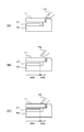
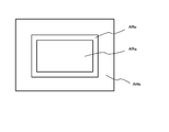
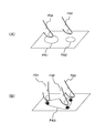
- FIG. 1 illustrates a schematic cross-sectional view of an information processing apparatus using a touch panel.
- a display unit 21 is provided inside the housing 50 of the information processing apparatus, and a touch panel that is the sensor unit 11 is provided on the display surface side of the display unit 21.
- a change in capacitance occurs, and it is erroneously detected that an input operation has been performed in the active area ARb close to the finger FG. It may be done.
- the finger FG is close to the inactive area ARa as shown in FIG. 1B or when the finger is in contact with the inactive area ARa as shown in FIG. In some cases, it is erroneously detected that an input operation has been performed.
- the position of the other finger may be erroneously detected as the operation position when another finger approaches the active area ARb.
- an object of this technology is to provide an information processing apparatus, an information processing method, and a program that can correctly perform an input operation.
- a first aspect of the technology includes a sensor unit that generates a sensor signal according to the proximity and contact of the operating body, a proximity detection unit that performs proximity detection of the operating body based on the sensor signal, and the proximity detection
- the information processing apparatus includes a determination unit that sets a priority order for the detected operation objects and adopts a proximity detection result based on the set priority order.
- proximity detection of the operating body is performed by the proximity detection unit based on a sensor signal generated according to the proximity and contact of the operating body by a sensor unit, for example, a capacitive touch panel.
- a priority order is set for the detected operation objects. For example, the priority of the operating body positioned in a predetermined area provided in the area where the contact of the operating body can be detected is increased. Further, when a plurality of operating bodies are located in the predetermined area, the priority order of the operating body having a high signal strength of the sensor signal is increased. The proximity detection result is adopted based on the priority order set in this way.
- the determination unit determines that the operation tool is invalid when the detection size of the operation tool detected by the proximity detection is larger than the threshold value. Further, when a plurality of operating objects are detected by proximity detection, individual processing or integration processing of proximity detection results is performed. For example, as an individual process, based on the proximity detection results of a plurality of detected operating bodies, the area corresponding to each operating body is displayed on the display unit, and the display size of the area display is set according to the signal strength of the sensor signal. As processing and integration processing, processing for displaying a region surrounded by the positions indicated by the plurality of proximity detection results on the display unit is performed based on the proximity detection results of the plurality of operating objects detected.
- the proximity detection result is validated and can be operated. If it is outside the area, the detection invalid flag is set and the proximity detection result is invalidated. In addition, the detection invalid flag is set because the detection position is outside the operable area, and if the detection position moves to the position of the detection invalid flag release area within the operable area, the detection invalidity The flag is released and the proximity detection result is validated. Further, when the operating body is detected by the proximity detection unit, the operable region is displayed on the display unit in an identifiable manner.
- the detection sensitivity of the proximity detection in the proximity detection unit is controlled by the proximity detection control unit, and for example, the detection sensitivity on the end side of the region where the contact of the operating body can be detected is lower than the other parts.
- a second aspect of the present technology includes a step of generating a sensor signal corresponding to the proximity and contact of the operating body, a step of performing proximity detection of the operating body based on the sensor signal, and a plurality of operations by the proximity detection.
- a body is detected, a priority order is set for the detected operating body, and a proximity detection result is adopted based on the set priority order.
- a procedure for performing proximity detection of the operating body based on a sensor signal generated according to the proximity and contact of the operating body in the sensor unit, and a plurality of operating bodies are detected by the proximity detection
- the computer program causes the computer to execute a procedure of setting a priority order for the detected operating body and adopting the proximity detection result based on the set priority order.
- the program of the present technology is, for example, a storage medium or communication medium provided in a computer-readable format to a general-purpose computer system capable of executing various program codes, such as an optical disk, a magnetic disk, a semiconductor memory, and the like. Or a program that can be provided by a communication medium such as a network. By providing such a program in a computer-readable format, processing corresponding to the program is realized on the computer system.
- the detected operation A priority is set for the body, and the proximity detection result is adopted based on the set priority. For this reason, even if a plurality of operating bodies are detected, it is possible to prevent erroneous detection by adopting a proximity detection result having a high priority, and an input operation can be performed correctly.
- the information processing apparatus using the present technology includes a display unit 21 inside a housing 50 of the information processing apparatus, and a sensor unit 11 on the display surface side of the display unit 21. It has been configured.
- the sensor unit 11 is a capacitive touch panel.
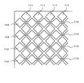
- FIG. 2 shows the configuration of the touch panel.
- the touch panel uses a translucent substrate, and the active region that receives an operation input intersects the first translucent electrode pattern 111 extending in the first direction with the first translucent electrode pattern 111 in the first direction.
- a plurality of rows of second light transmissive electrode patterns 112 extending in the second direction are formed.
- an operation body such as a finger or a touch pen is located in the vicinity, in proximity, or in contact with the touch panel.
- a capacitance is generated between the first translucent electrode pattern 111 and the second translucent electrode pattern 112 and the operation body. Therefore, it can be detected from the change in capacitance that the operating body is located in the vicinity, and at which location the operating body is close or in contact.
- the first translucent electrode pattern 111 and the second translucent electrode pattern 112 are formed of the same layer on the same surface of the translucent substrate. Moreover, since the 1st translucent electrode pattern 111 and the 2nd translucent electrode pattern 112 are formed by the same layer on the same surface of a translucent board
- one electrode pattern of the first translucent electrode pattern 111 and the second translucent electrode pattern 112 is connected at the intersecting portion, while the other electrode pattern is The configuration is interrupted.
- the first translucent electrode pattern 111 is connected to any of the plurality of intersecting portions, while the second translucent electrode pattern 112 is interrupted.
- a translucent interlayer insulating film is formed on the upper side of the first translucent electrode pattern 111 at the intersection.
- a translucent relay electrode 113 (shaded portion) that electrically connects the second translucent electrode patterns 112 that are interrupted at the intersecting portions is formed on the upper layer of the interlayer insulating film. For this reason, the 2nd translucent electrode pattern is electrically connected by the 2nd direction.
- each of the first translucent electrode pattern 111 and the second translucent electrode pattern 112 includes a rhombus-shaped large-area pad portion in a region sandwiched between the intersecting portions.
- the connection portion located at the intersecting portion in the first translucent electrode pattern 111 has a narrow shape that is narrower than the pad portion.
- the relay electrode 113 is also formed in a strip shape having a narrow width narrower than that of the pad portion.
- the sensor unit 11 configured as described above generates a sensor signal indicating a change in capacitance caused by the proximity or contact of the operating body and outputs the sensor signal to the proximity detection unit 12.
- the display unit 21 is configured using a flat display element such as a liquid crystal display element.
- the display unit 21 displays a menu screen for setting the information processing apparatus and switching operations.
- a backlight is provided between the display unit 21 and the housing 50, and the display unit 21 is illuminated from the back side of the display unit 21, that is, the surface side facing the housing 50.
- the structure which makes it easy to see the display of the display part 21 may be sufficient.
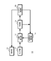
- FIG. 3 shows a functional block diagram of the information processing apparatus.
- the information processing apparatus 10 includes a sensor unit 11, a proximity detection unit 12, a determination unit 13, a proximity detection control unit 14, a display unit 21, and a system control unit 30.
- the sensor unit 11 generates a sensor signal indicating a change in capacitance caused by the proximity or contact of the operating body as described above, and outputs the sensor signal to the proximity detection unit 12.
- the proximity detection unit 12 detects the proximity of the operating body based on the sensor signal from the sensor unit 11.
- the proximity detection unit 12 performs proximity detection and outputs a detection result to the determination unit 13.
- a detection result indicating the proximity detection state and a detection result indicating the proximity detection state are generated.
- the proximity detection state refers to a state in which the position of the operating body cannot be detected but the operating body is in the vicinity of the sensor unit 11.
- the proximity detection state refers to a state in which the position of the operating body that is in proximity to or in contact with the sensor unit 11 is detected.
- the determination unit 13 determines the validity of the proximity detection result according to whether or not the detection position detected by the proximity detection is within an operable area provided in an area where the contact of the operating body can be detected. To do.
- the determination unit 13 outputs an effective proximity detection result or a proximity detection result and an effectiveness determination result to the system control unit 30. Further, when a plurality of operation objects are detected by proximity detection, the determination unit 13 sets a priority order for the detected operation objects, and adopts a proximity detection result based on the set priority order. Output to the control unit 30.
- the proximity detection control unit 14 controls the detection sensitivity of the proximity detection in the proximity detection unit 12 based on the control signal supplied from the system control unit 30 and the determination result of the determination unit 13.
- the system control unit 30 generates a display signal and outputs it to the display unit 21. Further, the system control unit 30 performs individual processing or integration processing of the proximity detection result based on the proximity detection result supplied from the determination unit 13. Further, the system control unit 30 determines the operation performed by the user from the proximity detection result supplied from the determination unit 13 and the display performed on the display unit 21, and based on the determination result, the information processing apparatus 10. The control is performed so that the above operation becomes an operation according to the user operation.
- the information processing apparatus 10 determines whether the proximity detection result is valid depending on whether or not the detection position of the operating tool detected by the proximity detection is within an operable area provided in the area where the touch of the operating tool can be detected. Therefore, it is possible to prevent erroneous detection of an input operation.
- the information processing apparatus 10 detects a plurality of operation objects in proximity detection, the information processing apparatus 10 sets a priority order for the detected operation objects, and adopts the proximity detection result based on the set priority order. This prevents erroneous detection of input operations. Further, the information processing apparatus 10 prevents detection errors by controlling detection sensitivity in proximity detection of the operating tool.
- the first operation an operation for determining the validity of the proximity detection result will be described.
- an operation when a plurality of operation objects are detected will be described.
- an operation for controlling the detection sensitivity of proximity detection will be described.
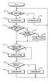
- FIG. 4 is a flowchart showing a first operation of the information processing apparatus 10.
- the information processing apparatus 10 determines whether it is in the proximity / proximity detection state.
- the information processing apparatus 10 proceeds to step ST ⁇ b> 2 when the operating body approaches the sensor unit 11 and enters the proximity detection state, or when the operating body enters the proximity detection state due to proximity or contact with the sensor unit 11. .
- the information processing apparatus 10 proceeds to step ST11 in other cases.
- step ST2 the information processing apparatus 10 displays the operable area. Since the operating tool is approaching the touch panel, the information processing apparatus 10 displays the operable area on the display unit 21 and proceeds to step ST3. As shown in FIG. 5, the operable area ARp is an area provided in the active area ARb, which is an area where contact of the operating body can be detected, and is associated with the display on the display unit 21.
- step ST3 the information processing apparatus 10 determines whether or not the proximity detection state has first shifted to the proximity detection state.
- the information processing apparatus 10 proceeds to step ST4 when the operating tool first enters or comes into contact with the operation unit from the vicinity of the sensor unit 11, and proceeds to step ST6 in other cases.
- step ST4 the information processing apparatus 10 proceeds to step ST6 when the detected position is within the operable region, and proceeds to step ST5 in other cases.
- step ST5 the information processing apparatus 10 sets a detection invalid flag and proceeds to step ST6.
- step ST6 the information processing apparatus 10 determines whether the detection invalid flag is set and the detection position is within the detection invalid flag release region.
- the detection invalid flag release area ARq is an area provided in the operable area ARp as shown in FIG. If the detection invalid flag is set and the detection position is within the detection invalid flag release region, the information processing apparatus 10 proceeds to step ST7. In other cases, the information processing apparatus 10 proceeds to step ST8.
- step ST7 the information processing apparatus 10 releases the detection invalid flag.
- the information processing apparatus 10 cancels the set detection invalidation flag and proceeds to step ST8.
- step ST8 the information processing apparatus 10 determines whether the detection invalid flag is set. The information processing apparatus 10 proceeds to step ST9 when the detection invalid flag is set, and proceeds to step ST10 when the detection invalid flag is released.
- step ST9 the information processing apparatus 10 invalidates the proximity detection result generated by the proximity detection unit 12 and returns to step ST1.
- step ST10 the information processing apparatus 10 validates the proximity detection result generated by the proximity detection unit 12 and returns to step ST1.
- the information processing apparatus 10 hides the operable area.
- the operating body is not close to or in contact with the sensor unit 11 and is not in the vicinity, it cannot be determined that a user operation is being performed. Therefore, the information processing apparatus 10 hides the operable area. Further, the information processing apparatus 10 can reduce power consumption by, for example, turning off the backlight when not displaying the operable area.
- step ST1 to step ST11 it is not necessary to perform all the processes from step ST1 to step ST11, and some processes may be selectively performed. For example, only the processing from step ST3 to step ST10 may be performed.
- FIG. 6 illustrates the display of the operable area.
- the information processing apparatus 10 hides the operable region as “button 1” in FIG. Also, the color is low, such as “Button 2”.
- the button display is set to a small size.
- the operable region is not displayed, for example, the backlight may be turned off and the display on the display unit 21 may be displayed in black. Alternatively, a standby screen display may be used.
- the operable region is displayed as “button 1” in FIG. 6B, for example. Further, the color is high, such as “Button 2”. When the display size is changed, the display is a large size such as “button 3”. In addition, when the backlight is turned off when the operable area is not displayed, the backlight is turned on and the display unit 21 performs display. In the display of the operable region, it is possible to identify the display state by adding gradation or animation to the button or icon display.
- FIG. 7 shows the relationship between the movement of the operating tool and the vicinity detection result.
- FIG. 7A when the operating body approaches the sensor unit 11 and enters the proximity detection state, and then enters the proximity detection state for the first time, detection is performed when the detection position is outside the operable region ARp. Invalid flag is set. If the detection invalid flag is set, the proximity detection result is invalidated. Thus, since the proximity detection result is invalidated, no erroneous detection occurs when the operating tool approaches the outside of the operable region.
- the detection invalid flag is set by shifting from the proximity detection state to the proximity detection state for the first time, as shown in FIG. 7B, the operation tool is in the operable area ARp and the detection invalid flag release area. Even if the proximity detection state is entered at a position outside ARq, the proximity detection result is invalidated. Also, as shown in FIG. 7C, when the detection position of the operating tool is in the detection invalid flag release area ARq, the detection invalid flag is released and the proximity detection result is validated.
- the area for setting the detection invalid flag and the area for releasing the detection invalid flag are different areas, and the detection invalid flag release area is within the operable area and is narrower than the operable area. Has been. Therefore, the effectiveness of the proximity detection result can be determined stably.
- the setting of the operable area and detection invalid flag release area can be easily performed by using a register.
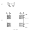
- a register For example, as shown in FIG. 8A, an 8-bit register is provided, for example, the upper 4 bits of the register, the threshold for setting the range of the area in the X-axis direction, the lower 4 bits of the register, It is set as a threshold for setting the range of the area in the direction.
- FIG. 8B shows a case where the operable area is set with the register set to “0x42”, for example.
- the resolution in the X-axis direction and the resolution in the Y-axis direction in the sensor unit 11 are “1023”, respectively.
- the area “32 to 991” excluding the range of “4 ⁇ 8” from the end side in the X-axis direction is set as the operable area. Since the lower 4 bits are “2”, the area “16 to 1007” excluding the range of “2 ⁇ 8”, for example, in the Y-axis direction is set as the operable area. In this manner, the operable area can be easily set by using the register. Similarly, the detection invalid flag release area can be easily set using a register.
- the proximity of the operating body is detected based on the sensor signal generated in accordance with the proximity and contact of the operating body, and the detection position detected by the proximity detection is The validity of the proximity detection result is determined depending on whether or not the region is within the operable region provided in the region where the contact of the body can be detected. For this reason, it becomes possible to prevent erroneous detection and perform an input operation correctly.
- the detection invalid flag is set because the detection position is outside the operable area, and if the detection position moves to the position of the detection invalid flag release area within the operable area, the detection invalidity The flag is released and the proximity detection result is validated. Therefore, a more reliable proximity detection result can be used as compared with the conventional information processing apparatus that uses the proximity detection result when the operating body is in the proximity detection state.
- the detection invalid flag release area may be set offset from the center of the operable area. For example, when the information processing apparatus is held by hand, the detection invalid flag release region in FIG. If the detection invalid flag release area is set in this way, the detection invalid flag is less likely to be canceled by mistake, and erroneous detection can be prevented more reliably.
- the operable region is displayed on the display unit in an identifiable manner. For this reason, since the user can easily confirm the position of the operable region, an erroneous operation can be prevented by referring to the display.
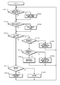
- FIG. 9 is a flowchart showing a second operation of the information processing apparatus 10.
- the information processing apparatus 10 determines whether there is an operating tool whose detection area is less than a threshold value.
- the information processing apparatus 10 proceeds to step ST22 when there is no operation object whose detection area is less than the threshold value, and proceeds to step ST23 when there is an operation object whose detection area is less than the threshold value.
- step ST22 the information processing apparatus 10 invalidates the operation tool whose detection area is equal to or larger than the threshold value.
- the information processing apparatus 10 invalidates the operation body having a detection area larger than the threshold, for example, the operation body such as the back of the hand or the palm having a detection area larger than that of the finger when the operation is performed with the finger, and proceeds to step ST23.
- step ST23 the information processing apparatus 10 determines whether a plurality of proximity detections are performed.
- the information processing apparatus 10 proceeds to step ST25 when there are a plurality of proximity-detected operating bodies, and proceeds to step ST24 when there is one.
- step ST24 the information processing apparatus 10 employs the detected operating tool.
- the information processing apparatus 10 adopts the detected operating body because the number of operating bodies whose detection area is less than the threshold is 1, and proceeds to step ST25.
- step ST25 the information processing apparatus 10 determines whether the multi-proximity detection mode is selected. If the multi-proximity detection mode using a plurality of proximity detection results is selected, the information processing apparatus 10 proceeds to step ST31. If the multi-proximity detection mode is not selected, the process proceeds to step ST26.
- step ST26 the information processing apparatus 10 determines whether there is an operating tool in the predetermined area. If the information processing apparatus 10 is in a predetermined area, for example, in an area in which contact of the operating tool can be detected, and the operating tool is within a certain range from the center of the screen of the display unit 21, the process proceeds to step ST27. Further, the information processing apparatus 10 proceeds to step ST30 when there is no operation tool in the predetermined area.
- step ST27 the information processing apparatus 10 determines whether there is only one operating tool in the predetermined area. If there is one operating tool in the predetermined area, the information processing apparatus 10 proceeds to step ST28. Further, when there are a plurality of operating objects in the predetermined area, the information processing apparatus 10 proceeds to step ST29.
- step ST28 the information processing apparatus 10 employs an operating tool in a predetermined area.
- the information processing apparatus 10 outputs the proximity detection result of the operating tool in the predetermined area from the determination unit 13 to the system control unit 30, and returns to step ST21.
- step ST29 the information processing apparatus 10 employs the operating body having the highest signal intensity within the predetermined area. Since there are a plurality of operating bodies in the predetermined area, the information processing apparatus 10 outputs the proximity detection result of the operating body having the highest signal strength from the determination unit 13 to the system control unit 30 and returns to step ST21.
- the information processing apparatus 10 employs the operating body having the highest signal intensity in the entire region.
- the information processing apparatus 10 outputs the proximity detection result of the operating body having the highest signal intensity in the entire region from the determination unit 13 to the system control unit 30, and returns to step ST21.
- step ST31 the information processing apparatus 10 determines whether it is the individual processing mode. If the individual mode for performing processing using a plurality of proximity detection results separately is selected, the information processing apparatus 10 proceeds to step ST32. If the individual mode is not selected, the process proceeds to step ST33.
- step ST32 the information processing apparatus 10 performs individual processing of the proximity detection result.
- the information processing apparatus 10 performs processing using all the proximity detection results individually, and returns to step ST21. For example, as an individual process, when an identification display corresponding to an operating tool is performed on the display unit 21, an identification display is provided at the detection position of the operating tool detected by proximity detection. Further, the display size of the identification display is set according to the signal intensity when the operating tool is detected.
- step ST33 the information processing apparatus 10 performs integration processing.
- the information processing apparatus 10 performs processing using all the proximity detection results, and returns to step ST21. For example, when the identification display corresponding to the operation tool is performed on the display unit 21 as the integration process, the area surrounded by the detection position of the operation tool detected by the proximity detection is set as the identification display area.
- step ST21 to step ST33 it is not necessary to perform all the processes from step ST21 to step ST33, and some processes may be selectively performed. For example, only the processing from step ST26 to step ST30 may be performed, or only the processing from step ST26 to step ST33 may be performed.
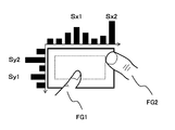
- FIG. 10 illustrates the signal intensity when a plurality of operating bodies are detected.
- the two fingers FG1 and FG2 are operating bodies, and the signal intensity in the X-axis direction of the finger FG1 is “Sx1”, and the signal intensity in the X-axis direction of the finger FG2 is “Sx2”.
- the signal strength in the Y-axis direction of the finger FG1 is “Sy1”, and the signal strength in the Y-axis direction of the finger FG2 is “Sy2”.
- the operating body in the predetermined area is one, and therefore the finger FG1 is adopted as the operating body. become.
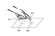
- FIG. 11 shows a case where the hand grip portion FH is close to the sensor unit when the finger FG1 is used as the operating body.
- the hand grip portion FH is larger in size than the finger FG1. Therefore, when the finger FG1 is brought close to the sensor unit, the grip portion FH also approaches the sensor unit.
- the threshold value of the detection area is set smaller than the detection area Sfh of the grip portion FH and larger than the detection area Sfg1 of the finger FG1, even if the grip portion FH is detected as an operating body, it is invalidated. Accordingly, it is possible to detect only the finger FG1 as the operating body, and it is possible to prevent the grip portion FH from being erroneously detected.
- FIG. 12 shows a case where the multi-proximity detection mode is selected.
- FIG. 12A shows a case where the individual processing mode is selected when the multi-proximity detection mode is selected.
- two fingers FG1 and FG2 are used as operating bodies.
- the identification display PA1 corresponding to the finger FG1 is the identification display PA2 corresponding to the finger FG2.
- Increase the display size In this way, the proximity detection result of the operating tool can be easily confirmed on the display of the display unit 21.
- FIG. 12B shows a case where the individual processing mode is not selected when the multi-proximity detection mode is selected.
- three fingers FG1, FG2, and FG3 are used as operating bodies.
- an area surrounded by the positions of the fingers FG1 to FG3 detected by proximity detection is displayed as the identification display PA3.
- the identification display PA3 In this way, when a range is set by a plurality of operating bodies, it is possible to display the range set based on a plurality of proximity detection results, and the region setting state can be easily confirmed.
- priority is set for the detected operation objects. For example, the priority of the operation body located in a predetermined area provided in the area where the contact of the operation body can be detected or the operation body located in the predetermined area and the signal strength of the sensor signal is high is set high.
- the proximity detection result is adopted based on the set priority order. For this reason, even if a plurality of operating bodies are detected, it is possible to prevent erroneous detection by adopting a proximity detection result having a high priority.
- the detected size of the operating tool detected by proximity detection is larger than the threshold value, it is determined that the operating tool is invalid. For this reason, for example, when the finger is brought close to the operable region, even if the grip portion of the hand approaches the sensor portion, it is possible to prevent the grip portion from being erroneously detected as the operating body.
- the operating tool when an operating tool with high signal strength is employed, the operating tool is employed with a hysteresis characteristic so that the operating tool employed is not frequently switched due to fluctuations in the signal strength. If such processing is performed, stable operation is possible.
- the proximity detection control unit 14 controls detection sensitivity of proximity detection performed by the proximity detection unit 12 to prevent erroneous detection.
- the detection sensitivity can be easily controlled by using a register. For example, as shown in FIG. 13A, an 8-bit sensitivity adjustment register is provided to set whether or not sensitivity adjustment is performed in the upper 4 bits of the register, and what sensitivity adjustment is performed in the lower 4 bits. Set whether to perform.
- the most significant bit of the register is, for example, a bit for setting whether or not sensitivity adjustment of the left and right end side sensors X0 and Xm shown in FIG. 13B is performed.
- the second bit indicates whether or not the sensitivity adjustment is performed by the left and right sensors X1 and Xm-1 located inside the sensors X0 and Xm in which the sensitivity adjustment is set by the most significant bit.
- the third bit is a bit for setting whether or not to adjust the sensitivity of the sensors Y0 and Yn on the upper and lower ends.
- the fifth bit included in the lower 4 bits of the register adjusts the sensitivity of sensors X0 and Xm.
- the sixth bit adjusts the sensitivity of the sensors X1, Xm-1.
- the seventh bit adjusts the sensitivity of the sensors Y0 and Yn. In the least significant bit, the sensitivity of the sensors Y1 and Yn-1 is adjusted. Note that sensitivity adjustment can be performed for sensitivity detection for proximity detection by adjusting the gain of the sensor signal and the level of the threshold, for example, when detecting the operating body by comparing the sensor signal with the threshold.
- FIG. 13B shows a case where the sensitivity adjustment register is set to “0xE4”.
- sensitivity adjustment is performed when the bit is “1”, and sensitivity adjustment is not performed when the bit is “0”.
- sensitivity is reduced to “50%”, and when the bit is “0”, the sensitivity is “0%”, that is, proximity detection is not performed. To do.
- the bits from the most significant bit to the third bit are “1”. Therefore, the sensitivity adjustment is performed for the sensors X0, X1, Xm-1, Xm, Y0, and Yn. Do. Since the fourth bit is “0”, the sensitivity adjustment is not performed in the sensors Y 1 and Yn ⁇ 1. Further, since the fifth bit and the seventh bit are “0”, the sensitivities of the sensors X0, Xm, Y0, Yn are set to “0%”. Further, since the sixth bit is “1”, the sensitivity of the sensors X 1 and Xm ⁇ 1 is set to “50%”. Therefore, sensitivity adjustment is performed as shown in FIG.
- the sensitivity adjustment is not limited to the case of using a register. For example, when reading the sensor signal of each sensor from the sensor unit 11, a table indicating the relationship between the reading position and the sensitivity may be prepared, and the sensitivity adjustment may be performed based on the table.
- the sensitivity is set to “0” and the sensor signal is not read, so that the power consumption can be reduced. Furthermore, the directivity of the detection sensitivity can be given according to the proximity detection result already obtained. For example, if the detection sensitivity is increased with respect to the direction of movement of the finger as the operating body, the detection accuracy of the operating body can be increased.
- a ground layer may be provided on the surface of the sensor unit 11.
- a ground layer may be provided on the peripheral edge of the sensor unit 11 to suppress a change in capacitance due to a hand holding the housing.
- a grounded metal plate, a conductive thin film, or the like is used as the ground layer.
- the series of processes described in the specification can be executed by hardware, software, or a combined configuration of both.
- a program in which a processing sequence is recorded is installed and executed in a memory in a computer incorporated in dedicated hardware.
- the program is installed and executed on a general-purpose computer capable of executing various processes.
- the program can be recorded in advance on a hard disk or ROM (Read Only Memory) as a recording medium, for example.
- the program is temporarily or permanently stored on a removable recording medium such as a flexible disk, CD-ROM (Compact Disc Read Only Memory), MO (Magneto optical disc), DVD (Digital Versatile Disc), magnetic disk, or semiconductor memory. It can be stored (recorded).
- a removable recording medium can be provided as so-called package software.
- the program is installed on the computer from the removable recording medium as described above, or is wirelessly transferred from the download site to the computer, or is wired to the computer via a network such as a LAN (Local Area Network) or the Internet.
- the computer receives the program transferred in this way and installs it in a recording medium such as a built-in hard disk.
- the present technology should not be construed as being limited to the embodiments of the technology described above.
- the first to third operations may be performed individually or in combination.
- This embodiment discloses the present technology in the form of exemplification, and it is obvious that those skilled in the art can make modifications and substitutions of the embodiment without departing from the gist of the present technology. In other words, the scope of the claims should be considered in order to determine the gist of the present technology.
- this technique can also take the following structures.
- a sensor unit that generates a sensor signal according to the proximity and contact of the operating body;
- a proximity detector for detecting proximity of the operating body based on the sensor signal;
- a determination unit configured to set a priority order for the detected operation object and adopt a proximity detection result based on the set priority order when a plurality of operation objects are detected by the proximity detection;
- Processing equipment (2)
- the determination unit increases the priority of the operation object having a high signal strength of the sensor signal.
- a display unit for displaying an image is further provided, As the individual processing of the proximity detection result, the control unit performs area display corresponding to each operation body on the display unit based on the proximity detection results of the detected plurality of operation bodies, and the signal intensity of the sensor signal.
- a display unit for displaying an image is further provided, The control unit displays, on the display unit, an area surrounded by the positions indicated by the plurality of proximity detection results based on the proximity detection results of the plurality of operating bodies detected as the integration processing of the proximity detection results (5).
- the determination unit detects the proximity according to whether the detection position detected by the proximity detection is within an operable region provided in a region where the contact of the operating body can be detected.
- the information processing apparatus according to any one of (1) to (7), wherein the validity of the result is determined.
- the determination unit validates the proximity detection result when the detection position is within the operable region, and invalidates the proximity detection result when the detection position is outside the operable region (8).
- the information processing apparatus described. When the detection position is outside the operable area, the determination unit sets a detection invalid flag to invalidate the proximity detection result, and the detection position moves to detect within the operable area.
- a display unit for displaying an image is further provided, The information processing apparatus according to any one of (8) to (10), wherein when the operating body is detected by the proximity detection unit, the display unit displays the operable region in an identifiable manner.
- the proximity detection of the operation body is performed based on the sensor signal generated according to the proximity and contact of the operation body, and a plurality of operation bodies are detected by the proximity detection. Is detected, the priority is set for the detected operating body, and the proximity detection result is adopted based on the set priority. For this reason, even if a plurality of operating bodies are detected, it is possible to prevent erroneous detection by adopting a proximity detection result having a high priority, and an input operation can be performed correctly. Therefore, it is suitable for a device that performs an input operation using a touch panel.
- SYMBOLS 10 Information processing apparatus, 11 ... Sensor part, 12 ... Proximity detection part, 13 ... Discrimination part, 14 ... Proximity detection control part, 21 ... Display part, 30 ... System control unit, 50... Casing, 111... First translucent electrode pattern, 112... Second translucent electrode pattern, 113.
Abstract
センサ部11は、操作体の近接および接触に応じたセンサ信号を生成する。近接検出部12は、センサ信号に基づき、操作体の近接検出を行う。判別部13は、近接検出によって複数の操作体が検出された場合、検出された操作体に対して優先順位を設定して、設定した優先順位に基づいて近接検出結果を採用する。このため、複数の操作体が検出されても、優先順位の高い近接検出結果を採用することで、誤検出を防止することが可能となり、入力操作を正しく行うことができるようになる。
Description
この技術は、情報処理装置と情報処理方法ならびにプログラムに関する。詳しくは、入力操作を正しく行うことができる情報処理装置と情報処理方法ならびにプログラムを提供する。
近年、携帯電話装置や携帯情報端末、携帯音楽プレーヤなどの各種電子機器では、静電容量方式や抵抗膜方式等のタッチパネルを設けて入力操作を行うことが可能とされている。静電容量方式のタッチパネルでは、特許文献1,特許文献2のように、指や接触ペン等の操作体をタッチパネル操作面に接触させることにより生じた静電容量の変化を検出することで、その接触位置が検出されている。
ところで、静電容量方式のタッチパネルでは、入力操作だけでなく他の操作で静電容量が変化した場合でも、入力操作が行われたと誤検出されてしまう場合がある。図1は、タッチパネルを用いた情報処理装置の断面概略図を例示している。情報処理装置の筐体50の内部には表示部21が設けられており、表示部21の表示面側にセンサ部11であるタッチパネルが設けられている。ここで、例えばユーザが図1の(A)に示すように筐体50を持った場合、静電容量の変化が生じて、指FGに近接したアクティブ領域ARbで入力操作が行われたと誤検出されてしまう場合がある。また、図1の(B)に示すように指FGが非アクティブ領域ARaに近接した場合、または図1の(C)に示すように指が非アクティブ領域ARaに接触した場合にも、同様に入力操作が行われたと誤検出されてしまう場合がある。
また、指FGをアクティブ領域ARbに近づけた場合、他の指がアクティブ領域ARbに近づくと、他の指の位置が操作位置として誤検出されてしまう場合もある。
そこで、この技術では入力操作を正しく行うことができる情報処理装置と情報処理方法ならびにプログラムを提供することを目的とする。
この技術の第1の側面は、操作体の近接および接触に応じたセンサ信号を生成するセンサ部と、前記センサ信号に基づき、前記操作体の近接検出を行う近接検出部と、前記近接検出によって複数の操作体が検出された場合、該検出された操作体に対して優先順位を設定して、該設定した優先順位に基づいて近接検出結果を採用する判別部とを備える情報処理装置にある。
この技術においては、センサ部例えば静電容量方式のタッチパネルによって、操作体の近接および接触に応じて生成されたセンサ信号に基づき、操作体の近接検出が近接検出部で行われる。判別部では、近接検出によって複数の操作体が検出された場合、検出された操作体に対して優先順位が設定される。例えば、操作体の接触の検出が可能な領域内に設けた所定領域に位置する操作体の優先順位が高くされる。また、所定領域に複数の操作体が位置する場合、センサ信号の信号強度が高い操作体の優先順位が高くされる。このようにして設定された優先順位に基づいて近接検出結果が採用される。さらに、判別部では、近接検出によって検出された操作体の検出サイズが閾値よりも大きい場合に、この操作体が無効と判別される。また、近接検出によって複数の操作体が検出された場合、近接検出結果の個別処理または統合処理が行われる。例えば個別処理として、検出された複数の操作体の近接検出結果に基づき、個々の操作体に対応する領域表示を表示部で行い、センサ信号の信号強度に応じて領域表示の表示サイズを設定する処理や、統合処理として、検出された複数の操作体の近接検出結果に基づき、複数の近接検出結果が示す位置で囲まれる領域を表示部で表示する処理が行われる。
また、判別部では、近接検出によって検出された検出位置が、例えば操作体の接触の検出が可能な領域内に設けた操作可能領域内である場合に近接検出結果が有効とされて、操作可能領域外である場合に検出無効フラグを設定して近接検出結果が無効とされる。また、検出位置が操作可能領域外の位置であるため検出無効フラグが設定されており、検出位置が移動して操作可能領域内の検出無効フラグ解除領域の位置となった場合には、検出無効フラグが解除されて近接検出結果が有効とされる。また、近接検出部で操作体が検出されている場合、表示部で操作可能領域が識別可能に表示される。
さらに、近接検出部における近接検出の検出感度が近接検出制御部によって制御されて、例えば操作体の接触の検出が可能な領域の端部側の検出感度が他の部分よりも低下される。
この技術の第2の側面は、操作体の近接および接触に応じたセンサ信号を生成する工程と、前記センサ信号に基づき、前記操作体の近接検出を行う工程と、前記近接検出によって複数の操作体が検出された場合、該検出された操作体に対して優先順位を設定して、該設定した優先順位に基づいて近接検出結果を採用する工程とを含む情報処理方法にある。
この技術の第3の側面は、センサ部で操作体の近接および接触に応じて生成されたセンサ信号に基づき、前記操作体の近接検出を行う手順と、前記近接検出によって複数の操作体が検出された場合、該検出された操作体に対して優先順位を設定して、該設定した優先順位に基づいて近接検出結果を採用する手順とをコンピュータで実行させるプログラムにある。
なお、本技術のプログラムは、例えば、様々なプログラム・コードを実行可能な汎用コンピュータ・システムに対して、コンピュータ可読な形式で提供する記憶媒体、通信媒体、例えば、光ディスクや磁気ディスク、半導体メモリなどの記憶媒体、あるいは、ネットワークなどの通信媒体によって提供可能なプログラムである。このようなプログラムをコンピュータ可読な形式で提供することにより、コンピュータ・システム上でプログラムに応じた処理が実現される。
この技術によれば、操作体の近接および接触に応じて生成されたセンサ信号に基づき、操作体の近接検出が行われて、近接検出によって複数の操作体が検出された場合、検出された操作体に対して優先順位を設定して、設定した優先順位に基づいて近接検出結果が採用される。このため、複数の操作体が検出されても、優先順位の高い近接検出結果を採用することで、誤検出を防止することが可能となり、入力操作を正しく行うことができる。
以下、本技術を実施するための形態について説明する。なお、説明は以下の順序で行う。
1.情報処理装置の構成
2.情報処理装置の動作
2-1.第1の動作
2-2.第2の動作
2-3.第3の動作
1.情報処理装置の構成
2.情報処理装置の動作
2-1.第1の動作
2-2.第2の動作
2-3.第3の動作
<1.情報処理装置の構成>
本技術を用いた情報処理装置は、図1に示すように、情報処理装置の筐体50の内部に表示部21が設けられており、表示部21の表示面側にセンサ部11が設けられた構成とされている。
本技術を用いた情報処理装置は、図1に示すように、情報処理装置の筐体50の内部に表示部21が設けられており、表示部21の表示面側にセンサ部11が設けられた構成とされている。
センサ部11は、静電容量方式のタッチパネルが用いられている。図2は、タッチパネルの構成を示している。
タッチパネルは、透光性基板が用いられており、操作入力を受け付けるアクティブ領域には、第1の方向に延在する複数列の第1透光性電極パターン111と、第1の方向に交差する第2の方向に延在する複数列の第2透光性電極パターン112が形成されている。
タッチパネルでは、複数の第1透光性電極パターン111および第2透光性電極パターン112に電圧を順に印加した場合、指やタッチペン等の操作体が近傍に位置したり、近接または接触していると、第1透光性電極パターン111および第2透光性電極パターン112と、操作体との間に静電容量が生じる。したがって、静電容量の変化から操作体が近傍に位置していることや、いずれの箇所に操作体が近接または接触しているかを検出することができる。
タッチパネルでは、複数の第1透光性電極パターン111および第2透光性電極パターン112に電圧を順に印加した場合、指やタッチペン等の操作体が近傍に位置したり、近接または接触していると、第1透光性電極パターン111および第2透光性電極パターン112と、操作体との間に静電容量が生じる。したがって、静電容量の変化から操作体が近傍に位置していることや、いずれの箇所に操作体が近接または接触しているかを検出することができる。
第1透光性電極パターン111と第2透光性電極パターン112は透光性基板の同一面上に同一層により形成されている。また、第1透光性電極パターン111と第2透光性電極パターン112とは透光性基板の同一面上に同一層により形成されているため、第1透光性電極パターン111と第2透光性電極パターン112との交差部分が複数存在する。
そこで、複数の交差部分のいずれにおいても、第1透光性電極パターン111および第2透光性電極パターン112のうちの一方の電極パターンは、交差部分でも繋がっている一方、他方の電極パターンは途切れている構成になっている。本形態では、複数の交差部分のいずれにおいても、第1透光性電極パターン111が繋がっている一方、第2透光性電極パターン112は途切れている構成になっている。
交差部分における第1透光性電極パターン111の上層側には、透光性の層間絶縁膜が形成されている。層間絶縁膜の上層には、交差部分で途切れている第2透光性電極パターン112同士を電気的に接続する透光性の中継電極113(斜線部)が形成されている。このため、第2透光性電極パターンは第2の方向で電気的に接続されている。
ここで、第1透光性電極パターン111および第2透光性電極パターン112は各々、交差部分で挟まれた領域に菱形形状の大面積のパッド部を備えている。第1透光性電極パターン111において交差部分に位置する接続部分は、パッド部より幅の狭い細幅形状になっている。また、中継電極113も、パッド部より幅の狭い細幅形状で短冊状に形成されている。このように構成されたセンサ部11は、操作体の近接や接触等によって生じた静電容量の変化を示すセンサ信号を生成して近接検出部12に出力する。
表示部21は、液晶表示素子等の平面状表示素子を用いて構成されている。表示部21は、情報処理装置の設定や動作切り替えを行うためのメニュー画面等を表示する。
なお、情報処理装置では、表示部21と筐体50との間にバックライトを設けて、表示部21の背面側、すなわち筐体50と対向する面側から、表示部21を照らすことで、表示部21の表示を見やすくする構成であってもよい。
図3は、情報処理装置の機能ブロック図を示している。情報処理装置10は、センサ部11、近接検出部12、判別部13、近接検出制御部14、表示部21およびシステム制御部30を有している。
センサ部11は、上述のように、操作体の近接や接触によって生じた静電容量の変化を示すセンサ信号を生成して、近接検出部12に出力する。
近接検出部12は、センサ部11からのセンサ信号に基づき、操作体の近接検出を行う。近接検出部12は、近接検出を行い検出結果を判別部13に出力する。近接検出では、近傍検出状態であることを示す検出結果や、近接検出状態であることを示す検出結果を生成する。近傍検出状態とは、操作体の位置は検出できないがセンサ部11の近傍に操作体がある状態をいう。また近接検出状態とは、センサ部11に近接または接触している操作体の位置を検出している状態をいう。
判別部13は、近接検出によって検出された検出位置が、操作体の接触の検出が可能な領域内に設けた操作可能領域内であるか否かに応じて、近接検出結果の有効性を判別する。判別部13は、有効な近接検出結果または近接検出結果と有効性の判別結果をシステム制御部30に出力する。また、判別部13は、近接検出によって複数の操作体が検出された場合、検出された操作体に対して優先順位を設定して、設定した優先順位に基づいて近接検出結果を採用してシステム制御部30に出力する。
近接検出制御部14は、システム制御部30から供給された制御信号や判別部13の判別結果に基づき、近接検出部12における近接検出の検出感度を制御する。
システム制御部30は、表示信号を生成して表示部21に出力する。また、システム制御部30は、判別部13から供給された近接検出結果に基づき、近接検出結果の個別処理または統合処理を行う。さらに、システム制御部30は、判別部13から供給された近接検出結果と、表示部21で行われている表示から、ユーザが行った操作を判別して、判別結果に基づき、情報処理装置10の動作がユーザ操作に応じた動作となるように制御を行う。
<2.情報処理装置の動作>
情報処理装置10は、近接検出によって検出された操作体の検出位置が、操作体の接触検出が可能な領域内に設けた操作可能領域内であるか否かに応じて、近接検出結果の有効性を判別することで、入力操作の誤検出を防止する。また、情報処理装置10は、近接検出において複数の操作体を検出した場合には、検出された操作体に対して優先順位を設定して、設定した優先順位に基づいて近接検出結果を採用することで、入力操作の誤検出を防止する。さらに、情報処理装置10は、操作体の近接検出における検出感度を制御して誤検出を防止する。以下、第1の動作では、近接検出結果の有効性を判別する場合の動作について説明する。第2の動作では、複数の操作体を検出した場合の動作について説明する。さらに、第3の動作では、近接検出の検出感度を制御する場合の動作について説明する。
情報処理装置10は、近接検出によって検出された操作体の検出位置が、操作体の接触検出が可能な領域内に設けた操作可能領域内であるか否かに応じて、近接検出結果の有効性を判別することで、入力操作の誤検出を防止する。また、情報処理装置10は、近接検出において複数の操作体を検出した場合には、検出された操作体に対して優先順位を設定して、設定した優先順位に基づいて近接検出結果を採用することで、入力操作の誤検出を防止する。さらに、情報処理装置10は、操作体の近接検出における検出感度を制御して誤検出を防止する。以下、第1の動作では、近接検出結果の有効性を判別する場合の動作について説明する。第2の動作では、複数の操作体を検出した場合の動作について説明する。さらに、第3の動作では、近接検出の検出感度を制御する場合の動作について説明する。
<2-1.第1の動作>
図4は、情報処理装置10の第1の動作を示すフローチャートである。ステップST1で情報処理装置10は、近傍/近接検出状態であるか判別する。情報処理装置10は、操作体がセンサ部11に近づいて近傍検出状態となった場合、また、操作体がセンサ部11に近接または接触したことにより近接検出状態となった場合にステップST2に進む。また、情報処理装置10は他の場合にステップST11に進む。
図4は、情報処理装置10の第1の動作を示すフローチャートである。ステップST1で情報処理装置10は、近傍/近接検出状態であるか判別する。情報処理装置10は、操作体がセンサ部11に近づいて近傍検出状態となった場合、また、操作体がセンサ部11に近接または接触したことにより近接検出状態となった場合にステップST2に進む。また、情報処理装置10は他の場合にステップST11に進む。
ステップST2で情報処理装置10は、操作可能領域を表示する。情報処理装置10は、操作体がタッチパネルに近づいていることから、操作可能領域を表示部21で表示してステップST3に進む。操作可能領域ARpは、図5に示すように、操作体の接触の検出が可能な領域であるアクティブ領域ARb内に設けた領域であり、表示部21の表示と関係付けられている。
ステップST3で情報処理装置10は、近傍検出状態から最初に近接検出状態に移行したか判別する。情報処理装置10は、操作体がセンサ部11の近傍状態から最初に近接または接触した状態になった場合はステップST4に進み、他の場合にはステップST6に進む。
ステップST4で情報処理装置10は、検出位置が操作可能領域内である場合はステップST6に進み、他の場合にはステップST5に進む。
ステップST5で情報処理装置10は、検出無効フラグを設定してステップST6に進む。
ステップST6で情報処理装置10は、検出無効フラグが設定されており、検出位置が検出無効フラグ解除領域内であるか判別する。検出無効フラグ解除領域ARqは、図5に示すように、操作可能領域ARp内に設けられた領域である。情報処理装置10は、検出無効フラグが設定されており、検出位置が検出無効フラグ解除領域内である場合、ステップST7に進む。また、情報処理装置10は、他の場合ステップST8に進む。
ステップST7で情報処理装置10は、検出無効フラグを解除する。情報処理装置10は、設定されている検出無効フラグを解除してステップST8に進む。
ステップST8で情報処理装置10は、検出無効フラグが設定状態であるか判別する。情報処理装置10は、検出無効フラグが設定されている場合にステップST9に進み、検出無効フラグが解除とされている場合にステップST10に進む。
ステップST9で情報処理装置10は、近接検出部12で生成された近接検出結果を無効としてステップST1に戻る。
ステップST10で情報処理装置10は、近接検出部12で生成された近接検出結果を有効としてステップST1に戻る。
ステップST1からステップST11に進むと、情報処理装置10は操作可能領域を非表示とする。操作体がセンサ部11に近接または接触しておらず、また近傍の位置でもない場合、ユーザ操作が行われていることを判別できない。したがって、情報処理装置10は、操作可能領域を非表示とする。また、情報処理装置10は、操作可能領域を表示しない場合に例えばバックライトを消灯することで、消費電力を削減できる。
なお、ステップST1からステップST11までの処理を全て行う必要はなく、一部の処理を選択的に行うようにしてもよい。例えばステップST3からステップST10の処理のみを行うようにしてもよい。
図6は、操作可能領域の表示を例示している。情報処理装置10は、近傍/近接検出状態でない場合、図6の(A)における「ボタン1」のように操作可能領域を非表示とする。また、「ボタン2」のように明度の低い色とする。また、表示サイズを可変させる場合、ボタン表示を小さいサイズとする。なお、操作可能領域を非表示とする場合、例えばバックライトを消灯として、表示部21の表示を黒表示としてもよい。また、待ち受け画面表示としてもよい。
また、操作体がセンサ部11に近づいて近傍検出状態または近傍検出状態となっている場合、例えば図6の(B)における「ボタン1」のように操作可能領域を表示する。また、「ボタン2」のように明度の高い色とする。また、表示サイズを可変させる場合、「ボタン3」のように大きいサイズの表示とする。なお、操作可能領域の非表示においてバックライトを消灯している場合は、バックライトを点灯して、表示部21で表示を行う。また、操作可能領域の表示では、ボタンやアイコン表示にグラデーションやアニメーションを加えることで、表示状態であることを識別可能としてもよい。
図7は、操作体の動きと近傍検出結果の関係を示している。図7の(A)に示すように、操作体がセンサ部11に近づいて近傍検出状態となり、その後初めて近接検出状態となったときの検出位置が操作可能領域ARpの外であるときは、検出無効フラグが設定される。また、検出無効フラグが設定されている場合は、近接検出結果が無効とされる。このように、近接検出結果が無効とされるので、操作体が操作可能領域外に近づいた場合に誤検出を生じることがない。
また、近傍検出状態から初めて近接検出状態に移行して検出無効フラグが設定されると、図7の(B)に示すように、操作体が操作可能領域ARp内であって検出無効フラグ解除領域ARqの外である位置で近接検出状態となっても近接検出結果が無効とされる。また、図7の(C)に示すように、操作体の検出位置が検出無効フラグ解除領域ARq内の位置となると、検出無効フラグが解除されて近接検出結果が有効とされる。
このように、検出無効フラグを設定する領域と検出無効フラグを解除する領域が異なる領域とされており、検出無効フラグ解除領域は、操作可能領域内であって、操作可能領域よりも狭い領域とされている。したがって、近接検出結果の有効性を安定して判別することができる。
操作可能領域や検出無効フラグ解除領域の設定は、レジスタを用いることで容易に行うことができる。例えば図8の(A)に示すように例えば8ビットのレジスタを設けて、レジスタの上位4ビットを、X軸方向における領域の範囲を設定するための閾値、レジスタの下位4ビットを、Y軸方向における領域の範囲を設定するための閾値とする。図8の(B)は、レジスタを例えば「0x42」として操作可能領域を設定する場合を示している。なお、センサ部11におけるX軸方向の解像度およびY軸方向の解像度は、それぞれに「1023」とする。
レジスタの上位4ビットは「4」であることから、X軸方向において例えば端部側から「4×8」の範囲を除いた領域「32~991」を操作可能領域とする。また、下位4ビットは「2」であることからY軸方向において例えば「2×8」の範囲を除いた領域「16~1007」を操作可能領域とする。このように、レジスタを用いることで操作可能領域を容易に設定できる。また、検出無効フラグ解除領域も同様に、レジスタを用いて領域を容易に設定できる。
このように、第1の動作によれば、操作体の近接および接触に応じて生成されたセンサ信号に基づき、操作体の近接検出が行われて、近接検出によって検出された検出位置が、操作体の接触の検出が可能な領域内に設けた操作可能領域内であるか否かに応じて、近接検出結果の有効性が判別される。このため、誤検出を防止して入力操作を正しく行うことができるようになる。
また、検出位置が操作可能領域外の位置であるため検出無効フラグが設定されており、検出位置が移動して操作可能領域内の検出無効フラグ解除領域の位置となった場合には、検出無効フラグが解除されて近接検出結果が有効とされる。したがって、操作体が近接検出状態となった場合の近接検出結果を用いる従来の情報処理装置に比べて、より確かな近接検出結果を用いることが可能となる。
また、検出無効フラグ解除領域は、操作可能領域の中心からオフセットさせて設定してもよい。例えば、情報処理装置を手で持ったときに、指が触れやすい部分から離れるように図7の検出無効フラグ解除領域を右方向にオフセットして設定する。このように検出無効フラグ解除領域を設定すれば、検出無効フラグが誤って解除される場合が少なくなり、より確実に誤検出を防止できるようになる。
また、近接検出部で操作体が検出されている場合、表示部で操作可能領域が識別可能に表示される。このため、操作可能領域の位置をユーザが容易に確認できるので、表示を参照することで誤操作を防止することができる。
<2-2.第2の動作>
図9は、情報処理装置10の第2の動作を示すフローチャートである。ステップST21で情報処理装置10は、検出面積が閾値未満の操作体があるか判別する。情報処理装置10は、検出面積が閾値未満の操作体がない場合にステップST22に進み、閾値未満の操作体がある場合はステップST23に進む。
図9は、情報処理装置10の第2の動作を示すフローチャートである。ステップST21で情報処理装置10は、検出面積が閾値未満の操作体があるか判別する。情報処理装置10は、検出面積が閾値未満の操作体がない場合にステップST22に進み、閾値未満の操作体がある場合はステップST23に進む。
ステップST22で情報処理装置10は、検出面積が閾値以上の操作体を無効とする。情報処理装置10は、検出面積が閾値以上の操作体、例えば指で操作を行う場合に指よりも検出面積が大きい手の甲や手のひら等の操作体を無効としてステップST23に進む。
ステップST23で情報処理装置10は、複数の近接検出であるか判別する。情報処理装置10は、近接検出された操作体が複数である場合はステップST25に進み、1つである場合はステップST24に進む。
ステップST24で情報処理装置10は、検出した操作体を採用する。情報処理装置10は、検出面積が閾値未満である操作体が1つであることから検出した操作体を採用してステップST25に進む。
ステップST25で情報処理装置10は、マルチ近接検出モードが選択されているか判別する。情報処理装置10は、複数の近接検出結果を用いるマルチ近接検出モードが選択されている場合、ステップST31に進む。また、マルチ近接検出モードが選択されていない場合、ステップST26に進む。
ステップST26で情報処理装置10は、所定領域内に操作体があるか判別する。情報処理装置10は所定領域内、例えば操作体の接触の検出が可能な領域内であって、表示部21の画面中央から一定範囲の領域内に操作体がある場合、ステップST27に進む。また、情報処理装置10は、所定領域内に操作体がない場合ステップST30に進む。
ステップST27で情報処理装置10は、所定領域内に操作体が1つのみであるか判別する。情報処理装置10は、所定領域内に操作体が1つである場合ステップST28に進む。また、情報処理装置10は、所定領域内に操作体が複数ある場合ステップST29に進む。
ステップST28で情報処理装置10は、所定領域内の操作体を採用する。情報処理装置10は、所定領域内の操作体の近接検出結果を判別部13からシステム制御部30に出力してステップST21に戻る。
ステップST29で情報処理装置10は、所定領域内で最も信号強度が高い操作体を採用する。情報処理装置10は、所定領域内に複数の操作体が存在することから、最も信号強度が高い操作体の近接検出結果を判別部13からシステム制御部30に出力してステップST21に戻る。
ステップST26からステップST30に進むと、情報処理装置10は、全領域内で最も信号強度が高い操作体を採用する。情報処理装置10は、全領域内で最も信号強度が高い操作体の近接検出結果を判別部13からシステム制御部30に出力してステップST21に戻る。
ステップST31で情報処理装置10は、個別処理モードであるか判別する。情報処理装置10は、複数の近接検出結果を別々に用いて処理を行う個別モードが選択されている場合、ステップST32に進む。また、個別モードが選択されていない場合、ステップST33に進む。
ステップST32で情報処理装置10は、近接検出結果の個別処理を行う。情報処理装置10は、全ての近接検出結果を個々に用いて処理を行いステップST21に戻る。例えば、個別処理として、操作体に対応する識別表示を表示部21で行う場合、近接検出で検出された操作体の検出位置に識別表示を設ける。また、操作体を検出したときの信号強度に応じて識別表示の表示サイズを設定する。
ステップST33で情報処理装置10は、統合処理を行う。情報処理装置10は、全ての近接検出結果を用いて処理を行いステップST21に戻る。例えば、統合処理として、操作体に対応する識別表示を表示部21で行う場合、近接検出で検出された操作体の検出位置で囲まれる領域を、識別表示の領域とする。
なお、ステップST21からステップST33までの処理を全て行う必要はなく、一部の処理を選択的に行うようにしてもよい。例えばステップST26からステップST30の処理のみを行うようにしてもよく、ステップST26からステップST33の処理のみを行うようにしてもよい。
図10は、操作体が複数検出された場合の信号強度を例示している。なお、図10では2本の指FG1,FG2を操作体としており、指FG1におけるX軸方向の信号強度は「Sx1」、指FG2におけるX軸方向の信号強度は「Sx2」とする。また、指FG1におけるY軸方向の信号強度は「Sy1」、指FG2におけるY軸方向の信号強度は「Sy2」とする。
ここで、指FG1,FG2が検出されており、指FG1が破線で示す所定領域内であると、所定領域内の操作体が1つであることから、指FG1が操作体として採用されることになる。
図11は、指FG1を操作体として用いる場合、手の握り部分FHがセンサ部に近接した場合を示している。手の握り部分FHは、指FG1に比べてサイズが大きい。したがって、指FG1をセンサ部に近づけると、握り部分FHもセンサ部に近づく。ここで、検出面積の閾値を握り部分FHの検出面積Sfhよりも小さく、指FG1の検出面積Sfg1よりも大きく設定しておくと、握り部分FHが操作体として検出されても無効とされる。したがって、指FG1のみを操作体として検出することが可能となり、握り部分FHが誤検出されてしまうことを防止できる。
図12は、マルチ近接検出モードが選択されている場合を示している。図12の(A)は、マルチ近接検出モードが選択されている場合において、個別処理モードが選択されている場合を示している。なお、図12の(A)では、2本の指FG1,FG2を操作体としている。指FG1が指FG2よりもセンサ部11に近接しており、指FG1の信号強度が指FG2の信号強度よりも強い場合、指FG1に対応する識別表示PA1は、指FG2に対応する識別表示PA2よりも表示サイズを大きくする。このようにすれば、操作体の近接検出結果を表示部21の表示で容易に確認することができる。
図12の(B)は、マルチ近接検出モードが選択されている場合において、個別処理モードが選択されていない場合を示している。なお、図12の(B)では、3本の指FG1,FG2,FG3を操作体としている。指FG1~FG3がセンサ部11に近接して検出された場合、近接検出によって検出された指FG1~FG3の位置で囲まれる領域が識別表示PA3として表示する。このようにすれば、複数の操作体によって範囲を設定する場合、複数の近接検出結果に基づいて設定された範囲を表示することが可能となり、領域の設定状態を容易に確認できる。
このように、第2の動作では、近接検出によって複数の操作体が検出された場合、検出された操作体に対して優先順位が設定される。例えば、操作体の接触の検出が可能な領域内に設けた所定領域に位置する操作体や、所定領域に位置する操作体でセンサ信号の信号強度が高い操作体の優先順位が高く設定して、設定した優先順位に基づいて近接検出結果が採用される。このため、複数の操作体が検出されても、優先順位の高い近接検出結果を採用することで、誤検出を防止することができる。
また、近接検出によって検出された操作体の検出サイズが閾値よりも大きい場合に、該操作体が無効と判別される。このため、例えば指を操作可能領域に近づける場合に、手の握り部分がセンサ部に近づいても、この握り部分が操作体として誤検出されてしまうことを防止できる。
さらに、複数の操作体が検出された場合、複数の近接検出結果を個々に用いた処理や、複数の近接検出結果をまとめて用いた処理を行うことができる。このため、例えば複数の操作体毎の識別表示や、複数の操作体で囲まれる領域を識別表示として表示させることが可能となり、多様な処理を行うことができる。なお、第2の動作では、個別処理モードが選択されているか否かに応じて、表示部21における識別表示を切り替える場合について説明したが、識別表示に限らず、近接検出結果に基づいて種々の処理動作を切り替えるようにしてもよい。
また、信号強度の高い操作体を採用する場合、信号強度が変動することにより採用される操作体が頻繁に切り替わることのないように、ヒステリシス特性を持たせて操作体の採用を行う。このような処理を行えば、安定した動作が可能となる。
<2-3.第3の動作>
第1の動作と第2の動作では、操作体の位置や検出面積に基づいて、操作体の誤検出を防止しているが、第3の動作では、近接検出の検出感度を制御して誤検出を防止する場合について説明する。
第1の動作と第2の動作では、操作体の位置や検出面積に基づいて、操作体の誤検出を防止しているが、第3の動作では、近接検出の検出感度を制御して誤検出を防止する場合について説明する。
近接検出制御部14は、近接検出部12で行われる近接検出の検出感度を制御して誤検出を防止する。検出感度の制御は、レジスタを用いることで容易に行うことができる。例えば図13の(A)に示すように8ビットの感度調整用のレジスタを設けて、レジスタの上位4ビットで感度調整を行うか否かの設定を行い、下位4ビットでどの様な感度調整を行うか設定する。
レジスタの最上位ビットは、例えば図13の(B)に示す左右の端部側のセンサX0,Xmの感度調整を行うか否かを設定するビットとする。また2番目のビットは、最上位ビットで感度調整を行うか否かが設定されるセンサX0,Xmよりも内側に位置する左右のセンサX1,Xm-1で、感度調整を行うか否かを設定するビットとする。また、3番目のビットは上下の端部側のセンサY0,Ynの感度調整を行うか否かを設定するビットとする。また4番目のビットは、3番目のビットで感度調整を行うか否かが設定されるセンサY0,Ynよりも内側に位置する上下のセンサY1,Yn-1で、感度調整を行うか否かを設定するビットとする。
レジスタの下位4ビットに含まれる5番目のビットでは、センサX0,Xmの感度調整を行う。6番目のビットでは、センサX1,Xm-1の感度調整を行う。7番目のビットでは、センサY0,Ynの感度調整を行う。最下位のビットでは、センサY1,Yn-1の感度調整を行う。なお、感度調整は、例えばセンサ信号と閾値を比較することで操作体の検出を行う場合に、センサ信号の利得や閾値のレベルを調整することで近接検出の感度調整を行うことができる。
図13の(B)は、感度調整レジスタを「0xE4」とした場合を示している。なお、感度調整レジスタの上位4ビットにおいて、ビットを「1」とした場合は感度調整を行い、ビットを「0」とした場合は感度調整を行わないものとする。また、下位4ビットにおいて、ビットを「1」とした場合は感度を「50%」に低下させて、ビットを「0」とした場合は感度を「0%」すなわち近接検出を行わないものとする。
感度調整レジスタを「0xE4(=11100100)」とした場合、最上位ビットから3番目までのビットは「1」であることからセンサX0,X1,Xm-1,Xm,Y0,Ynでは感度調整を行う。また、4番目のビットは「0」であることから、センサY1,Yn-1では感度調整を行わない。また、5番目のビットと7番目のビットは「0」であることから、センサX0,Xm,Y0,Ynの感度は「0%」に設定される。また、6番目のビットは「1」であることから、センサX1,Xm-1の感度は「50%」に設定される。したがって、図13の(B)に示すように感度調整が行われる。
このように、検出感度をエリア毎に可変できるようにすることで、例えばユーザが筐体を持ったときに触れやすい部分の感度を低下させれば、誤検出を軽減できるようになる。また、感度調整は、レジスタを用いて行う場合に限られない。例えば、センサ部11から各センサのセンサ信号を読み出す際に、読出位置と感度の関係を示すテーブルを用意して、テーブルに基づき感度調整を行うようにしてもよい。
また、表示部21でアイコン等の表示がない領域などは感度を「0」として、センサ信号の読み出しを行わないようにすれば低消費電力化も可能となる。さらに、既に得られている近接検出結果に応じて検出感度の指向性を持たせるようにすることもできる。例えば、操作体である指の移動方向に対して検出感度を高めるようにすれば、操作体の検出精度を高めることが可能となる。
また、感度調整ではセンサ部11の表面に接地層を設けてもよい。例えば、センサ部11の周縁部に接地層を設けて、筐体を持つ手による静電容量の変化を抑えるようにしてもよい。接地層としては、接地された金属板や導電性薄膜等を用いる。
また、明細書中において説明した一連の処理はハードウェア、またはソフトウェア、あるいは両者の複合構成によって実行することが可能である。ソフトウェアによる処理を実行する場合は、処理シーケンスを記録したプログラムを、専用のハードウェアに組み込まれたコンピュータ内のメモリにインストールして実行させる。または、各種処理が実行可能な汎用コンピュータにプログラムをインストールして実行させる。
プログラムは、例えば記録媒体としてのハードディスクやROM(Read Only Memory)に予め記録しておくことができる。あるいは、プログラムはフレキシブルディスク、CD-ROM(Compact Disc Read Only Memory),MO(Magneto optical)ディスク,DVD(Digital Versatile Disc)、磁気ディスク、半導体メモリなどのリムーバブル記録媒体に、一時的あるいは永続的に格納(記録)しておくことができる。このようなリムーバブル記録媒体は、いわゆるパッケージソフトウェアとして提供することができる。
プログラムは、上述したようなリムーバブル記録媒体からコンピュータにインストールする他、ダウンロードサイトから、コンピュータに無線転送したり、LAN(Local Area Network)、インターネットといったネットワークを介して、コンピュータに有線で転送する。コンピュータは、そのようにして転送されてくるプログラムを受信し、内蔵するハードディスク等の記録媒体にインストールする。
また、本技術は、上述した技術の実施の形態に限定して解釈されるべきではない。例えば、第1の動作~第3の動作を個別に行うようにしてもよく、組み合わせて行うようにしてもよい。この実施の形態は、例示という形態で本技術を開示しており、本技術の要旨を逸脱しない範囲で当業者が実施の形態の修正や代用をなし得ることは自明である。すなわち、本技術の要旨を判断するためには、請求の範囲を参酌すべきである。
なお、本技術は以下のような構成も取ることができる。
(1) 操作体の近接および接触に応じたセンサ信号を生成するセンサ部と、
前記センサ信号に基づき、前記操作体の近接検出を行う近接検出部と、
前記近接検出によって複数の操作体が検出された場合、該検出された操作体に対して優先順位を設定して、該設定した優先順位に基づいて近接検出結果を採用する判別部と
を備える情報処理装置。
(2) 前記判別部は、前記操作体の接触の検出が可能な領域内に設けた所定領域に位置する操作体の優先順位を高くする請求項1記載の情報処理装置。
(3) 前記判別部は、前記所定領域に複数の操作体が位置する場合、前記センサ信号の信号強度が高い操作体の優先順位を高くする請求項2記載の情報処理装置。
(4) 前記判別部は、前記近接検出によって検出された操作体の検出サイズが閾値よりも大きい場合に、該操作体を無効と判別する(1)乃至(3)の何れかに記載の情報処理装置。
(5) 前記近接検出によって複数の操作体が検出された場合、近接検出結果の個別処理または、統合処理を行う制御部をさらに備える(1)乃至(4)の何れかに記載の情報処理装置。
(6) 画像表示を行う表示部をさらに備え、
前記制御部は、近接検出結果の個別処理として、検出された複数の操作体の近接検出結果に基づいて、個々の操作体に対応する領域表示を前記表示部で行い、前記センサ信号の信号強度に応じて前記領域表示の表示サイズを設定する(5)に記載の情報処理装置。
(7) 画像表示を行う表示部をさらに備え、
前記制御部は、近接検出結果の統合処理として、検出された複数の操作体の近接検出結果に基づき、該複数の近接検出結果が示す位置で囲まれる領域を前記表示部で表示する(5)に記載の情報処理装置。
(8) 前記判別部は、前記近接検出によって検出された検出位置が、前記操作体の接触の検出が可能な領域内に設けた操作可能領域内であるか否かに応じて、前記近接検出結果の有効性を判別する(1)乃至(7)の何れかに記載の情報処理装置。
(9) 前記判別部は、前記検出位置が前記操作可能領域内である場合に前記近接検出結果を有効とし、前記操作可能領域外である場合に前記近接検出結果を無効とする(8)に記載の情報処理装置。
(10) 前記判別部は、前記検出位置が前記操作可能領域外である場合に検出無効フラグを設定して前記近接検出結果を無効とし、前記検出位置が移動して前記操作可能領域内の検出無効フラグ解除領域の位置となった場合に、前記検出無効フラグを解除して前記近接検出結果を有効とする(9)に記載の情報処理装置。
(11) 画像表示を行う表示部をさらに備え、
前記近接検出部で前記操作体が検出されている場合、前記表示部で前記操作可能領域を識別可能に表示する(8)乃至(10)の何れかに記載の情報処理装置。
(12) 前記近接検出部における近接検出の検出感度を制御する近接検出制御部を備える(1)乃至(11)の何れかに記載の情報処理装置。
(13) 前記近接検出制御部は、前記操作体の接触の検出が可能な領域の端部側の検出感度を他の部分よりも低下させる(1)乃至(12)の何れかに記載の情報処理装置。
(14) 前記センサ部は静電容量方式のタッチパネルである(1)乃至(13)の何れかに記載の情報処理装置。
この技術の情報処理装置と情報処理方法ならびにプログラムによれば、操作体の近接および接触に応じて生成されたセンサ信号に基づき、操作体の近接検出が行われて、近接検出によって複数の操作体が検出された場合、検出された操作体に対して優先順位を設定して、設定した優先順位に基づいて近接検出結果が採用される。このため、複数の操作体が検出されても、優先順位の高い近接検出結果を採用することで、誤検出を防止することが可能となり、入力操作を正しく行うことができる。したがって、タッチパネルを用いて入力操作を行う機器に適している。
10・・・情報処理装置、11・・・センサ部、12・・・近接検出部、13・・・判別部、14・・・近接検出制御部、21・・・表示部、30・・・システム制御部、50・・・筐体、111・・・第1透光性電極パターン、112・・・第2透光性電極パターン、113・・・中継電極
Claims (17)
- 操作体の近接および接触に応じたセンサ信号を生成するセンサ部と、
前記センサ信号に基づき、前記操作体の近接検出を行う近接検出部と、
前記近接検出によって複数の操作体が検出された場合、該検出された操作体に対して優先順位を設定して、該設定した優先順位に基づいて近接検出結果を採用する判別部と
を備える情報処理装置。 - 前記判別部は、前記操作体の接触の検出が可能な領域内に設けた所定領域に位置する操作体の優先順位を高くする請求項1記載の情報処理装置。
- 前記判別部は、前記所定領域に複数の操作体が位置する場合、前記センサ信号の信号強度が高い操作体の優先順位を高くする請求項2記載の情報処理装置。
- 前記判別部は、前記近接検出によって検出された操作体の検出サイズが閾値よりも大きい場合に、該操作体を無効と判別する請求項1記載の情報処理装置。
- 前記近接検出によって複数の操作体が検出された場合、近接検出結果の個別処理または、統合処理を行う制御部をさらに備える請求項1記載の情報処理装置。
- 画像表示を行う表示部をさらに備え、
前記制御部は、近接検出結果の個別処理として、検出された複数の操作体の近接検出結果に基づいて、個々の操作体に対応する領域表示を前記表示部で行い、前記センサ信号の信号強度に応じて前記領域表示の表示サイズを設定する請求項5記載の情報処理装置。 - 画像表示を行う表示部をさらに備え、
前記制御部は、近接検出結果の統合処理として、検出された複数の操作体の近接検出結果に基づき、該複数の近接検出結果が示す位置で囲まれる領域を前記表示部で表示する請求項5記載の情報処理装置。 - 前記判別部は、前記近接検出によって検出された検出位置が、前記操作体の接触の検出が可能な領域内に設けた操作可能領域内であるか否かに応じて、前記近接検出結果の有効性を判別する請求項1記載の情報処理装置。
- 前記判別部は、前記検出位置が前記操作可能領域内である場合に前記近接検出結果を有効とし、前記操作可能領域外である場合に前記近接検出結果を無効とする請求項8記載の情報処理装置。
- 前記判別部は、前記検出位置が前記操作可能領域外である場合に検出無効フラグを設定して前記近接検出結果を無効とし、前記検出位置が移動して前記操作可能領域内の検出無効フラグ解除領域の位置となった場合に、前記検出無効フラグを解除して前記近接検出結果を有効とする請求項9記載の情報処理装置。
- 画像表示を行う表示部をさらに備え、
前記近接検出部で前記操作体が検出されている場合、前記表示部で前記操作可能領域を識別可能に表示する請求項8記載の情報処理装置。 - 前記近接検出部における近接検出の検出感度を制御する近接検出制御部を備える請求項1記載の情報処理装置。
- 前記近接検出制御部は、前記操作体の接触の検出が可能な領域の端部側の検出感度を他の部分よりも低下させる請求項12記載の情報処理装置。
- 前記近接検出制御部は、既に得られている近接検出結果に応じて検出感度の指向性を持たせる請求項12記載の情報処理装置。
- 前記センサ部は静電容量方式のタッチパネルである請求項1記載の情報処理装置。
- 操作体の近接および接触に応じたセンサ信号を生成する工程と、
前記センサ信号に基づき、前記操作体の近接検出を行う工程と、
前記近接検出によって複数の操作体が検出された場合、該検出された操作体に対して優先順位を設定して、該設定した優先順位に基づいて近接検出結果を採用する工程と
を含む情報処理方法。 - センサ部で操作体の近接および接触に応じて生成されたセンサ信号に基づき、前記操作体の近接検出を行う手順と、
前記近接検出によって複数の操作体が検出された場合、該検出された操作体に対して優先順位を設定して、該設定した優先順位に基づいて近接検出結果を採用する手順と
をコンピュータで実行させるプログラム。
Priority Applications (3)
| Application Number | Priority Date | Filing Date | Title |
|---|---|---|---|
| EP12800551.9A EP2722733B1 (en) | 2011-06-16 | 2012-06-12 | Information processing device, information processing method, and program |
| US14/114,825 US10082912B2 (en) | 2011-06-16 | 2012-06-12 | Information processing for enhancing input manipulation operations |
| CN201280028096.1A CN103582861B (zh) | 2011-06-16 | 2012-06-12 | 信息处理装置和信息处理方法 |
Applications Claiming Priority (2)
| Application Number | Priority Date | Filing Date | Title |
|---|---|---|---|
| JP2011-134264 | 2011-06-16 | ||
| JP2011134264A JP5857465B2 (ja) | 2011-06-16 | 2011-06-16 | 情報処理装置と情報処理方法ならびにプログラム |
Publications (1)
| Publication Number | Publication Date |
|---|---|
| WO2012173107A1 true WO2012173107A1 (ja) | 2012-12-20 |
Family
ID=47357094
Family Applications (1)
| Application Number | Title | Priority Date | Filing Date |
|---|---|---|---|
| PCT/JP2012/064984 WO2012173107A1 (ja) | 2011-06-16 | 2012-06-12 | 情報処理装置と情報処理方法ならびにプログラム |
Country Status (5)
| Country | Link |
|---|---|
| US (1) | US10082912B2 (ja) |
| EP (1) | EP2722733B1 (ja) |
| JP (1) | JP5857465B2 (ja) |
| CN (1) | CN103582861B (ja) |
| WO (1) | WO2012173107A1 (ja) |
Cited By (1)
| Publication number | Priority date | Publication date | Assignee | Title |
|---|---|---|---|---|
| CN105814530A (zh) * | 2013-12-05 | 2016-07-27 | 三菱电机株式会社 | 显示控制装置及显示控制方法 |
Families Citing this family (11)
| Publication number | Priority date | Publication date | Assignee | Title |
|---|---|---|---|---|
| USD749085S1 (en) * | 2011-08-23 | 2016-02-09 | Sony Corporation | Display panel or screen with graphical user interface |
| JP6221332B2 (ja) * | 2013-05-02 | 2017-11-01 | 船井電機株式会社 | 操作装置及び情報処理装置 |
| JP6123530B2 (ja) * | 2013-07-05 | 2017-05-10 | 日本電気株式会社 | タッチパネル入力装置、タッチ操作検出制御方法およびプログラム |
| JP6221527B2 (ja) * | 2013-09-02 | 2017-11-01 | 富士通株式会社 | 電子機器及び座標入力プログラム |
| JP6094527B2 (ja) | 2013-10-02 | 2017-03-15 | 株式会社デンソー | スイッチ装置 |
| KR20160105245A (ko) * | 2015-02-27 | 2016-09-06 | 삼성전자주식회사 | 터치 패널의 입력을 감지하는 전자 장치 및 방법 |
| JP6617417B2 (ja) | 2015-03-05 | 2019-12-11 | セイコーエプソン株式会社 | 表示装置及び表示装置の制御方法 |
| JP6647901B2 (ja) * | 2016-02-10 | 2020-02-14 | アルプスアルパイン株式会社 | 静電入力装置、静電入力装置用プログラム |
| JP6723830B2 (ja) * | 2016-06-01 | 2020-07-15 | キヤノン株式会社 | 電子機器 |
| CN106598358B (zh) * | 2016-12-06 | 2020-01-14 | Oppo广东移动通信有限公司 | 接近检测方法、装置及终端 |
| USD936074S1 (en) * | 2019-04-01 | 2021-11-16 | Igt | Display screen or portion thereof with graphical user interface |
Citations (9)
| Publication number | Priority date | Publication date | Assignee | Title |
|---|---|---|---|---|
| JP2000039964A (ja) * | 1998-07-22 | 2000-02-08 | Sharp Corp | 手書き入力装置 |
| JP2002351613A (ja) * | 2001-05-24 | 2002-12-06 | Fanuc Ltd | 数値制御装置用表示装置 |
| US20070152976A1 (en) * | 2005-12-30 | 2007-07-05 | Microsoft Corporation | Unintentional touch rejection |
| JP2007267388A (ja) * | 2006-03-28 | 2007-10-11 | Lg Electronics Inc | 移動通信端末機及びそのキー入力検出方法 |
| JP2008009750A (ja) | 2006-06-29 | 2008-01-17 | Casio Comput Co Ltd | タッチパネル付き液晶表示素子 |
| JP2009069035A (ja) | 2007-09-14 | 2009-04-02 | Oki Electric Ind Co Ltd | 非接触センサ |
| JP2009217814A (ja) * | 2008-01-04 | 2009-09-24 | Apple Inc | タッチ表面の端部領域におけるタッチ接触の選択的拒否 |
| JP2010055614A (ja) * | 2008-08-28 | 2010-03-11 | Byd Co Ltd | マルチタッチセンサー装置 |
| JP2011028603A (ja) * | 2009-07-28 | 2011-02-10 | Nec Casio Mobile Communications Ltd | 端末装置及びプログラム |
Family Cites Families (24)
| Publication number | Priority date | Publication date | Assignee | Title |
|---|---|---|---|---|
| KR100595917B1 (ko) * | 1998-01-26 | 2006-07-05 | 웨인 웨스터만 | 수동 입력 통합 방법 및 장치 |
| US6822635B2 (en) * | 2000-01-19 | 2004-11-23 | Immersion Corporation | Haptic interface for laptop computers and other portable devices |
| JP2005234039A (ja) * | 2004-02-17 | 2005-09-02 | Konica Minolta Business Technologies Inc | 画像形成装置 |
| JP4134008B2 (ja) * | 2004-11-19 | 2008-08-13 | 任天堂株式会社 | 画像処理装置および画像処理プログラム |
| US20090021491A1 (en) * | 2006-02-23 | 2009-01-22 | Pioneer Corporation | Operation input device |
| US8786554B2 (en) * | 2006-07-10 | 2014-07-22 | Atmel Corporation | Priority and combination suppression techniques (PST/CST) for a capacitive keyboard |
| GB0623432D0 (en) * | 2006-11-24 | 2007-01-03 | Trw Ltd | Capacitance sensing apparatus |
| KR20080067885A (ko) * | 2007-01-17 | 2008-07-22 | 삼성전자주식회사 | 터치 신호 인식 장치 및 방법 |
| KR101405928B1 (ko) * | 2007-06-07 | 2014-06-12 | 엘지전자 주식회사 | 이동 단말기의 키 신호 발생 방법 및 이동 단말기 |
| WO2009047759A2 (en) * | 2007-10-11 | 2009-04-16 | N-Trig Ltd. | Method for palm touch identification in multi-touch digitizing systems |
| FR2925716B1 (fr) * | 2007-12-19 | 2010-06-18 | Stantum | Circuit electronique d'analyse a modulation de caracteristiques de balayage pour capteur tactile multicontacts a matrice passive |
| JP2009183592A (ja) * | 2008-02-08 | 2009-08-20 | Ge Medical Systems Global Technology Co Llc | 操作情報入力装置および超音波撮像装置 |
| KR101513023B1 (ko) * | 2008-03-25 | 2015-04-22 | 엘지전자 주식회사 | 단말기 및 이것의 정보 디스플레이 방법 |
| US8289289B2 (en) * | 2008-04-03 | 2012-10-16 | N-trig, Ltd. | Multi-touch and single touch detection |
| TW201011605A (en) * | 2008-09-01 | 2010-03-16 | Turbotouch Technology Inc E | Method capable of preventing mistakenly triggering a touch panel |
| US8294047B2 (en) * | 2008-12-08 | 2012-10-23 | Apple Inc. | Selective input signal rejection and modification |
| KR101553629B1 (ko) * | 2009-05-06 | 2015-09-17 | 삼성전자주식회사 | 인터페이스 제공 방법 |
| US20110069021A1 (en) * | 2009-06-12 | 2011-03-24 | Hill Jared C | Reducing false touchpad data by ignoring input when area gesture does not behave as predicted |
| US20100328222A1 (en) * | 2009-06-26 | 2010-12-30 | Nokia Corporation | Touch input for a user |
| US9158401B2 (en) * | 2010-07-01 | 2015-10-13 | Flatfrog Laboratories Ab | Data processing in relation to a multi-touch sensing apparatus |
| KR101855250B1 (ko) * | 2010-11-03 | 2018-05-09 | 삼성전자 주식회사 | 터치 제어 방법 및 이를 지원하는 휴대 단말기 |
| JP2013003841A (ja) * | 2011-06-16 | 2013-01-07 | Sony Corp | 情報処理装置と情報処理方法ならびにプログラム |
| JP2013235413A (ja) * | 2012-05-09 | 2013-11-21 | Sony Corp | 情報処理装置、情報処理方法およびプログラム |
| JP2015053034A (ja) * | 2013-08-07 | 2015-03-19 | 船井電機株式会社 | 入力装置 |
-
2011
- 2011-06-16 JP JP2011134264A patent/JP5857465B2/ja active Active
-
2012
- 2012-06-12 EP EP12800551.9A patent/EP2722733B1/en not_active Not-in-force
- 2012-06-12 WO PCT/JP2012/064984 patent/WO2012173107A1/ja active Application Filing
- 2012-06-12 CN CN201280028096.1A patent/CN103582861B/zh not_active Expired - Fee Related
- 2012-06-12 US US14/114,825 patent/US10082912B2/en active Active
Patent Citations (9)
| Publication number | Priority date | Publication date | Assignee | Title |
|---|---|---|---|---|
| JP2000039964A (ja) * | 1998-07-22 | 2000-02-08 | Sharp Corp | 手書き入力装置 |
| JP2002351613A (ja) * | 2001-05-24 | 2002-12-06 | Fanuc Ltd | 数値制御装置用表示装置 |
| US20070152976A1 (en) * | 2005-12-30 | 2007-07-05 | Microsoft Corporation | Unintentional touch rejection |
| JP2007267388A (ja) * | 2006-03-28 | 2007-10-11 | Lg Electronics Inc | 移動通信端末機及びそのキー入力検出方法 |
| JP2008009750A (ja) | 2006-06-29 | 2008-01-17 | Casio Comput Co Ltd | タッチパネル付き液晶表示素子 |
| JP2009069035A (ja) | 2007-09-14 | 2009-04-02 | Oki Electric Ind Co Ltd | 非接触センサ |
| JP2009217814A (ja) * | 2008-01-04 | 2009-09-24 | Apple Inc | タッチ表面の端部領域におけるタッチ接触の選択的拒否 |
| JP2010055614A (ja) * | 2008-08-28 | 2010-03-11 | Byd Co Ltd | マルチタッチセンサー装置 |
| JP2011028603A (ja) * | 2009-07-28 | 2011-02-10 | Nec Casio Mobile Communications Ltd | 端末装置及びプログラム |
Non-Patent Citations (1)
| Title |
|---|
| See also references of EP2722733A4 * |
Cited By (2)
| Publication number | Priority date | Publication date | Assignee | Title |
|---|---|---|---|---|
| CN105814530A (zh) * | 2013-12-05 | 2016-07-27 | 三菱电机株式会社 | 显示控制装置及显示控制方法 |
| CN105814530B (zh) * | 2013-12-05 | 2018-11-13 | 三菱电机株式会社 | 显示控制装置及显示控制方法 |
Also Published As
| Publication number | Publication date |
|---|---|
| CN103582861A (zh) | 2014-02-12 |
| US20140062958A1 (en) | 2014-03-06 |
| EP2722733A4 (en) | 2015-02-25 |
| JP5857465B2 (ja) | 2016-02-10 |
| US10082912B2 (en) | 2018-09-25 |
| CN103582861B (zh) | 2016-11-02 |
| JP2013003842A (ja) | 2013-01-07 |
| EP2722733B1 (en) | 2018-08-08 |
| EP2722733A1 (en) | 2014-04-23 |
Similar Documents
| Publication | Publication Date | Title |
|---|---|---|
| JP5857465B2 (ja) | 情報処理装置と情報処理方法ならびにプログラム | |
| WO2012173106A1 (ja) | 情報処理装置と情報処理方法ならびにプログラム | |
| US8531419B2 (en) | Information processing apparatus, operation input method, and sensing device | |
| US8421757B2 (en) | Touch sensor with a plurality of touch sensor sections | |
| TWI518565B (zh) | 觸控面板系統及電子機器 | |
| JP5315910B2 (ja) | 接触センサ | |
| US9729685B2 (en) | Cover for a tablet device | |
| US20100201615A1 (en) | Touch and Bump Input Control | |
| JP5813353B2 (ja) | 携帯端末、表示装置、輝度制御方法及び輝度制御プログラム | |
| US9191472B2 (en) | Portable terminal, display control program and display control method | |
| US20100265209A1 (en) | Power reduction for touch screens | |
| US9310941B2 (en) | Touch sensor input tool with offset between touch icon and input icon | |
| JP2012515990A (ja) | 導電性マルチタッチタッチパネル | |
| JP2007287118A (ja) | 情報処理装置、操作入力方法及びセンス部品 | |
| KR20090121576A (ko) | 복수의 접촉 입력을 감지하는 방법 및 장치 | |
| US10175741B2 (en) | Touch sensor mode transitioning | |
| JP2019029041A (ja) | ペンが送信したペン信号を検出するためのセンサ | |
| US20180307372A1 (en) | Touch Sensor and Associated Control Method for Decreased Capacitive Loads | |
| JP6005563B2 (ja) | タッチパネル装置、制御方法 | |
| US20100039375A1 (en) | Signal Processing Method of Multi-Finger Touch Supported Touch Apparatus having Hidden Physical Button | |
| US9417782B2 (en) | Portable terminal, input control program, and input control method | |
| US11385754B2 (en) | Touch sensor in which PCAP method and EMR method are combined | |
| JP2006085218A (ja) | タッチパネル操作装置 | |
| KR20090071374A (ko) | 위치 감지 디스플레이 | |
| JP2017157086A (ja) | 表示装置及びその制御方法 |
Legal Events
| Date | Code | Title | Description |
|---|---|---|---|
| 121 | Ep: the epo has been informed by wipo that ep was designated in this application |
Ref document number: 12800551 Country of ref document: EP Kind code of ref document: A1 |
|
| WWE | Wipo information: entry into national phase |
Ref document number: 14114825 Country of ref document: US |
|
| NENP | Non-entry into the national phase |
Ref country code: DE |