WO2012173079A1 - 有機エレクトロルミネッセンス素子、照明装置及び表示装置 - Google Patents
有機エレクトロルミネッセンス素子、照明装置及び表示装置 Download PDFInfo
- Publication number
- WO2012173079A1 WO2012173079A1 PCT/JP2012/064884 JP2012064884W WO2012173079A1 WO 2012173079 A1 WO2012173079 A1 WO 2012173079A1 JP 2012064884 W JP2012064884 W JP 2012064884W WO 2012173079 A1 WO2012173079 A1 WO 2012173079A1
- Authority
- WO
- WIPO (PCT)
- Prior art keywords
- organic
- group
- light
- light emitting
- layer
- Prior art date
Links
- 0 **=*[C@](C(*1)*=N)C(*=*)=C1*=*N Chemical compound **=*[C@](C(*1)*=N)C(*=*)=C1*=*N 0.000 description 3
- KUWGOSIVSBLSLL-UHFFFAOYSA-N CCCCc1c(-c2cc(C(/N=N\Nc3ccc[s]3)=N)c(C(C)(C(C)(C)C)I)cc2)nccc1 Chemical compound CCCCc1c(-c2cc(C(/N=N\Nc3ccc[s]3)=N)c(C(C)(C(C)(C)C)I)cc2)nccc1 KUWGOSIVSBLSLL-UHFFFAOYSA-N 0.000 description 1
- CIEGMSGPBVXCNH-HSZRJFAPSA-N CC[C@](C)(c(ccc(-c1ccccn1)c1)c1-c1c[n](-c2ccccc2)nn1)I Chemical compound CC[C@](C)(c(ccc(-c1ccccn1)c1)c1-c1c[n](-c2ccccc2)nn1)I CIEGMSGPBVXCNH-HSZRJFAPSA-N 0.000 description 1
- YXVFYQXJAXKLAK-UHFFFAOYSA-N Oc(cc1)ccc1-c1ccccc1 Chemical compound Oc(cc1)ccc1-c1ccccc1 YXVFYQXJAXKLAK-UHFFFAOYSA-N 0.000 description 1
- CAEOHLWXQSDWEO-UHFFFAOYSA-N c(cc1)cc(-c(cc2)cc(c3c4cccn3)c2[n]4-c(cc2c3ccc4)ccc2[o]c3c4-c2cccc(-[n](c(c3c4)ccc4-c(cccc4)c4-c4ncccc4)c4c3nccc4)c2)c1-c1ncccc1 Chemical compound c(cc1)cc(-c(cc2)cc(c3c4cccn3)c2[n]4-c(cc2c3ccc4)ccc2[o]c3c4-c2cccc(-[n](c(c3c4)ccc4-c(cccc4)c4-c4ncccc4)c4c3nccc4)c2)c1-c1ncccc1 CAEOHLWXQSDWEO-UHFFFAOYSA-N 0.000 description 1
- IHQCYRLDEZBCSV-UHFFFAOYSA-N c(cc1)cc(-c(cc2)cc(c3cc(-c(cc4c5cnccc55)ccc4[n]5-c4ccccn4)c4)c2[s]c3c4-c(cc2)cc(c3c4ccnc3)c2[n]4-c2ncccc2)c1-c1ncccc1 Chemical compound c(cc1)cc(-c(cc2)cc(c3cc(-c(cc4c5cnccc55)ccc4[n]5-c4ccccn4)c4)c2[s]c3c4-c(cc2)cc(c3c4ccnc3)c2[n]4-c2ncccc2)c1-c1ncccc1 IHQCYRLDEZBCSV-UHFFFAOYSA-N 0.000 description 1
- VLNWWTIIWPNFKN-UHFFFAOYSA-N c(cc1)cc(-c(cc2)cc(c3ncccc33)c2[n]3-c2cc(-[n]3c4cccnc4c4cc(-c(cccc5)c5-c5ncccc5)ccc34)ccc2)c1-c1ccccn1 Chemical compound c(cc1)cc(-c(cc2)cc(c3ncccc33)c2[n]3-c2cc(-[n]3c4cccnc4c4cc(-c(cccc5)c5-c5ncccc5)ccc34)ccc2)c1-c1ccccn1 VLNWWTIIWPNFKN-UHFFFAOYSA-N 0.000 description 1
- VFUDMQLBKNMONU-UHFFFAOYSA-N c(cc1)cc(c2c3cccc2)c1[n]3-c(cc1)ccc1-c(cc1)ccc1-[n]1c2ccccc2c2c1cccc2 Chemical compound c(cc1)cc(c2c3cccc2)c1[n]3-c(cc1)ccc1-c(cc1)ccc1-[n]1c2ccccc2c2c1cccc2 VFUDMQLBKNMONU-UHFFFAOYSA-N 0.000 description 1
- WZAXGYATDHEPDQ-UHFFFAOYSA-N c(cc1)cc(c2c3cccc2)c1[n]3-c1ccc2[o]c(c(-[n]3c4ccccc4c4c3cccc4)ccc3)c3c2c1 Chemical compound c(cc1)cc(c2c3cccc2)c1[n]3-c1ccc2[o]c(c(-[n]3c4ccccc4c4c3cccc4)ccc3)c3c2c1 WZAXGYATDHEPDQ-UHFFFAOYSA-N 0.000 description 1
- RLRNTBZVQASOCT-UHFFFAOYSA-N c(cc1)cc2c1[o]c1c2cccc1-c1cccc(c2cc(-c3ccccc3-c3ncccc3)c3)c1[s]c2c3-c(cc1)cc2c1[o]c(cc1)c2cc1-c1cc(-[n]2c(ncc(-c(cccc3)c3-c3ncccc3)c3)c3c3c2nccc3)ccc1 Chemical compound c(cc1)cc2c1[o]c1c2cccc1-c1cccc(c2cc(-c3ccccc3-c3ncccc3)c3)c1[s]c2c3-c(cc1)cc2c1[o]c(cc1)c2cc1-c1cc(-[n]2c(ncc(-c(cccc3)c3-c3ncccc3)c3)c3c3c2nccc3)ccc1 RLRNTBZVQASOCT-UHFFFAOYSA-N 0.000 description 1
- DBPDWXLDZTVVMA-UHFFFAOYSA-N c(cc1)ccc1-[n](c(cccc1)c1c1c2)c1ccc2-c(cc1c2ccc3)ccc1[o]c2c3-c1cccc(-[n]2c(cccc3)c3c3ccccc23)c1 Chemical compound c(cc1)ccc1-[n](c(cccc1)c1c1c2)c1ccc2-c(cc1c2ccc3)ccc1[o]c2c3-c1cccc(-[n]2c(cccc3)c3c3ccccc23)c1 DBPDWXLDZTVVMA-UHFFFAOYSA-N 0.000 description 1
- SRYPEUCZAQRSNA-UHFFFAOYSA-N c(cc1)ccc1-[n](c(cccc1)c1c1c2)c1ccc2-c1ccc2[o]c(c(-[n]3c4ccccc4c4c3cccc4)ccc3)c3c2c1 Chemical compound c(cc1)ccc1-[n](c(cccc1)c1c1c2)c1ccc2-c1ccc2[o]c(c(-[n]3c4ccccc4c4c3cccc4)ccc3)c3c2c1 SRYPEUCZAQRSNA-UHFFFAOYSA-N 0.000 description 1
- OAZRUBAJNGNDQT-UHFFFAOYSA-N c(cc1)ccc1-[n](c(cccc1)c1c1c2)c1ccc2-c1cccc(c2ccc3)c1[o]c2c3-c(cc1)cc(c2c3cccc2)c1[n]3-c1ccccc1 Chemical compound c(cc1)ccc1-[n](c(cccc1)c1c1c2)c1ccc2-c1cccc(c2ccc3)c1[o]c2c3-c(cc1)cc(c2c3cccc2)c1[n]3-c1ccccc1 OAZRUBAJNGNDQT-UHFFFAOYSA-N 0.000 description 1
- MWGKSXXYWRPKSH-UHFFFAOYSA-N c(cc1)ccc1-[n]1c(ccc(-c(cccc2)c2-c2ncccc2)c2)c2c2c1ccc(-c1ccc3[o]c(ccc(-c4c5[s]c6ccccc6c5cc(-c(cc5)cc6c5[o]c(cc5)c6cc5-c(cccc5)c5-c5ccccn5)c4)c4)c4c3c1)c2 Chemical compound c(cc1)ccc1-[n]1c(ccc(-c(cccc2)c2-c2ncccc2)c2)c2c2c1ccc(-c1ccc3[o]c(ccc(-c4c5[s]c6ccccc6c5cc(-c(cc5)cc6c5[o]c(cc5)c6cc5-c(cccc5)c5-c5ccccn5)c4)c4)c4c3c1)c2 MWGKSXXYWRPKSH-UHFFFAOYSA-N 0.000 description 1
- MRTYRWHCYSYKMZ-UHFFFAOYSA-N c(cc1)ccc1-[n]1c(ccc(-c2cc(-c3ccc4[o]c(ccc(-[n]5c6ccccc6c6c5cccc6)c5)c5c4c3)ccc2)c2)c2c2ccccc12 Chemical compound c(cc1)ccc1-[n]1c(ccc(-c2cc(-c3ccc4[o]c(ccc(-[n]5c6ccccc6c6c5cccc6)c5)c5c4c3)ccc2)c2)c2c2ccccc12 MRTYRWHCYSYKMZ-UHFFFAOYSA-N 0.000 description 1
- KJTUIGBBPYKMCB-UHFFFAOYSA-N c(cc1)ccc1-[n]1c(ccc(-c2cccc(c3c4)c2[o]c3ccc4-[n]2c3ccccc3c3c2cccc3)c2)c2c2ccccc12 Chemical compound c(cc1)ccc1-[n]1c(ccc(-c2cccc(c3c4)c2[o]c3ccc4-[n]2c3ccccc3c3c2cccc3)c2)c2c2ccccc12 KJTUIGBBPYKMCB-UHFFFAOYSA-N 0.000 description 1
- FSGANQDUTHOAQG-UHFFFAOYSA-N c(cc1)ccc1-[n]1c(ccc(-c2cccc(c3ccc4)c2[o]c3c4-[n]2c3ccccc3c3c2cccc3)c2)c2c2ccccc12 Chemical compound c(cc1)ccc1-[n]1c(ccc(-c2cccc(c3ccc4)c2[o]c3c4-[n]2c3ccccc3c3c2cccc3)c2)c2c2ccccc12 FSGANQDUTHOAQG-UHFFFAOYSA-N 0.000 description 1
- NBELKSABKLXSBR-UHFFFAOYSA-N c(cc1)ccc1-c(cc1)cc(c2c3cccc2)c1[n]3-c1ccc2[o]c(ccc(-c(cc3c4ccccc44)ccc3[n]4-c3ccccc3)c3)c3c2c1 Chemical compound c(cc1)ccc1-c(cc1)cc(c2c3cccc2)c1[n]3-c1ccc2[o]c(ccc(-c(cc3c4ccccc44)ccc3[n]4-c3ccccc3)c3)c3c2c1 NBELKSABKLXSBR-UHFFFAOYSA-N 0.000 description 1
- VPXJLKDLHHKQTO-UHFFFAOYSA-N c(cc1)ccc1-c(cc1)cc(c2ccccc22)c1[n]2-c(cc1)cc(c2c3)c1[s]c2ccc3-[n]1c2ccccc2c2c1cccc2 Chemical compound c(cc1)ccc1-c(cc1)cc(c2ccccc22)c1[n]2-c(cc1)cc(c2c3)c1[s]c2ccc3-[n]1c2ccccc2c2c1cccc2 VPXJLKDLHHKQTO-UHFFFAOYSA-N 0.000 description 1
- MIKJAUVPDYHFBA-UHFFFAOYSA-N c(cc1c2cc(-c3nc(-c4cccc(-c5c6[s]c(c(-c7cccc8c7[s]c7ccccc87)ccc7)c7c6ccc5)n4)ccc3)ccc22)ccc1[n]2-c1ccccn1 Chemical compound c(cc1c2cc(-c3nc(-c4cccc(-c5c6[s]c(c(-c7cccc8c7[s]c7ccccc87)ccc7)c7c6ccc5)n4)ccc3)ccc22)ccc1[n]2-c1ccccn1 MIKJAUVPDYHFBA-UHFFFAOYSA-N 0.000 description 1
Images


Classifications
-
- H—ELECTRICITY
- H10—SEMICONDUCTOR DEVICES; ELECTRIC SOLID-STATE DEVICES NOT OTHERWISE PROVIDED FOR
- H10K—ORGANIC ELECTRIC SOLID-STATE DEVICES
- H10K85/00—Organic materials used in the body or electrodes of devices covered by this subclass
- H10K85/60—Organic compounds having low molecular weight
- H10K85/615—Polycyclic condensed aromatic hydrocarbons, e.g. anthracene
-
- C—CHEMISTRY; METALLURGY
- C09—DYES; PAINTS; POLISHES; NATURAL RESINS; ADHESIVES; COMPOSITIONS NOT OTHERWISE PROVIDED FOR; APPLICATIONS OF MATERIALS NOT OTHERWISE PROVIDED FOR
- C09K—MATERIALS FOR MISCELLANEOUS APPLICATIONS, NOT PROVIDED FOR ELSEWHERE
- C09K11/00—Luminescent, e.g. electroluminescent, chemiluminescent materials
- C09K11/06—Luminescent, e.g. electroluminescent, chemiluminescent materials containing organic luminescent materials
-
- H—ELECTRICITY
- H05—ELECTRIC TECHNIQUES NOT OTHERWISE PROVIDED FOR
- H05B—ELECTRIC HEATING; ELECTRIC LIGHT SOURCES NOT OTHERWISE PROVIDED FOR; CIRCUIT ARRANGEMENTS FOR ELECTRIC LIGHT SOURCES, IN GENERAL
- H05B33/00—Electroluminescent light sources
- H05B33/12—Light sources with substantially two-dimensional radiating surfaces
- H05B33/14—Light sources with substantially two-dimensional radiating surfaces characterised by the chemical or physical composition or the arrangement of the electroluminescent material, or by the simultaneous addition of the electroluminescent material in or onto the light source
-
- H—ELECTRICITY
- H10—SEMICONDUCTOR DEVICES; ELECTRIC SOLID-STATE DEVICES NOT OTHERWISE PROVIDED FOR
- H10K—ORGANIC ELECTRIC SOLID-STATE DEVICES
- H10K50/00—Organic light-emitting devices
- H10K50/10—OLEDs or polymer light-emitting diodes [PLED]
- H10K50/11—OLEDs or polymer light-emitting diodes [PLED] characterised by the electroluminescent [EL] layers
- H10K50/125—OLEDs or polymer light-emitting diodes [PLED] characterised by the electroluminescent [EL] layers specially adapted for multicolour light emission, e.g. for emitting white light
-
- H—ELECTRICITY
- H10—SEMICONDUCTOR DEVICES; ELECTRIC SOLID-STATE DEVICES NOT OTHERWISE PROVIDED FOR
- H10K—ORGANIC ELECTRIC SOLID-STATE DEVICES
- H10K85/00—Organic materials used in the body or electrodes of devices covered by this subclass
- H10K85/10—Organic polymers or oligomers
- H10K85/141—Organic polymers or oligomers comprising aliphatic or olefinic chains, e.g. poly N-vinylcarbazol, PVC or PTFE
-
- H—ELECTRICITY
- H10—SEMICONDUCTOR DEVICES; ELECTRIC SOLID-STATE DEVICES NOT OTHERWISE PROVIDED FOR
- H10K—ORGANIC ELECTRIC SOLID-STATE DEVICES
- H10K85/00—Organic materials used in the body or electrodes of devices covered by this subclass
- H10K85/60—Organic compounds having low molecular weight
- H10K85/631—Amine compounds having at least two aryl rest on at least one amine-nitrogen atom, e.g. triphenylamine
-
- H—ELECTRICITY
- H10—SEMICONDUCTOR DEVICES; ELECTRIC SOLID-STATE DEVICES NOT OTHERWISE PROVIDED FOR
- H10K—ORGANIC ELECTRIC SOLID-STATE DEVICES
- H10K85/00—Organic materials used in the body or electrodes of devices covered by this subclass
- H10K85/60—Organic compounds having low molecular weight
- H10K85/649—Aromatic compounds comprising a hetero atom
- H10K85/654—Aromatic compounds comprising a hetero atom comprising only nitrogen as heteroatom
-
- H—ELECTRICITY
- H10—SEMICONDUCTOR DEVICES; ELECTRIC SOLID-STATE DEVICES NOT OTHERWISE PROVIDED FOR
- H10K—ORGANIC ELECTRIC SOLID-STATE DEVICES
- H10K85/00—Organic materials used in the body or electrodes of devices covered by this subclass
- H10K85/60—Organic compounds having low molecular weight
- H10K85/649—Aromatic compounds comprising a hetero atom
- H10K85/657—Polycyclic condensed heteroaromatic hydrocarbons
- H10K85/6572—Polycyclic condensed heteroaromatic hydrocarbons comprising only nitrogen in the heteroaromatic polycondensed ring system, e.g. phenanthroline or carbazole
-
- H—ELECTRICITY
- H10—SEMICONDUCTOR DEVICES; ELECTRIC SOLID-STATE DEVICES NOT OTHERWISE PROVIDED FOR
- H10K—ORGANIC ELECTRIC SOLID-STATE DEVICES
- H10K85/00—Organic materials used in the body or electrodes of devices covered by this subclass
- H10K85/60—Organic compounds having low molecular weight
- H10K85/649—Aromatic compounds comprising a hetero atom
- H10K85/657—Polycyclic condensed heteroaromatic hydrocarbons
- H10K85/6574—Polycyclic condensed heteroaromatic hydrocarbons comprising only oxygen in the heteroaromatic polycondensed ring system, e.g. cumarine dyes
-
- H—ELECTRICITY
- H10—SEMICONDUCTOR DEVICES; ELECTRIC SOLID-STATE DEVICES NOT OTHERWISE PROVIDED FOR
- H10K—ORGANIC ELECTRIC SOLID-STATE DEVICES
- H10K85/00—Organic materials used in the body or electrodes of devices covered by this subclass
- H10K85/60—Organic compounds having low molecular weight
- H10K85/649—Aromatic compounds comprising a hetero atom
- H10K85/657—Polycyclic condensed heteroaromatic hydrocarbons
- H10K85/6576—Polycyclic condensed heteroaromatic hydrocarbons comprising only sulfur in the heteroaromatic polycondensed ring system, e.g. benzothiophene
-
- C—CHEMISTRY; METALLURGY
- C08—ORGANIC MACROMOLECULAR COMPOUNDS; THEIR PREPARATION OR CHEMICAL WORKING-UP; COMPOSITIONS BASED THEREON
- C08G—MACROMOLECULAR COMPOUNDS OBTAINED OTHERWISE THAN BY REACTIONS ONLY INVOLVING UNSATURATED CARBON-TO-CARBON BONDS
- C08G2261/00—Macromolecular compounds obtained by reactions forming a carbon-to-carbon link in the main chain of the macromolecule
- C08G2261/30—Monomer units or repeat units incorporating structural elements in the main chain
- C08G2261/32—Monomer units or repeat units incorporating structural elements in the main chain incorporating heteroaromatic structural elements in the main chain
- C08G2261/322—Monomer units or repeat units incorporating structural elements in the main chain incorporating heteroaromatic structural elements in the main chain non-condensed
- C08G2261/3223—Monomer units or repeat units incorporating structural elements in the main chain incorporating heteroaromatic structural elements in the main chain non-condensed containing one or more sulfur atoms as the only heteroatom, e.g. thiophene
-
- C—CHEMISTRY; METALLURGY
- C08—ORGANIC MACROMOLECULAR COMPOUNDS; THEIR PREPARATION OR CHEMICAL WORKING-UP; COMPOSITIONS BASED THEREON
- C08G—MACROMOLECULAR COMPOUNDS OBTAINED OTHERWISE THAN BY REACTIONS ONLY INVOLVING UNSATURATED CARBON-TO-CARBON BONDS
- C08G2261/00—Macromolecular compounds obtained by reactions forming a carbon-to-carbon link in the main chain of the macromolecule
- C08G2261/70—Post-treatment
- C08G2261/79—Post-treatment doping
- C08G2261/794—Post-treatment doping with polymeric dopants
-
- C—CHEMISTRY; METALLURGY
- C08—ORGANIC MACROMOLECULAR COMPOUNDS; THEIR PREPARATION OR CHEMICAL WORKING-UP; COMPOSITIONS BASED THEREON
- C08G—MACROMOLECULAR COMPOUNDS OBTAINED OTHERWISE THAN BY REACTIONS ONLY INVOLVING UNSATURATED CARBON-TO-CARBON BONDS
- C08G2261/00—Macromolecular compounds obtained by reactions forming a carbon-to-carbon link in the main chain of the macromolecule
- C08G2261/90—Applications
- C08G2261/95—Use in organic luminescent diodes
-
- C—CHEMISTRY; METALLURGY
- C08—ORGANIC MACROMOLECULAR COMPOUNDS; THEIR PREPARATION OR CHEMICAL WORKING-UP; COMPOSITIONS BASED THEREON
- C08L—COMPOSITIONS OF MACROMOLECULAR COMPOUNDS
- C08L65/00—Compositions of macromolecular compounds obtained by reactions forming a carbon-to-carbon link in the main chain; Compositions of derivatives of such polymers
-
- C—CHEMISTRY; METALLURGY
- C09—DYES; PAINTS; POLISHES; NATURAL RESINS; ADHESIVES; COMPOSITIONS NOT OTHERWISE PROVIDED FOR; APPLICATIONS OF MATERIALS NOT OTHERWISE PROVIDED FOR
- C09K—MATERIALS FOR MISCELLANEOUS APPLICATIONS, NOT PROVIDED FOR ELSEWHERE
- C09K2211/00—Chemical nature of organic luminescent or tenebrescent compounds
- C09K2211/10—Non-macromolecular compounds
- C09K2211/1018—Heterocyclic compounds
- C09K2211/1025—Heterocyclic compounds characterised by ligands
- C09K2211/1029—Heterocyclic compounds characterised by ligands containing one nitrogen atom as the heteroatom
-
- C—CHEMISTRY; METALLURGY
- C09—DYES; PAINTS; POLISHES; NATURAL RESINS; ADHESIVES; COMPOSITIONS NOT OTHERWISE PROVIDED FOR; APPLICATIONS OF MATERIALS NOT OTHERWISE PROVIDED FOR
- C09K—MATERIALS FOR MISCELLANEOUS APPLICATIONS, NOT PROVIDED FOR ELSEWHERE
- C09K2211/00—Chemical nature of organic luminescent or tenebrescent compounds
- C09K2211/10—Non-macromolecular compounds
- C09K2211/1018—Heterocyclic compounds
- C09K2211/1025—Heterocyclic compounds characterised by ligands
- C09K2211/1044—Heterocyclic compounds characterised by ligands containing two nitrogen atoms as heteroatoms
-
- C—CHEMISTRY; METALLURGY
- C09—DYES; PAINTS; POLISHES; NATURAL RESINS; ADHESIVES; COMPOSITIONS NOT OTHERWISE PROVIDED FOR; APPLICATIONS OF MATERIALS NOT OTHERWISE PROVIDED FOR
- C09K—MATERIALS FOR MISCELLANEOUS APPLICATIONS, NOT PROVIDED FOR ELSEWHERE
- C09K2211/00—Chemical nature of organic luminescent or tenebrescent compounds
- C09K2211/10—Non-macromolecular compounds
- C09K2211/1018—Heterocyclic compounds
- C09K2211/1025—Heterocyclic compounds characterised by ligands
- C09K2211/1059—Heterocyclic compounds characterised by ligands containing three nitrogen atoms as heteroatoms
-
- C—CHEMISTRY; METALLURGY
- C09—DYES; PAINTS; POLISHES; NATURAL RESINS; ADHESIVES; COMPOSITIONS NOT OTHERWISE PROVIDED FOR; APPLICATIONS OF MATERIALS NOT OTHERWISE PROVIDED FOR
- C09K—MATERIALS FOR MISCELLANEOUS APPLICATIONS, NOT PROVIDED FOR ELSEWHERE
- C09K2211/00—Chemical nature of organic luminescent or tenebrescent compounds
- C09K2211/10—Non-macromolecular compounds
- C09K2211/1018—Heterocyclic compounds
- C09K2211/1025—Heterocyclic compounds characterised by ligands
- C09K2211/1074—Heterocyclic compounds characterised by ligands containing more than three nitrogen atoms as heteroatoms
-
- C—CHEMISTRY; METALLURGY
- C09—DYES; PAINTS; POLISHES; NATURAL RESINS; ADHESIVES; COMPOSITIONS NOT OTHERWISE PROVIDED FOR; APPLICATIONS OF MATERIALS NOT OTHERWISE PROVIDED FOR
- C09K—MATERIALS FOR MISCELLANEOUS APPLICATIONS, NOT PROVIDED FOR ELSEWHERE
- C09K2211/00—Chemical nature of organic luminescent or tenebrescent compounds
- C09K2211/10—Non-macromolecular compounds
- C09K2211/1018—Heterocyclic compounds
- C09K2211/1025—Heterocyclic compounds characterised by ligands
- C09K2211/1088—Heterocyclic compounds characterised by ligands containing oxygen as the only heteroatom
-
- C—CHEMISTRY; METALLURGY
- C09—DYES; PAINTS; POLISHES; NATURAL RESINS; ADHESIVES; COMPOSITIONS NOT OTHERWISE PROVIDED FOR; APPLICATIONS OF MATERIALS NOT OTHERWISE PROVIDED FOR
- C09K—MATERIALS FOR MISCELLANEOUS APPLICATIONS, NOT PROVIDED FOR ELSEWHERE
- C09K2211/00—Chemical nature of organic luminescent or tenebrescent compounds
- C09K2211/10—Non-macromolecular compounds
- C09K2211/1018—Heterocyclic compounds
- C09K2211/1025—Heterocyclic compounds characterised by ligands
- C09K2211/1092—Heterocyclic compounds characterised by ligands containing sulfur as the only heteroatom
-
- C—CHEMISTRY; METALLURGY
- C09—DYES; PAINTS; POLISHES; NATURAL RESINS; ADHESIVES; COMPOSITIONS NOT OTHERWISE PROVIDED FOR; APPLICATIONS OF MATERIALS NOT OTHERWISE PROVIDED FOR
- C09K—MATERIALS FOR MISCELLANEOUS APPLICATIONS, NOT PROVIDED FOR ELSEWHERE
- C09K2211/00—Chemical nature of organic luminescent or tenebrescent compounds
- C09K2211/14—Macromolecular compounds
- C09K2211/1441—Heterocyclic
- C09K2211/1466—Heterocyclic containing nitrogen as the only heteroatom
-
- C—CHEMISTRY; METALLURGY
- C09—DYES; PAINTS; POLISHES; NATURAL RESINS; ADHESIVES; COMPOSITIONS NOT OTHERWISE PROVIDED FOR; APPLICATIONS OF MATERIALS NOT OTHERWISE PROVIDED FOR
- C09K—MATERIALS FOR MISCELLANEOUS APPLICATIONS, NOT PROVIDED FOR ELSEWHERE
- C09K2211/00—Chemical nature of organic luminescent or tenebrescent compounds
- C09K2211/14—Macromolecular compounds
- C09K2211/1441—Heterocyclic
- C09K2211/1475—Heterocyclic containing nitrogen and oxygen as heteroatoms
-
- C—CHEMISTRY; METALLURGY
- C09—DYES; PAINTS; POLISHES; NATURAL RESINS; ADHESIVES; COMPOSITIONS NOT OTHERWISE PROVIDED FOR; APPLICATIONS OF MATERIALS NOT OTHERWISE PROVIDED FOR
- C09K—MATERIALS FOR MISCELLANEOUS APPLICATIONS, NOT PROVIDED FOR ELSEWHERE
- C09K2211/00—Chemical nature of organic luminescent or tenebrescent compounds
- C09K2211/14—Macromolecular compounds
- C09K2211/1441—Heterocyclic
- C09K2211/1491—Heterocyclic containing other combinations of heteroatoms
-
- C—CHEMISTRY; METALLURGY
- C09—DYES; PAINTS; POLISHES; NATURAL RESINS; ADHESIVES; COMPOSITIONS NOT OTHERWISE PROVIDED FOR; APPLICATIONS OF MATERIALS NOT OTHERWISE PROVIDED FOR
- C09K—MATERIALS FOR MISCELLANEOUS APPLICATIONS, NOT PROVIDED FOR ELSEWHERE
- C09K2211/00—Chemical nature of organic luminescent or tenebrescent compounds
- C09K2211/18—Metal complexes
- C09K2211/185—Metal complexes of the platinum group, i.e. Os, Ir, Pt, Ru, Rh or Pd
-
- C—CHEMISTRY; METALLURGY
- C09—DYES; PAINTS; POLISHES; NATURAL RESINS; ADHESIVES; COMPOSITIONS NOT OTHERWISE PROVIDED FOR; APPLICATIONS OF MATERIALS NOT OTHERWISE PROVIDED FOR
- C09K—MATERIALS FOR MISCELLANEOUS APPLICATIONS, NOT PROVIDED FOR ELSEWHERE
- C09K2211/00—Chemical nature of organic luminescent or tenebrescent compounds
- C09K2211/18—Metal complexes
- C09K2211/186—Metal complexes of the light metals other than alkali metals and alkaline earth metals, i.e. Be, Al or Mg
-
- H—ELECTRICITY
- H10—SEMICONDUCTOR DEVICES; ELECTRIC SOLID-STATE DEVICES NOT OTHERWISE PROVIDED FOR
- H10K—ORGANIC ELECTRIC SOLID-STATE DEVICES
- H10K2101/00—Properties of the organic materials covered by group H10K85/00
-
- H—ELECTRICITY
- H10—SEMICONDUCTOR DEVICES; ELECTRIC SOLID-STATE DEVICES NOT OTHERWISE PROVIDED FOR
- H10K—ORGANIC ELECTRIC SOLID-STATE DEVICES
- H10K2102/00—Constructional details relating to the organic devices covered by this subclass
- H10K2102/10—Transparent electrodes, e.g. using graphene
- H10K2102/101—Transparent electrodes, e.g. using graphene comprising transparent conductive oxides [TCO]
- H10K2102/103—Transparent electrodes, e.g. using graphene comprising transparent conductive oxides [TCO] comprising indium oxides, e.g. ITO
-
- H—ELECTRICITY
- H10—SEMICONDUCTOR DEVICES; ELECTRIC SOLID-STATE DEVICES NOT OTHERWISE PROVIDED FOR
- H10K—ORGANIC ELECTRIC SOLID-STATE DEVICES
- H10K85/00—Organic materials used in the body or electrodes of devices covered by this subclass
- H10K85/10—Organic polymers or oligomers
- H10K85/151—Copolymers
-
- H—ELECTRICITY
- H10—SEMICONDUCTOR DEVICES; ELECTRIC SOLID-STATE DEVICES NOT OTHERWISE PROVIDED FOR
- H10K—ORGANIC ELECTRIC SOLID-STATE DEVICES
- H10K85/00—Organic materials used in the body or electrodes of devices covered by this subclass
- H10K85/30—Coordination compounds
- H10K85/321—Metal complexes comprising a group IIIA element, e.g. Tris (8-hydroxyquinoline) gallium [Gaq3]
- H10K85/324—Metal complexes comprising a group IIIA element, e.g. Tris (8-hydroxyquinoline) gallium [Gaq3] comprising aluminium, e.g. Alq3
-
- H—ELECTRICITY
- H10—SEMICONDUCTOR DEVICES; ELECTRIC SOLID-STATE DEVICES NOT OTHERWISE PROVIDED FOR
- H10K—ORGANIC ELECTRIC SOLID-STATE DEVICES
- H10K85/00—Organic materials used in the body or electrodes of devices covered by this subclass
- H10K85/30—Coordination compounds
- H10K85/341—Transition metal complexes, e.g. Ru(II)polypyridine complexes
- H10K85/342—Transition metal complexes, e.g. Ru(II)polypyridine complexes comprising iridium
-
- H—ELECTRICITY
- H10—SEMICONDUCTOR DEVICES; ELECTRIC SOLID-STATE DEVICES NOT OTHERWISE PROVIDED FOR
- H10K—ORGANIC ELECTRIC SOLID-STATE DEVICES
- H10K85/00—Organic materials used in the body or electrodes of devices covered by this subclass
- H10K85/60—Organic compounds having low molecular weight
- H10K85/631—Amine compounds having at least two aryl rest on at least one amine-nitrogen atom, e.g. triphenylamine
- H10K85/633—Amine compounds having at least two aryl rest on at least one amine-nitrogen atom, e.g. triphenylamine comprising polycyclic condensed aromatic hydrocarbons as substituents on the nitrogen atom
-
- Y—GENERAL TAGGING OF NEW TECHNOLOGICAL DEVELOPMENTS; GENERAL TAGGING OF CROSS-SECTIONAL TECHNOLOGIES SPANNING OVER SEVERAL SECTIONS OF THE IPC; TECHNICAL SUBJECTS COVERED BY FORMER USPC CROSS-REFERENCE ART COLLECTIONS [XRACs] AND DIGESTS
- Y02—TECHNOLOGIES OR APPLICATIONS FOR MITIGATION OR ADAPTATION AGAINST CLIMATE CHANGE
- Y02B—CLIMATE CHANGE MITIGATION TECHNOLOGIES RELATED TO BUILDINGS, e.g. HOUSING, HOUSE APPLIANCES OR RELATED END-USER APPLICATIONS
- Y02B20/00—Energy efficient lighting technologies, e.g. halogen lamps or gas discharge lamps
Definitions
- the present invention relates to an organic electroluminescence element, an illumination device using the same, and a display device.
- ELD electroluminescence display
- an inorganic electroluminescence element hereinafter also referred to as an inorganic EL element
- an organic electroluminescence element hereinafter also referred to as an organic EL element
- Inorganic EL elements have been used as planar light sources, but an alternating high voltage is required to drive the light emitting elements.
- an organic electroluminescence device has a structure in which a light emitting layer containing a light emitting compound is sandwiched between a cathode and an anode, and excitons (exciton) are injected by injecting electrons and holes into the light emitting layer and recombining them. ) And emits light by using light emission (fluorescence / phosphorescence) when this exciton is deactivated, and can emit light at a voltage in the range of several volts to several tens of volts. Furthermore, since it is a self-luminous type, it has a wide viewing angle, high visibility, and since it is a thin-film type completely solid element, it has attracted attention from the viewpoints of space saving, portability and the like.
- the organic electroluminescence element is also a major feature that it is a surface light source, unlike the main light sources that have been used in the past, such as light-emitting diodes and cold-cathode tubes.
- Applications that can effectively utilize this characteristic include illumination light sources and various display backlights.
- it is also suitable to be used as a backlight of a liquid crystal full color display whose demand has been increasing in recent years.
- an organic electroluminescence element When an organic electroluminescence element is used as such a light source for illumination or a backlight of a display, it is used as a light source that exhibits white or a so-called light bulb color (hereinafter collectively referred to as white).
- white light emission with an organic electroluminescent device a method of adjusting a plurality of light emitting dopants having different light emission wavelengths in one device and obtaining white color by mixing, a multicolor light emitting pixel, for example, blue, green, red
- a white color for example, blue, green, red
- a white color is obtained by using a color conversion dye (for example, a combination of a blue light emitting material and a color conversion fluorescent dye).
- a method for obtaining white light by the above-described method will be described in more detail.
- a method for obtaining white by mixing two light emitting dopants having complementary colors in the element, for example, a blue light emitting dopant and a yellow light emitting dopant, and blue A method of obtaining a white color by mixing three or more light emitting dopants of green and red and mixing them.
- an organic electroluminescence device that emits white light
- layers having different emission colors are not separated from each other, but two or more colors of light-emitting dopants are allowed to coexist in one layer, and thus a high-energy level light-emitting dopant is used.
- Patent Document 3 discloses an organic electroluminescent device in which a red light emitting layer and a blue light emitting layer are sequentially provided from an anode, and the red light emitting layer contains at least one green light emitting dopant. ing.
- a phosphorescent compound capable of obtaining an organic electroluminescence device with higher brightness
- a fluorescent material fluorescent dopant
- Patent Document 4 and Non-Patent Documents 1 and 2 The light emission from the conventional fluorescent material is light emission from the excited singlet, and the generation ratio of the singlet exciton and the triplet exciton is 1: 3. Therefore, the generation probability of the luminescent excited species is 25%.
- the upper limit of the internal quantum efficiency is 100% due to the exciton generation ratio and the internal conversion from a singlet exciton to a triplet exciton. Therefore, in principle, the luminous efficiency is up to four times that of a fluorescent luminescent dopant.
- a phosphorescent dopant two or more colors of luminescent dopants are allowed to coexist in one layer, and multiple colors are emitted by energy transfer from a high energy level luminescent dopant to a relatively low energy level luminescent dopant. Therefore, when trying to obtain an organic electroluminescence device that emits white light, the chromaticity is more stable with respect to driving conditions, device drive time, or storage time than when white layers are obtained by stacking multiple layers with different light emission colors. It has been found that performance, long life, and driving voltage are not always at a sufficient level.
- Patent Documents 5, 6 and 7 disclose a method of providing a low-voltage and high-efficiency device without pixel defects by using a metal complex as a hole injection material or a hole transport material.
- a metal complex as a hole injection material or a hole transport material.
- IP the ionization potential
- the present invention has been made in view of the above problems, and a solution to the problem is that in an organic electroluminescence device having a plurality of light emitting dopants having different light emission wavelengths and exhibiting white light emission, long life, low voltage driving, and stability.
- the present invention provides a white light-emitting organic electroluminescence element that is excellent in lightness and has few dark spots, and an illumination device and a display device using the same.
- An organic electroluminescence device in which at least one light emitting layer is sandwiched between an anode and a cathode, and the contribution of the light emitting layer defined by the ratio ⁇ PL / ⁇ EL of the photoluminescence intensity attenuation rate to the electroluminescence intensity attenuation rate
- An organic electroluminescence element characterized by having a rate of 0.3 to 1.0.
- a hole transport layer is sandwiched between the anode and the light emitting layer adjacent to the light emitting layer, and the ionization potential of the at least one phosphorescent compound contained in the light emitting layer is the hole transport layer. 4.
- a hole injection layer is sandwiched between the anode and the hole transport layer, and an ionization potential of at least one hole injection material included in the hole injection layer is ⁇ 0 with respect to a work function of the anode. In the range of 2 to 0.3 eV and in the range of ⁇ 0.3 to 0.2 eV with respect to the ionization potential of at least one hole transport material included in the hole transport layer. 5.
- the organic electroluminescence device as described in 4 above.
- R 1 represents a substituent.
- Z represents a group of nonmetallic atoms necessary to form a 5- to 7-membered ring.
- N1 represents an integer of 0 to 5.
- B 1 to B 5 represent carbon. Represents an atom, nitrogen atom, oxygen atom or sulfur atom, at least one of which represents a nitrogen atom, and these five atoms form a monocyclic aromatic nitrogen-containing heterocycle, wherein M 1 is from 8 to Represents a metal belonging to Group 10.
- X 1 and X 2 represent a carbon atom, a nitrogen atom or an oxygen atom
- L 1 represents an atomic group which forms a bidentate ligand together with X 1 and X 2
- m1 represents 1 Represents an integer of ⁇ 3
- m2 represents an integer of 0 to 2 but m1 + m2 is 2 or 3.
- R 20 represents a hydrogen atom or a substituent. At least one of R 20 is represented by the following general formula: (Represented by the formula (b1))
- L 20 represents a divalent linking group derived from an aromatic hydrocarbon ring or an aromatic heterocyclic ring.
- N23 represents 0 or an integer of 1 to 3, and when n23 is 2 or more, a plurality of L 20 May be the same or different, * represents a linking site with the mother nucleus of the general formula (2), Ar 20 represents a group represented by the following general formula (b2).
- An illuminating device comprising the organic electroluminescent element according to any one of 1 to 13 above.
- a display device comprising the organic electroluminescence element as described in any one of 1 to 13 above.
- a white light emitting organic electroluminescence device having a plurality of light emitting dopants having different light emission wavelengths and exhibiting white light emission has a long life, low voltage drive, excellent stability, and few dark spots.
- An illumination device and a display device using the same can be provided.
- Schematic diagram showing an example of a display device composed of organic EL elements Schematic diagram of display part A Schematic diagram of pixels
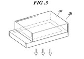
- Schematic diagram of a passive matrix display device Schematic of lighting device
- Cross section of the lighting device Schematic configuration diagram of organic EL full-color display device
- the inventors of the present invention are organic electroluminescent elements in which at least one light emitting layer is sandwiched between an anode and a cathode, and the intensity reduction rate of electroluminescence is reduced. It has been found that the intended effect is achieved when the contribution ratio of the light emitting layer defined by the ratio ⁇ PL / ⁇ EL of the intensity decay rate of photoluminescence is 0.3 or more and 1.0 or less. is there.
- ⁇ EL and ⁇ PL represent the intensity decay rates of electroluminescence (EL) and photoluminescence (PL) after driving, respectively, and can be represented by the following equations.
- ⁇ EL 1 ⁇ [EL (after driving) / EL (initial)]
- ⁇ PL 1 ⁇ [PL (after driving) / PL (initial)]
- the light emitting layer contribution ratio ⁇ PL / ⁇ EL is more preferably in the range of 0.4 to 1.0, and still more preferably in the range of 0.5 to 1.0.
- the upper limit is 1.0 or less.
- the light is efficiently emitted in the light emitting layer by being within the above-mentioned range.
- PL photoluminescence
- EL electroluminescence
- the contribution ratio of the light emitting layer defined above is an index that contributes to light emission excluding the local light emission portion such as the interface.
- the PL spectrum can be measured using USB2000 (manufactured by Ocean Optics) at 23 ° C. and an excitation wavelength of 365 nm. The measurement can be performed within 2 hours after the organic EL device is driven until the strength is reduced from the initial half.
- the target effect is more remarkable when the light emitting layer is thicker, and is preferably in the range of 20 to 150 nm, particularly preferably in the range of 50 to 130 nm.
- the light emitting layer may be a single layer or a plurality of layers, but a single layer is preferable from the viewpoint of ⁇ PL / ⁇ EL and chromaticity stability. It is presumed that these aspects have a great effect of reducing local light emission by EL driving.
- the objective effect is remarkable by using the compounds represented by the general formula (1) and the general formula (2), and it is preferable to use them in combination.
- UV light deterioration resistance ratio PL (after UV light irradiation) / PL (before UV light irradiation), and only a light emitting layer is formed on a quartz substrate with a thickness of 50 nm.
- a spot light source / lightening cure LC8 manufactured by Hamamatsu Photonics is used to irradiate light having an emission maximum at 365 nm 1 cm, 20 min.
- the output of the spot light source was adjusted so that the number of absorbed fonts was constant in each element.
- the maximum absorption wavelength of the phosphorescent blue light-emitting dopant in the present invention is about 365 nm, the evaluation was performed with the irradiation light of 365 nm unified.
- UV light deterioration ratio value is 0.6 or more, not only the long life but also the effect on chromaticity stability is great.
- This value is considered to be related to delocalization of the light emitting portion other than the interface of the light emitting layer in EL driving, and is preferably 0.7 or more and the upper limit is 1.0 or less.
- the light emitting layer is adjacent to the hole transport layer.
- the IP of at least one phosphorescent compound contained in the light emitting layer is in the range of ⁇ 0.3 to 0.2 eV with respect to the IP of at least one hole transporting material contained in the hole transporting layer. It is preferable to be within. In this case, it has surprisingly been found that it is effective in reducing defective light emission (dark spots).
- At least one phosphorescent compound is a dopant having the smallest IP, and this is because a dopant having the smallest IP among the dopants contained in the light emitting layer is likely to be a carrier trap. This is because the influence on the device performance is great.
- the dopant having the smallest IP is preferably a blue light emitting dopant when a phosphorescent compound used in a multicolor organic electroluminescence device that emits white light is used in the same layer. This is because energy transfer from the highest triplet excited blue light-emitting material to the green / red light-emitting material occurs due to one of the white light emission principles.
- a hole injection layer is provided between the anode and the hole transport layer, and the IP of the hole injection layer is within a range of ⁇ 0.2 to 0.3 eV with respect to the work function of the anode. In addition, it is also a preferable aspect that it is in a range of ⁇ 0.3 to 0.2 eV with respect to IP of at least one hole transport material contained in the hole transport layer.
- the ionization potential is defined by the energy required to emit electrons at the HOMO (highest occupied orbital) level of the compound to the vacuum level, and can be obtained by the following method in the present invention.
- the ionization potential can be determined by a method of direct measurement by photoelectron spectroscopy.
- a low energy electron spectrometer “Model AC-1” manufactured by Riken Keiki Co., Ltd., an ESCA 5600 UPS (ultraviolet photoemission spectroscopy) manufactured by ULVAC-PHI, or a method known as ultraviolet photoelectron spectroscopy is suitable.
- ESCA 5600 UPS ultraviolet photoelectron spectroscopy
- the ionization potential (maximum electron occupation level (HOMO) level) of the metal complex, hole transport material, and hole injection material in the present invention can be obtained by using, for example, ultraviolet photoelectron spectroscopy (UPS). That is, the IP value can be measured by measuring the UPS of a thin film of these compounds formed on a glass substrate.
- UPS ultraviolet photoelectron spectroscopy
- the metal complex represented by the said General formula (1) is a phosphorescence-emitting compound contained in the light emitting layer mentioned later.
- organometallic complex represented by the above general formula (1) is also a preferable aspect to contain an organometallic complex represented by the above general formula (1) as a hole transport material.
- R 1 represents a substituent.
- Z represents a nonmetallic atom group necessary for forming a 5- to 7-membered ring.
- n1 represents an integer of 0 to 5.
- B 1 to B 5 represent a carbon atom, a nitrogen atom, an oxygen atom or a sulfur atom, and at least one represents a nitrogen atom. These five atoms form a monocyclic aromatic nitrogen-containing heterocycle.
- M 1 represents a group 8-10 metal in the periodic table.
- X 1 and X 2 represent a carbon atom, a nitrogen atom or an oxygen atom, and L 1 represents an atomic group which forms a bidentate ligand together with X 1 and X 2 .
- m1 represents an integer of 1 to 3
- m2 represents an integer of 0 to 2
- m1 + m2 is 2 or 3.
- Examples of the substituent represented by R 1 include an alkyl group (eg, methyl group, ethyl group, propyl group, isopropyl group, tert-butyl group, pentyl group, hexyl group, octyl group, dodecyl group, tridecyl group, tetradecyl group).
- an alkyl group eg, methyl group, ethyl group, propyl group, isopropyl group, tert-butyl group, pentyl group, hexyl group, octyl group, dodecyl group, tridecyl group, tetradecyl group.
- cycloalkyl group eg, cyclopentyl group, cyclohexyl group, etc.
- alkenyl group eg, vinyl group, allyl group, etc.
- alkynyl group eg, ethynyl group, propargyl group, etc.
- aromatic carbonization Hydrogen ring group also called aromatic carbocyclic group, aryl group, etc., for example, phenyl group, p-chlorophenyl group, mesityl group, tolyl group, xylyl group, naphthyl group, anthryl group, azulenyl group, acenaphthenyl group, fluorenyl group, Phenanthryl, indenyl, pyrenyl, biphenylyl, etc.), aromatic A cyclic group (for example, pyridyl group, pyrimidinyl group, furyl group, pyr
- a plurality of R 1 may be bonded to each other to form a condensed ring.
- alkyl group and an aryl group are preferred. More preferred is an unsubstituted alkyl group or aryl group.
- Z represents a nonmetallic atom group necessary for forming a 5- to 7-membered ring.
- the 5- to 7-membered ring formed by Z include a benzene ring, naphthalene ring, pyridine ring, pyrimidine ring, pyrrole ring, thiophene ring, pyrazole ring, imidazole ring, oxazole ring and thiazole ring. Of these, a benzene ring is preferred.
- B 1 to B 5 represent a carbon atom, a nitrogen atom, an oxygen atom or a sulfur atom, and at least one represents a nitrogen atom.
- Examples of the monocyclic aromatic nitrogen-containing heterocycle formed by these five atoms include a pyrrole ring, a pyrazole ring, an imidazole ring, a triazole ring, a tetrazole ring, an oxazole ring, an isoxazole ring, a thiazole ring, and an isothiazole ring.
- Oxadiazole ring and thiadiazol ring are preferable, and an imidazole ring is more preferable.
- the aromatic nitrogen-containing heterocycle formed by these five atoms may have a substituent.
- substituents include the same substituent as R 1 described above.
- a plurality of substituents may be bonded to each other to form a condensed ring.
- the substituent may be bonded to a 5- to 7-membered ring containing Z to form a condensed 3-ring ring.
- L 1 represents an atomic group that forms a bidentate ligand together with X 1 and X 2 .
- Specific examples of the bidentate ligand represented by X 1 -L 1 -X 2 include, for example, substituted or unsubstituted phenylpyridine, phenylpyrazole, phenylimidazole, phenyltriazole, phenyltetrazole, pyrazabol and acetylacetone. Is mentioned. These groups may be further substituted with the above substituents.
- M1 represents an integer of 1 to 3
- m2 represents an integer of 0 to 2
- m1 + m2 is 2 or 3.
- m2 is preferably 0.
- a transition metal element belonging to Group 8 to 10 of the periodic table (also simply referred to as a transition metal) is used, among which iridium and platinum are preferable, and iridium is more preferable.
- the light emitting layer containing a phosphorescence-emitting compound contains the compound represented by General formula (2).
- R 20 represents a hydrogen atom or a substituent. At least one of R 20 is represented by the following general formula: (Represented by the formula (b1))
- L 20 represents a divalent linking group derived from an aromatic hydrocarbon ring or an aromatic heterocyclic ring.
- N23 represents 0 or an integer of 1 to 3, and when n23 is 2 or more, a plurality of L 20 May be the same or different, * represents a linking site with the mother nucleus of the general formula (2), Ar 20 represents a group represented by the following general formula (b2).
- the compound represented by the general formula (2) is a 6-membered aromatic heterocycle containing at least one nitrogen atom in the molecule, or at least one nitrogen as one of the rings constituting the condensed ring. It has a condensed ring having a 6-membered aromatic heterocyclic ring containing an atom.
- Anode / light emitting layer / electron transport layer / cathode ii) Anode / hole transport layer / light emitting layer / electron transport layer / cathode (iii) Anode / hole transport layer / light emitting layer / hole blocking layer / electron Transport layer / cathode (iv) Anode / hole transport layer / light emitting layer / hole blocking layer / electron transport layer / cathode buffer layer / cathode (v) Anode / hole injection layer / hole transport layer / light emitting layer / positive Hole blocking layer / electron transport layer / cathode buffer layer / cathode (vi) anode / hole injection layer / hole transport layer / light emitting layer / hole blocking layer / electron transport layer / cathode buffer layer / cathode (vii) anode / Hole injection layer / hole transport layer / light emitting layer / electron transport layer / cathode
- a non-light emitting intermediate layer may be provided between the light emitting layers, and the intermediate layer may include a charge generation layer.
- the organic EL element of the present invention is preferably a white light emitting layer, and is preferably a lighting device using these.
- the light-emitting layer according to the present invention is a layer that emits light by recombination of electrons and holes injected from the electrode, the electron transport layer, or the hole transport layer, and the light-emitting portion is within the light-emitting layer and the light-emitting layer And the interface between adjacent layers.
- the total thickness of the light-emitting layer is not particularly limited, but it is possible to prevent film homogeneity and application of unnecessary high voltage during light emission, and to improve the chromaticity of the emitted color. Therefore, it is preferably in the range of 20 to 150 nm, particularly preferably in the range of 50 to 130 nm.
- a light emitting dopant or host compound described later is used, for example, a vacuum deposition method, a wet method (also referred to as a wet process, for example, a spin coating method, a casting method, a die coating method, a blade coating method, a roll coating method,
- the film can be formed by an inkjet method, a printing method, a spray coating method, a curtain coating method, an LB method (including Langmuir-Blodgett method)) and the like.
- LB method including Langmuir-Blodgett method
- the light emitting layer of the organic EL device of the present invention preferably contains a light emitting dopant and a host compound.
- Luminescent dopant A light-emitting dopant (also referred to as a dopant) will be described.
- a fluorescent luminescent dopant also referred to as a fluorescent dopant
- a phosphorescent compound also referred to as a phosphorescent luminescent dopant or a phosphorescent dopant
- the phosphorescent dopant according to the present invention is a compound in which light emission from an excited triplet is observed, specifically, a compound that emits phosphorescence at room temperature (25 ° C.), and a phosphorescence quantum yield is 25 ° C.
- the phosphorescence quantum yield is preferably 0.1 or more.
- the phosphorescent quantum yield can be measured by the method described in Spectroscopic II, page 398 (1992 edition, Maruzen) of the Fourth Edition Experimental Chemistry Course 7. Although the phosphorescence quantum yield in a solution can be measured using various solvents, the phosphorescence dopant according to the present invention achieves the phosphorescence quantum yield (0.01 or more) in any solvent. That's fine.
- phosphorescent dopants There are two types of emission of phosphorescent dopants in principle. One is the recombination of carriers on the host compound to which carriers are transported to generate an excited state of the host compound, and this energy is transferred to the phosphorescent dopant. Energy transfer type to obtain light emission from the phosphorescent dopant, and the other is that the phosphorescent dopant becomes a carrier trap, carrier recombination occurs on the phosphorescent dopant, and light emission from the phosphorescent dopant compound is obtained. In either case, the excited state energy of the phosphorescent dopant is required to be lower than the excited state energy of the host compound.
- the light-emitting layer according to the present invention may be used in combination with compounds described in the following patent publications.
- JP 2002-280178 A JP 2001-181616 A, JP 2002-280179 A, JP 2001-181617 A, JP 2002-280180 A.
- JP-A-2001-247859, JP-A-2002-299060 JP-A-2001-313178, JP-A-2002-302671, JP-A-2001-345183, JP-A-2002-324679, international JP 02/15645 pamphlet, JP 2002-332291 A, JP 2002-50484 A, JP 2002-332292 A, JP 2002-83684 A, JP 2002-540572 A, JP No.
- fluorescent dopant As fluorescent dopants, coumarin dyes, pyran dyes, cyanine dyes, croconium dyes, squalium dyes, oxobenzanthracene dyes, fluorescein dyes, rhodamine dyes, pyrylium dyes, perylene dyes, stilbene dyes , Polythiophene dyes, rare earth complex phosphors, and the like, and compounds having a high fluorescence quantum yield represented by laser dyes.
- the light-emitting dopant according to the present invention may be used in combination of a plurality of types of compounds, or may be a combination of phosphorescent dopants having different structures, or a combination of a phosphorescent dopant and a fluorescent dopant.
- the light emitting layer preferably contains at least one phosphorescent compound.
- the organic EL device of the present invention preferably emits white light, and a light emitting dopant and a host compound can be used in appropriate combination so as to achieve the preferred chromaticity as the white device described above.
- the luminescent dopant is preferably a phosphorescent compound, and at least one of the phosphorescent compounds preferably has an emission maximum of 480 nm or less. It is more preferable to have an emission maximum at 400 nm to 480 nm.
- the luminescent dopant is particularly preferably the compound represented by the general formula (1) described above as the phosphorescent compound.
- the light emitting layer is formed containing a phosphorescent compound selected from the general formula (1) and a compound selected from the general formula (2).
- the light emitting layer may be a single layer or a plurality of layers, but a single layer is preferred.
- the host compound has a mass ratio of 20% or more among the compounds contained in the light emitting layer, and a phosphorescence quantum yield of phosphorescence emission is 0 at room temperature (25 ° C.). Defined as less than 1 compound.
- the phosphorescence quantum yield is preferably less than 0.01.
- the mass ratio in the layer is 20% or more among the compounds contained in a light emitting layer.
- the light-emitting host that can be used in the present invention is not particularly limited, and compounds conventionally used in organic EL devices can be used.
- a compound that has a hole transporting ability and an electron transporting ability, prevents the emission of light from being increased in wavelength, and has a high Tg (glass transition temperature) is preferable.
- the luminescent host (the compound represented by the general formula (2) according to the present invention and / or a known luminescent host) may be used alone or in combination of two or more. Good.
- the light emitting host used in the present invention may be a low molecular compound, a high molecular compound having a repeating unit, or a low molecular compound having a polymerizable group such as a vinyl group or an epoxy group (polymerizable light emitting host).
- a polymerizable group such as a vinyl group or an epoxy group (polymerizable light emitting host).
- one or a plurality of such compounds may be used.
- the light emitting host of the light emitting layer of the organic EL device of the present invention is the compound represented by the general formula (2) according to the present invention described above.
- the hole transport layer is made of a hole transport material having a function of transporting holes, and in a broad sense, a hole injection layer and an electron blocking layer are also included in the hole transport layer.
- the hole transport layer can be provided as a single layer or a plurality of layers.
- the hole transport material has any of hole injection or transport and electron barrier properties, and may be either organic or inorganic.
- triazole derivatives oxadiazole derivatives, imidazole derivatives, polyarylalkane derivatives, pyrazoline derivatives and pyrazolone derivatives, phenylenediamine derivatives, arylamine derivatives, amino-substituted chalcone derivatives, oxazole derivatives, styrylanthracene derivatives, fluorenone derivatives, hydrazone derivatives
- Examples include stilbene derivatives, silazane derivatives, aniline copolymers, conductive polymer oligomers (particularly thiophene oligomers), and organometallic complexes.
- the above-mentioned materials can be used as the hole transport material, porphyrin compounds, aromatic tertiary amine compounds and styrylamine compounds, and organometallic complexes are preferable, and aromatic tertiary amine compounds and organic compounds are more preferable. It is preferable to use an organometallic complex as the metal complex.
- aromatic tertiary amine compounds and styrylamine compounds include N, N, N ′, N′-tetraphenyl-4,4′-diaminophenyl; N, N′-diphenyl-N, N′— Bis (3-methylphenyl)-[1,1′-biphenyl] -4,4′-diamine (TPD); 2,2-bis (4-di-p-tolylaminophenyl) propane; 1,1-bis (4-di-p-tolylaminophenyl) cyclohexane; N, N, N ′, N′-tetra-p-tolyl-4,4′-diaminobiphenyl; 1,1-bis (4-di-p-tolyl) Aminophenyl) -4-phenylcyclohexane; bis (4-dimethylamino-2-methylphenyl) phenylmethane; bis (4-di-p-tolylaminoph
- No. 5,061,569 Having a condensed aromatic ring of, for example, 4,4'-bis [N- (1-naphthyl) -N-phenylamino] biphenyl (NPD), JP-A-4-308 4,4 ′, 4 ′′ -tris [N- (3-methylphenyl) -N-phenylamino] triphenylamine in which three triphenylamine units described in Japanese Patent No. 88 are linked in a starburst type ( MTDATA) and the like.
- NPD 4,4'-bis [N- (1-naphthyl) -N-phenylamino] biphenyl
- JP-A-4-308 4,4 ′, 4 ′′ -tris [N- (3-methylphenyl) -N-phenylamino] triphenylamine in which three triphenylamine units described in Japanese Patent No. 88 are linked in a starburst type ( MTDATA) and the
- the organometallic complex is preferably an organometallic complex represented by the general formula (1).
- a polymer material in which these materials are introduced into a polymer chain or these materials are used as a polymer main chain can also be used.
- inorganic compounds such as p-type-Si and p-type-SiC can be used as the hole injection material and the hole transport material.
- JP-A-11-251067, J. Org. Huang et. al. A so-called p-type hole transport material as described in a book (Applied Physics Letters 80 (2002), p. 139) can also be used. In the present invention, these materials are preferably used because a light-emitting element with higher efficiency can be obtained.
- the hole transport layer can be formed by thinning the hole transport material by a known method such as a vacuum deposition method, a spin coating method, a casting method, a printing method including an ink jet method, or an LB method. it can.
- the film thickness of the hole transport layer is not particularly limited, but is usually about 5 nm to 5 ⁇ m, preferably 5 nm to 200 nm.
- the hole transport layer may have a single layer structure composed of one or more of the above materials.
- a hole transport layer having a high p property doped with impurities examples thereof include JP-A-4-297076, JP-A-2000-196140, JP-A-2001-102175, J. Pat. Appl. Phys. 95, 5773 (2004), and the like.
- a hole transport layer having such a high p property because a device with lower power consumption can be produced.
- ⁇ Blocking layer hole blocking layer, electron blocking layer>
- the blocking layer is provided as necessary in addition to the basic constituent layer of the organic compound thin film as described above. For example, it is described in JP-A Nos. 11-204258 and 11-204359, and “Organic EL elements and the forefront of industrialization (published by NTT Corporation on November 30, 1998)” on page 237. There is a hole blocking (hole blocking) layer.
- the hole blocking layer has a function of an electron transport layer in a broad sense, and is made of a hole blocking material that has a function of transporting electrons and has a remarkably small ability to transport holes. The probability of recombination of electrons and holes can be improved by blocking.
- the above-described configuration of the electron transport layer can be used as a hole blocking layer according to the present invention, if necessary.
- the hole blocking layer of the organic EL device of the present invention is preferably provided adjacent to the light emitting layer.
- the carbazole derivatives and azacarbazole derivatives mentioned above as the host compounds (where azacarbazole derivatives are those in which one or more carbon atoms constituting the carbazole ring are replaced by nitrogen atoms) Preferably).
- the light emitting layer having the shortest wavelength of light emission is preferably closest to the anode among all the light emitting layers.
- 50% by mass or more of the compound contained in the hole blocking layer provided at the position has an ionization potential of 0.3 eV or more larger than the host compound of the shortest wave emitting layer.
- the electron blocking layer has a function of a hole transport layer in a broad sense, and is made of a material that has a function of transporting holes and has an extremely small ability to transport electrons, and transports electrons while transporting holes. By blocking, the recombination probability of electrons and holes can be improved.
- the above-described configuration of the hole transport layer can be used as an electron blocking layer as necessary.
- the film thicknesses of the hole blocking layer and the electron blocking layer according to the present invention are preferably in the range of 3 nm to 100 nm, and more preferably in the range of 3 nm to 30 nm.
- Injection layer electron injection layer (cathode buffer layer), hole injection layer >> The injection layer is provided as necessary, and there are an electron injection layer and a hole injection layer, and as described above, it exists between the anode and the light emitting layer or the hole transport layer, and between the cathode and the light emitting layer or the electron transport layer. May be.
- An injection layer is a layer provided between an electrode and an organic layer in order to reduce drive voltage and improve light emission luminance.
- Organic EL element and its forefront of industrialization (issued by NTT Corporation on November 30, 1998) ) ”, Chapter 2,“ Electrode Materials ”(pages 123 to 166), which has a hole injection layer (anode buffer layer) and an electron injection layer (cathode buffer layer).
- hole injection layer anode buffer layer
- copper phthalocyanine is used.
- examples thereof include a phthalocyanine buffer layer represented by an oxide, an oxide buffer layer represented by vanadium oxide, an amorphous carbon buffer layer, and a polymer buffer layer using a conductive polymer such as polyaniline (emeraldine) or polythiophene.
- a hole injection layer is preferably provided between the anode and the hole transport layer.
- the electron injection layer (cathode buffer layer) is also described in JP-A-6-325871, JP-A-9-17574, JP-A-10-74586, and the like. Specifically, strontium, aluminum, etc.
- Metal buffer layer typified by, alkali metal compound buffer layer typified by lithium fluoride, sodium fluoride, potassium fluoride, etc., alkaline earth metal compound buffer layer typified by magnesium fluoride, and aluminum oxide And an oxide buffer layer.
- the buffer layer (injection layer) is preferably a very thin film, and the film thickness is preferably in the range of 0.1 nm to 5 ⁇ m, although it depends on the material.
- the materials used for the hole injection layer (anode buffer layer) and the cathode buffer layer can be used in combination with other materials, for example, mixed in the hole transport layer or the electron transport layer. It is also possible.
- the electron transport layer is made of a material having a function of transporting electrons, and in a broad sense, an electron injection layer and a hole blocking layer are also included in the electron transport layer.
- the electron transport layer can be provided with a single layer or a plurality of layers.
- An electron transport material (including a hole blocking material and an electron injection material) used for the electron transport layer only needs to have a function of transmitting electrons injected from the cathode to the light emitting layer.
- electron transport materials examples include heterocyclic tetracarboxylic acid anhydrides such as nitro-substituted fluorene derivatives, diphenylquinone derivatives, thiopyran dioxide derivatives, naphthalene perylene, And azacarbazole derivatives including carbodiimide, fluorenylidenemethane derivatives, anthraquinodimethane and anthrone derivatives, oxadiazole derivatives, carboline derivatives, and the like.
- heterocyclic tetracarboxylic acid anhydrides such as nitro-substituted fluorene derivatives, diphenylquinone derivatives, thiopyran dioxide derivatives, naphthalene perylene, And azacarbazole derivatives including carbodiimide, fluorenylidenemethane derivatives, anthraquinodimethane and anthrone derivatives, oxadiazole derivatives, carboline derivatives
- the azacarbazole derivative means one in which one or more carbon atoms constituting the carbazole ring are replaced with nitrogen atoms.
- a thiadiazole derivative in which the oxygen atom of the oxadiazole ring is substituted with a sulfur atom, and a quinoxaline derivative having a quinoxaline ring known as an electron-withdrawing group can also be used as an electron transport material.
- metal complexes of 8-quinolinol derivatives such as tris (8-quinolinol) aluminum (Alq), tris (5,7-dichloro-8-quinolinol) aluminum, tris (5,7-dibromo-8-quinolinol) aluminum Tris (2-methyl-8-quinolinol) aluminum, tris (5-methyl-8-quinolinol) aluminum, bis (8-quinolinol) zinc (Znq), and the like, and the central metals of these metal complexes are In, Mg, Metal complexes replaced with Cu, Ca, Sn, Ga, or Pb can also be used as the electron transport material.
- metal-free or metal phthalocyanine or those in which the terminal is substituted with an alkyl group or a sulfonic acid group can also be used as the electron transport material.
- inorganic semiconductors such as n-type-Si and n-type-SiC can also be used as the electron transport material.
- the electron transport layer is made of an electron transport material such as a vacuum deposition method, a wet method (also called a wet process, such as a spin coating method, a casting method, a die coating method, a blade coating method, a roll coating method, an ink jet method, a printing method, It is preferable to form the film by a coating method, a curtain coating method, an LB method (such as Langmuir's Blodgett method)).
- a wet method also called a wet process, such as a spin coating method, a casting method, a die coating method, a blade coating method, a roll coating method, an ink jet method, a printing method
- LB method such as Langmuir's Blodgett method
- the thickness of the electron transport layer is not particularly limited, but is usually in the range of about 5 nm to 5000 nm, preferably 5 nm to 200 nm.
- the electron transport layer may have a single layer structure composed of one or more of the above materials.
- an electron transport layer having a high n property doped with impurities examples thereof include JP-A-4-297076, JP-A-10-270172, JP-A-2000-196140, 2001-102175, J.A. Appl. Phys. 95, 5773 (2004), and the like.
- anode As the anode in the organic EL element, an electrode material made of a metal, an alloy, an electrically conductive compound, or a mixture thereof having a high work function (4 eV or more) is preferably used. Specific examples of such electrode substances include metals such as Au, and conductive transparent materials such as CuI, indium tin oxide (ITO), SnO 2 , and ZnO.
- an amorphous material such as IDIXO (In 2 O 3 —ZnO) that can form a transparent conductive film may be used.
- the anode may be formed by depositing a thin film of these electrode materials by vapor deposition or sputtering, and a pattern having a desired shape may be formed by photolithography, or when pattern accuracy is not so high (about 100 ⁇ m or more) A pattern may be formed through a mask having a desired shape at the time of vapor deposition or sputtering of the electrode material.
- a wet film forming method such as a printing method or a coating method can be used.
- the transmittance be greater than 10%, and the sheet resistance as the anode is preferably several hundred ⁇ / ⁇ or less.
- the film thickness depends on the material, it is usually selected in the range of 10 nm to 1000 nm, preferably 10 nm to 200 nm.
- cathode a material having a low work function (4 eV or less) metal (referred to as an electron injecting metal), an alloy, an electrically conductive compound, and a mixture thereof as an electrode material is used.
- electrode materials include sodium, sodium-potassium alloy, magnesium, lithium, magnesium / copper mixture, magnesium / silver mixture, magnesium / aluminum mixture, magnesium / indium mixture, aluminum / aluminum oxide (Al 2 O 3 ) Mixtures, indium, lithium / aluminum mixtures, rare earth metals and the like.
- a mixture of an electron injecting metal and a second metal which is a stable metal having a larger work function than this for example, a magnesium / silver mixture
- a magnesium / aluminum mixture a magnesium / aluminum mixture, a magnesium / indium mixture, an aluminum / aluminum oxide (Al 2 O 3 ) mixture, a lithium / aluminum mixture, aluminum and the like.
- the cathode can be produced by forming a thin film of these electrode materials by a method such as vapor deposition or sputtering.
- the sheet resistance as the cathode is preferably several hundred ⁇ / ⁇ or less, and the film thickness is usually selected in the range of 10 nm to 5 ⁇ m, preferably 50 nm to 200 nm.
- the emission luminance is advantageously improved.
- a transparent or translucent cathode can be manufactured by forming the above metal on the cathode with a film thickness in the range of 1 nm to 20 nm and then forming the conductive transparent material mentioned in the description of the anode thereon.
- an element in which both the anode and the cathode are transmissive can be manufactured.
- the support substrate (hereinafter also referred to as a substrate) that can be used in the organic EL device of the present invention is not particularly limited in the type of glass, plastic, and the like, and may be transparent or opaque.
- the support substrate is preferably transparent.
- the transparent support substrate preferably used include glass, quartz, and a transparent resin film.
- a particularly preferable support substrate is a resin film capable of giving flexibility to the organic EL element.
- polyesters such as polyethylene terephthalate (PET) and polyethylene naphthalate (PEN), polyethylene, polypropylene, cellophane, cellulose diacetate, cellulose triacetate, cellulose acetate butyrate, cellulose acetate propionate (CAP), Cellulose esters such as cellulose acetate phthalate (TAC) and cellulose nitrate or derivatives thereof, polyvinylidene chloride, polyvinyl alcohol, polyethylene vinyl alcohol, syndiotactic polystyrene, polycarbonate, norbornene resin, polymethylpentene, polyether ketone, polyimide , Polyethersulfone (PES), polyphenylene sulfide, polysulfones Cycloolefin resins such as polyetherimide, polyetherketoneimide, polyamide, fluororesin, nylon, polymethylmethacrylate, acrylic or polyarylate, Arton (trade name, manufactured by JSR) or Appel (
- the surface of the resin film may be formed with an inorganic film, an organic film, or a hybrid film of both, and the water vapor permeability (25 ⁇ 0.5 ° C.) measured by a method according to JIS K 7129-1992.
- Relative humidity (90 ⁇ 2)% RH) is preferably 0.01 g / (m 2 ⁇ 24 h) or less, and oxygen measured by a method according to JIS K 7126-1987.
- a high barrier film having a permeability of 10 ⁇ 3 ml / (m 2 ⁇ 24 h ⁇ atm) or less and a water vapor permeability of 10 ⁇ 5 g / (m 2 ⁇ 24 h) or less is preferable.
- the material for forming the barrier film may be any material that has a function of suppressing the intrusion of elements that cause deterioration of elements such as moisture and oxygen.
- silicon oxide, silicon dioxide, silicon nitride, or the like can be used.
- the method for forming the barrier film is not particularly limited.
- the vacuum deposition method, sputtering method, reactive sputtering method, molecular beam epitaxy method, cluster ion beam method, ion plating method, plasma polymerization method, atmospheric pressure plasma weight A combination method, a plasma CVD method, a laser CVD method, a thermal CVD method, a coating method, and the like can be used, but an atmospheric pressure plasma polymerization method as described in JP-A-2004-68143 is particularly preferable.
- the opaque support substrate examples include metal plates such as aluminum and stainless steel, films, opaque resin substrates, ceramic substrates, and the like.
- the external extraction efficiency at room temperature of light emission of the organic EL element of the present invention is preferably 1% or more, more preferably 5% or more.
- the external extraction quantum efficiency (%) the number of photons emitted to the outside of the organic EL element / the number of electrons sent to the organic EL element ⁇ 100.
- a hue improvement filter such as a color filter may be used in combination, or a color conversion filter that converts the emission color from the organic EL element into multiple colors using a phosphor may be used in combination.
- a desired electrode material for example, a thin film made of an anode material is formed on a suitable substrate so as to have a film thickness of 1 ⁇ m or less, preferably in the range of 10 nm to 200 nm, thereby producing an anode.
- a thin film containing an organic compound such as a hole injection layer, a hole transport layer, a light emitting layer, a hole blocking layer, an electron transport layer, or a cathode buffer layer, which is an element material, is formed thereon.
- the layer containing the compound represented by the general formula (2) is applied and formed by a wet method.
- Wet methods include spin coating, casting, die coating, blade coating, roll coating, ink jet, printing, spray coating, curtain coating, and LB, but precise thin films can be formed.
- a method having high suitability for a roll-to-roll method such as a die coating method, a roll coating method, an ink jet method, or a spray coating method is preferable. Different film forming methods may be applied for each layer.
- liquid medium for dissolving or dispersing the organic EL material according to the present invention examples include ketones such as methyl ethyl ketone and cyclohexanone, fatty acid esters such as ethyl acetate, halogenated hydrocarbons such as dichlorobenzene, toluene, xylene, and mesitylene.
- ketones such as methyl ethyl ketone and cyclohexanone
- fatty acid esters such as ethyl acetate
- halogenated hydrocarbons such as dichlorobenzene, toluene, xylene, and mesitylene.
- Aromatic hydrocarbons such as cyclohexylbenzene, aliphatic hydrocarbons such as cyclohexane, decalin, and dodecane
- organic solvents such as DMF and DMSO
- a dispersion method it can be dispersed by a dispersion method such as ultrasonic wave, high shearing force dispersion or media dispersion.
- a thin film made of a cathode material is formed thereon so as to have a thickness of 1 ⁇ m or less, preferably in the range of 50 to 200 nm, and a desired organic EL device can be obtained by providing a cathode. .
- the cathode, cathode buffer layer, electron transport layer, hole blocking layer, light emitting layer, hole transport layer, hole injection layer, and anode can be formed in the reverse order.
- a DC voltage When a DC voltage is applied to the multicolor display device obtained in this way, light emission can be observed by applying a voltage of about 2V to 40V with the positive polarity of the anode and the negative polarity of the cathode.
- An alternating voltage may be applied.
- the alternating current waveform to be applied may be arbitrary.
- the production of the organic EL device of the present invention is preferably produced from the hole injection layer to the cathode consistently by a single evacuation, but it may be taken out halfway and subjected to different film forming methods. At that time, it is preferable to perform the work in a dry inert gas atmosphere.
- ⁇ Sealing> As a sealing means used for this invention, the method of adhere
- the sealing member may be disposed so as to cover the display area of the organic EL element, and may be a concave plate shape or a flat plate shape. Further, transparency and electrical insulation are not particularly limited.
- Specific examples include a glass plate, a polymer plate / film, and a metal plate / film.
- the glass plate include soda-lime glass, barium / strontium-containing glass, lead glass, aluminosilicate glass, borosilicate glass, barium borosilicate glass, and quartz.
- examples of the polymer plate include polycarbonate, acrylic, polyethylene terephthalate, polyether sulfide, polysulfone and the like.
- examples of the metal plate include those made of one or more metals or alloys selected from the group consisting of stainless steel, iron, copper, aluminum, magnesium, nickel, zinc, chromium, titanium, molybdenum, silicon, germanium, and tantalum.
- a polymer film and a metal film can be preferably used because the element can be thinned.
- the polymer film has an oxygen permeability measured by a method according to JIS K 7126-1987 of 1 ⁇ 10 ⁇ 3 ml / (m 2 ⁇ 24 h ⁇ atm) or less, and a method according to JIS K 7129-1992. It is preferable that the water vapor permeability (25 ⁇ 0.5 ° C., relative humidity (90 ⁇ 2)% RH) measured in (1) is 1 ⁇ 10 ⁇ 3 g / (m 2 ⁇ 24 h) or less.
- sealing member For processing the sealing member into a concave shape, sandblasting, chemical etching, or the like is used.
- the adhesive include photocuring and thermosetting adhesives having reactive vinyl groups of acrylic acid oligomers and methacrylic acid oligomers, and moisture curing adhesives such as 2-cyanoacrylates. be able to.
- hot-melt type polyamide, polyester, and polyolefin can be mentioned.
- a cationic curing type ultraviolet curing epoxy resin adhesive can be mentioned.
- an organic EL element may deteriorate by heat processing, what can be adhesively cured from room temperature to 80 ° C. is preferable.
- a desiccant may be dispersed in the adhesive.
- coating of the adhesive agent to a sealing part may use commercially available dispenser, and may print like screen printing.
- the electrode and the organic layer are coated on the outside of the electrode facing the support substrate with the organic layer interposed therebetween, and an inorganic or organic layer is formed in contact with the support substrate to form a sealing film.
- the material for forming the film may be any material that has a function of suppressing intrusion of elements that cause deterioration of elements such as moisture and oxygen.
- silicon oxide, silicon dioxide, silicon nitride, or the like may be used. it can.
- the method for forming these films is not particularly limited.
- a polymerization method, a plasma CVD method, a laser CVD method, a thermal CVD method, a coating method, or the like can be used.
- an inert gas such as nitrogen or argon, or an inert liquid such as fluorinated hydrocarbon or silicon oil can be injected in the gas phase and liquid phase.
- an inert gas such as nitrogen or argon, or an inert liquid such as fluorinated hydrocarbon or silicon oil
- a vacuum is also possible.
- a hygroscopic compound can also be enclosed inside.
- hygroscopic compound examples include metal oxides (for example, sodium oxide, potassium oxide, calcium oxide, barium oxide, magnesium oxide, aluminum oxide) and sulfates (for example, sodium sulfate, calcium sulfate, magnesium sulfate, cobalt sulfate).
- metal oxides for example, sodium oxide, potassium oxide, calcium oxide, barium oxide, magnesium oxide, aluminum oxide
- sulfates for example, sodium sulfate, calcium sulfate, magnesium sulfate, cobalt sulfate.
- metal halides eg calcium chloride, magnesium chloride, cesium fluoride, tantalum fluoride, cerium bromide, magnesium bromide, barium iodide, magnesium iodide etc.
- perchloric acids eg perchloric acid Barium, magnesium perchlorate, and the like
- anhydrous salts are preferably used in sulfates, metal halides, and perchloric acids.
- a protective film or a protective plate may be provided on the outer side of the sealing film on the side facing the support substrate with the organic layer interposed therebetween or on the sealing film.
- the mechanical strength is not necessarily high. Therefore, it is preferable to provide such a protective film and a protective plate.
- the same glass plate, polymer plate / film, metal plate / film, and the like used for the sealing can be used, but the polymer film is light and thin. Is preferably used.
- the organic EL element emits light inside a layer having a refractive index higher than that of air (refractive index is about 1.7 to 2.1) and can extract only about 15% to 20% of the light generated in the light emitting layer. It is generally said. This is because light incident on the interface (interface between the transparent substrate and air) at an angle ⁇ greater than the critical angle causes total reflection and cannot be taken out of the device, or between the transparent electrode or light emitting layer and the transparent substrate. This is because the light is totally reflected between the light and the light is guided through the transparent electrode or the light emitting layer, and as a result, the light escapes in the direction of the element side surface.
- a method of improving the light extraction efficiency for example, a method of forming irregularities on the surface of the transparent substrate and preventing total reflection at the transparent substrate and the air interface (US Pat. No. 4,774,435), A method for improving efficiency by giving light condensing property to a substrate (Japanese Patent Laid-Open No. 63-314795), a method of forming a reflective surface on the side surface of an element (Japanese Patent Laid-Open No. 1-220394), and light emission from the substrate A method of forming an antireflection film by introducing a flat layer having an intermediate refractive index between the bodies (Japanese Patent Laid-Open No.
- these methods can be used in combination with the organic EL device of the present invention.
- a method of introducing a flat layer having a lower refractive index than the substrate between the substrate and the light emitter, or a substrate, transparent A method of forming a diffraction grating between any layers of the electrode layer and the light emitting layer (including between the substrate and the outside) can be suitably used.
- the low refractive index layer examples include aerogel, porous silica, magnesium fluoride, and a fluorine-based polymer. Since the refractive index of the transparent substrate is generally about 1.5 to 1.7, the low refractive index layer preferably has a refractive index of about 1.5 or less. Further, it is preferably 1.35 or less.
- the thickness of the low refractive index medium is preferably at least twice the wavelength in the medium. This is because the effect of the low refractive index layer is diminished when the thickness of the low refractive index medium is about the wavelength of light and the electromagnetic wave that has exuded by evanescent enters the substrate.
- the method of introducing a diffraction grating into an interface or any medium that causes total reflection is characterized by a high effect of improving light extraction efficiency.
- This method uses the property that the diffraction grating can change the direction of light to a specific direction different from refraction by so-called Bragg diffraction such as first-order diffraction and second-order diffraction.
- Bragg diffraction such as first-order diffraction and second-order diffraction.
- light that cannot go out due to total reflection between layers, etc. is diffracted by introducing a diffraction grating into any layer or medium (inside a transparent substrate or transparent electrode). I want to take it out.
- the diffraction grating to be introduced has a two-dimensional periodic refractive index. This is because light emitted from the light-emitting layer is randomly generated in all directions, so in a general one-dimensional diffraction grating having a periodic refractive index distribution only in a certain direction, only light traveling in a specific direction is diffracted. Therefore, the light extraction efficiency does not increase so much.
- the refractive index distribution a two-dimensional distribution
- the light traveling in all directions is diffracted, and the light extraction efficiency is increased.
- the position where the diffraction grating is introduced may be in any interlayer or medium (in the transparent substrate or in the transparent electrode), but is preferably in the vicinity of the organic light emitting layer where light is generated.
- the period of the diffraction grating is preferably about 1/2 to 3 times the wavelength of light in the medium.
- the arrangement of the diffraction grating is preferably two-dimensionally repeated such as a square lattice, a triangular lattice, or a honeycomb lattice.
- the organic EL element of the present invention can be processed on a light extraction side of a substrate, for example, by providing a microlens array-like structure, or combined with a so-called condensing sheet, for example in a specific direction, for example, with respect to the element light emitting surface.
- a condensing sheet for example in a specific direction, for example, with respect to the element light emitting surface.
- quadrangular pyramids having a side of 30 ⁇ m and an apex angle of 90 degrees are arranged two-dimensionally on the light extraction side of the substrate.
- One side is preferably within a range of 10 ⁇ m to 100 ⁇ m. If it becomes smaller than this, the effect of diffraction will generate
- the condensing sheet it is possible to use, for example, a sheet that has been put to practical use in an LED backlight of a liquid crystal display device.
- a brightness enhancement film (BEF) manufactured by Sumitomo 3M Limited can be used.
- a triangle stripe having a vertex angle of 90 degrees and a pitch of 50 ⁇ m may be formed on the substrate, the vertex angle may be rounded, and the pitch may be changed randomly. Other shapes may be used.
- a light diffusion plate / film may be used in combination with the light collecting sheet.
- a diffusion film (light-up) manufactured by Kimoto Co., Ltd. can be used.
- the organic EL element of the present invention can be used as a display device, a display, and various light emission sources.
- lighting devices home lighting, interior lighting
- clock and liquid crystal backlights billboard advertisements, traffic lights, light sources of optical storage media, light sources of electrophotographic copying machines, light sources of optical communication processors, light
- the light source of a sensor etc. are mentioned, It is not limited to this, Especially, it can use effectively for the use as a backlight of a liquid crystal display device, and a light source for illumination.
- patterning may be performed by a metal mask, an ink jet printing method, or the like during film formation, if necessary.
- patterning only the electrode may be patterned, the electrode and the light emitting layer may be patterned, or the entire layer of the element may be patterned.
- a conventionally known method is used. Can do.
- the preferred chromaticity as a white element in the present invention is such that the correlated color temperature is in the range of 2500 K to 7000 K, and in the CIE1931 color system, the y value deviation from the black body radiation at each color temperature is 0.1 or less. is there.
- the display device of the present invention comprises the organic EL element of the present invention.
- the display device of the present invention may be single color or multicolor, but here, the multicolor display device will be described.
- a shadow mask is provided only at the time of forming a light emitting layer, and a film can be formed on one surface by vapor deposition, casting, spin coating, ink jet, printing, or the like.
- the method is not limited, but is preferably a vapor deposition method, an inkjet method, a spin coating method, or a printing method.
- the configuration of the organic EL element included in the display device is selected from the above-described configuration examples of the organic EL element as necessary.
- the manufacturing method of an organic EL element is as having shown in the one aspect
- a DC voltage When a DC voltage is applied to the obtained multicolor display device, light emission can be observed by applying a voltage of about 2V to 40V with the positive polarity of the anode and the negative polarity of the cathode. Further, even when a voltage is applied with the opposite polarity, no current flows and no light emission occurs. Further, when an AC voltage is applied, light is emitted only when the anode is in the + state and the cathode is in the-state.
- the alternating current waveform to be applied may be arbitrary.
- the multicolor display device can be used as a display device, a display, and various light sources.
- a display device or display full-color display is possible by using three types of organic EL elements of blue, red, and green light emission.
- Display devices and displays include televisions, personal computers, mobile devices, AV devices, teletext displays, information displays in automobiles, and the like. In particular, it may be used as a display device for reproducing still images and moving images, and the driving method when used as a display device for reproducing moving images may be either a simple matrix (passive matrix) method or an active matrix method.
- Light sources include home lighting, interior lighting, clock and liquid crystal backlights, billboard advertisements, traffic lights, light sources for optical storage media, light sources for electrophotographic copying machines, light sources for optical communication processors, light sources for optical sensors, etc.
- the present invention is not limited to these examples.
- FIG. 1 is a schematic view showing an example of a display device composed of organic EL elements. It is a schematic diagram of a display such as a mobile phone that displays image information by light emission of an organic EL element.
- the display 1 includes a display unit A having a plurality of pixels, a control unit B that performs image scanning of the display unit A based on image information, and the like.
- the control unit B is electrically connected to the display unit A, and sends a scanning signal and an image data signal to each of a plurality of pixels based on image information from the outside, and the pixels for each scanning line respond to the image data signal by the scanning signal.
- the image information is sequentially emitted to scan the image and display the image information on the display unit A.
- FIG. 2 is a schematic diagram of the display unit A.
- the display unit A has a wiring unit including a plurality of scanning lines 5 and data lines 6 and a plurality of pixels 3 on the substrate.
- the main members of the display unit A will be described below.
- the light emitted from the pixel 3 is extracted in the direction of the white arrow (downward).
- the scanning line 5 and the plurality of data lines 6 in the wiring portion are each made of a conductive material, and the scanning lines 5 and the data lines 6 are orthogonal to each other in a grid pattern and are connected to the pixels 3 at the orthogonal positions (details are illustrated). Not)
- the pixel 3 When the scanning signal is applied from the scanning line 5, the pixel 3 receives the image data signal from the data line 6 and emits light according to the received image data.
- a full color display can be achieved by appropriately arranging pixels in the red region, the green region, and the blue region on the same substrate.
- FIG. 3 is a schematic diagram of a pixel.
- the pixel includes an organic EL element 10, a switching transistor 11, a driving transistor 12, a capacitor 13, and the like.
- a full color display can be performed by using red, green, and blue light emitting organic EL elements as the organic EL elements 10 in a plurality of pixels, and juxtaposing them on the same substrate.
- an image data signal is applied from the control unit B to the drain of the switching transistor 11 via the data line 6.
- a scanning signal is applied from the control unit B to the gate of the switching transistor 11 via the scanning line 5
- the driving of the switching transistor 11 is turned on, and the image data signal applied to the drain is supplied to the capacitor 13 and the driving transistor 12. Is transmitted to the gate.
- the capacitor 13 is charged according to the potential of the image data signal, and the drive transistor 12 is turned on.
- the drive transistor 12 has a drain connected to the power supply line 7 and a source connected to the electrode of the organic EL element 10, and the power supply line 7 connects to the organic EL element 10 according to the potential of the image data signal applied to the gate. Current is supplied.
- the driving of the switching transistor 11 is turned off. However, even if the driving of the switching transistor 11 is turned off, the capacitor 13 maintains the potential of the charged image data signal, so that the driving of the driving transistor 12 is kept on and the next scanning signal is applied. Until then, the light emission of the organic EL element 10 continues.
- the driving transistor 12 is driven according to the potential of the next image data signal synchronized with the scanning signal, and the organic EL element 10 emits light.
- the light emission of the organic EL element 10 is performed by providing the switching transistor 11 and the drive transistor 12 which are active elements with respect to the organic EL element 10 of each of the plurality of pixels. It is carried out.
- Such a light emitting method is called an active matrix method.
- the light emission of the organic EL element 10 may be light emission of a plurality of gradations by a multi-value image data signal having a plurality of gradation potentials, or by turning on / off a predetermined light emission amount by a binary image data signal. Good.
- the potential of the capacitor 13 may be maintained until the next scanning signal is applied, or may be discharged immediately before the next scanning signal is applied.
- the present invention not only the active matrix method described above, but also a passive matrix light emission drive in which an organic EL element emits light according to a data signal only when a scanning signal is scanned.
- FIG. 4 is a schematic view of a passive matrix display device.
- a plurality of scanning lines 5 and a plurality of image data lines 6 are provided in a lattice shape so as to face each other with the pixel 3 interposed therebetween.
- the pixel 3 connected to the applied scanning line 5 emits light according to the image data signal.
- the lighting device of the present invention will be described.
- the lighting device of the present invention has the organic EL element of the present invention.
- the organic EL element of the present invention may be used as an organic EL element having a resonator structure.
- the purpose of use of the organic EL element having such a resonator structure is as follows.
- the light source of a machine, the light source of an optical communication processing machine, the light source of a photosensor, etc. are mentioned, However, It is not limited to these. Moreover, you may use for the said use by making a laser oscillation.
- the organic EL element of the present invention may be used as a kind of lamp for illumination or exposure light source, a projection device for projecting an image, or a display for directly viewing a still image or a moving image. It may be used as a device (display).
- the drive method when used as a display device for moving image reproduction may be either a simple matrix (passive matrix) method or an active matrix method.
- the organic EL material of the present invention can be applied to an organic EL element that emits substantially white light as a lighting device.
- a plurality of light emitting colors are simultaneously emitted by a plurality of light emitting materials to obtain white light emission by color mixing.
- the combination of a plurality of emission colors may include three emission maximum wavelengths of the three primary colors of red, green and blue, or two using the complementary colors such as blue and yellow, blue green and orange. It may contain a light emission maximum wavelength.
- a combination of light emitting materials for obtaining a plurality of emission colors is a combination of a plurality of phosphorescent or fluorescent materials, a light emitting material that emits fluorescence or phosphorescence, and light from the light emitting material as excitation light. Any of those combined with a dye material that emits light may be used, but in the white organic EL device according to the present invention, only a combination of a plurality of light-emitting dopants may be mixed.
- an electrode film can be formed by a vapor deposition method, a cast method, a spin coating method, an ink jet method, a printing method, or the like, and productivity is also improved.
- the elements themselves are luminescent white.
- luminescent material used for a light emitting layer For example, if it is a backlight in a liquid crystal display element, the metal complex which concerns on this invention so that it may suit the wavelength range corresponding to CF (color filter) characteristic, Any one of known luminescent materials may be selected and combined to whiten.
- CF color filter
- the non-light emitting surface of the organic EL device of the present invention is covered with a glass case, a glass substrate having a thickness of 300 ⁇ m is used as a sealing substrate, and an epoxy-based photocurable adhesive (LUX TRACK manufactured by Toagosei Co., Ltd.) is used as a sealing material.
- LC0629B is applied, and this is overlaid on the cathode and brought into close contact with the transparent support substrate, irradiated with UV light from the glass substrate side, cured and sealed, and an illumination device as shown in FIGS. Can be formed.
- FIG. 5 shows a schematic diagram of a lighting device, and the organic EL element 101 of the present invention is covered with a glass cover 102 (in addition, the sealing operation with the glass cover is to bring the organic EL element 101 into contact with the atmosphere. And a glove box under a nitrogen atmosphere (in an atmosphere of high-purity nitrogen gas having a purity of 99.999% or more).
- FIG. 6 shows a cross-sectional view of the lighting device.
- 105 denotes a cathode
- 106 denotes an organic EL layer
- 107 denotes a glass substrate with a transparent electrode.
- the glass cover 102 is filled with nitrogen gas 108 and a water catching agent 109 is provided.
- the emitted light is irradiated in the direction of the white arrow (downward).
- Example 1 ⁇ Preparation of organic EL element 1-1> Transparent support provided with this ITO transparent electrode after patterning on a substrate (NH45 manufactured by NH Techno Glass) made of ITO (indium tin oxide) with a thickness of 100 nm on a glass substrate of 100 mm ⁇ 100 mm ⁇ 1.1 mm as an anode
- the substrate was ultrasonically cleaned with isopropyl alcohol, dried with dry nitrogen gas, and subjected to UV ozone cleaning for 5 minutes.
- This transparent support substrate is fixed to a substrate holder of a commercially available vacuum evaporation apparatus, while 200 mg of the hole transport material 3 is placed in a molybdenum resistance heating boat, and the hole transport material 1 is used as a hole transport material in another molybdenum resistance heating boat.
- 200 mg, 200 mg of the exemplified compound 1 represented by the general formula (2) as a host compound is put in another molybdenum resistance heating boat, and 100 mg of the blue light emitting dopant DPT is added as a luminescent dopant in another molybdenum resistance heating boat.
- the pressure in the vacuum chamber was reduced to 4 ⁇ 10 ⁇ 4 Pa, and then the heating boat containing the hole transport material 3 was energized and heated, and deposited on the transparent support substrate at a deposition rate of 0.1 nm / sec.
- a hole injection layer (HIL) was provided.
- the heating boat containing the hole transport material 1 was energized and heated, and deposited on the hole injection layer at a deposition rate of 0.1 nm / sec to provide a 70 nm hole transport layer (HTL).
- HTL hole transport layer
- the heating boat containing the host compound 1, DPT, Ir (ppy) 3 and Ir (piq) 3 was energized and heated, the host compound was deposited at a deposition rate of 0.1 nm / sec, the DPT was 0.009 nm / sec, Ir (ppy) 3 and Ir (piq) 3 were co-evaporated on the hole transport layer at 0.0003 nm / sec to provide a 30 nm light emitting layer (EML).
- EML light emitting layer
- the heating boat containing the electron transport material 1 was energized and heated, and deposited on the light emitting layer at a deposition rate of 0.1 nm / sec to provide an electron transport layer (ETL) having a film thickness of 50 nm.
- ETL electron transport layer
- lithium fluoride 0.5 nm was vapor-deposited as a cathode buffer layer, and aluminum 110 nm was vapor-deposited to form a cathode, whereby an organic EL device 1-1 was produced.
- Organic EL elements 1-2 to 1-8 >> In the organic EL element 1-1, the hole transport material 1 of the hole transport layer (HTL), the host compound (exemplary compound 1) of the light emitting layer (EML), the blue light emitting dopant DPT of the light emitting layer (EML), the electron transport layer Organic EL devices 1-2 to 1-8 were fabricated in the same manner as the organic EL device 1-1 except that only the electron transporting material 1 of (ETL) and the thickness of each layer were changed as shown in Table 1. .
- Each of the produced organic EL devices 1-2 to 1-8 was irradiated with ultraviolet rays having an excitation wavelength of 365 nm at 23 ° C., and photoluminescence was measured.
- each organic EL element was allowed to emit light continuously under a constant current condition of 2.5 mA / cm 2 until the light emission luminance [cd / m 2 ] immediately after the start of light emission was reduced to half the luminance.
- ⁇ EL became 0.5
- measured photoluminescence, calculated photoluminescence intensity decay rate ⁇ PL, and calculated ⁇ PL / ⁇ EL. did.
- USB2000 manufactured by Ocean Optics
- CS-1000 manufactured by Konica Minolta Sensing Co., Ltd.
- the organic EL device emits light continuously under a constant current condition of 2.5 mA / cm 2 at room temperature, measures the time ( ⁇ 1/2 ) required to reach half the initial luminance, and emits this value. A measure of lifespan.
- the light emission lifetime was expressed as a relative value where the organic EL element 1-1 was set to 100.
- CS-1000 manufactured by Konica Minolta Sensing Co., Ltd. was used for measuring the light emission luminance of the organic EL element.
- the chromaticity of light emission is within the range where the correlated color temperature is 2500 K to 7000 K in the above measurement, and the y value deviation from the black body radiation at each color temperature is 0.1 or less in the CIE1931 color system. It was confirmed that
- ⁇ E ( ⁇ x 2 + ⁇ y 2 ) 1/2
- Table 1 shows the evaluation results. . In the following tables, the following abbreviations were used.
- HTL hole transport layer HIL: hole injection layer EML: light emitting layer EML1: light emitting layer 1 EML2: Light emitting layer 2 ETL: Electron transport layer Host: Host compound ⁇ PL / ⁇ EL: Contribution ratio of light emitting layer Life: Light emitting lifetime Dopant: Phosphorescent compound (phosphorescent dopant) or fluorescent dopant
- the organic EL device of the present invention is superior in emission lifetime and chromaticity stability as compared with the comparative organic EL device.
- the luminescent dopant is exemplified compound 1-81 which is a phosphorescent compound represented by the general formula (1), and the compound represented by the general formula (2) is It is favorable when the host is a light emitting host, and the effect is large when the hole transport material contains an organometallic complex represented by the general formula (1) or when the thickness of the light emitting layer is thick.
- Example 2 In the production of the organic EL element 1-3, the exemplified compound 97 represented by the general formula (2) is used as the host compound instead of the exemplified compound 1 which is the host compound of the light emitting layer (EML).
- An organic EL device 2-1 was produced in the same manner except that the blue phosphorescent dopant compound A was used instead of the blue phosphorescent dopant 1-81.
- ITO transparent electrode was provided after patterning was performed on a substrate (NA-45 manufactured by NH Techno Glass Co., Ltd.) formed by depositing 100 nm of ITO (indium tin oxide) on a 100 mm ⁇ 100 mm ⁇ 1.1 mm glass substrate as an anode.
- the transparent support substrate was ultrasonically cleaned with isopropyl alcohol, dried with dry nitrogen gas, and subjected to UV ozone cleaning for 5 minutes.
- This substrate was transferred to a nitrogen atmosphere, and a solution prepared by dissolving 50 mg of the hole transport material 2 in 10 ml of toluene was spin-coated on the hole transport layer at 1500 rpm for 30 seconds on the hole injection layer. Formed. Further, ultraviolet light was irradiated for 180 seconds to carry out photopolymerization / crosslinking, thereby obtaining a hole transport layer having a film thickness of about 20 nm.
- a thin film was formed on this light emitting layer by a spin coating method using a solution of 50 mg of electron transport compound 2 dissolved in 10 ml of hexafluoroisopropanol (HFIP) at 1000 rpm for 30 seconds. Furthermore, it vacuum-dried at 60 degreeC for 1 hour, and was set as the electron carrying layer with a film thickness of about 30 nm.
- HFIP hexafluoroisopropanol
- this substrate was fixed to a substrate holder of a vacuum deposition apparatus, and after the vacuum chamber was depressurized to 4 ⁇ 10 ⁇ 4 Pa, lithium fluoride was deposited at 0.4 nm as a cathode buffer layer, and aluminum was deposited at 110 nm as a cathode.
- a cathode was formed to produce an organic EL element 2-1.
- the organic EL device of the present invention is superior in emission lifetime and chromaticity stability as compared with the comparative organic EL device.
- ⁇ PL / ⁇ EL is in the range of 0.3 to 1.0 and the UV light deterioration is 0.6 or more, it can be seen that the effect on not only the long life but also the chromaticity stability is great.
- the organic EL element 2-4 in which the hole injection layer, the hole transport layer, the light emitting layer, and the electron transport layer are coated and formed by a wet method can provide preferable results.
- the ionization potential value of each compound used in the hole transport layer and the light emitting layer was measured with UPS (ESCA 5600 manufactured by ULVAC-PHI Co., Ltd.), and ⁇ PL / ⁇ EL and UV light resistance were deteriorated by the above-described method. The ratio value was measured.
- X Dark spots of 20 or more.
- the organic EL device of the present invention is superior in emission life and chromaticity stability and produces less dark spots than the comparative organic EL device.
- ⁇ PL / ⁇ EL is in the range of 0.3 to 1.0
- UV light degradation is 0.6 or more
- ⁇ IP IP of blue light emitting dopant IP-HTL
- IP-HTL IP of blue light emitting dopant IP-HTL
- IP of green light emitting dopants Ir (ppy) 3 and red light emitting dopant Ir (piq) 3 other than blue has higher IP values than 5.48 and 5.40, respectively, it gives to device performance. The impact was not dominant.
- Example 4 An organic EL element 4-1 was produced in the same manner as in the production of the organic EL element 2-1, except that the hole transport material 5 was used instead of the hole transport material 1 of the hole transport layer (HTL).
- HTL hole transport layer
- the ionization potential value of each compound used in the hole injection layer, the hole transport layer, and the light emitting layer was measured with the UPS, and ⁇ PL / ⁇ EL, UV light deterioration resistance ratio was measured by the method described in the specification. The value was measured.
- Example 3 The emission life, chromaticity stability, and dark spots were the same as in Example 3.
- the chromaticity of the emission color was measured in the same manner as in Example 1 and confirmed to be within the preferred white chromaticity range.
- ⁇ IP IP of blue light-emitting dopant IP-HTL IP
- ⁇ IP HIL IP-ITO work function
- Example 5 An organic EL element 5-1 was produced in the same manner as in the production of the organic EL element 2-1, except that the host compound 100 was used instead of the host compound 97 in the light emitting layer.
- organic EL elements 5-2 to 5-9 are the same as the organic EL element 5-1, except that the hole transport material and the phosphorescent blue light-emitting dopant are changed to the compounds shown in Table 5. Was made.
- the ionization potential value of each compound used in the hole transport layer and the light emitting layer was measured with the UPS, and the values of ⁇ PL / ⁇ EL and UV light deterioration resistance ratio were measured by the methods described in the specification.
- Example 3 The emission life, chromaticity stability, and dark spots were the same as in Example 3.
- the chromaticity of the emission color was measured in the same manner as in Example 1 and confirmed to be within the preferred white chromaticity range.
- the organic EL device of the present invention is superior in light emission life and chromaticity stability and produces less dark spots than the comparative organic EL device.
- the compound of the general formula (1) shown in Table 5 it can be seen that not only long life and chromaticity stability, but also the effect of reducing dark spots is great, and by aligning HTL and blue light emitting dopants The effect is more remarkable.
- Example 6 An organic EL element 6-1 was produced in the same manner as in the production of the organic EL element 2-1, except that CBP was used instead of the host compound 97.
- the ionization potential value of each compound used in the hole transport layer and the light emitting layer was measured with the UPS, and the values of ⁇ PL / ⁇ EL and UV light deterioration resistance ratio were measured by the methods described in the specification.
- Example 3 The emission life, chromaticity stability, and dark spots were the same as in Example 3.
- the chromaticity of the emission color was measured in the same manner as in Example 1 and confirmed to be within the preferred white chromaticity range.
- the organic EL device of the present invention is superior in emission life and chromaticity stability and has less dark spots compared to the comparative organic EL device. It can be seen that by using the compound of the general formula (2) shown in Table 6, not only the long life and chromaticity stability but also the effect of reducing dark spots is great.
- Example 7 ⁇ Preparation of organic EL element 7-1>
- 1-90 is used instead of the hole transport material 1
- the light emitting dopant 1-86 is used instead of the light emitting dopant compound A
- the host compound 1 is used instead of the host compound 97.
- An organic EL element 7-1 was produced in the same manner except that the film thickness was 120 nm.
- the pressure in the vacuum chamber was reduced to 4 ⁇ 10 ⁇ 4 Pa, and then the heating boat containing the hole transport material 3 was energized and heated, and deposited on the transparent support substrate at a deposition rate of 0.1 nm / sec.
- a hole injection layer (HIL) was provided.
- the pressure in the vacuum chamber was reduced to 4 ⁇ 10 ⁇ 4 Pa, and then the heating boat containing the hole transport material 3 was energized and heated, and deposited on the transparent support substrate at a deposition rate of 0.1 nm / sec.
- a hole injection layer (HIL) was provided.
- the heating boat containing 1-90 was energized and heated, and deposited on the hole injection layer at a deposition rate of 0.1 nm / sec to provide a 40 nm hole transport layer (HTL).
- HTL hole transport layer
- the heating boat containing the host compounds 1 and 1-86 is energized and heated, and the host compound is deposited on the hole transport layer at a deposition rate of 0.1 nm / sec and 1-86 at 0.009 nm / sec.
- the light emitting layer 1 (EML1) of 40 nm was provided by vapor deposition.
- the heating boat containing the host compound 97, Ir (ppy) 3 and Ir (piq) 3 was energized and heated to deposit the host compound at a deposition rate of 0.1 nm / sec and Ir (ppy) 3 to 0.0005 nm / Then, 80 nm of the light emitting layer 2 (EML2) was provided by co-evaporating sec, Ir (piq) 3 on the hole transport layer at 0.0003 nm / sec.
- EML2 light emitting layer 2
- the heating boat containing the electron transport material 2 was energized and heated, and was deposited on the light emitting layer at a deposition rate of 0.1 nm / sec to provide an electron transport layer (ETL) having a thickness of 30 nm.
- ETL electron transport layer
- lithium fluoride 0.5 nm was vapor-deposited as a cathode buffer layer, and aluminum 110 nm was vapor-deposited to form a cathode, thereby producing an organic EL element 7-2.
- organic EL elements 7-1 to 7-3 When evaluating the obtained organic EL elements 7-1 to 7-3, the specific light emitting surface of each organic EL element after production was covered with a glass cover, and the glass cover and the glass substrate on which the organic EL element was produced were separated.
- An epoxy-based photo-curing adhesive (Luxtrac LC0629B manufactured by Toagosei Co., Ltd.) is applied as a sealant around the glass cover side that comes into contact with the transparent support substrate so as to overlap the cathode side, and the glass substrate side. Then, it was cured by irradiating with UV light and sealed, and the lighting device as shown in FIGS. 5 and 6 was formed and evaluated. Subsequently, the following evaluation was performed.
- Example 1 The emission life and chromaticity stability were the same as in Example 1.
- the chromaticity of the emission color was measured in the same manner as in Example 1 and confirmed to be within the preferred white chromaticity range.
- the organic EL device of the present invention has an excellent light emission lifetime, and even when the light emitting layer is composed of two layers, it can achieve both a long life and chromaticity stability. The same applies to the case where only green and red dopants are used in the light emitting layer made of HTL.
- FIG. 7 is a schematic configuration diagram of an organic EL full-color display device. After patterning at a pitch of 100 ⁇ m on a substrate (NH45 manufactured by NH Techno Glass Co., Ltd.) having a 100 nm thick ITO transparent electrode (202) formed on a glass substrate 201 as an anode, non-between the ITO transparent electrodes on this glass substrate. A photosensitive polyimide partition 203 (width 20 ⁇ m, thickness 2.0 ⁇ m) was formed by photolithography.
- a hole injection layer composition having the following composition is ejected and injected between polyimide partition walls on the ITO electrode using an inkjet head (manufactured by Epson Corporation; MJ800C), irradiated with ultraviolet light for 200 seconds, and dried at 60 ° C. for 10 minutes.
- a hole injection layer 204 having a thickness of 40 nm was produced by the treatment.
- the following blue light-emitting layer composition, green light-emitting layer composition, and red light-emitting layer composition are similarly discharged and injected onto the hole injection layer using an inkjet head and dried at 60 ° C. for 10 minutes.
- Compound Example 54 was vapor-deposited to a thickness of 20 nm so as to cover the light emitting layer, and further lithium fluoride was 0.6 nm and Al (206) was vapor-deposited as a cathode at 130 nm to produce an organic EL device.
- the produced organic EL element showed blue, green and red light emission by applying a voltage to each electrode, and could be used as a full color display device.
- the chromaticity of the emission color was measured in the same manner as in Example 1 and confirmed to be within the preferred white chromaticity range.
- the organic electroluminescence element of the present invention has a long lifetime, low voltage driving, excellent chromaticity stability, and has few dark spots, and can be suitably used for lighting devices and display devices.
Abstract
Description

9.前記発光層に含まれるリン光発光性化合物が前記一般式(1)で表されることを特徴とする前記2~8のいずれか一項に記載の有機エレクトロルミネッセンス素子。


12.前記一般式(2)で表される化合物を含有した層が湿式法により成膜され、形成される工程を経て製造されたものであることを特徴とする前記11に記載の有機エレクトロルミネッセンス素子。
本発明者らは、上記課題に鑑み鋭意検討を行った結果、陽極と陰極の間に、少なくとも1層の発光層が挟持されてなる有機エレクトロルミネッセンス素子であって、エレクトロルミネッセンスの強度減衰率に対するフォトルミネッセンスの強度減衰率の比ΔPL/ΔELで定義される発光層寄与率が、0.3以上1.0以下である場合に目的の効果を達成することを見いだし、本発明に至った次第である。
ΔPL=1-[PL(駆動後)/PL(初期)]
本発明ではΔELが半分になったときの値を用いる。すなわち有機EL素子をエレクトロルミネッセンスの発光強度が初期強度から半分になるまで駆動させた後(この状態をΔEL=0.5とする)、PL(フォトルミネッセンス)スペクトル測定から得られる発光極大の強度を測定し、この強度とEL駆動前の初期のPLの強度とから減衰率を測定することで算出することができる。
本発明における耐UV光劣化比とは、耐UV光劣化比=PL(UV光照射後)/PL(UV光照射前)で表され、石英基板上に発光層のみを50nmの膜厚にて蒸着、又はスピンコート法に代表される湿式法にて単膜を設けた後、23℃にて、スポット光源・ライトニングキュアLC8(浜松ホトニクス製)を用いて365nmに発光極大を有する光を照射距離1cm、20min.照射し、照射前後でのPLスペクトル測定(USB2000にて測定)から得られる発光極大の強度比のことをいう。スポット光源の出力は各素子において吸収フォント数が一定となるように調整した。なお、本発明におけるリン光青色発光ドーパントの吸収極大波長が、約365nmであることから、365nmの照射光に統一して評価を実施した。
ITO(インジウム錫酸化物)の仕事関数(eV)から発光層の発光材料のIP(イオン化ポテンシャル:eV)までがフラットであるほど本発明の効果は大きく、中でも発光層が正孔輸送層に隣接し、発光層に含有される少なくとも1つのリン光発光性化合物のIPが、正孔輸送層に含まれる少なくとも1つの正孔輸送材料のIPに対して、-0.3~0.2eVの範囲内であることが好ましい。この場合驚くべきことに発光不良(ダークスポット)の低減にも効果があることを見いだした。これは、EML(発光層)-HTL(正孔輸送層)間のIPの差を制御することでEMLとHTL間のエネルギー障壁に由来するジュール熱が小さくなり、材料の熱劣化や低Tg材料の結晶化、再配向が減少し、ダークスポットの発生が減少しているのではないかと推測している。また、発光ドーパント及びHT(正孔輸送)材料が共に金属錯体であることで目的の効果はより顕著であることも見いだした。これは界面での電荷移動が良化しことで、上述したような効果が出ているのではないかと推定している。
本発明においては、上記一般式(1)で表される金属錯体は後述する発光層に含まれるリン光発光性化合物であることが好ましい。


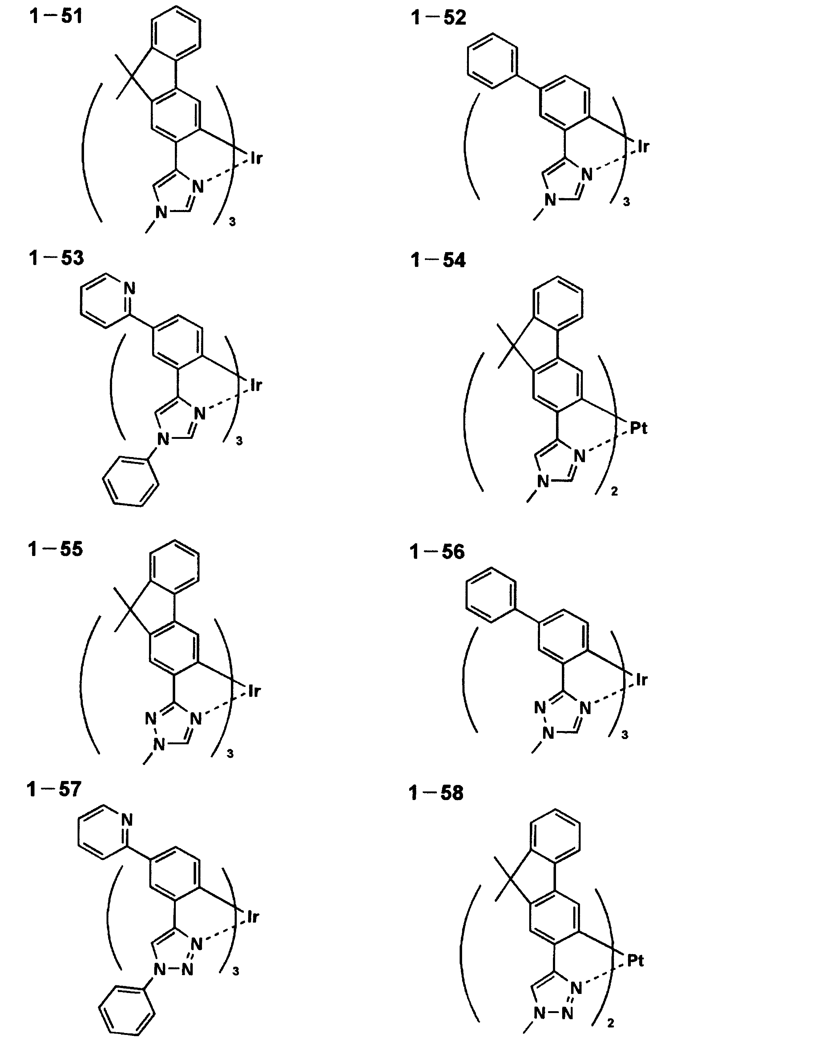


リン光発光性化合物を含有する発光層が一般式(2)で表される化合物を含有することが好ましい。


さらにより好ましくは、一般式(2)で表される化合物は、分子内に少なくとも1つの窒素原子を含む6員芳香族複素環、又は、縮合環を構成する環の1つとして少なくとも1つの窒素原子を含む6員芳香族複素環、を有する縮合環を有する。


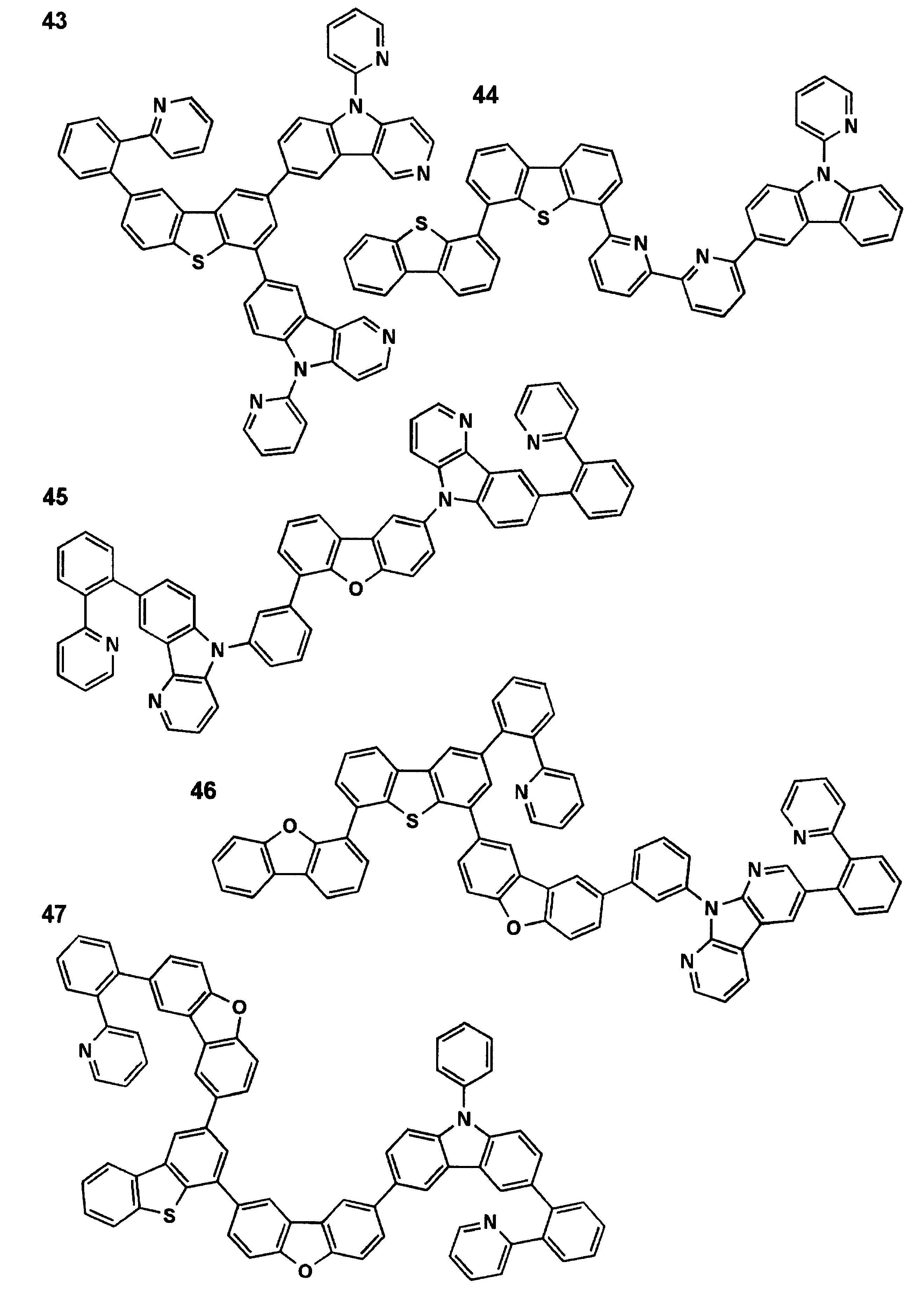


構造は1H-NMRスペクトル及び質量分析スペクトルによって確認した。
本発明の有機EL素子の構成層について説明する。本発明において、有機EL素子の層構成の好ましい具体例を以下に示すが、本発明はこれらに限定されない。
(ii)陽極/正孔輸送層/発光層/電子輸送層/陰極
(iii)陽極/正孔輸送層/発光層/正孔阻止層/電子輸送層/陰極
(iv)陽極/正孔輸送層/発光層/正孔阻止層/電子輸送層/陰極バッファー層/陰極
(v)陽極/正孔注入層/正孔輸送層/発光層/正孔阻止層/電子輸送層/陰極バッファー層/陰極
(vi)陽極/正孔注入層/正孔輸送層/発光層/正孔阻止層/電子輸送層/陰極バッファー層/陰極
(vii)陽極/正孔注入層/正孔輸送層/発光層/電子輸送層/陰極バッファー層/陰極
発光層は、ユニットを形成して発光層ユニットにすることもある。
本発明に係る発光層は、電極又は電子輸送層、正孔輸送層から注入されてくる電子及び正孔が再結合して発光する層であり、発光する部分は発光層の層内及び発光層と隣接層との界面である。
発光ドーパント(ドーパントともいう)について説明する。
本発明に係るリン光発光性化合物について説明する。
蛍光ドーパントとしては、クマリン系色素、ピラン系色素、シアニン系色素、クロコニウム系色素、スクアリウム系色素、オキソベンツアントラセン系色素、フルオレセイン系色素、ローダミン系色素、ピリリウム系色素、ペリレン系色素、スチルベン系色素、ポリチオフェン系色素、又は希土類錯体系蛍光体等や、レーザー色素に代表される蛍光量子収率が高い化合物が挙げられる。
本発明においてホスト化合物は、発光層に含有される化合物の内で、その層中での質量比が20%以上であり、且つ室温(25℃)においてリン光発光のリン光量子収率が、0.1未満の化合物と定義される。好ましくはリン光量子収率が0.01未満である。また、発光層に含有される化合物の中で、その層中での質量比が20%以上であることが好ましい。
正孔輸送層とは正孔を輸送する機能を有する正孔輸送材料からなり、広い意味で正孔注入層、電子阻止層も正孔輸送層に含まれる。正孔輸送層は単層又は複数層設けることができる。


阻止層は、上記の如く有機化合物薄膜の基本構成層の他に必要に応じて設けられるものである。例えば、特開平11-204258号公報、同11-204359号公報、及び「有機EL素子とその工業化最前線(1998年11月30日エヌ・ティー・エス社発行)」の237頁等に記載されている正孔阻止(ホールブロック)層がある。
注入層は必要に応じて設け、電子注入層と正孔注入層があり、上記の如く陽極と発光層又は正孔輸送層の間、及び陰極と発光層又は電子輸送層との間に存在させてもよい。
電子輸送層とは電子を輸送する機能を有する材料からなり、広い意味で電子注入層、正孔阻止層も電子輸送層に含まれる。電子輸送層は単層若しくは複数層を設けることができる。


有機EL素子における陽極としては、仕事関数の大きい(4eV以上)金属、合金、電気伝導性化合物及びこれらの混合物を電極物質とするものが好ましく用いられる。このような電極物質の具体例としては、Au等の金属、CuI、インジウムチンオキシド(ITO)、SnO2、ZnO等の導電性透明材料が挙げられる。
一方、陰極としては仕事関数の小さい(4eV以下)金属(電子注入性金属と称する)、合金、電気伝導性化合物及びこれらの混合物を電極物質とするものが用いられる。このような電極物質の具体例としては、ナトリウム、ナトリウム-カリウム合金、マグネシウム、リチウム、マグネシウム/銅混合物、マグネシウム/銀混合物、マグネシウム/アルミニウム混合物、マグネシウム/インジウム混合物、アルミニウム/酸化アルミニウム(Al2O3)混合物、インジウム、リチウム/アルミニウム混合物、希土類金属等が挙げられる。
本発明の有機EL素子に用いることのできる支持基板(以下、基板ともいう)としては、ガラス、プラスチック等の種類には特に限定はなく、また透明であっても不透明であってもよい。支持基板側から光を取り出す場合には、支持基板は透明であることが好ましい。好ましく用いられる透明な支持基板としては、ガラス、石英、透明樹脂フィルムを挙げることができる。特に好ましい支持基板は、有機EL素子にフレキシブル性を与えることが可能な樹脂フィルムである。
有機EL素子の製造方法の一例として、陽極/正孔注入層/正孔輸送層/発光層/正孔阻止層/電子輸送層/陰極バッファー層(電子注入層)/陰極からなる素子の製造方法について説明する。
本発明に用いられる封止手段としては、例えば、封止部材と電極、支持基板とを接着剤で接着する方法を挙げることができる。
有機層を挟み支持基板と対向する側の前記封止膜、あるいは前記封止用フィルムの外側に、素子の機械的強度を高めるために保護膜、あるいは保護板を設けてもよい。特に封止が前記封止膜により行われている場合には、その機械的強度は必ずしも高くないため、このような保護膜、保護板を設けることが好ましい。これに使用することができる材料としては、前記封止に用いたのと同様なガラス板、ポリマー板・フィルム、金属板・フィルム等を用いることができるが、軽量且つ薄膜化ということからポリマーフィルムを用いることが好ましい。
有機EL素子は空気よりも屈折率の高い(屈折率が1.7~2.1程度)層の内部で発光し、発光層で発生した光のうち15%から20%程度の光しか取り出せないことが一般的に言われている。これは、臨界角以上の角度θで界面(透明基板と空気との界面)に入射する光は、全反射を起こし素子外部に取り出すことができないことや、透明電極ないし発光層と透明基板との間で光が全反射を起こし、光が透明電極ないし発光層を導波し、結果として光が素子側面方向に逃げるためである。
本発明の有機EL素子は基板の光取り出し側に、例えば、マイクロレンズアレイ状の構造を設けるように加工したり、あるいはいわゆる集光シートと組み合わせることにより、特定方向、例えば、素子発光面に対し正面方向に集光することにより、特定方向上の輝度を高めることができる。
本発明の有機EL素子は、表示デバイス、ディスプレイ、各種発光光源として用いることができる。発光光源として、例えば、照明装置(家庭用照明、車内照明)、時計や液晶用バックライト、看板広告、信号機、光記憶媒体の光源、電子写真複写機の光源、光通信処理機の光源、光センサーの光源等が挙げられるがこれに限定するものではないが、特に液晶表示装置のバックライト、照明用光源としての用途に有効に用いることができる。
本発明の有機EL素子や該素子に係る化合物の発光色は、「新編色彩科学ハンドブック」(日本色彩学会編、東京大学出版会、1985)の108頁の図4.16において、分光放射輝度計CS-1000(コニカミノルタセンシング社製)で測定した結果を、CIE色度座標に当てはめたときの色で決定される。
本発明の表示装置について説明する。本発明の表示装置は、本発明の有機EL素子を具備したものである。
本発明の照明装置について説明する。本発明の照明装置は、本発明の有機EL素子を有する。
本発明の有機EL素子を具備した、本発明の照明装置の一態様について説明する。


〈有機EL素子1-1の作製〉
陽極として100mm×100mm×1.1mmのガラス基板上にITO(インジウムチンオキシド)を100nm製膜した基板(NHテクノグラス社製NA45)にパターニングを行った後、このITO透明電極を設けた透明支持基板をイソプロピルアルコールで超音波洗浄し、乾燥窒素ガスで乾燥し、UVオゾン洗浄を5分間行った。
有機EL素子1-1において、正孔輸送層(HTL)の正孔輸送材料1、発光層(EML)のホスト化合物(例示化合物1)、発光層(EML)の青色発光ドーパントDPT、電子輸送層(ETL)の電子輸送材料1、及び各層の膜厚のみを表1記載のように変えた以外は、有機EL素子1-1と同様にして有機EL素子1-2~1-8を作製した。
得られた有機EL素子1-1~1-8を評価するに際しては、作製後の各有機EL素子の非発光面をガラスカバーで覆い、ガラスカバーと有機EL素子が作製されたガラス基板とが接触するガラスカバー側の周囲にシール剤としてエポキシ系光硬化型接着剤(東亞合成社製ラクストラックLC0629B)を適用し、これを上記陰極側に重ねて前記透明支持基板と密着させ、ガラス基板側からUV光を照射して硬化させ、封止して、上記の図5、図6に示すような照明装置を形成して評価した。次いで、下記評価を行った。
有機EL素子を室温下、2.5mA/cm2の定電流条件下による連続発光を行い、初期輝度の半分の輝度になるのに要する時間(τ1/2)を測定し、この値を発光寿命の尺度とした。なお、発光寿命は有機EL素子1-1を100と設定する相対値で表した。有機EL素子の発光輝度の測定はCS-1000(コニカミノルタセンシング社製)を用いた。
色度変動幅は、分光放射輝度計CS-1000(コニカミノルタセンシング社製)を用い、正面輝度300cd/m2~1500cd/m2におけるCIE1931、x、y値の変動最大距離ΔEを下式で求め、結果をA~Dに分類した。
A:ΔEが0.01未満
B:ΔEが0.01以上0.015未満
C:ΔEが0.015以上0.02未満
D:ΔEが0.02以上
以上の評価結果を表1に示した。なお、以下の表中、下記の略号を用いた。
HIL:正孔注入層
EML:発光層
EML1:発光層1
EML2:発光層2
ETL:電子輸送層
ホスト:ホスト化合物
ΔPL/ΔEL:発光層寄与率
寿命:発光寿命
ドーパント:リン光発光性化合物(リン光ドーパント)又は蛍光ドーパント

有機EL素子1-3の作製において、発光層(EML)のホスト化合物である例示化合物1の代わりにホスト化合物として一般式(2)で表される例示化合物97を用い、発光層(EML)の青色リン光発光ドーパント1-81の代わりに青色リン光発光ドーパント化合物Aを用いた以外は同様にして、有機EL素子2-1を作製した。
有機EL素子2-1において、正孔輸送材料、ホスト化合物、青色発光ドーパントを表2記載の化合物に変えて、有機EL素子2-1と同様にして有機EL素子2-2~2-3を作製した。
陽極として100mm×100mm×1.1mmのガラス基板上にITO(インジウムチンオキシド)を100nm製膜した基板(NHテクノグラス社製NA-45)にパターニングを行った後、このITO透明電極を設けた透明支持基板をイソプロピルアルコールで超音波洗浄し、乾燥窒素ガスで乾燥し、UVオゾン洗浄を5分間行った。
得られた有機EL素子2-1~2-4を評価するに際しては、作製後の各有機EL素子の非発光面をガラスカバーで覆い、ガラスカバーと有機EL素子が作製されたガラス基板とが接触するガラスカバー側の周囲にシール剤としてエポキシ系光硬化型接着剤(東亞合成社製ラクストラックLC0629B)を適用し、これを上記陰極側に重ねて前記透明支持基板と密着させ、ガラス基板側からUV光を照射して硬化させ、封止して、上記の図5、図6に示すような照明装置を形成して評価した。次いで、下記評価を行った。
前記した様に、石英基板上に発光層のみを50nmの膜厚で設けた後、室温(23℃)にてスポット光源・ライトニングキュアLC8(浜松ホトニクス製)にて(365nm)の光を照射距離1cm、20min.照射し、照射前後でのPLスペクトル測定(分光放射輝度計CS-1000(コニカミノルタセンシング社製)を使用)から得られる発光極大の強度比を下記式より算出した。耐UV光劣化比=PL(照射後)/PL(照射後)。

《有機EL素子3-1の作製》
有機EL素子2-1の作製において、発光層(EML)のホスト化合物である例示化合物97の代わりにホスト化合物として例示化合物1を用いた以外は同様にして、有機EL素子3-1を作製した。
有機EL素子3-1の作製において、表3記載のように、化合物Aから一般式(1)で表されるリン光発光性化合物に変えた以外は、有機EL素子3-1と同様にして有機EL素子3-2~3-4を作製した。
得られた有機EL素子3-1~3-3を評価するに際しては、作製後の各有機EL素子の非発光面をガラスカバーで覆い、ガラスカバーと有機EL素子が作製されたガラス基板とが接触するガラスカバー側の周囲にシール剤としてエポキシ系光硬化型接着剤(東亞合成社製ラクストラックLC0629B)を適用し、これを上記陰極側に重ねて前記透明支持基板と密着させ、ガラス基板側からUV光を照射して硬化させ、封止して、上記の図5、図6に示すような照明装置を形成して評価した。次いで、下記評価を行った。
◎:ダークスポットの発生が全くない
○:ダークスポット1個以上、5個未満
△:ダークスポット5個以上、20個未満
×:ダークスポット20個以上
以上の結果を表3に示した。

有機EL素子2-1の作製において、正孔輸送層(HTL)の正孔輸送材料1の代わりに正孔輸送材料5を用いた以外は同様にして、有機EL素子4-1を作製した。
有機EL素子4-1の作製において、正孔注入層、正孔輸送層、発光ドーパントを表4記載の化合物に変えた以外は、有機EL素子4-1と同様にして有機EL素子4-2~4-3を作製した。
得られた有機EL素子4-1~4-3を評価するに際しては、作製後の各有機EL素子の非発光面をガラスカバーで覆い、ガラスカバーと有機EL素子が作製されたガラス基板とが接触するガラスカバー側の周囲にシール剤としてエポキシ系光硬化型接着剤(東亞合成社製ラクストラックLC0629B)を適用し、これを上記陰極側に重ねて前記透明支持基板と密着させ、ガラス基板側からUV光を照射して硬化させ、封止して、上記の図5、図6に示すような照明装置を形成して評価した。次いで、下記評価を行った。

有機EL素子2-1の作製において、発光層中のホスト化合物97に代えてホスト化合物100を用いた以外は同様にして、有機EL素子5-1を作製した。
有機EL素子5-1において、正孔輸送材料、リン光青色発光ドーパントを表5記載の化合物に変えた以外は、有機EL素子5-1と同様にして有機EL素子5-2~5-9を作製した。
得られた有機EL素子5-1~5-9を評価するに際しては、作製後の各有機EL素子の非発光面をガラスカバーで覆い、ガラスカバーと有機EL素子が作製されたガラス基板とが接触するガラスカバー側の周囲にシール剤としてエポキシ系光硬化型接着剤(東亞合成社製ラクストラックLC0629B)を適用し、これを上記陰極側に重ねて前記透明支持基板と密着させ、ガラス基板側からUV光を照射して硬化させ、封止して、上記の図5、図6に示すような照明装置を形成して評価した。次いで、下記評価を行った。

有機EL素子2-1の作製において、ホスト化合物97の代わりにCBP、を用いた以外は同様にして、有機EL素子6-1を作製した。
有機EL素子6-1の作製において、正孔輸送層の正孔輸送材料、発光層のホスト化合物、発光ドーパントを表6記載の化合物に変えた以外は、有機EL素子6-1と同様にして有機EL素子6-2~6-8を作製した。
得られた有機EL素子6-1~6-8を評価するに際しては、作製後の各有機EL素子の非発光面をガラスカバーで覆い、ガラスカバーと有機EL素子が作製されたガラス基板とが接触するガラスカバー側の周囲にシール剤としてエポキシ系光硬化型接着剤(東亞合成社製ラクストラックLC0629B)を適用し、これを上記陰極側に重ねて前記透明支持基板と密着させ、ガラス基板側からUV光を照射して硬化させ、封止して、上記の図5、図6に示すような照明装置を形成して評価した。次いで、下記評価を行った。

〈有機EL素子7-1の作製〉
有機EL素子2-1の作製において、正孔輸送材料1の代わりに1-90、発光ドーパント化合物Aの代わりに発光ドーパント1-86、ホスト化合物97の代わりにホスト化合物1を用い、発光層の膜厚を120nmとした以外は同様にして、有機EL素子7-1を作製した。
有機EL素子7-1の作製において、更に別のモリブデン製抵抗加熱ボートにホスト化合物98を200mg入れ、有機EL素子7-1と同様に真空蒸着装置に取付けた。
有機EL素子7-2において、発光層の構成、膜厚を表7記載の化合物に変えた以外は、有機EL素子7-2と同様にして有機EL素子7-3を作製した。
得られた有機EL素子7-1~7-3を評価するに際しては、作製後の各有機EL素子の比発光面をガラスカバーで覆い、ガラスカバーと有機EL素子が作製されたガラス基板とが接触するガラスカバー側の周囲にシール剤としてエポキシ系光硬化型接着剤(東亞合成社製ラクストラックLC0629B)を適用し、これを上記陰極側に重ねて前記透明支持基板と密着させ、ガラス基板側からUV光を照射して硬化させ、封止して、上記の図5、図6に示すような照明装置を形成して評価した。次いで、下記評価を行った。

〈有機ELフルカラー表示装置の作製〉
図7は有機ELフルカラー表示装置の概略構成図である。陽極としてガラス基板201上にITO透明電極(202)を100nm成膜した基板(NHテクノグラス社製NA45)に100μmのピッチでパターニングを行った後、このガラス基板上でITO透明電極の間に非感光性ポリイミドの隔壁203(幅20μm、厚さ2.0μm)をフォトリソグラフィーで形成させた。
正孔輸送材料1-87 20質量部
シクロヘキシルベンゼン 50質量部
イソプロピルビフェニル 50質量部
(青色発光層組成物)
一般式(2)-1 0.7質量部
一般式(1)1-86 0.04質量部
シクロヘキシルベンゼン 50質量部
イソプロピルビフェニル 50質量部
(緑色発光層組成物)
一般式(2)-1 0.7質量部
Ir(ppy)3 0.04質量部
シクロヘキシルベンゼン 50質量部
イソプロピルビフェニル 50質量部
(赤色発光層組成物)
一般式(2)-1 0.7質量部
Ir(piq)3 0.04質量部
シクロヘキシルベンゼン 50質量部
イソプロピルビフェニル 50質量部
3 画素
5 走査線
6 データ線
7 電源ライン
10 有機EL素子
11 スイッチングトランジスタ
12 駆動トランジスタ
13 コンデンサ
A 表示部
B 制御部
101 有機EL素子
102 ガラスカバー
105 陰極
106 有機EL層
107 透明電極付きガラス基板
108 窒素ガス
109 捕水剤
201 ガラス基板
202 ITO透明電極
203 隔壁
204 正孔注入層
205B、205G、205R 発光層
206 Al
Claims (15)
- 陽極と陰極の間に、少なくとも1層の発光層が挟持された有機エレクトロルミネッセンス素子であって、エレクトロルミネッセンスの強度減衰率に対するフォトルミネッセンスの強度減衰率の比ΔPL/ΔELで定義される発光層寄与率が、0.3以上1.0以下であることを特徴とする有機エレクトロルミネッセンス素子。
- 前記発光層に少なくとも一種のリン光発光性化合物を含有することを特徴とする請求項1に記載の有機エレクトロルミネッセンス素子。
- 前記発光層の単膜における耐UV光劣化比の値が、0.6以上であることを特徴とする請求項1又は2に記載の有機エレクトロルミネッセンス素子。
- 前記陽極と前記発光層の間に正孔輸送層が発光層に隣接して挟持され、かつ前記発光層に含有される前記少なくとも一種のリン光発光性化合物のイオン化ポテンシャルが、前記正孔輸送層に含まれる少なくとも一種の正孔輸送材料のイオン化ポテンシャルに対して、-0.3~0.2eVの範囲内であることを特徴とする請求項2又は3に記載の有機エレクトロルミネッセンス素子。
- 前記陽極と前記正孔輸送層の間に正孔注入層が挟持され、かつ前記正孔注入層に含まれる少なくとも一種の正孔注入材料のイオン化ポテンシャルが、前記陽極の仕事関数に対して-0.2~0.3eVの範囲内であり、且つ、前記正孔輸送層に含まれる少なくとも1つの正孔輸送材料のイオン化ポテンシャルに対して-0.3~0.2eVの範囲内であることを特徴とする請求項4に記載の有機エレクトロルミネッセンス素子。
- 前記リン光発光性化合物の少なくとも一種は、発光極大波長が480nm以下であることを特徴とする請求項2~5のいずれか一項に記載の有機エレクトロルミネッセンス素子。
- 前記正孔輸送層に少なくとも一種の有機金属錯体を含有することを特徴とする請求項4~6のいずれか一項に記載の有機エレクトロルミネッセンス素子。
- 前記有機金属錯体が、一般式(1)で表されることを特徴とする請求項7に記載の有機エレクトロルミネッセンス素子。

- 前記発光層に含まれるリン光発光性化合物が前記一般式(1)で表されることを特徴とする請求項2~8のいずれか一項に記載の有機エレクトロルミネッセンス素子。
- 前記正孔輸送層に隣接する発光層に含有されるリン光発光性化合物と、該正孔輸送層に含まれる少なくとも一種の金属錯体が同一であることを特徴とする請求項7~9のいずれか一項に記載の有機エレクトロルミネッセンス素子。
- 前記リン光発光性化合物を含有する発光層が、一般式(2)で表される化合物を含有することを特徴とする請求項2~10のいずれか一項に記載の有機エレクトロルミネッセンス素子。


- 前記一般式(2)で表される化合物を含有した層が湿式法により成膜され、形成される工程を経て製造されたものであることを特徴とする請求項11に記載の有機エレクトロルミネッセンス素子。
- 白色に発光することを特徴とする請求項1~12のいずれか一項に記載の有機エレクトロルミネッセンス素子。
- 請求項1~13のいずれか一項に記載の有機エレクトロルミネッセンス素子を備えたことを特徴とする照明装置。
- 請求項1~13のいずれか一項に記載の有機エレクトロルミネッセンス素子を備えたことを特徴とする表示装置。
Priority Applications (2)
| Application Number | Priority Date | Filing Date | Title |
|---|---|---|---|
| JP2013520541A JP6094480B2 (ja) | 2011-06-15 | 2012-06-11 | 有機エレクトロルミネッセンス素子、照明装置、表示装置及び有機エレクトロルミネッセンス素子の製造方法 |
| US14/119,533 US9040975B2 (en) | 2011-06-15 | 2012-06-11 | Organic electroluminescence element, illumination device, and display device |
Applications Claiming Priority (2)
| Application Number | Priority Date | Filing Date | Title |
|---|---|---|---|
| JP2011133044 | 2011-06-15 | ||
| JP2011-133044 | 2011-06-15 |
Publications (1)
| Publication Number | Publication Date |
|---|---|
| WO2012173079A1 true WO2012173079A1 (ja) | 2012-12-20 |
Family
ID=47357066
Family Applications (1)
| Application Number | Title | Priority Date | Filing Date |
|---|---|---|---|
| PCT/JP2012/064884 WO2012173079A1 (ja) | 2011-06-15 | 2012-06-11 | 有機エレクトロルミネッセンス素子、照明装置及び表示装置 |
Country Status (3)
| Country | Link |
|---|---|
| US (1) | US9040975B2 (ja) |
| JP (1) | JP6094480B2 (ja) |
| WO (1) | WO2012173079A1 (ja) |
Cited By (8)
| Publication number | Priority date | Publication date | Assignee | Title |
|---|---|---|---|---|
| WO2014088300A1 (en) * | 2012-12-04 | 2014-06-12 | Rohm And Haas Electronic Materials Korea Ltd. | Organic electroluminescence compounds and organic electroluminescence device comprising the same |
| KR101561338B1 (ko) | 2013-06-13 | 2015-10-16 | 주식회사 두산 | 유기 화합물 및 이를 포함하는 유기 전계 발광 소자 |
| US9673401B2 (en) | 2013-06-28 | 2017-06-06 | Universal Display Corporation | Organic electroluminescent materials and devices |
| JP2017519809A (ja) * | 2014-04-11 | 2017-07-20 | メルク パテント ゲーエムベーハー | 有機エレクトロルミネッセンス素子のための材料 |
| WO2017134748A1 (ja) * | 2016-02-02 | 2017-08-10 | パイオニア株式会社 | 発光装置 |
| JP2020068308A (ja) * | 2018-10-25 | 2020-04-30 | 住友化学株式会社 | 発光素子 |
| WO2020084923A1 (ja) | 2018-10-25 | 2020-04-30 | 住友化学株式会社 | 発光素子 |
| JP2020102654A (ja) * | 2020-04-06 | 2020-07-02 | パイオニア株式会社 | 発光装置 |
Families Citing this family (2)
| Publication number | Priority date | Publication date | Assignee | Title |
|---|---|---|---|---|
| CN104045595A (zh) * | 2014-06-25 | 2014-09-17 | 北京绿人科技有限责任公司 | 一种有机化合物及其使用该有机化合物的电致发光器件 |
| US11167375B2 (en) | 2018-08-10 | 2021-11-09 | The Research Foundation For The State University Of New York | Additive manufacturing processes and additively manufactured products |
Citations (9)
| Publication number | Priority date | Publication date | Assignee | Title |
|---|---|---|---|---|
| JPH05326149A (ja) * | 1992-05-20 | 1993-12-10 | Fukuvi Chem Ind Co Ltd | 分散型エレクトロルミネッセンス |
| JP2004006066A (ja) * | 2002-04-15 | 2004-01-08 | Sony Corp | 有機電界発光素子及び発光装置 |
| JP2004311424A (ja) * | 2003-03-26 | 2004-11-04 | Konica Minolta Holdings Inc | 有機エレクトロルミネッセンス素子、照明装置および表示装置 |
| JP2004335438A (ja) * | 2003-04-30 | 2004-11-25 | Korea Inst Of Science & Technology | ナノ複合体を発光層として用いる高分子エレクトロルミネセンス素子 |
| WO2005122702A2 (ja) * | 2004-06-16 | 2005-12-29 | Sharp Kk | 有機エレクトロルミネセンス素子、その検査装置及び検査方法 |
| JP2009108053A (ja) * | 2007-10-11 | 2009-05-21 | Japan Science & Technology Agency | シロール化合物とその製造方法およびそれを用いた有機電界発光素子 |
| JP2011084531A (ja) * | 2009-10-19 | 2011-04-28 | Konica Minolta Holdings Inc | 有機エレクトロルミネッセンス素子用材料、有機エレクトロルミネッセンス素子、照明装置及び表示装置 |
| JP2011109120A (ja) * | 2011-01-06 | 2011-06-02 | Konica Minolta Holdings Inc | 有機エレクトロルミネッセンス素子、表示装置及び照明装置 |
| WO2011065137A1 (ja) * | 2009-11-27 | 2011-06-03 | シャープ株式会社 | 有機エレクトロルミネッセンス素子、およびその製造方法、ならびに有機エレクトロルミネッセンス表示装置 |
Family Cites Families (16)
| Publication number | Priority date | Publication date | Assignee | Title |
|---|---|---|---|---|
| JP3366401B2 (ja) | 1992-11-20 | 2003-01-14 | 出光興産株式会社 | 白色有機エレクトロルミネッセンス素子 |
| US6097147A (en) | 1998-09-14 | 2000-08-01 | The Trustees Of Princeton University | Structure for high efficiency electroluminescent device |
| TWI265750B (en) | 2003-02-27 | 2006-11-01 | Toyota Jidoshokki Kk | Organic electro-luminescence devices |
| JP2004235168A (ja) | 2004-05-20 | 2004-08-19 | Toyota Industries Corp | 有機エレクトロルミネッセンス素子 |
| KR20070084413A (ko) * | 2004-12-08 | 2007-08-24 | 후지 덴키 홀딩스 가부시키가이샤 | 유기el소자 |
| KR101359630B1 (ko) * | 2006-10-23 | 2014-02-10 | 삼성디스플레이 주식회사 | 유기 전계 발광 화합물 및 이를 이용한 유기 전계 발광소자 |
| JP2008147400A (ja) | 2006-12-08 | 2008-06-26 | Idemitsu Kosan Co Ltd | 有機エレクトロルミネッセンス素子 |
| JP2008147398A (ja) | 2006-12-08 | 2008-06-26 | Idemitsu Kosan Co Ltd | 有機エレクトロルミネッセンス素子 |
| JP2008147399A (ja) | 2006-12-08 | 2008-06-26 | Idemitsu Kosan Co Ltd | 有機エレクトロルミネッセンス素子 |
| US8795855B2 (en) * | 2007-01-30 | 2014-08-05 | Global Oled Technology Llc | OLEDs having high efficiency and excellent lifetime |
| US7745990B2 (en) * | 2007-03-29 | 2010-06-29 | Konica Minolta Holdings, Inc. | White light emitting organic electroluminescent element and lighting device |
| KR101557498B1 (ko) * | 2008-11-05 | 2015-10-07 | 삼성전자주식회사 | 양자점 발광소자 및 그 제조방법 |
| JP5493333B2 (ja) * | 2008-11-05 | 2014-05-14 | コニカミノルタ株式会社 | 有機エレクトロルミネッセンス素子、白色有機エレクトロルミネッセンス素子、表示装置及び照明装置 |
| JP5707665B2 (ja) * | 2008-12-03 | 2015-04-30 | コニカミノルタ株式会社 | 有機エレクトロルミネッセンス素子、該素子を備えた照明装置及び表示装置 |
| JP5127814B2 (ja) * | 2008-12-19 | 2013-01-23 | キヤノン株式会社 | 有機発光素子及びそれを利用した発光装置、表示装置 |
| JP5697856B2 (ja) * | 2009-06-24 | 2015-04-08 | コニカミノルタ株式会社 | 有機エレクトロルミネッセンス素子、白色有機エレクトロルミネッセンス素子、表示装置及び照明装置 |
-
2012
- 2012-06-11 JP JP2013520541A patent/JP6094480B2/ja active Active
- 2012-06-11 WO PCT/JP2012/064884 patent/WO2012173079A1/ja active Application Filing
- 2012-06-11 US US14/119,533 patent/US9040975B2/en active Active
Patent Citations (9)
| Publication number | Priority date | Publication date | Assignee | Title |
|---|---|---|---|---|
| JPH05326149A (ja) * | 1992-05-20 | 1993-12-10 | Fukuvi Chem Ind Co Ltd | 分散型エレクトロルミネッセンス |
| JP2004006066A (ja) * | 2002-04-15 | 2004-01-08 | Sony Corp | 有機電界発光素子及び発光装置 |
| JP2004311424A (ja) * | 2003-03-26 | 2004-11-04 | Konica Minolta Holdings Inc | 有機エレクトロルミネッセンス素子、照明装置および表示装置 |
| JP2004335438A (ja) * | 2003-04-30 | 2004-11-25 | Korea Inst Of Science & Technology | ナノ複合体を発光層として用いる高分子エレクトロルミネセンス素子 |
| WO2005122702A2 (ja) * | 2004-06-16 | 2005-12-29 | Sharp Kk | 有機エレクトロルミネセンス素子、その検査装置及び検査方法 |
| JP2009108053A (ja) * | 2007-10-11 | 2009-05-21 | Japan Science & Technology Agency | シロール化合物とその製造方法およびそれを用いた有機電界発光素子 |
| JP2011084531A (ja) * | 2009-10-19 | 2011-04-28 | Konica Minolta Holdings Inc | 有機エレクトロルミネッセンス素子用材料、有機エレクトロルミネッセンス素子、照明装置及び表示装置 |
| WO2011065137A1 (ja) * | 2009-11-27 | 2011-06-03 | シャープ株式会社 | 有機エレクトロルミネッセンス素子、およびその製造方法、ならびに有機エレクトロルミネッセンス表示装置 |
| JP2011109120A (ja) * | 2011-01-06 | 2011-06-02 | Konica Minolta Holdings Inc | 有機エレクトロルミネッセンス素子、表示装置及び照明装置 |
Cited By (14)
| Publication number | Priority date | Publication date | Assignee | Title |
|---|---|---|---|---|
| WO2014088300A1 (en) * | 2012-12-04 | 2014-06-12 | Rohm And Haas Electronic Materials Korea Ltd. | Organic electroluminescence compounds and organic electroluminescence device comprising the same |
| KR101561338B1 (ko) | 2013-06-13 | 2015-10-16 | 주식회사 두산 | 유기 화합물 및 이를 포함하는 유기 전계 발광 소자 |
| US9673401B2 (en) | 2013-06-28 | 2017-06-06 | Universal Display Corporation | Organic electroluminescent materials and devices |
| US10418564B2 (en) | 2014-04-11 | 2019-09-17 | Merck Patent Gmbh | Materials for organic electroluminescent devices |
| JP2017519809A (ja) * | 2014-04-11 | 2017-07-20 | メルク パテント ゲーエムベーハー | 有機エレクトロルミネッセンス素子のための材料 |
| WO2017134748A1 (ja) * | 2016-02-02 | 2017-08-10 | パイオニア株式会社 | 発光装置 |
| JPWO2017134748A1 (ja) * | 2016-02-02 | 2018-11-22 | パイオニア株式会社 | 発光装置 |
| JP2020068308A (ja) * | 2018-10-25 | 2020-04-30 | 住友化学株式会社 | 発光素子 |
| WO2020084923A1 (ja) | 2018-10-25 | 2020-04-30 | 住友化学株式会社 | 発光素子 |
| WO2020084924A1 (ja) | 2018-10-25 | 2020-04-30 | 住友化学株式会社 | 発光素子 |
| JP2020068307A (ja) * | 2018-10-25 | 2020-04-30 | 住友化学株式会社 | 発光素子 |
| KR20210084503A (ko) | 2018-10-25 | 2021-07-07 | 스미또모 가가꾸 가부시키가이샤 | 발광 소자 |
| KR20210084504A (ko) | 2018-10-25 | 2021-07-07 | 스미또모 가가꾸 가부시키가이샤 | 발광 소자 |
| JP2020102654A (ja) * | 2020-04-06 | 2020-07-02 | パイオニア株式会社 | 発光装置 |
Also Published As
| Publication number | Publication date |
|---|---|
| US20140091299A1 (en) | 2014-04-03 |
| JP6094480B2 (ja) | 2017-03-15 |
| JPWO2012173079A1 (ja) | 2015-02-23 |
| US9040975B2 (en) | 2015-05-26 |
Similar Documents
| Publication | Publication Date | Title |
|---|---|---|
| JP5765223B2 (ja) | 有機エレクトロルミネッセンス素子の製造方法、並びに有機エレクトロルミネッセンス素子を備えた照明装置及び表示装置 | |
| JP5839027B2 (ja) | 有機エレクトロルミネッセンス素子、その製造方法、照明装置及び表示装置 | |
| JP5533652B2 (ja) | 白色発光有機エレクトロルミネッセンス素子、照明装置及び表示装置 | |
| JP5707665B2 (ja) | 有機エレクトロルミネッセンス素子、該素子を備えた照明装置及び表示装置 | |
| JP5659478B2 (ja) | 有機エレクトロルミネッセンス素子、照明装置及び表示装置 | |
| JP5870782B2 (ja) | 有機エレクトロルミネッセンス素子、有機エレクトロルミネッセンス素子の製造方法、照明装置及び表示装置 | |
| JP5853964B2 (ja) | 有機エレクトロルミネッセンス素子、照明装置及び表示装置 | |
| WO2010090077A1 (ja) | 有機エレクトロルミネッセンス素子、該素子を備えた照明装置及び表示装置 | |
| WO2011004639A1 (ja) | 有機エレクトロルミネッセンス素子、新規な化合物、照明装置及び表示装置 | |
| WO2009107497A1 (ja) | 有機エレクトロルミネッセンス素子材料、有機エレクトロルミネッセンス素子、有機エレクトロルミネッセンス素子の製造方法、照明装置及び表示装置 | |
| JP6094480B2 (ja) | 有機エレクトロルミネッセンス素子、照明装置、表示装置及び有機エレクトロルミネッセンス素子の製造方法 | |
| JP6056884B2 (ja) | 有機エレクトロルミネッセンス素子の製造方法 | |
| JP2010114180A (ja) | 有機エレクトロルミネッセンス素子、白色有機エレクトロルミネッセンス素子、表示装置及び照明装置 | |
| JP5569531B2 (ja) | 有機エレクトロルミネッセンス素子、有機エレクトロルミネッセンス素子材料、表示装置及び照明装置 | |
| JP5652083B2 (ja) | 有機エレクトロルミネッセンス素子、表示装置及び照明装置 | |
| JP2013168552A (ja) | 有機エレクトロルミネッセンス素子、それが具備された表示装置及び照明装置 | |
| JP5423363B2 (ja) | 有機エレクトロルミネッセンス素子、表示装置及び照明装置 | |
| JP5218185B2 (ja) | 有機エレクトロルミネッセンス素子、それを用いた表示装置及び照明装置 | |
| JP6011535B2 (ja) | 有機エレクトロルミネッセンス素子、照明装置、表示装置及び有機エレクトロルミネッセンス素子の製造方法 | |
| WO2013031662A1 (ja) | 有機エレクトロルミネッセンス素子、照明装置及び表示装置 | |
| JP5320881B2 (ja) | 有機エレクトロルミネッセンス素子、表示装置、照明装置及び有機エレクトロルミネッセンス素子材料 | |
| JP5338578B2 (ja) | 有機エレクトロルミネッセンス素子、表示装置及び照明装置 | |
| JP2016048796A (ja) | 有機エレクトロルミネッセンス素子、それが具備された表示装置及び照明装置 |
Legal Events
| Date | Code | Title | Description |
|---|---|---|---|
| 121 | Ep: the epo has been informed by wipo that ep was designated in this application |
Ref document number: 12801201 Country of ref document: EP Kind code of ref document: A1 |
|
| ENP | Entry into the national phase |
Ref document number: 2013520541 Country of ref document: JP Kind code of ref document: A |
|
| WWE | Wipo information: entry into national phase |
Ref document number: 14119533 Country of ref document: US |
|
| NENP | Non-entry into the national phase |
Ref country code: DE |
|
| 122 | Ep: pct application non-entry in european phase |
Ref document number: 12801201 Country of ref document: EP Kind code of ref document: A1 |