WO2012169599A1 - 樹脂成形装置および樹脂成形方法 - Google Patents
樹脂成形装置および樹脂成形方法 Download PDFInfo
- Publication number
- WO2012169599A1 WO2012169599A1 PCT/JP2012/064713 JP2012064713W WO2012169599A1 WO 2012169599 A1 WO2012169599 A1 WO 2012169599A1 JP 2012064713 W JP2012064713 W JP 2012064713W WO 2012169599 A1 WO2012169599 A1 WO 2012169599A1
- Authority
- WO
- WIPO (PCT)
- Prior art keywords
- resin
- molding
- vibration
- transfer surface
- molding die
- Prior art date
- Legal status (The legal status is an assumption and is not a legal conclusion. Google has not performed a legal analysis and makes no representation as to the accuracy of the status listed.)
- Ceased
Links
Images






Classifications
-
- B—PERFORMING OPERATIONS; TRANSPORTING
- B29—WORKING OF PLASTICS; WORKING OF SUBSTANCES IN A PLASTIC STATE IN GENERAL
- B29C—SHAPING OR JOINING OF PLASTICS; SHAPING OF MATERIAL IN A PLASTIC STATE, NOT OTHERWISE PROVIDED FOR; AFTER-TREATMENT OF THE SHAPED PRODUCTS, e.g. REPAIRING
- B29C37/00—Component parts, details, accessories or auxiliary operations, not covered by group B29C33/00 or B29C35/00
- B29C37/0003—Discharging moulded articles from the mould
-
- B—PERFORMING OPERATIONS; TRANSPORTING
- B29—WORKING OF PLASTICS; WORKING OF SUBSTANCES IN A PLASTIC STATE IN GENERAL
- B29C—SHAPING OR JOINING OF PLASTICS; SHAPING OF MATERIAL IN A PLASTIC STATE, NOT OTHERWISE PROVIDED FOR; AFTER-TREATMENT OF THE SHAPED PRODUCTS, e.g. REPAIRING
- B29C33/00—Moulds or cores; Details thereof or accessories therefor
- B29C33/44—Moulds or cores; Details thereof or accessories therefor with means for, or specially constructed to facilitate, the removal of articles, e.g. of undercut articles
-
- B—PERFORMING OPERATIONS; TRANSPORTING
- B29—WORKING OF PLASTICS; WORKING OF SUBSTANCES IN A PLASTIC STATE IN GENERAL
- B29C—SHAPING OR JOINING OF PLASTICS; SHAPING OF MATERIAL IN A PLASTIC STATE, NOT OTHERWISE PROVIDED FOR; AFTER-TREATMENT OF THE SHAPED PRODUCTS, e.g. REPAIRING
- B29C43/00—Compression moulding, i.e. applying external pressure to flow the moulding material; Apparatus therefor
- B29C43/02—Compression moulding, i.e. applying external pressure to flow the moulding material; Apparatus therefor of articles of definite length, i.e. discrete articles
- B29C43/021—Compression moulding, i.e. applying external pressure to flow the moulding material; Apparatus therefor of articles of definite length, i.e. discrete articles characterised by the shape of the surface
-
- B—PERFORMING OPERATIONS; TRANSPORTING
- B29—WORKING OF PLASTICS; WORKING OF SUBSTANCES IN A PLASTIC STATE IN GENERAL
- B29C—SHAPING OR JOINING OF PLASTICS; SHAPING OF MATERIAL IN A PLASTIC STATE, NOT OTHERWISE PROVIDED FOR; AFTER-TREATMENT OF THE SHAPED PRODUCTS, e.g. REPAIRING
- B29C43/00—Compression moulding, i.e. applying external pressure to flow the moulding material; Apparatus therefor
- B29C43/32—Component parts, details or accessories; Auxiliary operations
- B29C43/50—Removing moulded articles
-
- B—PERFORMING OPERATIONS; TRANSPORTING
- B29—WORKING OF PLASTICS; WORKING OF SUBSTANCES IN A PLASTIC STATE IN GENERAL
- B29C—SHAPING OR JOINING OF PLASTICS; SHAPING OF MATERIAL IN A PLASTIC STATE, NOT OTHERWISE PROVIDED FOR; AFTER-TREATMENT OF THE SHAPED PRODUCTS, e.g. REPAIRING
- B29C45/00—Injection moulding, i.e. forcing the required volume of moulding material through a nozzle into a closed mould; Apparatus therefor
- B29C45/17—Component parts, details or accessories; Auxiliary operations
- B29C45/46—Means for plasticising or homogenising the moulding material or forcing it into the mould
- B29C45/56—Means for plasticising or homogenising the moulding material or forcing it into the mould using mould parts movable during or after injection, e.g. injection-compression moulding
- B29C45/568—Applying vibrations to the mould parts
-
- B—PERFORMING OPERATIONS; TRANSPORTING
- B29—WORKING OF PLASTICS; WORKING OF SUBSTANCES IN A PLASTIC STATE IN GENERAL
- B29D—PRODUCING PARTICULAR ARTICLES FROM PLASTICS OR FROM SUBSTANCES IN A PLASTIC STATE
- B29D11/00—Producing optical elements, e.g. lenses or prisms
- B29D11/00009—Production of simple or compound lenses
- B29D11/00038—Production of contact lenses
- B29D11/00125—Auxiliary operations, e.g. removing oxygen from the mould, conveying moulds from a storage to the production line in an inert atmosphere
- B29D11/00192—Demoulding, e.g. separating lenses from mould halves
-
- B—PERFORMING OPERATIONS; TRANSPORTING
- B29—WORKING OF PLASTICS; WORKING OF SUBSTANCES IN A PLASTIC STATE IN GENERAL
- B29D—PRODUCING PARTICULAR ARTICLES FROM PLASTICS OR FROM SUBSTANCES IN A PLASTIC STATE
- B29D11/00—Producing optical elements, e.g. lenses or prisms
- B29D11/00009—Production of simple or compound lenses
- B29D11/00432—Auxiliary operations, e.g. machines for filling the moulds
-
- B—PERFORMING OPERATIONS; TRANSPORTING
- B29—WORKING OF PLASTICS; WORKING OF SUBSTANCES IN A PLASTIC STATE IN GENERAL
- B29C—SHAPING OR JOINING OF PLASTICS; SHAPING OF MATERIAL IN A PLASTIC STATE, NOT OTHERWISE PROVIDED FOR; AFTER-TREATMENT OF THE SHAPED PRODUCTS, e.g. REPAIRING
- B29C43/00—Compression moulding, i.e. applying external pressure to flow the moulding material; Apparatus therefor
- B29C43/32—Component parts, details or accessories; Auxiliary operations
- B29C43/50—Removing moulded articles
- B29C2043/5092—Removing moulded articles using vibrations means
-
- B—PERFORMING OPERATIONS; TRANSPORTING
- B29—WORKING OF PLASTICS; WORKING OF SUBSTANCES IN A PLASTIC STATE IN GENERAL
- B29L—INDEXING SCHEME ASSOCIATED WITH SUBCLASS B29C, RELATING TO PARTICULAR ARTICLES
- B29L2011/00—Optical elements, e.g. lenses, prisms
- B29L2011/0016—Lenses
Definitions
- the present invention relates to a resin molding apparatus and a resin molding method, and more particularly to a lens molding apparatus and a lens molding method capable of easily and accurately molding a lens having a complicated shape.
- a lens molding method has been used in which a lens having a transfer surface for transferring a lens shape is pressed against a resin material and the resin material is cured in this state to mold the lens.
- the lens molding method when the resin material is cured and then released from the lens, the lens may be damaged by the adhesive force between the lens and the transfer surface.
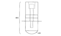
- Patent Document 1 in a compound lens molding apparatus, a high frequency voltage is applied to the molding die 400 to vibrate the molding surface 401 of the molding die 400, thereby forming the molding.
- a technique for releasing the obtained lens is disclosed. In this method, it is said that the adhesive strength of the lens with the molding surface 401 can be lowered by elastically deforming the molding surface 401, so that the mold can be safely released.
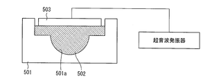
- Patent Document 2 discloses a method for releasing a resin molded product using ultrasonic waves.
- a resin such as an epoxy resin having an adhesive effect is injected into a molding die 501 that is a casting mold having an open air and has a cavity 501a, and the resin is heated and cured.
- the molded product 502 is molded.
- a flat plate-like vibrator 503 is arranged so as to be in direct contact with the upper surface of the molded product 502 after molding. Vibration is directly transmitted from the vibrator 503 to the molded product 502, and the molded product 502 can be easily peeled off from the molding die 501.
- Patent Document 3 discloses a technique similar to the technique disclosed in Patent Document 2.
- the present invention has been made to solve the above problems, and an object thereof is to realize a resin molding apparatus and a resin molding method capable of easily molding a resin molded product with high accuracy.
- a resin molding apparatus includes a first molding die having a first transfer surface for transferring a predetermined shape to a resin material, and a predetermined molding to the resin material.
- a second molding die having a second transfer surface for transferring the shape, the second transfer surface facing the first transfer surface; the first molding die; and
- a moving means for changing the relative position of the second molding die and the resin material supplied between the first transfer surface and the second transfer surface are cured to mold a resin molding.
- a resin molding apparatus including a curing unit, and applying a vibration from a side surface of the first molding die, thereby forming a gap in at least a part between the first transfer surface and the resin molded product. It is characterized by comprising first vibration applying means to be formed.
- a resin molded product is molded.
- the vibration is applied from the side surface of the first molding die by the first vibration applying means after the resin material is cured and before the first transfer surface is separated from the resin molding by the moving means.
- a gap is formed in at least a portion between the first transfer surface and the resin molded product. This gap serves as a starting point from which the resin molded product is separated from the first transfer surface.
- vibration is applied from the side surface of the first molding die, only a part of the first molding die vibrates.
- the resin molding apparatus includes a substrate, a molding die having a transfer surface for transferring a predetermined shape to the resin material, and a moving unit that changes a relative position between the substrate and the molding die.
- a resin molding apparatus comprising a curing means for molding a resin molding by curing the resin material supplied between the substrate and the transfer surface, and applying vibration from a side surface of the molding die
- the first vibration applying means for forming a gap in at least a part between the transfer surface and the resin molded product is provided.
- the resin molding is molded by curing the resin material supplied between the substrate and the transfer surface of the molding die by the curing means.
- the transfer surface is transferred by applying vibration from the side surface of the molding die by the first vibration applying unit.
- a gap is formed in at least a part between the resin molded product and the resin molded product. This gap serves as a starting point where the resin molded product and the transfer surface are separated. Further, since vibration is applied from the side surface of the molding die, only a part of the molding die vibrates.
- the resin material supplied between the first transfer surface of the first molding die and the second transfer surface of the second molding die is cured to form a resin molded product.
- a resin molding method comprising: a resin material curing step for molding the mold; a mold release step for separating the first transfer surface from the resin molding; and a step for taking out the resin molding from the second molding die. Then, by applying vibration from the side surface of the first molding die between the resin material curing step and the mold release step, at least between the first transfer surface and the resin molded product. It has the 1st vibration provision process which forms a space
- the resin material curing step the resin material supplied between the first transfer surface of the first molding die and the second transfer surface of the second molding die is cured.
- the resin molded product is molded by curing with.
- a gap is formed in at least a part between the first transfer surface and the resin molded product. Is formed.
- This void serves as a starting point at which the resin molded product and the first transfer surface are separated in the mold release step. Further, since vibration is applied from the side surface of the first molding die, only a part of the first molding die vibrates.
- the resin molding method according to the present invention includes a resin material curing step in which a resin material supplied between a substrate and a transfer surface of a molding die is cured to form a resin molded product, and the transfer surface is used as the resin molded product.
- the resin material is molded by curing the resin material supplied between the substrate and the transfer surface of the molding die by the curing means.
- a gap is formed in at least a part between the transfer surface and the resin molded product. This void serves as a starting point for separating the resin molded product and the transfer surface in the mold release step.
- vibration is applied from the side surface of the molding die, only a part of the molding die vibrates.
- the resin molding method according to the present invention includes a resin material curing step of molding a resin molding by curing a resin material supplied between a substrate and a transfer surface of a molding die, and the substrate from the resin molding.
- a resin molding method having a mold release step of separating and a step of taking out the resin molded product from the molding die, wherein vibration is generated from a side surface of the substrate between the resin material curing step and the mold release step.
- the resin material is molded by curing the resin material supplied between the substrate and the transfer surface of the molding die by the curing means.
- a gap is formed in at least a part between the substrate and the resin molded product.
- This void serves as a starting point from which the resin molded product is separated from the substrate in the mold release step.
- vibration is applied from the side surface of the substrate, only a part of the substrate vibrates. In this way, since vibration is indirectly applied to the resin molded product, a load on the resin molded product at the time of applying vibration can be reduced. Therefore, the resin molded product and the substrate can be easily separated. Therefore, it is possible to realize a resin molding method capable of easily molding a resin molded product with high accuracy.
- the resin molding apparatus transfers the predetermined shape to the first molding die having the first transfer surface for transferring the predetermined shape to the resin material, and the resin material.
- a second molding die having a second transfer surface for facing the first transfer surface, the first molding die, and the second molding
- a moving means for changing a relative position to the mold; and a curing means for curing the resin material supplied between the first transfer surface and the second transfer surface to mold a resin molded product.
- a resin molding apparatus comprising: a first forming a void in at least a part between the first transfer surface and the resin molded product by applying vibration from a side surface of the first molding die. It is the structure provided with the vibration provision means.
- the resin molding method according to the present invention cures the resin material supplied between the first transfer surface of the first molding die and the second transfer surface of the second molding die, and resin Resin molding having a resin material curing step for molding a molded product, a mold releasing step for separating the first transfer surface from the resin molded product, and a taking-out step for taking out the resin molded product from the second molding die
- a vibration is applied from a side surface of the first molding die between the resin material curing step and the mold releasing step, so that the first transfer surface and the resin molded product are separated from each other. It is the structure which has a 1st vibration provision process which forms a space
- FIGS. 1 to 10 An embodiment of the present invention will be described with reference to FIGS. 1 to 10 as follows.
- FIG. 1 is a diagram illustrating a configuration of a lens molding apparatus (resin molding apparatus) 100 according to the present embodiment.
- the lens molding device 100 is a device that molds a lens from a resin material, and includes a molding die 1, a molding die 2, a support device 3, a heating device 4, an ultrasonic transducer 5, and a resonance device 6.
- the molding die 1 corresponds to the first molding die described in the claims, and is supported by the support device 3.
- the molding die 2 corresponds to the second molding die described in the claims, and is provided on the heating device 4.
- the support device 3 includes an extendable arm 3a, and can move the molding die 1 up and down in the drawing.
- the support device 3 corresponds to the moving means described in the claims.
- the molding die 1 has a transfer surface 1a for transferring a predetermined lens shape to a resin material, and an aspherical recess is formed at the center of the transfer surface 1a.
- the molding die 2 also has a transfer surface 2a for transferring a predetermined lens shape to the resin material, and an aspherical recess is formed at the center of the transfer surface 2a.
- the transfer surface 1a and the transfer surface 2a face each other.
- the heating device 4 corresponds to the curing means described in the claims, and the resin material supplied between the transfer surface 1a and the transfer surface 2a is cured by heating the molding die 2. .
- the start / end of heating may be controlled by a sequence program or the like, or may be controlled manually.
- the ultrasonic vibrator 5 corresponds to the first vibration applying means and the second vibration applying means described in the claims, and generates ultrasonic vibrations in response to a signal given from the resonance device 6. To do.
- the ultrasonic transducer 5 can be attached to the side surface 1 b of the molding die 1 and the side surface 2 b of the molding die 2.
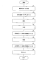
- FIG. 2 is a flowchart showing the procedure of the molding process of the lens according to this embodiment.
- step S1 the resin material 7 is supplied between the transfer surface 1a of the molding die 1 and the transfer surface 2a of the molding die 2.
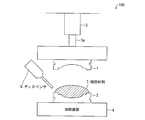
- the resin material 7 is injected on the transfer surface 2 a of the molding die 2 using the dispenser 8.
- the resin material 7 is a thermosetting resin that is cured by being heated.
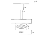
- step S2 the transfer surface 1a of the molding die 1 is pressed against the resin material 7 (step S2).
- step S3 the resin material curing step.
- step S4 heating is stopped and the resin material 7 is cooled. Thereby, the lens 17 is molded.
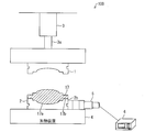
- the ultrasonic vibrator 5 is attached to the side surface 1 b of the molding die 1, and a signal is output from the resonance device 6 to vibrate the ultrasonic vibrator 5.
- the ultrasonic transducer 5 applies ultrasonic vibration of, for example, 27 kHz from the side surface 1b, and the molding die 1 vibrates in the radial direction of the lens 17 (shear direction, surface direction of the transfer surface 1a) (step).
- S5 first vibration applying step). Due to this vibration, the molding die 1 is locally elastically deformed in the shearing direction, and a local deviation occurs between the transfer surface 1 a and the lens 17.
- the adhesive force between the transfer surface 1a of the molding die 1 and the lens 17 is reduced, and at least a part of the surface of the lens 17 is slightly peeled off from the transfer surface 1a.
- a gap is formed in at least a part of the gap.
- the transfer surface 1a of the molding die 1 is separated from the lens 17 (step S6, mold release step).
- step S6 mold release step.
- the gap expands over the entire boundary between the transfer surface 1a and the lens 17 at the time of mold release. Therefore, the molding die 1 can be easily released from the lens 17 without applying a load to the lens 17.
- the ultrasonic vibrator 5 is attached to the side surface 2 b of the molding die 2, and the ultrasonic vibrator 5 is vibrated by outputting a signal from the resonance device 6.
- the ultrasonic transducer 5 applies ultrasonic vibration of 27 kHz, for example, from the side surface 2b, and the molding die 2 vibrates in the radial direction of the lens 17 (shear direction, surface direction of the transfer surface 2a) (step).
- S7, second vibration applying step Due to this vibration, the molding die 2 is locally elastically deformed in the shearing direction, and a local deviation occurs between the transfer surface 2 a and the lens 17.
- a vacuum gap is formed between the lens 17 and the transfer surface 2a.
- the adhesive force between the transfer surface 2a of the molding die 2 and the lens 17 is reduced, and at least a part of the surface of the lens 17 is slightly peeled off from the transfer surface 2a.
- a gap is formed in at least a part of the gap.
- the lens 17 is taken out from the molding die 2 (step S8, taking out step).
- step S8 taking out step.
- the gap spreads over the entire boundary between the transfer surface 2 a and the lens 17 when taken out. Therefore, the lens 17 can be easily taken out from the molding die 2 without applying a load to the lens 17.
- the transfer surface 1a is obtained by applying vibration in the radial direction of the lens 17 to the molding dies 1 and 2 before step S6 (release process) and before step S8 (removal process).
- a local gap is generated between 2a and the lens 17. Since this gap is the starting point for separating the lens 17 and the transfer surfaces 1a and 2a, the lens 17 and the transfer surfaces 1a and 2a can be easily separated.
- the molding die 1 was first separated from the lens, and then the lens was taken out from the molding die 2.
- the present invention is not limited thereto, and the molding die 2 is first separated from the lens. Thereafter, the lens may be taken out from the molding die 1. That is, the first vibration applying step and the second vibration applying step may be reversed. In this way, by applying ultrasonic vibration to the molding die in contact with the lens surface opposite to the lens surface that is in contact with the molding die where the lens is to be left after the mold release step, the lens extraction position can be adjusted. Can be controlled.
- FIG. 9 (Reduction effect of mold release force) (A) of FIG. 9 is a table showing the relationship between the pressing force indicating the initial pressure at the time of releasing (the force pressing the transfer surface against the resin material) and the releasing force indicating the force required for releasing
- FIG. 9B is a graph showing the relationship.
- the release force in the method of the present embodiment in which 27 kHz ultrasonic vibration is applied to the mold before release is indicated by a solid line
- the release force in the normal method in which no ultrasonic vibration is applied Is indicated by a broken line.
- the release force could be reduced by about 70% by applying ultrasonic vibration before release.
- step S5 as shown in FIG. 5, a gap is formed in at least a part between the non-optical surface 17b of the lens 17 and the transfer surface 1a in contact with the non-optical surface 17b, and the optical surface 17a of the lens 17 is formed. It is preferable not to form between the transfer surface 1a and the transfer surface 1a.
- step S7 as shown in FIG. 7, an air gap is formed in at least a part between the non-optical surface 17b of the lens 17 and the transfer surface 1a in contact with the non-optical surface 17b. It is preferable not to form between 17a and the transfer surface 1a.
- the optical surface means a surface that participates in the light spot formation of the lens 17
- the non-optical surface means a surface that does not participate in the light spot formation of the lens 17.
- the non-optical surface is formed on the outer peripheral side of the optical surface, and is composed of, for example, a flat flange portion.
- the lens molding apparatus 100 can mold a lens having a complicated shape with high accuracy and ease. Further, a lens with a large margin of resin material, large thickness deviation, and large aspheric amount can be easily molded.
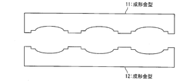
- the molds 1 and 2 used for lens molding are molds for molding one lens, but a plurality of arrays such as the molds 11 and 12 shown in FIG. You may use the metal mold
- the ultrasonic vibration includes a component in the direction perpendicular to the transfer surface, but the component in the lens radial direction (surface direction of the transfer surface) is dominant. Therefore, a shear release force is mainly generated between the lens and the transfer surface.
- the ultrasonic vibration is a single vibration in the radial direction of the lens, the amplitude of the ultrasonic vibration is A, and the frequency of the ultrasonic vibration is f, the displacement amount z with respect to the transfer surface of the lens is
- the ultrasonic vibration velocity v and the ultrasonic vibration acceleration a are respectively
- F is the maximum force acting in the direction of the transfer surface.
- M is the lens mass
- S is the lens area
- h is the lens thickness
- ⁇ is the lens density.
- the vibration applied to the molding die or the substrate before the mold release step and the removal step is preferably an ultrasonic vibration of 20 to 60 kHz.
- FIG. 11 is a diagram illustrating a configuration of a lens molding device 200 according to a modification of the present embodiment.
- the lens molding apparatus 200 has a configuration in which the molding die 2 is replaced with a substrate 9 in the lens molding apparatus 100 shown in FIG.
- the substrate 9 is provided on the heating device 4, and the ultrasonic vibrator 5 can be attached to the side surface 9 a of the substrate 9.
- the lens molding process in the lens molding apparatus 200 is substantially the same as that in the lens molding apparatus 100. That is, a resin material is supplied between the substrate 9 and the transfer surface 1a of the molding die 1, and in a state where the transfer surface 1a is pressed against the resin material, the resin material is heated and cured to form a lens. Subsequently, by applying ultrasonic vibration from the side surface 1b of the molding die 1 by the ultrasonic vibrator 5, a gap is formed in at least a part between the transfer surface 1a and the lens (molding die vibration applying step). Then, the transfer surface 1a is pulled away from the lens.
- a gap is formed in at least a part between the substrate 9 and the lens (substrate vibration applying step), and then the lens. Is removed from the substrate 9.
- the lens, the transfer surface 1a, and the substrate are imparted to the molding die 1 and the substrate 9 by applying vibration in the radial direction of the lens. 9 and a local void is generated. Since this gap is the starting point for separating the lens from the transfer surface 1a and the substrate 9, the lens, the transfer surface 1a and the substrate 9 can be easily separated from each other.
- the molding die vibration applying process and the substrate vibration applying process may be reversed. That is, after the resin material is cured to form a lens, first, ultrasonic vibration is applied from the side surface 9a of the substrate 9 by the ultrasonic vibrator 5, thereby at least a part between the substrate 9 and the lens. After that, the molding die 1 is raised and the substrate 9 is pulled away from the lens. As a result, the lens is attached to the transfer surface 1 a of the molding die 1. Subsequently, at least a portion between the transfer surface 1a and the lens is provided by applying ultrasonic vibration from the side surface 1b of the molding die 1 by the ultrasonic vibrator 5 while supporting the side surface of the lens by a support member or the like. After that, a gap is formed, and the lens is taken out from the transfer surface 1a.
- the ultrasonic vibration is applied to the molding die or the substrate.
- the vibration applied to the molding die or the substrate is not limited to the ultrasonic vibration.
- sonic vibration of less than 20 kHz may be used.
- ultrasonic vibration is applied to two molding dies, or the molding die and the substrate by one ultrasonic vibrator.
- Ultrasonic vibration may be applied to the molding die or the molding die and the substrate.
- the first and second vibration applying means described in the claims may be the same member or separate members.
- the ultrasonic transducer may be movable by a slide mechanism.
- the resin molding apparatus by applying vibration from the side surface of the second molding die, at least between the second transfer surface and the resin molded product. It is preferable to include second vibration applying means for forming a gap in a part.
- vibration is applied from the side surface of the second molding die by the second vibration applying means until the resin molding is taken out from the second molding die.
- a gap is formed in at least a part between the second transfer surface and the resin molded product.
- This gap is a starting point from which the resin molded product and the second transfer surface are separated.
- vibration is applied from the side surface of the second molding die, only a part of the second molding die vibrates.
- vibration is indirectly applied to the resin molded product, a load on the resin molded product at the time of applying vibration can be reduced as compared with the conventional configuration in which the entire transfer surface of the molding die is vibrated. Therefore, the resin molding can be easily taken out from the second molding die.
- a second vibration applying unit that forms a gap in at least a part between the substrate and the resin molded product by applying vibration from a side surface of the substrate. It is preferable to provide.
- a void is formed at least in part.
- This void serves as a starting point from which the resin molded product and the substrate are separated.
- vibration is applied from the side surface of the substrate, only a part of the substrate vibrates.
- vibration is indirectly applied to the resin molded product, a load on the resin molded product at the time of applying vibration can be reduced as compared with the conventional configuration in which the entire transfer surface of the molding die is vibrated. Therefore, the resin molded product can be easily taken out from the substrate.
- the first vibration applying unit and the second vibration applying unit are the same member.
- the vibration is preferably ultrasonic vibration.
- the frequency of vibration applied to the molding die or the substrate is larger, the speed of the resin molded product after the mold release with respect to the force in the surface direction of the transfer surface or the substrate when applying the vibration can be suppressed. Therefore, the load on the resin molded product can be suppressed by setting the vibration to ultrasonic vibration.
- the resin molding is preferably one or a plurality of lenses.
- the embodiment of the present invention is particularly suitable for molding a lens having a complicated shape since it can be released without applying a load to the resin material.
- the number of members constituting the resin molding apparatus can be reduced.
- the lens includes an optical surface and a non-optical surface formed on the outer peripheral side of the optical surface, and the gap includes the non-optical surface and the non-optical surface.
- the gap is formed at least in part between the surface in contact with the surface and not between the optical surface and the surface in contact with the optical surface.
- the void is formed only on the non-optical surface of the resin molded product, it is possible to further reduce the load on the optical surface at the time of releasing or taking out. Therefore, the influence on the performance of the resin molded product can be minimized.
- the second transfer surface and the It is preferable to have the 2nd vibration provision process which forms a space
- At least one part between a 2nd transfer surface and a resin molding is provided by giving a vibration from the side surface of a 2nd shaping
- a void is formed in the surface. This void serves as a starting point at which the resin molded product and the second transfer surface are separated in the extraction step.
- vibration is applied from the side surface of the second molding die, only a part of the second molding die vibrates.
- vibration is indirectly applied to the resin molded product, a load on the resin molded product at the time of applying vibration can be reduced as compared with the conventional configuration in which the entire transfer surface of the molding die is vibrated. Therefore, the resin molding can be easily taken out from the second molding die.
- vibration is applied from a side surface of the substrate between the mold release step and the take-out step, thereby at least one between the substrate and the resin molded product. It is preferable to have a substrate vibration applying step of forming a void in the part.
- a gap is formed in at least a part between the substrate and the resin molding by applying vibration from the side surface of the substrate between the mold release step and the take-out step.
- This void serves as a starting point at which the resin molded product and the substrate are separated in the extraction step. Further, since vibration is applied from the side surface of the substrate, only a part of the substrate vibrates. In this way, since vibration is indirectly applied to the resin molded product, a load on the resin molded product at the time of applying vibration can be reduced. Therefore, the resin molded product can be easily taken out from the substrate.
- a vibration is applied from a side surface of the molding die between the mold release step and the take-out step, whereby the transfer surface and the resin molded product are interposed. It is preferable to have a molding die vibration imparting step of forming a void in at least a part of the mold.
- gap is formed in at least one part between a transfer surface and a resin molding by providing a vibration from the side surface of a shaping die between a mold release process and a taking-out process.
- This void serves as a starting point at which the resin molded product and the transfer surface are separated in the take-out process.
- vibration is applied from the side surface of the molding die, only a part of the molding die vibrates.
- vibration is indirectly applied to the resin molded product, a load on the resin molded product at the time of applying vibration can be reduced as compared with the conventional configuration in which the entire transfer surface of the molding die is vibrated. Therefore, the resin molded product can be easily taken out from the molded substrate.
- the vibration is preferably ultrasonic vibration.
- the frequency of vibration applied to the molding die or the substrate is larger, the speed of the resin molded product after the mold release with respect to the force in the surface direction of the transfer surface or the substrate when applying the vibration can be suppressed. Therefore, the load on the resin molded product can be suppressed by setting the vibration to ultrasonic vibration.
- the resin molding is preferably one or a plurality of lenses.
- the present invention is particularly suitable for molding a lens having a complicated shape since it can be released without applying a load to the resin material.
- the lens includes an optical surface and a non-optical surface formed on the outer peripheral side of the optical surface, and the gap includes the non-optical surface and the non-optical surface.
- the gap is formed at least in part between the surface in contact with the surface and not between the optical surface and the surface in contact with the optical surface.
- the void is formed only on the non-optical surface of the resin molded product, it is possible to further reduce the load on the optical surface in the mold release step or the removal step. Therefore, the influence on the performance of the resin molded product can be minimized.
- the present invention can be applied not only to a lens molding apparatus but also to an apparatus for molding any resin molding other than a lens.
Landscapes
- Engineering & Computer Science (AREA)
- Mechanical Engineering (AREA)
- Manufacturing & Machinery (AREA)
- Health & Medical Sciences (AREA)
- Ophthalmology & Optometry (AREA)
- Moulds For Moulding Plastics Or The Like (AREA)
- Casting Or Compression Moulding Of Plastics Or The Like (AREA)
- Injection Moulding Of Plastics Or The Like (AREA)
Abstract
本発明に係るレンズ成形装置(100)は、樹脂材料に所定のレンズ形状を転写するための転写面(1a)を有する成形金型(1)と、樹脂材料に所定のレンズ形状を転写するための転写面(2a)を有する成形金型(2)と、成形金型(1)を移動させる支持装置(3)と、転写面(1a)と転写面(2a)との間に供給された樹脂材料を硬化させてレンズを成形する加熱装置(4)と、成形金型(1・2)の側面から振動を付与することにより、転写面(1a・2a)とレンズとの間の少なくとも一部に空隙を形成する超音波振動子(5)とを備える。
Description
本発明は、樹脂成形装置および樹脂成形方法に関し、特に、複雑な形状を有するレンズを高精度かつ容易に成形可能なレンズ成形装置およびレンズ成形方法に関する。
従来より、レンズ形状を転写するための転写面を有する金型を樹脂材料に押し当て、その状態で樹脂材料を硬化させることにより、レンズを成形するレンズ成形方法が用いられている。当該レンズ成形方法では、樹脂材料を硬化させた後、レンズから離型させるときに、レンズと転写面との間の付着力により、レンズが損傷してしまうおそれがある。
これに対し、特許文献1には、図12に示すように、複合レンズの成形装置において、高周波の電圧を成形金型400に印加して成形金型400の成形面401を振動させて、成形したレンズを離型する技術が開示されている。この方法では、成形面401を弾性変形させることにより、レンズの成形面401との密着強度を下げることができるので、安全に離型することができるとされている。
また、特許文献2には、超音波による樹脂成形物の離型方法が開示されている。同文献では、図13に示すように、キャビティ501aを有する大気開放の注形型である成形金型501に、接着効果のあるエポキシ樹脂等の樹脂が注入され、当該樹脂が加熱されて硬化することにより、成形物502が成形される。成形後の成形物502の上面に直接接触するように平板形状の振動子503が配接される。振動子503から成形物502に直接振動が伝達され、成形金型501から成形物502を容易に剥すことができる。
また、特許文献3にも、特許文献2に開示の技術と同様の技術が開示されている。
光学系の高性能化に伴い、複雑な形状を有する薄肉のレンズを高精度に加工する技術が重要となっている。特に、薄肉であって偏肉性および非球面量が大きいレンズは、十分な剛性を確保することができないため、成形型に付着したレンズを剥す際の負荷により、レンズ自体に変形や割れなどの損傷を生じるおそれがある。そのため、非球面レンズ等の成形では、成形物と成形金型との抵抗を極力少なくすることが要求され、離型が難しいという問題がある。
これに対し、特許文献1~3に開示の技術では、振動子を成形物に直接接触させているため、成形物の全体に振動が与えられる。そのため、成形物が薄肉のレンズである場合、レンズに損傷を与えやすい。
本発明は、上記の問題点を解決するためになされたもので、その目的は、樹脂成形物を高精度かつ容易に成形可能な樹脂成形装置および樹脂成形方法を実現することにある。
上記の課題を解決するために、本発明に係る樹脂成形装置は、樹脂材料に所定の形状を転写するための第1の転写面を有する第1の成形金型と、前記樹脂材料に所定の形状を転写するための第2の転写面を有し、当該第2の転写面が前記第1の転写面と対向している第2の成形金型と、前記第1の成形金型と前記第2の成形金型との相対位置を変化させる移動手段と、前記第1の転写面と前記第2の転写面との間に供給された前記樹脂材料を硬化させて樹脂成形物を成形する硬化手段とを備える樹脂成形装置であって、前記第1の成形金型の側面から振動を付与することにより、前記第1の転写面と前記樹脂成形物との間の少なくとも一部に空隙を形成する第1の振動付与手段を備えることを特徴としている。
上記の構成によれば、第1の成形金型の第1の転写面と第2の成形金型の第2の転写面との間に供給された樹脂材料を硬化手段によって硬化させることにより、樹脂成形物が成形される。ここで、樹脂材料が硬化してから、移動手段によって第1の転写面を樹脂成形物から引き離すまでの間に、第1の振動付与手段によって、第1の成形金型の側面から振動を付与することにより、第1の転写面と樹脂成形物との間の少なくとも一部に空隙が形成される。この空隙は、樹脂成形物と第1の転写面とが離れる起点となる。また、振動は第1の成形金型の側面から付与されるため、第1の成形金型の一部のみが振動する。このように、振動が樹脂成形物に間接的に付与されるので、成形金型の転写面全体を振動させる従来構成に比べ、振動付与時の樹脂成形物への負荷を低減させることができる。よって、樹脂成形物と第1の転写面とを容易に引き離すことができる。したがって、樹脂成形物を高精度かつ容易に成形可能な樹脂成形装置を実現することができる。
本発明に係る樹脂成形装置は、基板と、樹脂材料に所定の形状を転写するための転写面を有する成形金型と、前記基板と前記成形金型との相対位置を変化させる移動手段と、前記基板と前記転写面との間に供給された前記樹脂材料を硬化させて樹脂成形物を成形する硬化手段とを備える樹脂成形装置であって、前記成形金型の側面から振動を付与することにより、前記転写面と前記樹脂成形物との間の少なくとも一部に空隙を形成する第1の振動付与手段を備えることを特徴としている。
上記の構成によれば、基板と成形金型の転写面との間に供給された樹脂材料を硬化手段によって硬化させることにより、樹脂成形物が成形される。ここで、樹脂材料が硬化してから、移動手段によって転写面を樹脂成形物から引き離すまでの間に、第1の振動付与手段によって、成形金型の側面から振動を付与することにより、転写面と樹脂成形物との間の少なくとも一部に空隙が形成される。この空隙は、樹脂成形物と転写面とが離れる起点となる。また、振動は成形金型の側面から付与されるため、成形金型の一部のみが振動する。このように、振動が樹脂成形物に間接的に付与されるので、成形金型の転写面全体を振動させる従来構成に比べ、振動付与時の樹脂成形物への負荷を低減させることができる。よって、樹脂成形物と転写面とを容易に引き離すことができる。したがって、樹脂成形物を高精度かつ容易に成形可能な樹脂成形装置を実現することができる。
本発明に係る樹脂成形方法は、第1の成形金型の第1の転写面と第2の成形金型の第2の転写面との間に供給された樹脂材料を硬化させて樹脂成形物を成形する樹脂材料硬化工程と、前記第1の転写面を前記樹脂成形物から引き離す離型工程と、前記樹脂成形物を前記第2の成形金型から取り出す取り出し工程とを有する樹脂成形方法であって、樹脂材料硬化工程と前記離型工程との間に、前記第1の成形金型の側面から振動を付与することにより、前記第1の転写面と前記樹脂成形物との間の少なくとも一部に空隙を形成する第1の振動付与工程を有することを特徴としている。
上記の構成によれば、樹脂材料硬化工程において、第1の成形金型の第1の転写面と第2の成形金型の第2の転写面との間に供給された樹脂材料を硬化手段によって硬化させることにより、樹脂成形物が成形される。ここで、樹脂材料硬化工程と離型工程との間に、第1の成形金型の側面から振動を付与することにより、第1の転写面と樹脂成形物との間の少なくとも一部に空隙が形成される。この空隙は、離型工程において、樹脂成形物と第1の転写面とが離れる起点となる。また、振動は第1の成形金型の側面から付与されるため、第1の成形金型の一部のみが振動する。このように、振動が樹脂成形物に間接的に付与されるので、成形金型の転写面全体を振動させる従来構成に比べ、振動付与時の樹脂成形物への負荷を低減させることができる。よって、樹脂成形物と第1の転写面とを容易に引き離すことができる。したがって、樹脂成形物を高精度かつ容易に成形可能な樹脂成形方法を実現することができる。
本発明に係る樹脂成形方法は、基板と成形金型の転写面との間に供給された樹脂材料を硬化させて樹脂成形物を成形する樹脂材料硬化工程と、前記転写面を前記樹脂成形物から引き離す離型工程と、前記樹脂成形物を前記基板から取り出す取り出し工程とを有する樹脂成形方法であって、前記樹脂材料硬化工程と前記離型工程との間に、前記成形金型の側面から振動を付与することにより、前記転写面と前記樹脂成形物との間の少なくとも一部に空隙を形成する成形金型振動付与工程を有することを特徴としている。
上記の構成によれば、樹脂材料硬化工程において、基板と成形金型の転写面との間に供給された樹脂材料を硬化手段によって硬化させることにより、樹脂成形物が成形される。ここで、樹脂材料硬化工程と離型工程との間に、成形金型の側面から振動を付与することにより、転写面と樹脂成形物との間の少なくとも一部に空隙が形成される。この空隙は、離型工程において、樹脂成形物と転写面とが離れる起点となる。また、振動は成形金型の側面から付与されるため、成形金型の一部のみが振動する。このように、振動が樹脂成形物に間接的に付与されるので、成形金型の転写面全体を振動させる従来構成に比べ、振動付与時の樹脂成形物への負荷を低減させることができる。よって、樹脂成形物と転写面とを容易に引き離すことができる。したがって、樹脂成形物を高精度かつ容易に成形可能な樹脂成形方法を実現することができる。
本発明に係る樹脂成形方法は、基板と成形金型の転写面との間に供給された樹脂材料を硬化させて樹脂成形物を成形する樹脂材料硬化工程と、前記基板を前記樹脂成形物から引き離す離型工程と、前記樹脂成形物を前記成形金型から取り出す取り出し工程とを有する樹脂成形方法であって、前記樹脂材料硬化工程と前記離型工程との間に、前記基板の側面から振動を付与することにより、前記基板と前記樹脂成形物との間の少なくとも一部に空隙を形成する基板振動付与工程を有することを特徴としている。
上記の構成によれば、樹脂材料硬化工程において、基板と成形金型の転写面との間に供給された樹脂材料を硬化手段によって硬化させることにより、樹脂成形物が成形される。ここで、樹脂材料硬化工程と離型工程との間に、基板の側面から振動を付与することにより、基板と樹脂成形物との間の少なくとも一部に空隙が形成される。この空隙は、離型工程において、樹脂成形物と基板とが離れる起点となる。また、振動は基板の側面から付与されるため、基板の一部のみが振動する。このように、振動が樹脂成形物に間接的に付与されるので、振動付与時の樹脂成形物への負荷を低減させることができる。よって、樹脂成形物と基板とを容易に引き離すことができる。したがって、樹脂成形物を高精度かつ容易に成形可能な樹脂成形方法を実現することができる。
以上のように、本発明に係る樹脂成形装置は、樹脂材料に所定の形状を転写するための第1の転写面を有する第1の成形金型と、前記樹脂材料に所定の形状を転写するための第2の転写面を有し、当該第2の転写面が前記第1の転写面と対向している第2の成形金型と、前記第1の成形金型と前記第2の成形金型との相対位置を変化させる移動手段と、前記第1の転写面と前記第2の転写面との間に供給された前記樹脂材料を硬化させて樹脂成形物を成形する硬化手段とを備える樹脂成形装置であって、前記第1の成形金型の側面から振動を付与することにより、前記第1の転写面と前記樹脂成形物との間の少なくとも一部に空隙を形成する第1の振動付与手段を備える構成である。また、本発明に係る樹脂成形方法は、第1の成形金型の第1の転写面と第2の成形金型の第2の転写面との間に供給された樹脂材料を硬化させて樹脂成形物を成形する樹脂材料硬化工程と、前記第1の転写面を前記樹脂成形物から引き離す離型工程と、前記樹脂成形物を前記第2の成形金型から取り出す取り出し工程とを有する樹脂成形方法であって、樹脂材料硬化工程と前記離型工程との間に、前記第1の成形金型の側面から振動を付与することにより、前記第1の転写面と前記樹脂成形物との間の少なくとも一部に空隙を形成する第1の振動付与工程を有する構成である。
したがって、樹脂成形物を高精度かつ容易に成形可能な樹脂成形装置および樹脂成形方法を実現できるという効果を奏する。
本発明の実施の一形態について、図1~図10に基づいて説明すれば以下のとおりである。
(レンズ成形装置の構成)
図1は、本実施形態に係るレンズ成形装置(樹脂成形装置)100の構成を示す図である。レンズ成形装置100は、樹脂材料からレンズを成形する装置であり、成形金型1、成形金型2、支持装置3、加熱装置4、超音波振動子5および共振装置6を備えている。
図1は、本実施形態に係るレンズ成形装置(樹脂成形装置)100の構成を示す図である。レンズ成形装置100は、樹脂材料からレンズを成形する装置であり、成形金型1、成形金型2、支持装置3、加熱装置4、超音波振動子5および共振装置6を備えている。
成形金型1は、特許請求の範囲に記載の第1の成形金型に相当するものであり、支持装置3によって支持されている。また、成形金型2は、特許請求の範囲に記載の第2の成形金型に相当するものであり、加熱装置4上に設けられている。支持装置3は、伸縮可能なアーム3aを備えており、成形金型1を図中上下に移動させることができる。なお、支持装置3は、特許請求の範囲に記載の移動手段に相当する。
成形金型1は、樹脂材料に所定のレンズ形状を転写するための転写面1aを有しており、転写面1aの中心部には、非球面形状の凹部が形成されている。同様に、成形金型2も、樹脂材料に所定のレンズ形状を転写するための転写面2aを有しており、転写面2aの中心部には、非球面形状の凹部が形成されている。転写面1aと転写面2aとは、互いに対向している。
加熱装置4は、特許請求の範囲に記載の硬化手段に相当するものであり、成形金型2を加熱することにより、転写面1aと転写面2aとの間に供給された樹脂材料を硬化させる。加熱の開始/終了は、シーケンスプログラム等によって制御してもよいし、手動で制御してもよい。
超音波振動子5は、特許請求の範囲に記載の第1の振動付与手段および第2の振動付与手段に相当するものであり、共振装置6から与えられる信号に応じて超音波の振動を発生する。超音波振動子5は、成形金型1の側面1bおよび成形金型2の側面2bに取り付け可能となっている。
(レンズの成形工程)
続いて、レンズ成形装置100におけるレンズの成形工程について、図2~図8を参照して説明する。
続いて、レンズ成形装置100におけるレンズの成形工程について、図2~図8を参照して説明する。
図2は、本実施形態に係るレンズの成形工程の手順を示すフローチャートである。
まず、ステップS1において、樹脂材料7を成形金型1の転写面1aと成形金型2の転写面2aとの間に供給する。例えば、図3に示すように、ディスペンサ8を用いて、樹脂材料7を成形金型2の転写面2a上の注入する。樹脂材料7は、加熱されることにより硬化する熱硬化性樹脂である。
続いて、図4に示すように、樹脂材料7に成形金型1の転写面1aを押し当てる(ステップS2)。この状態で、加熱装置4によって成形金型2を加熱する。これにより、樹脂材料7が硬化する(ステップS3、樹脂材料硬化工程)。
続いて、加熱を停止して、樹脂材料7を冷却する(ステップS4)。これにより、レンズ17が成形される。
続いて、図5に示すように、成形金型1の側面1bに超音波振動子5を取り付けて、共振装置6から信号を出力することにより、超音波振動子5を振動させる。これにより、超音波振動子5は、側面1bから例えば27kHzの超音波振動を付与し、成形金型1は、レンズ17の径方向(剪断方向、転写面1aの面方向)に振動する(ステップS5、第1の振動付与工程)。この振動により、成形金型1は剪断方向に局所的に弾性変形して、転写面1aとレンズ17との間では局所的にズレが生じる。これにより、成形金型1の転写面1aとレンズ17との間の付着力が低下するとともに、レンズ17の表面の少なくとも一部が転写面1aから僅かに剥離し、転写面1aとレンズ17との間の少なくとも一部に空隙が形成される。
続いて、図6に示すように、成形金型1の転写面1aをレンズ17から引き離す(ステップS6、離型工程)。上記のように、転写面1aとレンズ17との間の少なくとも一部に空隙が形成されているため、離型時に、この空隙が転写面1aとレンズ17との境界全体に拡がる。そのため、レンズ17へ負荷をかけることなく、成形金型1をレンズ17から容易に離型することができる。
続いて、図7に示すように、成形金型2の側面2bに超音波振動子5を取り付けて、共振装置6から信号を出力することにより、超音波振動子5を振動させる。これにより、超音波振動子5は、側面2bから例えば27kHzの超音波振動を付与し、成形金型2は、レンズ17の径方向(剪断方向、転写面2aの面方向)に振動する(ステップS7、第2の振動付与工程)。この振動により、成形金型2は剪断方向に局所的に弾性変形して、転写面2aとレンズ17との間では局所的にズレが生じる。より具体的には、転写面2aの面粗さが細かいために、レンズ17を転写面2aに真空の空隙が形成される。これにより、成形金型2の転写面2aとレンズ17との間の付着力が低下するとともに、レンズ17の表面の少なくとも一部が転写面2aから僅かに剥離し、転写面2aとレンズ17との間の少なくとも一部に空隙が形成される。
続いて、図8に示すように、成形金型2からレンズ17を取り出す(ステップS8、取り出し工程)。上記のように、転写面2aとレンズ17との間の少なくとも一部に空隙が形成されているため、取り出し時に、この空隙が転写面2aとレンズ17との境界全体に拡がる。そのため、レンズ17へ負荷をかけることなく、成形金型2からレンズ17を容易に取り出すことができる。
上記のように、ステップS6(離型工程)の前、および、ステップS8(取り出し工程)の前に、成形金型1・2にレンズ17の径方向の振動を付与することにより、転写面1a・2aとレンズ17との間に、局所的な空隙が生じる。この空隙が、レンズ17と転写面1a・2aとが離れる起点となるため、レンズ17と転写面1a・2aとを容易に引き離すことができる。
なお、上記の成形工程では、先に成形金型1をレンズから引き離し、その後、成形金型2からレンズを取り出していたが、これに限定されず、先に成形金型2をレンズから引き離し、その後、成形金型1からレンズを取り出してもよい。すなわち、第1の振動付与工程と第2の振動付与工程とを逆にしてもよい。このように、離型工程後にレンズを残したい成形金型と接するレンズ面とは反対側のレンズ面に接する成形金型に対して、先に超音波振動を加えることで、レンズの取り出し位置を制御することができる。
(離型力の低減効果)
図9の(a)は、離型時の初期圧力(転写面を樹脂材料に押し付ける力)を示すプレス力と、離型に必要な力を示す離型力との関係を示す表であり、図9の(b)は、当該関係をグラフ化したものである。図9の(b)において、離型前に27kHzの超音波振動を成形金型に付与する本実施形態の方法における離型力を実線で示し、超音波振動を付与しない通常方法おける離型力を破線で示す。このグラフから分かるように、離型前に超音波振動を付与することにより、離型力を約70%低減させることができた。
図9の(a)は、離型時の初期圧力(転写面を樹脂材料に押し付ける力)を示すプレス力と、離型に必要な力を示す離型力との関係を示す表であり、図9の(b)は、当該関係をグラフ化したものである。図9の(b)において、離型前に27kHzの超音波振動を成形金型に付与する本実施形態の方法における離型力を実線で示し、超音波振動を付与しない通常方法おける離型力を破線で示す。このグラフから分かるように、離型前に超音波振動を付与することにより、離型力を約70%低減させることができた。
また、本実施形態では、成形金型の側面から超音波振動を付与しているため、成形金型の一部のみが振動する。そのため、成形金型の転写面全体を振動させる従来構成に比べ、振動付与時のレンズへの負荷を低減させることができる。
さらに、ステップS5では、図5に示すように、空隙が、レンズ17の非光学面17bと非光学面17bに接する転写面1aとの間の少なくとも一部に形成され、レンズ17の光学面17aと転写面1aとの間には形成されないようにすることが好ましい。同様に、ステップS7では、図7に示すように、空隙が、レンズ17の非光学面17bと非光学面17bに接する転写面1aとの間の少なくとも一部に形成され、レンズ17の光学面17aと転写面1aとの間には形成されないようにすることが好ましい。ここで、光学面とは、レンズ17の光スポット形成に関与する面を意味し、非光学面とは、レンズ17の光スポット形成に関与しない面を意味する。非光学面は光学面の外周側に形成され、例えば、平坦なフランジ部で構成される。
このように、レンズ17の非光学面17bのみに空隙が形成されるように、超音波振動の強さを制御することにより、光学面17aへの負荷をさらに低減し、レンズ17の性能への影響を最小限に抑えることができる。
このように、本実施形態に係るレンズ成形装置100は、複雑な形状を有するレンズを高精度かつ容易に成形することができる。また、樹脂材料のマージンが広がり、偏肉性が大きく、非球面量が大きなレンズも容易に成形することができる。
なお本実施形態では、レンズ成形に用いられる成形金型1・2は、1つのレンズを成形する金型であったが、例えば図10に示す成形金型11・12のように、複数のアレイレンズを成形する金型を用いてもよい。
(レンズへの負荷)
続いて、超音波振動の付与時にレンズにかかる負荷について説明する。超音波振動は、転写面と垂直な方向の成分も含まれるが、レンズの径方向(転写面の面方向)の成分が支配的である。そのため、レンズと転写面との間には、主に剪断離型力が発生する。超音波振動がレンズの径方向の単振動であり、超音波振動の振幅をA、超音波振動の周波数をfとすると、レンズの転写面に対する変位量zは、
続いて、超音波振動の付与時にレンズにかかる負荷について説明する。超音波振動は、転写面と垂直な方向の成分も含まれるが、レンズの径方向(転写面の面方向)の成分が支配的である。そのため、レンズと転写面との間には、主に剪断離型力が発生する。超音波振動がレンズの径方向の単振動であり、超音波振動の振幅をA、超音波振動の周波数をfとすると、レンズの転写面に対する変位量zは、

となる。また、超音波振動の速度v、超音波振動の加速度aはそれぞれ、

である。
転写面の面方向に働く力の最大値をFとすると、

となる。ここで、Mはレンズの質量、Sはレンズの面積、hはレンズの厚み、ρはレンズの密度である。また、レンズの単位面積あたりに働く力の最大値をPとすると、

となる。
一方、速度の最大値は、

となる。ここで、速度と加速度とは位相がπ/2ずれているため、加速度が最大となる時には速度は0となる。よって、転写面の面方向の単位面積あたりの力Pが、離型に必要な力の最小値に近いほど、離型後のレンズの速度は小さくなる。また、周波数fが大きいほど、転写面の面方向の力に対する、離型後のレンズの速度を抑えることができる。したがって、レンズと転写面との間に発生する剪断離型力が、離型に必要な力の最小値に近いほど、かつ、超音波振動の周波数が大きいほど、レンズへの負荷を抑制することができる。
そのため、レンズおよび成形金型の材質にもよるが、離型工程および取り出し工程の前に、成形金型または基板に付与する振動は、20~60kHzの超音波振動が好ましい。
(変形例)
続いて、本実施形態の変形例について説明する。なお、説明の便宜上、既に説明した部材と同じ機能を有する部材については、同じ符号を付記し、その説明を省略する。
続いて、本実施形態の変形例について説明する。なお、説明の便宜上、既に説明した部材と同じ機能を有する部材については、同じ符号を付記し、その説明を省略する。
図11は、本実施形態の変形例に係るレンズ成形装置200の構成を示す図である。レンズ成形装置200は、図1に示すレンズ成形装置100において、成形金型2を基板9に置き換えた構成である。基板9は、加熱装置4上に設けられており、基板9の側面9aに超音波振動子5を取り付けることができる。
レンズ成形装置200におけるレンズの成形工程は、レンズ成形装置100におけるものと略同一である。すなわち、基板9と成形金型1の転写面1aとの間に樹脂材料を供給し、転写面1aを樹脂材料に押し当てた状態で、樹脂材料を加熱して硬化させ、レンズを形成する。続いて、超音波振動子5によって成形金型1の側面1bから超音波振動を付与することにより、転写面1aとレンズとの間の少なくとも一部に空隙を形成し(成形金型振動付与工程)、その後、転写面1aをレンズから引き離す。続いて、超音波振動子5によって基板9の側面9aから超音波振動を付与することにより、基板9とレンズとの間の少なくとも一部に空隙を形成し(基板振動付与工程)、その後、レンズを基板9から取り出す。
このように、転写面1aをレンズから引き離す前、および、レンズを基板9から取り出す前に、成形金型1および基板9にレンズの径方向の振動を付与することによりレンズと転写面1aおよび基板9との間に、局所的な空隙が生じる。この空隙が、レンズと転写面1aおよび基板9とが離れる起点となるため、レンズと転写面1aおよび基板9とを容易に引き離すことができる。
なお、レンズ成形装置200におけるレンズの成形工程では、成形金型振動付与工程と基板振動付与工程とを逆にしてもよい。すなわち、樹脂材料が硬化してレンズが形成された後、先に、超音波振動子5によって基板9の側面9aから超音波振動を付与することにより、基板9とレンズとの間の少なくとも一部に空隙を形成し、その後、成形金型1を上昇させて基板9をレンズから引き離す。その結果、レンズは、成形金型1の転写面1aに付着た状態となる。続いて、レンズの側面を支持部材等によって支持しながら、超音波振動子5によって成形金型1の側面1bから超音波振動を付与することにより、転写面1aとレンズとの間の少なくとも一部に空隙を形成し、その後、レンズを転写面1aから取り出す。
(付記事項)
上述した実施形態では、成形金型または基板に超音波振動を付与していたが、成形金型または基板に付与する振動は、超音波振動に限定されない。レンズと転写面または基板との間に空隙を形成できるのであれば、20kHz未満の音波振動であってもよい。
上述した実施形態では、成形金型または基板に超音波振動を付与していたが、成形金型または基板に付与する振動は、超音波振動に限定されない。レンズと転写面または基板との間に空隙を形成できるのであれば、20kHz未満の音波振動であってもよい。
また、上述した実施形態では、1つの超音波振動子によって、2つの成形金型、または、成形金型および基板に超音波振動を付与していたが、別々の超音波振動子によって、2つの成形金型、または、成形金型および基板に超音波振動を付与してもよい。すなわち、特許請求の範囲に記載の第1および第2の振動付与手段は、同一の部材であってもよいし、別々の部材であってもよい。また、超音波振動子は、スライド機構によって移動可能であってもよい。
本発明は上述した実施形態に限定されるものではなく、請求項に示した範囲で種々の変更が可能である。すなわち、請求項に示した範囲で適宜変更した技術的手段を組み合わせて得られる実施形態についても本発明の技術的範囲に含まれる。
以上のように、本発明の実施形態に係る樹脂成形装置では、前記第2の成形金型の側面から振動を付与することにより、前記第2の転写面と前記樹脂成形物との間の少なくとも一部に空隙を形成する第2の振動付与手段を備えることが好ましい。
第1の転写面を樹脂成形物から引き離した後、樹脂成形物を第2の成形金型から取り出すまでの間に、第2の振動付与手段によって第2の成形金型の側面から振動を付与することにより、第2の転写面と樹脂成形物との間の少なくとも一部に空隙が形成される。この空隙は、樹脂成形物と第2の転写面とが離れる起点となる。また、振動は第2の成形金型の側面から付与されるため、第2の成形金型の一部のみが振動する。このように、振動が樹脂成形物に間接的に付与されるので、成形金型の転写面全体を振動させる従来構成に比べ、振動付与時の樹脂成形物への負荷を低減させることができる。よって、樹脂成形物を第2の成形金型から容易に取り出すことができる。
本発明の実施形態に係る樹脂成形装置では、前記基板の側面から振動を付与することにより、前記基板と前記樹脂成形物との間の少なくとも一部に空隙を形成する第2の振動付与手段を備えることが好ましい。
転写面を樹脂成形物から引き離した後、樹脂成形物を基板から取り出すまでの間に、第2の振動付与手段によって基板の側面から振動を付与することにより、基板と樹脂成形物との間の少なくとも一部に空隙が形成される。この空隙は、樹脂成形物と基板とが離れる起点となる。また、振動は基板の側面から付与されるため、基板の一部のみが振動する。このように、振動が樹脂成形物に間接的に付与されるので、成形金型の転写面全体を振動させる従来構成に比べ、振動付与時の樹脂成形物への負荷を低減させることができる。よって、樹脂成形物を基板から容易に取り出すことができる。
本発明の実施形態に係る樹脂成形装置では、前記第1の振動付与手段と前記第2の振動付与手段とは、同一の部材であることが好ましい。
本発明の実施形態に係る樹脂成形装置では、前記振動は、超音波振動であることが好ましい。
成形金型または基板に付与される振動の周波数が大きいほど、振動付与時の、転写面または基板の面方向の力に対する離型後の樹脂成形物の速度を抑えることができる。そのため、上記振動を超音波振動とすることにより、樹脂成形物への負荷を抑制することができる。
本発明の実施形態に係る樹脂成形装置では、前記樹脂成形物は、1または複数のレンズであることが好ましい。
本発明の実施形態は、樹脂材料に負荷をかけることなく離型することができるので、複雑な形状を有するレンズの成形に特に好適である。
上記の構成によれば、樹脂成形装置を構成する部材を減らすことができる。
本発明の実施形態に係る樹脂成形装置では、前記レンズは、光学面と、当該光学面の外周側に形成される非光学面とを有し、前記空隙は、前記非光学面と当該非光学面に接する面との間の少なくとも一部に形成され、前記光学面と当該光学面に接する面との間には形成されないことが好ましい。
上記の構成によれば、樹脂成形物の非光学面のみに空隙が形成されるので、離型時または取り出し時における、光学面への負荷をさらに低減することができる。そのため、樹脂成形物の性能への影響を最小限に抑えることができる。
本発明の実施形態に係る樹脂成形方法では、前記離型工程と前記取り出し工程との間に、前記第2の成形金型の側面から振動を付与することにより、前記第2の転写面と前記樹脂成形物との間の少なくとも一部に空隙を形成する第2の振動付与工程を有することが好ましい。
上記の構成によれば、離型工程と取り出し工程との間に、第2の成形金型の側面から振動を付与することにより、第2の転写面と樹脂成形物との間の少なくとも一部に空隙が形成される。この空隙は、取り出し工程において、樹脂成形物と第2の転写面とが離れる起点となる。また、振動は第2の成形金型の側面から付与されるため、第2の成形金型の一部のみが振動する。このように、振動が樹脂成形物に間接的に付与されるので、成形金型の転写面全体を振動させる従来構成に比べ、振動付与時の樹脂成形物への負荷を低減させることができる。よって、樹脂成形物を第2の成形金型から容易に取り出すことができる。
本発明の実施形態に係る樹脂成形方法では、前記離型工程と前記取り出し工程との間に、前記基板の側面から振動を付与することにより、前記基板と前記樹脂成形物との間の少なくとも一部に空隙を形成する基板振動付与工程を有することが好ましい。
上記の構成によれば、離型工程と取り出し工程との間に、基板の側面から振動を付与することにより、基板と樹脂成形物との間の少なくとも一部に空隙が形成される。この空隙は、取り出し工程において、樹脂成形物と基板とが離れる起点となる。また、振動は基板の側面から付与されるため、基板の一部のみが振動する。このように、振動が樹脂成形物に間接的に付与されるので、振動付与時の樹脂成形物への負荷を低減させることができる。よって、樹脂成形物を基板から容易に取り出すことができる。
本発明の実施形態に係る樹脂成形方法では、前記離型工程と前記取り出し工程との間に、前記成形金型の側面から振動を付与することにより、前記転写面と前記樹脂成形物との間の少なくとも一部に空隙を形成する成形金型振動付与工程を有することが好ましい。
上記の構成によれば、離型工程と取り出し工程との間に、成形金型の側面から振動を付与することにより、転写面と樹脂成形物との間の少なくとも一部に空隙が形成される。この空隙は、取り出し工程において、樹脂成形物と転写面とが離れる起点となる。また、振動は成形金型の側面から付与されるため、成形金型の一部のみが振動する。このように、振動が樹脂成形物に間接的に付与されるので、成形金型の転写面全体を振動させる従来構成に比べ、振動付与時の樹脂成形物への負荷を低減させることができる。よって、樹脂成形物を成形基板から容易に取り出すことができる。
本発明の実施形態に係る樹脂成形方法では、前記振動は、超音波振動であることが好ましい。
成形金型または基板に付与される振動の周波数が大きいほど、振動付与時の、転写面または基板の面方向の力に対する離型後の樹脂成形物の速度を抑えることができる。そのため、上記振動を超音波振動とすることにより、樹脂成形物への負荷を抑制することができる。
本発明の実施形態に係る樹脂成形方法では、前記樹脂成形物は、1または複数のレンズであることが好ましい。
本発明は、樹脂材料に負荷をかけることなく離型することができるので、複雑な形状を有するレンズの成形に特に好適である。
本発明の実施形態に係る樹脂成形装置では、前記レンズは、光学面と、当該光学面の外周側に形成される非光学面とを有し、前記空隙は、前記非光学面と当該非光学面に接する面との間の少なくとも一部に形成され、前記光学面と当該光学面に接する面との間には形成されないことが好ましい。
上記の構成によれば、樹脂成形物の非光学面のみに空隙が形成されるので、離型工程または取り出し工程における、光学面への負荷をさらに低減することができる。そのため、樹脂成形物の性能への影響を最小限に抑えることができる。
本発明は、レンズ成形装置だけでなく、レンズ以外のあらゆる樹脂成形物を成形するための装置に適用することができる。
1 成形金型
1a 転写面
1b 側面
2 成形金型
2a 転写面
2b 側面
3 支持装置
3a アーム
4 加熱装置
5 超音波振動子
6 共振装置
7 樹脂材料
8 ディスペンサ
9 基板
9a 側面
11 成形金型
12 成形金型
17 レンズ
17a 光学面
17b 非光学面
100 レンズ成形装置
200 レンズ成形装置
1a 転写面
1b 側面
2 成形金型
2a 転写面
2b 側面
3 支持装置
3a アーム
4 加熱装置
5 超音波振動子
6 共振装置
7 樹脂材料
8 ディスペンサ
9 基板
9a 側面
11 成形金型
12 成形金型
17 レンズ
17a 光学面
17b 非光学面
100 レンズ成形装置
200 レンズ成形装置
Claims (17)
- 樹脂材料に所定の形状を転写するための第1の転写面を有する第1の成形金型と、
前記樹脂材料に所定の形状を転写するための第2の転写面を有し、当該第2の転写面が前記第1の転写面と対向している第2の成形金型と、
前記第1の成形金型と前記第2の成形金型との相対位置を変化させる移動手段と、
前記第1の転写面と前記第2の転写面との間に供給された前記樹脂材料を硬化させて樹脂成形物を成形する硬化手段とを備える樹脂成形装置であって、
前記第1の成形金型の側面から振動を付与することにより、前記第1の転写面と前記樹脂成形物との間の少なくとも一部に空隙を形成する第1の振動付与手段を備えることを特徴とする樹脂成形装置。 - 前記第2の成形金型の側面から振動を付与することにより、前記第2の転写面と前記樹脂成形物との間の少なくとも一部に空隙を形成する第2の振動付与手段を備えることを特徴とする請求項1に記載の樹脂成形装置。
- 基板と、
樹脂材料に所定の形状を転写するための転写面を有する成形金型と、
前記基板と前記成形金型との相対位置を変化させる移動手段と、
前記基板と前記転写面との間に供給された前記樹脂材料を硬化させて樹脂成形物を成形する硬化手段とを備える樹脂成形装置であって、
前記成形金型の側面から振動を付与することにより、前記転写面と前記樹脂成形物との間の少なくとも一部に空隙を形成する第1の振動付与手段を備えることを特徴とする樹脂成形装置。 - 前記基板の側面から振動を付与することにより、前記基板と前記樹脂成形物との間の少なくとも一部に空隙を形成する第2の振動付与手段を備えることを特徴とする請求項3に記載の樹脂成形装置。
- 前記第1の振動付与手段と前記第2の振動付与手段とは、同一の部材であることを特徴とする請求項2または4に記載の樹脂成形装置。
- 前記振動は、超音波振動であることを特徴とする請求項1~5のいずれか1項に記載の樹脂成形装置。
- 前記樹脂成形物は、1または複数のレンズであることを特徴とすることを特徴とする請求項1~6のいずれか1項に記載の樹脂成形装置。
- 前記レンズは、光学面と、当該光学面の外周側に形成される非光学面とを有し、
前記空隙は、前記非光学面と当該非光学面に接する面との間の少なくとも一部に形成され、前記光学面と当該光学面に接する面との間には形成されないことを特徴とする請求項7に記載の樹脂成形装置。 - 第1の成形金型の第1の転写面と第2の成形金型の第2の転写面との間に供給された樹脂材料を硬化させて樹脂成形物を成形する樹脂材料硬化工程と、
前記第1の転写面を前記樹脂成形物から引き離す離型工程と、
前記樹脂成形物を前記第2の成形金型から取り出す取り出し工程とを有する樹脂成形方法であって、
樹脂材料硬化工程と前記離型工程との間に、前記第1の成形金型の側面から振動を付与することにより、前記第1の転写面と前記樹脂成形物との間の少なくとも一部に空隙を形成する第1の振動付与工程を有することを特徴とする樹脂成形方法。 - 前記離型工程と前記取り出し工程との間に、前記第2の成形金型の側面から振動を付与することにより、前記第2の転写面と前記樹脂成形物との間の少なくとも一部に空隙を形成する第2の振動付与工程を有することを特徴とする請求項9に記載の樹脂成形方法。
- 基板と成形金型の転写面との間に供給された樹脂材料を硬化させて樹脂成形物を成形する樹脂材料硬化工程と、
前記転写面を前記樹脂成形物から引き離す離型工程と、
前記樹脂成形物を前記基板から取り出す取り出し工程とを有する樹脂成形方法であって、
前記樹脂材料硬化工程と前記離型工程との間に、前記成形金型の側面から振動を付与することにより、前記転写面と前記樹脂成形物との間の少なくとも一部に空隙を形成する成形金型振動付与工程を有することを特徴とする樹脂成形方法。 - 前記離型工程と前記取り出し工程との間に、前記基板の側面から振動を付与することにより、前記基板と前記樹脂成形物との間の少なくとも一部に空隙を形成する基板振動付与工程を有することを特徴とする請求項11に記載の樹脂成形方法。
- 基板と成形金型の転写面との間に供給された樹脂材料を硬化させて樹脂成形物を成形する樹脂材料硬化工程と、
前記基板を前記樹脂成形物から引き離す離型工程と、
前記樹脂成形物を前記成形金型から取り出す取り出し工程とを有する樹脂成形方法であって、
前記樹脂材料硬化工程と前記離型工程との間に、前記基板の側面から振動を付与することにより、前記基板と前記樹脂成形物との間の少なくとも一部に空隙を形成する基板振動付与工程を有することを特徴とする樹脂成形方法。 - 前記離型工程と前記取り出し工程との間に、前記成形金型の側面から振動を付与することにより、前記転写面と前記樹脂成形物との間の少なくとも一部に空隙を形成する成形金型振動付与工程を有することを特徴とする請求項13に記載の樹脂成形方法。
- 前記振動は、超音波振動であることを特徴とする請求項9~14のいずれか1項に記載の樹脂成形方法。
- 前記樹脂成形物は、1または複数のレンズであることを特徴とすることを特徴とする請求項9~15のいずれか1項に記載の樹脂成形方法。
- 前記レンズは、光学面と、当該光学面の外周側に形成される非光学面とを有し、
前記空隙は、前記非光学面と当該非光学面に接する面との間の少なくとも一部に形成され、前記光学面と当該光学面に接する面との間には形成されないことを特徴とする請求項16に記載の樹脂成形方法。
Priority Applications (2)
| Application Number | Priority Date | Filing Date | Title |
|---|---|---|---|
| CN201280027162.3A CN103561928B (zh) | 2011-06-08 | 2012-06-07 | 树脂成形方法 |
| US14/123,759 US9643345B2 (en) | 2011-06-08 | 2012-06-07 | Resin molding apparatus and resin molding method |
Applications Claiming Priority (2)
| Application Number | Priority Date | Filing Date | Title |
|---|---|---|---|
| JP2011-128558 | 2011-06-08 | ||
| JP2011128558A JP5154674B2 (ja) | 2011-06-08 | 2011-06-08 | 樹脂成形装置および樹脂成形方法 |
Publications (1)
| Publication Number | Publication Date |
|---|---|
| WO2012169599A1 true WO2012169599A1 (ja) | 2012-12-13 |
Family
ID=47296154
Family Applications (1)
| Application Number | Title | Priority Date | Filing Date |
|---|---|---|---|
| PCT/JP2012/064713 Ceased WO2012169599A1 (ja) | 2011-06-08 | 2012-06-07 | 樹脂成形装置および樹脂成形方法 |
Country Status (5)
| Country | Link |
|---|---|
| US (1) | US9643345B2 (ja) |
| JP (1) | JP5154674B2 (ja) |
| CN (1) | CN103561928B (ja) |
| TW (1) | TWI510348B (ja) |
| WO (1) | WO2012169599A1 (ja) |
Cited By (1)
| Publication number | Priority date | Publication date | Assignee | Title |
|---|---|---|---|---|
| DE102014104007A1 (de) * | 2014-03-24 | 2015-09-24 | Deutsches Zentrum für Luft- und Raumfahrt e.V. | Vorrichtung und Verfahren zum Entformen eines Kunststoffbauteils |
Families Citing this family (13)
| Publication number | Priority date | Publication date | Assignee | Title |
|---|---|---|---|---|
| US10189216B2 (en) * | 2011-11-18 | 2019-01-29 | Eric Hurdle | Process and apparatus for molding composite articles |
| JP2014217951A (ja) * | 2013-05-01 | 2014-11-20 | 株式会社リコー | 平型部品製造方法、平型部品製造装置、及び金型 |
| US9938034B2 (en) | 2014-12-19 | 2018-04-10 | Coopervision International Holding Company, Lp | Method and apparatus relating to manufacture of molds for forming contact lenses |
| US9937640B2 (en) | 2014-12-19 | 2018-04-10 | Coopervision International Holding Company, Lp | Apparatus and method for closure of ophthalmic lens molds |
| US9764501B2 (en) | 2014-12-19 | 2017-09-19 | Coopervision International Holding Company, Lp | Contact lens mold parts, contact lens mold assemblies, and methods of making contact lenses |
| US10029402B2 (en) | 2014-12-19 | 2018-07-24 | Coopervision International Holding Company, Lp | Method and apparatus for manufacturing contact lenses |
| GB2533406B (en) * | 2014-12-19 | 2018-10-31 | Coopervision Int Holding Co Lp | Methods and apparatus for manufacture of ophthalmic lenses |
| US10137612B2 (en) | 2014-12-19 | 2018-11-27 | Coopervision International Holding Company, Lp | Methods and apparatus for manufacture of ophthalmic lenses |
| WO2018109716A1 (en) * | 2016-12-16 | 2018-06-21 | Novartis Ag | Method for producing contact lenses |
| KR102290487B1 (ko) * | 2020-02-07 | 2021-08-17 | (주)대호테크 | 렌즈 및 금형 이송 시스템 |
| KR102505223B1 (ko) * | 2021-04-23 | 2023-03-02 | 한국광기술원 | 렌즈 이형성이 향상된 웨이퍼 렌즈 제조 장치 및 그 방법 |
| NL2030237B1 (en) * | 2021-12-22 | 2023-06-29 | Amo Groningen Bv | Method and an assembly for removing an intraocular lens from an injection molded mold half |
| WO2025111003A1 (en) * | 2023-11-22 | 2025-05-30 | Canon Virginia, Inc. | Method for producing organic polymers, and molded bodies, and molds for molding of the organic polymers |
Citations (5)
| Publication number | Priority date | Publication date | Assignee | Title |
|---|---|---|---|---|
| JPS61283509A (ja) * | 1985-06-10 | 1986-12-13 | Shimada Phys & Chem Ind Co Ltd | プラスチツクレンズの母型からの分離方法 |
| JPH05326597A (ja) * | 1992-05-20 | 1993-12-10 | Toowa Kk | 電子部品の樹脂封止成形装置と成形品の離型方法 |
| JPH11207761A (ja) * | 1998-01-27 | 1999-08-03 | Fuji Xerox Co Ltd | 微小構造体の注型成形方法及び注型成形型 |
| JP2007118552A (ja) * | 2005-10-25 | 2007-05-17 | Ind Technol Res Inst | 離型装置と方法 |
| JP2007320037A (ja) * | 2006-05-30 | 2007-12-13 | Matsushita Electric Ind Co Ltd | 金型及び金型の離型方法 |
Family Cites Families (7)
| Publication number | Priority date | Publication date | Assignee | Title |
|---|---|---|---|---|
| JPS6076319A (ja) * | 1983-10-01 | 1985-04-30 | Canon Inc | 超音波による離型方法 |
| FR2604063A1 (fr) * | 1986-09-22 | 1988-03-25 | Mecasonic Sa | Dispositif pour assurer le demoulage de produits alimentaires industriels. |
| JPH0684025B2 (ja) * | 1988-09-19 | 1994-10-26 | 松下電工株式会社 | 注型型の離型方法 |
| JPH04361010A (ja) | 1991-06-06 | 1992-12-14 | Olympus Optical Co Ltd | 複合レンズの成形方法とその装置 |
| JP3935406B2 (ja) | 2002-08-12 | 2007-06-20 | シチズン電子株式会社 | 樹脂成形品の離型方法 |
| TW200609099A (en) * | 2004-09-10 | 2006-03-16 | Asahi Rubber Inc | Method for manufacturing resin lens for semiconductor optical element |
| JP2010266664A (ja) | 2009-05-14 | 2010-11-25 | Fujifilm Corp | ウェハレベルレンズアレイの製造方法、ウェハレベルレンズアレイ、レンズモジュール及び撮像ユニット |
-
2011
- 2011-06-08 JP JP2011128558A patent/JP5154674B2/ja not_active Expired - Fee Related
-
2012
- 2012-06-07 WO PCT/JP2012/064713 patent/WO2012169599A1/ja not_active Ceased
- 2012-06-07 CN CN201280027162.3A patent/CN103561928B/zh active Active
- 2012-06-07 US US14/123,759 patent/US9643345B2/en active Active
- 2012-06-07 TW TW101120547A patent/TWI510348B/zh not_active IP Right Cessation
Patent Citations (5)
| Publication number | Priority date | Publication date | Assignee | Title |
|---|---|---|---|---|
| JPS61283509A (ja) * | 1985-06-10 | 1986-12-13 | Shimada Phys & Chem Ind Co Ltd | プラスチツクレンズの母型からの分離方法 |
| JPH05326597A (ja) * | 1992-05-20 | 1993-12-10 | Toowa Kk | 電子部品の樹脂封止成形装置と成形品の離型方法 |
| JPH11207761A (ja) * | 1998-01-27 | 1999-08-03 | Fuji Xerox Co Ltd | 微小構造体の注型成形方法及び注型成形型 |
| JP2007118552A (ja) * | 2005-10-25 | 2007-05-17 | Ind Technol Res Inst | 離型装置と方法 |
| JP2007320037A (ja) * | 2006-05-30 | 2007-12-13 | Matsushita Electric Ind Co Ltd | 金型及び金型の離型方法 |
Cited By (1)
| Publication number | Priority date | Publication date | Assignee | Title |
|---|---|---|---|---|
| DE102014104007A1 (de) * | 2014-03-24 | 2015-09-24 | Deutsches Zentrum für Luft- und Raumfahrt e.V. | Vorrichtung und Verfahren zum Entformen eines Kunststoffbauteils |
Also Published As
| Publication number | Publication date |
|---|---|
| TWI510348B (zh) | 2015-12-01 |
| CN103561928A (zh) | 2014-02-05 |
| CN103561928B (zh) | 2016-10-19 |
| JP5154674B2 (ja) | 2013-02-27 |
| US9643345B2 (en) | 2017-05-09 |
| US20140103552A1 (en) | 2014-04-17 |
| JP2012254559A (ja) | 2012-12-27 |
| TW201311422A (zh) | 2013-03-16 |
Similar Documents
| Publication | Publication Date | Title |
|---|---|---|
| JP5154674B2 (ja) | 樹脂成形装置および樹脂成形方法 | |
| JP6817292B2 (ja) | 積層造形装置 | |
| US7462320B2 (en) | Method and device for demolding | |
| CN103635835B (zh) | 光学元件的制造方法和表面加工装置 | |
| US20150326977A1 (en) | Acoustic transducers with bend limiting member | |
| CN104094379B (zh) | 压印装置和制造物品的方法 | |
| CN103958150B (zh) | 成形物制造装置以及成形物制造方法 | |
| JP2016096327A (ja) | インプリント方法、インプリント装置、型、および物品の製造方法 | |
| TWI501856B (zh) | 模內振動式熱壓射出成型方法及其成型裝置 | |
| WO2016023245A1 (zh) | 非金属构件与金属构件的一体成型方法 | |
| JP2016162928A (ja) | インプリント装置、インプリント方法、および物品の製造方法 | |
| JP5154675B2 (ja) | 樹脂成形装置および樹脂成形方法 | |
| JP5754749B2 (ja) | 微細構造体成形方法 | |
| JP2014004826A (ja) | パターン形成方法及び離型装置 | |
| CN209879251U (zh) | 一种基于非谐振辅助的纳米压印装置 | |
| CN214773983U (zh) | 振动辅助线性摩擦压印装置 | |
| JPH0680429A (ja) | ガラス光学素子成形装置 | |
| JP5913244B2 (ja) | 離型装置 | |
| CN111170621B (zh) | 玻璃产品的成型模具、成型设备以及加工方法 | |
| JPH0866972A (ja) | 複合型光学素子の製造方法 | |
| JP2011167988A (ja) | レンズの製造方法 | |
| CN112936838A (zh) | 振动辅助线性摩擦压印装置及方法 | |
| JPH10323839A (ja) | 成形用型およびその製造方法 | |
| JP2002128530A (ja) | 光学素子の成形方法 | |
| JP2021037709A (ja) | 成形体の製造方法 |
Legal Events
| Date | Code | Title | Description |
|---|---|---|---|
| 121 | Ep: the epo has been informed by wipo that ep was designated in this application |
Ref document number: 12796273 Country of ref document: EP Kind code of ref document: A1 |
|
| WWE | Wipo information: entry into national phase |
Ref document number: 14123759 Country of ref document: US |
|
| NENP | Non-entry into the national phase |
Ref country code: DE |
|
| 122 | Ep: pct application non-entry in european phase |
Ref document number: 12796273 Country of ref document: EP Kind code of ref document: A1 |