WO2012165615A1 - 光学フィルムの搬送方法および搬送装置 - Google Patents
光学フィルムの搬送方法および搬送装置 Download PDFInfo
- Publication number
- WO2012165615A1 WO2012165615A1 PCT/JP2012/064272 JP2012064272W WO2012165615A1 WO 2012165615 A1 WO2012165615 A1 WO 2012165615A1 JP 2012064272 W JP2012064272 W JP 2012064272W WO 2012165615 A1 WO2012165615 A1 WO 2012165615A1
- Authority
- WO
- WIPO (PCT)
- Prior art keywords
- transport
- optical film
- unit
- conveyance
- intermittent
- Prior art date
- Legal status (The legal status is an assumption and is not a legal conclusion. Google has not performed a legal analysis and makes no representation as to the accuracy of the status listed.)
- Ceased
Links
Images











Classifications
-
- B—PERFORMING OPERATIONS; TRANSPORTING
- B65—CONVEYING; PACKING; STORING; HANDLING THIN OR FILAMENTARY MATERIAL
- B65H—HANDLING THIN OR FILAMENTARY MATERIAL, e.g. SHEETS, WEBS, CABLES
- B65H5/00—Feeding articles separated from piles; Feeding articles to machines
- B65H5/02—Feeding articles separated from piles; Feeding articles to machines by belts or chains, e.g. between belts or chains
-
- B—PERFORMING OPERATIONS; TRANSPORTING
- B65—CONVEYING; PACKING; STORING; HANDLING THIN OR FILAMENTARY MATERIAL
- B65H—HANDLING THIN OR FILAMENTARY MATERIAL, e.g. SHEETS, WEBS, CABLES
- B65H5/00—Feeding articles separated from piles; Feeding articles to machines
- B65H5/02—Feeding articles separated from piles; Feeding articles to machines by belts or chains, e.g. between belts or chains
- B65H5/021—Feeding articles separated from piles; Feeding articles to machines by belts or chains, e.g. between belts or chains by belts
-
- B—PERFORMING OPERATIONS; TRANSPORTING
- B65—CONVEYING; PACKING; STORING; HANDLING THIN OR FILAMENTARY MATERIAL
- B65H—HANDLING THIN OR FILAMENTARY MATERIAL, e.g. SHEETS, WEBS, CABLES
- B65H35/00—Delivering articles from cutting or line-perforating machines; Article or web delivery apparatus incorporating cutting or line-perforating devices, e.g. adhesive tape dispensers
- B65H35/04—Delivering articles from cutting or line-perforating machines; Article or web delivery apparatus incorporating cutting or line-perforating devices, e.g. adhesive tape dispensers from or with transverse cutters or perforators
-
- B—PERFORMING OPERATIONS; TRANSPORTING
- B65—CONVEYING; PACKING; STORING; HANDLING THIN OR FILAMENTARY MATERIAL
- B65H—HANDLING THIN OR FILAMENTARY MATERIAL, e.g. SHEETS, WEBS, CABLES
- B65H7/00—Controlling article feeding, separating, pile-advancing, or associated apparatus, to take account of incorrect feeding, absence of articles, or presence of faulty articles
- B65H7/02—Controlling article feeding, separating, pile-advancing, or associated apparatus, to take account of incorrect feeding, absence of articles, or presence of faulty articles by feelers or detectors
-
- G—PHYSICS
- G02—OPTICS
- G02F—OPTICAL DEVICES OR ARRANGEMENTS FOR THE CONTROL OF LIGHT BY MODIFICATION OF THE OPTICAL PROPERTIES OF THE MEDIA OF THE ELEMENTS INVOLVED THEREIN; NON-LINEAR OPTICS; FREQUENCY-CHANGING OF LIGHT; OPTICAL LOGIC ELEMENTS; OPTICAL ANALOGUE/DIGITAL CONVERTERS
- G02F1/00—Devices or arrangements for the control of the intensity, colour, phase, polarisation or direction of light arriving from an independent light source, e.g. switching, gating or modulating; Non-linear optics
- G02F1/01—Devices or arrangements for the control of the intensity, colour, phase, polarisation or direction of light arriving from an independent light source, e.g. switching, gating or modulating; Non-linear optics for the control of the intensity, phase, polarisation or colour
- G02F1/13—Devices or arrangements for the control of the intensity, colour, phase, polarisation or direction of light arriving from an independent light source, e.g. switching, gating or modulating; Non-linear optics for the control of the intensity, phase, polarisation or colour based on liquid crystals, e.g. single liquid crystal display cells
-
- B—PERFORMING OPERATIONS; TRANSPORTING
- B65—CONVEYING; PACKING; STORING; HANDLING THIN OR FILAMENTARY MATERIAL
- B65H—HANDLING THIN OR FILAMENTARY MATERIAL, e.g. SHEETS, WEBS, CABLES
- B65H2301/00—Handling processes for sheets or webs
- B65H2301/50—Auxiliary process performed during handling process
- B65H2301/51—Modifying a characteristic of handled material
- B65H2301/515—Cutting handled material
- B65H2301/5153—Details of cutting means
- B65H2301/51536—Laser
-
- B—PERFORMING OPERATIONS; TRANSPORTING
- B65—CONVEYING; PACKING; STORING; HANDLING THIN OR FILAMENTARY MATERIAL
- B65H—HANDLING THIN OR FILAMENTARY MATERIAL, e.g. SHEETS, WEBS, CABLES
- B65H2404/00—Parts for transporting or guiding the handled material
- B65H2404/20—Belts
- B65H2404/26—Particular arrangement of belt, or belts
- B65H2404/269—Particular arrangement of belt, or belts other arrangements
- B65H2404/2691—Arrangement of successive belts forming a transport path
-
- B—PERFORMING OPERATIONS; TRANSPORTING
- B65—CONVEYING; PACKING; STORING; HANDLING THIN OR FILAMENTARY MATERIAL
- B65H—HANDLING THIN OR FILAMENTARY MATERIAL, e.g. SHEETS, WEBS, CABLES
- B65H2511/00—Dimensions; Position; Numbers; Identification; Occurrences
- B65H2511/20—Location in space
-
- B—PERFORMING OPERATIONS; TRANSPORTING
- B65—CONVEYING; PACKING; STORING; HANDLING THIN OR FILAMENTARY MATERIAL
- B65H—HANDLING THIN OR FILAMENTARY MATERIAL, e.g. SHEETS, WEBS, CABLES
- B65H2513/00—Dynamic entities; Timing aspects
- B65H2513/10—Speed
-
- B—PERFORMING OPERATIONS; TRANSPORTING
- B65—CONVEYING; PACKING; STORING; HANDLING THIN OR FILAMENTARY MATERIAL
- B65H—HANDLING THIN OR FILAMENTARY MATERIAL, e.g. SHEETS, WEBS, CABLES
- B65H2701/00—Handled material; Storage means
- B65H2701/10—Handled articles or webs
- B65H2701/13—Parts concerned of the handled material
- B65H2701/131—Edges
- B65H2701/1311—Edges leading edge
-
- B—PERFORMING OPERATIONS; TRANSPORTING
- B65—CONVEYING; PACKING; STORING; HANDLING THIN OR FILAMENTARY MATERIAL
- B65H—HANDLING THIN OR FILAMENTARY MATERIAL, e.g. SHEETS, WEBS, CABLES
- B65H2701/00—Handled material; Storage means
- B65H2701/10—Handled articles or webs
- B65H2701/13—Parts concerned of the handled material
- B65H2701/131—Edges
- B65H2701/1313—Edges trailing edge
-
- B—PERFORMING OPERATIONS; TRANSPORTING
- B65—CONVEYING; PACKING; STORING; HANDLING THIN OR FILAMENTARY MATERIAL
- B65H—HANDLING THIN OR FILAMENTARY MATERIAL, e.g. SHEETS, WEBS, CABLES
- B65H2701/00—Handled material; Storage means
- B65H2701/10—Handled articles or webs
- B65H2701/17—Nature of material
- B65H2701/175—Plastic
- B65H2701/1752—Polymer film
-
- G—PHYSICS
- G02—OPTICS
- G02B—OPTICAL ELEMENTS, SYSTEMS OR APPARATUS
- G02B5/00—Optical elements other than lenses
- G02B5/30—Polarising elements
Definitions
- the present invention relates to an optical film transport method and transport device.
- This application claims priority based on Japanese Patent Application No. 2011-124264 filed in Japan on June 2, 2011, the contents of which are incorporated herein by reference.
- optical films such as polarizing films and retardation films to be attached to substrates such as liquid crystal panels are known.
- a method for transporting such an optical film a method has been proposed in which a strip-shaped optical film is cut into sheets of a predetermined length and transported.
- the sheet-shaped optical film is cut intermittently from the cutting unit to the downstream side of the cutting unit by cutting the sheet-shaped optical film into a predetermined length while feeding the belt-shaped optical film. Is transported by the continuous transport section.
- the optical film In the method for transporting an optical film as described above, there are two delivery locations for the optical film: a cutting portion to an intermittent transport portion, and an intermittent transport portion to a continuous transport portion. Therefore, if there is a large difference in the conveyance speed between the cutting part and the intermittent conveyance part or between the intermittent conveyance part and the continuous conveyance part, the optical film is rubbed when the optical film is delivered, and the quality of the optical film May be reduced.
- the present invention has been made in view of such circumstances, and an optical film transport method capable of avoiding rubbing of the optical film in the process of transporting the optical film and suppressing deterioration of the quality of the optical film, and An object is to provide a transport device.
- the transport method of the optical film according to the first aspect of the present invention is a transport method of the optical film for transporting the optical film, and the optical film having a predetermined length at the cutting portion of the belt-shaped optical film
- the second transport speed is variably controlled so that the optical film is transferred from the upstream transport section to the downstream transport section among the plurality of transport sections.
- the first transport speed is the first transport speed.
- the ratio to the conveyance speed may be 0.8 or more and 1.2 or less.
- the ratio of the transport speed to the fourth transport speed may be 0.8 or more and 1.2 or less.
- the transport speed of the optical film is The transport speed of the transport section may be increased so as to be higher than the transport speed of the optical film when the optical film is transferred from the intermittent transport section to the transport section.
- the optical film transport apparatus is an optical film transport apparatus for transporting an optical film, and is supplied from a supply section that supplies a belt-shaped optical film and the supply section.
- a cutting unit that cuts the strip-shaped optical film into an optical film having a predetermined length
- an intermittent conveyance unit that intermittently conveys the optical film cut to the predetermined length
- the intermittent conveyance unit A plurality of transport units that continuously transport the optical film without stopping while receiving the optical film, and a control unit that performs overall control of the transport device, the control unit from the intermittent transport unit of the intermittent transport unit A first transport speed that is a transport speed of the optical film transported toward the transport unit by the intermittent transport unit when the optical film is delivered to the transport unit following the downstream side;
- the second transport speed is variably controlled so as to approach the second transport speed that is the transport speed of the optical film transported on the transport section
- the control section includes the transport section A third transport speed that is a transport speed of the optical film transported from the upstream transport section toward the downstream transport section when delivering the
- the control unit delivers the optical film from the intermittent transport unit to the transport unit, one intermittent transport process in the intermittent transport unit.
- the feeding of the optical film may be controlled so that the rear end of the optical film is separated from the intermittent conveyance section.
- control unit transfers the optical film from the intermittent transport unit to the transport unit when the second transport speed is reached.
- the ratio of the first to the first conveying speed may be controlled to be 0.8 or more and 1.2 or less.
- control unit transfers the optical film from the upstream transport unit to the downstream transport unit.
- the ratio of the third conveyance speed to the fourth conveyance speed may be controlled to be 0.8 or more and 1.2 or less.
- the control unit delivers the optical film from the intermittent transport unit to the transport unit, and then transports the optical film.
- the conveyance speed of the optical film in the section may be controlled to be higher than the conveyance speed of the optical film when the optical film is transferred from the intermittent conveyance section to the conveyance section.
- an optical film transport method and a transport apparatus that can avoid rubbing of the optical film in the process of transporting the optical film and suppress deterioration of the quality of the optical film.
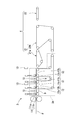
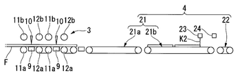
- FIG. 1 is a schematic diagram illustrating an example of an optical film transport device according to the first embodiment of the present invention.
- FIG. 2 is a schematic diagram showing a main part of the optical film transport device of the present embodiment.
- the conveyance apparatus 1 shown in FIG. 1 conveys optical films, such as a polarizing film and retardation film, which are affixed on the board
- An optical film will not be specifically limited if it is a strip
- the conveying apparatus 1 has the supply part 2 which feeds and supplies the strip
- (Cutting unit 10) an intermittent transport unit 3A that intermittently transports the polarizing film F cut to a predetermined length, and a transport mechanism 4 that transports the polarizing film F transported from the intermittent transport unit 3A continuously.
- the unloading mechanism 5 for unloading the polarizing film F transported from the transport mechanism 4 to the next process and the control unit 6 for performing overall control of these mechanisms are included.
- intermittent conveyance is conveyance including temporarily stopping the polarizing film F in the process of conveying the polarizing film F.
- continuously transporting refers to transporting that continues feeding the polarizing film F without stopping the polarizing film F in the process of transporting the polarizing film F.
- an original fabric roll 7 in which a strip-shaped polarizing film F is rolled is loaded on a bobbin 8.
- the bobbin 8 is connected to a driving device such as a motor and is rotatable.
- a dancer roller D is disposed between the supply unit 2 and the cutting mechanism 3.
- the dancer roller D is a polarizing film supplied from the supply unit 2 while the polarizing film F sucked and held by the suction table 9 of the cutting mechanism 3 is cut by the laser device (cutting unit) 10 and the suction holding is released. Absorbs F feed amount.
- a plurality of rollers that form a transport path for the polarizing film F are disposed between the supply unit 2 and the cutting mechanism 3.
- the side approaching the starting point (supply unit 2) of the transport path with respect to an arbitrary position on the transport path is referred to as the upstream side
- the side approaching the end point of the transport path (unloading mechanism 5) is referred to as the downstream side.
- the cutting mechanism 3 sandwiches the suction table 9 that sucks and holds the polarizing film F from the back surface, the laser device (cutting unit) 10 that emits a laser that cuts the polarizing film F, and the laser device 10. And a pair of gripping rollers 11 and 12 that grip the polarizing film F on the upstream side and the downstream side, and an alignment camera 13 for confirming the alignment of the polarizing film F.
- the cutting mechanism 3 has two sets of the laser device 10, the pair of gripping rollers 11 and 12, and the alignment camera 13. That is, in this embodiment, the polarizing film F supplied from the supply unit 2 is simultaneously cut at two positions at a predetermined cutting action position, and the single-piece polarizing film F is cut into two pieces by one cutting operation. Transport.
- FIG. 3 is a cross-sectional view showing the main part of the cutting mechanism 3. In FIG. 3, only one set is illustrated for convenience among the two sets of configurations described above.
- two holding blocks 9 a and 9 b having the same height are fixed to the upper surface of the suction table 9 in close proximity along the conveying direction of the polarizing film F. That is, the suction groove 14 orthogonal to the conveyance direction of the polarizing film F is formed by the opposing inner walls of the holding blocks 9a and 9b.
- the suction groove 14 serves as a scanning path for laser emitted from the laser device 10.
- the position where the laser is scanned (position where the suction groove 14 is formed) is the cutting action position of the polarizing film F.
- the laser device 10 is horizontally movable so as to cut the polarizing film F along the suction groove 14 (a direction orthogonal to the conveying direction of the polarizing film F).
- the gripping rollers 11 and 12 are composed of drive rollers 11a and 12a and elevating rollers 11b and 12b, which are opposed to each other with the polarizing film F interposed therebetween.
- the gripping rollers 11 and 12 are configured, for example, by covering the surface of a core made of metal with an elastic material such as urethane (hardness of about 30 to 90).
- the configuration of the gripping rollers 11 and 12 is not limited to this, and a metal roller, a rubber roller, or the like can be used in appropriate combination as necessary.
- the driving rollers 11a and 12a are disposed on the lower surface side of the polarizing film F.
- the driving rollers 11a and 12a are connected to a driving device such as a motor so that the polarizing film F can be fed out.
- the elevating rollers 11b and 12b are arranged on the upper surface side of the polarizing film F.
- the raising / lowering of the raising / lowering rollers 11b and 12b is performed by an air cylinder 20 connected via a rod 19 to a bracket 18 screwed to the central axis of the rollers.
- the elevating rollers 11b and 12b move up and down over an upper standby position and an operating position for gripping the polarizing film F in cooperation with the driving rollers 11a and 12a.
- the alignment camera 13 is disposed above the polarizing film F. From the imaging result of the alignment camera 13, it can be confirmed whether the polarizing film F is accurately aligned, such as whether the polarizing film F is sent out until it reaches a predetermined cutting action position.
- the gripping rollers 11 and 12 function as an intermittent conveyance unit 3A that intermittently conveys the polarizing film F cut to a predetermined length to the conveyance mechanism 4 on the downstream side.
- the transport mechanism 4 is disposed on the downstream side of the first continuous transport conveyor 21 and the first continuous transport conveyor (transport section) 21 disposed on the downstream side of the intermittent transport section 3 ⁇ / b> A.
- Second continuous transfer conveyor (transfer unit) 22 The 1st continuous conveyance conveyor 21 conveys continuously, receiving the polarizing film F conveyed intermittently from 3A of intermittent conveyance parts.
- the second continuous conveyor 22 continuously conveys the polarizing film F conveyed from the first continuous conveyor 21 while receiving it.
- the first continuous conveyer 21 includes a first conveyer (conveyor) 21a disposed on the downstream side of the intermittent conveyer 3A, and a second conveyer (conveyor) disposed on the downstream side of the first conveyer 21a. ) 21b.
- the first transport conveyor 21a and the second transport conveyor 21b in the present embodiment are set to such a length that the two polarizing films F cut by the cutting mechanism 3 and fed from the intermittent transport section 3A can be plane-held at a predetermined pitch. ing.
- the unloading mechanism 5 is configured by a roller conveyor continuously disposed below the end (downstream side) of the transport mechanism 4.
- a tray 15 for collecting the polarizing film F falling from the transport mechanism 4 (second continuous transport conveyor 22) is disposed at the start end portion of the carry-out mechanism 5.
- the control unit 6 transfers the single-piece polarizing film F from the intermittent conveyance unit 3A to the first conveyance conveyor 21a downstream of the intermittent conveyance unit 3A, the end of one intermittent conveyance process in the intermittent conveyance unit 3A is completed.
- the feeding of the single-piece polarizing film F is controlled so that the rear end of the polarizing film F is separated from the intermittent conveyance unit 3A.
- the cut polarizing film F is fed so that the rear end thereof exceeds the intermittent transport unit 3A during the next intermittent transport, and is delivered to the first transport conveyor 21a downstream of the intermittent transport unit 3A.
- “Send out beyond the intermittent conveyance part 3A” means that the rear end of the cut sheet polarizing film F is separated from the intermittent conveyance part 3A, that is, the rear end of the cut sheet polarizing film F Means to be separated from the conveyance roller located on the most downstream side of the intermittent conveyance unit 3A. Thereby, the polarizing film F after cutting
- control unit 6 When the control unit 6 delivers the polarizing film F from the intermittent transport unit 3A to the first transport conveyor 21a, the control unit 6 changes the transport speed of the polarizing film F in the first transport conveyor 21a to the transport speed of the polarizing film F in the intermittent transport unit 3A. Move closer.
- the control unit 6 When the control unit 6 delivers the polarizing film F from the intermittent transport unit 3A to the first transport conveyor 21a, the control unit 6 changes the transport speed of the polarizing film F in the first transport conveyor 21a to the transport speed of the polarizing film F in the intermittent transport unit 3A. It is desirable to control so that they are approximately the same.
- “substantially match” means the speed at which the polarizing film F is transported by the intermittent transport section 3A (drive rollers 11a, 12a) and the speed at which the polarizing film F is transported by the first transport conveyor 21a. This means that the polarizing film F conveyed between the two may be slightly different as long as no significant rubbing occurs.
- the ratio V2 / V1 between the speed V1 when the polarizing film F is transported by the intermittent transport unit 3A and the speed V2 when the polarizing film F is transported by the first transport conveyor 21a is 0.8 / 1 or more and 1.2. If the range is less than or equal to / 1, it can be said that the speeds of the two are almost the same. If it is such a range, the rubbing of the polarizing film F by the conveyance speed difference of 3 A of intermittent conveyance parts and the 1st conveyance conveyor 21a can fully be suppressed.
- the control unit 6 separates the polarizing film F delivered from the intermittent conveying unit 3A to the first conveying conveyor 21a, and the trailing end of the polarizing film is separated from the leading end of the polarizing film F which is subsequently delivered to the first conveying conveyor 21a. Accelerate to do. That is, after delivering the sheet of polarizing film F from the intermittent conveying unit 3A to the first conveying conveyor 21a downstream of the intermittent conveying unit 3A, the conveying speed of the sheet polarizing film F is changed from the intermittent conveying unit 3A.
- the conveyance speed of the first conveyance conveyor 21a is increased so as to be higher than the conveyance speed of the single-piece polarization film F when the single-sheet polarization film F is delivered to the first conveyance conveyor 21a. Thereby, on the 1st conveyance conveyor 21a, the two polarizing films F after a cutting
- the controller 6 determines the conveying speed of the polarizing film F on the first conveying conveyor 21a to convey the polarizing film F on the second conveying conveyor 21b. It is desirable to approximately match the speed.
- “substantially match” is based on the same idea as V2 / V1 described above, and the transport speed of the polarizing film F on the first transport conveyor 21a and the transport of the polarizing film F on the second transport conveyor 21b. If the speed ratio is in the range of 0.8 / 1 or more and 1.2 / 1 or less, it can be said that the speeds of both are almost the same. And the polarizing film F accelerated by the 1st conveyance conveyor 21a is delivered to the 2nd conveyance conveyor 21b.
- the control unit 6 sends out the rear end of the polarizing film F at the head of the second transport conveyor 21b delivered from the first transport conveyor 21a so as to exceed the second transport conveyor 21b, and downstream of the second transport conveyor 21b.
- the polarizing film F is placed on the second continuous transport conveyor 22 on the downstream side beyond the second transport conveyor 21b.
- the transport speed of the polarizing film F on the second transport conveyor 21b is made closer to the transport speed of the polarizing film F on the second continuous transport conveyor 22.
- control unit 6 When the control unit 6 delivers the polarizing film F from the second transport conveyor 21b to the second continuous transport conveyor 22, the control unit 6 sets the transport speed of the polarizing film F in the second transport conveyor 21b to the polarizing film F in the second continuous transport conveyor 22. It is desirable to perform control so as to substantially match the conveyance speed.
- substantially match means that the speed when the polarizing film F is transported at a reduced speed by the second transport conveyor 21b and the speed when the polarizing film F is transported by the second continuous transport conveyor 22 are It means that the polarizing film F conveyed across the surface may be slightly different as long as no significant rubbing occurs.
- the ratio V3 / V2b between the speed V2b when the polarizing film F is transported at a reduced speed on the second transporting conveyor 21b and the speed V3 when transporting the polarizing film F on the second continuous transporting conveyor 22 is 0.8 / 1 or more. If it is in the range of 1.2 / 1 or less, it can be said that the speeds of the two are almost the same. If it is such a range, the rubbing of the polarizing film F by the conveyance speed difference of the 2nd conveyance conveyor 21b and the 2nd continuous conveyance conveyor 22 can fully be suppressed.
- the control unit 6 includes a computer system.
- This computer system includes an arithmetic processing unit 6a such as a CPU and a storage unit 6b such as a memory or a hard disk.
- the control unit 6 includes an interface capable of executing communication with an external device of the computer system.
- the control unit 6 may be connected to an input device that can input an input signal.
- the input device includes an input device such as a keyboard and a mouse, or a communication device that can input data from a device external to the computer system.
- the control unit 6 may include a display device such as a liquid crystal display that indicates the operation status of each unit of the transport device 1 or may be connected to the display device.
- the storage unit 6b of the control unit 6 stores a program that causes the arithmetic processing unit 6a to control each unit of the transport device 1 so that each unit of the transport device 1 performs processing for accurately transporting the polarizing film F. ing.
- Various types of information including programs recorded in the storage unit 6b can be read by the arithmetic processing unit 6a of the control unit 6.
- the control unit 6 may include a logic circuit such as an ASIC that executes various processes required for controlling each unit of the transport apparatus 1.
- data (recipe) for conveying the polarizing film F is set in the storage unit 6b of the control unit 6 in advance.
- the length of the polarizing film F in a single sheet is 406.6 mm
- the pitch P (the distance between the trailing edge of the leading polarizing film F and the leading edge of the subsequent polarizing film F in the conveying process) is 51.4 mm. Is set in the storage unit 6b.
- the gap of the 2nd conveyance conveyor 21b and the 2nd continuous conveyance conveyor 22 is a polarizing film. It is set to a pitch P or less of F.
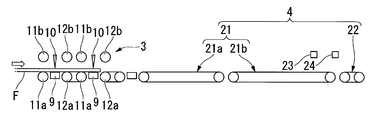
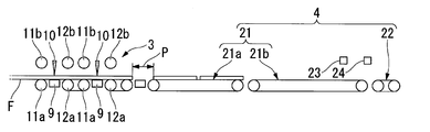
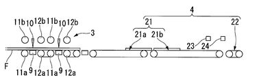
- FIGS. 4A to 4E and FIGS. 5A to 5E are explanatory views showing the operation of the transport apparatus 1 of the present embodiment.
- FIG.6 and FIG.7 is a flowchart of the conveyance method of the polarizing film of this embodiment.
- belt-shaped polarizing film F using the conveying apparatus 1 is demonstrated.
- the original roll 7 of the polarizing film F to be used is loaded into the supply unit 2.
- the operator makes initial settings using the operation panel or the like (step S1 shown in FIG. 6). For example, the cutting length, the thickness, the supply speed, the laser output and the focal depth of the polarizing film F, the feeding speed of the driving roller 12a, the transport speed of the first transport conveyor 21a, the transport speed of the second transport conveyor 21b, and the second continuous The conveyance speed of the conveyance conveyor 22 is set.
- the supply of the polarizing film F from the raw roll 7 is started, and the rotational speed of a drive shaft such as a motor provided in the supply unit 2 is detected by a sensor such as a rotary encoder (not shown).
- the polarizing film F is supplied from the supply unit 2 (step S2 shown in FIG. 6).
- the polarizing film F supplied from the supply unit 2 is conveyed to the cutting mechanism 3 (see FIG. 4A).
- the elevating rollers 11b and 12b are operated under the control of the control unit 6.
- the polarizing film F is gripped on both sides of the suction table 9.
- the air cylinder 20 connected to both rollers 11b and 12b is synchronized, and simultaneously lowers both rollers 11b and 12b (see FIG. 4B).
- the suction device (not shown) is operated in this state, and the polarizing film F is sucked and held on the suction table 9.
- the dancer roller D is operated under the control of the control unit 6. Thereby, it adjusts so that the polarizing film F supplied continuously from the supply part 2 may not be drawn out after the dancer roller D.
- the laser device 10 When the polarizing film F is sucked and held on the suction table 9, the laser device 10 is operated under the control of the control unit 6 (see FIG. 4C). Thereby, the polarizing film F sucked and held on the suction table 9 is cut along the suction grooves 14. As a result, the strip-shaped polarizing film F is cut into sheets having a predetermined length (step S3 shown in FIG. 6).
- the suction of the suction table 9 to the polarizing film F and the gripping by the gripping rollers 11 and 12 are released (see FIG. 4D).
- the control rollers 6 control the drive rollers 11a, 12a, the first continuous transport conveyor 21 (the first transport conveyor 21a, the second transport conveyor 21b), and the second continuous transport conveyor 22 to operate. To do.
- the control unit 6 reads the optimum recipe from the storage unit 6b based on the initial setting. In accordance with this recipe, the control unit 6 is driven so that the single-sheet polarizing film F that is intermittently drawn from the upstream cutting mechanism 3 is plane-held at a predetermined pitch with respect to the polarizing film F on the first conveyor 21a. Operation control of the rollers 11a and 12a and the 1st conveyance conveyor 21a is carried out.
- the intermittent transport unit 3A transports the cut polarizing film F to the first transport conveyor 21a (step S4 shown in FIG. 6).
- the polarizing film F is transported at the first transport conveyor 21a and the polarizing film F is transported at the intermittent transport unit 3A when the polarizing film F is transferred from the intermittent transport unit 3A to the first transport conveyor 21a.
- the speed V1 when the polarizing film F is transported by the intermittent transport unit 3A is 90 m / min
- the speed V2 when the polarizing film F is transported by the first transport conveyor 21a is 90 m / min.
- the speeds V1 and V2 are controlled to be equal to each other.
- the polarizing film F When the polarizing film F is transferred from the intermittent conveying unit 3A to the first conveying conveyor 21a, it is determined whether or not the rear end of the polarizing film F after being cut exceeds the intermittent conveying unit 3A (step S5 shown in FIG. 6). ). For example, the determination as to whether or not the rear end of the polarizing film F after cutting has exceeded the intermittent conveyance unit 3 ⁇ / b> A is performed by a time table stored in advance in the storage unit 6 b of the control unit 6.
- a predetermined length when the polarizing film F is cut in the initial setting, the rotation speeds of the driving rollers 11a and 12a in the intermittent conveyance unit 3A (conveying speed of the polarizing film F), and the intermittent conveyance unit 3A and the first conveyance The distance between the conveyor 21a is set. Thereby, it can be determined whether how much time the polarizing film F is conveyed in the intermittent conveyance part 3A, if the rear end of the polarizing film F after a cutting
- Step S6 the operation
- Step S6 the polarizing film F after cutting
- the polarizing film F transferred to the first transport conveyor 21a by the control of the control unit 6 has the rear end next to the first transport conveyor 21a. Is accelerated so as to be separated by a predetermined pitch P from the tip of the polarizing film F delivered to (see FIG. 5A, step S8 shown in FIG. 7).
- the speed V2a after accelerating the polarizing film F by the first transport conveyor 21a is 103.5 m / min, and the speed V1 (90 m / min) when the polarizing film F is transported by the intermittent transport section 3A.
- the speed V2a of the polarizing film F after acceleration is controlled to be larger than that (V2a> V1).
- the conveyance speed of the polarizing film F in the 1st conveyance conveyor 21a at the time of delivering the polarizing film F from the 1st conveyance conveyor 21a to the 2nd conveyance conveyor 21b, and the polarizing film in the 2nd conveyance conveyor 21b Control is performed so that the conveyance speed of F substantially matches.
- the polarizing film F accelerated by the 1st conveyance conveyor 21a is delivered to the 2nd conveyance conveyor 21b at a fixed speed
- the accelerated polarizing film F is transported by a predetermined distance on the second transport conveyor 21b (see FIG. 5B). Thereafter, under the control of the control unit 6, the transport speed of the polarizing film F in the second transport conveyor 21 b when the polarizing film F is transferred from the second transport conveyor 21 b to the second continuous transport conveyor 22 is set to the second continuous transport conveyor 22. It can be brought close to the conveyance speed of the polarizing film F. Specifically, when the tip of the accelerated polarizing film F reaches the predetermined position K2 on the second transport conveyor 21b, the polarizing film F on the second transport conveyor 21b is decelerated under the control of the control unit 6 (FIG. Refer to 5C, step S9 shown in FIG.
- the fact that the tip of the polarizing film F has reached the predetermined position K2 is confirmed by the deceleration sensor 23 disposed above the second transport conveyor 21b.
- the deceleration sensor 23 detects the leading end of the accelerated polarizing film F, the accelerated polarizing film F is decelerated under the control of the control unit 6.
- the decelerated polarizing film F is conveyed to the 2nd continuous conveyance conveyor 22 (refer FIG. 5D, step S10 shown in FIG. 7).
- the conveying speed of the polarizing film F on the second conveying conveyor 21 b and the polarizing film on the second continuous conveying conveyor 22 are determined. Control is performed so that the conveyance speed of F substantially matches.
- “substantially coincides” is a ratio between the speed V2b of the polarizing film F after deceleration in the second transport conveyor 21b and the speed V3 when the polarizing film F is transported by the second continuous transport conveyor 22.
- V3 / V2b is in the range of 0.8 / 1 to 1.2 / 1.
- the speed V2b after decelerating the polarizing film F by the second transport conveyor 21b is 50 m / min
- the speed V3 when transporting the polarizing film F by the second continuous transport conveyor 22 is 60 m / min. Control is performed so that the conveyance speeds V2b and V3 are substantially the same.
- step S11 it is determined whether or not the rear end of the polarizing film F after deceleration has exceeded the second conveyor 21b (step S11 shown in FIG. 7). For example, whether or not the rear end of the polarizing film F after deceleration exceeds the second transport conveyor 21b is confirmed by the acceleration sensor 24 disposed above the second transport conveyor 21b.
- the acceleration sensor 24 detects the rear end of the polarizing film F after deceleration, the transport speed of the second transport conveyor 21b is switched under the control of the control unit 6.
- the conveyance speed of the second conveying conveyor 21b is controlled by the control unit 6 from 50 m / min during deceleration to 103.5 m / min during acceleration. Is switched to. Thereby, it becomes possible to smoothly deliver the polarizing film F accelerated by the first transport conveyor 21a to the second transport conveyor 21b.
- Step S12 the operation which delivers this polarizing film F to the 2nd continuous conveyance conveyor 22 is completed ( Step S12 shown in FIG. Thereby, the polarizing film F after deceleration is placed on the second continuous transport conveyor 22 on the downstream side beyond the second transport conveyor 21b (see FIG. 5E).
- the polarizing film F delivered to the second continuous conveyance conveyor 22 is conveyed toward the carry-out mechanism 5.
- a tray 15 is disposed at the start end of the unloading mechanism 5. Accordingly, the polarizing film F falling from the end position of the transport mechanism 4 is sequentially stored in the tray 15.
- the polarizing film F that is intermittently fed out from the cutting mechanism 3 is fed so that the rear end thereof exceeds the intermittent transport unit 3A during the next intermittent transport. It is delivered to the first transport conveyor 21a that continues downstream of the intermittent transport unit 3A. For this reason, it can avoid that the front-end
- the conveying speed of the polarizing film F in the first conveying conveyor 21a can be made closer to the conveying speed of the polarizing film F in the intermittent conveying unit 3A.
- the delivery from the intermittent conveyance unit 3A to the first conveyance conveyor 21a becomes smooth. As a result, it is possible to avoid the polarizing film F from being rubbed due to a speed difference between the intermittent conveyance unit 3A and the first conveyance conveyor 21a.
- the transport speed of the polarizing film F on the second transport conveyor 21b is the transport speed of the polarizing film F on the second continuous transport conveyor 22. Therefore, the delivery from the second conveyor 21b to the second continuous conveyor 22 becomes smooth. As a result, it is possible to avoid the polarizing film F from being rubbed due to the speed difference between the second conveyor 21b and the second continuous conveyor 22. Accordingly, it is possible to avoid rubbing of the polarizing film F in the process of transporting the polarizing film F, and to suppress deterioration of the quality of the polarizing film F.
- the polarizing film F can be transferred more smoothly from the intermittent transfer section 3A to the first transfer conveyor 21a. Thereby, it can avoid that the polarizing film F rubs by the speed difference between the intermittent conveyance part 3A and the 1st conveyance conveyor 21a.
- the speed V2b after the polarizing film F is decelerated by the second transport conveyor 21b and the speed V3 when the polarizing film F is transported by the second continuous transport conveyor 22 are controlled so as to substantially coincide,
- the film F can be delivered more smoothly from the second conveyor 21b to the second continuous conveyor 22. Thereby, it can avoid that the polarizing film F rubs by the speed difference between the 2nd conveyance conveyor 21b and the 2nd continuous conveyance conveyor 22.
- the rear end of the polarizing film F delivered to the first transport conveyor 21a is accelerated so as to be separated from the front end of the polarizing film F delivered to the first transport conveyor 21a, it is cut by the cutting mechanism 3. It is possible to avoid collision of the front and rear polarizing films F when the polarizing films F are sent to the first conveyor 21a.
- the polarizing film F is accelerated in the 1st conveyance conveyor 21a, and the polarizing film F accelerated in the 2nd conveyance conveyor 21b is decelerated. That is, the conveyance speed of the polarizing film F can be variably controlled by the first conveyance conveyor 21a and the second conveyance conveyor 21b separately. Therefore, variably controlling the conveyance speed of the polarizing film F can be easily realized.
- the case where the number of sheets of polarizing film F cut by the cutting mechanism 3 is two is described as an example, but the present invention is not limited to this.
- the number of sheets of polarizing film F cut by the cutting mechanism 3 may be one, or may be three or more.
- the polarizing film is described as an example of the optical film.
- the present invention is not limited to this, and the present invention can also be applied to a polarizing film with a separator.
- the 1st continuous conveyance conveyor 21 gave and demonstrated the example comprised provided with the 1st conveyance conveyor 21a and the 2nd conveyance conveyor 21b, it is not restricted to this.
- the first continuous transfer conveyor 21 may be configured to include only one transfer conveyor, or may be configured to include three or more transfer conveyors.
- the present invention can be applied to a configuration in which the polarizing film F is accelerated on the first transport conveyor 21a and the accelerated polarizing film F is decelerated.
- FIGS. 9A to 9E, and FIGS. 10A to 10B are explanatory views showing the operation of the transport apparatus according to the second embodiment of the present invention.
- belt-shaped polarizing film F using the conveying apparatus of 2nd Embodiment is demonstrated.
- the operation of the transport device of the present embodiment is that the number of sheets of polarizing film F placed on the first transport conveyor 21a is one, the polarizing film F is accelerated on the first transport conveyor 21a and after acceleration. The point which decelerates the polarizing film F of this differs from the operation
- the polarizing film F supplied from the supply unit 2 is conveyed to the cutting mechanism 3 (see FIG. 8A).
- the elevating rollers 11b and 12b are operated under the control of the control unit 6.
- the polarizing film F is gripped on both sides of the suction table 9.
- the air cylinder 20 connected to both the rollers 11b and 12b synchronizes and simultaneously lowers both the rollers 11b and 12b (see FIG. 8B).
- the suction device (not shown) is operated in this state, and the polarizing film F is sucked and held on the suction table 9.
- the dancer roller D is operated under the control of the control unit 6. Thereby, it adjusts so that the polarizing film F supplied continuously from the supply part 2 may not be drawn out after the dancer roller D.
- the laser device 10 When the polarizing film F is sucked and held on the suction table 9, the laser device 10 is operated under the control of the control unit 6 (see FIG. 8C). Thereby, the polarizing film F sucked and held on the suction table 9 is cut along the suction grooves 14. As a result, the strip-shaped polarizing film F is cut into sheets (one sheet) having a predetermined length.
- the suction of the suction table 9 to the polarizing film F and the gripping by the gripping rollers 11 and 12 are released (see FIG. 8D).
- the control rollers 6 control the drive rollers 11a, 12a, the first continuous transport conveyor 21 (the first transport conveyor 21a, the second transport conveyor 21b), and the second continuous transport conveyor 22 to operate. To do.
- the polarizing film F after cutting is placed on the first transport conveyor 21a on the downstream side beyond the intermittent transport section 3A (see FIG. 8E).
- the polarizing film F transferred to the first transport conveyor 21a by the control of the control unit 6 has the rear end next to the first transport conveyor 21a. Is accelerated so as to be separated from the front end of the polarizing film F delivered to the predetermined pitch P (see FIG. 9A).
- the speed V2a after accelerating the polarizing film F by the first transport conveyor 21a is 103.5 m / min, and the speed V1 (90 m / min) when the polarizing film F is transported by the intermittent transport section 3A.
- the speed V2a of the polarizing film F after acceleration is controlled to be larger than that (V2a> V1).
- the accelerated polarizing film F travels on the first conveyor 21a by a predetermined distance (see FIG. 9B). Thereafter, under the control of the control unit 6, when the polarizing film F is transferred from the first conveying conveyor 21a to the second conveying conveyor 21b, the conveying speed of the polarizing film F in the first conveying conveyor 21a is the polarizing film in the second conveying conveyor 21b. F can be brought close to the conveyance speed. Specifically, when the tip of the accelerated polarizing film F reaches the predetermined position K3 on the first transport conveyor 21a, the accelerated polarizing film F is decelerated under the control of the control unit 6 (see FIG. 9C). .
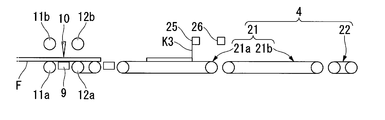
- the decelerating sensor 25 disposed above the first conveyor 21a It is confirmed by the decelerating sensor 25 disposed above the first conveyor 21a that the tip of the accelerated polarizing film F has reached the predetermined position K3.
- the deceleration sensor 25 detects the tip of the accelerated polarizing film F, the accelerated polarizing film F is decelerated under the control of the control unit 6.
- substantially coincides means a ratio V5 / V4 between the conveyance speed V4 of the polarizing film F after deceleration on the first conveyance conveyor 21a and the speed V5 when the polarization film F is conveyed on the second conveyance conveyor 21b. Is in the range of 0.8 / 1 to 1.2 / 1.
- the speed V4 after decelerating the polarizing film F by the first transport conveyor 21a is 42 m / min
- the speed V5 when transporting the polarizing film F by the second transport conveyor 21b is 50 m / min
- Control is performed so that the conveyance speeds V4 and V5 substantially coincide with each other.
- the decelerated polarizing film F is conveyed from the first conveyor 21 to the second conveyor (see FIG. 9D). At this time, it is determined whether or not the rear end of the polarizing film F after deceleration has exceeded the first conveyor 21a. For example, whether or not the rear end of the polarizing film F after deceleration exceeds the first transport conveyor 21a is determined by the acceleration sensor 26 disposed above the first transport conveyor 21a. When the acceleration sensor 26 detects the rear end of the polarizing film F after being decelerated, the conveyance speed of the first conveyance conveyor 21a is switched under the control of the control unit 6.
- the transport speed of the first transport conveyor 21a is switched from 42 m / min during deceleration to 90 m / min during normal operation. Thereby, it becomes possible to receive smoothly the polarizing film F sent out from 3 A of intermittent conveyance parts.
- movement which delivers the polarizing film F to the 2nd conveyance conveyor 21b is completed.
- the polarizing film F after deceleration passes over the 1st conveyance conveyor 21a, and is mounted on the 2nd conveyance conveyor 21b of a downstream (refer FIG. 9E).
- the polarizing film F delivered to the second conveyor 21b is conveyed toward the second continuous conveyor 22 (see FIG. 10A).
- control unit 6 Under the control of the control unit 6, when the polarizing film F is transferred from the second conveying conveyor 21 b to the second continuous conveying conveyor 22, the conveying speed of the polarizing film F on the second conveying conveyor 21 b and the polarizing film on the second continuous conveying conveyor 22 are determined. Control is performed so that the conveyance speed of F substantially matches.
- a tray 15 is disposed at the start end of the unloading mechanism 5. Accordingly, the polarizing film F falling from the end position of the transport mechanism 4 is sequentially stored in the tray 15.
- the present embodiment it is possible to avoid the tip portion of the polarizing film F cut by the intermittent conveyance unit 3A from being stopped and rubbed while being in contact with the first conveyance conveyor 21a. Moreover, when sending out the polarizing film F cut
- an optical film transport method and a transport apparatus that can avoid rubbing of the optical film in the process of transporting the optical film and suppress deterioration of the quality of the optical film.
Landscapes
- Physics & Mathematics (AREA)
- Engineering & Computer Science (AREA)
- Mechanical Engineering (AREA)
- General Physics & Mathematics (AREA)
- Optics & Photonics (AREA)
- Nonlinear Science (AREA)
- Chemical & Material Sciences (AREA)
- Crystallography & Structural Chemistry (AREA)
- Polarising Elements (AREA)
- Delivering By Means Of Belts And Rollers (AREA)
- Absorbent Articles And Supports Therefor (AREA)
Abstract
この光学フィルムの搬送方法は、光学フィルムを間欠搬送部(3A)により間欠的に搬送する間欠搬送工程と;前記間欠搬送部(3A)から搬送されてきた前記光学フィルムを複数の搬送部において連続的に搬送する連続搬送工程とを含み、前記間欠搬送部(3A)から前記搬送部に前記光学フィルムを受け渡す際に、前記間欠搬送部(3A)により前記搬送部に向けて搬送される前記光学フィルムの搬送速度である第1の搬送速度と前記搬送部において搬送される前記光学フィルムの搬送速度である第2の搬送速度とが近付くように制御し;前記複数の搬送部のうち、上流側搬送部から下流側搬送部に前記光学フィルムを受け渡す際に、前記上流側搬送部から前記下流側搬送部に向けて搬送される前記光学フィルムの搬送速度である第3の搬送速度と前記下流側搬送部上で搬送される前記光学フィルムの搬送速度である第4の搬送速度とが近付くように制御する。
Description
本発明は、光学フィルムの搬送方法および搬送装置に関する。本願は、2011年6月2日に、日本に出願された特願2011-124264号に基づき優先権を主張し、その内容をここに援用する。
従来、液晶パネルなどの基板に貼り付ける偏光フィルム、位相差フィルムなどの光学フィルムが知られている。このような光学フィルムの搬送方法として、帯状の光学フィルムを所定長さの枚葉に切断して搬送する方法が提案されている。
例えば特許文献1では、帯状の光学フィルムを送り出しながら切断部で所定長さの枚葉に切断し、切断部から間欠的に搬送された枚葉の光学フィルムを切断部の下流側に続く間欠搬送部および連続搬送部で搬送している。
上述のような光学フィルムの搬送方法においては、光学フィルムの受け渡し箇所が、切断部から間欠搬送部と、間欠搬送部から連続搬送部との2箇所存在する。そのため、切断部と間欠搬送部との間あるいは間欠搬送部と連続搬送部との間に大きな搬送速度の差が存在すると、光学フィルムを受け渡す際に光学フィルムに擦れが生じ、光学フィルムの品質を低下させるおそれがある。
本発明はこのような事情に鑑みてなされたものであって、光学フィルムの搬送過程において光学フィルムの擦れを回避し、光学フィルムの品質の低下を抑制することが可能な光学フィルムの搬送方法および搬送装置を提供することを目的とする。
上記の課題を解決して係る目的を達成するために、本発明は以下の手段を採用した。
(1)すなわち、本発明の第一の態様に係る光学フィルムの搬送方法は、光学フィルムを搬送する光学フィルムの搬送方法であって、帯状の光学フィルムを切断部において所定長さの前記光学フィルムに切断する切断工程と、切断された前記光学フィルムを間欠搬送部により間欠的に搬送する間欠搬送工程と、前記間欠搬送部から搬送されてきた前記光学フィルムを前記間欠搬送部の下流側に続く複数の搬送部において停止させることなく連続的に搬送する連続搬送工程とを含み、前記間欠搬送部から前記搬送部に前記光学フィルムを受け渡す際に、前記間欠搬送部により前記搬送部に向けて搬送される前記光学フィルムの搬送速度である第1の搬送速度と前記搬送部において搬送される前記光学フィルムの搬送速度である第2の搬送速度とが近付くように、前記第2の搬送速度を可変に制御し、前記複数の搬送部のうち、上流側搬送部から下流側搬送部に前記光学フィルムを受け渡す際に、前記上流側搬送部から前記下流側搬送部に向けて搬送される前記光学フィルムの搬送速度である第3の搬送速度と前記下流側搬送部上で搬送される前記光学フィルムの搬送速度である第4の搬送速度とが近付くように、前記第3の搬送速度または前記第4の搬送速度を可変に制御する。
(1)すなわち、本発明の第一の態様に係る光学フィルムの搬送方法は、光学フィルムを搬送する光学フィルムの搬送方法であって、帯状の光学フィルムを切断部において所定長さの前記光学フィルムに切断する切断工程と、切断された前記光学フィルムを間欠搬送部により間欠的に搬送する間欠搬送工程と、前記間欠搬送部から搬送されてきた前記光学フィルムを前記間欠搬送部の下流側に続く複数の搬送部において停止させることなく連続的に搬送する連続搬送工程とを含み、前記間欠搬送部から前記搬送部に前記光学フィルムを受け渡す際に、前記間欠搬送部により前記搬送部に向けて搬送される前記光学フィルムの搬送速度である第1の搬送速度と前記搬送部において搬送される前記光学フィルムの搬送速度である第2の搬送速度とが近付くように、前記第2の搬送速度を可変に制御し、前記複数の搬送部のうち、上流側搬送部から下流側搬送部に前記光学フィルムを受け渡す際に、前記上流側搬送部から前記下流側搬送部に向けて搬送される前記光学フィルムの搬送速度である第3の搬送速度と前記下流側搬送部上で搬送される前記光学フィルムの搬送速度である第4の搬送速度とが近付くように、前記第3の搬送速度または前記第4の搬送速度を可変に制御する。
(2)上記(1)に記載の光学フィルムの搬送方法では、前記間欠搬送部から前記搬送部に前記光学フィルムを受け渡す際に、前記間欠搬送部における一の前記間欠搬送工程の終了時点において、前記間欠搬送部から前記光学フィルムの後端が離間するように前記光学フィルムが送り出されてもよい。
(3)上記(1)または(2)に記載の光学フィルムの搬送方法では、前記間欠搬送部から前記搬送部に前記光学フィルムを受け渡す際に、前記第2の搬送速度の前記第1の搬送速度に対する比を0.8以上1.2以下としてもよい。
(4)上記(1)~(3)のいずれか一項に記載の光学フィルムの搬送方法では、前記上流側搬送部から前記下流側搬送部に前記光学フィルムを受け渡す際に、前記第3の搬送速度の前記第4の搬送速度に対する比を0.8以上1.2以下としてもよい。
(5)上記(1)~(4)のいずれか一項に記載の光学フィルムの搬送方法では、前記間欠搬送部から前記搬送部に前記光学フィルムを受け渡した後、前記光学フィルムの搬送速度が、前記間欠搬送部から前記搬送部に前記光学フィルムが受け渡された際の前記光学フィルムの搬送速度よりも大きくなるように、前記搬送部の搬送速度を大きくしてもよい。
(6)本発明の第二の態様に係る光学フィルムの搬送装置は、光学フィルムを搬送する光学フィルムの搬送装置であって、帯状の光学フィルムを供給する供給部と、前記供給部から供給された帯状の光学フィルムを所定長さの光学フィルムに切断する切断部と、前記所定長さに切断された前記光学フィルムを間欠的に搬送する間欠搬送部と、前記間欠搬送部から搬送されてくる前記光学フィルムを受け取りながら停止させることなく連続的に搬送する複数の搬送部と、前記搬送装置の統括制御を行う制御部とを備え、前記制御部は、前記間欠搬送部からこの間欠搬送部の下流側に続く前記搬送部に前記光学フィルムを受け渡す際に、前記間欠搬送部により前記搬送部に向けて搬送される前記光学フィルムの搬送速度である第1の搬送速度と前記搬送部上で搬送される前記光学フィルムの搬送速度である第2の搬送速度とが近付くように前記第2の搬送速度を可変に制御し、且つ、前記制御部は、前記搬送部のうちの上流側搬送部から下流側搬送部に前記光学フィルムを受け渡す際に、前記上流側搬送部から前記下流側搬送部に向けて搬送される前記光学フィルムの搬送速度である第3の搬送速度と前記下流側搬送部上で搬送される前記光学フィルムの搬送速度である第4の搬送速度とが近付くように前記第3の搬送速度または前記第4の搬送速度を可変に制御する。
(7)上記(6)に記載の光学フィルムの搬送装置では、前記制御部は、前記間欠搬送部から前記搬送部に前記光学フィルムを受け渡す際に、前記間欠搬送部における一の間欠搬送工程の終了時点において、前記間欠搬送部から前記光学フィルムの後端が離間するように前記光学フィルムの送り出しを制御してもよい。
(8)上記(6)または(7)に記載の光学フィルムの搬送装置では、前記制御部は、前記間欠搬送部から前記搬送部に前記光学フィルムを受け渡す際に、前記第2の搬送速度の前記第1の搬送速度に対する比を0.8以上1.2以下とするように制御してもよい。
(9)上記(6)~(8)のいずれか一項に記載の光学フィルムの搬送装置では、前記制御部は、前記上流側搬送部から前記下流側搬送部に前記光学フィルムを受け渡す際に、前記第3の搬送速度の前記第4の搬送速度に対する比を0.8以上1.2以下とするように制御してもよい。
(10)上記(6)~(9)のいずれか一項に記載の光学フィルムの搬送装置では、前記制御部は、前記間欠搬送部から前記搬送部に前記光学フィルムを受け渡した後、前記搬送部における前記光学フィルムの搬送速度を、前記間欠搬送部からこの搬送部に前記光学フィルムが受け渡された際の前記光学フィルムの搬送速度よりも大きくなるように制御してもよい。
本発明によれば、光学フィルムの搬送過程において光学フィルムの擦れを回避し、光学フィルムの品質の低下を抑制することが可能な光学フィルムの搬送方法および搬送装置を提供することができる。
以下、図面を参照しつつ本発明の実施形態を説明するが、本発明は以下の実施形態に限定されるものではない。
以下の全ての図面においては、図面を見やすくするため、各構成要素の寸法や比率などは適宜異ならせてある。また、以下の説明及び図面中、同一又は相当する要素には同一の符号を付し、重複する説明は省略する。
以下の全ての図面においては、図面を見やすくするため、各構成要素の寸法や比率などは適宜異ならせてある。また、以下の説明及び図面中、同一又は相当する要素には同一の符号を付し、重複する説明は省略する。
(第1実施形態)
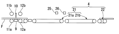
図1は、本発明の第1実施形態の光学フィルムの搬送装置の一例を示す模式図である。図2は、本実施形態の光学フィルムの搬送装置の要部を示す模式図である。
図1に示す搬送装置1は、例えば液晶パネルや有機ELパネルなどの光学表示パネルの基板に貼り付ける偏光フィルム、位相差フィルムなどの光学フィルムを搬送する。光学フィルムは、可撓性を有する帯状の機能性フィルムであれば特に限定されるものではなく、本実施形態では偏光フィルムを例に挙げて説明する。
図1は、本発明の第1実施形態の光学フィルムの搬送装置の一例を示す模式図である。図2は、本実施形態の光学フィルムの搬送装置の要部を示す模式図である。
図1に示す搬送装置1は、例えば液晶パネルや有機ELパネルなどの光学表示パネルの基板に貼り付ける偏光フィルム、位相差フィルムなどの光学フィルムを搬送する。光学フィルムは、可撓性を有する帯状の機能性フィルムであれば特に限定されるものではなく、本実施形態では偏光フィルムを例に挙げて説明する。
図1及び図2に示すように、搬送装置1は、帯状の偏光フィルムFを繰り出し供給する供給部2と、帯状の偏光フィルムFを搬送方向において所定長さの枚葉に切断する切断機構3(切断部10)と、所定長さに切断された偏光フィルムFを間欠的に搬送する間欠搬送部3Aと、間欠搬送部3Aから搬送された偏光フィルムFを連続的に搬送する搬送機構4と、搬送機構4から搬送された偏光フィルムFを次工程に搬出する搬出機構5と、これらの機構の統括制御を行う制御部6と、を含んで構成されている。なお、「間欠的に搬送」とは、偏光フィルムFを搬送する過程で偏光フィルムFをいったん停止させることを含む搬送である。また、「連続的に搬送」とは、偏光フィルムFを搬送する過程で偏光フィルムFを停止させることなく偏光フィルムFの送り出しを継続する搬送である。
供給部2は、帯状の偏光フィルムFをロール状態にした原反ロール7がボビン8に装填されている。ボビン8は、モーターなどの駆動装置に接続されており、回転可能になっている。
供給部2と切断機構3との間には、ダンサローラDが配置されている。ダンサローラDは、切断機構3の吸着テーブル9で吸着保持されている偏光フィルムFがレーザー装置(切断部)10で切断されて吸着保持が解除される間に、供給部2から供給される偏光フィルムFの繰り出し量を吸収する。
また、供給部2と切断機構3との間には、偏光フィルムFの搬送経路を形成する複数のローラが配置されている。以下の説明においては、搬送経路上の任意の位置に対して、搬送経路の始点(供給部2)に近づく側を上流側、搬送経路の終点(搬出機構5)に近づく側を下流側という。
図2に示すように、切断機構3は、偏光フィルムFを裏面から吸着保持する吸着テーブル9と、偏光フィルムFをカットするレーザーを射出するレーザー装置(切断部)10と、レーザー装置10を挟んで上流側と下流側とで偏光フィルムFを把持する一対の把持ローラ11,12と、偏光フィルムFのアライメントを確認するためのアライメントカメラ13と、を備えている。
本実施形態において、切断機構3は、レーザー装置10、一対の把持ローラ11,12、およびアライメントカメラ13をそれぞれ2組有している。すなわち、本実施形態においては、供給部2から供給される偏光フィルムFを所定の切断作用位置で2箇所同時に切断し、枚葉の偏光フィルムFを一回の切断動作で2枚切り出し2枚ずつ搬送する。
図3は、切断機構3の要部を示す断面図である。図3においては、上述した2組の構成のうち便宜上1組のみを図示している。
図3に示すように、吸着テーブル9の上面には高さが同一の2個の保持ブロック9a,9bが、偏光フィルムFの搬送方向に沿って近接して固定されている。つまり、両保持ブロック9a,9bの対向する内側壁によって偏光フィルムFの搬送方向に直交する吸着溝14が形成されている。この吸着溝14は、レーザー装置10から射出されるレーザーの走査経路となる。なお、レーザーが走査される位置(吸着溝14が形成される位置)が偏光フィルムFの切断作用位置となる。
レーザー装置10は、偏光フィルムFを吸着溝14(偏光フィルムFの搬送方向に直交する方向)に沿って切断するよう水平移動可能になっている。
把持ローラ11,12は、偏光フィルムFを挟んで対向配置された、駆動ローラ11a,12aと、昇降ローラ11b,12bと、から構成されている。把持ローラ11,12は、例えば金属からなる芯材の表面にウレタン(硬度30~90程度)などの弾性材が被覆されて構成されている。把持ローラ11,12の構成は、これに限らず、金属ローラやゴムローラなどを必要に応じて適宜組み合わせて用いることができる。
駆動ローラ11a,12aは偏光フィルムFの下面側に配置されている。駆動ローラ11a,12aは、モーターなどの駆動装置に接続されており、偏光フィルムFを繰り出し可能になっている。
昇降ローラ11b,12bは偏光フィルムFの上面側に配置されている。昇降ローラ11b,12bの昇降は、ローラの中心軸にネジ固定されたブラケット18にロッド19を介して連結されたエアーシリンダ20によって行われる。昇降ローラ11b,12bは、上方の待機位置と偏光フィルムFを駆動ローラ11a,12aと協働して把持する作用位置とに亘って昇降する。
アライメントカメラ13は、偏光フィルムFの上方に配置されている。アライメントカメラ13の撮像結果により、偏光フィルムFが所定の切断作用位置に達するまで送り出されているかなど、偏光フィルムFのアライメントが精度よくなされているかを確認することができる。
把持ローラ11,12は、所定長さに切断された偏光フィルムFを下流側の搬送機構4に間欠的に搬送する間欠搬送部3Aとして機能する。
図1及び図2に示すように、搬送機構4は、間欠搬送部3Aの下流側に配置された第1連続搬送コンベア(搬送部)21と、この第1連続搬送コンベア21の下流側に配置された第2連続搬送コンベア(搬送部)22と、を備えている。第1連続搬送コンベア21は、間欠搬送部3Aから間欠的に搬送されてくる偏光フィルムFを受け取りながら連続的に搬送する。第2連続搬送コンベア22は、第1連続搬送コンベア21から搬送されてくる偏光フィルムFを受け取りながら連続的に搬送する。
第1連続搬送コンベア21は、間欠搬送部3Aの下流側に配置された第1搬送コンベア(搬送部)21aと、この第1搬送コンベア21aの下流側に配置された第2搬送コンベア(搬送部)21bと、を備えている。
本実施形態における第1搬送コンベア21aおよび第2搬送コンベア21bは、切断機構3で切断されて間欠搬送部3Aから送り出された2枚の偏光フィルムFを所定ピッチで平面保持できる長さに設定されている。
搬出機構5は、搬送機構4の終端(下流側)下方に連続配置されたローラコンベアにより構成されている。搬出機構5の始端部分には、搬送機構4(第2連続搬送コンベア22)から落下してくる偏光フィルムFを回収するトレー15が配置されている。
制御部6は、間欠搬送部3Aからこの間欠搬送部3Aの下流側に続く第1搬送コンベア21aに枚葉の偏光フィルムFを受け渡す際に、間欠搬送部3Aにおける一の間欠搬送過程の終了時点において、間欠搬送部3Aから偏光フィルムFの後端が離間するように、枚葉の偏光フィルムFの送り出しを制御する。具体的には、切断後の枚葉の偏光フィルムFを後端が次の間欠搬送時に間欠搬送部3Aを越えるよう送り出し、この間欠搬送部3Aの下流側に続く第1搬送コンベア21aに受け渡す。「間欠搬送部3Aを越えるように送り出す」とは、切断後の枚葉の偏光フィルムFの後端が間欠搬送部3Aから離間すること、すなわち、切断後の枚葉の偏光フィルムFの後端が間欠搬送部3Aの最も下流側にある搬送ローラと離間することを意味する。これにより、切断後の偏光フィルムFは、間欠搬送部3Aを越えて下流側の第1搬送コンベア21a上に載置される。
制御部6は、偏光フィルムFを間欠搬送部3Aから第1搬送コンベア21aへ受け渡す際に、第1搬送コンベア21aにおける偏光フィルムFの搬送速度を間欠搬送部3Aにおける偏光フィルムFの搬送速度に近づける。
制御部6は、偏光フィルムFを間欠搬送部3Aから第1搬送コンベア21aへ受け渡す際に、第1搬送コンベア21aにおける偏光フィルムFの搬送速度を間欠搬送部3Aにおける偏光フィルムFの搬送速度に概ね一致させるように制御することが望ましい。ここで、「概ね一致させる」とは、間欠搬送部3A(駆動ローラ11a,12a)で偏光フィルムFを搬送する際の速度と第1搬送コンベア21aで偏光フィルムFを搬送する際の速度とを、両者の間にまたがって搬送される偏光フィルムFに大きな擦れが生じない範囲で、若干異ならせてもよいことを意味する。例えば、間欠搬送部3Aで偏光フィルムFを搬送する際の速度V1と第1搬送コンベア21aで偏光フィルムFを搬送する際の速度V2との比V2/V1が0.8/1以上1.2/1以下の範囲であれば、両者の速度は概ね一致していると言える。このような範囲であれば、間欠搬送部3Aと第1搬送コンベア21aとの搬送速度差による偏光フィルムFの擦れを十分に抑制することができる。
制御部6は、間欠搬送部3Aから第1搬送コンベア21aに受け渡された偏光フィルムFを、この偏光フィルムの後端が次に第1搬送コンベア21aに受け渡される偏光フィルムFの先端と離間するよう加速させる。つまり、間欠搬送部3Aからこの間欠搬送部3Aの下流側に続く第1搬送コンベア21aに枚葉の偏光フィルムFを受け渡した後、枚葉の偏光フィルムFの搬送速度が、間欠搬送部3Aから第1搬送コンベア21aに枚葉の偏光フィルムFが受け渡された際の枚葉の偏光フィルムFの搬送速度よりも大きくなるように、第1搬送コンベア21aの搬送速度を大きくする。これにより、第1搬送コンベア21a上において、切断後の2枚の偏光フィルムFが、次に受け渡される間欠搬送部3A上の2枚の偏光フィルムFと所定ピッチを空けて搬送される。
制御部6は、偏光フィルムFを第1搬送コンベア21aから第2搬送コンベア21bに受け渡す際に、第1搬送コンベア21aにおける偏光フィルムFの搬送速度を第2搬送コンベア21bにおける偏光フィルムFの搬送速度に概ね一致させることが望ましい。ここで、「概ね一致させる」とは、上述のV2/V1と同様の考えに基づくものであり、第1搬送コンベア21aにおける偏光フィルムFの搬送速度と第2搬送コンベア21bにおける偏光フィルムFの搬送速度の比が0.8/1以上1.2/1以下の範囲であれば、両者の速度は概ね一致していると言える。そして、第1搬送コンベア21aで加速された偏光フィルムFを第2搬送コンベア21bに受け渡す。
制御部6は、第1搬送コンベア21aから受け渡された第2搬送コンベア21bの先頭にある偏光フィルムFの後端が第2搬送コンベア21bを越えるよう送り出し、この第2搬送コンベア21bの下流側に続く第2連続搬送コンベア22に受け渡す。これにより、偏光フィルムFは、第2搬送コンベア21bを越えて下流側の第2連続搬送コンベア22上に載置される。
偏光フィルムFを第2搬送コンベア21bから第2連続搬送コンベア22へ受け渡す際に、第2搬送コンベア21bにおける偏光フィルムFの搬送速度を第2連続搬送コンベア22における偏光フィルムFの搬送速度に近づける。
制御部6は、偏光フィルムFを第2搬送コンベア21bから第2連続搬送コンベア22へ受け渡す際に、第2搬送コンベア21bにおける偏光フィルムFの搬送速度を第2連続搬送コンベア22における偏光フィルムFの搬送速度に概ね一致させるように制御することが望ましい。ここで、「概ね一致させる」とは、第2搬送コンベア21bで偏光フィルムFを減速搬送する際の速度と第2連続搬送コンベア22で偏光フィルムFを搬送する際の速度とを、両者の間にまたがって搬送される偏光フィルムFに大きな擦れが生じない範囲で、若干異ならせてもよいことを意味する。例えば、第2搬送コンベア21bで偏光フィルムFを減速搬送する際の速度V2bと第2連続搬送コンベア22で偏光フィルムFを搬送する際の速度V3との比V3/V2bが0.8/1以上1.2/1以下の範囲であれば、両者の速度は概ね一致していると言える。このような範囲であれば、第2搬送コンベア21bと第2連続搬送コンベア22との搬送速度差による偏光フィルムFの擦れを十分に抑制することができる。
本実施形態において、制御部6は、コンピュータシステムを含んで構成されている。このコンピュータシステムは、CPU等の演算処理部6aと、メモリーやハードディスク等の記憶部6bとを備える。また、この制御部6は、コンピュータシステムの外部の装置との通信を実行可能なインターフェースを含む。制御部6には、入力信号を入力可能な入力装置が接続されていてもよい。上記の入力装置は、キーボード、マウス等の入力機器、あるいはコンピュータシステムの外部の装置からのデータを入力可能な通信装置等を含む。制御部6は、搬送装置1の各部の動作状況を示す液晶表示ディスプレイ等の表示装置を含んでいてもよいし、表示装置と接続されていてもよい。
制御部6の記憶部6bには、コンピュータシステムを制御するオペレーティングシステム(OS)がインストールされている。制御部6の記憶部6bには、演算処理部6aに搬送装置1の各部を制御させることによって、搬送装置1の各部に偏光フィルムFを精度よく搬送させるための処理を実行させるプログラムが記録されている。記憶部6bに記録されているプログラムを含む各種情報は、制御部6の演算処理部6aが読み取り可能である。制御部6は、搬送装置1の各部の制御に要する各種処理を実行するASIC等の論理回路を含んでいてもよい。
本実施形態においては、偏光フィルムFを搬送する際のデータ(レシピ)が予め制御部6の記憶部6bに設定されている。例えば、枚葉の偏光フィルムFの長さが406.6mm、ピッチP(搬送過程において先頭にある偏光フィルムFの後端と次に続く偏光フィルムFの先端との間の距離)が51.4mmのように記憶部6bに設定されている。本実施形態では、第2連続搬送コンベア22に偏光フィルムFが完全に乗りきるように第2搬送コンベア21bが作動するので、第2搬送コンベア21bと第2連続搬送コンベア22とのギャップは、偏光フィルムFのピッチP以下に設定されている。
図4A~図4E及び図5A~図5Eは、本実施形態の搬送装置1の動作を示す説明図である。図6及び図7は、本実施形態の偏光フィルムの搬送方法のフローチャートである。以下、搬送装置1を用いて帯状の偏光フィルムFを切断して搬出するまでの動作を説明する。
先ず、使用する偏光フィルムFの原反ロール7を供給部2に装填する。この装填が完了した後、オペレータは、操作パネルなどを利用して初期設定を行う(図6に示すステップS1)。例えば、偏光フィルムFの切断長さ、厚み、供給速度、レーザーの出力および焦点深度、駆動ローラ12aの繰り出し速度、第1搬送コンベア21aの搬送速度、第2搬送コンベア21bの搬送速度、第2連続搬送コンベア22の搬送速度などが設定される。
初期設定が完了すると、原反ロール7から偏光フィルムFの供給が開始されるとともに、供給部2に設けられたモーターなどの駆動軸の回転数がロータリーエンコーダなどのセンサーにより検出され(図示略)、偏光フィルムFが供給部2から供給される(図6に示すステップS2)。
供給部2から供給された偏光フィルムFは、切断機構3に搬送される(図4A参照)。偏光フィルムFの先端が把持ローラ11,12を通過して所定の位置K1に到達すると、制御部6の制御により、昇降ローラ11b,12bが作動する。これにより、偏光フィルムFが吸着テーブル9の両側で把持される。具体的には、両ローラ11b,12bと連結されたエアーシリンダ20が同調し、同時に両ローラ11b,12bを下降させる(図4B参照)。
また、制御部6の制御により、この状態で吸引装置(図示略)を作動させて吸着テーブル9に偏光フィルムFを吸着保持させる。
これらの動作に連動して、制御部6の制御により、ダンサローラDが作動する。
これにより、供給部2から連続的に供給される偏光フィルムFがダンサローラD以降に繰り出さないよう調整される。
これにより、供給部2から連続的に供給される偏光フィルムFがダンサローラD以降に繰り出さないよう調整される。
偏光フィルムFが吸着テーブル9に吸着保持されると、制御部6の制御により、レーザー装置10が作動する(図4C参照)。これにより、吸着テーブル9に吸着保持された偏光フィルムFは、吸着溝14に沿って切断される。その結果、帯状の偏光フィルムFが所定長さの枚葉に切断される(図6に示すステップS3)。
偏光フィルムFが切断されると、この偏光フィルムFに対する吸着テーブル9の吸着および把持ローラ11,12による把持とが解除される(図4D参照)。この解除動作と連動して、制御部6の制御により、駆動ローラ11a,12a、第1連続搬送コンベア21(第1搬送コンベア21a、第2搬送コンベア21b)、および第2連続搬送コンベア22が作動する。
制御部6は、初期設定に基づいて最適なレシピを記憶部6bから読み出す。制御部6は、このレシピに従って、上流の切断機構3から間欠的に繰り出される枚葉の偏光フィルムFが第1搬送コンベア21a上にある偏光フィルムFに対して所定ピッチで平面保持されるよう駆動ローラ11a,12aおよび第1搬送コンベア21aを作動制御する。
同時に、駆動ローラ11a,12aについては、切断後の偏光フィルムFの後端が次の間欠搬送時に間欠搬送部3Aを越えるように送り出されるように作動制御される。間欠搬送部3A(駆動ローラ11a,12a)は、切断後の偏光フィルムFを第1搬送コンベア21aに搬送する(図6に示すステップS4)。
制御部6の制御により、偏光フィルムFを間欠搬送部3Aから第1搬送コンベア21aへ受け渡す際の第1搬送コンベア21aにおける偏光フィルムFの搬送速度と間欠搬送部3Aにおける偏光フィルムFの搬送速度とが概ね一致するように制御される。本実施形態においては、間欠搬送部3Aで偏光フィルムFを搬送する際の速度V1を90m/minとし、第1搬送コンベア21aで偏光フィルムFを搬送する際の速度V2を90m/minとし、搬送速度V1,V2が互いに等しくなるように制御する。
偏光フィルムFを間欠搬送部3Aから第1搬送コンベア21aへ受け渡す際、切断後の偏光フィルムFの後端が間欠搬送部3Aを越えたか否かの判定が行われる(図6に示すステップS5)。例えば、切断後の偏光フィルムFの後端が間欠搬送部3Aを越えたか否かの判定は、予め制御部6の記憶部6bに記憶されたタイムテーブルにより行われる。具体的には、初期設定において偏光フィルムFを切断する際の所定長さ、間欠搬送部3Aにおける駆動ローラ11a,12aの回転速度(偏光フィルムFの搬送速度)、間欠搬送部3Aと第1搬送コンベア21aとの間の距離を設定しておく。これにより、偏光フィルムFを間欠搬送部3Aにおいてどのくらいの時間だけ搬送すれば切断後の偏光フィルムFの後端が間欠搬送部3Aを越えたか否かを判定することができる。
そして、切断後の偏光フィルムFの後端が間欠搬送部3Aを越えた(Yes)と判定された場合には、偏光フィルムFを第1搬送コンベア21aへ受け渡す動作が完了する(図6に示すステップS6)。これにより、切断後の偏光フィルムFは、間欠搬送部3Aを越えて下流側の第1搬送コンベア21a上に載置される(図4E参照)。
切断後の偏光フィルムFの後端が間欠搬送部3Aを越えていない(No)と判定された場合には、切断後の偏光フィルムFの後端が間欠搬送部3Aを越えた(Yes)と判定されるまで、偏光フィルムFの搬送が継続される(図6に示すステップS7)。
偏光フィルムFを第1搬送コンベア21aへ受け渡す動作が完了すると、制御部6の制御により、第1搬送コンベア21aに受け渡された偏光フィルムFは、後端が次にこの第1搬送コンベア21aに受け渡される偏光フィルムFの先端と所定ピッチPだけ離間するように加速される(図5A参照、図7に示すステップS8)。
本実施形態においては、第1搬送コンベア21aで偏光フィルムFを加速した後の速度V2aを103.5m/minとし、間欠搬送部3Aで偏光フィルムFを搬送する際の速度V1(90m/min)よりも加速後の偏光フィルムFの速度V2aのほうが大きくなるように制御する(V2a>V1)。
そして、制御部6の制御により、偏光フィルムFを第1搬送コンベア21aから第2搬送コンベア21bに受け渡す際の第1搬送コンベア21aにおける偏光フィルムFの搬送速度と第2搬送コンベア21bにおける偏光フィルムFの搬送速度とが概ね一致するように制御される。これにより、第1搬送コンベア21aで加速された偏光フィルムFは一定の速度(103.5m/min)で第2搬送コンベア21bに受け渡される。
上記加速後の偏光フィルムFは、第2搬送コンベア21b上を所定の距離だけ搬送される(図5B参照)。その後、制御部6の制御により、偏光フィルムFを第2搬送コンベア21bから第2連続搬送コンベア22へ受け渡す際の第2搬送コンベア21bにおける偏光フィルムFの搬送速度が、第2連続搬送コンベア22における偏光フィルムFの搬送速度に近づけられる。具体的には、第2搬送コンベア21bにおいて加速後の偏光フィルムFの先端が所定の位置K2に到達すると、制御部6の制御により、第2搬送コンベア21bにおける偏光フィルムFが減速される(図5C参照、図7に示すステップS9)。
偏光フィルムFの先端が所定の位置K2に到達したことは、第2搬送コンベア21bの上方に配置された減速用センサー23により確認される。減速用センサー23が加速後の偏光フィルムFの先端を検知すると、制御部6の制御により、加速後の偏光フィルムFが減速される。
減速された偏光フィルムFは、第2連続搬送コンベア22に搬送される(図5D参照、図7に示すステップS10)。
制御部6の制御により、偏光フィルムFを第2搬送コンベア21bから第2連続搬送コンベア22へ受け渡す際の第2搬送コンベア21bにおける偏光フィルムFの搬送速度と第2連続搬送コンベア22における偏光フィルムFの搬送速度とが概ね一致するように制御される。ここで、「概ね一致する」とは、第2搬送コンベア21bにおける減速後の偏光フィルムFの搬送速度V2bと第2連続搬送コンベア22で偏光フィルムFを搬送する際の速度V3との比であるV3/V2bが0.8/1以上1.2/1以下の範囲である。本実施形態においては、第2搬送コンベア21bで偏光フィルムFを減速した後の速度V2bを50m/minとし、第2連続搬送コンベア22で偏光フィルムFを搬送する際の速度V3を60m/minとし、搬送速度V2b,V3が概ね一致するように制御する。
上述の受け渡しの際、減速後の偏光フィルムFの後端が第2搬送コンベア21bを越えたか否かの判定が行われる(図7に示すステップS11)。例えば、減速後の偏光フィルムFの後端が第2搬送コンベア21bを越えたか否かの判定は、第2搬送コンベア21bの上方に配置された加速用センサー24により確認される。加速用センサー24が減速後の偏光フィルムFの後端を検知すると、制御部6の制御により、第2搬送コンベア21bの搬送速度が切り換えられる。
加速用センサー24が減速後の偏光フィルムFの後端を検知すると、制御部6の制御により、第2搬送コンベア21bの搬送速度は、減速時の50m/minから加速時の103.5m/minへと切り換えられる。これにより、第1搬送コンベア21aにより加速された偏光フィルムFを第2搬送コンベア21bにスムーズに受け渡すことが可能となる。
そして、減速後の偏光フィルムFの後端が第2搬送コンベア21bを越えた(Yes)と判定された場合には、この偏光フィルムFを第2連続搬送コンベア22へ受け渡す動作が完了する(図7に示すステップS12)。これにより、減速後の偏光フィルムFは、第2搬送コンベア21bを越えて下流側の第2連続搬送コンベア22上に載置される(図5E参照)。
減速後の偏光フィルムFの後端が第2搬送コンベア21bを越えていない(No)と判定された場合には、減速後の偏光フィルムFの後端が第2搬送コンベア21bを越えた(Yes)と判定されるまで、この偏光フィルムFの搬送が継続される(図7に示すステップS13)。
偏光フィルムFを第2連続搬送コンベア22へ受け渡す動作が完了すると、第2連続搬送コンベア22に受け渡された偏光フィルムFは、搬出機構5に向けて搬送される。
搬出機構5の始端部分にはトレー15が配置されている。したがって、搬送機構4の終端位置から落下してくる偏光フィルムFは、トレー15の内部に逐次収納される。
上記一連の動作を繰り返し、トレー15に所定枚数の偏光フィルムFが積層された後、トレー15を退避位置に退避させる。その後、搬出機構5を作動して積層された偏光フィルムFを次工程に搬出させる。
以上のような光学フィルムの搬送方法および搬送装置1によれば、切断機構3から間欠的に繰り出される偏光フィルムFは、後端が次の間欠搬送時に間欠搬送部3Aを越えるよう送り出され、この間欠搬送部3Aの下流側に続く第1搬送コンベア21aに受け渡される。このため、間欠搬送部3Aで切断された偏光フィルムFの先端部分が第1搬送コンベア21aに接触したまま停止して擦れることを回避することができる。また、偏光フィルムFを間欠搬送部3Aから第1搬送コンベア21aへ受け渡す際に、第1搬送コンベア21aにおける偏光フィルムFの搬送速度が間欠搬送部3Aにおける偏光フィルムFの搬送速度に近づけられるので、間欠搬送部3Aから第1搬送コンベア21aへの受け渡しがスムーズとなる。その結果、間欠搬送部3Aと第1搬送コンベア21aとの間の速度差により偏光フィルムFが擦れることを回避することができる。さらに、偏光フィルムFを第2搬送コンベア21bから第2連続搬送コンベア22へ受け渡す際に、第2搬送コンベア21bにおける偏光フィルムFの搬送速度が第2連続搬送コンベア22における偏光フィルムFの搬送速度に近づけられるので、第2搬送コンベア21bから第2連続搬送コンベア22への受け渡しがスムーズとなる。その結果、第2搬送コンベア21bと第2連続搬送コンベア22との間の速度差により偏光フィルムFが擦れることを回避することができる。
したがって、偏光フィルムFの搬送過程において偏光フィルムFの擦れを回避し、偏光フィルムFの品質の低下を抑制することが可能となる。
したがって、偏光フィルムFの搬送過程において偏光フィルムFの擦れを回避し、偏光フィルムFの品質の低下を抑制することが可能となる。
さらに、間欠搬送部3Aで偏光フィルムFを搬送する際の速度V1と、第1搬送コンベア21aで偏光フィルムFを搬送する際の速度V2とが互いに等しくなるように制御されるので、偏光フィルムFを間欠搬送部3Aから第1搬送コンベア21aへよりスムーズに受け渡すことができる。これにより、間欠搬送部3Aと第1搬送コンベア21aとの間の速度差により偏光フィルムFが擦れることを回避することができる。
さらに、第2搬送コンベア21bで偏光フィルムFを減速した後の速度V2bと、第2連続搬送コンベア22で偏光フィルムFを搬送する際の速度V3とが概ね一致するように制御されるので、偏光フィルムFを第2搬送コンベア21bから第2連続搬送コンベア22へよりスムーズに受け渡すことができる。これにより、第2搬送コンベア21bと第2連続搬送コンベア22との間の速度差により偏光フィルムFが擦れることを回避することができる。
また、第1搬送コンベア21aに受け渡された偏光フィルムFの後端が次に第1搬送コンベア21aに受け渡される偏光フィルムFの先端と離間するよう加速されるので、切断機構3で切断された偏光フィルムFを第1搬送コンベア21aに送り出す際に、前後の偏光フィルムFが衝突することを回避することができる。
また、第1搬送コンベア21aにおいて偏光フィルムFを加速させ、第2搬送コンベア21bにおいて加速された偏光フィルムFを減速させている。すなわち、偏光フィルムFの搬送速度を可変に制御することを第1搬送コンベア21aと第2搬送コンベア21bとで別個独立に行うことができる。よって、偏光フィルムFの搬送速度を可変に制御することを容易に実現することができる。
本実施形態においては、切断機構3で切断される枚葉の偏光フィルムFの枚数が2枚の場合を例に挙げて説明したが、これに限らない。例えば、切断機構3で切断される枚葉の偏光フィルムFの枚数は、1枚であってもよいし、3枚以上であってもよい。
また、本実施形態においては、光学フィルムとして偏光フィルムを例に挙げて説明したが、これに限らず、セパレータ付きの偏光フィルムにおいても適用することができる。
また、本実施形態においては、第1連続搬送コンベア21が第1搬送コンベア21aと第2搬送コンベア21bとを備えて構成された例を挙げて説明したが、これに限らない。例えば、第1連続搬送コンベア21が1の搬送コンベアのみを備えて構成されていてもよいし、3以上の搬送コンベアを備えて構成されていてもよい。
また、本実施形態においては、第1搬送コンベア21aにおいて偏光フィルムFを加速させ、第2搬送コンベア21bにおいて加速後の偏光フィルムFを減速させる構成を例に挙げて説明したが、これに限らない。例えば、第1搬送コンベア21aにおいて偏光フィルムFを加速させるとともに、加速後の偏光フィルムFを減速させる構成においても本発明を適用可能である。
(第2実施形態)
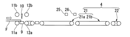
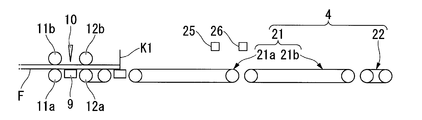
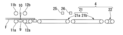
図8A~図8E、図9A~図9E及び図10A~図10Bは、本発明の第2実施形態の搬送装置の動作を示す説明図である。以下、第2実施形態の搬送装置を用いて帯状の偏光フィルムFを切断して搬出するまでの動作を説明する。本実施形態の搬送装置の動作は、第1搬送コンベア21aに載置される枚葉の偏光フィルムFの枚数が1枚である点、第1搬送コンベア21aにおいて偏光フィルムFを加速させるとともに加速後の偏光フィルムFを減速させている点が上記第1実施形態の搬送装置の動作と異なる。
図8A~図8E、図9A~図9E及び図10A~図10Bは、本発明の第2実施形態の搬送装置の動作を示す説明図である。以下、第2実施形態の搬送装置を用いて帯状の偏光フィルムFを切断して搬出するまでの動作を説明する。本実施形態の搬送装置の動作は、第1搬送コンベア21aに載置される枚葉の偏光フィルムFの枚数が1枚である点、第1搬送コンベア21aにおいて偏光フィルムFを加速させるとともに加速後の偏光フィルムFを減速させている点が上記第1実施形態の搬送装置の動作と異なる。
なお、使用する偏光フィルムFの原反ロール7を供給部2に装填してから搬送装置の初期設定を行うまでの工程は上記第1実施形態と同様であるため、詳細な説明を省略する。
供給部2から供給された偏光フィルムFは、切断機構3に搬送される(図8A参照)。偏光フィルムFの先端が把持ローラ12を通過して所定の位置K1に到達すると、制御部6の制御により、昇降ローラ11b,12bが作動する。これにより、偏光フィルムFが吸着テーブル9の両側で把持される。具体的には、両ローラ11b,12bと連結されたエアーシリンダ20が同調し、同時に両ローラ11b,12bを下降させる(図8B参照)。
また、制御部6の制御により、この状態で吸引装置(図示略)を作動させて吸着テーブル9に偏光フィルムFを吸着保持させる。
これらの動作に連動して、制御部6の制御により、ダンサローラDが作動する。
これにより、供給部2から連続的に供給される偏光フィルムFがダンサローラD以降に繰り出さないよう調整される。
これにより、供給部2から連続的に供給される偏光フィルムFがダンサローラD以降に繰り出さないよう調整される。
偏光フィルムFが吸着テーブル9に吸着保持されると、制御部6の制御により、レーザー装置10が作動する(図8C参照)。これにより、吸着テーブル9に吸着保持された偏光フィルムFは、吸着溝14に沿って切断される。その結果、帯状の偏光フィルムFが所定長さの枚葉(1枚)に切断される。
偏光フィルムFが切断されると、偏光フィルムFに対する吸着テーブル9の吸着および把持ローラ11,12による把持とが解除される(図8D参照)。この解除動作と連動して、制御部6の制御により、駆動ローラ11a,12a、第1連続搬送コンベア21(第1搬送コンベア21a、第2搬送コンベア21b)、および第2連続搬送コンベア22が作動する。
切断後の偏光フィルムFは、間欠搬送部3Aを越えて下流側の第1搬送コンベア21a上に載置される(図8E参照)。
偏光フィルムFを第1搬送コンベア21aへ受け渡す動作が完了すると、制御部6の制御により、第1搬送コンベア21aに受け渡された偏光フィルムFは、後端が次にこの第1搬送コンベア21aに受け渡される偏光フィルムFの先端と所定ピッチPだけ離間するように加速される(図9A参照)。
本実施形態においては、第1搬送コンベア21aで偏光フィルムFを加速した後の速度V2aを103.5m/minとし、間欠搬送部3Aで偏光フィルムFを搬送する際の速度V1(90m/min)よりも加速後の偏光フィルムFの速度V2aのほうが大きくなるように制御する(V2a>V1)。
加速された偏光フィルムFは、所定距離だけ第1搬送コンベア21a上を進行する(図9B参照)。その後、制御部6の制御により、偏光フィルムFを第1搬送コンベア21aから第2搬送コンベア21bへ受け渡す際の第1搬送コンベア21aにおける偏光フィルムFの搬送速度が第2搬送コンベア21bにおける偏光フィルムFの搬送速度に近づけられる。具体的には、第1搬送コンベア21aにおいて加速後の偏光フィルムFの先端が所定の位置K3に到達すると、制御部6の制御により、加速後の偏光フィルムFが減速される(図9C参照)。
加速後の偏光フィルムFの先端が所定の位置K3に到達したことは、第1搬送コンベア21aの上方に配置された減速用センサー25により確認される。減速用センサー25が加速後の偏光フィルムFの先端を検知すると、制御部6の制御により、加速後の偏光フィルムFが減速される。
制御部6の制御により、偏光フィルムFを第1搬送コンベア21aから第2搬送コンベア21bに受け渡す際の第1搬送コンベア21aにおける偏光フィルムFの搬送速度と、第2搬送コンベア21bにおける偏光フィルムFの搬送速度とは概ね一致するように制御されることが望ましい。ここで、「概ね一致する」とは、第1搬送コンベア21aにおける減速後の偏光フィルムFの搬送速度V4と第2搬送コンベア21bで偏光フィルムFを搬送する際の速度V5との比V5/V4が0.8/1以上1.2/1以下の範囲である。本実施形態においては、第1搬送コンベア21aで偏光フィルムFを減速した後の速度V4を42m/minとし、第2搬送コンベア21bで偏光フィルムFを搬送する際の速度V5を50m/minとし、搬送速度V4,V5が概ね一致するように制御する。
減速後の偏光フィルムFは、第1搬送コンベア21から第2搬送コンベアへ搬送される(図9D参照)。このとき、減速後の偏光フィルムFの後端が第1搬送コンベア21aを越えたか否かの判定が行われる。例えば、減速後の偏光フィルムFの後端が第1搬送コンベア21aを越えたか否かの判定は、第1搬送コンベア21aの上方に配置された加速用センサー26により行われる。加速用センサー26が減速後の偏光フィルムFの後端を検知すると、制御部6の制御により、第1搬送コンベア21aの搬送速度が切り換えられる。
本実施形態においては、第1搬送コンベア21aの搬送速度は、減速時の42m/minから通常時の90m/minへと切り換えられる。これにより、間欠搬送部3Aから送り出される偏光フィルムFをスムーズに受け取ることが可能となる。
そして、減速後の偏光フィルムFの後端が第1搬送コンベア21aを越えたと判定された場合には、偏光フィルムFを第2搬送コンベア21bへ受け渡す動作が完了する。これにより、減速後の偏光フィルムFは、第1搬送コンベア21aを越えて下流側の第2搬送コンベア21b上に載置される(図9E参照)。
減速後の偏光フィルムFの後端が第1搬送コンベア21aを越えていないと判定された場合には、減速後の偏光フィルムFの後端が第1搬送コンベア21aを越えたと判定されるまで、偏光フィルムFの搬送が継続される。
偏光フィルムFを第2搬送コンベア21bへ受け渡す動作が完了すると、第2搬送コンベア21bに受け渡された偏光フィルムFは、第2連続搬送コンベア22に向けて搬送される(図10A参照)。
制御部6の制御により、偏光フィルムFを第2搬送コンベア21bから第2連続搬送コンベア22へ受け渡す際の第2搬送コンベア21bにおける偏光フィルムFの搬送速度と第2連続搬送コンベア22における偏光フィルムFの搬送速度とが概ね一致するように制御される。
そして、第2連続搬送コンベア22に受け渡された偏光フィルムFは、搬出機構5に向けて搬送される(図10B参照)。
搬出機構5の始端部分にはトレー15が配置されている。したがって、搬送機構4の終端位置から落下してくる偏光フィルムFは、トレー15の内部に逐次収納される。
上記一連の動作を繰り返し、トレー15に所定枚数の偏光フィルムFが積層された後、トレー15を退避位置に退避させる。その後、搬出機構5を作動して積層された偏光フィルムFを次工程に搬出させる。
本実施形態によれば、間欠搬送部3Aで切断された偏光フィルムFの先端部分が第1搬送コンベア21aに接触したまま停止して擦れることを回避することができる。また、切断機構3で切断された偏光フィルムFを第1搬送コンベア21aに送り出す際に、前後の偏光フィルムFが衝突することを回避することができる。さらに、第1搬送コンベア21aで減速された偏光フィルムFの先端部分が第2搬送コンベア21bに接触したまま変速(加速)されて擦れることを回避することができる。したがって、偏光フィルムFの品質の低下を抑制することができる。
また、第1搬送コンベア21aにおいて偏光フィルムFを加速させるとともに、この加速された偏光フィルムFを減速させている。すなわち、偏光フィルムFの搬送速度を可変に制御することを第1搬送コンベア21aのみで行うことができる。よって、偏光フィルムFの搬送速度を可変に制御することを簡単な構成で実現することができる。
以上、添付図面を参照しながら本発明に係る好適な実施の形態例について説明したが、本発明は係る例に限定されないことは言うまでもない。上述した例において示した各構成部材の諸形状や組み合わせ等は一例であって、本発明の主旨から逸脱しない範囲において設計要求等に基づき種々変更可能である。
本発明によれば、光学フィルムの搬送過程において光学フィルムの擦れを回避し、光学フィルムの品質の低下を抑制することが可能な光学フィルムの搬送方法および搬送装置を提供することができる。
1 搬送装置
2 供給部
3 切断機構
3A 間欠搬送部
4 搬送機構
6 制御部
10 レーザー装置(切断部)
21 第1連続搬送コンベア(搬送部)
21a 第1搬送コンベア(搬送部)
21b 第2搬送コンベア(搬送部)
22 第2連続搬送コンベア(搬送部)
V1 光学フィルムを間欠搬送部から第1連続搬送コンベアに受け渡す際の間欠搬送部における光学フィルムの搬送速度
V2 光学フィルムを間欠搬送部から第1連続搬送コンベアに受け渡す際の第1連続搬送コンベアにおける光学フィルムの搬送速度
V2a 偏光フィルムを第1搬送コンベアで加速した後の光学フィルムの搬送速度
V2b 光学フィルムを第1連続搬送コンベアから第2連続搬送コンベアに受け渡す際の第1連続搬送コンベアにおける光学フィルムの搬送速度
V3 光学フィルムを第1連続搬送コンベアから第2連続搬送コンベアに受け渡す際の第2連続搬送コンベアにおける光学フィルムの搬送速度
V4 第1搬送コンベアにおける減速後の偏光フィルムの搬送速度
V5 第2搬送コンベアで偏光フィルムを搬送する際の搬送速度
2 供給部
3 切断機構
3A 間欠搬送部
4 搬送機構
6 制御部
10 レーザー装置(切断部)
21 第1連続搬送コンベア(搬送部)
21a 第1搬送コンベア(搬送部)
21b 第2搬送コンベア(搬送部)
22 第2連続搬送コンベア(搬送部)
V1 光学フィルムを間欠搬送部から第1連続搬送コンベアに受け渡す際の間欠搬送部における光学フィルムの搬送速度
V2 光学フィルムを間欠搬送部から第1連続搬送コンベアに受け渡す際の第1連続搬送コンベアにおける光学フィルムの搬送速度
V2a 偏光フィルムを第1搬送コンベアで加速した後の光学フィルムの搬送速度
V2b 光学フィルムを第1連続搬送コンベアから第2連続搬送コンベアに受け渡す際の第1連続搬送コンベアにおける光学フィルムの搬送速度
V3 光学フィルムを第1連続搬送コンベアから第2連続搬送コンベアに受け渡す際の第2連続搬送コンベアにおける光学フィルムの搬送速度
V4 第1搬送コンベアにおける減速後の偏光フィルムの搬送速度
V5 第2搬送コンベアで偏光フィルムを搬送する際の搬送速度
Claims (10)
- 光学フィルムを搬送する光学フィルムの搬送方法であって、
帯状の光学フィルムを切断部において所定長さの前記光学フィルムに切断する切断工程と;
切断された前記光学フィルムを間欠搬送部により間欠的に搬送する間欠搬送工程と;
前記間欠搬送部から搬送されてきた前記光学フィルムを前記間欠搬送部の下流側に続く複数の搬送部において停止させることなく連続的に搬送する連続搬送工程と;
を含み、
前記間欠搬送部から前記搬送部に前記光学フィルムを受け渡す際に、前記間欠搬送部により前記搬送部に向けて搬送される前記光学フィルムの搬送速度である第1の搬送速度と前記搬送部において搬送される前記光学フィルムの搬送速度である第2の搬送速度とが近付くように、前記第2の搬送速度を可変に制御し;
前記複数の搬送部のうち、上流側搬送部から下流側搬送部に前記光学フィルムを受け渡す際に、前記上流側搬送部から前記下流側搬送部に向けて搬送される前記光学フィルムの搬送速度である第3の搬送速度と前記下流側搬送部上で搬送される前記光学フィルムの搬送速度である第4の搬送速度とが近付くように、前記第3の搬送速度または前記第4の搬送速度を可変に制御する;
ことを特徴とする光学フィルムの搬送方法。 - 前記間欠搬送部から前記搬送部に前記光学フィルムを受け渡す際に、前記間欠搬送部における一の前記間欠搬送工程の終了時点において、前記間欠搬送部から前記光学フィルムの後端が離間するように前記光学フィルムが送り出されることを特徴とする請求項1に記載の光学フィルムの搬送方法。
- 前記間欠搬送部から前記搬送部に前記光学フィルムを受け渡す際に、前記第2の搬送速度の前記第1の搬送速度に対する比を0.8以上1.2以下とすることを特徴とする請求項1または2に記載の光学フィルムの搬送方法。
- 前記上流側搬送部から前記下流側搬送部に前記光学フィルムを受け渡す際に、前記第3の搬送速度の前記第4の搬送速度に対する比を0.8以上1.2以下とすることを特徴とする請求項1または2に記載の光学フィルムの搬送方法。
- 前記間欠搬送部から前記搬送部に前記光学フィルムを受け渡した後、前記光学フィルムの搬送速度が、前記間欠搬送部から前記搬送部に前記光学フィルムが受け渡された際の前記光学フィルムの搬送速度よりも大きくなるように、前記搬送部の搬送速度を大きくすることを特徴とする請求項1または2に記載の光学フィルムの搬送方法。
- 光学フィルムを搬送する光学フィルムの搬送装置であって、
帯状の光学フィルムを供給する供給部と;
前記供給部から供給された帯状の光学フィルムを所定長さの光学フィルムに切断する切断部と;
前記所定長さに切断された前記光学フィルムを間欠的に搬送する間欠搬送部と;
前記間欠搬送部から搬送されてくる前記光学フィルムを受け取りながら停止させることなく連続的に搬送する複数の搬送部と;
前記搬送装置の統括制御を行う制御部と;
を備え、
前記制御部は、前記間欠搬送部からこの間欠搬送部の下流側に続く前記搬送部に前記光学フィルムを受け渡す際に、前記間欠搬送部により前記搬送部に向けて搬送される前記光学フィルムの搬送速度である第1の搬送速度と前記搬送部上で搬送される前記光学フィルムの搬送速度である第2の搬送速度とが近付くように前記第2の搬送速度を可変に制御し、且つ、前記制御部は、前記搬送部のうちの上流側搬送部から下流側搬送部に前記光学フィルムを受け渡す際に、前記上流側搬送部から前記下流側搬送部に向けて搬送される前記光学フィルムの搬送速度である第3の搬送速度と前記下流側搬送部上で搬送される前記光学フィルムの搬送速度である第4の搬送速度とが近付くように前記第3の搬送速度または前記第4の搬送速度を可変に制御する
ことを特徴とする光学フィルムの搬送装置。 - 前記制御部は、前記間欠搬送部から前記搬送部に前記光学フィルムを受け渡す際に、前記間欠搬送部における一の間欠搬送工程の終了時点において、前記間欠搬送部から前記光学フィルムの後端が離間するように前記光学フィルムの送り出しを制御することを特徴とする請求項6に記載の光学フィルムの搬送装置。
- 前記制御部は、前記間欠搬送部から前記搬送部に前記光学フィルムを受け渡す際に、前記第2の搬送速度の前記第1の搬送速度に対する比を0.8以上1.2以下とするように制御することを特徴とする請求項6または7に記載の光学フィルムの搬送装置。
- 前記制御部は、前記上流側搬送部から前記下流側搬送部に前記光学フィルムを受け渡す際に、前記第3の搬送速度の前記第4の搬送速度に対する比を0.8以上1.2以下とするように制御することを特徴とする請求項6または7に記載の光学フィルムの搬送装置。
- 前記制御部は、前記間欠搬送部から前記搬送部に前記光学フィルムを受け渡した後、前記搬送部における前記光学フィルムの搬送速度を、前記間欠搬送部からこの搬送部に前記光学フィルムが受け渡された際の前記光学フィルムの搬送速度よりも大きくなるように制御することを特徴とする請求項6または7に記載の光学フィルムの搬送装置。
Priority Applications (2)
| Application Number | Priority Date | Filing Date | Title |
|---|---|---|---|
| KR1020137030669A KR101932303B1 (ko) | 2011-06-02 | 2012-06-01 | 광학 필름의 반송 방법 및 반송 장치 |
| CN201280025637.5A CN103562104B (zh) | 2011-06-02 | 2012-06-01 | 光学膜的输送方法和输送装置 |
Applications Claiming Priority (2)
| Application Number | Priority Date | Filing Date | Title |
|---|---|---|---|
| JP2011-124264 | 2011-06-02 | ||
| JP2011124264 | 2011-06-02 |
Publications (1)
| Publication Number | Publication Date |
|---|---|
| WO2012165615A1 true WO2012165615A1 (ja) | 2012-12-06 |
Family
ID=47259466
Family Applications (1)
| Application Number | Title | Priority Date | Filing Date |
|---|---|---|---|
| PCT/JP2012/064272 Ceased WO2012165615A1 (ja) | 2011-06-02 | 2012-06-01 | 光学フィルムの搬送方法および搬送装置 |
Country Status (5)
| Country | Link |
|---|---|
| JP (1) | JP5360937B2 (ja) |
| KR (1) | KR101932303B1 (ja) |
| CN (1) | CN103562104B (ja) |
| TW (1) | TWI598281B (ja) |
| WO (1) | WO2012165615A1 (ja) |
Cited By (1)
| Publication number | Priority date | Publication date | Assignee | Title |
|---|---|---|---|---|
| CN111139678A (zh) * | 2018-11-05 | 2020-05-12 | 精工爱普生株式会社 | 薄片制造装置 |
Families Citing this family (7)
| Publication number | Priority date | Publication date | Assignee | Title |
|---|---|---|---|---|
| CN110914180B (zh) * | 2017-06-05 | 2021-07-13 | 富士商工机械株式会社 | 幅材贴合装置 |
| TWI646133B (zh) * | 2017-08-22 | 2019-01-01 | 住華科技股份有限公司 | 輸送系統 |
| JP6898488B1 (ja) * | 2020-03-18 | 2021-07-07 | 日東電工株式会社 | 光学積層体の搬送装置及び搬送方法 |
| CN115285773B (zh) * | 2022-09-30 | 2022-12-06 | 常州市武进天龙发展有限公司 | 光学膜片输送设备 |
| CN115534001B (zh) * | 2022-12-01 | 2023-03-17 | 苏州天立达精密科技股份有限公司 | 一种复合胶带加工用模切设备的上料装置 |
| JP7815173B2 (ja) * | 2023-05-30 | 2026-02-17 | 日東電工株式会社 | 光学フィルム片の製造方法および光学フィルムの切断方法 |
| CN117306057A (zh) * | 2023-09-27 | 2023-12-29 | 福建锦程高科实业有限公司 | 一种锦纶丝加弹机的热箱装置 |
Citations (3)
| Publication number | Priority date | Publication date | Assignee | Title |
|---|---|---|---|---|
| JPS57184038A (en) * | 1981-05-08 | 1982-11-12 | Will E C H Gmbh & Co | Conveyor for sheet layer |
| JP2005141259A (ja) * | 2005-02-07 | 2005-06-02 | Fuji Xerox Co Ltd | 画像形成装置 |
| JP2007533567A (ja) * | 2003-10-29 | 2007-11-22 | シーメンス アクチエンゲゼルシヤフト | オーバラップした扁平な発送物を個別化するための装置 |
Family Cites Families (5)
| Publication number | Priority date | Publication date | Assignee | Title |
|---|---|---|---|---|
| JPS5986545A (ja) * | 1982-11-11 | 1984-05-18 | Taiyo Shokai:Kk | シ−ト状物送り出し装置 |
| JP2008200788A (ja) * | 2007-02-19 | 2008-09-04 | Sumitomo Chemical Co Ltd | 光学フィルムの裁断装置および光学フィルムの製造方法 |
| CN201043102Y (zh) * | 2007-06-08 | 2008-04-02 | 天津华一有限责任公司 | 卷膜切割机构 |
| KR101385790B1 (ko) * | 2008-08-19 | 2014-04-16 | 아께보노 기까이 고오교오 가부시끼가이샤 | 광학 필름의 반송 방법 및 이를 이용한 장치 |
| JP5214514B2 (ja) * | 2009-03-26 | 2013-06-19 | セイコーエプソン株式会社 | 搬送装置及び流体噴射装置 |
-
2012
- 2012-06-01 TW TW101119706A patent/TWI598281B/zh not_active IP Right Cessation
- 2012-06-01 JP JP2012125915A patent/JP5360937B2/ja not_active Expired - Fee Related
- 2012-06-01 CN CN201280025637.5A patent/CN103562104B/zh not_active Expired - Fee Related
- 2012-06-01 WO PCT/JP2012/064272 patent/WO2012165615A1/ja not_active Ceased
- 2012-06-01 KR KR1020137030669A patent/KR101932303B1/ko not_active Expired - Fee Related
Patent Citations (3)
| Publication number | Priority date | Publication date | Assignee | Title |
|---|---|---|---|---|
| JPS57184038A (en) * | 1981-05-08 | 1982-11-12 | Will E C H Gmbh & Co | Conveyor for sheet layer |
| JP2007533567A (ja) * | 2003-10-29 | 2007-11-22 | シーメンス アクチエンゲゼルシヤフト | オーバラップした扁平な発送物を個別化するための装置 |
| JP2005141259A (ja) * | 2005-02-07 | 2005-06-02 | Fuji Xerox Co Ltd | 画像形成装置 |
Cited By (2)
| Publication number | Priority date | Publication date | Assignee | Title |
|---|---|---|---|---|
| CN111139678A (zh) * | 2018-11-05 | 2020-05-12 | 精工爱普生株式会社 | 薄片制造装置 |
| CN111139678B (zh) * | 2018-11-05 | 2022-05-17 | 精工爱普生株式会社 | 薄片制造装置 |
Also Published As
| Publication number | Publication date |
|---|---|
| JP2013010635A (ja) | 2013-01-17 |
| KR20140030200A (ko) | 2014-03-11 |
| TW201309581A (zh) | 2013-03-01 |
| CN103562104B (zh) | 2015-11-25 |
| TWI598281B (zh) | 2017-09-11 |
| CN103562104A (zh) | 2014-02-05 |
| KR101932303B1 (ko) | 2018-12-24 |
| JP5360937B2 (ja) | 2013-12-04 |
Similar Documents
| Publication | Publication Date | Title |
|---|---|---|
| JP5360937B2 (ja) | 光学フィルムの搬送方法および搬送装置 | |
| JP5002018B2 (ja) | 光学フィルムの搬送方法およびこれを用いた装置 | |
| JP6427952B2 (ja) | 搬送装置 | |
| WO2010021024A1 (ja) | 光学フィルムの切断方法およびこれを用いた装置 | |
| JP5963073B2 (ja) | 光学フィルムの切断方法および切断装置 | |
| TWI889071B (zh) | 片材分離裝置及片材分離方法 | |
| CN103449237B (zh) | 裁纸装置、后处理装置及图像形成系统 | |
| JP2014024660A (ja) | シート材積層装置 | |
| KR101989409B1 (ko) | 시트 박리 방법 및 시트 박리 장치 | |
| JP5986556B2 (ja) | シート巻取装置 | |
| CN103466356B (zh) | 搬纸装置、后处理装置及图像形成系统 | |
| JP2019116346A (ja) | 媒体給送装置及び画像読取装置 | |
| JP2020045201A (ja) | 媒体排出装置、媒体処理装置、及び記録システム | |
| JP2006248704A (ja) | 給紙装置の制御装置 | |
| JP5985303B2 (ja) | シートの搬送方向転換装置 | |
| JP2007130707A (ja) | 紙切断搬送装置及び紙切断搬送方法 | |
| JP2010100413A (ja) | 印刷機の排紙装置及びその運転方法 | |
| JP2007297144A (ja) | シート状ゴム材料の供給装置 | |
| JP2018030673A (ja) | 枚葉媒体収納装置 | |
| JP2017137177A (ja) | 物品積層装置 | |
| WO2015173952A1 (ja) | 製品搬送装置 |
Legal Events
| Date | Code | Title | Description |
|---|---|---|---|
| 121 | Ep: the epo has been informed by wipo that ep was designated in this application |
Ref document number: 12792184 Country of ref document: EP Kind code of ref document: A1 |
|
| ENP | Entry into the national phase |
Ref document number: 20137030669 Country of ref document: KR Kind code of ref document: A |
|
| NENP | Non-entry into the national phase |
Ref country code: DE |
|
| 122 | Ep: pct application non-entry in european phase |
Ref document number: 12792184 Country of ref document: EP Kind code of ref document: A1 |