WO2012165193A1 - Particules de prévention de contrefaçon et procédé pour leur fabrication, encre de prévention de contrefaçon, feuille de prévention de contrefaçon, certificat de valeurs financières, cartes - Google Patents
Particules de prévention de contrefaçon et procédé pour leur fabrication, encre de prévention de contrefaçon, feuille de prévention de contrefaçon, certificat de valeurs financières, cartes Download PDFInfo
- Publication number
- WO2012165193A1 WO2012165193A1 PCT/JP2012/062923 JP2012062923W WO2012165193A1 WO 2012165193 A1 WO2012165193 A1 WO 2012165193A1 JP 2012062923 W JP2012062923 W JP 2012062923W WO 2012165193 A1 WO2012165193 A1 WO 2012165193A1
- Authority
- WO
- WIPO (PCT)
- Prior art keywords
- layer
- metal layer
- particles
- resin layer
- water
- Prior art date
Links
Images


Classifications
-
- B—PERFORMING OPERATIONS; TRANSPORTING
- B42—BOOKBINDING; ALBUMS; FILES; SPECIAL PRINTED MATTER
- B42D—BOOKS; BOOK COVERS; LOOSE LEAVES; PRINTED MATTER CHARACTERISED BY IDENTIFICATION OR SECURITY FEATURES; PRINTED MATTER OF SPECIAL FORMAT OR STYLE NOT OTHERWISE PROVIDED FOR; DEVICES FOR USE THEREWITH AND NOT OTHERWISE PROVIDED FOR; MOVABLE-STRIP WRITING OR READING APPARATUS
- B42D25/00—Information-bearing cards or sheet-like structures characterised by identification or security features; Manufacture thereof
- B42D25/30—Identification or security features, e.g. for preventing forgery
- B42D25/36—Identification or security features, e.g. for preventing forgery comprising special materials
- B42D25/378—Special inks
-
- B—PERFORMING OPERATIONS; TRANSPORTING
- B41—PRINTING; LINING MACHINES; TYPEWRITERS; STAMPS
- B41M—PRINTING, DUPLICATING, MARKING, OR COPYING PROCESSES; COLOUR PRINTING
- B41M3/00—Printing processes to produce particular kinds of printed work, e.g. patterns
- B41M3/14—Security printing
-
- B—PERFORMING OPERATIONS; TRANSPORTING
- B42—BOOKBINDING; ALBUMS; FILES; SPECIAL PRINTED MATTER
- B42D—BOOKS; BOOK COVERS; LOOSE LEAVES; PRINTED MATTER CHARACTERISED BY IDENTIFICATION OR SECURITY FEATURES; PRINTED MATTER OF SPECIAL FORMAT OR STYLE NOT OTHERWISE PROVIDED FOR; DEVICES FOR USE THEREWITH AND NOT OTHERWISE PROVIDED FOR; MOVABLE-STRIP WRITING OR READING APPARATUS
- B42D25/00—Information-bearing cards or sheet-like structures characterised by identification or security features; Manufacture thereof
- B42D25/20—Information-bearing cards or sheet-like structures characterised by identification or security features; Manufacture thereof characterised by a particular use or purpose
- B42D25/29—Securities; Bank notes
-
- B—PERFORMING OPERATIONS; TRANSPORTING
- B42—BOOKBINDING; ALBUMS; FILES; SPECIAL PRINTED MATTER
- B42D—BOOKS; BOOK COVERS; LOOSE LEAVES; PRINTED MATTER CHARACTERISED BY IDENTIFICATION OR SECURITY FEATURES; PRINTED MATTER OF SPECIAL FORMAT OR STYLE NOT OTHERWISE PROVIDED FOR; DEVICES FOR USE THEREWITH AND NOT OTHERWISE PROVIDED FOR; MOVABLE-STRIP WRITING OR READING APPARATUS
- B42D25/00—Information-bearing cards or sheet-like structures characterised by identification or security features; Manufacture thereof
- B42D25/40—Manufacture
- B42D25/405—Marking
- B42D25/43—Marking by removal of material
-
- C—CHEMISTRY; METALLURGY
- C09—DYES; PAINTS; POLISHES; NATURAL RESINS; ADHESIVES; COMPOSITIONS NOT OTHERWISE PROVIDED FOR; APPLICATIONS OF MATERIALS NOT OTHERWISE PROVIDED FOR
- C09D—COATING COMPOSITIONS, e.g. PAINTS, VARNISHES OR LACQUERS; FILLING PASTES; CHEMICAL PAINT OR INK REMOVERS; INKS; CORRECTING FLUIDS; WOODSTAINS; PASTES OR SOLIDS FOR COLOURING OR PRINTING; USE OF MATERIALS THEREFOR
- C09D11/00—Inks
- C09D11/02—Printing inks
- C09D11/10—Printing inks based on artificial resins
- C09D11/101—Inks specially adapted for printing processes involving curing by wave energy or particle radiation, e.g. with UV-curing following the printing
-
- B42D2033/20—
-
- B—PERFORMING OPERATIONS; TRANSPORTING
- B42—BOOKBINDING; ALBUMS; FILES; SPECIAL PRINTED MATTER
- B42D—BOOKS; BOOK COVERS; LOOSE LEAVES; PRINTED MATTER CHARACTERISED BY IDENTIFICATION OR SECURITY FEATURES; PRINTED MATTER OF SPECIAL FORMAT OR STYLE NOT OTHERWISE PROVIDED FOR; DEVICES FOR USE THEREWITH AND NOT OTHERWISE PROVIDED FOR; MOVABLE-STRIP WRITING OR READING APPARATUS
- B42D25/00—Information-bearing cards or sheet-like structures characterised by identification or security features; Manufacture thereof
- B42D25/30—Identification or security features, e.g. for preventing forgery
- B42D25/328—Diffraction gratings; Holograms
Definitions
- the present invention includes credit cards, cash cards, ID cards, membership cards and other cards, banknotes, stock certificates, gift certificates, lottery tickets, bills, checks, admission tickets, and other securities, cash certificates, various certificates, and high-priced products. It relates to anti-counterfeit particles used as so-called taggants.
- taggant also referred to as taggent
- taggant an anti-counterfeit additive
- the taggant is required to be highly difficult to counterfeit, to be able to easily and quickly perform authenticity determination, and to be inexpensive.
- micro marker that is configured to be observable using an optical magnifying device and patterned is disclosed.
- These micro-markers are formed by lithographic techniques in the integrated circuit technology field, or formed by other micro-machining technology field methods, such as graphics, logos, personal It is configured to be recognized as having information based on the contents of the design, such as a signature, date, and words (see Patent Document 1).
- taggant particles are generally made of resin, have low mechanical strength, and have a problem of low durability that they are damaged when applied to an article and cannot be identified.
- the taggant particles made of resin have a problem of low designability in applications that require metallic luster.
- the present invention has been made in view of the above-described problems, and an object thereof is to obtain anti-counterfeit particles having high durability and excellent design, which are used as taggant particles.
- Anti-counterfeit particles characterized in that at least a resin layer and a metal layer are laminated, and the shape can be identified by observing it in an enlarged manner.
- the shape of the particle is a flat plate shape, and the shape of the particle and / or the shape of the penetrating portion is any one or more of letters, numbers, symbols, and figures ( Anti-counterfeit particles according to 1).
- the uneven shape is a diffraction grating or a hologram, and any one or more of letters, numbers, symbols, and figures are displayed on the surface of the anti-counterfeit particles by the diffraction grating or the hologram.
- a counterfeit characterized in that particles, which are formed by laminating at least a resin layer and a metal layer, and are identifiable by observing an enlarged shape, are dispersed in a dispersion medium. Ink for prevention.
- Anti-counterfeiting characterized in that particles are characterized in that at least a resin layer and a metal layer are laminated and the shape is identifiable by being observed in an enlarged manner, and particles are dispersed in the resin. Sheet.
- a securities characterized in that at least a resin layer and a metal layer are laminated, and particles are characterized by being identifiable by observing an enlarged shape. .
- a card characterized in that at least a resin layer and a metal layer are laminated, and particles characterized by being observable in an enlarged shape are provided on the surface.
- An exposure step of exposing to a pattern having an identifiable shape a patterning step of developing with an alkaline developer and patterning the photosensitive resin layer and the alkali-soluble metal layer, dissolving the sacrificial layer,
- a method for producing anti-counterfeit particles comprising: a peeling step of peeling a particle obtained by laminating a photosensitive resin layer and the alkali-soluble metal layer from the substrate.
- a water-soluble ink layer forming step for forming a water-soluble ink layer on a substrate, a concavo-convex shape forming step for forming a concavo-convex shape on the surface of the water-soluble ink layer, the substrate and the water-soluble A metal layer forming step of forming a metal layer on the ink layer; a resin layer forming step of forming a resin layer in the same pattern as the water-soluble ink layer on the metal layer; and immersing the substrate in water.
- a method for producing anti-counterfeit particles comprising: a peeling step of peeling off the particles obtained by laminating the resin layer and the metal layer from the substrate.
- anti-counterfeit particles having high durability and excellent design can be obtained which are used as taggant particles.
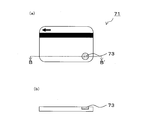
- FIG. 4A is a plan view showing a card 71
- FIG. 4B is a cross-sectional view showing a B-B ′ section in FIG.
- A)-(d) The schematic sectional drawing explaining the 1st manufacturing method of the particle
- A)-(d) The schematic sectional drawing explaining the 2nd manufacturing method of the particle
- (A), (b) The perspective view which shows particle
- (A)-(e) The schematic sectional drawing explaining the 1st manufacturing method of particle
- (A)-(g) The schematic sectional drawing explaining the 2nd manufacturing method of particle
- FIG. 1 is a view showing a particle 1 according to the first embodiment.
- the particle 1 shown in FIG. 1 is formed by laminating a metal layer 3 and a resin layer 5 and has a substantially flat plate shape, but can be identified by observing the outline and the shape of the penetrating portion 7 in an enlarged manner. That is, it can be identified by magnifying and observing the outline of the base body and the penetrating portion provided in the base body.
- the letter “DNP” consisting of the penetrating portion 7 is formed on the disc-shaped base, but the outline of the base is not limited to the disc, but an ellipse, polygon, heart, star Various shapes such as molds, animal contours, character contours, number contours, symbol contours, figure contours, etc. can be employed. Further, as the shape of the penetrating portion 7, various numbers, symbols, figures, etc. can be applied in addition to characters. In FIG. 1, the penetrating part 7 is provided, but the penetrating part 7 is not essential when the particle outline is observed by being enlarged and can be identified.
- the shape is identifiable means that an artificial shape is formed and can be distinguished from a shape that is naturally formed without intention. Therefore, in the case of forging an article to which particles 1 are applied, even if the outer shape of the article can be copied, it is difficult to copy the particles 1, so that it is possible to discriminate between a genuine article and a forged article. In addition, since the shape can be identified, it is possible to discriminate the production time, the use, and the like even between genuine articles by changing the shape of the particles 1 to be applied.
- the metal constituting the metal layer 3 is not particularly limited, but nickel and aluminum are preferable from the standpoint of availability, ease of film formation, resistance to oxidation in the atmosphere, and cost of raw materials.
- the thickness of the metal layer 3 is not particularly limited, but is preferably about 1 to 250 nm, and more preferably about 10 to 100 nm.
- the resin constituting the resin layer 5 is not particularly limited, but a resist material such as a color resist or DFR (dry film resist), a pigment, a dye offset ink, or a silk screen ink is preferable from the viewpoint of design and durability. .
- a resist material such as a color resist or DFR (dry film resist), a pigment, a dye offset ink, or a silk screen ink is preferable from the viewpoint of design and durability.
- the offset ink or silk screen ink is oily.
- the resin layer 5 contains a pigment for coloring, colored particles 1 can be obtained, and the design and anti-counterfeiting effect are improved.
- the thickness of the particle 1 is preferably 1 ⁇ m or more, and preferably 25 ⁇ m or less. If the thickness is too thin, the strength cannot be maintained, and the particles are easily damaged during handling. On the other hand, if the thickness is too thick, it becomes difficult to form a thick film of the photosensitive resin during production, and the dispersibility in the resin or the dispersion medium is poor, which is inconvenient to handle.
- the size of the particles 1 is preferably 10 to 300 ⁇ m. If it is too small, particles cannot be observed using a simple magnifying device such as a magnifying glass, and authentication cannot be performed unless a more complicated device such as a microscope is used. On the other hand, if the size is too large, the characteristics of the particles can be recognized with the naked eye without using a magnifying device, and the effect of preventing forgery is reduced. In addition, since the particle
- the size is the longest length when the particle is viewed in plan, for example, the length of the diagonal line if the shape is a quadrangle, and the length of the long axis if the shape is an ellipse. is there. Further, the character “DNP” in FIG. 1 is not large enough to be recognized with the naked eye, but is large enough to be recognized using a loupe or the like.
- the particle 1 according to the first embodiment includes a metal layer, it has excellent mechanical strength, excellent durability, metallic luster, and excellent design.
- the particle 1 according to the first embodiment cannot grasp the characteristics of the particle 1 with the naked eye and can grasp the characteristics for the first time with an apparatus such as a loupe, it is easy for the imparted article to be provided with anti-counterfeiting technology. I do n’t know. Therefore, the particle
- grains 1 can exhibit the higher forgery prevention effect compared with the forgery prevention technique which can be confirmed visually.
- the anti-counterfeit sheet is obtained by dispersing the particles 1 according to the first embodiment in an ultraviolet curable resin or the like and drying or curing.
- an ultraviolet curable resin or the like for example, by applying a transparent ultraviolet curable resin in which particles are dispersed onto an article, irradiating with ultraviolet rays and curing the article, a sheet provided with particles can be formed on the article.
- the particles 1 are placed in an extrusion molding machine or an injection molding machine using polyvinyl chloride (PVC), polypropylene (PP), acrylonitrile-butadiene-styrene copolymer resin (ABS), acrylonitrile-ethylene-styrene copolymer resin (AES).
- PVC polyvinyl chloride
- PP polypropylene
- ABS acrylonitrile-butadiene-styrene copolymer resin
- AES acrylonitrile-ethylene-styrene copolymer resin
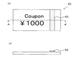
- the securities 61 have a band-shaped particle containing portion 63.
- the particle-containing part 63 is obtained by printing ink containing particles in a band shape, or by pasting or forming a belt-like sheet containing particles.
- the card 71 has a circular particle-containing portion 73.
- the particle-containing portion 73 is obtained by printing ink containing particles in a circular shape, or by pasting or forming a circular sheet containing particles.
- grain containing part 73 is formed in the recessed part of the card
- securities include banknotes, stock certificates, gift certificates, lottery tickets, bills, checks, admission tickets, and cards include credit cards, cash cards, ID cards, and membership cards.
- grain containing parts 63 and 73 is not restricted to strip
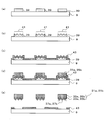
- FIG. 4A shows a water-soluble ink layer forming step.
- the water-soluble ink layer forming step is a step of forming the water-soluble ink layer 11 on the base material 9 with a pattern having a shape that can be identified by being enlarged and observed.
- FIG. 4B shows a metal layer forming process.
- the metal layer forming step is a step of forming the metal layer 3 on the entire surface on the base material 9 and the water-soluble ink layer 11.
- FIG. 4C shows a resin layer forming step.
- the resin layer forming step is a step of forming the resin layer 5 on the metal layer 3 with the same pattern as the water-soluble ink layer 11.
- FIG. 4D shows the peeling process.
- the peeling step is a step in which the base material 9 is immersed in water and the particles 1 in which the resin layer 5 and the metal layer 3 are laminated are peeled off from the base material 9.
- a water-soluble ink layer 11 is formed on a substrate 9 by printing.
- the water-soluble ink is a printing ink using alcohol and water as solvents, and is not particularly limited as long as it is an ink such as offset, gravure, letterpress, silk screen printing.
- the water-soluble ink layer 11 is formed by printing water-soluble ink in a pattern corresponding to the shape of the particles 1.
- the substrate 9 is not particularly limited, and a substrate generally used for photolithography can be used.
- non-flexible transparent rigid materials such as borosilicate glass, aluminoborosilicate glass, alkali-free glass, quartz glass, synthetic quartz glass, soda lime glass, white sapphire, transparent resin film, optical resin film
- a transparent flexible material having flexibility such as can be used.
- acrylic such as polymethyl methacrylate, polyamide, polyacetal, polybutylene terephthalate, polyethylene terephthalate, polyethylene naphthalate, triacetyl cellulose, syndiotactic polystyrene, polyphenylene sulfide, polyether ketone, polyether ether ketone, Fluorine resin, polyether nitrile, polycarbonate, modified polyphenylene ether, polycyclohexene, polynorbornene resin, polysulfone, polyethersulfone, polyarylate, polyamideimide, polyetherimide, thermoplastic polyimide, etc. can be mentioned. However, those made of general plastics can also be used.
- the metal layer 3 is formed on the entire surface of the substrate 9 and the water-soluble ink layer 11.
- the metal used for the metal layer 3 is not particularly limited as long as it is a water-resistant metal that does not cause a problem when immersed in water in a later step.
- the film-forming method of the metal layer 3 can use well-known film-forming methods, such as electroplating, sputtering, and vacuum evaporation. Among these, from the viewpoint of ease of film formation and cost, electroplating (electroforming) is preferable as a method for forming the metal layer 3.
- the metal layer 3 may be composed of a plurality of metal layers. Moreover, when performing electroplating, it is preferable to form a seed layer by performing electroless plating or sputtering on the surface of the substrate 9 and the water-soluble ink layer 11.
- the resin layer 5 is formed on the metal layer 3 in the same pattern as the water-soluble ink layer 11.
- the formation method of the resin layer 5 is not particularly limited, but is preferably formed by silk screen printing of water-resistant ink.
- Water-resistant ink is printing using organic solvents such as toluene, xylene, ethyl acetate, n-propyl acetate, methyl ethyl ketone (MEK), methyl isobutyl ketone (MIBK), isopropyl alcohol (IPA), ethanol, and n-propanol. Ink.
- the base material 9 is immersed in water, the water-soluble ink layer 11 is dissolved, and the metal layer 3 and the resin layer 5 formed on the water-soluble ink layer 11 are dissolved. Then, the particles 1 are peeled off from the base material 9.
- the penetrating portion 7 is not shown in the particle 1, but the penetrating portion 7 can be obtained by patterning the water-soluble ink layer 11 and the resin layer 5 in a predetermined pattern.
- the particles 1 in which the metal layer 3 and the resin layer 5 are laminated can be obtained by the production method of the present invention.
- the metal foil patterning method using water-soluble ink which has been widely used in the past, is used, it is not necessary to introduce new equipment, and the particles 1 are manufactured at low cost. can do.
- the metal foil patterning method using water-soluble ink is a technique in which the metal layer that is peeled off when immersed in water is an unnecessary part and the metal layer is left in a predetermined pattern on the printed material.
- the metal layer to be peeled is used as a metal layer constituting the particle 1.
- a plurality of particles 1 can be formed on a single substrate 9, and a large amount of particles 1 can be manufactured.
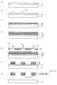
- FIG. 5A shows the base material preparation step.
- a base material preparation process shows the process of preparing the base material with which the sacrificial layer 13, the alkali-soluble metal layer 15, and the photosensitive resin layer 17 were laminated
- FIG. 5B shows an exposure process.
- the exposure step is a step of exposing the photosensitive resin layer 17 on the base material 9 to a pattern having a shape that can be identified by magnifying and observing.
- FIG. 5C shows a patterning process.
- the patterning step is a step of patterning the photosensitive resin layer 17 and the alkali-soluble metal layer 15 by developing with an alkaline developer.
- FIG. 5D shows the peeling process.
- the peeling process is a process in which the sacrificial layer 13 is melted and the particles 1 in which the photosensitive resin layer 17 and the alkali-soluble metal layer 15 are laminated are peeled from the substrate 9.
- a sacrificial layer 13, an alkali-soluble metal layer 15, and a photosensitive resin layer 17 are formed on a substrate 9.
- the water-soluble resin used for the sacrificial layer 13 polyvinyl alcohol, polyethylene oxide, gelatin or the like is used.
- the sacrificial layer 13 serves to hold the particles on the substrate until they are separated into individual pieces.
- the sacrificial layer is a layer formed on the assumption that it is finally removed, and is often used when a film is partially formed or two films are separated.
- DFR or the like that dissolves in an organic solvent such as acetone may be used as the sacrificial layer 13 instead of the water-soluble resin, and the sacrificial layer 13 may be dissolved using an organic solvent when the particles 1 described later are peeled off.
- the sacrificial layer 13 is not limited to the water-soluble resin, but may be any solvent that does not affect the material forming the particles.
- the alkali-soluble metal used for the alkali-soluble metal layer at least one alkali-soluble metal selected from the group consisting of aluminum, zinc, silicon, lead, and tin can be used. It is preferable to use aluminum.
- a known film forming method such as sputtering or vacuum deposition can be used.
- the thickness of the alkali-soluble metal layer 15 is not particularly limited, but is usually about 1 to 250 nm and about 10 to 100 nm in order to satisfy the ease of film formation, low cost, and certainty of peeling. Is more common.
- the photosensitive resin layer 17 is obtained by applying a positive or negative photosensitive resin composition over the entire surface.
- the negative photosensitive resin is not particularly limited, and a commonly used negative photosensitive resin can be used.
- a chemically amplified photosensitive resin based on a crosslinked resin specifically, a chemically amplified photosensitive resin in which a crosslinking agent is added to polyvinylphenol and an acid generator is further added.
- an acrylic negative photosensitive resin a photopolymerization initiator that generates a radical component upon irradiation with ultraviolet rays, a component that has an acrylic group in the molecule, causes a polymerization reaction by the generated radical, and cures thereafter
- a functional group that can dissolve an unexposed portion by development for example, a component containing an acidic group component in the case of development with an alkaline solution can be used.
- relatively low molecular weight polyfunctional acrylic molecules include dipentaerythritol hexaacrylate (DPHA), dipentaerythritol pentaacrylate (DPPA), tetramethylpentatriacrylate (TMPTA) and the like.
- DPHA dipentaerythritol hexaacrylate
- DPPA dipentaerythritol pentaacrylate
- TMPTA tetramethylpentatriacrylate
- High molecular weight polyfunctional acrylic molecules include polymers in which an acrylic group is introduced via an epoxy group into a part of the carboxylic acid group of the styrene-acrylic acid-benzyl methacrylate copolymer, and methyl methacrylate-styrene- An acrylic acid copolymer etc. are mentioned.
- the positive photosensitive resin is not particularly limited, and a commonly used one can be used. Specifically, a chemically amplified photosensitive resin using a novolac resin as
- the photosensitive resin layer 17 may be formed by attaching a dry film resist (DFR).
- DFR dry film resist
- FIG. 5B shows the photosensitive resin layer 17 in a predetermined pattern through a mask 21 having a predetermined pattern.
- the mask 21 is provided with a light shielding film 25 on a transparent substrate 23, and a transmission part through which the exposure light 19 is transmitted and a light shielding part through which the exposure light 19 is not substantially transmitted are formed by the light shielding film.
- FIG. 5B shows the case where a negative photosensitive resin composition is used for the photosensitive resin layer 17.
- the step of exposing the photosensitive resin layer 17 in a predetermined pattern is not particularly limited, but other than the method of using a mask as shown in FIG. 5B, a digital micromirror device is used without passing through the mask. You may expose to.
- a digital micromirror device also called a digital mirror device or DMD
- DMD digital mirror device
- a digital micromirror device is an element in which a number of micromirror surfaces (micromirrors) that can be individually driven are arranged in a plane. By individually driving each mirror, light projection can be controlled for each display pixel, so that exposure can be performed in a predetermined pattern without using a mask.
- exposure can be performed with a predetermined pattern by direct drawing with a laser or an electron beam.
- the photosensitive resin layer 17 is dissolved with an alkaline developer, and the underlying alkali-soluble metal layer 15 is dissolved.
- the photosensitive resin layer 17 and the alkali-soluble metal layer are then dissolved. 15 is patterned.
- the base material 9 is immersed in water, the sacrificial layer 13 is dissolved, and the alkali-soluble metal layer 15 and the photosensitive resin layer 17 formed on the sacrificial layer 13
- the particles 1 having the detachment from the substrate 9 are obtained.
- the alkali-soluble metal layer 15 and the photosensitive resin layer 17 correspond to the metal layer 3 and the resin layer 5 constituting the particles 1.
- the particles 1 in which the metal layer 3 and the resin layer 5 are laminated can be obtained by the production method of the present invention.
- a plurality of particles 1 can be formed on a single substrate 9, and a large amount of particles 1 can be manufactured.
- FIGS. 6A and 6B are views showing particles 31a and 31b according to the second embodiment of the present invention.
- the particles 31a shown in FIG. 6 (a) display characters in a concavo-convex shape that can be identified by magnifying and observing on a substantially flat substrate formed by laminating a metal layer 33a and a resin layer 35a.
- a diffraction grating or hologram identification portion 37a is formed on the metal layer 33a.
- the diffraction grating or hologram of the identification unit 37a reproduces a three-dimensional image by recording light interference fringes on a substrate with a fine unevenness process having a depth of 1 ⁇ m or less.
- the base of the particle 31a can be identified by magnifying and observing, and the shape is not limited to a disc, and various shapes such as an ellipse, a polygon, and a star can be used.
- the identification unit 37a provided on the base can be provided with various figures, numbers, symbols, flowers, designs, and the like. That is, identification is possible by magnifying and observing the identification part 37a made of a design such as the outline of the substrate and the shape, pattern or color applied to the substrate.
- a metal or a resin constituting the metal layer 3 and the resin layer 5 according to the first embodiment can be used, respectively.
- the thickness of the particles 31a is preferably 1 ⁇ m or more and 25 ⁇ m or less. If the thickness is too thin, the strength cannot be maintained, and the particles are damaged during handling. On the other hand, if the thickness is too thick, it becomes difficult to form a thick metal film during production, and the dispersibility in a resin or dispersion medium is poor, which is inconvenient in handling.
- the size of the particles 31a is preferably 10 to 300 ⁇ m. If it is too small, particles 31a cannot be observed using a simple magnifying instrument such as a magnifying glass, and authenticity cannot be determined unless a more complicated device such as a microscope is used. On the other hand, if the size is too large, it becomes possible to recognize the characteristics of the particles 31a with the naked eye without using a magnifying device, and the effect of preventing forgery is reduced. In addition, since the particle
- the size is the longest length when the particle is viewed in plan, for example, the length of the diagonal line if the shape is a quadrangle, and the length of the long axis if the shape is an ellipse. is there.
- the character “DNP” in FIG. 6A cannot be recognized with the naked eye, but is large enough to be recognized using a loupe or the like.
- the particles 31a according to the second embodiment include a metal layer, they have excellent mechanical strength, excellent durability, metallic luster, and excellent design.
- the particle 31a according to the second embodiment has a concavo-convex shape such as a hologram or a diffraction grating that is difficult to manufacture on the surface, the particle 31a is excellent in an anti-counterfeit effect.
- the particles 31a according to the second embodiment are applied to an article, the characteristics of the particles cannot be grasped with the naked eye, and it cannot be confirmed that the anti-counterfeiting technology is applied. A higher anti-counterfeit effect can be exhibited.
- the application of the particles 31a according to the second embodiment is the same as that of the particles 1 according to the first embodiment.
- the particles 31b shown in FIG. 6 (b) are three-dimensional characters as concavo-convex shapes that can be identified by magnifying and observing them on a substantially flat substrate formed by laminating a metal layer 33b and a resin layer 35b.
- the identification part 37b is formed on the metal layer 33b.
- a thick character is formed on a disk-shaped substrate, but the shape of the substrate is not limited to a disk, and various shapes such as an ellipse, a polygon, and a star are used. Can be used.
- a three-dimensional flower or design can be applied.
- the depth is 1 ⁇ m or more.
- the configuration of the particle 31b is the same as that of the particle 31a except that the identification unit 37b is different.
- the thickness of the particle 31b is preferably 2 ⁇ m or more, and preferably 25 ⁇ m or less. If the thickness is too thin, the strength cannot be maintained, the particles are easily damaged during handling, and the three-dimensional structure formed in the particles is not observed three-dimensionally. On the other hand, if the thickness is too thick, it becomes difficult to form a thick metal film during production, and the dispersibility in a resin or dispersion medium is poor, which is inconvenient in handling.
- the particle 31b according to the second embodiment includes a metal layer, the particle 31b has excellent mechanical strength, excellent durability, metallic luster, and excellent design.
- the particles 31b according to the second embodiment have uneven shapes such as three-dimensional characters that are difficult to manufacture on the surface, the particles 31b are excellent in the forgery prevention effect.
- the particles 31b according to the second embodiment are applied to an article, the characteristics of the particles cannot be grasped with the naked eye, and it cannot be confirmed that the anti-counterfeiting technology is applied. A higher anti-counterfeit effect can be exhibited.
- the application of the particles 31b according to the second embodiment is the same as that of the particles 1 according to the first embodiment.
- the particle 31a having the diffraction grating or hologram identification portion 37a and the particle 31b having the three-dimensional identification portion 37b can be manufactured by the same manufacturing method except that the shape of the concavo-convex shape 41 or 47 is different.
- the uneven shapes 41 and 47 are shapes that serve as templates corresponding to the shape of the identification portion 37a or 37b, but are simplified in FIGS.
- the concave / convex shapes 41 and 47 having a fine concave / convex mold in which light interference fringes are recorded on the surface or a reverse shape are formed.
- FIG. 7A shows a water-soluble ink layer forming step.
- the water-soluble ink layer forming step is a step of forming the water-soluble ink layer 39 on the substrate 9.
- FIG.7 (b) shows an uneven
- the uneven shape forming step is a step of forming the uneven shape 41 on the surface of the water-soluble ink layer 39.
- FIG.7 (c) shows a metal layer formation process.
- the metal layer forming step is a step of forming the metal layer 43 on the substrate 9 and the water-soluble ink layer 39.
- FIG. 7D shows a resin layer forming step.
- the resin layer forming step is a step of forming the resin layer 35 a or 35 b on the metal layer 43 with the same pattern as the water-soluble ink layer 39.
- FIG. 7E shows the peeling process.
- the peeling step is a step in which the base material 9 is immersed in water, and the particles 31 a or 31 b in which the resin layer 35 a or 35 b and the metal layer 43 are laminated are peeled from the base material 9.
- a water-soluble ink layer 39 is formed on a substrate 9 by printing.
- the water-soluble ink is a printing ink using alcohol and water as solvents, and is not particularly limited as long as it is an ink such as offset, gravure, letterpress, silk screen printing.
- the water-soluble ink layer 39 is formed by printing water-soluble ink in a pattern corresponding to the shape of the particles 1.
- the uneven shape 41 is formed on the surface of the water-soluble ink layer 39.
- the uneven shape 41 is formed by a method of pressing another mold material having an uneven shape on the surface, various photolithography, or the like.
- a metal layer 43 is formed on the entire surface of the substrate 9 and the water-soluble ink layer 39.
- the metal used for the metal layer 43 and the film formation method are the same as those of the metal layer 3 used in the first embodiment.
- a resin layer 35a or 35b is formed on the metal layer 43 in the same pattern as the water-soluble ink layer 39.
- the resin layer 35a or 35b is formed by the same method as the resin layer 5 according to the first embodiment.
- particles 31a in which the metal layer 33a and the resin layer 35a are stacked, or particles 31b in which the metal layer 33b and the resin layer 35b are stacked can be obtained.
- the particles 31a or the particles 31b can be obtained in a large amount at a low cost, as in the first manufacturing method according to the first embodiment.
- FIG. 8A shows a sacrificial layer forming step.
- the sacrificial layer forming step is a step of forming the sacrificial layer 45 on the substrate 9.
- FIG. 8B shows an uneven shape forming step.
- the uneven shape forming step is a step of forming the uneven shape 47 on the surface of the sacrificial layer 45.
- FIG.8 (c) shows an alkali-soluble metal layer formation process.
- the alkali-soluble metal layer forming step is a step of forming the alkali-soluble metal layer 49 on the sacrificial layer 45.
- FIG. 8D shows a photosensitive resin layer forming step.
- the photosensitive resin layer forming step is a step of forming the photosensitive resin layer 51 on the alkali-soluble metal layer 49.
- FIG. 8E shows an exposure process.
- An exposure process is a process which exposes the photosensitive resin layer 51 on the base material 9 to a predetermined pattern.
- FIG. 8F shows a patterning process.
- the patterning step is a step of patterning the photosensitive resin layer 51 and the alkali-soluble metal layer 49 by developing with an alkaline developer.
- FIG. 8G shows the peeling process.
- the peeling step is a step of melting the sacrificial layer 45 and peeling off the particles in which the photosensitive resin layer 49 and the alkali-soluble metal layer 51 are laminated from the base material.
- a sacrificial layer 45 is formed on the substrate 9.
- the same resin as the sacrificial layer 13 can be used.
- a concavo-convex shape 47 is formed on the surface of the sacrificial layer 45.
- the uneven shape 47 is formed by a method of pressing another mold material having an uneven shape on the surface, various photolithography, or the like.
- an alkali-soluble metal layer 49 is formed on the surface of the sacrificial layer 45.
- the alkali-soluble metal used for the alkali-soluble metal layer 49 is the same as that of the alkali-soluble metal layer 15 according to the first embodiment.
- a photosensitive resin layer 51 is applied on the alkali-soluble metal layer 49.
- the photosensitive resin layer 51 the same material as that of the photosensitive resin layer 17 according to the first embodiment can be used.
- the photosensitive resin layer 51 is exposed in a predetermined pattern through a mask 5 having a predetermined pattern corresponding to the outline of the particle 31a or the particle 31b.
- the mask 55 is provided with a light shielding film 59 on a transparent substrate 57, and a transmission part through which the exposure light 53 is transmitted and a light shielding part through which the exposure light 53 is not substantially transmitted are formed.
- the step of exposing the photosensitive resin layer 51 in a predetermined pattern is not particularly limited, and the exposure can be performed by various methods as in the exposure method of the first embodiment.
- the photosensitive resin layer 51 is dissolved with an alkaline developer, and the underlying alkali-soluble metal layer 49 is further dissolved.
- the photosensitive resin layer 51 and the alkali-soluble metal layer are then dissolved. 49 is patterned.
- the base material 9 is immersed in water, the sacrificial layer 45 is dissolved, and the alkali-soluble metal layer 49 and the photosensitive resin layer 51 formed on the sacrificial layer 45.
- the particles 31a or 31b having detachment from the substrate 9 yield particles 31a or 31b having the identification part 37a or the identification part 37b.
- the alkali-soluble metal layer 49 corresponds to the metal layer 33a or 33b constituting the particle 31a or 31b
- the photosensitive resin layer 51 corresponds to the resin layer 35a or 35b constituting the particle 31a or 31b.
- particles 31a in which the metal layer 33a and the resin layer 35a are stacked, or particles 31b in which the metal layer 33b and the resin layer 35b are stacked can be obtained.
- a large amount of particles 31a or 31b can be manufactured as in the second manufacturing method according to the first embodiment.
- Example 1 A predetermined pattern having a length of 200 ⁇ m was formed on a glass substrate (NA-35 manufactured by HOYA) using a water-soluble ink (DYE COLOR, manufactured by Brighton) by silk screen printing. Thereafter, aluminum was sputtered on the entire surface of the substrate to form a metal layer made of aluminum having a thickness of 40 nm. Thereafter, nickel was electroplated (electroformed) on the entire surface of the aluminum metal layer to form a metal layer made of nickel having a thickness of 6 ⁇ m.
- 0.5 g of initiator (Merck Darocur 1173) is added to 5 g of water-soluble UV curable resin (AQ-9 manufactured by Arakawa Chemical Co., Ltd.) and stirred, and 1 g of the above aqueous dispersion is added to the resulting liquid and stirred to forge.
- An ink for prevention was obtained.
- the sample was coated on a glass substrate (HOYA NA-35) with a spin coater. Irradiation with a UV aligner (20 mW / s 360 sec) was performed to form a film.
- the printed anti-counterfeit ink could not grasp the shape of the particles with the naked eye, but the particles could be identified when enlarged using a magnifying glass.
- Example 2 A 1 wt% aqueous solution of polyvinyl alcohol was applied on the entire surface of the glass substrate with a bar coater. It was dried at 90 ° C. for 5 minutes to obtain a water-soluble resin layer (sacrificial layer) made of polyvinyl alcohol having a thickness of 0.2 ⁇ m. Aluminum was sputtered on the water-soluble resin layer to obtain an alkali-soluble metal layer made of aluminum having a thickness of 80 nm. A negative photosensitive resin (IT-GR 1501-5 manufactured by DNP Fine Chemical) is spin-coated on the alkali-soluble metal layer (film formation conditions: slope 2 seconds—550 rpm for 3 seconds—slope 2 seconds), and room temperature for 5 minutes.
- IT-GR 1501-5 manufactured by DNP Fine Chemical
- 0.5 g of initiator (Merck Darocur 1173) is added to 5 g of water-soluble UV curable resin (AQ-9 manufactured by Arakawa Chemical Co., Ltd.) and stirred, and 1 g of the above aqueous dispersion is added to the resulting liquid and stirred to forge.
- An ink for prevention was obtained.
- the sample was coated on a glass substrate (HOYA NA-35) with a spin coater. Irradiation with a UV aligner (20 mW / s 360 sec) was performed to form a film.
- the printed anti-counterfeit ink could not grasp the shape of the particles with the naked eye, but the particles could be identified when enlarged using a magnifying glass.
- Example 3 A 1 wt% aqueous solution of polyvinyl alcohol was applied on the entire surface of the glass substrate with a bar coater. It was dried at 90 ° C. for 5 minutes to obtain a water-soluble resin layer (sacrificial layer) made of polyvinyl alcohol having a thickness of 2.0 ⁇ m. After that, the embossing roll on which the micro unevenness of the diffraction grating pattern for hologram is processed on the surface is pressed and adhered to the above-mentioned water-soluble resin layer, and then peeled off to form the uneven shape on the surface of the water-soluble resin layer. A diffraction grating pattern for hologram was formed.
- Aluminum was sputtered on the water-soluble resin layer to obtain an alkali-soluble metal layer made of aluminum having a thickness of 80 nm.
- a negative photosensitive resin (IT-GR 1501-5 manufactured by DNP Fine Chemical) is spin-coated on the alkali-soluble metal layer (film formation conditions: slope 2 seconds—550 rpm for 3 seconds—slope 2 seconds), and room temperature for 5 minutes. After vacuum drying, it was baked at 80 ° C. for 10 minutes. A photosensitive resin layer having a thickness of 2.5 ⁇ m was obtained. Using an aligner, pattern exposure was performed at 60 mJ / cm 2 , followed by development with a 10 wt% aqueous potassium hydroxide solution for 15 seconds.
- the unexposed negative photosensitive resin was dissolved, and the lower layer aluminum was dissolved and patterned.
- the water-soluble resin layer was dissolved, and an aluminum metal layer and an exposed negative photosensitive resin resin layer were laminated, and particles having a hologram formed on the metal surface were obtained. . Thereafter, the particles were collected and dispersed in pure water to obtain an aqueous dispersion. These particles had a size of 200 ⁇ m and a thickness of 2.6 ⁇ m.
- 0.5 g of initiator (Merck Darocur 1173) is added to 5 g of water-soluble UV curable resin (AQ-9 manufactured by Arakawa Chemical Co., Ltd.) and stirred, and 1 g of the above aqueous dispersion is added to the resulting liquid and stirred to forge.
- An ink for prevention was obtained.
- the sample was coated on a glass substrate (HOYA NA-35) with a spin coater. Irradiation with a UV aligner (20 mW / s 360 sec) was performed to form a film.
- the printed anti-counterfeit ink could not grasp the shape of the particles with the naked eye, but the particles could be identified when enlarged using a magnifying glass.
Abstract
La présente invention vise à obtenir des particules de prévention de contrefaçon qui sont utilisées comme particules de traceur, qui présentent une durée de vie élevée, et qui présentent une configuration exceptionnelle. A cet effet, la présente invention permet d'obtenir des particules de prévention de contrefaçon, lesquelles particules sont caractérisées en ce qu'elles sont stratifiées à partir d'au moins une couche de résine et d'une couche métallique, et en ce qu'elles ont une forme qui peut être identifiée par observation sous agrandissement. Un exemple de l'invention porte également sur un procédé pour fabriquer les particules de prévention de contrefaçon, lequel procédé est caractérisé en ce qu'il comprend : une étape de formation de couche d'encre soluble dans l'eau consistant à former, sur un matériau de base, une couche d'encre soluble dans l'eau sous un motif ayant une forme telle qu'il permet l'identification par observation sous agrandissement ; une étape de formation de couche métallique consistant à former une couche métallique sur la totalité de la surface au dessus du matériau de base et de la coche d'encre soluble dans l'eau ; une étape de formation de couche de résine consistant à former, sur la couche métallique, une couche de résine sous le même motif que celui de la couche d'encre soluble dans l'eau ; et une étape de séparation consistant à immerger le matériau de base dans l'eau et à séparer, à partir du matériau de base, des particules dans lesquelles la couche de résine et la couche métallique sont mises en couche.
Applications Claiming Priority (4)
| Application Number | Priority Date | Filing Date | Title |
|---|---|---|---|
| JP2011122169 | 2011-05-31 | ||
| JP2011-122169 | 2011-05-31 | ||
| JP2011165676 | 2011-07-28 | ||
| JP2011-165676 | 2011-07-28 |
Publications (1)
| Publication Number | Publication Date |
|---|---|
| WO2012165193A1 true WO2012165193A1 (fr) | 2012-12-06 |
Family
ID=47259054
Family Applications (1)
| Application Number | Title | Priority Date | Filing Date |
|---|---|---|---|
| PCT/JP2012/062923 WO2012165193A1 (fr) | 2011-05-31 | 2012-05-21 | Particules de prévention de contrefaçon et procédé pour leur fabrication, encre de prévention de contrefaçon, feuille de prévention de contrefaçon, certificat de valeurs financières, cartes |
Country Status (1)
| Country | Link |
|---|---|
| WO (1) | WO2012165193A1 (fr) |
Cited By (3)
| Publication number | Priority date | Publication date | Assignee | Title |
|---|---|---|---|---|
| WO2015016163A1 (fr) * | 2013-08-02 | 2015-02-05 | 日本発條株式会社 | Structure permettant de déterminer l'authenticité d'un métal précieux, et procédé permettant de déterminer l'authenticité d'un métal précieux |
| JP2015528955A (ja) * | 2012-07-19 | 2015-10-01 | スリーエス ジーモンズ セキュリティ システムズ ゲーエムベーハー | 微粒子、特に製品の偽造防止マーキングのための微粒子 |
| CN106398577A (zh) * | 2016-11-02 | 2017-02-15 | 张家港保税区康得菲尔实业有限公司 | 具有防伪钥匙与防伪锁功能的预涂膜 |
Citations (7)
| Publication number | Priority date | Publication date | Assignee | Title |
|---|---|---|---|---|
| JP2002230512A (ja) * | 2000-10-23 | 2002-08-16 | Karin Sai | 物品の承認システムおよび承認方法 |
| JP2004512394A (ja) * | 2000-10-10 | 2004-04-22 | フレックス プロダクツ インコーポレイテッド | カラーシフト特性を有する、チタン含有干渉ピグメントおよびホイル |
| JP2006019316A (ja) * | 2004-06-30 | 2006-01-19 | Nec Corp | パターン形成方法及び薄膜の作製方法 |
| JP2007016235A (ja) * | 2005-07-05 | 2007-01-25 | Jds Uniphase Corp | 不可視の防犯用途の不透明フレークの周囲への枠または縁の設置 |
| JP2008545550A (ja) * | 2005-05-18 | 2008-12-18 | ナノベンションズ ホールディングズ エルエルシー | 画像表示システム及びマイクロ光学セキュリティシステム |
| JP2008546895A (ja) * | 2005-06-29 | 2008-12-25 | メルク パテント ゲゼルシャフト ミット ベシュレンクテル ハフトング | 顔料 |
| JP2010085149A (ja) * | 2008-09-30 | 2010-04-15 | Sony Corp | マイクロビーズ作製方法及びマイクロビーズ |
-
2012
- 2012-05-21 WO PCT/JP2012/062923 patent/WO2012165193A1/fr active Application Filing
Patent Citations (7)
| Publication number | Priority date | Publication date | Assignee | Title |
|---|---|---|---|---|
| JP2004512394A (ja) * | 2000-10-10 | 2004-04-22 | フレックス プロダクツ インコーポレイテッド | カラーシフト特性を有する、チタン含有干渉ピグメントおよびホイル |
| JP2002230512A (ja) * | 2000-10-23 | 2002-08-16 | Karin Sai | 物品の承認システムおよび承認方法 |
| JP2006019316A (ja) * | 2004-06-30 | 2006-01-19 | Nec Corp | パターン形成方法及び薄膜の作製方法 |
| JP2008545550A (ja) * | 2005-05-18 | 2008-12-18 | ナノベンションズ ホールディングズ エルエルシー | 画像表示システム及びマイクロ光学セキュリティシステム |
| JP2008546895A (ja) * | 2005-06-29 | 2008-12-25 | メルク パテント ゲゼルシャフト ミット ベシュレンクテル ハフトング | 顔料 |
| JP2007016235A (ja) * | 2005-07-05 | 2007-01-25 | Jds Uniphase Corp | 不可視の防犯用途の不透明フレークの周囲への枠または縁の設置 |
| JP2010085149A (ja) * | 2008-09-30 | 2010-04-15 | Sony Corp | マイクロビーズ作製方法及びマイクロビーズ |
Cited By (4)
| Publication number | Priority date | Publication date | Assignee | Title |
|---|---|---|---|---|
| JP2015528955A (ja) * | 2012-07-19 | 2015-10-01 | スリーエス ジーモンズ セキュリティ システムズ ゲーエムベーハー | 微粒子、特に製品の偽造防止マーキングのための微粒子 |
| WO2015016163A1 (fr) * | 2013-08-02 | 2015-02-05 | 日本発條株式会社 | Structure permettant de déterminer l'authenticité d'un métal précieux, et procédé permettant de déterminer l'authenticité d'un métal précieux |
| JP2015030192A (ja) * | 2013-08-02 | 2015-02-16 | 日本発條株式会社 | 貴金属の真贋判定構造および貴金属の真贋判定方法 |
| CN106398577A (zh) * | 2016-11-02 | 2017-02-15 | 张家港保税区康得菲尔实业有限公司 | 具有防伪钥匙与防伪锁功能的预涂膜 |
Similar Documents
| Publication | Publication Date | Title |
|---|---|---|
| JP5169083B2 (ja) | 偽造防止積層体、偽造防止転写箔、偽造防止シール、偽造防止媒体、およびこれらの製造方法 | |
| AU2014266990B2 (en) | Security documents and methods of manufacture thereof | |
| JP2008203738A (ja) | 真偽判定用媒体およびそれを有する物品、真偽判定用媒体ラベル、真偽判定用媒体転写シートならびに真偽判定用媒体転写箔 | |
| US9383648B2 (en) | Anti-counterfeiting marker sheet and manufacturing method therefor, anti-counterfeiting function-imparting member, and article provided with anti-counterfeiting function | |
| JP4924087B2 (ja) | 中間転写記録媒体ならびにそれを用いる情報記録方法、情報記録体の製造方法、および真偽判定方法 | |
| CN109291673B (zh) | 一种精确镀铝的图案化全息防伪器件及其制备方法 | |
| JP5824878B2 (ja) | 偽装防止用粒子の製造方法 | |
| WO2012165193A1 (fr) | Particules de prévention de contrefaçon et procédé pour leur fabrication, encre de prévention de contrefaçon, feuille de prévention de contrefaçon, certificat de valeurs financières, cartes | |
| JP5103937B2 (ja) | 中間転写記録媒体ならびにそれを用いる情報記録方法および情報記録体の製造方法 | |
| JP5169093B2 (ja) | 偽造防止積層体、偽造防止転写箔、偽造防止シール、偽造防止媒体、及びこれらの製造方法 | |
| JP2010143039A (ja) | パッチ転写媒体 | |
| JP5115206B2 (ja) | 中間転写記録媒体ならびにそれを用いる情報記録方法および情報記録体の製造方法 | |
| JP5103936B2 (ja) | 中間転写記録媒体ならびにそれを用いる情報記録方法および情報記録体の製造方法 | |
| JP5729140B2 (ja) | 偽造防止用樹脂粒子の製造方法、偽造防止用インクの製造方法、偽造防止用シートの製造方法 | |
| JP2009137081A (ja) | 転写箔、表示体付き物品及び転写箔の製造方法 | |
| JP5930091B2 (ja) | 金属粒子の製造方法 | |
| JP6074925B2 (ja) | 偽造防止用マーカーシートの製造方法、異なる複数の偽造防止用マーカーシートの製造方法 | |
| JP6069911B2 (ja) | 偽造防止用マーカーシート及びその製造方法、異なる複数の偽造防止用マーカーシートの製造方法、偽造防止機能付与部材、偽造防止機能を備えた物品 | |
| JP5786459B2 (ja) | 金属粒子の製造方法 | |
| JP4967566B2 (ja) | 転写シート | |
| JP2010162774A (ja) | パッチ転写媒体 | |
| JP2008083268A (ja) | 真偽判定用媒体およびそれを有する物品、真偽判定用媒体ラベル、真偽判定用媒体転写シートならびに真偽判定用媒体転写箔 | |
| JP2014063039A (ja) | 転写箔及び偽造防止媒体 | |
| JP2010025974A (ja) | 偽造防止構造体及びそれを用いた偽造防止媒体 | |
| WO2017159636A1 (fr) | Corps formant structure de diffraction, article doté d'un corps formant structure de diffraction et procédé de production d'un corps formant structure de diffraction |
Legal Events
| Date | Code | Title | Description |
|---|---|---|---|
| 121 | Ep: the epo has been informed by wipo that ep was designated in this application |
Ref document number: 12793518 Country of ref document: EP Kind code of ref document: A1 |
|
| NENP | Non-entry into the national phase |
Ref country code: DE |
|
| 122 | Ep: pct application non-entry in european phase |
Ref document number: 12793518 Country of ref document: EP Kind code of ref document: A1 |
|
| NENP | Non-entry into the national phase |
Ref country code: JP |