WO2012165108A1 - 炭化珪素基板の製造方法 - Google Patents
炭化珪素基板の製造方法 Download PDFInfo
- Publication number
- WO2012165108A1 WO2012165108A1 PCT/JP2012/061834 JP2012061834W WO2012165108A1 WO 2012165108 A1 WO2012165108 A1 WO 2012165108A1 JP 2012061834 W JP2012061834 W JP 2012061834W WO 2012165108 A1 WO2012165108 A1 WO 2012165108A1
- Authority
- WO
- WIPO (PCT)
- Prior art keywords
- silicon carbide
- cutting
- substrate
- crystal
- carbide substrate
- Prior art date
- Legal status (The legal status is an assumption and is not a legal conclusion. Google has not performed a legal analysis and makes no representation as to the accuracy of the status listed.)
- Ceased
Links
Images



Classifications
-
- B—PERFORMING OPERATIONS; TRANSPORTING
- B28—WORKING CEMENT, CLAY, OR STONE
- B28D—WORKING STONE OR STONE-LIKE MATERIALS
- B28D5/00—Fine working of gems, jewels, crystals, e.g. of semiconductor material; apparatus or devices therefor
- B28D5/04—Fine working of gems, jewels, crystals, e.g. of semiconductor material; apparatus or devices therefor by tools other than rotary type, e.g. reciprocating tools
-
- B—PERFORMING OPERATIONS; TRANSPORTING
- B28—WORKING CEMENT, CLAY, OR STONE
- B28D—WORKING STONE OR STONE-LIKE MATERIALS
- B28D5/00—Fine working of gems, jewels, crystals, e.g. of semiconductor material; apparatus or devices therefor
- B28D5/04—Fine working of gems, jewels, crystals, e.g. of semiconductor material; apparatus or devices therefor by tools other than rotary type, e.g. reciprocating tools
- B28D5/045—Fine working of gems, jewels, crystals, e.g. of semiconductor material; apparatus or devices therefor by tools other than rotary type, e.g. reciprocating tools by cutting with wires or closed-loop blades
-
- C—CHEMISTRY; METALLURGY
- C30—CRYSTAL GROWTH
- C30B—SINGLE-CRYSTAL GROWTH; UNIDIRECTIONAL SOLIDIFICATION OF EUTECTIC MATERIAL OR UNIDIRECTIONAL DEMIXING OF EUTECTOID MATERIAL; REFINING BY ZONE-MELTING OF MATERIAL; PRODUCTION OF A HOMOGENEOUS POLYCRYSTALLINE MATERIAL WITH DEFINED STRUCTURE; SINGLE CRYSTALS OR HOMOGENEOUS POLYCRYSTALLINE MATERIAL WITH DEFINED STRUCTURE; AFTER-TREATMENT OF SINGLE CRYSTALS OR A HOMOGENEOUS POLYCRYSTALLINE MATERIAL WITH DEFINED STRUCTURE; APPARATUS THEREFOR
- C30B29/00—Single crystals or homogeneous polycrystalline material with defined structure characterised by the material or by their shape
- C30B29/10—Inorganic compounds or compositions
- C30B29/36—Carbides
-
- C—CHEMISTRY; METALLURGY
- C30—CRYSTAL GROWTH
- C30B—SINGLE-CRYSTAL GROWTH; UNIDIRECTIONAL SOLIDIFICATION OF EUTECTIC MATERIAL OR UNIDIRECTIONAL DEMIXING OF EUTECTOID MATERIAL; REFINING BY ZONE-MELTING OF MATERIAL; PRODUCTION OF A HOMOGENEOUS POLYCRYSTALLINE MATERIAL WITH DEFINED STRUCTURE; SINGLE CRYSTALS OR HOMOGENEOUS POLYCRYSTALLINE MATERIAL WITH DEFINED STRUCTURE; AFTER-TREATMENT OF SINGLE CRYSTALS OR A HOMOGENEOUS POLYCRYSTALLINE MATERIAL WITH DEFINED STRUCTURE; APPARATUS THEREFOR
- C30B33/00—After-treatment of single crystals or homogeneous polycrystalline material with defined structure
-
- C—CHEMISTRY; METALLURGY
- C30—CRYSTAL GROWTH
- C30B—SINGLE-CRYSTAL GROWTH; UNIDIRECTIONAL SOLIDIFICATION OF EUTECTIC MATERIAL OR UNIDIRECTIONAL DEMIXING OF EUTECTOID MATERIAL; REFINING BY ZONE-MELTING OF MATERIAL; PRODUCTION OF A HOMOGENEOUS POLYCRYSTALLINE MATERIAL WITH DEFINED STRUCTURE; SINGLE CRYSTALS OR HOMOGENEOUS POLYCRYSTALLINE MATERIAL WITH DEFINED STRUCTURE; AFTER-TREATMENT OF SINGLE CRYSTALS OR A HOMOGENEOUS POLYCRYSTALLINE MATERIAL WITH DEFINED STRUCTURE; APPARATUS THEREFOR
- C30B33/00—After-treatment of single crystals or homogeneous polycrystalline material with defined structure
- C30B33/06—Joining of crystals
-
- Y—GENERAL TAGGING OF NEW TECHNOLOGICAL DEVELOPMENTS; GENERAL TAGGING OF CROSS-SECTIONAL TECHNOLOGIES SPANNING OVER SEVERAL SECTIONS OF THE IPC; TECHNICAL SUBJECTS COVERED BY FORMER USPC CROSS-REFERENCE ART COLLECTIONS [XRACs] AND DIGESTS
- Y10—TECHNICAL SUBJECTS COVERED BY FORMER USPC
- Y10T—TECHNICAL SUBJECTS COVERED BY FORMER US CLASSIFICATION
- Y10T83/00—Cutting
- Y10T83/04—Processes
Definitions
- the present invention relates to a method for manufacturing a silicon carbide substrate, and more particularly to a method for manufacturing a silicon carbide substrate capable of suppressing variations in plane orientation on the main surface.
- silicon carbide has been increasingly adopted as a material constituting semiconductor devices in order to enable higher breakdown voltage, lower loss, and use in high-temperature environments.
- Silicon carbide is a wide band gap semiconductor having a larger band gap than silicon that has been widely used as a material for forming semiconductor devices. Therefore, by adopting silicon carbide as a material constituting the semiconductor device, it is possible to achieve a high breakdown voltage and a low on-resistance of the semiconductor device.
- a semiconductor device that employs silicon carbide as a material has an advantage that a decrease in characteristics when used in a high temperature environment is small as compared with a semiconductor device that employs silicon as a material.
- a semiconductor device using silicon carbide as a material is manufactured, for example, by forming an epitaxial growth layer on a silicon carbide substrate, creating a region where a desired impurity is introduced into the epitaxial growth layer, and forming an electrode.
- the silicon carbide substrate is generally manufactured by cutting (slicing) a silicon carbide crystal (ingot).
- silicon carbide has an extremely high hardness, the cutting is not easy. For this reason, various studies have been made on a method for cutting a silicon carbide crystal, and various methods have been proposed (see, for example, JP-A-2009-61528 (Patent Document 1)).
- the conventional method for cutting silicon carbide crystal has a problem that the obtained substrate warps greatly.
- the warpage of the substrate can be reduced by polishing after cutting or the like.
- the plane orientation of the silicon carbide single crystal on the main surface of the substrate varies depending on the part.
- a silicon carbide single crystal has different characteristics depending on the plane orientation of the crystal. For this reason, it is preferable to reduce the warpage at the stage of cutting the substrate and suppress the variation in the plane orientation on the main surface of the substrate.
- the present invention has been made to solve such problems, and an object of the present invention is to provide a method for manufacturing a silicon carbide substrate capable of suppressing variations in plane orientation on the main surface.
- the method for manufacturing a silicon carbide substrate according to the present invention includes a step of preparing a single crystal silicon carbide crystal and a step of obtaining the substrate by cutting the crystal. Then, in the step of obtaining the substrate, the angle formed by the ⁇ 11-20> direction or the ⁇ 1-100> direction of the crystal is in the direction of 15 ° ⁇ 5 ° in the orthogonal projection onto the ⁇ 0001 ⁇ plane. Proceed with cutting.
- the present inventor has made a detailed study on a measure for reducing the warpage in the substrate cutting stage, and has obtained the following knowledge and arrived at the present invention.
- silicon carbide crystals are extremely hard and difficult to cut. Further, the silicon carbide crystal has a cleavage plane, and there is anisotropy in the difficulty of cutting due to the influence of this cleavage plane. Therefore, cutting can be easily performed by advancing the cutting along the cleavage direction.
- the hexagonal silicon carbide crystal has two cleavage directions, a ⁇ 1-100> direction and a ⁇ 11-20> direction.
- the ⁇ 1-100> direction and the ⁇ 11-20> direction form 90 °.
- the cleavage direction appears every 30 ° in the ⁇ 0001 ⁇ plane.
- the ⁇ 1-100> direction and the ⁇ 11-20> direction differ in the degree of cleavage, that is, the ease of crack progress.
- the front and back surfaces of the silicon carbide substrate that is, one surface and the other surface facing each other in the cutting region during the cutting process, the crack progress is easy in the ⁇ 1-100> direction and the ⁇ 11-20> direction. Reverse.
- the angle formed by the ⁇ 11-20> direction or the ⁇ 1-100> direction of the crystal is 15 ° ⁇ 5 ° in the orthogonal projection onto the ⁇ 0001 ⁇ plane.
- Cutting proceeds in the direction of the range. That is, cutting proceeds in a direction far away from the cleavage direction that appears every 30 ° in the ⁇ 0001 ⁇ plane. Therefore, the influence of the cleavage direction is reduced, and the occurrence of warpage is suppressed. As a result, even when the substrate obtained by cutting is flattened by polishing or the like, variations in plane orientation on the main surface can be suppressed.
- the angle formed between the cutting progress direction and the ⁇ 11-20> direction or the ⁇ 1-100> direction is the angle formed between the cutting progress direction and the ⁇ 11-20> direction or the ⁇ 1-100> direction. Of these, the angle on the acute angle side.
- the direction in which the cutting proceeds is most preferably 15 ° in the orthogonal projection of the crystal with the ⁇ 11-20> direction or the ⁇ 1-100> direction onto the ⁇ 0001 ⁇ plane.
- the angle formed with the most preferable direction is within 5 °, a sufficient effect can be obtained.
- the direction in which the cutting proceeds is 15 ° ⁇ 3 ° in an orthogonal projection of the ⁇ 11-20> direction or the ⁇ 1-100> direction of the crystal to the ⁇ 0001 ⁇ plane. It is preferable that
- the angle formed by the ⁇ 11-20> direction or the ⁇ 1-100> direction of the crystal is 15 ° ⁇ 2 in the orthogonal projection onto the ⁇ 0001 ⁇ plane.
- Cutting may be advanced in a direction that is in the range of °. Thereby, the curvature of the board
- the crystal growth direction may be the ⁇ 0001> direction.
- the diameter of the crystal may be 2 inches or more. As the crystal diameter increases, the effect of the warp increases. Therefore, the present invention capable of reducing the warpage is suitable for manufacturing a substrate from a crystal having a diameter of 2 inches or more.
- the crystal in the step of obtaining the substrate, the crystal may be cut so that a ratio of a diameter to a thickness of the substrate is 100 or more.
- the diameter D is large with respect to the thickness T of the substrate, the influence of the warp becomes large.
- the D / T is 100 or more, the variation in the plane orientation in the main surface of the substrate due to the occurrence of the warp is likely to affect the manufacture of a semiconductor device using the substrate. Therefore, the present invention capable of reducing the warp is particularly suitable when the D / T is 100 or more.
- the crystal in the step of obtaining the substrate, the crystal may be cut by wire cutting.
- the present invention capable of reducing the warp is particularly suitable when the crystal is cut by wire cutting.
- a method for manufacturing a silicon carbide substrate in one embodiment of the present invention will be described.
- a step of preparing a crystal (ingot) of single crystal silicon carbide is performed.
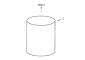
- an ingot of single crystal silicon carbide is produced, for example, by a sublimation method described below. That is, first, a seed crystal made of single crystal silicon carbide and a raw material powder made of silicon carbide are inserted into a container made of graphite. Next, the raw material powder is heated to sublimate silicon carbide and recrystallize on the seed crystal. At this time, recrystallization proceeds while a desired impurity such as nitrogen is introduced. As a result, the single crystal silicon carbide ingot 1 shown in FIG. 1 is obtained.
- the ingot 1 can be efficiently produced by setting the growth direction of the ingot 1 to the ⁇ 0001> direction as shown in FIG.
- the produced ingot 1 is cut to produce a silicon carbide substrate.
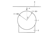
- the columnar (cylindrical) ingot 1 produced is set so that a part of the side surface is supported by the support base 2.
- the wire 9 travels in a direction along the diameter direction of the ingot 1, the wire 9 approaches the ingot 1 along the cutting direction ⁇ that is a direction perpendicular to the travel direction, and the wire 9 and the ingot 1 come into contact with each other.
- the ingot 1 is cut
- the angle between the ⁇ 11-20> direction or the ⁇ 1-100> direction of the ingot 1 is set to the ⁇ 0001 ⁇ plane.
- Cutting proceeds along the cutting direction ⁇ in the range of 15 ° ⁇ 5 ° in orthographic projection. More specifically, for example, as shown in FIG. 2, the angle ⁇ formed by the ⁇ 11-20> direction of the ingot 1 and the cutting direction ⁇ is 15 ° ⁇ 5 °.
- the value of the angle ⁇ is more preferably 15 ° ⁇ 2 °.
- the method for manufacturing silicon carbide substrate 3 in the present embodiment capable of reducing the warpage is particularly effective under such conditions.
- the manufacturing method of the silicon carbide substrate 3 in the present embodiment capable of reducing the warp is performed by the ingot 1 being cut by wire cutting. This is particularly effective when cut.
- Example 1 An experiment was conducted to compare the state of the main surface of the silicon carbide substrate in the method for manufacturing the silicon carbide substrate of the present invention with the state of the main surface of the conventional silicon carbide substrate.
- the experimental procedure is as follows.
- a single crystal silicon carbide ingot is prepared, and while being supported by the support base 2, wire cutting is performed so that cutting proceeds in a direction along the cleavage direction, A silicon carbide substrate was obtained. Then, the main surface of the silicon carbide substrate was flattened by polishing (conventional example). On the other hand, in the same procedure, wire cutting was performed so that cutting progressed in a direction in which the angle formed with the cleavage direction was 15 °, to obtain a silicon carbide substrate. And the main surface of the said silicon carbide substrate was planarized by grinding
- polishing Example
- the warpage of the surface is large and the surface roughness is improved by the flattening, but the warpage is large even after the flattening.
- the warpage of the surface was greatly improved at the time of cutting, and the surface roughness was improved by flattening. .
- the occurrence of warpage is suppressed as compared with the case of employing a conventional cutting method, and even when the substrate is flattened by polishing or the like, the surface on the main surface It was confirmed that variation in orientation can be greatly suppressed.
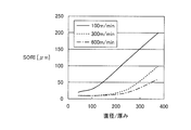
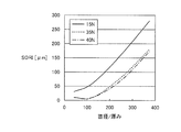
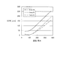
- Example 2 In the method for manufacturing a silicon carbide substrate of the present invention, an experiment was conducted to investigate the relationship between the value (D / T) of the diameter D with respect to the thickness T of the silicon carbide substrate and the warpage of the substrate. The experiment was conducted when the wire speed in wire cutting was changed, when the wire tension was changed, and when the cutting speed was changed. The test results are shown in FIGS. 8 to 10, the horizontal axis represents the D / T value, and the vertical axis represents the warp (SORI) value. In FIG. 8, when the wire speed is 100 m / min to 600 m / min, in FIG. 9, the wire tension is 15 N to 40 N, and in FIG. 10, the cutting speed is 1 mm / h to 6 mm / h. For cases, experimental results are shown.
- the warpage is particularly large when the value of D / T is 100 or more under any of the conditions. Therefore, it can be said that the method for manufacturing a silicon carbide substrate of the present invention capable of reducing warpage is particularly suitable when the value of D / T is 100 or more.
- the warpage is reduced as the wire speed increases.
- the warpage is greatly reduced by increasing the linear speed from 100 m / min to 300 m / min.
- the reduction range of the warp is from 100 m / min to 300 m / min. It is smaller than when it is raised to / min.
- the wire speed is preferably 300 m / min or more and 700 m / min or less.
- the warpage is reduced as the wire tension increases.
- the warpage is greatly reduced by increasing the tension from 15N to 35N.
- the reduction width of the warpage is smaller than that when the tension is increased from 15N to 35N.
- the tension exceeds 50 N the wire may be broken. Therefore, it is considered that the tension of the wire is preferably 35N or more and 50N or less.
- the warpage is reduced as the cutting speed decreases.
- the warpage is greatly reduced by reducing the cutting speed from 6 mm / h to 3 mm / h.
- the reduction width of the warp is 6 mm / h to 3 mm / h. It is smaller than the case where it is lowered to h.
- the cutting speed is less than 1 mm / h, the wire entrained with the cutting fluid such as slurry travels on the ingot with little advance, and the cutting margin increases, so the yield decreases. Therefore, it is considered that the cutting speed is preferably 1 mm / h or more and 3 mm / h or less.
- an ingot of single crystal silicon carbide is prepared as in the case of the above embodiment, and the angle formed with the ⁇ 1-100> direction which is the cleavage direction is ⁇ 0001 ⁇ plane while being supported by the support base 2
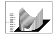
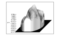
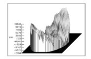
- a silicon carbide substrate was obtained by slicing the ingot so that the angle was 0 ° to 30 ° in an orthogonal projection.
- substrate was measured. The measurement results are shown in Table 1.
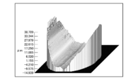
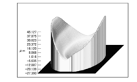
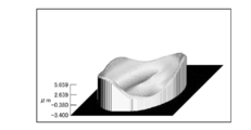
- the shape of the main surface of the obtained substrate is shown in FIGS.
- the SORI value of the substrate main surface becomes smaller. Yes. It is confirmed that the SORI value of the main surface of the substrate can be effectively reduced by setting the angle formed by the cutting progress direction and the ⁇ 1-100> direction to a range of 15 ° ⁇ 5 °. Further, it was found that the SORI value of the main surface of the substrate can be further reduced by setting the angle formed by the cutting progress direction and the ⁇ 1-100> direction to be in the range of 15 ° ⁇ 2 °.
- the method for manufacturing a silicon carbide substrate of the present invention can be particularly advantageously applied to the manufacture of a silicon carbide substrate that is required to suppress variations in plane orientation on the main surface.
Landscapes
- Chemical & Material Sciences (AREA)
- Engineering & Computer Science (AREA)
- Crystallography & Structural Chemistry (AREA)
- Materials Engineering (AREA)
- Metallurgy (AREA)
- Organic Chemistry (AREA)
- Mechanical Engineering (AREA)
- Inorganic Chemistry (AREA)
- Crystals, And After-Treatments Of Crystals (AREA)
- Mechanical Treatment Of Semiconductor (AREA)
- Processing Of Stones Or Stones Resemblance Materials (AREA)
- Finish Polishing, Edge Sharpening, And Grinding By Specific Grinding Devices (AREA)
Abstract
Description
本発明の炭化珪素基板の製造方法における炭化珪素基板の主面の状態を、従来の炭化珪素基板の主面の状態と比較する実験を行なった。実験の手順は以下の通りである。
本発明の炭化珪素基板の製造方法における炭化珪素基板の厚みTに対する直径Dの値(D/T)と基板の反りとの関係を調査する実験を行なった。実験は、ワイヤー切断における線速を変更した場合、ワイヤーの張力を変更した場合および切断速度を変更した場合について実施した。試験結果を図8~図10に示す。なお、図8~図10において横軸はD/Tの値、縦軸は反り(SORI)の値である。また、図8においてはワイヤーの線速が100m/min~600m/minの場合、図9においてはワイヤーの張力が15N~40Nの場合、図10においては切断速度が1mm/h~6mm/hの場合について、実験結果が示されている。
単結晶炭化珪素のインゴットを切断して基板を得る場合に、{0001}面への正射影における切断の進行方向と劈開方向とのなす角が、得られる基板の反り(SORI)に及ぼす影響を調査する実験を行なった。

Claims (6)
- 単結晶炭化珪素の結晶(1)を準備する工程と、
前記結晶(1)を切断することにより基板(3)を得る工程とを備え、
前記基板(3)を得る工程では、前記結晶(1)の<11-20>方向または<1-100>方向とのなす角が{0001}面への正射影において15°±5°の範囲となる方向に切断を進行させる、炭化珪素基板の製造方法。 - 前記基板(3)を得る工程では、前記結晶(1)の<11-20>方向または<1-100>方向とのなす角が{0001}面への正射影において15°±2°の範囲となる方向に切断を進行させる、請求項1に記載の炭化珪素基板の製造方法。
- 前記結晶(1)の成長方向は<0001>方向である、請求項1または2に記載の炭化珪素基板の製造方法。
- 前記結晶(1)の直径は2インチ以上である、請求項1~3のいずれか1項に記載の炭化珪素基板の製造方法。
- 前記基板(3)を得る工程では、前記基板(3)の厚みに対する直径の比が100以上となるように前記結晶(1)が切断される、請求項1~4のいずれか1項に記載の炭化珪素基板の製造方法。
- 前記基板(3)を得る工程では、前記結晶(1)はワイヤー切断により切断される、請求項1~5のいずれか1項に記載の炭化珪素基板の製造方法。
Priority Applications (3)
| Application Number | Priority Date | Filing Date | Title |
|---|---|---|---|
| JP2012547398A JP6011339B2 (ja) | 2011-06-02 | 2012-05-09 | 炭化珪素基板の製造方法 |
| DE112012002299.8T DE112012002299T5 (de) | 2011-06-02 | 2012-05-09 | Verfahren zum Herstellen eines Siliziumkarbidsubstrates |
| CN201280021347.3A CN103503119B (zh) | 2011-06-02 | 2012-05-09 | 碳化硅基板的制造方法 |
Applications Claiming Priority (2)
| Application Number | Priority Date | Filing Date | Title |
|---|---|---|---|
| JP2011123928 | 2011-06-02 | ||
| JP2011-123928 | 2011-06-02 |
Publications (1)
| Publication Number | Publication Date |
|---|---|
| WO2012165108A1 true WO2012165108A1 (ja) | 2012-12-06 |
Family
ID=47258972
Family Applications (1)
| Application Number | Title | Priority Date | Filing Date |
|---|---|---|---|
| PCT/JP2012/061834 Ceased WO2012165108A1 (ja) | 2011-06-02 | 2012-05-09 | 炭化珪素基板の製造方法 |
Country Status (5)
| Country | Link |
|---|---|
| US (2) | US9346187B2 (ja) |
| JP (1) | JP6011339B2 (ja) |
| CN (2) | CN107059135B (ja) |
| DE (1) | DE112012002299T5 (ja) |
| WO (1) | WO2012165108A1 (ja) |
Cited By (2)
| Publication number | Priority date | Publication date | Assignee | Title |
|---|---|---|---|---|
| JP2014195025A (ja) * | 2013-03-29 | 2014-10-09 | Sumco Techxiv株式会社 | 半導体単結晶インゴットのスライス方法 |
| JP2020075839A (ja) * | 2018-11-09 | 2020-05-21 | 株式会社新興製作所 | 窒化ガリウム系化合物半導体成長用SiC基板 |
Families Citing this family (4)
| Publication number | Priority date | Publication date | Assignee | Title |
|---|---|---|---|---|
| CN113334592A (zh) * | 2021-06-10 | 2021-09-03 | 河北同光晶体有限公司 | 碳化硅晶体的切割方法 |
| CN113752403A (zh) * | 2021-09-17 | 2021-12-07 | 宁波江丰电子材料股份有限公司 | 一种碳化硅靶材组件及其制备方法 |
| CN114643654A (zh) * | 2022-04-21 | 2022-06-21 | 青岛高测科技股份有限公司 | 十字线切割硅棒的方法、切割设备及切割系统 |
| CN114701085A (zh) * | 2022-04-21 | 2022-07-05 | 青岛高测科技股份有限公司 | 双线中垂切割硅棒的方法、切割设备及切割系统 |
Citations (3)
| Publication number | Priority date | Publication date | Assignee | Title |
|---|---|---|---|---|
| JP2006190909A (ja) * | 2005-01-07 | 2006-07-20 | Sumitomo Electric Ind Ltd | Iii族窒化物基板の製造方法 |
| JP2009152622A (ja) * | 2009-02-04 | 2009-07-09 | Sumitomo Electric Ind Ltd | Iii族窒化物基板及びその製造方法 |
| JP2011077325A (ja) * | 2009-09-30 | 2011-04-14 | Sumitomo Electric Ind Ltd | Iii族窒化物半導体基板の製造方法 |
Family Cites Families (31)
| Publication number | Priority date | Publication date | Assignee | Title |
|---|---|---|---|---|
| CA1119811A (en) * | 1980-01-25 | 1982-03-16 | Cominco Ltd. | Cutting apparatus for semi-conductor materials |
| JPH08143397A (ja) * | 1994-11-22 | 1996-06-04 | Nippon Steel Corp | 炭化珪素単結晶ウエハの製造方法および装置 |
| JP2842307B2 (ja) * | 1995-06-30 | 1999-01-06 | 住友電気工業株式会社 | Iii−v族化合物半導体結晶の切断方法 |
| JPH0929734A (ja) * | 1995-07-14 | 1997-02-04 | Tokyo Seimitsu Co Ltd | ワイヤソーのワーク接着ブロック |
| TW355151B (en) * | 1995-07-07 | 1999-04-01 | Tokyo Seimitsu Co Ltd | A method for cutting single chip material by the steel saw |
| JP3397968B2 (ja) * | 1996-03-29 | 2003-04-21 | 信越半導体株式会社 | 半導体単結晶インゴットのスライス方法 |
| CH692331A5 (de) * | 1996-06-04 | 2002-05-15 | Tokyo Seimitsu Co Ltd | Drahtsäge und Schneidverfahren unter Einsatz derselben. |
| JP3137600B2 (ja) * | 1997-09-12 | 2001-02-26 | 株式会社日平トヤマ | ワークの結晶方位調整方法 |
| JP3314921B2 (ja) * | 1999-06-08 | 2002-08-19 | 三菱住友シリコン株式会社 | 半導体材料の切断・加工方法 |
| US6329088B1 (en) * | 1999-06-24 | 2001-12-11 | Advanced Technology Materials, Inc. | Silicon carbide epitaxial layers grown on substrates offcut towards <1{overscore (1)}00> |
| DE60033574T2 (de) * | 2000-05-31 | 2007-11-15 | Memc Electronic Materials S.P.A. | Drahtsäge und verfahren zum gleichzeitigen schneiden von halbleiterbarren |
| DE10052154A1 (de) * | 2000-10-20 | 2002-05-08 | Freiberger Compound Mat Gmbh | Verfahren und Vorrichtung zum Trennen von Einkristallen, Justiervorrichtung und Testverfahren zum Ermitteln einer Orientierung eines Einkristalls für ein derartiges Verfahren |
| JP2002283340A (ja) * | 2001-03-26 | 2002-10-03 | Memc Japan Ltd | インゴットの切断方法 |
| DE10128630A1 (de) * | 2001-06-13 | 2003-01-02 | Freiberger Compound Mat Gmbh | Vorrichtung und Verfahren zur Bestimmung der Orientierung einer kristallografischen Ebene relativ zu einer Kristalloberfläche sowie Vorrichtung und Verfahren zum Trennen eines Einkristalls in einer Trennmaschine |
| JP3881562B2 (ja) * | 2002-02-22 | 2007-02-14 | 三井造船株式会社 | SiCモニタウェハ製造方法 |
| US6802928B2 (en) * | 2002-03-29 | 2004-10-12 | Sumitomo Mitsubishi Silicon Corporation | Method for cutting hard and brittle material |
| ATE418806T1 (de) * | 2004-04-02 | 2009-01-15 | Nichia Corp | Nitrid-halbleiterlaservorrichtung |
| DE102005017814B4 (de) * | 2004-04-19 | 2016-08-11 | Denso Corporation | Siliziumkarbid-Halbleiterbauelement und Verfahren zu dessen Herstellung |
| JP4951914B2 (ja) * | 2005-09-28 | 2012-06-13 | 信越半導体株式会社 | (110)シリコンウエーハの製造方法 |
| JP2007237627A (ja) * | 2006-03-10 | 2007-09-20 | Allied Material Corp | 単結晶サファイヤ基板の切断方法および切断装置 |
| JP2007237628A (ja) * | 2006-03-10 | 2007-09-20 | Allied Material Corp | 単結晶サファイヤ基板の切断方法および切断装置 |
| US7993453B2 (en) * | 2006-05-18 | 2011-08-09 | Showa Denko K.K. | Method for producing silicon carbide single crystal |
| US8222057B2 (en) * | 2006-08-29 | 2012-07-17 | University Of Florida Research Foundation, Inc. | Crack free multilayered devices, methods of manufacture thereof and articles comprising the same |
| EP2075106B1 (en) | 2006-10-20 | 2013-05-01 | Mitsubishi Electric Corporation | Slurry for silicon ingot cutting and method of cutting silicon ingot therewith |
| JP2009061528A (ja) | 2007-09-05 | 2009-03-26 | Denso Corp | ワイヤーによる炭化珪素基板の製造方法および炭化珪素基板製造用ワイヤーソー装置 |
| US8291895B2 (en) * | 2007-09-05 | 2012-10-23 | University Of South Carolina | Methods, wires, and apparatus for slicing hard materials |
| WO2009149299A1 (en) * | 2008-06-04 | 2009-12-10 | Sixpoint Materials | Methods for producing improved crystallinty group iii-nitride crystals from initial group iii-nitride seed by ammonothermal growth |
| JP5475772B2 (ja) * | 2008-07-11 | 2014-04-16 | サンーゴバン アブレイシブズ,インコーポレイティド | ワイヤスライシングシステム |
| DE102008051673B4 (de) * | 2008-10-15 | 2014-04-03 | Siltronic Ag | Verfahren zum gleichzeitigen Auftrennen eines Verbundstabs aus Silicium in eine Vielzahl von Scheiben |
| CN101979230B (zh) * | 2010-05-21 | 2013-10-23 | 北京天科合达蓝光半导体有限公司 | 多线切割机分段切割碳化硅晶体的方法 |
| JP2013008769A (ja) * | 2011-06-23 | 2013-01-10 | Sumitomo Electric Ind Ltd | 炭化珪素基板の製造方法 |
-
2012
- 2012-05-09 WO PCT/JP2012/061834 patent/WO2012165108A1/ja not_active Ceased
- 2012-05-09 CN CN201610853198.7A patent/CN107059135B/zh active Active
- 2012-05-09 JP JP2012547398A patent/JP6011339B2/ja active Active
- 2012-05-09 CN CN201280021347.3A patent/CN103503119B/zh active Active
- 2012-05-09 DE DE112012002299.8T patent/DE112012002299T5/de not_active Withdrawn
- 2012-05-31 US US13/484,724 patent/US9346187B2/en active Active
-
2016
- 2016-04-14 US US15/098,918 patent/US9844893B2/en active Active
Patent Citations (3)
| Publication number | Priority date | Publication date | Assignee | Title |
|---|---|---|---|---|
| JP2006190909A (ja) * | 2005-01-07 | 2006-07-20 | Sumitomo Electric Ind Ltd | Iii族窒化物基板の製造方法 |
| JP2009152622A (ja) * | 2009-02-04 | 2009-07-09 | Sumitomo Electric Ind Ltd | Iii族窒化物基板及びその製造方法 |
| JP2011077325A (ja) * | 2009-09-30 | 2011-04-14 | Sumitomo Electric Ind Ltd | Iii族窒化物半導体基板の製造方法 |
Cited By (2)
| Publication number | Priority date | Publication date | Assignee | Title |
|---|---|---|---|---|
| JP2014195025A (ja) * | 2013-03-29 | 2014-10-09 | Sumco Techxiv株式会社 | 半導体単結晶インゴットのスライス方法 |
| JP2020075839A (ja) * | 2018-11-09 | 2020-05-21 | 株式会社新興製作所 | 窒化ガリウム系化合物半導体成長用SiC基板 |
Also Published As
| Publication number | Publication date |
|---|---|
| US9346187B2 (en) | 2016-05-24 |
| JPWO2012165108A1 (ja) | 2015-02-23 |
| CN103503119A (zh) | 2014-01-08 |
| CN107059135A (zh) | 2017-08-18 |
| US9844893B2 (en) | 2017-12-19 |
| CN103503119B (zh) | 2016-10-19 |
| US20160229086A1 (en) | 2016-08-11 |
| JP6011339B2 (ja) | 2016-10-19 |
| US20120304839A1 (en) | 2012-12-06 |
| CN107059135B (zh) | 2019-08-13 |
| DE112012002299T5 (de) | 2014-05-15 |
Similar Documents
| Publication | Publication Date | Title |
|---|---|---|
| US9896781B2 (en) | Silicon carbide single-crystal substrate, silicon carbide epitaxial substrate and method of manufacturing them | |
| US10269554B2 (en) | Method for manufacturing SiC epitaxial wafer and SiC epitaxial wafer | |
| JP6011339B2 (ja) | 炭化珪素基板の製造方法 | |
| JP6102927B2 (ja) | 高硬度材料のマルチワイヤーソーによる切断方法 | |
| US20160122899A1 (en) | METHOD FOR CULTIVATING BETA-Ga2O3 SINGLE CRYSTAL, AND BETA-Ga2O3-SINGLE-CRYSTAL SUBSTRATE AND METHOD FOR PRODUCING SAME | |
| TWI851250B (zh) | 碳化矽單結晶基板 | |
| US20130099252A1 (en) | Method of manufacturing silicon carbide substrate and silicon carbide substrate | |
| WO2012176755A1 (ja) | 炭化珪素基板の製造方法 | |
| WO2015076037A1 (ja) | 炭化珪素インゴットおよび炭化珪素基板の製造方法 | |
| JP6722578B2 (ja) | SiCウェハの製造方法 | |
| JP6583989B2 (ja) | SiC単結晶シード、SiCインゴット、SiC単結晶シードの製造方法及びSiC単結晶インゴットの製造方法 | |
| JP6260603B2 (ja) | 炭化珪素単結晶基板、炭化珪素エピタキシャル基板およびこれらの製造方法 | |
| JP2015135902A (ja) | ウェハの製造方法およびウェハの製造装置 | |
| WO2023074174A1 (ja) | 炭化珪素基板および炭化珪素基板の製造方法 | |
| JP2016007690A (ja) | サファイア基板の製造方法 | |
| JP2015127068A (ja) | 炭化珪素基板の製造方法 | |
| JP2018039730A (ja) | 炭化珪素インゴットおよび炭化珪素基板の製造方法 |
Legal Events
| Date | Code | Title | Description |
|---|---|---|---|
| ENP | Entry into the national phase |
Ref document number: 2012547398 Country of ref document: JP Kind code of ref document: A |
|
| 121 | Ep: the epo has been informed by wipo that ep was designated in this application |
Ref document number: 12792703 Country of ref document: EP Kind code of ref document: A1 |
|
| WWE | Wipo information: entry into national phase |
Ref document number: 1120120022998 Country of ref document: DE Ref document number: 112012002299 Country of ref document: DE |
|
| 122 | Ep: pct application non-entry in european phase |
Ref document number: 12792703 Country of ref document: EP Kind code of ref document: A1 |