WO2012164706A1 - 車両の操舵制御装置 - Google Patents
車両の操舵制御装置 Download PDFInfo
- Publication number
- WO2012164706A1 WO2012164706A1 PCT/JP2011/062632 JP2011062632W WO2012164706A1 WO 2012164706 A1 WO2012164706 A1 WO 2012164706A1 JP 2011062632 W JP2011062632 W JP 2011062632W WO 2012164706 A1 WO2012164706 A1 WO 2012164706A1
- Authority
- WO
- WIPO (PCT)
- Prior art keywords
- steering
- vehicle
- wheel
- neutral position
- value
- Prior art date
- Legal status (The legal status is an assumption and is not a legal conclusion. Google has not performed a legal analysis and makes no representation as to the accuracy of the status listed.)
- Ceased
Links
Images


Classifications
-
- B—PERFORMING OPERATIONS; TRANSPORTING
- B62—LAND VEHICLES FOR TRAVELLING OTHERWISE THAN ON RAILS
- B62D—MOTOR VEHICLES; TRAILERS
- B62D6/00—Arrangements for automatically controlling steering depending on driving conditions sensed and responded to, e.g. control circuits
-
- B—PERFORMING OPERATIONS; TRANSPORTING
- B62—LAND VEHICLES FOR TRAVELLING OTHERWISE THAN ON RAILS
- B62D—MOTOR VEHICLES; TRAILERS
- B62D5/00—Power-assisted or power-driven steering
- B62D5/008—Changing the transfer ratio between the steering wheel and the steering gear by variable supply of energy, e.g. by using a superposition gear
-
- B—PERFORMING OPERATIONS; TRANSPORTING
- B62—LAND VEHICLES FOR TRAVELLING OTHERWISE THAN ON RAILS
- B62D—MOTOR VEHICLES; TRAILERS
- B62D5/00—Power-assisted or power-driven steering
- B62D5/04—Power-assisted or power-driven steering electrical, e.g. using an electric servo-motor connected to, or forming part of, the steering gear
- B62D5/0457—Power-assisted or power-driven steering electrical, e.g. using an electric servo-motor connected to, or forming part of, the steering gear characterised by control features of the drive means as such
- B62D5/0481—Power-assisted or power-driven steering electrical, e.g. using an electric servo-motor connected to, or forming part of, the steering gear characterised by control features of the drive means as such monitoring the steering system, e.g. failures
-
- B—PERFORMING OPERATIONS; TRANSPORTING
- B62—LAND VEHICLES FOR TRAVELLING OTHERWISE THAN ON RAILS
- B62D—MOTOR VEHICLES; TRAILERS
- B62D7/00—Steering linkage; Stub axles or their mountings
- B62D7/06—Steering linkage; Stub axles or their mountings for individually-pivoted wheels, e.g. on king-pins
- B62D7/14—Steering linkage; Stub axles or their mountings for individually-pivoted wheels, e.g. on king-pins the pivotal axes being situated in more than one plane transverse to the longitudinal centre line of the vehicle, e.g. all-wheel steering
- B62D7/15—Steering linkage; Stub axles or their mountings for individually-pivoted wheels, e.g. on king-pins the pivotal axes being situated in more than one plane transverse to the longitudinal centre line of the vehicle, e.g. all-wheel steering characterised by means varying the ratio between the steering angles of the steered wheels
- B62D7/159—Steering linkage; Stub axles or their mountings for individually-pivoted wheels, e.g. on king-pins the pivotal axes being situated in more than one plane transverse to the longitudinal centre line of the vehicle, e.g. all-wheel steering characterised by means varying the ratio between the steering angles of the steered wheels characterised by computing methods or stabilisation processes or systems, e.g. responding to yaw rate, lateral wind, load, road condition
Definitions
- the present invention can change the relationship between the steering angle and the steering angle of the steered wheel independently from the steering input of the driver, for example, VGRS (Variable Gear Ratio Steering) or ARS (Active Rear).
- Steer a vehicle equipped with steering angle variable means such as a rear wheel steering angle variable device) and assist means such as EPS (Electronic-controlled Power-steering) that can assist driver steering torque
- EPS Electronic-controlled Power-steering
- Patent Document 1 Some types of vehicles deal with a voltage drop of a battery that functions as a power supply source for the steering angle varying means (see Patent Document 1).
- the vehicle steering control device disclosed in Patent Document 1 when it is detected that the voltage of the battery is equal to or lower than a predetermined driving means fixed voltage, the rotation angle of the VGRS as the driving means is fixed. . Further, at the time of detecting the steering wheel turnback thereafter, the deviation between the neutral position of the steering wheel (also referred to as a steering wheel) and the straight traveling position of the vehicle, which occurs when the rotation angle of the driving means is fixed, is corrected. For this reason, it is supposed that the shift between the neutral position of the steering wheel and the straight vehicle position can be corrected while suppressing the load on the battery.
- a desired change in the steering angle can be given to the steering angle, which is the steering angle of the driver's steering wheel (rotation angle of the steering wheel), through, for example, a motor or an actuator.
- the change in the steering angle given in this way is canceled at the time of turning and turning back, so that when the steering wheel is returned to the neutral position, the steering angle of the steered wheels also causes the vehicle to travel straight ahead. Return to the rudder angle neutral point. That is, the neutral position of the steering wheel and the neutral position of the steered wheel are in agreement with each other.
- Patent Document 1 still has room for improvement in steering feeling when the battery voltage drops in a vehicle equipped with steering angle variable means.
- Patent Document 2 does not give any suggestion regarding how to deal with the case where the battery voltage drops while the vehicle is running, and such a problem may occur as well.
- Patent Document 3 gives suggestions on the EPS driving method at the time of a voltage drop, but no control method of VGRS at the time of the battery voltage drop is specified, and the above-described problem is solved. I can't guide you.
- the present invention has been made in view of such problems, and in a vehicle including a steering angle varying unit and a steering torque assist unit, the vehicle steering control capable of alleviating the degree of deterioration of steering feeling when the battery voltage drops. It is an object to provide an apparatus.
- a vehicle steering control device includes a steering angle variable means and a driver steering torque capable of changing a relationship between a steering angle as a rotation angle of a steering wheel and a steering angle of a steering wheel.
- a steering control device for a vehicle comprising: a steering system including at least steering torque assisting means capable of assisting power; and a power supply source that supplies power to the steering system, wherein the power supply capability of the power supply source Supply capacity specifying means for specifying, consumption current specifying means for specifying the current consumption value of the steering system, and when the specified supply capacity is lower than a reference, the specified current consumption value is Limiting means for limiting the current consumption of the steering torque assist means when the steering system is larger than the maximum allowable current value of the steering system; Control means for controlling the steering angle varying means so that a neutral position of the steering wheel and a neutral position of the steered wheel coincide with each other in a state where current consumption of the strike means is limited ( Claim 1).
- a vehicle steering control device is mounted on a vehicle including a steering system including a steering angle varying unit and a steering torque assisting unit, and a power supply source for supplying electric power to the steering system.
- a processor and the like are included, and a memory, a sensor, and the like are appropriately provided as necessary.
- the steering angle varying means is means capable of changing the relationship between the steering angle (meaning the rotation angle of the steering wheel) and the steering angle of the steered wheels, and preferably the steered angle related to the front wheels such as VGRS. It means various by-wire devices such as a variable device and a steering angle variable device related to rear wheels such as ARS, or SBW (Steer By Wire: electronically controlled steering angle variable device).
- the steering torque assist means is means capable of supplying an assist torque for assisting a steering torque (that is, driver steering torque) given by a driver via a steering input means such as a steering wheel.
- the assist torque is supplied to various destinations.
- the steering wheel is connected to the steering output shaft through various steering mechanisms such as a rack and pinion mechanism, and the VGRS is between the steering output shaft and the steering input shaft.
- the assist torque assists the linear motion of the rack bar, whether it is used to assist the rotation of the steering output shaft or to assist the rotation of the pinion gear. May be used for
- the assist torque is torque that can be applied in the same direction as the driver steering torque or in the opposite direction.
- the assist torque can reduce the driver's steering burden (in the narrow sense), and when acting in the opposite direction to the driver steering torque, The assist torque increases the steering burden on the driver or can operate the steering wheel in the direction opposite to the steering direction of the driver (this is also an assist category in a broad sense).
- the assist torque control target may be set as an added value of a plurality of control terms such as an inertia control term corresponding to the inertial characteristic of the steering mechanism and a damping control term corresponding to the viscosity characteristic of the steering mechanism.
- Various steering feelings can be realized according to the control mode of each control term, for example, various gain setting modes.
- the assist torque is a reaction force caused by a self-aligning torque that acts around the kingpin axis of the steering wheel, which is transmitted from the steering wheel to the steering input means (in short, the steering wheel).
- the steering reaction force can also be reduced or offset by acting in a direction that cancels a certain).
- the power supply source that supplies power to these is, for example, a vehicle-mounted battery device having a normal no-load voltage of about 12 V at normal times, and can supply generated power to the battery device. It means power generation means such as an alternator that can directly supply power to various electrical accessories without going through a battery device.
- power generation means such as an alternator that can directly supply power to various electrical accessories without going through a battery device.
- an EV (Electric Vehicle) or a hybrid vehicle including various rotating electric machines such as a motor and a motor generator travels from the rotating electric machine.
- It may be a secondary battery device having a no-load voltage of several hundred volts, which is obtained by connecting several hundreds of secondary battery cells having a cell voltage of about several volts, which are installed exclusively for supplying power.
- the power supply capability of the power supply source is specified, and the current consumption value of the steering system is specified.
- “specific” is a concept that broadly encompasses final determination as a reference value, such as detection, calculation, derivation, estimation, identification, selection, and acquisition.
- the power supply capacity of the power supply source changes according to the deterioration state, temperature state, load state, etc. of the power supply source, and the current consumption value of the steering system depends on the driving condition of the vehicle and the driving condition of the steering system. Change.
- power supply capacity does not necessarily mean an unambiguous physical quantity, but at least when “supply capacity is low”, the power supply source is higher than when “supply capacity is high”.
- the driving or operation of a device (including a steering system) that uses the motor is relatively limited.
- the supply capacity as such a meaning is, for example, binary based on the no-load voltage value, supply voltage value, supply current value, storage amount, charge amount, discharge amount or charge / discharge balance of the power supply source. (In short, the supply capacity is “high” or “low”) or can be defined in multiple stages. Alternatively, it can be defined as an index value or function that can change continuously (ie, seamless).
- the steering system can operate without problems if the power supply source is operating in the normal operating range. However, if the power supply capability of the power supply source is below the standard, Depending on the current consumption value, the operation of some devices may be hindered.
- Such “reference” can be determined in advance experimentally, empirically, or theoretically from the viewpoint of whether or not the steering system can be operated without any problem in practice. Or it can set suitably based on the setting process previously determined experimentally, empirically, or theoretically.
- the current consumption value of the steering system is permitted to be used by the steering system at that time (such permission may be given by, for example, a mechanical configuration or an electric control mode). If it is greater than the maximum allowable current value, the steering angle variable means and / or the steering torque assist means may not be able to exhibit the assumed performance. In particular, when the rudder angle variable means falls into an overload state, the neutral position of the steering wheel and the neutral position of the steered wheel as described above will arise in the situation where some rudder angle change has already been applied. obtain.
- the steering angle change of the steered wheel can be obtained by the steering wheel operation even when the steering angle variable means is inactive, and the steering Considering the magnitude of the driver's burden when operating the steering wheel without assisting torque, the judgment that the operation of the steering torque assist means should be given priority can be made with appropriateness.
- the vehicle steering control device provides a current consumption value specified by the current consumption specifying means when the power supply capacity of the power supply source specified by the supply capacity specifying means is lower than the reference. Is greater than the maximum allowable current value of the steering system, the current consumption of the steering torque assist means is first restricted by the action of the restriction means. Further, in such a state where the current consumption of the steering torque assist means is limited, the neutral position of the steering wheel (ie, the steering angle neutral point) and the neutral position of the steering wheel (the steering angle neutral position) are caused by the action of the control means.
- the rudder angle varying means is controlled so as to coincide with the point).
- the operation of the steering torque assist means is temporarily restricted, and the power that can reliably operate the steering angle varying means is ensured. Priority is given to the matching between the neutral position of the steering wheel and the neutral position of the steering wheel.
- the vehicle is not forced to travel without the neutral position of the steering wheel and the neutral position of the steering wheel being in agreement with each other, and a comfortable steering feeling can be provided to the driver. It becomes possible to provide.
- the supply capability specifying means specifies the supply capability based on a supply voltage value of the power supply source.
- the “reference” relating to the above-described supply capability can be alternatively defined by a reference voltage value that can be set for this supply voltage value.
- the “reference voltage value” may be a normal no-load voltage value grasped in advance, but from a practical viewpoint, the power supply source has a current consumption value of the steering system due to its internal resistance. A voltage drop corresponding to the maximum current consumption value of the steering system (such a value can be determined by specifications) at least for a normal no-load voltage value is normal operation. It can also occur in range.
- the reference voltage value may be a value obtained by subtracting this type of voltage drop from the normal no-load voltage value.
- an operation guarantee voltage in terms of design or specification can be defined for each of the rudder angle variable means and the steering torque assist means constituting the steering system.
- the guaranteed operating voltage is a voltage that is lower than the normal no-load voltage value of the power supply source, and that can sufficiently handle practically the driving conditions belonging to the use range assumed in advance of the steering system.
- the protection setting voltage value for the steering torque assist means defined as the one that should immediately stop the steering torque assist means
- the protection for the rudder angle variable means defined as one that should immediately stop the steering angle variable means
- the voltage value is higher than the higher one of the set voltage values.
- the voltage value is higher than the voltage drop caused by the internal resistance described above (for example, a margin on the safe side may be included) with respect to the relatively high protection set voltage value.
- the reference voltage value related to the supply voltage value may be an operation guarantee voltage value having such technical significance.
- the supply capacity specifying means specifies the supply capacity based on a charge / discharge balance of the power supply source (Claim 3).
- the supply capability of the power supply source having a high correlation with the power supply capability of the power supply source. More specifically, in a situation where the charge / discharge balance is inclined to the negative side (excessive discharge), it can be said that the supply capacity of the power supply source is low, and the charge / discharge balance is inclined to the plus / minus zero or positive side. In (overcharge), it can be said that the supply capacity of the power supply source is high.
- the charge / discharge balance of the power supply source may have a unique relationship with the difference between the input power and the output power of the battery when the power supply source is a battery. If the alternator is considered as a part of the power supply source in addition to the battery, it may have a unique relationship with the difference between the generated power of the alternator and the discharge power of the battery.
- the rudder angle varying means includes a lock mechanism that uniquely fixes the relationship
- the control means includes a neutral position of the steering wheel and the steering position. After matching the neutral position of the wheel, the locking mechanism is controlled so that the relationship is uniquely fixed (Claim 4).
- the steering angle varying means since the steering angle varying means is in the locked state after the neutral position is matched by the action of the lock mechanism, the steering angle and the steering angle are thereafter changed until the locked state is released.
- the relationship is physically fixed with a uniquely high reliability. Therefore, the physical protection of the steering angle varying means can be suitably achieved along with the effect related to the reduction in steering feeling.
- the limiting means limits the current consumption in accordance with the maximum allowable current value (Claim 5).
- the limiting means limits the current consumption of the steering torque assisting means, as long as it is conceptually compared as long as the current for ensuring the neutral position of the steering wheel and the neutral position of the steering wheel is secured.
- the degree of restriction is small.
- the restriction is relaxed as the maximum allowable current value permitted to be used in the steering system is increased, and the degree of restriction is increased as the maximum allowable current value is decreased. Therefore, the assist of the driver steering torque by the assist torque can be continued as much as possible within a range in which the measures relating to the neutral position matching can be advanced without delay.
- the steering angle varying means includes a front wheel steering angle varying means having a front wheel as the steering wheel, and a rear wheel steering angle varying means having a rear wheel as the steering wheel.
- the control means is one of the front wheel rudder angle varying means and the rear wheel rudder angle varying means having a large amount of deviation of the steering wheel from the neutral position with respect to the neutral position of the steering wheel. Is controlled with priority (claim 6).
- the vehicle includes the front wheel rudder angle varying means and the rear wheel rudder angle varying means as the rudder angle varying means.
- the current consumption value of the steering system exceeds the maximum allowable current value, it has an important meaning from which rudder angle variable means to execute the measure for matching the neutral position first. obtain. For example, if it is possible to improve the driver's feelings ahead of the measure for one of the steering angle variable means than the measure for the other, it is reasonable to precede the measure for the one. It can be a reason.
- the measure for matching the neutral position is started in preference to the steering angle variable means having the larger deviation amount (that is, the steering off-center angle) between the neutral position of the steering wheel and the neutral position of the steering wheel. Is done. Therefore, it is possible to minimize the deflection of the vehicle that does not conform to the driver's feeling and suppress the deterioration of the steering feeling as much as possible.
- the amount of deviation from the neutral position of the steering wheel with respect to the neutral position of the steering wheel may be calculated each time.
- the front wheel steering angle variable means and the rear wheel steering angle variable Among the means the means having the larger deviation amount from the neutral position of the steering wheel with respect to the neutral position of the steering wheel at the time of maximum steering angle control may be determined in advance in the design stage or the experimental stage as a priority object.
- the vehicle includes an internal combustion engine and an alternator
- the maximum allowable current value is a vehicle speed, an outside air temperature, an engine rotation speed of the internal combustion engine, or power generation of the alternator. It is variable according to the amount (Claim 7).
- the maximum allowable current value is a current value permitted to be used by the steering system at that time due to physical, electrical or control restrictions. Therefore, it is not necessarily a fixed value, and preferably a variable value.
- the power value required for braking the vehicle increases at higher vehicle speed ranges (for example, the drive power of the electrically driven pump of the brake actuator is relatively higher). Need a lot).
- the power supply source is likely to suffer performance degradation (for example, reduction in charge / discharge efficiency and charge / discharge speed) even when the outside air temperature is too high or too low. Further, even in a regular area where such performance degradation does not occur, if the outside air temperature is high, the power consumption of the air conditioner tends to increase, and the maximum allowable current value tends to be limited accordingly.
- the power generated by the alternator can be used as drive power for the steering system. .
- the power generated by the alternator can be used for charging the power supply source.
- An alternator can also be considered as a kind of “power supply source” according to the present invention. Therefore, in a situation where the power generation amount of the alternator is relatively large, the maximum allowable current value should be set higher for one supply capacity of the power supply source than in a situation where the power generation amount of the alternator is relatively small. Can do.
- the steering torque assisting means can be more finely limited in accordance with the traveling conditions of the vehicle at that time, and the effect related to the suppression of the steering feeling reduction can be obtained efficiently.
- the vehicle includes a braking system that shares the power supply source with the steering system, and the maximum allowable current value is determined by the steering system and the braking system. It is a value obtained by subtracting a current value used by the braking system from a current value that can be used at least by the entire chassis system.
- the vehicle is equipped with a braking system such as an ECB (Electronic Controlled Braking System), and the power supply source is shared with the steering system.
- a braking system such as an ECB (Electronic Controlled Braking System)
- the power supply source is shared with the steering system.
- the current value that can be used in the entire chassis system including the braking system and the steering system for example, a value established at the time of vehicle design or the like can be used, or it can be determined as a value that appropriately changes in vehicle travel control.
- a value established at the time of vehicle design or the like can be used, or it can be determined as a value that appropriately changes in vehicle travel control.
- the braking system and the steering system are compared, it is considered that power supply to the braking system should be prioritized from the viewpoint of securing a thicker vehicle safety.
- a value obtained by subtracting a current value used or required by the braking system from a current value usable in the entire chassis system is set as a current value permitted to the steering system. For this reason, the braking performance of the vehicle is reliably ensured, and the balance of behavior control as the entire vehicle is suitably maintained.
- FIG. 1 is a schematic configuration diagram conceptually illustrating a configuration of a vehicle according to an embodiment of the present invention. It is a simplified sectional view of the VGRS actuator in the vehicle of FIG. It is a block diagram of the electric power supply system in the vehicle of FIG. It is a flowchart of the steering system control process performed in the vehicle of FIG. 5 is a flowchart of a neutral position lock process in the steering system control process of FIG. 4. It is the figure which represented the characteristic of the steering system control process of FIG. 4 visually.
- FIG. 1 is a schematic configuration diagram conceptually showing the basic configuration of the vehicle 10.
- the vehicle 10 includes a left front wheel FL, a right front wheel FR, a left rear wheel RL, and a right rear wheel RR.
- the steering angle change of the left front wheel FL and the right front wheel FR which are steering wheels, It is configured to be able to travel in a desired direction by changing the steering angle of the left rear wheel FL and the right rear wheel FR.
- the vehicle 10 includes an ECU 100, an engine 200, a driving force distribution device 300, a VGRS actuator 400, an EPS actuator 500, an ECB 600, and an ARS actuator 700.
- the ECU 100 is an electronic control unit that includes a CPU (Central Processing Unit), a ROM (Read Only Memory), and a RAM (Random Access Memory) (not shown), and is configured to be able to control the entire operation of the vehicle 10. 1 is an example of a “vehicle steering control device”.
- the ECU 100 is configured to execute a steering system control process, which will be described later, according to a control program stored in the ROM.
- the ECU 100 is an integrated electronic control unit configured to function as an example of each of the “supply capability specifying means”, “consumption current specifying means”, “limit means”, and “control means” according to the present invention.
- the operations related to these means are all configured to be executed by the ECU 100.
- the physical, mechanical, and electrical configurations of each of the units according to the present invention are not limited to this.
- each of these units includes a plurality of ECUs, various processing units, various controllers, a microcomputer device, and the like. It may be configured as various computer systems.
- Engine 200 is an example of an “internal combustion engine” according to the present invention that functions as a power source for vehicle 10.
- the “internal combustion engine” according to the present invention is a concept that encompasses an engine that can convert thermal energy accompanying combustion of fuel into kinetic energy and finally extract it as rotation of a power shaft (for example, a crankshaft). is there. Accordingly, in the internal combustion engine of the present invention, for example, the fuel type, the fuel supply mode, the fuel injection mode, the intake / exhaust system configuration, the valve operating system configuration, the exhaust purification device mode, the presence / absence of supercharging, the number of cylinders and Cylinder arrangement etc. are free.
- the ECU 100 is configured to be able to acquire sensor outputs from various sensors necessary for operation control of the engine 200 at a constant or indefinite period.
- This type of sensor includes, for example, an air-fuel ratio sensor that detects the air-fuel ratio, a water temperature sensor that detects the coolant temperature, a crank position sensor that detects the rotational position of the crankshaft, a throttle position sensor that detects the rotational position of the throttle valve, and An air flow meter for detecting the amount of intake air is included.
- the ECU 100 can calculate the engine rotational speed NE of the engine 200 by processing the sensor output of the crank position sensor at any time (if a sensor such as an NE sensor is provided, obtain the sensor output). Just do it).
- the power source of the vehicle according to the present invention is limited to an internal combustion engine (engine 200 is an example thereof) having various practical aspects as a concept encompassing an engine that can take out fuel combustion by converting it into mechanical power.
- a rotating electrical machine such as a motor may be used.
- the vehicle may be a so-called hybrid vehicle in which these are cooperatively controlled.
- a crankshaft that is a driving force output shaft of the engine 200 is connected to a center differential device 310 that is a component of the driving force distribution device. It should be noted that the detailed configuration of the engine 200 has little correlation with the gist of the present invention, and therefore the details are omitted here.
- the driving force distribution device 300 is configured to be able to distribute the engine torque Te transmitted from the engine 200 via the crankshaft to the front wheels and the rear wheels at a predetermined ratio, and further to each of the front wheels and the rear wheels. It is an apparatus configured to be able to change the driving force distribution of the left and right wheels.
- the driving force distribution device 300 includes a center differential device 310 (hereinafter appropriately referred to as “center differential 310”), a front differential device 320 (hereinafter appropriately referred to as “front differential 320”), and a rear differential device 330 (hereinafter, referred to as “center differential 310”). Appropriately referred to as “rear differential 330”).
- the center differential 310 is an LSD (Limited Slip if Differential: differential mechanism with a differential limiting function) that distributes the engine torque Te supplied from the engine 200 to the front differential 320 and the rear differential 330.
- the center differential 310 distributes the engine torque Te to the front and rear wheels at a distribution ratio of 50:50 (an example is not limited) under conditions where the load acting on the front and rear wheels is substantially constant. Further, when the rotational speed of one of the front and rear wheels becomes higher than a predetermined value with respect to the other, a differential limiting torque is applied to the one, and a differential limiting is performed in which torque is transferred to the other. . That is, the center differential 310 is a so-called rotational speed-sensitive (viscous coupling type) differential mechanism.
- the center differential 310 is not limited to such a rotational speed sensitive type, but may be a torque sensitive type differential mechanism in which the differential limiting action increases in proportion to the input torque. Also, a differential ratio variable type differential that can achieve a desired distribution ratio within a predetermined adjustment range by making a differential action by the planetary gear mechanism and continuously changing the differential limiting torque by the intermittent control of the electromagnetic clutch. It may be a mechanism. In any case, the center differential 310 may take various practical aspects regardless of whether it is publicly known or not known as long as the engine torque Te can be distributed to the front wheels and the rear wheels.
- the front differential 320 can distribute the engine torque Te distributed to the front axle (front wheel axle) side by the center differential 310 further to the left and right wheels at a desired distribution ratio set within a predetermined adjustment range.
- the front differential 320 includes a planetary gear mechanism including a ring gear, a sun gear, and a pinion carrier, and an electromagnetic clutch that provides a differential limiting torque.
- a differential case is provided for the ring gear of the planetary gear mechanism, and left and right axles are provided for the sun gear and the carrier, respectively. Takes a linked configuration.
- the differential limiting torque is continuously controlled by energization control on the electromagnetic clutch, and the torque distribution ratio is continuously variably controlled within a predetermined adjustment range determined by the physical and electrical configuration of the front differential 320. It is the composition which becomes.
- the front differential 320 is electrically connected to the ECU 100, and the energization control of the electromagnetic clutch is also controlled by the ECU 100. Therefore, the ECU 100 can generate a desired front wheel left / right braking / driving force difference (here, the driving force difference) F f through the drive control of the front differential 320.
- the configuration of the front differential 320 is limited to that exemplified here as long as the driving force (note that the torque and the driving force are uniquely related) can be distributed to the left and right wheels at a desired distribution ratio. It can have various aspects regardless of whether it is publicly known or not known. In any case, such a right / left driving force distribution action is known, and here, the details thereof will not be mentioned for the purpose of preventing the explanation from becoming complicated.
- the rear differential 330 distributes the engine torque Te distributed to the rear axle (rear axle) via the propeller shaft 11 by the center differential 310, and further at a desired distribution ratio set within a predetermined adjustment range for the left and right wheels.
- This is a variable distribution ratio LSD that can be distributed.
- the rear differential 330 includes a planetary gear mechanism including a ring gear, a sun gear, and a pinion carrier, and an electromagnetic clutch that provides differential limiting torque.
- a differential case is connected to the ring gear of the planetary gear mechanism, and left and right axles are connected to the sun gear and the carrier, respectively.
- Adopted configuration The differential limiting torque is continuously controlled by energization control for the electromagnetic clutch, and the torque distribution ratio is continuously variably controlled within a predetermined adjustment range determined by the physical and electrical configuration of the rear differential 330. It has a configuration.
- the rear differential 330 is electrically connected to the ECU 100, and the energization control of the electromagnetic clutch is also controlled by the ECU 100. Therefore, ECU 100, via the drive control of the rear differential 330, (here, a is the driving force difference) desired rear wheel left and right longitudinal force difference it is possible to cause F r.
- the configuration of the rear differential 330 is limited to that illustrated here as long as the driving force (where torque and driving force are uniquely related) can be distributed to the left and right wheels at a desired distribution ratio. It can have various aspects regardless of whether it is publicly known or not. In any case, such a right / left driving force distribution action is known, and here, the details thereof will not be mentioned for the purpose of preventing the explanation from becoming complicated.
- the steering input given by the driver via the handle 12 is connected to the handle 12 so as to be coaxially rotatable, and is an axis that can rotate in the same direction as the handle 12. Communicated.
- the upper steering shaft 13 is connected to the VGRS actuator 400 at its downstream end.
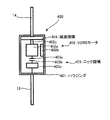
- FIG. 2 is a simplified cross-sectional view of the VGRS actuator 400.
- the same reference numerals are given to the same portions as those in FIG. 1, and the description thereof will be omitted as appropriate.
- the VGRS actuator 400 includes a housing 401, a VGRS motor 402, a lock mechanism 403, and a speed reduction mechanism 404.
- the housing 401 is a housing of the VGRS actuator 400 that houses the VGRS motor 402, the lock mechanism 403, and the speed reduction mechanism 404.
- the downstream end of the above-described upper steering shaft 13 is fixed to the housing 401, and the housing 401 can rotate integrally with the upper steering shaft 13.
- the VGRS motor 402 is a DC brushless motor having a rotor 402a serving as a rotor, a stator 402b serving as a stator, and a rotating shaft 402c serving as an output shaft for driving force.
- the stator 402b is fixed inside the housing 401, and the rotor 402a is rotatably held inside the housing 401.
- the rotary shaft 402c is fixed to the rotor 402a so as to be coaxially rotatable with the rotor 402a, and is configured to be rotatable integrally with the rotor 402a, and its downstream end is coupled to the speed reduction mechanism 404. Yes.
- the speed reduction mechanism 404 is a planetary gear mechanism having a plurality of rotating elements (sun gear, carrier and ring gear) capable of differential rotation.
- the sun gear that is the first rotating element is connected to the rotating shaft 402 c of the VGRS motor 402
- the carrier that is the second rotating element is connected to the housing 401.
- a ring gear as a third rotating element is coupled to a lower steering shaft 14 as a steering output shaft.
- the rotational speed of the upper steering shaft 13 (that is, the rotational speed of the housing 401 connected to the carrier) corresponding to the operation amount of the handle 12 and the rotational speed of the VGRS motor 402 (that is, , The rotational speed of the rotating shaft 402c connected to the sun gear) uniquely determines the rotational speed of the lower steering shaft 15 connected to the ring gear that is the remaining one rotational element.
- the rotational speed of the lower steering shaft 14 can be controlled to increase / decrease by controlling the rotational speed of the VGRS motor 402 by the differential action between the rotating elements.
- the upper steering shaft 13 and the lower steering shaft 14 are configured to be relatively rotatable by the action of the VGRS motor 402 and the speed reduction mechanism 404. Further, due to the configuration of each rotary element in the speed reduction mechanism 404, the rotation speed of the VGRS motor 402 is transmitted to the lower steering shaft 14 in a state where the speed is reduced according to a predetermined reduction ratio determined according to the gear ratio between the respective rotary elements.
- the upper steering shaft 13 and the lower steering shaft 14 can rotate relative to each other, so that the steering angle MA that is the rotation angle of the upper steering shaft 13 and the amount of rotation of the lower steering shaft 14 are determined.
- the steering transmission ratio which is uniquely determined (which also relates to the gear ratio of a rack and pinion mechanism described later) and the front wheel steering angle ⁇ f, is continuously and variably controlled within a predetermined range. . That is, each front wheel is an example of the “steering wheel” according to the present invention.
- the speed reduction mechanism 404 is not limited to the planetary gear mechanism illustrated here, but is connected to other modes (for example, the upper steering shaft 13 and the lower steering shaft 14 are connected to gears having different numbers of teeth, and partially contact each gear.
- the planetary gear mechanism may have a physical, mechanical, or mechanical aspect different from the above.
- the VGRS motor 402 is provided with a rotation sensor such as a rotary encoder, for example, and is configured to detect a rotation phase difference ⁇ vgrs between the rotation shaft 402c and the housing 401.
- the rotation sensor is electrically connected to the ECU 100, and the detected rotation phase difference ⁇ vgrs is grasped by the ECU 100 at a constant or indefinite period.
- the lock mechanism 403 is an example of the “lock mechanism” according to the present invention, which includes a lock holder 403a, a lock bar 403b, and a solenoid 403c.
- the lock holder 403a is a disk-shaped member that is fixed to the rotor 402a of the VGRS motor 402 and can rotate integrally with the rotor 402a.
- a plurality of concave portions are formed in the outer peripheral portion of the lock holder 403a along the circumferential direction.
- the lock bar 403b is a lever-like engagement member having one end fixed to a fixed portion provided in the housing 401 of the VGRS actuator 400 and configured to be rotatable about the fixed portion.
- the other end of the lock bar 403b is formed with a protrusion that can be fitted to the recess formed on the outer periphery of the lock holder 403a.
- the lock bar 403b is formed on the outer periphery of the lock holder 403a. It is configured to be rotatable in a range from a lock position where the formed recess is fitted to a lock release position where they are separated from each other.
- the solenoid 403c is an electromagnetic actuator capable of applying a driving force for rotating the lock bar 403b.
- the solenoid 403c is configured to be capable of rotating the lock bar 403b between the lock position and the lock release position described above by the application of the driving force.
- the lock bar 403b and the recess of the lock holder 403a are engaged with each other in a locked state, and an unlocked state in which these are separated from each other.
- the solenoid 403c is electrically connected to the ECU 100, and its driving state is controlled by the ECU 100.
- the lock mechanism 403 When the lock mechanism 403 is in a locked state, the housing 401 and the rotor 402a are physically fixed, so that the rotation speeds of the two rotation elements of the speed reduction mechanism 404 to which these are connected are equal. For this reason, the rotational speed of the remaining one rotation element connected to the lower steering shaft 15 is also uniquely determined. As a result, when the lock mechanism 403 is in the locked state, the upper steering shaft 13 and the lower steering shaft 14 cannot be rotated relative to each other, and the steering transmission ratio described above is uniquely fixed.
- the fact that the lock mechanism 403 is in the locked state and the unlocked state is appropriately expressed as “the VGRS actuator 400 is in the locked state and the unlocked state” or the like.
- the VGRS actuator 400 is driven by a VGRS driving device (not shown) that is electrically connected to the ECU 100.
- the VGRS driving device is an electric driving circuit including a PWM circuit, a transistor circuit, an inverter, and the like that are configured to be energized to the stator 402b of the VGRS motor 402.
- the VGRS driving device is electrically connected to a battery 800 described later, and is configured to be able to supply a driving voltage to the VGRS motor 402 with electric power supplied from the battery. Further, the VGRS driving device is electrically connected to the ECU 100, and its operation is controlled by the ECU 100.
- the rack and pinion mechanism is a steering transmission mechanism including a pinion gear (not shown) connected to the downstream end of the lower steering shaft 14 and a rack bar 15 formed with gear teeth that mesh with gear teeth of the pinion gear.
- the rotation of the pinion gear is converted into the horizontal movement of the rack bar 15 in the drawing, so that the steering force is applied to each steered wheel via a tie rod and a knuckle (not shown) connected to both ends of the rack bar 15. It is configured to be transmitted.
- the EPS actuator 500 includes an EPS motor as a DC brushless motor including a rotor (not shown) that is a rotor to which a permanent magnet is attached and a stator that is a stator that surrounds the rotor.
- This is an electric power steering device as an example of “torque assisting means”.
- This EPS motor can generate an assist torque TA in the rotation direction by rotating the rotor by the action of a rotating magnetic field formed in the EPS motor by energizing the stator via an electric drive (not shown). It is configured.
- a reduction gear (not shown) is fixed to the motor shaft which is the rotation shaft of the EPS motor, and this reduction gear meshes directly or indirectly with the reduction gear provided on the lower steering shaft 14. ing.
- the assist torque TA generated from the EPS motor functions as a torque that assists the rotation of the lower steering shaft 14. Therefore, when the assist torque TA is applied in the same direction as the driver steering torque MT applied to the upper steering shaft 13 via the steering wheel 12, the driver's steering burden is reduced by the amount of the assist torque TA.
- VGRS actuator 400 and the EPS actuator 500 may be configured as an actuator integrated with each other.
- the vehicle 10 includes a steering angle sensor 16 and a steering torque sensor 17.
- the steering angle sensor 16 is an angle sensor configured to be able to detect a steering angle MA that represents the amount of rotation of the upper steering shaft 13.
- the steering angle sensor 16 is electrically connected to the ECU 100, and the detected steering angle MA is referred to by the ECU 100 at a constant or indefinite period.
- the steering torque sensor 17 is a sensor configured to be able to detect the driver steering torque MT given from the driver via the handle 12. More specifically, the upper steering shaft 13 is divided into an upstream portion and a downstream portion, and has a configuration in which they are connected to each other by a torsion bar (not shown). Rings for detecting a rotational phase difference are fixed to both upstream and downstream ends of the torsion bar. The torsion bar is twisted in the rotational direction in accordance with a steering torque (that is, driver steering torque MT) transmitted through the upstream portion of the upper steering shaft 13 when the driver of the vehicle 10 operates the handle 12. Thus, the steering torque can be transmitted to the downstream portion while causing such a twist.
- a steering torque that is, driver steering torque MT
- the steering torque sensor 17 is configured to detect such a rotational phase difference and convert the rotational phase difference into a steering torque so as to be output as an electrical signal corresponding to the driver steering torque MT.
- the steering torque sensor 17 is electrically connected to the ECU 100, and the detected driver steering torque MT is referred to by the ECU 100 at a constant or indefinite period.
- the steering torque detection method is not limited to this type of torsion bar method, and other methods may be adopted.
- a configuration in which a torque sensor is incorporated in the EPS actuator 500 is also common, and when the driver steering torque MT is specified, the detected value of the torque sensor is used or estimated based on the detected value of the torque sensor.
- a technique such as performing may be employed.
- the steering torque sensor 17 configured separately from the EPS actuator 500 is not necessarily mounted.
- the ECB 600 is an electronically controlled braking device that is an example of a “braking system” according to the present invention that is configured to be able to individually apply a braking force to the front, rear, left, and right wheels of the vehicle 10.
- the ECB 600 includes a brake actuator 610 and braking devices 620FL, 620FR, 620RL, and 620RR corresponding to the left front wheel FL, the right front wheel FR, the left rear wheel RL, and the right rear wheel RR, respectively.
- the brake actuator 610 is a hydraulic control actuator configured to be able to individually supply hydraulic oil to the braking devices 620FL, 620FR, 620RL, and 620RR.
- the brake actuator 610 includes a master cylinder, an electric oil pump, a plurality of hydraulic pressure transmission passages, and electromagnetic valves installed in each of the hydraulic pressure transmission passages.
- the hydraulic pressure of the hydraulic oil supplied to the wheel cylinder provided in the device is configured to be individually controllable for each braking device.
- the hydraulic pressure of the hydraulic oil has a one-to-one relationship with the pressing force of the brake pad provided in each brake device, and the hydraulic oil pressure level of the hydraulic oil corresponds to the magnitude of the braking force in each brake device.
- the brake actuator 610 is electrically connected to the ECU 100, and the braking force applied to each wheel from each braking device is controlled by the ECU 100.
- the vehicle 10 includes an in-vehicle camera 18 and a vehicle speed sensor 19.
- the in-vehicle camera 18 is an imaging device that is installed on the front nose of the vehicle 10 and configured to image a predetermined area in front of the vehicle 10.
- the in-vehicle camera 18 is electrically connected to the ECU 100, and the captured front area is sent to the ECU 100 as image data at a constant or indefinite period.
- the ECU 100 can analyze the image data and acquire various data necessary for various vehicle behavior controls such as lane keeping control and trajectory tracking control, for example.
- the vehicle speed sensor 19 is a sensor configured to be able to detect the vehicle speed V, which is the speed of the vehicle 10.
- the vehicle speed sensor 19 is electrically connected to the ECU 100, and the detected vehicle speed V is referred to by the ECU 100 at a constant or indefinite period.
- the ARS actuator 700 can change the rear wheel steering angle ⁇ r that is the steering angle of the left rear wheel RL and the right rear wheel RR independently of the steering input given by the driver via the handle 12. It is a rear-wheel steering actuator which is an example of the “rear wheel steering angle varying means” according to the invention. That is, each of these rear wheels is also an example of the “steering wheel” according to the present invention.
- the ARS actuator 700 includes an ARS motor and a reduction gear mechanism, and a drive circuit for the ARS motor is electrically connected to the ECU 100. Therefore, the ECU 100 can control the ARS torque Tars , which is the output torque of the ARS motor, by controlling the drive circuit.
- the reduction gear is configured to be able to transmit the torque of the ARS motor to the rear steer rod 20 with deceleration.
- Rear steering rod 20, and a left rear wheel RL and the right rear wheel RR, are connected via the respective joint members 21RL and 21RR, the rear steering rod 20 is driven to the illustrated right direction by ARS torque T ars, each The rear wheels are steered in one direction.
- the ARS actuator 700 may include a linear motion mechanism that can convert a rotational motion into a stroke motion.
- the rear steer rod 20 may change the rudder angle of the rear wheels in accordance with the left-right stroke motion of the linear motion mechanism.
- the practical aspect of the rear wheel steering device is not limited to that of the illustrated ARS actuator 700 as long as the rear wheel steering angle ⁇ r can be varied within a predetermined range.
- the ARS actuator 700 is provided with an ARS lock mechanism (not shown) as another example of the “lock mechanism” according to the present invention, which can fix the rotor of the ARS motor in a non-rotatable manner, and is electrically connected to the ECU 100. It is the structure controlled by. When the rotation of the rotor of the ARS motor is fixed by the ARS lock mechanism, the rear wheel steering angle ⁇ r is fixed to the value at that time.
- the ARS actuator 700 is not physically connected to the handle 12, but the ECU 100 can obtain the rear wheel steering angle ⁇ r determined in advance according to the steering angle MA, the vehicle speed V, and the like.
- the actuator 700 is controlled, and the relationship between the steering angle MA and the rear wheel steering angle ⁇ r is uniquely fixed by the action of the ARS lock mechanism.
- the vehicle 10 according to the present embodiment has a difference in the left and right braking / driving force between the front and rear wheels in addition to the VGRS actuator 400 and the ARS actuator 700 for controlling the steering angle of the front and rear wheels independently from the steering input from the driver side.
- the ECB 600 and the driving force distribution device 300 that can change the pressure and the EPS actuator 500 that can apply the assist torque TA include such a vehicle configuration, for example, the yaw rate ⁇ , the slip angle ⁇ , or the steering reaction force torque T. It is shown that control of state control amounts ( ⁇ f, ⁇ r, Ff, Fr, TA, etc.) for controlling various vehicle state quantities such as these independently is possible. It is only one configuration example that can be taken.
- the vehicle according to the present invention only needs to have at least two devices of the VGRS actuator 400 or the ARS actuator 700 and the EPS actuator 500 in the case of the vehicle 10.
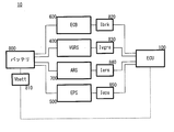
- FIG. 3 is a block diagram relating to the power supply system of the vehicle 10.
- the same reference numerals are given to the same portions as those in FIG. 1, and the description thereof will be omitted as appropriate.
- the vehicle 10 includes a battery 800.
- the battery 800 is a known in-vehicle DC 12V battery that functions as an example of the “power supply source” according to the present invention.
- the battery 800 includes a voltage sensor 810 that can detect a battery voltage value Vbatt (that is, an example of a “supply voltage” according to the present invention).
- the voltage sensor 810 is electrically connected to the ECU 100, and the detected battery voltage value Vbatt is referred to by the ECU 100 at a constant or indefinite period.
- the battery 800 is a power supply source shared by the entire chassis system including the steering system including the VGRS actuator 400, the ARS actuator 700, and the EPS actuator 500 and the ECB 600 (braking system).
- the vehicle 10 is provided with a current sensor 820 that can detect an ECB consumption current value Ibrk, which is the consumption current value of the ECB 600.
- the current sensor 820 is electrically connected to the ECU 100, and the detected ECB consumption current value Ibrk is referred to by the ECU 100 at a constant or indefinite period.
- the vehicle 10 is provided with a current sensor 830 capable of detecting the VGRS consumption current value Ivgrs which is the consumption current value of the VGRS actuator 400.
- the current sensor 830 is electrically connected to the ECU 100, and the detected VGRS consumption current value Ivgrs is referred to by the ECU 100 at a constant or indefinite period.
- the vehicle 10 includes a current sensor 840 that can detect the ARS consumption current valueInvents, which is the consumption current value of the ARS actuator 700.
- the current sensor 840 is electrically connected to the ECU 100, and the detected ARS consumption current valueInvents is referred to by the ECU 100 at a constant or indefinite period.
- the vehicle 10 is provided with a current sensor 850 that can detect an EPS consumption current value Ieps, which is a consumption current value of the EPS actuator 500.
- the current sensor 850 is electrically connected to the ECU 100, and the detected EPS consumption current value Ieps is referred to by the ECU 100 at a constant or indefinite period.
- the power supply system between the battery 800 and the chassis system is provided with a booster that boosts the DC 12V voltage supplied from the battery 800 at normal and no load to the operating voltage of each device.
- a booster that boosts the DC 12V voltage supplied from the battery 800 at normal and no load to the operating voltage of each device.
- the vehicle 10 is provided with an outside air temperature sensor and a vehicle speed sensor (not shown) so that the vehicle outside temperature temp and the vehicle speed V can be detected.
- the outside air temperature sensor and the vehicle speed sensor are electrically connected to the ECU 100, and the detected outside air temperature temp and the vehicle speed V are referred to by the ECU 100 at a constant or indefinite period.
- the vehicle 10 includes an alternator (not shown).
- the alternator includes a rotor that rotates substantially integrally with the crankshaft of the engine 200, and is configured to be able to generate three-phase AC power by rotating in the stator while the rotor is energized.
- This three-phase alternating current power is converted into direct current power by the rectifying means, and is supplied to the electrical auxiliary equipment including the various devices (ECB600, VGRS400, ARS700, and EPS500) and the battery 800.
- the generated power of the alternator is variable in accordance with the engine rotational speed NE of the engine 200 except for the operating region where the upper limit is cut by the built-in regulator. The higher the engine rotational speed NE, the larger the generated power can be obtained.
- the battery 800 is provided with a sensor capable of detecting an input current Iin input to the battery 800 during charging by the alternator and an output current Iout output from the battery 800 when power is supplied to the electrical accessories.
- the ECU 100 is configured to estimate the charge / discharge balance of the battery 800 based on the input current Iin and the output current Iout. Further, the ECU 100 is configured to estimate the power generation amount (generated power value) of the alternator based on the input current Iin or based on the engine speed NE of the engine 200.
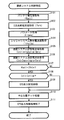
- FIG. 4 is a flowchart of the steering system control process.
- the steering system control process is a process that suppresses the deterioration of the steering feeling of the vehicle 10 when the power supply capability of the battery 800 decreases for some reason.
- the battery voltage value Vbatt is first obtained (step S101).
- the ECB consumption current value Ibrk is acquired (step S102).
- the vehicle speed V and the outside air temperature temp are acquired as parameters (step S103).
- the chassis system allowable current value Ichslim is acquired (step S104).
- the chassis system allowable current value Ichslim is an upper limit value of the current that can be used in the entire chassis system, experimentally, empirically, or theoretically set in advance.
- the vehicle speed V and the outside air temperature are stored in the ROM. It is assumed that it is stored as a fixed value according to temp.
- the chassis system allowable current value Ichslim is set higher stepwise as the vehicle speed V is higher. This is because the power consumption of the ECB 600 tends to increase as the vehicle speed increases, and it is meaningful to increase the amount by foreseeing that amount.
- the chassis system allowable current value Ichslim is set to be lower stepwise as the outside air temperature temp is higher. This is because the power consumption of the air conditioner and the like tends to increase as the outside air temperature temp increases, and it is meaningful to predict and secure the amount of air conditioner consumption.
- the chassis system allowable current value Ichslim may be set smaller than the normal temperature range in a cold temperature region or a high temperature region other than the normal temperature region sandwiched between upper and lower limits of this kind.
- the battery 800 is charged by the alternator in the operating range of the engine 200 as described above.
- the power generation amount of the alternator is estimated by the ECU 100.
- the stored chassis system allowable current value Ichslim is to be multiplied for each range of the power generation amount of the alternator divided in accordance with a standard established experimentally, empirically, or theoretically in advance.
- a coefficient (correction coefficient> 1) is prepared, and the ECU 100 is configured to correct the chassis system allowable current value Ichslim at any time by a calculation process based on the correction coefficient.
- this correction coefficient is 1, for example, when the power generation amount of the alternator belongs to the smallest category, and increases as the power generation amount increases.
- the chassis system allowable current value Ichslim in consideration of the power generation amount of such an alternator may be stored in the ROM in advance.
- the alternator power generation amount is variable according to the engine rotational speed NE, there is no practical problem even if the engine rotational speed NE is referred to instead of the alternator power generation amount.
- the steering system allowable current value Istlim is acquired (step S105).
- the steering system allowable current value Istlim is set according to the following equation (1).
- the meaning of the expression (1) is to secure a current necessary for the operation of the ECB 600 in order to ensure the safety of the vehicle among the currents usable in the entire chassis system.
- the steering system allowable current value Ichslim is variable based on the outside air temperature temp, the vehicle speed V, the engine rotational speed NE, or the alternator power generation amount as described above.
- the allowable current value Istlim is also variable for these.
- the steering system consumption current value Ist is calculated according to the following equation (2) (step S106).
- the steering system current consumption value Ist is an addition value of current consumption in the steering system, that is, the system including the EPS actuator 500, the VGRS actuator 400, and the ARS actuator 700.
- the ECU 100 determines whether or not the battery voltage value Vbatt is less than the steering system operation guarantee voltage value Vstn (step S107).
- the battery voltage value Vbatt is used as a determination index for specifying the power supply capability of the battery 800. Therefore, the steering system operation guarantee voltage value Vstn is an example of the “reference” according to the present invention.
- step S107 When the battery voltage value Vbatt is equal to or higher than the steering system operation guarantee voltage value Vstn (step S107: NO), that is, when the battery voltage value Vbatt is normal, for example, a no-load voltage equivalent value (after no-load voltage value or no-load voltage boost) Even if the voltage value is lower than the voltage value), if a value that does not cause a problem in practical operation of the steering system is secured, the process returns to step S101, and a series of processes is repeated.
- Vstn the steering system operation guarantee voltage value Vstn
- the steering system operation guarantee voltage value Vstn is the VGRS protection setting voltage value Vvgrslim set to immediately stop the operation of the VGRS actuator 400, and the EPS protection setting set to stop the operation of the EPS actuator 500 immediately.
- a value higher than the value obtained by adding the voltage drop caused by the internal resistance of the battery 800 when the entire steering system is driven at the maximum current value to the VGRS protection setting voltage value Vvgrslim, which is the higher of the voltage values Vepslim. is there.
- step S107 when the battery voltage value Vbatt is less than the steering system operation guarantee voltage value Vstn (step S107: YES), the ECU 100 determines whether or not the steering system consumption current value Ist is larger than the steering system allowable current value Istlim. (Step S108).
- the steering system consumption current value Ist is less than or equal to the steering system allowable current value Istlim (step S108: NO)
- step S110 the neutral position locking process is performed. Executed. The neutral position locking process will be described later.
- step S109 the ECU 100 executes an EPS output restriction process (step S109).
- the EPS output restriction process is to reduce the current consumption of the EPS actuator 500 so that the steering system current consumption value Ist becomes the steering system allowable current value Istlim (or a predetermined value or a value smaller by a predetermined ratio). It is processing. That is, in step S109, after obtaining a power margin that can reliably operate the VGRS actuator 400 and the ARS actuator 700 as the steering angle variable means, the assist of the driver steering torque MT by the EPS actuator 500 is continued as much as possible.
- the process proceeds to step S110.
- FIG. 5 is a flowchart of the neutral position lock process.
- the ECU 100 calculates the off-center angle ⁇ ofs for each of the front wheels and the rear wheels (step S201).
- the off-center angle is a deviation amount from the neutral position of the steering wheel with respect to the steering wheel neutral position in each of the VGRS actuator 400 and the ARS actuator 700.
- step S202 When the off-center angle ⁇ ofs is calculated, one of the VGRS actuator 400 and the ARS actuator 700 that should be prioritized is determined (step S202). Specifically, a device having a larger off-center angle ⁇ ofc calculated in step S201 is set as a priority target. This is because the larger the off-center angle ⁇ ofc, the greater the contribution to steering feeling deterioration.
- this one device to be prioritized is first set as a control target device (step S203).
- the control target device is set, the relative angle target value is set to zero, and the relative angle control of the steering angle is started (step S204).
- the relative angle of the rudder angle is the rotation angle of the lower steering shaft 14 with respect to the rotation angle of the upper steering shaft 13 that rotates in conjunction with the handle 12 if it is a front wheel (VGRS) mechanically connected to the handle 12. That is, if it is a VGRS relative angle ⁇ vgrs (that is, the actual steering angle of the front wheels is not necessarily zero) and a rear wheel (ARS) that is not mechanically connected to the handle 12, it is the rear wheel steering angle ⁇ r itself.
- VGRS front wheel
- ARS rear wheel
- step S205 it is determined whether or not the absolute value of the relative angle has decreased below the neutral determination reference value ⁇ lock (step S205). If the relative angle absolute value is greater than or equal to the neutral determination reference value (step S205: NO), the process returns to step S204.
- the neutral determination reference value ⁇ lock may be zero as one form (in this case, “less than” but “less than” is appropriate).
- the rudder angle of the wheel front wheel or rear wheel
- the rudder angle neutral point can be returned to the rudder angle neutral point, and the vehicle 10 can maintain a substantially straight traveling state within a range where there is no practical problem (that is, the deterioration of the steering feeling does not become obvious).
- Such a value can be determined experimentally, empirically or theoretically in advance.
- step S205 When the relative angle absolute value falls below the neutral determination reference value ⁇ lock (step S205: YES), the device to be controlled is locked by a lock mechanism (lock mechanism 403 or ARS lock mechanism) attached to each device (step S206). ).
- the lock completion flag FLAGlock related to the control target device is set to “1” indicating the lock completion (step S207), and the process proceeds to step S208.
- the steering angle change of the steered wheel with respect to the steering angle MA becomes unambiguous (in the case of the rear wheel, there is no change in the steered angle because it is not connected to the handle 12), and no unintended change occurs.
- condition that the relative angle absolute value has fallen below the neutral judgment reference value is used as a condition for determining whether or not the lock preparation has been completed, but the relative angle absolute value has fallen below the neutral judgment reference value. It may be determined that the preparation for the lock is completed when the elapsed time reaches a predetermined time.
- step S208 it is determined whether both the VGRS actuator 400 and the ARS actuator 700 have been locked. If one of the locks has not yet been completed (step S208: NO), the process returns to step S203, and a series of steps is performed. By this processing, relative angle control for the other device is started. When both locks are completed (step S208: YES), the neutral position locking process ends.
- step S109 when the neutral position locking process is finished, the EPS output restriction process started in step S109 is finished (step S111), and the EPS temporarily restricted for the neutral position locking of the rudder angle varying device. Normal steering torque assist by the actuator 500 is restored.
- the steering system control process is executed as described above.
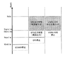
- FIG. 6 is a diagram visually representing the characteristics of the steering system control process.
- the vertical axis represents the battery voltage value Vbatt.
- Vbatt falls below the steering system operation guarantee voltage value Vstn, in the voltage region where the battery voltage value Vbatt is equal to or higher than the VGRS protection set voltage value Vvgrslim (or the ARS protection set voltage value Varslim), the hatched display portion shown in the figure.
- the EPS output restriction process and the neutral position lock process of the VGRS actuator 500 and the ARS actuator 700 are executed.
- the current consumption of the EPS actuator 500 which should be prioritized for operation, is temporarily limited, and the current is transferred within the frame of the current allowed for the steering system.
- the neutral position lock of the angle variable means can be completed. Therefore, when the steering wheel 12 returns to the neutral position, the deflection of the vehicle due to a change in the steering angle remaining on the front wheels or the rear wheels, or the deflection of the vehicle due to an unintended steering angle change while the operation of the steering wheel 12 continues. Therefore, the deterioration of the steering feeling caused by these can be suitably suppressed.
- the VGRS actuator 400 and the ARS actuator 700 are immediately stopped, and the EPS actuator 500 maintains the assist at the minimum output. Is planned. Further, when the battery voltage value Vbatt falls below the EPS protection set voltage value Vepslim, the steering torque assist by the EPS actuator 500 is immediately stopped. When the battery voltage value Vbatt further decreases to a level lower than the ECB protection set voltage Vbrklim, the ECB 600 is immediately stopped.
- the protection setting voltage is set to be lower as the apparatus that contributes to the traveling safety of the vehicle 10 is maintained, and the control can be maintained as much as possible. For this reason, the safety of the vehicle 10 is suitably ensured.
- the battery voltage value Vbatt is used as a determination index for specifying the power supply capability of the battery 800.
- the determination index for determining the power supply capability of the battery 800 is not necessarily limited to the battery voltage Vbatt.
- the battery 800 is charged by the alternator as described above in the operating range of the engine 200.
- charge / discharge balance of the battery 800 when the charge / discharge balance of the battery 800 is inclined to the positive side (that is, charge amount> discharge amount), it can be considered that the battery 800 has excess power, and conversely, When the charge / discharge balance is inclined to the negative side (that is, charge amount ⁇ discharge amount), it can be considered that the power supply capability of the battery 800 is reduced.
- the charge / discharge balance of the battery 800 can be an effective reference factor.
- a reference value that is, another example of the “reference” according to the present invention
- This reference value may be, for example, the zero point, a negative value near the zero point (in this case, the operation permission area of the steering system is expanded), or a positive value near the zero point. (In this case, it is safer from the viewpoint of system protection).
- the present invention is not limited to the above-described embodiments, and can be appropriately changed without departing from the gist or concept of the invention that can be read from the claims and the entire specification, and vehicle steering control with such changes is possible.
- the apparatus is also included in the technical scope of the present invention.
- the present invention can be used for, for example, a vehicle having a function of causing the vehicle to follow a target travel path.
Landscapes
- Engineering & Computer Science (AREA)
- Chemical & Material Sciences (AREA)
- Combustion & Propulsion (AREA)
- Transportation (AREA)
- Mechanical Engineering (AREA)
- Physics & Mathematics (AREA)
- Mathematical Physics (AREA)
- Theoretical Computer Science (AREA)
- Steering Control In Accordance With Driving Conditions (AREA)
- Power Steering Mechanism (AREA)
- Steering-Linkage Mechanisms And Four-Wheel Steering (AREA)
- Electric Propulsion And Braking For Vehicles (AREA)
Abstract
Description
以下、適宜図面を参照して本発明の車両の制御装置に係る各種実施形態について説明する。
<実施形態の構成>
始めに、図1を参照して、本発明の一実施形態に係る車両10の構成について説明する。ここに、図1は、車両10の基本的な構成を概念的に表してなる概略構成図である。
<実施形態の動作>
続いて、本実施形態の動作について説明する。
即ち、(1)式の意味するところは、シャシーシステム全体で使用可能な電流のうち、車両の安全性を確保するためにECB600の動作に必要な電流を確保する点にある。尚、上記(1)の関係からして、上述したように外気温temp、車速V及び機関回転速度NE又はオルタネータ発電量に基づいてシャシーシステム許容電流値Ichslimが可変であることに伴い、操舵システム許容電流値Istlimもまたこれらに対して可変となる。
即ち、操舵システム消費電流値Istとは、操舵システム、即ち、EPSアクチュエータ500と、VGRSアクチュエータ400とARSアクチュエータ700とからなるシステムにおける消費電流の加算値である。
Claims (8)
- ハンドルの回転角たる操舵角と操舵輪の舵角との関係を変化させることが可能な舵角可変手段及びドライバ操舵トルクをアシスト可能な操舵トルクアシスト手段を少なくとも含む操舵システムと、前記操舵システムに対し電力を供給する電力供給源とを備えた車両における操舵制御装置であって、
前記電力供給源における前記電力の供給能力を特定する供給能力特定手段と、
前記操舵システムの消費電流値を特定する消費電流特定手段と、
前記特定された供給能力が基準に対して低下した場合において、前記特定された消費電流値が前記操舵システムの最大許容電流値より大きい場合に、前記操舵トルクアシスト手段の電流消費を制限する制限手段と、
前記操舵トルクアシスト手段の電流消費が制限された状態において、前記ハンドルの中立位置と前記操舵輪の中立位置とが一致するように前記舵角可変手段を制御する制御手段と
を具備することを特徴とする車両の操舵制御装置。 - 前記供給能力特定手段は、前記電力供給源の供給電圧値に基づいて前記供給能力を特定する
ことを特徴とする請求の範囲第1項に記載の車両の操舵制御装置。 - 前記供給能力特定手段は、前記電力供給源の充放電収支に基づいて前記供給能力を特定する
ことを特徴とする請求の範囲第1項に記載の車両の操舵制御装置。 - 前記舵角可変手段は、前記関係を一義的に固定するロック機構を備えており、
前記制御手段は、前記ハンドルの中立位置と前記操舵輪の中立位置とを一致させた後に、前記関係が一義的固定されるように前記ロック機構を制御する
ことを特徴とする請求の範囲第1項に記載の車両の操舵制御装置。 - 前記制限手段は、前記最大許容電流値に応じて前記電流消費を制限する
ことを特徴とする請求の範囲第1項又は第2項に記載の車両の操舵制御装置。 - 前記舵角可変手段は、前輪を前記操舵輪とする前輪舵角可変手段と、後輪を前記操舵輪とする後輪舵角可変手段とを含み、
前記制御手段は、前記前輪舵角可変手段と前記後輪舵角可変手段とのうち、前記ハンドルの中立位置に対する前記操舵輪における前記操舵輪の中立位置からのずれ量が大きい一方を優先して制御する
ことを特徴とする請求の範囲第1項に記載の車両の操舵制御装置。 - 前記車両は、内燃機関及びオルタネータを備え、
前記最大許容電流値は、車速、外気温、前記内燃機関の機関回転速度又は前記オルタネータの発電量に応じて可変である
ことを特徴とする請求の範囲第1項に記載の車両の操舵制御装置。 - 前記車両は、前記電力供給源を前記操舵システムと共有する制動システムを備え、
前記最大許容電流値は、前記操舵システムと前記制動システムを少なくとも含むシャシーシステム全体で使用可能な電流値から前記制動システムが使用する電流値を差し引いた値である
ことを特徴とする請求の範囲第1項に記載の車両の操舵制御装置。
Priority Applications (5)
| Application Number | Priority Date | Filing Date | Title |
|---|---|---|---|
| DE112011105292.8T DE112011105292B4 (de) | 2011-06-01 | 2011-06-01 | Fahrzeuglenksteuervorrichtung |
| PCT/JP2011/062632 WO2012164706A1 (ja) | 2011-06-01 | 2011-06-01 | 車両の操舵制御装置 |
| CN201180019403.5A CN102917941B (zh) | 2011-06-01 | 2011-06-01 | 车辆的转向控制装置 |
| US13/811,697 US9321480B2 (en) | 2011-06-01 | 2011-06-01 | Vehicle steering control apparatus |
| JP2012544786A JP5408363B2 (ja) | 2011-06-01 | 2011-06-01 | 車両の操舵制御装置 |
Applications Claiming Priority (1)
| Application Number | Priority Date | Filing Date | Title |
|---|---|---|---|
| PCT/JP2011/062632 WO2012164706A1 (ja) | 2011-06-01 | 2011-06-01 | 車両の操舵制御装置 |
Publications (1)
| Publication Number | Publication Date |
|---|---|
| WO2012164706A1 true WO2012164706A1 (ja) | 2012-12-06 |
Family
ID=47258591
Family Applications (1)
| Application Number | Title | Priority Date | Filing Date |
|---|---|---|---|
| PCT/JP2011/062632 Ceased WO2012164706A1 (ja) | 2011-06-01 | 2011-06-01 | 車両の操舵制御装置 |
Country Status (5)
| Country | Link |
|---|---|
| US (1) | US9321480B2 (ja) |
| JP (1) | JP5408363B2 (ja) |
| CN (1) | CN102917941B (ja) |
| DE (1) | DE112011105292B4 (ja) |
| WO (1) | WO2012164706A1 (ja) |
Families Citing this family (38)
| Publication number | Priority date | Publication date | Assignee | Title |
|---|---|---|---|---|
| EP2463497A1 (en) * | 2010-12-10 | 2012-06-13 | Perkins Engines Company Limited | Turbocharger control |
| US9321480B2 (en) * | 2011-06-01 | 2016-04-26 | Toyota Jidosha Kabushiki Kaisha | Vehicle steering control apparatus |
| US9205717B2 (en) | 2012-11-07 | 2015-12-08 | Polaris Industries Inc. | Vehicle having suspension with continuous damping control |
| DE112012006826T5 (de) * | 2012-12-28 | 2015-05-21 | Toyota Jidosha Kabushiki Kaisha | Fahrzeugsteuerungsgerät |
| DE102014201107B4 (de) * | 2013-02-06 | 2016-02-11 | Ford Global Technologies, Llc | Verfahren und Vorrichtung zur Beschränkung eines unterstützenden Lenkmoments in einem Lenksystem mit elektronischer Lenkunterstützung |
| DE112013006873B4 (de) * | 2013-03-27 | 2020-03-19 | Toyota Jidosha Kabushiki Kaisha | Fahrzeuglenksteuervorrichtung |
| DE102013220921A1 (de) * | 2013-10-16 | 2015-04-16 | Zf Friedrichshafen Ag | Lenkwinkelvorrichtung für ein Kraftfahrzeug |
| JP6156077B2 (ja) * | 2013-11-08 | 2017-07-05 | トヨタ自動車株式会社 | 車両制御装置 |
| CN103646591B (zh) * | 2013-12-16 | 2016-02-10 | 北京经纬恒润科技有限公司 | 一种传感器零点学习方法和系统 |
| CN107406094B (zh) | 2014-10-31 | 2020-04-14 | 北极星工业有限公司 | 用于控制车辆的系统和方法 |
| JP6376352B2 (ja) * | 2015-08-07 | 2018-08-22 | トヨタ自動車株式会社 | 車両の走行制御装置 |
| CN106184350B (zh) * | 2016-07-08 | 2018-11-09 | 南京航空航天大学 | 一种多模式的四轮转向系统及转向模式控制方法 |
| JP6631426B2 (ja) * | 2016-07-08 | 2020-01-15 | マツダ株式会社 | 車載通信システム |
| CN106564527B (zh) * | 2016-10-28 | 2019-09-13 | 西安合众思壮导航技术有限公司 | 一种车辆液压转向系统的控制方法 |
| CA3043481C (en) | 2016-11-18 | 2022-07-26 | Polaris Industries Inc. | Vehicle having adjustable suspension |
| US10406884B2 (en) | 2017-06-09 | 2019-09-10 | Polaris Industries Inc. | Adjustable vehicle suspension system |
| WO2019058230A1 (en) | 2017-09-19 | 2019-03-28 | Bombardier Recreational Products Inc. | CONTROL OF LIMITED SLIP DIFFERENTIAL BASED ON MOTOR TORQUE |
| RU2768680C2 (ru) | 2017-09-19 | 2022-03-24 | Бомбардье Рекриэйшенел Продактс Инк. | Управление дифференциалом ограниченного проскальзывания на основе положения средства управления ускорителем |
| WO2019058227A1 (en) * | 2017-09-19 | 2019-03-28 | Bombardier Recreational Products Inc. | CONTROL OF A SELF-LOCKING DIFFERENTIAL BASED ON A STEERING ANGLE OF A VEHICLE |
| CN111094797B (zh) | 2017-09-19 | 2023-10-27 | 庞巴迪动力产品公司 | 针对湿滑驾驶条件而优化的限滑差速器的控制 |
| KR102458757B1 (ko) | 2017-11-29 | 2022-10-26 | 현대자동차주식회사 | 리어 휠 스티어링 제어시스템 및 이를 이용한 제어방법 |
| WO2019142319A1 (ja) | 2018-01-19 | 2019-07-25 | 株式会社ショーワ | 操舵装置 |
| DE102018202905A1 (de) * | 2018-02-27 | 2019-03-07 | Audi Ag | Querführungsverfahren und -system für ein Fahrzeug |
| DE102018124244A1 (de) * | 2018-10-01 | 2020-04-02 | Bayerische Motoren Werke Aktiengesellschaft | Verfahren zum Betrieb einer Hinterachslenkung eines zweispurigen Fahrzeuges |
| US10987987B2 (en) | 2018-11-21 | 2021-04-27 | Polaris Industries Inc. | Vehicle having adjustable compression and rebound damping |
| JP7052745B2 (ja) * | 2019-01-25 | 2022-04-12 | トヨタ自動車株式会社 | 車両制御システム |
| KR102610780B1 (ko) * | 2019-02-12 | 2023-12-06 | 에이치엘만도 주식회사 | 조향 제어 장치 및 조향 제어 방법 |
| US11975771B2 (en) * | 2019-10-31 | 2024-05-07 | Nsk Ltd. | Vehicle steering device |
| JP7234962B2 (ja) * | 2020-02-11 | 2023-03-08 | トヨタ自動車株式会社 | 転舵装置およびそれが設けられたステアリングシステム |
| US12397878B2 (en) | 2020-05-20 | 2025-08-26 | Polaris Industries Inc. | Systems and methods of adjustable suspensions for off-road recreational vehicles |
| MX2022015902A (es) | 2020-07-17 | 2023-01-24 | Polaris Inc | Suspensiones ajustables y operacion de vehiculo para vehiculos recreativos todoterreno. |
| JP7637502B2 (ja) * | 2020-12-02 | 2025-02-28 | 株式会社ジェイテクト | 電源システム |
| DE102021202285A1 (de) * | 2021-03-09 | 2022-09-15 | Robert Bosch Gesellschaft mit beschränkter Haftung | Vorrichtung und Verfahren zur Beeinflussung eines Fahrzeugverhaltens |
| JP7063428B1 (ja) * | 2021-03-12 | 2022-05-09 | 日本精工株式会社 | 転舵装置のエンド位置の検出装置、検出方法、およびプログラム |
| JP7684126B2 (ja) * | 2021-07-21 | 2025-05-27 | 株式会社ジェイテクト | 操舵装置 |
| JP7685422B2 (ja) * | 2021-10-26 | 2025-05-29 | 株式会社ジェイテクト | 操舵制御装置、車両用電源システムおよび車両 |
| US11686379B1 (en) | 2022-01-27 | 2023-06-27 | Polestar Performance Ab | Controllable speed differential |
| US20260084507A1 (en) * | 2024-09-24 | 2026-03-26 | Dana Automotive Systems Group, Llc | Electric axle and electric axle product line |
Citations (3)
| Publication number | Priority date | Publication date | Assignee | Title |
|---|---|---|---|---|
| JP2001287657A (ja) * | 2000-04-05 | 2001-10-16 | Honda Motor Co Ltd | 可変舵角比操舵装置及び電動パワーステアリング装置を有する車両 |
| JP2008290664A (ja) * | 2007-05-28 | 2008-12-04 | Nsk Ltd | 電動パワーステアリング装置 |
| JP2010018177A (ja) * | 2008-07-11 | 2010-01-28 | Toyota Motor Corp | 車両制御装置 |
Family Cites Families (21)
| Publication number | Priority date | Publication date | Assignee | Title |
|---|---|---|---|---|
| JP3003228B2 (ja) * | 1991-01-14 | 2000-01-24 | 株式会社デンソー | 車両の舵角制御装置 |
| US6250419B1 (en) * | 2000-02-16 | 2001-06-26 | Ford Global Technologies, Inc. | Vehicle electric power assist steering system and method using H-infinity control |
| DE10323042A1 (de) | 2002-05-24 | 2004-02-26 | Continental Teves Ag & Co. Ohg | Überlagerungsgetriebe für eine Überlagerungslenkung |
| JP2005526661A (ja) | 2002-05-24 | 2005-09-08 | コンティネンタル・テーベス・アクチエンゲゼルシヤフト・ウント・コンパニー・オッフェネ・ハンデルスゲゼルシヤフト | オーバーライド操舵システム用オーバーライド装置 |
| JP3960266B2 (ja) * | 2003-05-28 | 2007-08-15 | トヨタ自動車株式会社 | 車輌用操舵制御装置 |
| JP4517734B2 (ja) | 2004-06-03 | 2010-08-04 | 日本精工株式会社 | 電動パワーステアリング装置 |
| JP4404700B2 (ja) * | 2004-06-24 | 2010-01-27 | 三菱電機株式会社 | 車両用電動油圧パワーステアリング装置 |
| JP4682639B2 (ja) * | 2005-02-15 | 2011-05-11 | 日産自動車株式会社 | 操舵制御装置 |
| JP4868397B2 (ja) * | 2006-02-09 | 2012-02-01 | 国立大学法人 名古屋工業大学 | 電動可変ギア伝達装置と電動パワーステアリング装置の制御装置 |
| WO2007129750A1 (ja) * | 2006-05-10 | 2007-11-15 | Toyota Jidosha Kabushiki Kaisha | 車両転舵制御装置 |
| US20080066991A1 (en) * | 2006-09-15 | 2008-03-20 | Denso Corporation | On-vehicle control apparatus powered by on-vehicle battery |
| JP4952931B2 (ja) * | 2007-08-30 | 2012-06-13 | トヨタ自動車株式会社 | ステアリング装置 |
| EP2216234B1 (en) * | 2007-11-19 | 2016-04-13 | Toyota Jidosha Kabushiki Kaisha | Vehicle steering control device |
| JP5029312B2 (ja) * | 2007-11-20 | 2012-09-19 | 株式会社ジェイテクト | 電動パワーステアリング装置 |
| CN102232031B (zh) * | 2009-01-22 | 2013-09-18 | 丰田自动车株式会社 | 电动动力转向装置 |
| JP2010208490A (ja) | 2009-03-10 | 2010-09-24 | Toyota Motor Corp | 車両用操舵制御装置 |
| DE102009012932A1 (de) | 2009-03-12 | 2010-09-23 | Audi Ag | Verfahren zum Betreiben eines Lenkungssystems in einem Kraftfahrzeug |
| JP5429290B2 (ja) * | 2009-09-11 | 2014-02-26 | トヨタ自動車株式会社 | 後輪操舵装置の制御装置 |
| EP2555415A1 (en) * | 2010-03-29 | 2013-02-06 | Toyota Jidosha Kabushiki Kaisha | Electric power steering system |
| JP5043981B2 (ja) * | 2010-04-26 | 2012-10-10 | 三菱電機株式会社 | 電動パワーステアリング装置 |
| US9321480B2 (en) * | 2011-06-01 | 2016-04-26 | Toyota Jidosha Kabushiki Kaisha | Vehicle steering control apparatus |
-
2011
- 2011-06-01 US US13/811,697 patent/US9321480B2/en not_active Expired - Fee Related
- 2011-06-01 WO PCT/JP2011/062632 patent/WO2012164706A1/ja not_active Ceased
- 2011-06-01 JP JP2012544786A patent/JP5408363B2/ja not_active Expired - Fee Related
- 2011-06-01 DE DE112011105292.8T patent/DE112011105292B4/de not_active Expired - Fee Related
- 2011-06-01 CN CN201180019403.5A patent/CN102917941B/zh not_active Expired - Fee Related
Patent Citations (3)
| Publication number | Priority date | Publication date | Assignee | Title |
|---|---|---|---|---|
| JP2001287657A (ja) * | 2000-04-05 | 2001-10-16 | Honda Motor Co Ltd | 可変舵角比操舵装置及び電動パワーステアリング装置を有する車両 |
| JP2008290664A (ja) * | 2007-05-28 | 2008-12-04 | Nsk Ltd | 電動パワーステアリング装置 |
| JP2010018177A (ja) * | 2008-07-11 | 2010-01-28 | Toyota Motor Corp | 車両制御装置 |
Also Published As
| Publication number | Publication date |
|---|---|
| JP5408363B2 (ja) | 2014-02-05 |
| DE112011105292B4 (de) | 2018-10-31 |
| US20130124045A1 (en) | 2013-05-16 |
| CN102917941A (zh) | 2013-02-06 |
| CN102917941B (zh) | 2014-11-05 |
| JPWO2012164706A1 (ja) | 2014-07-31 |
| US9321480B2 (en) | 2016-04-26 |
| DE112011105292T5 (de) | 2014-03-13 |
Similar Documents
| Publication | Publication Date | Title |
|---|---|---|
| JP5408363B2 (ja) | 車両の操舵制御装置 | |
| CN103237707B (zh) | 车辆的运动控制装置 | |
| JP5516498B2 (ja) | 車両の挙動制御装置 | |
| JP4379406B2 (ja) | 車両の駆動力配分制御装置 | |
| CN103223973B (zh) | 车辆及操舵装置 | |
| US8989964B2 (en) | Vehicle speed control device | |
| JP5534019B2 (ja) | 車両制御装置 | |
| KR102122332B1 (ko) | 차량 | |
| JP2004104991A (ja) | 回生制動を持つ車両の独立制動及び操縦性の制御方法及びシステム | |
| EP2556990B1 (en) | A wheel drive architecture for electric vehicles | |
| US20200361525A1 (en) | Steering apparatus | |
| WO2022024753A1 (ja) | 電動車両の駆動制御装置 | |
| JP5691459B2 (ja) | 車両の挙動制御装置 | |
| JP2006256454A (ja) | 車両のトルク配分制御装置 | |
| JP2011201366A (ja) | 車両の制御装置 | |
| JP5907198B2 (ja) | 車両制御装置 | |
| JP2012136090A (ja) | 車両制御装置 | |
| JP2009220617A (ja) | 操舵装置 | |
| JP2011207314A (ja) | 車両の制御装置 | |
| JP2012166715A (ja) | 車両の走行制御装置 | |
| JP2012111346A (ja) | 車両制御装置 | |
| JP2011207310A (ja) | 操舵制御装置 | |
| JP5625801B2 (ja) | 車両挙動制御装置 | |
| JP4935022B2 (ja) | 車両の左右トルク配分制御装置 | |
| JP4852931B2 (ja) | 車両の左右トルク配分制御装置 |
Legal Events
| Date | Code | Title | Description |
|---|---|---|---|
| WWE | Wipo information: entry into national phase |
Ref document number: 201180019403.5 Country of ref document: CN |
|
| ENP | Entry into the national phase |
Ref document number: 2012544786 Country of ref document: JP Kind code of ref document: A |
|
| 121 | Ep: the epo has been informed by wipo that ep was designated in this application |
Ref document number: 11866807 Country of ref document: EP Kind code of ref document: A1 |
|
| WWE | Wipo information: entry into national phase |
Ref document number: 13811697 Country of ref document: US |
|
| WWE | Wipo information: entry into national phase |
Ref document number: 1120111052928 Country of ref document: DE Ref document number: 112011105292 Country of ref document: DE |
|
| 122 | Ep: pct application non-entry in european phase |
Ref document number: 11866807 Country of ref document: EP Kind code of ref document: A1 |