WO2012164630A1 - Système de stockage d'électricité - Google Patents
Système de stockage d'électricité Download PDFInfo
- Publication number
- WO2012164630A1 WO2012164630A1 PCT/JP2011/003151 JP2011003151W WO2012164630A1 WO 2012164630 A1 WO2012164630 A1 WO 2012164630A1 JP 2011003151 W JP2011003151 W JP 2011003151W WO 2012164630 A1 WO2012164630 A1 WO 2012164630A1
- Authority
- WO
- WIPO (PCT)
- Prior art keywords
- power storage
- storage device
- relay
- state
- controller
- Prior art date
Links
Images


Classifications
-
- B—PERFORMING OPERATIONS; TRANSPORTING
- B60—VEHICLES IN GENERAL
- B60L—PROPULSION OF ELECTRICALLY-PROPELLED VEHICLES; SUPPLYING ELECTRIC POWER FOR AUXILIARY EQUIPMENT OF ELECTRICALLY-PROPELLED VEHICLES; ELECTRODYNAMIC BRAKE SYSTEMS FOR VEHICLES IN GENERAL; MAGNETIC SUSPENSION OR LEVITATION FOR VEHICLES; MONITORING OPERATING VARIABLES OF ELECTRICALLY-PROPELLED VEHICLES; ELECTRIC SAFETY DEVICES FOR ELECTRICALLY-PROPELLED VEHICLES
- B60L58/00—Methods or circuit arrangements for monitoring or controlling batteries or fuel cells, specially adapted for electric vehicles
- B60L58/10—Methods or circuit arrangements for monitoring or controlling batteries or fuel cells, specially adapted for electric vehicles for monitoring or controlling batteries
- B60L58/12—Methods or circuit arrangements for monitoring or controlling batteries or fuel cells, specially adapted for electric vehicles for monitoring or controlling batteries responding to state of charge [SoC]
-
- B—PERFORMING OPERATIONS; TRANSPORTING
- B60—VEHICLES IN GENERAL
- B60L—PROPULSION OF ELECTRICALLY-PROPELLED VEHICLES; SUPPLYING ELECTRIC POWER FOR AUXILIARY EQUIPMENT OF ELECTRICALLY-PROPELLED VEHICLES; ELECTRODYNAMIC BRAKE SYSTEMS FOR VEHICLES IN GENERAL; MAGNETIC SUSPENSION OR LEVITATION FOR VEHICLES; MONITORING OPERATING VARIABLES OF ELECTRICALLY-PROPELLED VEHICLES; ELECTRIC SAFETY DEVICES FOR ELECTRICALLY-PROPELLED VEHICLES
- B60L3/00—Electric devices on electrically-propelled vehicles for safety purposes; Monitoring operating variables, e.g. speed, deceleration or energy consumption
- B60L3/0023—Detecting, eliminating, remedying or compensating for drive train abnormalities, e.g. failures within the drive train
- B60L3/0046—Detecting, eliminating, remedying or compensating for drive train abnormalities, e.g. failures within the drive train relating to electric energy storage systems, e.g. batteries or capacitors
-
- B—PERFORMING OPERATIONS; TRANSPORTING
- B60—VEHICLES IN GENERAL
- B60L—PROPULSION OF ELECTRICALLY-PROPELLED VEHICLES; SUPPLYING ELECTRIC POWER FOR AUXILIARY EQUIPMENT OF ELECTRICALLY-PROPELLED VEHICLES; ELECTRODYNAMIC BRAKE SYSTEMS FOR VEHICLES IN GENERAL; MAGNETIC SUSPENSION OR LEVITATION FOR VEHICLES; MONITORING OPERATING VARIABLES OF ELECTRICALLY-PROPELLED VEHICLES; ELECTRIC SAFETY DEVICES FOR ELECTRICALLY-PROPELLED VEHICLES
- B60L50/00—Electric propulsion with power supplied within the vehicle
- B60L50/50—Electric propulsion with power supplied within the vehicle using propulsion power supplied by batteries or fuel cells
- B60L50/51—Electric propulsion with power supplied within the vehicle using propulsion power supplied by batteries or fuel cells characterised by AC-motors
-
- B—PERFORMING OPERATIONS; TRANSPORTING
- B60—VEHICLES IN GENERAL
- B60L—PROPULSION OF ELECTRICALLY-PROPELLED VEHICLES; SUPPLYING ELECTRIC POWER FOR AUXILIARY EQUIPMENT OF ELECTRICALLY-PROPELLED VEHICLES; ELECTRODYNAMIC BRAKE SYSTEMS FOR VEHICLES IN GENERAL; MAGNETIC SUSPENSION OR LEVITATION FOR VEHICLES; MONITORING OPERATING VARIABLES OF ELECTRICALLY-PROPELLED VEHICLES; ELECTRIC SAFETY DEVICES FOR ELECTRICALLY-PROPELLED VEHICLES
- B60L58/00—Methods or circuit arrangements for monitoring or controlling batteries or fuel cells, specially adapted for electric vehicles
- B60L58/10—Methods or circuit arrangements for monitoring or controlling batteries or fuel cells, specially adapted for electric vehicles for monitoring or controlling batteries
- B60L58/18—Methods or circuit arrangements for monitoring or controlling batteries or fuel cells, specially adapted for electric vehicles for monitoring or controlling batteries of two or more battery modules
- B60L58/21—Methods or circuit arrangements for monitoring or controlling batteries or fuel cells, specially adapted for electric vehicles for monitoring or controlling batteries of two or more battery modules having the same nominal voltage
-
- B—PERFORMING OPERATIONS; TRANSPORTING
- B60—VEHICLES IN GENERAL
- B60L—PROPULSION OF ELECTRICALLY-PROPELLED VEHICLES; SUPPLYING ELECTRIC POWER FOR AUXILIARY EQUIPMENT OF ELECTRICALLY-PROPELLED VEHICLES; ELECTRODYNAMIC BRAKE SYSTEMS FOR VEHICLES IN GENERAL; MAGNETIC SUSPENSION OR LEVITATION FOR VEHICLES; MONITORING OPERATING VARIABLES OF ELECTRICALLY-PROPELLED VEHICLES; ELECTRIC SAFETY DEVICES FOR ELECTRICALLY-PROPELLED VEHICLES
- B60L58/00—Methods or circuit arrangements for monitoring or controlling batteries or fuel cells, specially adapted for electric vehicles
- B60L58/10—Methods or circuit arrangements for monitoring or controlling batteries or fuel cells, specially adapted for electric vehicles for monitoring or controlling batteries
- B60L58/18—Methods or circuit arrangements for monitoring or controlling batteries or fuel cells, specially adapted for electric vehicles for monitoring or controlling batteries of two or more battery modules
- B60L58/22—Balancing the charge of battery modules
-
- H—ELECTRICITY
- H02—GENERATION; CONVERSION OR DISTRIBUTION OF ELECTRIC POWER
- H02J—CIRCUIT ARRANGEMENTS OR SYSTEMS FOR SUPPLYING OR DISTRIBUTING ELECTRIC POWER; SYSTEMS FOR STORING ELECTRIC ENERGY
- H02J7/00—Circuit arrangements for charging or depolarising batteries or for supplying loads from batteries
- H02J7/0013—Circuit arrangements for charging or depolarising batteries or for supplying loads from batteries acting upon several batteries simultaneously or sequentially
- H02J7/0014—Circuits for equalisation of charge between batteries
- H02J7/0016—Circuits for equalisation of charge between batteries using shunting, discharge or bypass circuits
-
- Y—GENERAL TAGGING OF NEW TECHNOLOGICAL DEVELOPMENTS; GENERAL TAGGING OF CROSS-SECTIONAL TECHNOLOGIES SPANNING OVER SEVERAL SECTIONS OF THE IPC; TECHNICAL SUBJECTS COVERED BY FORMER USPC CROSS-REFERENCE ART COLLECTIONS [XRACs] AND DIGESTS
- Y02—TECHNOLOGIES OR APPLICATIONS FOR MITIGATION OR ADAPTATION AGAINST CLIMATE CHANGE
- Y02T—CLIMATE CHANGE MITIGATION TECHNOLOGIES RELATED TO TRANSPORTATION
- Y02T10/00—Road transport of goods or passengers
- Y02T10/60—Other road transportation technologies with climate change mitigation effect
- Y02T10/70—Energy storage systems for electromobility, e.g. batteries
Definitions
- the present invention relates to a power storage system in which a first power storage device and a second power storage device are connected in parallel.
- a difference in electromotive voltage may occur between the two assembled batteries.
- a circulating current inrush current
- the relay provided in each assembled battery may be deteriorated.
- the power storage system of the present invention includes a first power storage device and a second power storage device that perform charging and discharging, a first relay and a second relay, and a controller.
- the first relay switches between an on state that allows charging / discharging of the first power storage device and an off state that prohibits charging / discharging of the first power storage device.
- the second relay switches between an on state that allows charging / discharging of the second power storage device and an off state that prohibits charging / discharging of the second power storage device.
- the first power storage device and the first relay, and the second power storage device and the second relay are connected in parallel.
- the controller switches the first relay and the second relay from the on state to the off state after allowing the circulating current flowing between the first power storage device and the second power storage device.
- the controller can allow the circulating current until the difference in electromotive voltage between the first power storage device and the second power storage device is equal to or lower than the rated voltage of each relay. Thereby, it can suppress that the difference of an electromotive voltage exceeds the rated voltage of a relay, and degradation of a relay can be prevented.
- a third relay can be provided in the power storage system.
- the third relay switches between an on state that allows charging / discharging of the first power storage device and the second power storage device and an off state that prohibits charging / discharging of the first power storage device and the second power storage device.
- the controller can switch the first relay and the second relay from the on state to the off state after switching the third relay from the on state to the off state. If the third relay is switched to the off state, the first power storage device and the second power storage device can be disconnected from the connection with the load. At this time, the first relay and the second relay remain in the ON state, and a circulating current flows between the first power storage device and the second power storage device.
- a current sensor for detecting circulating current can be provided.
- the controller can switch the first relay and the second relay from the on state to the off state in response to the current value detected by the current sensor being equal to or less than the threshold value. By reducing the circulating current, the difference in electromotive voltage between the first power storage device and the second power storage device can be made equal to or lower than the rated voltage of the relay.
- the threshold value can be determined based on the following formula (I).
- Ith Vr / (R1 + R2) (I)
- Ith is a threshold value
- Vr is a rated voltage of the relay
- R1 and R2 are internal resistances of the first power storage device and the second power storage device, respectively.
- the internal resistances R1 and R2 can be the maximum value of the internal resistance that changes in each power storage device. Since the internal resistance changes, setting the threshold value Ith using the maximum value of the change range as the internal resistances R1 and R2, it is easy to ensure a state in which the difference in electromotive voltage is less than or equal to the rated voltage of the relay.
- the internal resistances R1, R2 can be changed according to at least one of the temperature and SOC of each power storage device. Since the internal resistances R1 and R2 may depend on the temperature and the SOC, the internal resistances R1 and R2 can be changed according to the temperature and the SOC. Thereby, the threshold value Ith corresponding to the actual internal resistances R1 and R2 can be set.
- the time during which the circulating current flows until the difference in electromotive voltage becomes less than the rated voltage of the relay can be determined in advance, and this time (set time) can be stored in the memory.
- the controller can switch the first relay and the second relay from the on state to the off state after the set time has elapsed since the circulation current began to flow. If the set time described above is determined in advance, the first relay and the second relay can be turned off only by counting the time.
- the set time can be calculated from, for example, the maximum value of the difference in electromotive voltage and the maximum value of the difference in internal resistance between the first power storage device and the second power storage device. If the maximum value of the difference between the electromotive voltages and the maximum value of the difference between the internal resistances are determined, the time until the difference between the electromotive voltages becomes less than the rated voltage of the relay can be calculated.
- the first power storage device a power storage device that can be charged and discharged with a larger current than the second power storage device can be used.
- the second power storage device can be a power storage device having a larger storage capacity than the first power storage device.
- Each power storage device can output energy used to travel the vehicle.
- the vehicle can be driven by using at least one of the first power storage device and the second power storage device.
- an assembled battery in which a plurality of single cells are connected in series can be used as each power storage device.
- the first relay and the second relay after flowing a circulating current between the first power storage device and the second power storage device, the first relay and the second relay are switched from the on state to the off state. Thereby, the difference in electromotive voltage between the first power storage device and the second power storage device can be reduced. Even if the first relay and the second relay are switched on again, the circulating current (inrush current) flowing between the first power storage device and the second power storage device can be suppressed, and the relay current (inrush current) is reduced. Deterioration can be suppressed.
- Example 1 It is a figure which shows the structure of the battery system which is Example 1.
- FIG. 1 is a diagram showing the configuration of the battery system of this example.
- the battery system of the present embodiment can be mounted on a vehicle.
- the battery system of this embodiment has two assembled batteries 10 and 20 connected in parallel.
- the assembled battery (corresponding to the first power storage device) 10 includes a plurality of unit cells 11 connected in series.
- the assembled battery (corresponding to the second power storage device) 20 includes a plurality of unit cells 21 connected in series.
- secondary batteries such as nickel metal hydride batteries and lithium ion batteries can be used.
- An electric double layer capacitor can be used instead of the secondary battery.
- the number of the cells 11 and 21 constituting the assembled batteries 10 and 20 can be set as appropriate based on the required output. Moreover, at least one of the assembled batteries 10 and 20 may include the single cells 11 and 21 connected in parallel. Note that the single cells 11 and 21 may be used one by one, and the single cells 11 and 21 may be connected in parallel.
- the assembled batteries 10 and 20 have service plugs (current breakers) 12 and 22, respectively.
- the service plugs 12 and 22 are used to cut off the current flowing through the assembled batteries 10 and 20.
- the current paths in the assembled batteries 10 and 20 can be interrupted by removing the service plugs 12 and 22 from the assembled batteries 10 and 20.
- the assembled batteries 10 and 20 have fuses 13 and 23.
- the voltage sensor 31 detects the voltage (total voltage) between the terminals of the assembled battery 10 and outputs the detection result to the controller 40.
- the voltage sensor 32 detects the inter-terminal voltage (total voltage) of the assembled battery 20 and outputs the detection result to the controller 40.
- the controller 40 includes a memory 40a. In the present embodiment, the memory 40 a is built in the controller 40, but the memory 40 a may be provided outside the controller 40.
- the assembled battery 10 and system main relay SMR-B1, and the assembled battery 20 and system main relay SMR-B2 are connected in parallel.
- System main relay (corresponding to the first relay) SMR-B1 permits charging / discharging of the assembled battery 10 in the on state, and prohibits charging / discharging of the assembled battery 10 in the off state.
- the system main relay SMR-B1 is connected to the positive terminal of the assembled battery 10.
- System main relay SMR-B1 receives a control signal from controller 40 and switches between an on state and an off state.
- the controller 40 can connect the assembled battery 10 to the inverter 41 by switching the system main relay SMR-B1 from the off state to the on state.
- System main relay (corresponding to the second relay) SMR-B2 allows charging / discharging of the assembled battery 20 in the on state, and prohibits charging / discharging of the assembled battery 20 in the off state.
- the system main relay SMR-B2 is connected to the positive terminal of the assembled battery 20.
- System main relay SMR-B2 receives a control signal from controller 40 and switches between an on state and an off state.
- the controller 40 can connect the assembled battery 20 to the inverter 41 by switching the system main relay SMR-B2 from the off state to the on state.
- the current sensor 33 detects the charge / discharge current flowing through the assembled battery 10 and outputs the detection result to the controller 40.
- the current sensor 34 detects the charge / discharge current flowing through the assembled battery 20 and outputs the detection result to the controller 40.
- the system main relay (corresponding to the third relay) SMR-G is connected to the negative terminals of the assembled batteries 10 and 20.
- System main relay SMR-G receives a control signal from controller 40 and switches between an on state and an off state.
- the system main relay SMR-P and the limiting resistor 35 are connected in parallel with the system main relay SMR-G.
- System main relay SMR-P receives a control signal from controller 40 and switches between an on state and an off state.
- the limiting resistor 35 is used to suppress the inrush current from flowing when the assembled batteries 10 and 20 are connected to the inverter 41.
- the inverter 41 converts the DC power from the assembled batteries 10 and 20 into AC power and outputs the AC power to the motor / generator 42.
- a three-phase AC motor can be used as the motor / generator 42.
- the motor / generator 42 receives AC power from the inverter 41 and generates kinetic energy for running the vehicle. The kinetic energy generated by the motor generator 42 is transmitted to the wheels.
- the motor / generator 42 converts kinetic energy generated during braking of the vehicle into electrical energy.
- the AC power generated by the motor / generator 42 is converted into DC power by the inverter 41 and then supplied to the assembled batteries 10 and 20.
- the assembled batteries 10 and 20 can store regenerative power.
- the assembled batteries 10 and 20 can also be charged using a charger.
- the charger can charge the assembled batteries 10 and 20 by supplying electric power from an external power source (for example, a commercial power supply) to the assembled batteries 10 and 20.
- the assembled batteries 10 and 20 are connected to the inverter 41, but the present invention is not limited to this.
- at least one of the assembled batteries 10 and 20 can be connected to a booster circuit (not shown), and the booster circuit can be connected to the inverter 41.
- the booster circuit By using the booster circuit, the output voltage of the assembled batteries 10 and 20 can be boosted and the boosted power can be supplied to the inverter 41. Further, the output voltage of the inverter 41 can be stepped down, and the electric power after the step-down can be supplied to the assembled batteries 10 and 20.
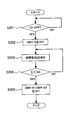
- step S101 the controller 40 determines whether or not the ignition switch of the vehicle has been switched from OFF to ON. Information relating to turning on and off the ignition switch is input to the controller 40. When the ignition switch is switched from OFF to ON, the process proceeds to step S102.
- step S102 the controller 40 switches the system main relays SMR-B1 and SMR-B2 from off to on.
- System main relays SMR-B1 and SMR-B2 can be switched on at different timings.
- step S103 the controller 40 switches the system main relay SMR-P from off to on.
- the assembled batteries 10 and 20 are connected to the inverter 41 when the system main relay SMR-P is turned on.
- the charging / discharging current of the assembled batteries 10 and 20 flows through the limiting resistor 35.
- the controller 40 switches the system main relay SMR-G from off to on in step S104, and switches the system main relay SMR-P from on to off in step S105. Thereby, the connection of the assembled batteries 10 and 20 and the inverter 41 is completed.
- both the assembled batteries 10 and 20 are connected to the inverter 41, but the present invention is not limited to this. Specifically, only one of the assembled batteries 10 and 20 can be connected to the inverter 41. In this case, the system main relay SMR-B1 (or system main relay SMR-B2) corresponding to the assembled battery 10 (or assembled battery 20) connected to the inverter 41 may be switched from off to on.
- step S106 the controller 40 controls charging / discharging of the assembled battery 10.20.
- charge / discharge control of the assembled batteries 10 and 20 known control can be appropriately employed.
- charging / discharging of the assembled batteries 10 and 20 can be controlled so that the voltages of the assembled batteries 10 and 20 change within a range of preset upper limit voltage and lower limit voltage.
- step S201 the controller 40 determines whether or not the ignition switch of the vehicle has been switched from on to off. When the ignition switch is switched from on to off, the process proceeds to step S202.
- step S202 the controller 40 switches the system main relay SMR-G from on to off. Thereby, the connection between the assembled batteries 10 and 20 and the inverter 41 is cut off.
- the system main relays SMR-B1 and SMR-B2 remain on, and the assembled batteries 10 and 20 remain connected in parallel. For this reason, if the electromotive voltage of the assembled battery 10 and the electromotive voltage (OCV; Open Circuit Voltage) of the assembled battery 20 are different, a current (circulating current) may flow between the assembled battery 10 and the assembled battery 20. Specifically, a current may flow from an assembled battery having a higher electromotive voltage to an assembled battery having a lower electromotive voltage.
- OCV Open Circuit Voltage
- step S203 the controller 40 detects the current (circulating current) Ij flowing between the assembled battery 10 and the assembled battery 20 based on the outputs of the current sensors 33 and 34. Possible causes for the difference in OCV between the assembled battery 10 and the assembled battery 20 are as follows.
- CCVs Current Circuit Voltage
- OCV Open Circuit Voltage
- CCV OCV + IR (1)
- I indicates the current flowing through each of the assembled batteries 10 and 20
- R indicates the internal resistance of each of the assembled batteries 10.20.
- OCV of the assembled batteries 10 and 20 may differ from each other by the independent equalization process.
- inrush current flows through the system main relays SMR-B1 and SMR-B2, and the system main relays SMR-B1 and SMR-B2 are prevented from deteriorating. .
- step S204 the controller 40 determines whether or not the circulating current Ij detected in step S203 is smaller than the threshold value Ith.
- the controller 40 determines whether or not the circulating current Ij detected in step S203 is smaller than the threshold value Ith.
- a circulating current Ij flows between the assembled batteries 10 and 20.
- the circulating current Ij decreases with time.
- the threshold value Ith is determined based on the OCV difference ⁇ V between the assembled batteries 10 and 20 and the rated voltage Vr of the system main relays SMR-B1 and SMR-B2. Specifically, the threshold value Ith is determined as described below.
- the OCV difference ⁇ V between the assembled batteries 10 and 20 is expressed by the following formula (2).
- ⁇ V Ij (R1 + R2) (2)
- R1 represents the internal resistance of the assembled battery 10
- R2 represents the internal resistance of the assembled battery 20.
- ⁇ V is lower than the rated voltage Vr of the system main relays SMR-B1 and SMR-B2, even if a circulating current flows between the assembled batteries 10 and 20, the system main relays SMR-B1 and SMR-B2 are deteriorated. Can be suppressed. Specifically, the condition of the following formula (3) may be satisfied. ⁇ V ⁇ Vr (3)
- the threshold value Ith can be specified if the values of the resistors R1 and R2 are determined in advance.
- a specific numerical value of the threshold value Ith can be set as appropriate within a range that satisfies Expression (4). According to Expression (4), the minimum value of the threshold value Ith is Vr / (R1 + R2).
- resistors R1 and R2 resistance values that the assembled batteries 10 and 20 can take are measured in advance in various usage environments, and the maximum value of these resistance values can be used.
- the resistances R1 and R2 can be specified based on the temperature of the battery packs 10 and 20 and the state of charge (SOC; State of charge).
- the resistance R1 can be specified by preparing in advance a map showing the correspondence relationship between the temperature of the battery pack 10, the SOC, and the resistance R1, and acquiring information on the temperature of the battery pack 10 and the SOC.
- the map described above can be stored in the memory 40a. If the resistor R1 can be expressed as a function of the temperature of the battery pack 10 and the SOC, the resistor R1 can be specified by calculation using this function.
- a temperature sensor may be provided in the assembled battery 10. Further, in order to obtain the SOC information of the assembled battery 10, the SOC of the assembled battery 10 is estimated using the detection result of the voltage sensor 31, or the assembled battery 10 is based on the integrated value of the charge / discharge current of the assembled battery 10. The SOC can be estimated. The integrated value of the charge / discharge current can be specified based on the output of the current sensor 33.
- the resistor R1 can be identified based on at least one of the temperature of the assembled battery 10 and the SOC.
- the resistance R2 can be specified in the same manner as the resistance R1.
- the resistors R1 and R2 may depend on the temperature and SOC of the assembled batteries 10 and 20, and therefore, accurate values can be used as the resistors R1 and R2 by considering the temperature and SOC.
- step S205 the controller 40 switches the system main relays SMR-B1, SMR-B2 from on to off.
- System main relays SMR-B1 and SMR-B2 can be switched from on to off at different timings.
- the two assembled batteries 10 and 20 are connected in parallel, but the present invention is not limited to this.
- the present invention can also be applied to a configuration in which three or more assembled batteries are connected in parallel.
- a system main relay corresponding to the system main relays SMR-B1 and SMR-B2 is connected to each assembled battery.
- the OCV difference ⁇ V is set to be equal to or lower than the rated voltage Vr, but the present invention is not limited to this. That is, it is only necessary to reduce the OCV difference ⁇ V by flowing a circulating current between the assembled batteries 10 and 20 before switching the system main relays SMR-B1 and SMR-B2 from on to off. By reducing the OCV difference ⁇ V in this way, it is possible to suppress the circulation current from flowing between the assembled batteries 10 and 20 when the system main relays SMR-B1 and SMR-B2 are turned on again. it can.
- the assembled batteries 10 and 20 having the same characteristics are used, but the present invention is not limited to this.
- a high-power assembled battery can be used as the assembled battery 10
- a high-capacity assembled battery can be used as the assembled battery 20.
- the high-power assembled battery 10 is an assembled battery that can be charged and discharged with a larger current than the high-capacity assembled battery 20.
- the high-capacity assembled battery 20 is an assembled battery having a larger storage capacity than the high-power assembled battery 10.
- lithium ion batteries are used as the single cells 11 and 21, for example, hard carbon (non-graphitizable carbon material) is used as the negative electrode active material of the single cell 11, and lithium manganese system is used as the positive electrode active material of the single cell 11.
- a composite oxide can be used.
- graphite graphite
- lithium / nickel composite oxide can be used as the positive electrode active material of the single battery 21.
- the single battery 11 of the high-power assembled battery 10 and the single battery 21 of the high-capacity assembled battery 20 have the relationship shown in Table 1 below when compared with each other.
- the output of the cells 11 and 21 is, for example, the power per unit mass of the cells 11 and 21 (unit [W / kg]) or the power per unit volume of the cells 11 and 21 (unit [ W / L]).
- the unit cell 11 is higher than the unit cell 21.
- the output [W] of the unit cell 11 is higher than the output [W] of the unit cell 21.
- the capacity of the unit cells 11 and 21 is, for example, the capacity per unit mass of the unit cells 11 and 21 (unit [Wh / kg]) or the capacity per unit volume of the unit cells 11 and 21 (unit [Wh / L]). ).
- the unit cell 21 is larger than the unit cell 11.
- the capacity [Wh] of the unit cell 21 is larger than the capacity [Wh] of the unit cell 11.
- the output of the electrodes of the unit cells 11 and 21 can be expressed, for example, as a current value per unit area of the electrode (unit [mA / cm ⁇ 2]).
- the cell 11 is higher than the cell 21 in terms of electrode output.
- the value of the current flowing through the electrode of the unit cell 11 is larger than the value of the current flowing through the electrode of the unit cell 21.
- the capacity of the electrodes of the unit cells 11 and 21 can be expressed as, for example, the capacity per unit mass of the electrode (unit [mAh / g]) or the capacity per unit volume of the electrode (unit [mAh / cc]). .
- the cell 21 is larger than the cell 11 in terms of electrode capacity.
- the capacity of the electrode of the unit cell 21 is larger than the capacity of the electrode of the unit cell 11.
- a battery system that is Embodiment 2 of the present invention will be described.
- the present embodiment is different from the first embodiment (FIG. 3) with respect to the processing when the ignition switch is switched from on to off.
- FIG. 3 A battery system that is Embodiment 2 of the present invention.
- FIG. 3 A battery system that is Embodiment 2 of the present invention.
- FIG. 3 A battery system that is Embodiment 2 of the present invention.
- FIG. 3 A battery system that is Embodiment 2 of the present invention.
- the present embodiment is different from the first embodiment (FIG. 3) with respect to the processing when the ignition switch is switched from on to off.
- FIG. 3 A battery system that is Embodiment 2 of the present invention.
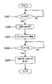
- FIG. 4 is a flowchart showing an operation when the connection between the assembled batteries 10 and 20 and the inverter 41 is cut off in the battery system of this embodiment. The process shown in FIG. 4 is executed by the controller 40.
- step S301 the controller 40 determines whether or not the ignition switch of the vehicle has been switched from on to off. When the ignition switch is switched from on to off, the process proceeds to step S302.
- step S302 the controller 40 switches the system main relay SMR-G from on to off. Thereby, the connection between the assembled batteries 10 and 20 and the inverter 41 is cut off.
- system main relays SMR-B1 and SMR-B2 remain on, assembled battery 10 and assembled battery 20 remain connected in parallel.
- step S303 the controller 40 starts counting time using a timer.
- the controller 40 includes a timer.
- step S304 the controller 40 determines whether or not the count time Tj of the timer is longer than the threshold value Tth. That is, the controller 40 stands by until the count time Tj becomes longer than the threshold value Tth.
- the controller 40 stands by until the count time Tj becomes longer than the threshold value Tth.
- Threshold value Tth can be set as described below, for example.
- a value ⁇ Vmax when the difference in OCV between the assembled batteries 10 and 20 is maximized is predicted.
- the voltage difference ⁇ Vmax occurs, for example, the deterioration state of the assembled battery 10 may be maximum, and the deterioration state of the assembled battery 20 may be minimum.
- the resistance of the assembled battery 10 is Rmax
- the resistance of the assembled battery 20 is Rmin. If the resistances Rini of the assembled batteries 10 and 20 in the initial state (immediately after manufacture) are equal to each other, the amount of change in the resistance Rmax with respect to the resistor Rini is the largest, and the amount of change in the resistance Rmin with respect to the resistor Rini is the smallest.
- the system main relays SMR-B1, SMR-B2 are caused by the circulating current (rush current) flowing between the assembled batteries 10.20. Can be prevented from deteriorating.
- the time until the voltage difference ⁇ Vmax reaches the rated voltage Vr is measured in advance, this time becomes the threshold value Tth. Since the current I flowing between the assembled batteries 10 and 20 decreases with time, the time until the voltage difference ⁇ Vmax reaches the rated voltage Vr can be specified in advance.
- the threshold value Tth specified in advance can be stored in the memory 40a.
- the voltage difference ⁇ V of the OCV between the assembled batteries 10 and 20 can be expressed by the following formula (6).
- ⁇ V ⁇ Vmax ⁇ e ⁇ ( ⁇ 2 kt / (Rmax + Rmin)) (6)
- ⁇ Vmax is a value when the difference in OCV between the assembled batteries 10 and 20 is maximized.
- ⁇ Vmax is a difference in OCV when the system main relay SMR-G is switched from on to off.
- k is a constant and t is time.
- Rmax is the resistance of the assembled battery 10 at which the deterioration state is maximized
- Rmin is the resistance of the assembled battery 20 at which the deterioration state is minimum.
- the time t until the voltage difference ⁇ V reaches the rated voltage Vr can be calculated. This time t becomes the threshold value Tth.
- the threshold value Tth can be specified by the two methods (examples) described above, but is not limited thereto. That is, the threshold value Tth may be set as the time until the OCV difference between the assembled batteries 10 and 20 becomes equal to or lower than the rated voltage Vr of the system main relays SMR-B1 and SMR-B2.
- step S305 the controller 40 switches the system main relays SMR-B1, SMR-B2 from on to off.
- System main relays SMR-B1 and SMR-B2 can be switched from on to off at different timings.
- the system main relay SMR-B1 and SMR-B2 can be switched from on to off.
- the system main relays SMR-B1 and SMR-B2 are switched from off to on in response to the next ignition switch on, the system main relays SMR-B1 and SMR-B2 deteriorate due to the circulating current. Can be suppressed.
Abstract
Priority Applications (5)
| Application Number | Priority Date | Filing Date | Title |
|---|---|---|---|
| US14/119,963 US20140103859A1 (en) | 2011-06-03 | 2011-06-03 | Electric storage system |
| JP2013517702A JP5682708B2 (ja) | 2011-06-03 | 2011-06-03 | 蓄電システム |
| EP11866542.1A EP2717415A4 (fr) | 2011-06-03 | 2011-06-03 | Système de stockage d'électricité |
| CN201180071207.2A CN103563206A (zh) | 2011-06-03 | 2011-06-03 | 蓄电系统 |
| PCT/JP2011/003151 WO2012164630A1 (fr) | 2011-06-03 | 2011-06-03 | Système de stockage d'électricité |
Applications Claiming Priority (1)
| Application Number | Priority Date | Filing Date | Title |
|---|---|---|---|
| PCT/JP2011/003151 WO2012164630A1 (fr) | 2011-06-03 | 2011-06-03 | Système de stockage d'électricité |
Publications (1)
| Publication Number | Publication Date |
|---|---|
| WO2012164630A1 true WO2012164630A1 (fr) | 2012-12-06 |
Family
ID=47258521
Family Applications (1)
| Application Number | Title | Priority Date | Filing Date |
|---|---|---|---|
| PCT/JP2011/003151 WO2012164630A1 (fr) | 2011-06-03 | 2011-06-03 | Système de stockage d'électricité |
Country Status (5)
| Country | Link |
|---|---|
| US (1) | US20140103859A1 (fr) |
| EP (1) | EP2717415A4 (fr) |
| JP (1) | JP5682708B2 (fr) |
| CN (1) | CN103563206A (fr) |
| WO (1) | WO2012164630A1 (fr) |
Cited By (14)
| Publication number | Priority date | Publication date | Assignee | Title |
|---|---|---|---|---|
| WO2014128941A1 (fr) * | 2013-02-25 | 2014-08-28 | 株式会社 日立製作所 | Système de stockage d'électricité connecté en parallèle |
| JP2014193094A (ja) * | 2013-03-28 | 2014-10-06 | Mazda Motor Corp | 車両用電源制御装置 |
| CN104908600A (zh) * | 2015-05-25 | 2015-09-16 | 金龙联合汽车工业(苏州)有限公司 | 一种电动车电池组的安全控制系统 |
| WO2015137222A1 (fr) * | 2014-03-12 | 2015-09-17 | 三菱電機株式会社 | Système d'alimentation électrique |
| JP2016208588A (ja) * | 2015-04-16 | 2016-12-08 | 日産自動車株式会社 | 電池のスイッチ制御システム及びスイッチ制御方法 |
| WO2018056263A1 (fr) * | 2016-09-21 | 2018-03-29 | オートモーティブエナジーサプライ株式会社 | Système d'alimentation électrique |
| JP2018160960A (ja) * | 2017-03-22 | 2018-10-11 | 株式会社豊田自動織機 | 蓄電装置 |
| JPWO2018056262A1 (ja) * | 2016-09-21 | 2019-04-25 | オートモーティブエナジーサプライ株式会社 | 電源システム |
| WO2019093048A1 (fr) * | 2017-11-13 | 2019-05-16 | 株式会社日立製作所 | Système combiné de stockage en énergie électrique |
| JPWO2021162077A1 (fr) * | 2020-02-12 | 2021-08-19 | ||
| WO2022054367A1 (fr) * | 2020-09-11 | 2022-03-17 | 本田技研工業株式会社 | Appareil d'alimentation électrique |
| WO2022070715A1 (fr) * | 2020-09-29 | 2022-04-07 | パナソニックIpマネジメント株式会社 | Dispositif de gestion et système d'alimentation en énergie |
| WO2022070716A1 (fr) * | 2020-09-29 | 2022-04-07 | パナソニックIpマネジメント株式会社 | Dispositif de gestion et système d'alimentation électrique |
| CN115916575B (zh) * | 2020-09-29 | 2024-05-14 | 松下知识产权经营株式会社 | 管理装置和电源系统 |
Families Citing this family (10)
| Publication number | Priority date | Publication date | Assignee | Title |
|---|---|---|---|---|
| JP6119143B2 (ja) * | 2011-11-01 | 2017-04-26 | 日産自動車株式会社 | 電源の制御装置 |
| DE102013221113A1 (de) * | 2013-10-17 | 2015-05-07 | Robert Bosch Gmbh | Elektrische Energiespeichervorrichtung |
| WO2016153215A1 (fr) | 2015-03-24 | 2016-09-29 | 이승규 | Interrupteur à fusibles, appareil de commande de batterie le comprenant, et procédé de commande de batterie |
| JP6409203B2 (ja) * | 2016-03-25 | 2018-10-24 | 本田技研工業株式会社 | 電源装置、輸送機器、電源制御方法、および制御装置 |
| US11233419B2 (en) * | 2017-08-10 | 2022-01-25 | Zoox, Inc. | Smart battery circuit |
| DE102017216486A1 (de) * | 2017-09-18 | 2019-03-21 | Robert Bosch Gmbh | Elektrisches Parallelschalten einer Mehrzahl von elektrischen Energiespeichern |
| JP7320734B2 (ja) * | 2018-01-30 | 2023-08-04 | パナソニックIpマネジメント株式会社 | 車両用電源システム、管理装置 |
| KR102530940B1 (ko) * | 2018-04-23 | 2023-05-11 | 현대자동차주식회사 | 차량용 에너지저장장치 시스템 |
| US10761530B2 (en) * | 2018-06-20 | 2020-09-01 | Faraday & Future Inc. | Redundant low-voltage battery system operation in electric vehicles |
| WO2021001046A1 (fr) * | 2019-07-04 | 2021-01-07 | Volvo Truck Corporation | Procédé pour commander la connexion électrique de blocs-batteries |
Citations (3)
| Publication number | Priority date | Publication date | Assignee | Title |
|---|---|---|---|---|
| JP2009033936A (ja) * | 2007-07-30 | 2009-02-12 | Toshiba Corp | 並列接続蓄電システム |
| JP2009081078A (ja) * | 2007-09-27 | 2009-04-16 | Hitachi Ltd | 蓄電池保管装置および蓄電池保管方法 |
| JP2011072153A (ja) * | 2009-09-28 | 2011-04-07 | Sanyo Electric Co Ltd | 車両用電源装置及びこれを備える車両並びに車両用電源装置の容量均等化方法 |
Family Cites Families (8)
| Publication number | Priority date | Publication date | Assignee | Title |
|---|---|---|---|---|
| JP2003143713A (ja) * | 2001-11-05 | 2003-05-16 | Komatsu Ltd | ハイブリッド電源システム |
| CN100581024C (zh) * | 2008-09-19 | 2010-01-13 | 哈尔滨工业大学 | 蓄电池组或超级电容器组充放电快速均衡装置 |
| EP2272722B1 (fr) * | 2009-07-01 | 2015-04-08 | Denso Corporation | Appareil de source d'alimentation pour véhicule |
| JP4893804B2 (ja) * | 2009-11-05 | 2012-03-07 | トヨタ自動車株式会社 | 車両用電源装置 |
| JP5664446B2 (ja) * | 2011-04-28 | 2015-02-04 | トヨタ自動車株式会社 | 電池システム |
| JP5440708B2 (ja) * | 2011-06-07 | 2014-03-12 | トヨタ自動車株式会社 | 電池システムおよび、電池システムの制御方法 |
| WO2013061358A1 (fr) * | 2011-10-24 | 2013-05-02 | トヨタ自動車株式会社 | Système d'accumulation d'électricité |
| JP5605401B2 (ja) * | 2012-07-20 | 2014-10-15 | トヨタ自動車株式会社 | 蓄電システムおよび制御方法 |
-
2011
- 2011-06-03 US US14/119,963 patent/US20140103859A1/en not_active Abandoned
- 2011-06-03 CN CN201180071207.2A patent/CN103563206A/zh active Pending
- 2011-06-03 EP EP11866542.1A patent/EP2717415A4/fr not_active Withdrawn
- 2011-06-03 JP JP2013517702A patent/JP5682708B2/ja active Active
- 2011-06-03 WO PCT/JP2011/003151 patent/WO2012164630A1/fr active Application Filing
Patent Citations (3)
| Publication number | Priority date | Publication date | Assignee | Title |
|---|---|---|---|---|
| JP2009033936A (ja) * | 2007-07-30 | 2009-02-12 | Toshiba Corp | 並列接続蓄電システム |
| JP2009081078A (ja) * | 2007-09-27 | 2009-04-16 | Hitachi Ltd | 蓄電池保管装置および蓄電池保管方法 |
| JP2011072153A (ja) * | 2009-09-28 | 2011-04-07 | Sanyo Electric Co Ltd | 車両用電源装置及びこれを備える車両並びに車両用電源装置の容量均等化方法 |
Non-Patent Citations (1)
| Title |
|---|
| See also references of EP2717415A4 * |
Cited By (23)
| Publication number | Priority date | Publication date | Assignee | Title |
|---|---|---|---|---|
| WO2014128941A1 (fr) * | 2013-02-25 | 2014-08-28 | 株式会社 日立製作所 | Système de stockage d'électricité connecté en parallèle |
| JP5965538B2 (ja) * | 2013-02-25 | 2016-08-10 | 株式会社日立製作所 | 並列接続蓄電システム |
| US9627718B2 (en) | 2013-02-25 | 2017-04-18 | Hitachi, Ltd. | Parallel-connected electricity storage system |
| JP2014193094A (ja) * | 2013-03-28 | 2014-10-06 | Mazda Motor Corp | 車両用電源制御装置 |
| WO2015137222A1 (fr) * | 2014-03-12 | 2015-09-17 | 三菱電機株式会社 | Système d'alimentation électrique |
| JPWO2015137222A1 (ja) * | 2014-03-12 | 2017-04-06 | 三菱電機株式会社 | 電源システム |
| US9711979B2 (en) | 2014-03-12 | 2017-07-18 | Mitsubishi Electric Corporation | Power supply system |
| JP2016208588A (ja) * | 2015-04-16 | 2016-12-08 | 日産自動車株式会社 | 電池のスイッチ制御システム及びスイッチ制御方法 |
| CN104908600A (zh) * | 2015-05-25 | 2015-09-16 | 金龙联合汽车工业(苏州)有限公司 | 一种电动车电池组的安全控制系统 |
| CN107863789A (zh) * | 2016-09-21 | 2018-03-30 | 汽车能源供应公司 | 电源系统 |
| WO2018056263A1 (fr) * | 2016-09-21 | 2018-03-29 | オートモーティブエナジーサプライ株式会社 | Système d'alimentation électrique |
| JPWO2018056262A1 (ja) * | 2016-09-21 | 2019-04-25 | オートモーティブエナジーサプライ株式会社 | 電源システム |
| JPWO2018056263A1 (ja) * | 2016-09-21 | 2019-06-24 | オートモーティブエナジーサプライ株式会社 | 電源システム |
| CN107863789B (zh) * | 2016-09-21 | 2021-03-02 | 远景Aesc日本有限公司 | 电源系统 |
| JP2018160960A (ja) * | 2017-03-22 | 2018-10-11 | 株式会社豊田自動織機 | 蓄電装置 |
| WO2019093048A1 (fr) * | 2017-11-13 | 2019-05-16 | 株式会社日立製作所 | Système combiné de stockage en énergie électrique |
| JPWO2021162077A1 (fr) * | 2020-02-12 | 2021-08-19 | ||
| JP7176156B2 (ja) | 2020-02-12 | 2022-11-21 | 古河電気工業株式会社 | 蓄電池システムの劣化判定装置、蓄電池システムの劣化判定方法、蓄電池システム及び蓄電池監視装置 |
| WO2022054367A1 (fr) * | 2020-09-11 | 2022-03-17 | 本田技研工業株式会社 | Appareil d'alimentation électrique |
| WO2022070715A1 (fr) * | 2020-09-29 | 2022-04-07 | パナソニックIpマネジメント株式会社 | Dispositif de gestion et système d'alimentation en énergie |
| WO2022070716A1 (fr) * | 2020-09-29 | 2022-04-07 | パナソニックIpマネジメント株式会社 | Dispositif de gestion et système d'alimentation électrique |
| CN115916575A (zh) * | 2020-09-29 | 2023-04-04 | 松下知识产权经营株式会社 | 管理装置和电源系统 |
| CN115916575B (zh) * | 2020-09-29 | 2024-05-14 | 松下知识产权经营株式会社 | 管理装置和电源系统 |
Also Published As
| Publication number | Publication date |
|---|---|
| JPWO2012164630A1 (ja) | 2014-07-31 |
| US20140103859A1 (en) | 2014-04-17 |
| CN103563206A (zh) | 2014-02-05 |
| EP2717415A1 (fr) | 2014-04-09 |
| JP5682708B2 (ja) | 2015-03-11 |
| EP2717415A4 (fr) | 2015-07-22 |
Similar Documents
| Publication | Publication Date | Title |
|---|---|---|
| JP5682708B2 (ja) | 蓄電システム | |
| JP5440708B2 (ja) | 電池システムおよび、電池システムの制御方法 | |
| US9933491B2 (en) | Electric storage system | |
| JP5862631B2 (ja) | 蓄電システム | |
| JP6445190B2 (ja) | 電池制御装置 | |
| JP5621818B2 (ja) | 蓄電システムおよび均等化方法 | |
| US20110089905A1 (en) | Power supply device | |
| JP5738784B2 (ja) | 蓄電システム | |
| JP7043944B2 (ja) | 蓄電装置 | |
| WO2013061358A1 (fr) | Système d'accumulation d'électricité | |
| JP5796457B2 (ja) | バッテリシステムおよびバッテリシステムの制御方法 | |
| JP2013121242A (ja) | Soc推定装置及び電池パック | |
| JP5626190B2 (ja) | 蓄電システム | |
| JP2012234697A (ja) | 電池システム | |
| JP6017790B2 (ja) | 蓄電システム | |
| JP5891604B2 (ja) | 電池システム | |
| JP5609807B2 (ja) | バッテリ装置のヒステリシス低減システム | |
| JP5772615B2 (ja) | 蓄電システム | |
| WO2013105139A1 (fr) | Procédé et dispositif de commande de batterie rechargeable | |
| JP2012165580A (ja) | 蓄電装置の制御装置 | |
| JP5999048B2 (ja) | 蓄電システム | |
| JP2013243869A (ja) | 二次電池の制御装置 | |
| JP6919302B2 (ja) | 車両用蓄電装置 | |
| WO2012172592A1 (fr) | Système de batterie et procédé de commande d'un dispositif à batterie | |
| JP5257173B2 (ja) | 車載電源装置 |
Legal Events
| Date | Code | Title | Description |
|---|---|---|---|
| 121 | Ep: the epo has been informed by wipo that ep was designated in this application |
Ref document number: 11866542 Country of ref document: EP Kind code of ref document: A1 |
|
| ENP | Entry into the national phase |
Ref document number: 2013517702 Country of ref document: JP Kind code of ref document: A |
|
| WWE | Wipo information: entry into national phase |
Ref document number: 14119963 Country of ref document: US |
|
| NENP | Non-entry into the national phase |
Ref country code: DE |
|
| REEP | Request for entry into the european phase |
Ref document number: 2011866542 Country of ref document: EP |
|
| WWE | Wipo information: entry into national phase |
Ref document number: 2011866542 Country of ref document: EP |