WO2013105139A1 - Procédé et dispositif de commande de batterie rechargeable - Google Patents
Procédé et dispositif de commande de batterie rechargeable Download PDFInfo
- Publication number
- WO2013105139A1 WO2013105139A1 PCT/JP2012/000189 JP2012000189W WO2013105139A1 WO 2013105139 A1 WO2013105139 A1 WO 2013105139A1 JP 2012000189 W JP2012000189 W JP 2012000189W WO 2013105139 A1 WO2013105139 A1 WO 2013105139A1
- Authority
- WO
- WIPO (PCT)
- Prior art keywords
- secondary battery
- voltage
- unit cell
- upper limit
- battery
- Prior art date
Links
Images


Classifications
-
- H—ELECTRICITY
- H01—ELECTRIC ELEMENTS
- H01M—PROCESSES OR MEANS, e.g. BATTERIES, FOR THE DIRECT CONVERSION OF CHEMICAL ENERGY INTO ELECTRICAL ENERGY
- H01M10/00—Secondary cells; Manufacture thereof
- H01M10/42—Methods or arrangements for servicing or maintenance of secondary cells or secondary half-cells
- H01M10/48—Accumulators combined with arrangements for measuring, testing or indicating the condition of cells, e.g. the level or density of the electrolyte
-
- H—ELECTRICITY
- H01—ELECTRIC ELEMENTS
- H01M—PROCESSES OR MEANS, e.g. BATTERIES, FOR THE DIRECT CONVERSION OF CHEMICAL ENERGY INTO ELECTRICAL ENERGY
- H01M10/00—Secondary cells; Manufacture thereof
- H01M10/42—Methods or arrangements for servicing or maintenance of secondary cells or secondary half-cells
- H01M10/44—Methods for charging or discharging
-
- H—ELECTRICITY
- H02—GENERATION; CONVERSION OR DISTRIBUTION OF ELECTRIC POWER
- H02J—CIRCUIT ARRANGEMENTS OR SYSTEMS FOR SUPPLYING OR DISTRIBUTING ELECTRIC POWER; SYSTEMS FOR STORING ELECTRIC ENERGY
- H02J7/00—Circuit arrangements for charging or depolarising batteries or for supplying loads from batteries
- H02J7/007—Regulation of charging or discharging current or voltage
- H02J7/00712—Regulation of charging or discharging current or voltage the cycle being controlled or terminated in response to electric parameters
-
- G—PHYSICS
- G01—MEASURING; TESTING
- G01R—MEASURING ELECTRIC VARIABLES; MEASURING MAGNETIC VARIABLES
- G01R31/00—Arrangements for testing electric properties; Arrangements for locating electric faults; Arrangements for electrical testing characterised by what is being tested not provided for elsewhere
- G01R31/36—Arrangements for testing, measuring or monitoring the electrical condition of accumulators or electric batteries, e.g. capacity or state of charge [SoC]
- G01R31/392—Determining battery ageing or deterioration, e.g. state of health
-
- H—ELECTRICITY
- H01—ELECTRIC ELEMENTS
- H01M—PROCESSES OR MEANS, e.g. BATTERIES, FOR THE DIRECT CONVERSION OF CHEMICAL ENERGY INTO ELECTRICAL ENERGY
- H01M2220/00—Batteries for particular applications
- H01M2220/20—Batteries in motive systems, e.g. vehicle, ship, plane
-
- H—ELECTRICITY
- H02—GENERATION; CONVERSION OR DISTRIBUTION OF ELECTRIC POWER
- H02J—CIRCUIT ARRANGEMENTS OR SYSTEMS FOR SUPPLYING OR DISTRIBUTING ELECTRIC POWER; SYSTEMS FOR STORING ELECTRIC ENERGY
- H02J7/00—Circuit arrangements for charging or depolarising batteries or for supplying loads from batteries
- H02J7/0069—Charging or discharging for charge maintenance, battery initiation or rejuvenation
-
- Y—GENERAL TAGGING OF NEW TECHNOLOGICAL DEVELOPMENTS; GENERAL TAGGING OF CROSS-SECTIONAL TECHNOLOGIES SPANNING OVER SEVERAL SECTIONS OF THE IPC; TECHNICAL SUBJECTS COVERED BY FORMER USPC CROSS-REFERENCE ART COLLECTIONS [XRACs] AND DIGESTS
- Y02—TECHNOLOGIES OR APPLICATIONS FOR MITIGATION OR ADAPTATION AGAINST CLIMATE CHANGE
- Y02E—REDUCTION OF GREENHOUSE GAS [GHG] EMISSIONS, RELATED TO ENERGY GENERATION, TRANSMISSION OR DISTRIBUTION
- Y02E60/00—Enabling technologies; Technologies with a potential or indirect contribution to GHG emissions mitigation
- Y02E60/10—Energy storage using batteries
Definitions
- the present invention relates to a control device and a control method for controlling charge / discharge of a secondary battery.
- the charging of the secondary battery is controlled so that the voltage of the secondary battery does not become higher than a predetermined upper limit voltage.
- the discharge of the secondary battery is controlled so that the voltage of the secondary battery does not become lower than a predetermined lower limit voltage.
- the secondary battery may be excessively restricted from being charged or discharged, or overcharge or overdischarge may be difficult to suppress.
- 1st invention of this application is a control apparatus which controls charging / discharging of a secondary battery, Comprising: It has a controller which sets the threshold voltage which can perform charging / discharging of a secondary battery.
- the controller specifies the current deterioration state of the secondary battery, and sets the threshold voltage corresponding to the current deterioration state using information in which the threshold voltage changes with the progress of deterioration of the secondary battery.
- charging / discharging of the secondary battery can be controlled using the threshold voltage corresponding to the current deterioration state. Thereby, depending on the threshold voltage, it can be prevented that charging / discharging of the secondary battery is excessively limited or charging / discharging of the secondary battery is difficult to limit. And the input-output performance of a secondary battery can fully be exhibited.
- Threshold voltage includes an upper limit voltage that can charge the secondary battery and a lower limit voltage that can discharge the secondary battery.
- the upper limit voltage can be continuously reduced according to the progress of deterioration of the secondary battery. By reducing the upper limit voltage according to the progress (degradation state) of the secondary battery, it is possible to prevent the secondary battery from being excessively restricted from charging or to suppress overcharge of the secondary battery. Can be.
- the lower limit voltage can be continuously increased as the secondary battery deteriorates.
- By increasing the lower limit voltage according to the degree of progress (degradation state) of the secondary battery it is possible to prevent the secondary battery from being restricted excessively or to suppress the secondary battery from over-discharge. Can be.
- the upper limit value of power that allows charging of the secondary battery can be reduced.
- Reducing the upper limit value of the charging power includes setting the upper limit value to 0 [kW], in other words, not charging the secondary battery.
- the upper limit value of power that allows the secondary battery to discharge can be reduced.
- the voltage of the secondary battery can be suppressed from becoming lower than the lower limit voltage.
- Reducing the upper limit value of the discharge power includes setting the upper limit value to 0 [kW], in other words, not discharging the secondary battery.
- the deterioration state of the secondary battery can be specified using at least one of the capacity, resistance, and usage time of the secondary battery. Since the capacity of the secondary battery decreases as the deterioration of the secondary battery proceeds, the deterioration state of the secondary battery can be specified using the capacity of the secondary battery. Since the resistance of the secondary battery increases as the deterioration of the secondary battery progresses, the deterioration state of the secondary battery can be specified using the resistance of the secondary battery. If the secondary battery continues to be used, aged deterioration occurs. Therefore, the deterioration state of the secondary battery can be specified using the usage time of the secondary battery.
- a second invention of the present application is a control method for controlling charging / discharging of a secondary battery, wherein a threshold voltage that can identify the current deterioration state of the secondary battery and charge / discharge the secondary battery is secondary.
- a threshold voltage corresponding to the current deterioration state is set using information that changes with the progress of battery deterioration. Also in the second invention of the present application, the same effect as that of the first invention of the present application can be obtained.
- FIG. 1 is a diagram illustrating a configuration of a battery system.
- the battery system of the present embodiment can be mounted on a vehicle.
- Vehicles include hybrid cars and electric cars.
- the hybrid vehicle includes an engine or a fuel cell as a power source for running the vehicle in addition to the assembled battery described later.
- the electric vehicle includes only an assembled battery described later as a power source for running the vehicle.
- the assembled battery 10 has a plurality of unit cells 11 connected in series.
- a secondary battery such as a nickel metal hydride battery or a lithium ion battery can be used.
- the number of unit cells 11 constituting the assembled battery 10 can be appropriately set based on the required output of the assembled battery 10 and the like. In the present embodiment, all the unit cells 11 constituting the assembled battery 10 are connected in series, but the present invention is not limited to this.
- a plurality of unit cells 11 connected in parallel may be included in the assembled battery 10.
- the unit cell 11 has a power generation element that charges and discharges and a battery case that houses the power generation element.
- the power generation element can be composed of, for example, a positive electrode plate, a negative electrode plate, and a separator disposed between the positive electrode plate and the negative electrode plate.
- the positive electrode plate includes a current collector plate and a positive electrode active material layer formed on the surface of the current collector plate.
- the negative electrode plate has a current collector plate and a negative electrode active material layer formed on the surface of the current collector plate.
- the positive electrode active material layer includes a positive electrode active material and a conductive agent
- the negative electrode active material layer includes a negative electrode active material and a conductive agent.
- the current collector plate of the positive electrode plate can be formed of aluminum, and the current collector plate of the negative electrode plate can be formed of copper.
- the positive electrode active material for example, LiCo 1/3 Ni 1/3 Mn 1/3 O 2 can be used, and as the negative electrode active material, for example, carbon can be used.
- An electrolyte solution is infiltrated into the separator, the positive electrode active material layer, and the negative electrode active material layer.
- a solid electrolyte layer may be disposed between the positive electrode plate and the negative electrode plate.
- the voltage sensor 21 detects the voltage of each cell 11 and outputs the detection result to the controller 30.
- the voltage sensor 21 is used to detect the voltage of each cell 11, but this is not a limitation.
- the plurality of single cells 11 constituting the assembled battery 10 can be divided into a plurality of battery blocks, and the voltage of each battery block can be detected.
- the plurality of battery blocks are connected in series, and each battery block includes a plurality of single cells 11 connected in series.
- the number of single cells 11 constituting each battery block can be set as appropriate.
- the current sensor 22 detects the current value flowing through the assembled battery 10 (unit cell 11) and outputs the detection result to the controller 30.
- the controller 30 has a built-in memory 31.
- the memory 31 stores a program for operating the controller 30 and specific information.
- the memory 31 can also be provided outside the controller 30.
- the system main relay SMR-B is provided on the positive electrode line PL of the assembled battery 10. System main relay SMR-B is switched between on and off by receiving a control signal from controller 30.
- a system main relay SMR-G is provided on the negative electrode line NL of the assembled battery 10. System main relay SMR-G is switched between on and off by receiving a control signal from controller 30.
- System main relay SMR-P and current limiting resistor R are connected in parallel to system main relay SMR-G.
- System main relay SMR-P and current limiting resistor R are connected in series.
- System main relay SMR-P is switched between on and off in response to a control signal from controller 30.
- the current limiting resistor R is used for suppressing an inrush current from flowing when the assembled battery 10 is connected to a load (specifically, a booster circuit 23 described later).
- the controller 30 controls the turning on and off of the system main relays SMR-B, SMR-G, and SMR-P, thereby connecting the assembled battery 10 to a load and cutting off the connection between the assembled battery 10 and the load. be able to.
- the booster circuit 23 boosts the output voltage of the assembled battery 10 and outputs the boosted power to the inverter 24. Further, the booster circuit 23 can step down the output voltage of the inverter 24 and output the reduced power to the assembled battery 10.
- the booster circuit 23 operates in response to a control signal from the controller 30. In the battery system of this embodiment, the booster circuit 23 is used, but the booster circuit 23 may be omitted.
- the inverter 24 converts the DC power output from the booster circuit 23 into AC power and outputs the AC power to the motor / generator 25.
- the inverter 24 converts AC power generated by the motor / generator 25 into DC power and outputs the DC power to the booster circuit 23.
- a three-phase AC motor can be used as the motor / generator 25.
- the motor / generator 25 receives AC power from the inverter 24 and generates kinetic energy for running the vehicle. When the vehicle is driven using the electric power of the assembled battery 10, the kinetic energy generated by the motor / generator 25 is transmitted to the wheels.
- the motor / generator 25 converts kinetic energy generated during braking of the vehicle into electric energy (AC power).
- the electric energy generated by the motor / generator 25 is supplied to the assembled battery 10 via the inverter 24 and the booster circuit 23. Thereby, regenerative electric power can be stored in the assembled battery 10.
- charging of the cell 11 is controlled so that the voltage of the cell 11 does not become higher than the upper limit voltage in order to suppress overcharging of the cell 11.
- the discharge of the single battery 11 is controlled so that the voltage of the single battery 11 does not become lower than the lower limit voltage.
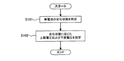
- FIG. 2 is a flowchart showing processing for setting an upper limit voltage and a lower limit voltage. The process shown in FIG. 2 is executed by the controller 30.
- step S101 the controller 30 specifies the deterioration state of the unit cell 11.
- the controller 30 can specify the deterioration state of the unit cell 11 based on the capacity, resistance, usage period, and the like of the unit cell 11.
- capacitance, resistance, and a use period become a parameter
- the deterioration state of the cell 11 can be specified. Further, since the unit cell 11 may be deteriorated due to wear or the like due to a change with time, the deterioration state of the unit cell 11 can be specified by measuring the usage period of the unit cell 11. The usage period of the unit cell 11 can be measured using a timer, for example.
- the current value flowing through the unit cell 11 is integrated while the voltage of the unit cell 11 is changed from the first voltage to the second voltage.
- the voltage of the cell 11 can be reduced from the first voltage to the second voltage (second voltage ⁇ first voltage).
- the voltage of the cell 11 can be increased from the first voltage to the second voltage (second voltage> first voltage).
- an external power source When charging the cell 11, an external power source can be used.
- the external power source is a power source provided separately from the battery system shown in FIG.
- As the external power source for example, a commercial power source can be used.
- the power of the external power source can be supplied to the assembled battery 10 to charge the assembled battery 10 (unit cell 11).
- the unit cell 11 is compared by comparing the current integrated value of the unit cell 11 in the initial state with the measured current integrated value. It is possible to specify the deterioration state of the.
- the initial state is a state in which the unit cell 11 has not deteriorated, and refers to a state immediately after the unit cell 11 is manufactured. When the measured current integrated value is smaller than the current integrated value of the cell 11 in the initial state, it can be seen that the cell 11 is in a deteriorated state.
- the internal resistance of the cell 11 can be calculated from the voltage value and current value of the cell 11.
- the controller 30 can acquire the voltage value of the single battery 11 based on the output of the voltage sensor 21. Further, the controller 30 can acquire the current value of the unit cell 11 based on the output of the current sensor 22. As the deterioration of the unit cell 11 progresses, the internal resistance of the unit cell 11 increases, so that the deterioration state of the unit cell 11 can be specified by monitoring the internal resistance of the unit cell 11.
- the method for specifying the deterioration state of the unit cell 11 is not limited to the method described above. Any method can be used as long as it can determine the deterioration state of the unit cell 11, in other words, the deterioration of the input / output characteristics of the unit cell 11.
- step S102 the controller 30 sets an upper limit voltage and a lower limit voltage corresponding to the deterioration state specified in step S101.
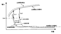
- the upper limit voltage Vu_lim and the lower limit voltage Vl_lim change according to the deterioration state of the unit cell 11. Specifically, the upper limit voltage Vu_lim continuously decreases as the deterioration of the unit cell 11 progresses. Further, the lower limit voltage Vl_lim continuously increases as the deterioration of the unit cell 11 progresses.
- the information shown in FIG. 3 can be acquired in advance by an experiment or the like and stored in the memory 31.
- the controller 30 can specify the upper limit voltage Vu_lim and the lower limit voltage Vl_lim corresponding to the deterioration state specified in step S101 using the information shown in FIG.
- a correspondence relationship between this index and the upper limit voltage Vu_lim and the lower limit voltage Vl_lim may be obtained in advance.
- the correspondence between these indicators and Vu_lim and the lower limit voltage Vl_lim may be obtained in advance.
- the lower limit voltage Vl_lim changes between the voltage V1 and the voltage V2.
- the voltage V1 is an upper limit voltage used in charge / discharge control of the cell 11 in the initial state.
- the voltage V2 is an upper limit voltage used in charge / discharge control of the unit cell 1 when it is determined that the deterioration state of the unit cell 11 is a lifetime.
- the voltage V2 is higher than the voltage V1.
- FIG. 4 shows the positive electrode potential and the negative electrode potential when the unit cell 11 is discharged.
- the positive electrode potential is the electrical potential energy of the positive electrode active material with respect to the reference potential located between the positive electrode and the negative electrode.
- the negative electrode potential is the electrical potential energy of the negative electrode active material with respect to the reference potential.
- the positive electrode open potential shown in FIG. 4 is a positive electrode potential when the cell 11 is in an initial state and in an unloaded state. As shown in FIG. 4, the positive electrode potential during discharge is lower than the positive electrode open potential by a potential corresponding to the resistance component (internal resistance) of the unit cell 11.
- the negative electrode open-circuit potential shown in FIG. 4 is a negative electrode potential when the unit cell 11 is in an initial state and in a no-load state. As shown in FIG. 4, the negative electrode potential at the time of discharging is higher than the negative electrode open potential by a potential corresponding to the resistance component (internal resistance) of the unit cell 11.
- the negative electrode potential shifts to the right side of FIG. 4 with respect to the positive electrode potential.
- the shift amount of the negative electrode potential varies depending on the deterioration state of the unit cell 11. That is, as the deterioration of the unit cell 11 proceeds, the amount of shift of the negative electrode potential increases.
- the positive electrode potential is fixed and only the negative electrode potential is shifted in order to represent the deterioration state of the unit cell 11, but this is not restrictive. That is, when the unit cell 11 is in a deteriorated state, the correspondence relationship between the positive electrode potential and the negative electrode potential is relatively shifted in the left-right direction in FIG.
- the current collector plate (eg, copper) of the negative electrode plate may be eluted.
- the negative electrode potential during discharge increases, the positive electrode potential during discharge decreases, and when the positive electrode potential during discharge decreases excessively, the structure of the positive electrode may change. If the reaction that occurs first among these secondary reactions at the positive and negative electrodes is known, the potential at which this reaction occurs can be set as the threshold potential Vth1.
- the negative electrode potential during discharge needs to be changed within a range lower than the threshold potential Vth1.
- the voltage of the unit cell 11 corresponds to the difference between the positive electrode potential and the negative electrode potential during discharge.
- the negative electrode potential during discharge needs to be changed within a range lower than the threshold potential Vth1.
- the threshold potential Vth1 when the cell 11 is in a deteriorated state, it is necessary to suppress the voltage of the cell 11 from being lower than the voltage Vc2.
- the battery voltage Vc2 becomes higher than the battery voltage Vc1.
- the battery voltage Vc1 shown in FIG. 4 corresponds to the battery voltage V1 shown in FIG.
- FIG. 5 shows the positive electrode potential and the negative electrode potential when the cell 11 is charged.
- the positive electrode potential during charging is higher than the positive electrode open potential by a potential corresponding to the resistance component (internal resistance) of the unit cell 11.
- the negative electrode potential during charging is lower than the negative electrode open potential by a potential corresponding to the resistance component (internal resistance) of the unit cell 11.
- the positive electrode open potential and the negative electrode open potential shown in FIG. 5 are the same as the positive electrode open potential and the negative electrode open potential shown in FIG.
- the positive electrode potential shifts to the left side in FIG. 5 with respect to the negative electrode potential.
- the shift amount of the positive electrode potential varies depending on the deterioration state of the unit cell 11. That is, the amount of shift of the positive electrode potential increases as the deterioration of the unit cell 11 progresses.
- the negative electrode potential is fixed and only the positive electrode potential is shifted in order to represent the deterioration state of the unit cell 11, but this is not restrictive. That is, when the unit cell 11 is in a deteriorated state, the correspondence relationship between the positive electrode potential and the negative electrode potential is relatively shifted in the left-right direction in FIG.
- the positive electrode potential during charging needs to be changed within a range lower than the threshold potential Vth2. In other words, when the unit cell 11 is in the initial state, it is necessary to suppress the voltage of the unit cell 11 from becoming higher than the voltage Vc3.
- the positive electrode potential during charging needs to be changed within a range lower than the threshold potential Vth2.
- the threshold potential Vth2 when the cell 11 is in a deteriorated state, it is necessary to suppress the voltage of the cell 11 from becoming higher than the voltage Vc4.
- the battery voltage Vc4 becomes lower than the battery voltage Vc3.
- the battery voltage Vc3 shown in FIG. 5 corresponds to the battery voltage V4 shown in FIG.
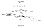
- step S201 the controller 30 acquires the detection voltage of the voltage sensor 21.
- step S202 the controller 30 determines whether or not the detected voltage is higher than the upper limit voltage Vu_lim.
- the upper limit voltage Vu_lim is a value set by the process shown in FIG. When the detected voltage is higher than the upper limit voltage Vu_lim, the process proceeds to step S203. When the detected voltage is lower than the upper limit voltage Vu_lim, the process proceeds to step S204.
- step S203 the controller 30 restricts the input of the unit cell 11. Specifically, the controller 30 reduces the upper limit power that can allow the input of the single battery 11.
- the charging of the cell 11 is controlled so that the input power of the cell 11 does not become higher than the upper limit power. Therefore, the charging of the unit cell 11 is suppressed by reducing the upper limit power.
- Decreasing the upper limit power includes setting the upper limit power to 0 [kW]. By setting the upper limit power to 0 [kW], the unit cell 11 is not charged.
- step S204 the controller 30 determines whether or not the detected voltage is lower than the lower limit voltage Vl_lim. When the detected voltage is lower than the lower limit voltage Vl_lim, the process proceeds to step S205.
- step S205 the controller 30 limits the output of the unit cell 11. Specifically, the controller 30 reduces the upper limit power that can allow the output of the single battery 11.
- the discharge of the cell 11 is controlled so that the output power of the cell 11 does not become higher than the upper limit power. Therefore, the discharge of the cell 11 is suppressed by reducing the upper limit power.
- Decreasing the upper limit power includes setting the upper limit power to 0 [kW]. By setting the upper limit power to 0 [kW], the unit cell 11 is not discharged.
- step S204 when the detected voltage is higher than the lower limit voltage Vl_lim, the processing shown in FIG. That is, the controller 30 does not decrease the upper limit power corresponding to the input / output of the unit cell 11.
- the upper limit voltage and the lower limit voltage of the unit cell 11 are set, but the present invention is not limited to this. Specifically, when monitoring the voltage of the battery block, an upper limit voltage and a lower limit voltage can be set for the voltage of the battery block.
- each of the upper limit voltage and the lower limit voltage of the battery block constitutes a battery block with respect to each of the upper limit voltage and the lower limit voltage of the single cell 11. What is necessary is just to multiply the number of the single cells 11.
- the unit cell 11 since the lower limit voltage Vl_lim corresponding to the deterioration state of the unit cell 11 is set, the unit cell 11 is made efficient while suppressing the negative electrode potential during discharge from becoming higher than the threshold potential Vth1. It can discharge well. That is, the output performance of the unit cell 11 can be sufficiently exhibited.
- the charging / discharging of the cell 11 is controlled, if the upper limit voltage Vu_lim is fixed to the voltage V4 (see FIG. 3), the positive electrode potential at the time of charging becomes the threshold potential Vth2 (see FIG. 5) when the cell 11 deteriorates. May be higher than If the upper limit voltage Vu_lim is fixed at the voltage V3 (see FIG. 3), the charging of the unit cell 11 is excessively limited when the unit cell 11 is not deteriorated.
- the unit cell 11 since the upper limit voltage Vu_lim corresponding to the deterioration state of the unit cell 11 is set, the unit cell 11 is made efficient while suppressing the positive electrode potential during charging from being higher than the threshold potential Vth2. It can be charged well. That is, the input performance of the unit cell 11 can be sufficiently exhibited.
- the present invention is not limited to this. That is, in the apparatus provided with the unit cell 11, the upper limit voltage and the lower limit voltage according to the deterioration state of the unit cell 11 can be set as described in the present embodiment.
Landscapes
- Engineering & Computer Science (AREA)
- Manufacturing & Machinery (AREA)
- Chemical & Material Sciences (AREA)
- Chemical Kinetics & Catalysis (AREA)
- Electrochemistry (AREA)
- General Chemical & Material Sciences (AREA)
- Power Engineering (AREA)
- Secondary Cells (AREA)
Abstract
Cette invention concerne un procédé et un dispositif de commande de batterie rechargeable assurant la mise en valeur de la performance d'entrée/sortie d'une batterie rechargeable tout en supprimant les problèmes de surcharge et de décharge excessive de la batterie. Ledit dispositif de commande qui commande la charge/décharge d'une batterie rechargeable, comprend un contrôler qui définit une tension seuil à laquelle la charge/décharge de la batterie rechargeable peut être exécutée. Le contrôleur identifie l'état d'usure actuel de la batterie rechargeable, et la tension seuil est définie en fonction de l'état d'usure actuel au moyen d'informations concernant la modification de la tension seuil au cours du processus d'usure de la batterie rechargeable.
Priority Applications (1)
| Application Number | Priority Date | Filing Date | Title |
|---|---|---|---|
| PCT/JP2012/000189 WO2013105139A1 (fr) | 2012-01-13 | 2012-01-13 | Procédé et dispositif de commande de batterie rechargeable |
Applications Claiming Priority (1)
| Application Number | Priority Date | Filing Date | Title |
|---|---|---|---|
| PCT/JP2012/000189 WO2013105139A1 (fr) | 2012-01-13 | 2012-01-13 | Procédé et dispositif de commande de batterie rechargeable |
Publications (1)
| Publication Number | Publication Date |
|---|---|
| WO2013105139A1 true WO2013105139A1 (fr) | 2013-07-18 |
Family
ID=48781122
Family Applications (1)
| Application Number | Title | Priority Date | Filing Date |
|---|---|---|---|
| PCT/JP2012/000189 WO2013105139A1 (fr) | 2012-01-13 | 2012-01-13 | Procédé et dispositif de commande de batterie rechargeable |
Country Status (1)
| Country | Link |
|---|---|
| WO (1) | WO2013105139A1 (fr) |
Cited By (2)
| Publication number | Priority date | Publication date | Assignee | Title |
|---|---|---|---|---|
| WO2015075785A1 (fr) * | 2013-11-20 | 2015-05-28 | 株式会社日立製作所 | Système et procédé pour batterie secondaire au lithium-ion permettant de diagnostiquer la détérioration d'une batterie secondaire au lithium-ion |
| WO2020179228A1 (fr) * | 2019-03-04 | 2020-09-10 | パナソニックIpマネジメント株式会社 | Procédé de traitement d'informations et système de traitement d'informations |
Citations (1)
| Publication number | Priority date | Publication date | Assignee | Title |
|---|---|---|---|---|
| JP2006211789A (ja) * | 2005-01-26 | 2006-08-10 | Toyota Motor Corp | 動力出力装置およびこれを搭載する自動車並びに動力出力装置の制御方法 |
-
2012
- 2012-01-13 WO PCT/JP2012/000189 patent/WO2013105139A1/fr active Application Filing
Patent Citations (1)
| Publication number | Priority date | Publication date | Assignee | Title |
|---|---|---|---|---|
| JP2006211789A (ja) * | 2005-01-26 | 2006-08-10 | Toyota Motor Corp | 動力出力装置およびこれを搭載する自動車並びに動力出力装置の制御方法 |
Cited By (3)
| Publication number | Priority date | Publication date | Assignee | Title |
|---|---|---|---|---|
| WO2015075785A1 (fr) * | 2013-11-20 | 2015-05-28 | 株式会社日立製作所 | Système et procédé pour batterie secondaire au lithium-ion permettant de diagnostiquer la détérioration d'une batterie secondaire au lithium-ion |
| WO2020179228A1 (fr) * | 2019-03-04 | 2020-09-10 | パナソニックIpマネジメント株式会社 | Procédé de traitement d'informations et système de traitement d'informations |
| US11938834B2 (en) | 2019-03-04 | 2024-03-26 | Panasonic Intellectual Property Management Co., Ltd. | Information processing method and information processing system |
Similar Documents
| Publication | Publication Date | Title |
|---|---|---|
| US9933491B2 (en) | Electric storage system | |
| CN108292854B (zh) | 电池控制装置 | |
| JP5682708B2 (ja) | 蓄電システム | |
| KR101245788B1 (ko) | 배터리의 작동점 제어 방법 및 장치 | |
| EP3323184B1 (fr) | Procédé et système d'équilibrage d'un bloc-batterie | |
| JP5621818B2 (ja) | 蓄電システムおよび均等化方法 | |
| WO2010047046A1 (fr) | Circuit de diagnostic de panne, dispositif d’alimentation en énergie et procédé de diagnostic de panne | |
| JP5623629B2 (ja) | 余寿命判定方法 | |
| JP6500789B2 (ja) | 二次電池の制御システム | |
| JP2003032908A (ja) | キャパシタ組電池、その制御方法、その制御装置及び自動車用蓄電システム | |
| JP5720538B2 (ja) | 蓄電装置の制御装置 | |
| JP5796457B2 (ja) | バッテリシステムおよびバッテリシステムの制御方法 | |
| JP5835136B2 (ja) | 車載充電制御装置 | |
| KR101567557B1 (ko) | 이차 전지 셀의 전압 벨런싱 장치 및 방법 | |
| KR101572178B1 (ko) | 이차 전지 셀의 전압 밸런싱 장치 및 방법 | |
| JP7016628B2 (ja) | 複合蓄電システム | |
| CN104835988A (zh) | 电池系统和电池系统荷电状态soc的修正方法 | |
| JP2005117722A (ja) | 組電池の充放電制御装置 | |
| CN112384405B (zh) | 控制车辆中的电池系统的方法 | |
| JP2021082426A (ja) | 電池の充電方法および充電システム | |
| JP5822779B2 (ja) | 蓄電システムおよびその充放電制御方法 | |
| JP2013053943A (ja) | 推定装置および推定方法 | |
| CN103688438B (zh) | 蓄电系统以及用于判别蓄电块的状态的方法 | |
| WO2013105139A1 (fr) | Procédé et dispositif de commande de batterie rechargeable | |
| JP5137603B2 (ja) | アルカリ蓄電池の充放電制御方法および充放電制御システム |
Legal Events
| Date | Code | Title | Description |
|---|---|---|---|
| 121 | Ep: the epo has been informed by wipo that ep was designated in this application |
Ref document number: 12864776 Country of ref document: EP Kind code of ref document: A1 |
|
| NENP | Non-entry into the national phase |
Ref country code: DE |
|
| 122 | Ep: pct application non-entry in european phase |
Ref document number: 12864776 Country of ref document: EP Kind code of ref document: A1 |
|
| NENP | Non-entry into the national phase |
Ref country code: JP |