WO2012160912A1 - Appareil de commande de changement pour un véhicule hybride - Google Patents
Appareil de commande de changement pour un véhicule hybride Download PDFInfo
- Publication number
- WO2012160912A1 WO2012160912A1 PCT/JP2012/060650 JP2012060650W WO2012160912A1 WO 2012160912 A1 WO2012160912 A1 WO 2012160912A1 JP 2012060650 W JP2012060650 W JP 2012060650W WO 2012160912 A1 WO2012160912 A1 WO 2012160912A1
- Authority
- WO
- WIPO (PCT)
- Prior art keywords
- control
- engine
- gear
- clutch
- speed
- Prior art date
Links
Images


Classifications
-
- B—PERFORMING OPERATIONS; TRANSPORTING
- B60—VEHICLES IN GENERAL
- B60K—ARRANGEMENT OR MOUNTING OF PROPULSION UNITS OR OF TRANSMISSIONS IN VEHICLES; ARRANGEMENT OR MOUNTING OF PLURAL DIVERSE PRIME-MOVERS IN VEHICLES; AUXILIARY DRIVES FOR VEHICLES; INSTRUMENTATION OR DASHBOARDS FOR VEHICLES; ARRANGEMENTS IN CONNECTION WITH COOLING, AIR INTAKE, GAS EXHAUST OR FUEL SUPPLY OF PROPULSION UNITS IN VEHICLES
- B60K6/00—Arrangement or mounting of plural diverse prime-movers for mutual or common propulsion, e.g. hybrid propulsion systems comprising electric motors and internal combustion engines ; Control systems therefor, i.e. systems controlling two or more prime movers, or controlling one of these prime movers and any of the transmission, drive or drive units Informative references: mechanical gearings with secondary electric drive F16H3/72; arrangements for handling mechanical energy structurally associated with the dynamo-electric machine H02K7/00; machines comprising structurally interrelated motor and generator parts H02K51/00; dynamo-electric machines not otherwise provided for in H02K see H02K99/00
- B60K6/20—Arrangement or mounting of plural diverse prime-movers for mutual or common propulsion, e.g. hybrid propulsion systems comprising electric motors and internal combustion engines ; Control systems therefor, i.e. systems controlling two or more prime movers, or controlling one of these prime movers and any of the transmission, drive or drive units Informative references: mechanical gearings with secondary electric drive F16H3/72; arrangements for handling mechanical energy structurally associated with the dynamo-electric machine H02K7/00; machines comprising structurally interrelated motor and generator parts H02K51/00; dynamo-electric machines not otherwise provided for in H02K see H02K99/00 the prime-movers consisting of electric motors and internal combustion engines, e.g. HEVs
- B60K6/42—Arrangement or mounting of plural diverse prime-movers for mutual or common propulsion, e.g. hybrid propulsion systems comprising electric motors and internal combustion engines ; Control systems therefor, i.e. systems controlling two or more prime movers, or controlling one of these prime movers and any of the transmission, drive or drive units Informative references: mechanical gearings with secondary electric drive F16H3/72; arrangements for handling mechanical energy structurally associated with the dynamo-electric machine H02K7/00; machines comprising structurally interrelated motor and generator parts H02K51/00; dynamo-electric machines not otherwise provided for in H02K see H02K99/00 the prime-movers consisting of electric motors and internal combustion engines, e.g. HEVs characterised by the architecture of the hybrid electric vehicle
- B60K6/48—Parallel type
- B60K6/485—Motor-assist type
-
- B—PERFORMING OPERATIONS; TRANSPORTING
- B60—VEHICLES IN GENERAL
- B60W—CONJOINT CONTROL OF VEHICLE SUB-UNITS OF DIFFERENT TYPE OR DIFFERENT FUNCTION; CONTROL SYSTEMS SPECIALLY ADAPTED FOR HYBRID VEHICLES; ROAD VEHICLE DRIVE CONTROL SYSTEMS FOR PURPOSES NOT RELATED TO THE CONTROL OF A PARTICULAR SUB-UNIT
- B60W10/00—Conjoint control of vehicle sub-units of different type or different function
- B60W10/02—Conjoint control of vehicle sub-units of different type or different function including control of driveline clutches
-
- B—PERFORMING OPERATIONS; TRANSPORTING
- B60—VEHICLES IN GENERAL
- B60W—CONJOINT CONTROL OF VEHICLE SUB-UNITS OF DIFFERENT TYPE OR DIFFERENT FUNCTION; CONTROL SYSTEMS SPECIALLY ADAPTED FOR HYBRID VEHICLES; ROAD VEHICLE DRIVE CONTROL SYSTEMS FOR PURPOSES NOT RELATED TO THE CONTROL OF A PARTICULAR SUB-UNIT
- B60W10/00—Conjoint control of vehicle sub-units of different type or different function
- B60W10/04—Conjoint control of vehicle sub-units of different type or different function including control of propulsion units
- B60W10/06—Conjoint control of vehicle sub-units of different type or different function including control of propulsion units including control of combustion engines
-
- B—PERFORMING OPERATIONS; TRANSPORTING
- B60—VEHICLES IN GENERAL
- B60W—CONJOINT CONTROL OF VEHICLE SUB-UNITS OF DIFFERENT TYPE OR DIFFERENT FUNCTION; CONTROL SYSTEMS SPECIALLY ADAPTED FOR HYBRID VEHICLES; ROAD VEHICLE DRIVE CONTROL SYSTEMS FOR PURPOSES NOT RELATED TO THE CONTROL OF A PARTICULAR SUB-UNIT
- B60W10/00—Conjoint control of vehicle sub-units of different type or different function
- B60W10/04—Conjoint control of vehicle sub-units of different type or different function including control of propulsion units
- B60W10/08—Conjoint control of vehicle sub-units of different type or different function including control of propulsion units including control of electric propulsion units, e.g. motors or generators
-
- B—PERFORMING OPERATIONS; TRANSPORTING
- B60—VEHICLES IN GENERAL
- B60W—CONJOINT CONTROL OF VEHICLE SUB-UNITS OF DIFFERENT TYPE OR DIFFERENT FUNCTION; CONTROL SYSTEMS SPECIALLY ADAPTED FOR HYBRID VEHICLES; ROAD VEHICLE DRIVE CONTROL SYSTEMS FOR PURPOSES NOT RELATED TO THE CONTROL OF A PARTICULAR SUB-UNIT
- B60W10/00—Conjoint control of vehicle sub-units of different type or different function
- B60W10/10—Conjoint control of vehicle sub-units of different type or different function including control of change-speed gearings
- B60W10/11—Stepped gearings
-
- B—PERFORMING OPERATIONS; TRANSPORTING
- B60—VEHICLES IN GENERAL
- B60W—CONJOINT CONTROL OF VEHICLE SUB-UNITS OF DIFFERENT TYPE OR DIFFERENT FUNCTION; CONTROL SYSTEMS SPECIALLY ADAPTED FOR HYBRID VEHICLES; ROAD VEHICLE DRIVE CONTROL SYSTEMS FOR PURPOSES NOT RELATED TO THE CONTROL OF A PARTICULAR SUB-UNIT
- B60W20/00—Control systems specially adapted for hybrid vehicles
-
- B—PERFORMING OPERATIONS; TRANSPORTING
- B60—VEHICLES IN GENERAL
- B60W—CONJOINT CONTROL OF VEHICLE SUB-UNITS OF DIFFERENT TYPE OR DIFFERENT FUNCTION; CONTROL SYSTEMS SPECIALLY ADAPTED FOR HYBRID VEHICLES; ROAD VEHICLE DRIVE CONTROL SYSTEMS FOR PURPOSES NOT RELATED TO THE CONTROL OF A PARTICULAR SUB-UNIT
- B60W30/00—Purposes of road vehicle drive control systems not related to the control of a particular sub-unit, e.g. of systems using conjoint control of vehicle sub-units, or advanced driver assistance systems for ensuring comfort, stability and safety or drive control systems for propelling or retarding the vehicle
- B60W30/18—Propelling the vehicle
- B60W30/19—Improvement of gear change, e.g. by synchronisation or smoothing gear shift
-
- F—MECHANICAL ENGINEERING; LIGHTING; HEATING; WEAPONS; BLASTING
- F16—ENGINEERING ELEMENTS AND UNITS; GENERAL MEASURES FOR PRODUCING AND MAINTAINING EFFECTIVE FUNCTIONING OF MACHINES OR INSTALLATIONS; THERMAL INSULATION IN GENERAL
- F16H—GEARING
- F16H61/00—Control functions within control units of change-speed- or reversing-gearings for conveying rotary motion ; Control of exclusively fluid gearing, friction gearing, gearings with endless flexible members or other particular types of gearing
- F16H61/04—Smoothing ratio shift
- F16H61/0403—Synchronisation before shifting
-
- F—MECHANICAL ENGINEERING; LIGHTING; HEATING; WEAPONS; BLASTING
- F16—ENGINEERING ELEMENTS AND UNITS; GENERAL MEASURES FOR PRODUCING AND MAINTAINING EFFECTIVE FUNCTIONING OF MACHINES OR INSTALLATIONS; THERMAL INSULATION IN GENERAL
- F16H—GEARING
- F16H63/00—Control outputs from the control unit to change-speed- or reversing-gearings for conveying rotary motion or to other devices than the final output mechanism
- F16H63/40—Control outputs from the control unit to change-speed- or reversing-gearings for conveying rotary motion or to other devices than the final output mechanism comprising signals other than signals for actuating the final output mechanisms
- F16H63/50—Signals to an engine or motor
- F16H63/502—Signals to an engine or motor for smoothing gear shifts
-
- B—PERFORMING OPERATIONS; TRANSPORTING
- B60—VEHICLES IN GENERAL
- B60K—ARRANGEMENT OR MOUNTING OF PROPULSION UNITS OR OF TRANSMISSIONS IN VEHICLES; ARRANGEMENT OR MOUNTING OF PLURAL DIVERSE PRIME-MOVERS IN VEHICLES; AUXILIARY DRIVES FOR VEHICLES; INSTRUMENTATION OR DASHBOARDS FOR VEHICLES; ARRANGEMENTS IN CONNECTION WITH COOLING, AIR INTAKE, GAS EXHAUST OR FUEL SUPPLY OF PROPULSION UNITS IN VEHICLES
- B60K6/00—Arrangement or mounting of plural diverse prime-movers for mutual or common propulsion, e.g. hybrid propulsion systems comprising electric motors and internal combustion engines ; Control systems therefor, i.e. systems controlling two or more prime movers, or controlling one of these prime movers and any of the transmission, drive or drive units Informative references: mechanical gearings with secondary electric drive F16H3/72; arrangements for handling mechanical energy structurally associated with the dynamo-electric machine H02K7/00; machines comprising structurally interrelated motor and generator parts H02K51/00; dynamo-electric machines not otherwise provided for in H02K see H02K99/00
- B60K6/20—Arrangement or mounting of plural diverse prime-movers for mutual or common propulsion, e.g. hybrid propulsion systems comprising electric motors and internal combustion engines ; Control systems therefor, i.e. systems controlling two or more prime movers, or controlling one of these prime movers and any of the transmission, drive or drive units Informative references: mechanical gearings with secondary electric drive F16H3/72; arrangements for handling mechanical energy structurally associated with the dynamo-electric machine H02K7/00; machines comprising structurally interrelated motor and generator parts H02K51/00; dynamo-electric machines not otherwise provided for in H02K see H02K99/00 the prime-movers consisting of electric motors and internal combustion engines, e.g. HEVs
- B60K6/42—Arrangement or mounting of plural diverse prime-movers for mutual or common propulsion, e.g. hybrid propulsion systems comprising electric motors and internal combustion engines ; Control systems therefor, i.e. systems controlling two or more prime movers, or controlling one of these prime movers and any of the transmission, drive or drive units Informative references: mechanical gearings with secondary electric drive F16H3/72; arrangements for handling mechanical energy structurally associated with the dynamo-electric machine H02K7/00; machines comprising structurally interrelated motor and generator parts H02K51/00; dynamo-electric machines not otherwise provided for in H02K see H02K99/00 the prime-movers consisting of electric motors and internal combustion engines, e.g. HEVs characterised by the architecture of the hybrid electric vehicle
- B60K6/48—Parallel type
- B60K2006/4825—Electric machine connected or connectable to gearbox input shaft
-
- F—MECHANICAL ENGINEERING; LIGHTING; HEATING; WEAPONS; BLASTING
- F16—ENGINEERING ELEMENTS AND UNITS; GENERAL MEASURES FOR PRODUCING AND MAINTAINING EFFECTIVE FUNCTIONING OF MACHINES OR INSTALLATIONS; THERMAL INSULATION IN GENERAL
- F16H—GEARING
- F16H59/00—Control inputs to control units of change-speed-, or reversing-gearings for conveying rotary motion
- F16H59/36—Inputs being a function of speed
- F16H59/46—Inputs being a function of speed dependent on a comparison between speeds
- F16H2059/462—Detecting synchronisation, i.e. speed difference is approaching zero
-
- F—MECHANICAL ENGINEERING; LIGHTING; HEATING; WEAPONS; BLASTING
- F16—ENGINEERING ELEMENTS AND UNITS; GENERAL MEASURES FOR PRODUCING AND MAINTAINING EFFECTIVE FUNCTIONING OF MACHINES OR INSTALLATIONS; THERMAL INSULATION IN GENERAL
- F16H—GEARING
- F16H2200/00—Transmissions for multiple ratios
- F16H2200/003—Transmissions for multiple ratios characterised by the number of forward speeds
- F16H2200/0047—Transmissions for multiple ratios characterised by the number of forward speeds the gear ratios comprising five forward speeds
-
- F—MECHANICAL ENGINEERING; LIGHTING; HEATING; WEAPONS; BLASTING
- F16—ENGINEERING ELEMENTS AND UNITS; GENERAL MEASURES FOR PRODUCING AND MAINTAINING EFFECTIVE FUNCTIONING OF MACHINES OR INSTALLATIONS; THERMAL INSULATION IN GENERAL
- F16H—GEARING
- F16H3/00—Toothed gearings for conveying rotary motion with variable gear ratio or for reversing rotary motion
- F16H3/02—Toothed gearings for conveying rotary motion with variable gear ratio or for reversing rotary motion without gears having orbital motion
- F16H3/08—Toothed gearings for conveying rotary motion with variable gear ratio or for reversing rotary motion without gears having orbital motion exclusively or essentially with continuously meshing gears, that can be disengaged from their shafts
- F16H3/087—Toothed gearings for conveying rotary motion with variable gear ratio or for reversing rotary motion without gears having orbital motion exclusively or essentially with continuously meshing gears, that can be disengaged from their shafts characterised by the disposition of the gears
- F16H3/089—Toothed gearings for conveying rotary motion with variable gear ratio or for reversing rotary motion without gears having orbital motion exclusively or essentially with continuously meshing gears, that can be disengaged from their shafts characterised by the disposition of the gears all of the meshing gears being supported by a pair of parallel shafts, one being the input shaft and the other the output shaft, there being no countershaft involved
-
- Y—GENERAL TAGGING OF NEW TECHNOLOGICAL DEVELOPMENTS; GENERAL TAGGING OF CROSS-SECTIONAL TECHNOLOGIES SPANNING OVER SEVERAL SECTIONS OF THE IPC; TECHNICAL SUBJECTS COVERED BY FORMER USPC CROSS-REFERENCE ART COLLECTIONS [XRACs] AND DIGESTS
- Y02—TECHNOLOGIES OR APPLICATIONS FOR MITIGATION OR ADAPTATION AGAINST CLIMATE CHANGE
- Y02T—CLIMATE CHANGE MITIGATION TECHNOLOGIES RELATED TO TRANSPORTATION
- Y02T10/00—Road transport of goods or passengers
- Y02T10/60—Other road transportation technologies with climate change mitigation effect
- Y02T10/62—Hybrid vehicles
Definitions
- the present invention relates to a shift control device for a hybrid vehicle including a drive system in which an engine, a motor / generator, and a geared multi-stage transmission are combined.
- the hybrid vehicle described in FIG. 1 of Patent Document 1 has a configuration in which a motor / generator is directly connected to the sun gear of the planetary gear, the ring gear is connected to the second gear of the automatic MT, and the carrier can be transmitted to the output shaft. Then, as shown in the time chart of the shift control described in FIG. 4 of the same document, the upshift can be performed while the start clutch is kept engaged.
- the motor / generator connected to the transmission input shaft of the automatic MT via the planetary gear has a structure in which the ring gear and the carrier are respectively connected to the gear provided on the transmission input shaft, so that a large space is required in the axial direction. There was a problem that it was disadvantageous in terms of mounting.
- the present invention has been made paying attention to the above problems, and provides a shift control device for a hybrid vehicle capable of suppressing the feeling of idling due to running out of torque during a shift while suppressing an increase in system size and being advantageous in terms of mounting. For the purpose.
- an engine a motor / generator, a gear-type multi-speed transmission in which shift speed switching is automated by a shift speed selection clutch mechanism, and the engine to drive wheels A starting clutch for connecting and disconnecting torque transmission, and a shift control means for controlling the shift of the gear-type multi-stage transmission.
- the motor / generator is set to be capable of power running and regeneration with respect to a driving force transmission system from the crankshaft of the engine through the starting clutch to the transmission input shaft of the gear type multi-stage transmission.
- the shift control means includes a clutch release control of the shift stage selection clutch mechanism for releasing the shift stage selection before the shift while giving the start clutch a fastening torque capacity in response to a shift command for switching the shift stage, and the motor / Engine rotation synchronization control in which the engine speed is changed to the target engine speed after the shift by regenerative control or power running control of the generator, and engine rotation synchronization in which the engine speed becomes the target engine speed after the shift In this state, the clutch engagement control of the gear selection clutch mechanism for selecting the gear after the shift is performed.
- the motor / generator is set to be capable of power running and regeneration with respect to the driving force transmission system from the crankshaft of the engine through the starting clutch to the transmission input shaft of the gear type multi-stage transmission. For this reason, power running and regeneration are possible by the arrangement of one motor / generator, and the system can be reduced in size as compared with a hybrid drive system in which two motors / generators need to be arranged. Further, unlike a hybrid drive system using planetary gears, a large space is not required in the axial direction, which is advantageous in terms of mounting.
- Shift control in response to up-shift and down-shift commands to switch the gear stage includes clutch release control that releases the gear stage selection prior to gear shift and motor / generator regenerative control or power running control while giving the starting clutch the engagement torque capacity.
- Rotation synchronization control for setting the engine speed to the target engine speed after the shift
- clutch engagement control for selecting the gear stage after the shift in the rotation synchronization state where the engine speed becomes the target engine speed after the shift. Done.
- the clutch release control for example, when the shift speed selection clutch mechanism is a dog clutch mechanism, the dog clutch engagement is quickly released only by reducing the engine torque or the starting clutch capacity at the start of the shift.
- the rotation synchronization control is performed by the cooperation of the motor / generator and the engine that are in the drive-coupled state when the start clutch is engaged, the time required until the engine reaches the synchronous rotation speed is shortened.
- the clutch engagement control the clutch is quickly engaged when the rotational speed of the engine becomes the rotation synchronous state in which the target engine speed after the shift is reached.
- the shift control is performed by quickly releasing the clutch and rapidly engaging the clutch while the shift speed selection clutch mechanism has the engagement torque capacity of the starting clutch, so that it is possible to suppress a feeling of idling due to torque loss during a shift. .
- the shift speed selection clutch mechanism has the engagement torque capacity of the starting clutch, so that it is possible to suppress a feeling of idling due to torque loss during a shift. .
- FIG. 1 is an overall configuration diagram illustrating a drive system of a hybrid vehicle to which a transmission control device according to a first embodiment is applied.
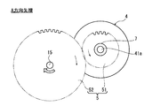
- FIG. 2 is a view in the direction of arrow A in FIG. 1 showing a first gear train of a hybrid drive system to which the shift control device of the first embodiment is applied.
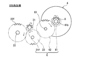
- FIG. 3 is a view in the direction of the arrow B in FIG. 1 showing a second gear train of a hybrid drive system to which the shift control device of the first embodiment is applied.
- It is the schematic which shows an example of the shift actuator which has in the hybrid drive system to which the transmission control apparatus of Example 1 was applied.
- FIG. 1 is an overall configuration diagram illustrating a drive system of a hybrid vehicle to which a transmission control device according to a first embodiment is applied.
- FIG. 2 is a view in the direction of arrow A in FIG. 1 showing a first gear train
- FIG. 3 is a control block diagram illustrating a shift control system in the shift control apparatus for a hybrid vehicle according to the first embodiment. It is a flowchart which shows the structure and flow of a shift control process at the time of the upshift performed by the integrated controller of Example 1. It is a flowchart which shows the structure and flow of a shift control process at the time of the downshift performed by the integrated controller of Example 1.
- FIG. 6 is an operation explanatory diagram illustrating a first one-way clutch engagement operation in the shift control device for a hybrid vehicle according to the first embodiment.
- FIG. 6 is an operation explanatory diagram showing a second one-way clutch fastening operation in the shift control device for a hybrid vehicle of the first embodiment.
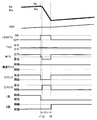
- Engine speed, transmission input shaft speed, vehicle speed, motor / generator, start clutch, first one-way clutch, second one-way clutch, throttle opening, 1 at engine start and start in the hybrid vehicle of the first embodiment It is a time chart which shows each characteristic of a high-speed dog clutch and a 2-speed dog clutch.
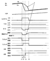
- the engine speed when the engine speed is below a predetermined value, the engine speed at the time of upshifting, the transmission input shaft speed, the vehicle speed, the engine torque down, the throttle opening, the motor / generator, the starting clutch, It is a time chart which shows each characteristic of the 1st one way clutch, the 2nd one way clutch, the 1st speed dog clutch, and the 2nd speed dog clutch.
- the engine speed at the time of upshifting the transmission input shaft speed, the vehicle speed, the engine torque down, the throttle opening, the motor / generator, the starting clutch
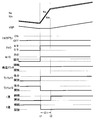
- Engine speed, transmission input shaft speed, vehicle speed, engine torque down, throttle opening, motor / generator, starting clutch, first one-way clutch, second one-way clutch, downshift in the hybrid vehicle of the first embodiment It is a time chart which shows each characteristic of a 1st speed dog clutch and a 2nd speed dog clutch.
- FIG. 1 shows a drive system of a hybrid vehicle to which the shift control device of the first embodiment is applied.
- 2 and 3 show a first gear train and a second gear train of a hybrid drive system to which the transmission control device of the first embodiment is applied.
- the overall configuration of the FF hybrid drive system will be described below with reference to FIGS.
- the drive system of the hybrid vehicle to which the shift control device of the first embodiment is applied includes an engine 1, a gear-type multi-stage transmission 2, a start clutch 3, a motor / generator 4, A gear train 5, a second gear train 6, a first one-way clutch 7, a second one-way clutch 8, a final reduction gear train 9, a differential gear 10, a left drive shaft 11, a right drive shaft 12, A left front wheel 13 (drive wheel) and a right front wheel 14 (drive wheel) are provided.
- the engine 1 is an internal combustion engine such as a gasoline engine or a diesel engine. Based on an engine control command from an engine controller 101 (described later) to an engine actuator 112, engine start control, throttle valve opening control, and fuel cut control. Etc. are performed. A flywheel 16 is provided on the crankshaft 15 of the engine 1.
- the gear-type multi-stage transmission 2 is a transmission called a single clutch type automatic MT in which the shift stage of the manual transmission is automated by a dog clutch mechanism 24 (shift stage selection clutch mechanism).
- a hydraulic-less multi-stage transmission that has five forward speeds and one reverse speed and that performs shift control by a motor actuator without using a hydraulic actuator is employed.
- the gear-type multi-stage transmission 2 is also called a parallel two-shaft multi-stage transmission, and includes a transmission input shaft 21 coaxially arranged with the crankshaft 15, a transmission output shaft 22 arranged parallel to the transmission input shaft 21, and It has.
- the transmission input shaft 21 has a first speed gear 21a, a third speed gear 21b, a second speed gear 21c, a fourth speed gear 21d, a fifth speed gear 21e, and a reverse gear 21f, and each gear 21a, 21b, 21c, 21d, 21e and 21f are provided integrally with the transmission input shaft 21 or fixed integrally with the transmission input shaft 21.
- the transmission output shaft 22 includes a first speed selection gear 22a, a third speed selection gear 22b, a second speed selection gear 22c, a fourth speed selection gear 22d, a fifth speed selection gear 22e, and a reverse selection gear 22f. Accordingly, the fixing to the transmission output shaft 22 is selected.
- the first gear to fifth gear 21a, 21b, 21c, 21d, 21e and the first gear selection gear to fifth gear selection gear 22a, 22b, 22c, 22d, 22e always have a pair of gears combined for each gear. It is in meshing state. However, the reverse gear 21f and the reverse selection gear 22f are engaged with each other via a reverse counter gear 23 for reversing the rotation direction (see FIG. 3). Each of the first to reverse gears is selected by the dog clutch mechanism 24 having no synchro capacity.
- the dog clutch mechanism 24 includes a 1-3 dog clutch mechanism 24a, a 1-3 shift fork 24b, a 2-4 dog clutch mechanism 24c, a 2-4 shift fork 24d, a 5-R dog clutch mechanism 24e, and a 5-R shift. And a fork 24f.
- the 1-3 dog clutch mechanism 24a and the 1-3 shift fork 24b are set at positions between the first speed selection gear 22a and the third speed selection gear 22b, and the transmission output of the first speed selection gear 22a or the third speed selection gear 22b.
- the fixing to the shaft 22 is selected by meshing fitting.
- the 2-4 dog clutch mechanism 24c and the 2-4 shift fork 24d are set at positions between the 2nd speed selection gear 22c and the 4th speed selection gear 22d, and the transmission output of the 2nd speed selection gear 22c or the 4th speed selection gear 22d.
- the fixing to the shaft 22 is selected by meshing fitting.
- the 5-R dog clutch mechanism 24e and the 5-R shift fork 24f are set at a position between the 5-speed selection gear 22e and the reverse selection gear 22f, and the transmission output shaft 22 of the 5-speed selection gear 22e or the reverse selection gear 22f. Is fixed by meshing engagement.
- the starting clutch 3 is a dry friction clutch that is interposed between the crankshaft 15 and the transmission input shaft 21 and connects and disconnects torque transmission between the crankshaft 15 and the transmission input shaft 21.
- the starting clutch 3 has an engagement torque capacity controlled by rotational drive control of the clutch motor 35 based on a control command from a clutch controller 103 to be described later to the clutch motor driver 115.
- the motor / generator 4 is a synchronous motor / generator having a rotor shaft 41, a rotor 42 having a permanent magnet embedded therein, and a stator 43 around which a stator coil is wound.
- the motor / generator 4 can operate as an electric motor that rotates by receiving power supplied from the battery 114 (this operation state is hereinafter referred to as “powering”), and the rotor 42 includes the engine 1 and the left and right front wheels 13. , 14 functions as a generator that generates electromotive force at both ends of the stator coil, and can also charge the battery 114 (hereinafter, this operation state is referred to as “regeneration”).
- a rotor shaft 41 extending in both axial directions from the motor / generator 4 is arranged in parallel to the crankshaft 15 and the transmission input shaft 21.
- the first gear train 5 is a gear train that drives and connects the engine-side first rotor shaft end portion 41 a of the rotor shaft 41 and the crankshaft 15 of the engine 1. As shown in FIGS. 1 and 2, the first gear train 5 is fixed to the first motor gear 51 fixed to the first rotor shaft end 41 a and the crankshaft 15 from the engine 1. And an engine crank gear 52 that meshes with the engine crank gear 52.
- the second gear train 6 extends in the crankshaft direction from the second rotor shaft end portion 41 b on the transmission input shaft side of the rotor shaft 41 and the rear end portion of the transmission input shaft 21, that is, from the engine 1.
- a gear train that connects and drives an end located on the side far from the engine 1.
- the second gear train 6 is disposed in the last train of each speed gear disposed on the transmission input shaft 21, and is reverse gear 21 f (synchronized with the transmission input shaft 21).
- a rear counter gear 23 that meshes with the reverse gear 21f, a second motor gear 61 that is fixed to the second rotor shaft end 41b, and an additional counter shaft 63 that is fixed to the second motor gear 61 and the reverse counter.
- an additional counter gear 62 that meshes with the gear 23 simultaneously.
- the first one-way clutch 7 is interposed between the first rotor shaft end portion 41a and the first motor gear 51 of the first gear train 5, and is composed of an inner race and an outer race (not shown).
- the inner race is fixed to the first rotor shaft end portion 41a, and is a clutch that is fastened by mechanical engagement only when the rotational speed of the inner race is greater than or equal to the rotational speed of the outer race (hereinafter simply referred to as “ It is described as “a clutch that is fastened by mechanical engagement only when the motor rotational speed is equal to or higher than the engine rotational speed”. Note that the first one-way clutch 7 is idled (released) when the inner race rotational speed is less than the outer race rotational speed and the mechanical engagement is released.
- the first one-way clutch 7 is engaged only when torque is transmitted from the motor / generator 4 to the engine 1. Thereby, in the torque transmission between the motor / generator 4 and the engine 1, only the torque from the motor / generator 4 side to the engine 1 side is transmitted.
- the second one-way clutch 8 is interposed between the second rotor shaft end 41b and the second motor gear 61 of the second gear train 6, and is composed of an outer race and an inner race (not shown).
- the inner race is fixed to the second rotor shaft end 41b.
- a clutch that is fastened by mechanical engagement only when the outer race rotation speed is greater than or equal to the inner race rotation speed hereinafter simply referred to as “when the transmission input shaft rotation speed is equal to or higher than the motor rotation speed).
- a clutch that is fastened by mechanical engagement only The second one-way clutch 8 is idled (released) when the mechanical engagement is released when the rotational speed of the outer race is less than the rotational speed of the inner race.
- the second one-way clutch 8 is engaged only when torque is transmitted from the gear type multi-stage transmission 2 to the motor / generator 4. Thereby, in the torque transmission between the gear type multi-stage transmission 2 and the motor / generator 4, only the torque from the gear type multi-stage transmission 2 side to the motor / generator 4 side is transmitted.
- the final reduction gear train 9 includes a transmission output gear 91 provided at an end position of the transmission output shaft 22, a drive output reduction gear 92 that meshes with the transmission output gear 91 and rotates the differential case of the differential gear 10.
- a gear train having The drive output to the differential case of the differential gear 10 is equally distributed to the left and right, transmitted to the left front wheel 13 via the left drive shaft 11, and transmitted to the right front wheel 14 via the right drive shaft 12.
- FIG. 4 shows an example of the starting clutch 3 used in the hybrid drive device of the first embodiment.
- the starting clutch 3 includes a clutch plate 31, an engine-side pressure plate 32, and a transmission-side pressure plate 34.
- the clutch plate 31 is splined to the end position of the transmission input shaft 21. And it is interposed between a fixed engine side pressure plate 32 that is spline-fitted to the crankshaft 15 and a transmission side pressure plate 34 that is movable in the axial direction. That is, among the three plates 31, 32, 34, the clutch releasing state is achieved by releasing the fastening force from the transmission-side pressure plate 34. Then, a clutch fastening state is established by applying a fastening force from the transmission-side pressure plate 34 and closing the gap to integrate the three plates 31, 32, 34.
- the motor actuator that applies the fastening force to the starting clutch 3 is an actuator that is driven without using any hydraulic pressure, and includes a motor 35, a ball screw 36, a spring 37, a roller 38, and an engagement lever 39. Configured. That is, when the ball screw 36 is moved by the motor 35, the roller 38 serving as a fulcrum of the engagement lever 39 moves in the vertical direction in FIG. By this fulcrum movement of the engagement lever 39, a fastening force based on a biasing force by the spring 37 is applied to the first pressure plate 33 and the second pressure plate. As described above, since the output from the motor 35 is not used as the fastening force, there is an advantage that the fastening force can be sufficiently applied to the starting clutch 3 even with a small motor output.
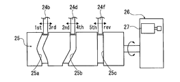
- FIG. 5 shows an example of a shift actuator used in the shift control device for a hybrid vehicle according to the first embodiment.
- the schematic configuration of the shift actuator will be described below with reference to FIG.
- the shift actuator moves the 1-3 shift fork 24b, the 2-4 shift fork 24d, and the 5-R shift fork 24f in the axial direction according to the position of the selected gear position. 26.
- the cylindrical drum 25 has a 1-3 shift cam groove 25a for guiding the axial movement of the 1-3 shift fork 24b, a 2-4 shift cam groove 25b for guiding the axial movement of the 2-4 shift fork 24d, and 5
- a 5-R shift cam groove 25c for guiding the axial movement of the -R shift fork 24f is formed along the cylindrical surface.
- the motor mechanism 26 decelerates the shift motor 27 using a DC motor and rotates the cylindrical drum 25 according to the selected gear position.
- the rotation of the cylindrical drum 25 causes the shift cam grooves 25a so that the 1-3 shift fork 24b, the 2-4 shift fork 24d, and the 5-R shift fork 24f are switched from the speed stage before selection to the speed stage after selection. , 25b, 25c along the axial direction.
- the three shift forks 24b, 24d, and 24f are driven by one motor mechanism 26, there is an advantage that the configuration of the shift actuator can be simplified.
- FIG. 6 shows a shift control system in the shift control apparatus for the hybrid vehicle of the first embodiment.
- the shift control system in the shift control apparatus for a hybrid vehicle includes an integrated controller 100, an engine controller 101, a motor controller 102, a clutch controller 103, and a shift controller 104. ing. These controllers 100, 101, 102, 103, and 104 are connected to be able to exchange information through a bidirectional communication line 105 such as a CAN communication line.
- a bidirectional communication line 105 such as a CAN communication line.
- the integrated controller 100 receives switch signals and sensor signals from an ignition key switch 106, an engine speed sensor 107, a transmission input shaft rotation sensor 108, a transmission output shaft rotation sensor 109, a throttle opening sensor 110, a vehicle speed sensor 111, and the like. input. Then, based on these input information, the dog / clutch mechanism performs the engine start control for starting the engine 1 using the motor / generator 4 as a starter motor, the start control for increasing the engagement torque capacity of the start clutch 3 in the first speed state, and the switching of the shift stage. The shift control performed by 24 is executed.
- the engine controller 101 When the engine controller 101 receives a control command from the integrated controller 100 via the bidirectional communication line 105, the engine controller 101 outputs a control signal based on the control command to the engine actuator 112.
- a control command is received from the integrated controller 100 during upshifting, engine torque down control is performed by retard or fuel cut.
- the electronic throttle is quickly opened.
- the motor controller 102 When the motor controller 102 receives a control command from the integrated controller 100 via the bidirectional communication line 105, the motor controller 102 outputs a control signal based on the control command to the inverter 113.
- the rotational speed of the motor / generator 4 When a control command is received from the integrated controller 100 during upshifting, the rotational speed of the motor / generator 4 is controlled to set the rotational speed of the engine 4 to the target engine rotational speed or the rotational speed of the transmission input shaft 21 to the target. Regenerative control (rotational speed control) is performed to match the transmission input shaft rotational speed.
- the engine torque canceling control for canceling the engine torque transmitted by the dog clutch by the power running control during coasting and the regenerative control during driving, and the motor / generator 4 Power running control (rotational speed control) is performed to match the rotational speed of the engine 4 with the target engine rotational speed by controlling the rotational speed of the engine.
- the clutch controller 103 When the clutch controller 103 receives a control command from the integrated controller 100 via the bidirectional communication line 105, the clutch controller 103 outputs a control signal based on the control command to the clutch motor driver 115.
- a control command is received from the integrated controller 100 at the time of upshifting or downshifting when the engine speed Ne is equal to or less than a predetermined value Ne1, control is performed to maintain the engagement torque capacity of the starting clutch 3.
- a control command is received from the integrated controller 100 during an upshift where the engine speed Ne exceeds a predetermined value Ne1
- clutch capacity zero control is performed, and when the dog clutch is released / engaged, clutch capacity increase control is performed.
- the shift controller 104 When the shift controller 104 receives a control command from the integrated controller 100 via the bidirectional communication line 105, the shift controller 104 outputs a control signal based on the control command to the shift motor driver 116.
- the clutch release control When a control command is received from the integrated controller 100 at the time of upshifting or downshifting, the clutch release control for releasing the dog clutch engaged at the gear stage before the gear shift and the dog clutch released at the gear stage after the gear shift are engaged. Clutch engagement control is performed.
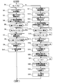
- FIG. 7 shows a configuration and a flow of a shift control process at the time of upshift executed by the integrated controller 100 of the first embodiment (shift control means).
- This upshift control process is started while giving the starting clutch 3 a fastening torque capacity in response to an upshift command issued when the operating point (TVO, VSP) on the shift map crosses the upshift line.
- step S1 it is determined whether or not the engine speed Ne is equal to or less than a predetermined value Ne1. If YES (Ne ⁇ Ne1), the process proceeds to step S2, and if NO (Ne> Ne1), the process proceeds to step S11.
- the predetermined value Ne1 is a value determined by the inertia of (engine 1 + starting clutch 3 + transmission input shaft 21) and the output value (wattage) of the motor / generator 4. Specifically, after the rotation synchronization control by the regenerative control of the motor / generator 4 is started, the engine rotation speed becomes the target engine rotation speed Ne * (n + 1) after the upshift, and the rotation synchronization control ends.
- the engine speed Ne is set so that the time required until the time becomes a desired time (for example, 0.2 sec).
- step S2 following the determination that Ne ⁇ Ne1 in step S1, engine torque down control that prompts the dog clutch engaged in n-speed to be released is started, and the process proceeds to step S3.
- step S3 following the start of engine torque reduction control in step S2, a command to release the dog clutch engaged at the nth speed is output, and the process proceeds to step S4.
- step S4 following the n-speed dog clutch release command in step S3, the motor / generator 4 under power running control is temporarily set to the neutral state, and then regeneration control by the motor / generator 4 is started, and the process proceeds to step S5. .
- the start of the regenerative control of the motor / generator 4 means the start of the rotation synchronous control in which the engine speed Ne at the start of the upshift is decreased and matched with the target engine speed Ne * (n + 1) after the upshift . To do.
- step S5 following the start of motor regeneration control in step S4, it is determined whether or not the release of the dog clutch engaged at the n-th speed has been completed. If YES (n-speed dog clutch release complete), the process proceeds to step S6. If NO (n-speed dog clutch release complete), the determination in step S5 is repeated.
- step S6 following the determination in step S5 that the n-speed dog clutch release is complete, the absolute value of the difference between the actual engine speed Ne at that time and the target engine speed Ne * (n + 1) after the upshift . Is less than the set deviation ⁇ 1. If YES (
- the set deviation ⁇ 1 is a value at which the actual engine speed Ne is substantially close to the target engine speed Ne * (n + 1), and the engagement command may be issued to the dog clutch that is engaged at the (n + 1) speed. Set to the rotation value.
- step S7 following the determination that
- step S8 following the (n + 1) -speed dog clutch engagement command in step S7, it is determined whether or not (n + 1) -speed dog clutch engagement is complete. If YES ((n + 1) -speed dog clutch engagement complete), the process proceeds to step S9. If NO ((n + 1) -speed dog clutch engagement is incomplete), the determination in step S8 is repeated.
- step S9 following the determination that the (n + 1) -speed dog clutch engagement is completed in step S8, the engine torque down control is terminated, and the process proceeds to step S10.
- step S10 following the end of the engine torque reduction control in step S9, the motor regeneration control ends, and the process proceeds to the end.
- step S11 following the determination that Ne> Ne1 in step S1, clutch capacity zero control for starting the clutch capacity of the starting clutch 3 maintaining the engagement torque capacity is started, and the process proceeds to step S12.
- This clutch capacity zero control refers to control that causes the torque transmission amount to become zero by slipping the starting clutch 3 so that the clutch 3 is slipped.
- This clutch capacity zero control prompts the dog clutch that is engaged at the n-th speed to be released.
- step S12 engine torque down control is started following the start of clutch capacity zero control in step S11, and the process proceeds to step S13.
- step S13 following the start of engine torque reduction control in step S12, a command to release the dog clutch engaged at the n-th speed is output, and the process proceeds to step S14.
- step S14 following the n-speed dog clutch release command in step S13, the motor / generator 4 under power running control is temporarily set to the neutral state, and then regeneration control by the motor / generator 4 is started, and the process proceeds to step S15.
- the start of the regenerative control of the motor / generator 4 reduces the transmission input shaft rotational speed Nin at the start of the upshift, and rotates it to match the target transmission input shaft rotational speed Nin * (n + 1) after the upshift . It means the start of synchronous control.
- step S15 following the start of the motor regeneration control in step S14, it is determined whether or not the release of the dog clutch engaged at the n-th speed is completed. If YES (n-speed dog clutch release complete), the process proceeds to step S16. If NO (n-speed dog clutch release complete), the determination in step S15 is repeated.
- step S16 following the determination that the n-speed dog clutch release is complete in step S15, the actual transmission input shaft rotational speed Nin at that time and the target transmission input shaft rotational speed Nin * (n + 1) after the upshift are performed . ) Is determined as to whether or not the absolute value of the difference is less than the set deviation ⁇ 1 ′. If YES (
- the set deviation ⁇ 1 ′ is a value at which the actual transmission input shaft rotational speed Nin is substantially close to the target transmission input shaft rotational speed Nin * (n + 1), and is engaged with the dog clutch that is engaged at the (n + 1) speed. It is set to a small rotation value at which a command can be issued.
- step S17 following the determination that
- step S18 following the (n + 1) -speed dog clutch engagement command in step S17, it is determined whether or not (n + 1) -speed dog clutch engagement is complete. If YES ((n + 1) -speed dog clutch engagement complete), the process proceeds to step S19. If NO ((n + 1) -speed dog clutch engagement is incomplete), the determination in step S18 is repeated.
- step S19 following the determination that the (n + 1) -speed dog clutch engagement is complete in step S18, the clutch capacity zero control is terminated, and the process proceeds to step S20.
- step S20 following the end of clutch capacity zero control in step S19, control is performed to increase the clutch capacity in accordance with the deviation e so as to gradually decrease the deviation e, which is the rotational speed difference (slip amount) of the starting clutch 3.
- the deviation e is calculated from the absolute value of the difference between the engine speed Ne and the transmission input shaft speed Nin.
- step S21 following the start of clutch capacity control according to the deviation e in step S20, it is determined whether or not the deviation e is less than the set deviation ⁇ 2. If YES (e ⁇ 2), the process proceeds to step S22. If NO (e ⁇ ⁇ 2), the determination in step S21 is repeated.
- the set deviation ⁇ 2 is set to a small value that does not cause a shift shock even when the start clutch 3 is shifted to the fully engaged state.
- step S22 following the determination that e ⁇ 2 in step S21, the clutch capacity control is terminated, and the process shifts to complete engagement control in which the starting clutch 3 is engaged without slipping, and the process proceeds to step S23.
- step S23 following the end of the clutch capacity control of the starting clutch 3 in step S22, the engine torque down control is ended, and the process proceeds to step S24.
- step S24 following the end of the engine torque reduction control in step S23, the motor regeneration control is ended, and the process proceeds to the end.
- FIG. 8 shows the configuration and flow of a shift control process at the time of a down shift executed by the integrated controller 100 of the first embodiment (shift control means).
- This downshift control process is started while giving the starting clutch 3 a fastening torque capacity in response to a downshift command issued when the operating point (TVO, VSP) on the shift map crosses the downshift line.
- step S31 engine torque canceling control by powering control or regenerative control of the motor / generator 4 is started, and the process proceeds to step S32.
- the engine torque canceling control refers to control that prompts the dog clutch to be released by canceling (cancelling) the engine torque transmitted by the dog clutch that is engaged at the n-th speed.
- engine torque cancellation is performed by powering control of the motor / generator 4.
- driving by depressing the accelerator engine torque cancellation is performed by regenerative control of the motor / generator 4.
- step S32 following the start of the engine torque cancel control in step S31, a release command for the dog clutch engaged at the n-th speed is output, and the process proceeds to step S33.
- step S33 following the n-speed dog clutch release command in step S32, it is determined whether or not the release of the dog clutch engaged in n-speed is completed. If YES (n-speed dog clutch release complete), the process proceeds to step S34. If NO (n-speed dog clutch release complete), the determination in step S33 is repeated.
- step S34 following the determination that the n-speed dog clutch release is completed in step S33, the engine torque canceling control is terminated, and the process proceeds to step S35.
- step S35 following the end of the engine torque cancellation control in step S34, the power running control by the motor / generator 4 is started, and the process proceeds to step S36.
- the start of the power running control of the motor / generator 4 means the start of the rotation synchronization control that increases the engine speed Ne at the start of the downshift and matches the target engine speed Ne * (n-1) after the downshift. To do.
- control for quickly opening the electronic throttle of the engine 1 is performed so that rotation synchronization is performed quickly.
- step S36 following the start of motor power running control in step S35, the absolute value of the difference between the actual engine speed Ne at that time and the target engine speed Ne * (n-1) after the downshift is less than the set deviation ⁇ . Judge whether there is. If YES (
- the set deviation ⁇ is a value at which the actual engine speed Ne is substantially close to the target engine speed Ne * (n ⁇ 1), and even if an engagement command is issued to the dog clutch that is engaged at the (n ⁇ 1) speed. Set to a good small rotation number.
- step S37 following the determination that
- step S38 following the (n-1) speed dog clutch engagement command in step S37, it is determined whether or not (n-1) speed dog clutch engagement is complete. If YES (completion of (n-1) -speed dog clutch engagement), the process proceeds to step S9. If NO ((n-1) -speed dog clutch engagement is incomplete), the determination in step S38 is repeated.
- step S39 following the determination that the (n-1) speed dog clutch engagement is complete in step S38, the motor power running control is terminated and the process proceeds to the end.
- the effects of the shift control device of the hybrid vehicle of the first embodiment are “power running control action by engaging the first one-way clutch”, “regeneration control action by engaging the second one-way clutch”, “up-shifting action in the low engine speed range”, The explanation will be divided into “upshifting action in the high engine speed range” and “downshifting action”.
- the first one-way clutch 7 is interposed at one end of the rotor shaft 41 of the motor / generator 4 and the second one-way clutch 8 is interposed at the other end.
- the power running control action by the engagement of the first one-way clutch 7 will be described.
- Power assist power running control action For example, at the time of starting or during intermediate acceleration, it is necessary to assist the driving force of the engine 1 with the driving force of the motor / generator 4 (power assist).
- power assist power running control is performed in which the motor / generator 4 is subjected to power running control (torque control) while the start clutch 3 is engaged.
- the power running energy from the rotor shaft 41 of the motor / generator 4 by this power running control is transmitted from the first one-way clutch 7 ⁇ the first motor gear 51 ⁇ the engine crank gear 52 ⁇ the crankshaft 15 to the driving force from the engine 1, Driving force from the motor / generator 4 is applied.
- the combined driving force passes through the starting clutch 3 and is transmitted to the transmission input shaft 21.
- FIG. 11 is a time chart showing characteristics at the time of engine start and start in the hybrid vehicle of the first embodiment. Hereinafter, the engine start / start control action will be described with reference to FIG. To do.
- the first one-way clutch 7 is interposed at one end of the rotor shaft 41 of the motor / generator 4 and the second one-way clutch 8 is interposed at the other end.
- the regeneration control action by the engagement of the second one-way clutch 8 will be described.
- Engine energy regenerative control action For example, when the battery charge capacity decreases during traveling, the battery 114 needs to be charged using a part of the engine energy.
- engine energy regeneration control for performing regeneration control (torque control) of the motor / generator 4 with the start clutch 3 engaged is executed. Therefore, a part of the energy from the crankshaft 15 of the engine 1 is generated by the starting clutch 3 ⁇ the transmission input shaft 21 ⁇ the reverse gear 21f ⁇ the reverse counter gear 23 ⁇ the additional counter gear 62 ⁇ the second motor gear 61 ⁇ the second one-way clutch 8 ⁇ Transmitted to the rotor shaft 41.
- the motor / generator 4 captures a part of the engine energy as regenerative energy, and charges the electric power obtained by the power generation by the motor / generator 4 as the charging power for the battery 114. That is, the motor / generator 4 exhibits an engine energy regeneration function that takes in part of the engine energy as regenerative energy, and the battery 114 can be charged as necessary during traveling.
- coast energy regenerative control action For example, when decelerating by an accelerator release operation, or when decelerating and stopping, regenerating coast energy to give regenerative braking force to driving wheels leads to improved fuel efficiency.
- coasting energy regeneration control is performed in which the starting clutch 3 is released and the motor / generator 4 is subjected to regeneration control (torque control). Therefore, the coast energy from the left and right front wheels 13 and 14 is changed from the drive shafts 11 and 12 to the differential gear 10 ⁇ the final reduction gear train 9 ⁇ the transmission output shaft 22 ⁇ the meshing gear at the selected stage ⁇ the transmission input shaft 21 ⁇ the reverse gear.
- the motor / generator 4 takes in coast energy from the left and right front wheels 13 and 14 by coast running as regenerative energy, and charges the electric power obtained by the power generation by the motor / generator 4 as charging power to the battery 114. That is, the motor / generator 4 exhibits a coast energy regeneration function that takes in coast energy from the left and right front wheels 13 and 14 by coast traveling as regeneration energy, and the battery 114 can be charged during coast traveling.
- step S5 When it is determined in step S5 that the dog clutch that has been engaged at the n-th speed has been released, the process proceeds from step S5 to the next step S6.
- step S6 it is determined whether or not the absolute value of the difference between the actual engine speed Ne and the target engine speed Ne * (n + 1) after the upshift is less than the set deviation ⁇ 1. That is, the completion of rotation synchronization is determined when the actual engine speed Ne is reduced to a value close to the target engine speed Ne * (n + 1) by the regeneration control of the motor / generator 4. If it is determined in step S6 that the rotation synchronization during the upshift is completed, the process proceeds from step S6 to step S7 to step S8. In step S7, a clutch engagement command is issued to the released (n + 1) speed dog clutch. In step S8, it is determined whether or not the engagement of the (n + 1) speed dog clutch is completed.
- step S8 When it is determined in step S8 that the (n + 1) -speed dog clutch is completely engaged, the process proceeds from step S8 to step S9 ⁇ step S10 ⁇ end.
- step S9 the engine torque reduction control is terminated, and in step S10, the motor regeneration control is terminated.
- the upshift control process in the low engine speed range is performed according to the above processing flow.
- the rotation synchronous control by the regenerative control of the motor / generator 4 is performed by the cooperation of the motor / generator 4 and the engine 1 which are in a drive-coupled state when the start clutch 3 is engaged, so that the time required to reach the synchronous rotational speed is shortened. Is done. That is, the brake torque due to the power generation load acts on the rotor shaft 41 by the regeneration control of the motor / generator 4. The brake torque of the rotor shaft 41 is transmitted to the second one-way clutch 8 ⁇ the second motor gear 61 ⁇ the additional counter gear 62 ⁇ the reverse counter gear 23 ⁇ the reverse gear 21 f ⁇ the transmission input shaft 21 ⁇ the starting clutch 3 ⁇ the crankshaft 15. Is done.
- the upshift control in the low engine speed range is performed by quickly releasing the clutch and quickly engaging the clutch while providing the starting clutch 3 with the engagement torque capacity. For this reason, at the time of upshifting in the low engine speed range, only a short time from the release of the n-speed dog clutch to the engagement of the (n + 1) -speed dog clutch results in the torque being cut off, and the feeling of idling due to the torque cut is suppressed to a small level.
- the upshifting action in the engine low speed range will be described with reference to the time chart of FIG.
- the torque reduction control of the engine 1 is started at time t1 and the power running control of the motor / generator 4 is released, the first one-way clutch 7 is released, and the first-speed dog clutch engaged at the first speed is released.
- the second one-way clutch 8 is engaged, and the actual engine speed Ne is set to the second target engine speed between time t2 and time t3.
- Rotation synchronous control is performed to pull down toward the number Ne * (n + 1).
- step S11 clutch capacity zero control for starting the clutch capacity of the starting clutch 3 is started, and in step S12, engine torque down control is started.
- step S13 a release command for the dog clutch engaged at the n-th speed is output, and in step S14, regeneration control is started after a temporary neutral state has elapsed.
- step S15 it is determined whether or not the release of the dog clutch engaged at the n-th speed is completed.
- step S15 it is determined whether or not the absolute value of the difference between the actual transmission input shaft rotational speed Nin and the target transmission input shaft rotational speed Nin * (n + 1) after the upshift is less than the set deviation ⁇ 1 ′. Is done. That is, the completion of rotation synchronization is determined when the actual transmission input shaft rotational speed Nin decreases to a value close to the target transmission input shaft rotational speed Nin * (n + 1) by the regeneration control of the motor / generator 4.
- step S16 If it is determined in step S16 that the rotation synchronization during the upshift is completed, the process proceeds from step S16 to step S17 to step S18.
- step S17 a clutch engagement command is issued to the opened (n + 1) speed dog clutch.
- step S18 it is determined whether or not the engagement of the (n + 1) -speed dog clutch is completed.
- step S18 When it is determined in step S18 that the (n + 1) -speed dog clutch is completely engaged, the process proceeds from step S18 to step S19 ⁇ step S20 ⁇ step S21.
- step S19 the clutch capacity zero control is terminated, and in step S20, control is performed to increase the clutch capacity in accordance with the deviation e so as to gradually reduce the deviation e, which is the rotational speed difference (slip amount) of the starting clutch 3.
- step S21 it is determined whether or not the deviation e is less than the set deviation ⁇ 2.
- step S21 When it is determined in step S21 that the deviation e is less than the set deviation ⁇ 2, the process proceeds from step S21 to step S22 ⁇ step S23 ⁇ step S24 ⁇ end.
- step S22 the clutch capacity control is finished, and the starting clutch 3 is brought into a completely engaged state without slipping.
- step S23 the engine torque down control is finished, and in step S24, the motor regeneration control is finished.
- the upshift control process in the high engine speed range is performed according to the above processing flow.
- the rotation synchronization control by the regenerative control of the motor / generator 4 is instantaneously performed between the motor / generator 4 and the transmission input shaft 21 which are in a drive-connected state by opening the start clutch 3. That is, the brake torque due to the power generation load acts on the rotor shaft 41 by the regeneration control of the motor / generator 4.
- the brake torque of the rotor shaft 41 is transmitted from the second one-way clutch 8 ⁇ the second motor gear 61 ⁇ the additional counter gear 62 ⁇ the reverse counter gear 23 ⁇ the reverse gear 21f ⁇ the transmission input shaft 21.
- the brake torque from the rotor shaft 41 of the motor / generator 4 changes the rotational speed of the transmission input shaft 21 (actual transmission input shaft rotational speed Nin) to the target transmission input shaft rotational speed Nin * (n + after the upshift .
- Rotational synchronization control is performed to instantaneously pull down to a value close to 1).
- the clutch capacity control that gives the clutch capacity from the zero capacity control of the start clutch 3 is performed by gradually increasing the clutch capacity while monitoring the deviation e which is the slip amount of the start clutch 3. For this reason, after the (n + 1) -speed dog clutch is engaged, the driving force transmitted to the driving wheels is gradually recovered while suppressing the decreasing gradient of the engine speed Ne.
- the upshift control in the high engine speed range is performed by the clutch capacity zero control of the start clutch 3, the quick clutch release and quick clutch engagement of the dog clutch mechanism, and the clutch capacity increase control of the start clutch 3. .
- the predetermined value Ne1 of the engine speed Ne is an engine speed Ne at which a time required from the start of the rotation synchronization control by the regeneration control of the motor / generator 4 to the end of the rotation synchronization control becomes a desired time (for example, 0.2 sec). Is set. For example, in the high engine speed range where the engine speed Ne exceeds a predetermined value Ne1, if the up-shift control of the engine low speed range is performed, rotation synchronization is required to reduce the high engine speed to the synchronous speed. The time becomes longer, and the feeling of free running due to running out of torque appears.
- the upshift control in the high engine speed range is the rotation synchronization control with the zero displacement control of the starting clutch 3, thereby eliminating the influence of engine inertia that lengthens the time required for rotation synchronization. For this reason, the idling feeling due to running out of torque can be suppressed to a small level while performing the upshift control in the high engine speed range.
- step S31 engine torque cancellation control by powering control or regenerative control of the motor / generator 4 is started.
- step S32 a release command for the dog clutch engaged at the nth speed is output, and in step S33, it is determined whether or not the release of the dog clutch engaged at the nth speed is completed.
- step S33 When it is determined in step S33 that the dog clutch engaged at the n-th speed has been released, the process proceeds from step S33 to step S34 ⁇ step S35 ⁇ step S36.
- step S34 the engine torque canceling control is terminated, and in step S35, the power running control by the motor / generator 4 is started.
- step S36 it is determined whether or not the absolute value of the difference between the actual engine speed Ne at that time and the target engine speed Ne * (n-1) after the downshift is less than the set deviation ⁇ . That is, the completion of rotation synchronization is determined when the actual engine speed Ne increases to a value close to the target engine speed Ne * (n ⁇ 1) by the power running control of the motor / generator 4.
- step S36 If it is determined in step S36 that the rotation synchronization during the downshift has been completed, the process proceeds from step S36 to step S37 to step S38.
- step S37 a clutch engagement command is issued to the opened (n-1) speed dog clutch.
- step S38 it is determined whether or not the (n-1) -speed dog clutch is completely engaged.
- step S38 When it is determined in step S38 that the (n ⁇ 1) -speed dog clutch is completely engaged, the process proceeds from step S38 to step S39, where the motor power running control is terminated.
- the downshift control process is performed according to the above processing operation flow.
- the above-mentioned release control of the dog clutch engaged at the n-th speed starts the engine torque canceling control when the downshift is started.
- the motor / generator 4 is performing regenerative control at the start of downshifting
- switching to power running control is engine torque cancellation control. Therefore, the torque in the meshing release direction due to the engine torque cancellation cancels the torque acting in the meshing direction of the dog clutch, and the dog clutch engagement is quickly released.
- the rotation synchronization control by the power running control of the motor / generator 4 is performed in cooperation with the engine 1 that is in a drive-coupled state by the engagement of the start clutch 3, so that the time required to reach the synchronous rotation speed is shortened. That is, the driving torque by the motor driving acts on the rotor shaft 41 by the power running control of the motor / generator 4.
- the driving torque of the rotor shaft 41 is transmitted from the first one-way clutch 7 ⁇ the first motor gear 51 ⁇ the engine crank gear 52 ⁇ the crankshaft 15.
- the downshift control is performed by quickly releasing the clutch and quickly engaging the dog clutch mechanism while providing the starting clutch 3 with the engagement torque capacity. For this reason, at the time of downshift, only a short time from the release of the n-th dog clutch to the engagement of the (n-1) -th dog clutch causes the torque to run out.
- the downshift operation will be described with reference to the time chart of FIG.
- the throttle opening TVO is opened to the full open range by the accelerator depression operation
- the power running control of the motor / generator 4 is started, the second one-way clutch 8 is released, and the first one-way clutch 7 is engaged.
- the second-speed dog clutch that is engaged at the second speed is released.
- the throttle opening TVO is opened to the fully open range by the accelerator depressing operation at time t1
- the actual engine speed between time t1 and time t2 is achieved by the power running control of the motor / generator 4 and the quick opening of the electronic throttle.
- Rotation synchronous control is performed to raise Ne toward the first engine speed Ne * (n-1).
- Engine 1 and A motor / generator 4 A gear type multi-stage transmission 2 in which the shift of gears is automated by a gear selection clutch mechanism (dog clutch mechanism 24); A starting clutch 3 for connecting and disconnecting torque transmission from the engine 1 to the driving wheels (the left and right front wheels 13, 14); Shift control means (FIGS. 7 and 8) for controlling the shift stage of the gear type multi-stage transmission 2;
- a shift control device for a hybrid vehicle comprising: The motor / generator 4 is capable of power running and regeneration with respect to a driving force transmission system from the crankshaft 15 of the engine 1 to the transmission input shaft 21 of the gear type multi-stage transmission 2 via the starting clutch 3. age, The shift control means (FIGS.
- the gear type multi-stage transmission 2 uses a dog clutch mechanism 24 as a gear selection clutch mechanism for switching gears.
- the shift control means (FIG. 7) performs a first up shift control in response to an up shift command for switching the shift stage to the high speed stage (steps S2 to S10).
- the rotation speed Ne of the engine 1 is increased by the regeneration control of the motor / generator 4 while the starting clutch 3 has a fastening torque capacity, and the target engine speed Ne * ( n + 1) is performed, and after the clutch release control of the dog clutch mechanism 24 is completed, when the engine rotation synchronization state is confirmed, the clutch engagement control of the dog clutch mechanism 24 is performed.
- the shift control means (FIG. 7) performs the second upshift control in response to the upshift command when the rotational speed of the engine 1 when the upshift command exceeds the predetermined value N1.
- the second upshift control includes a zero control that makes the engagement torque capacity of the start clutch 3 zero, and a regenerative control of the motor / generator 4 to reduce the rotational speed Nin of the transmission input shaft 21 to the target after the upshift.
- the shift control means rotates after the engine rotation synchronization control is started and the rotation speed Ne of the engine 1 becomes the target engine rotation speed Ne * (n + 1) after the upshift.
- the engine speed Ne at which the time required until the end of the synchronization control is a desired time is set as a predetermined value Ne1, and the engine speed Ne when the upshift command is issued is equal to or less than the predetermined value Ne1. (YES in step S1), the first upshift control is executed (steps S2 to S10).
- the gear-type multi-stage transmission 2 uses a dog clutch mechanism 24 as a gear selection clutch mechanism for switching gears.
- the shift control means (FIG. 8), in response to a downshift command for switching the shift speed to the low speed position, gives the starting clutch 3 a fastening torque capacity and reverses the direction of the torque that rotates the dog clutch mechanism 24.
- Engine torque canceling control for applying the torque of the dog clutch mechanism 24 by the motor / generator 4 is started. After completion, engine rotation synchronization control is started by setting the rotation speed Ne of the engine 1 to the target engine rotation speed Ne * (n-1) after downshifting by the power running control of the motor / generator 4.
- the motor / generator 4 has a rotor shaft 41 extending in both axial directions in a parallel arrangement parallel to the crankshaft 15 and the transmission input shaft 21.
- the two gear trains 6 and the second one-way clutch 8 that is engaged when torque is transmitted from the transmission input shaft 21 to the motor / generator 4 are connected in a connectable manner.
- the motor / generator 4 the first gear train 5 and the second gear train 6 can be added to the engine 1 without increasing costs or increasing space. It is possible to set the motor / generator 4 capable of powering and regenerating the driving force transmission system that reaches the transmission input shaft 21.
- the starting clutch 3 is provided between the crankshaft 15 of the engine 1 and the transmission input shaft 21,
- the first gear train 5 is A first motor gear 51 disposed at the first rotor shaft end 41a;
- An engine crank gear 52 that is disposed on the crankshaft 15 and meshes with the first motor gear 51
- the second gear train 6 is A second motor gear 61 disposed at the second rotor shaft end 41b;
- the rear end is disposed at a position farthest from the engine 1 and meshes with the second motor gear 61.
- a gear (reverse gear 21f) is provided.
- the motor / generator 4 can have an elongated configuration corresponding to the axial length of the gear-type multi-stage transmission 2, and as a result, when the engine is driven without increasing the space.
- the motor inertia which becomes a load can be suppressed small.
- the gear-type multi-stage transmission 2 has a transmission output shaft 22 that receives torque from the transmission input shaft 21 and shifts and transmits the torque to drive wheels.
- the first gear train 5 is An engine crank gear 52 disposed on the crankshaft 15; A first motor gear 51 disposed at the first rotor shaft end 41a and meshing with the engine crank gear 52;
- the second gear train 6 is A reverse gear 21f disposed on the transmission input shaft 21 and rotating synchronously with the transmission input shaft 21; A reverse counter gear 23 that meshes with the reverse gear 21f and transmits a torque input to the transmission input shaft 21 to the transmission output shaft 22 by changing a rotation direction;
- An additional counter gear 62 meshing with the reverse counter gear 23;
- the second motor gear 61 is arranged at the second rotor shaft end portion 41 b and meshes with the additional counter gear 62.
- the power / running of the motor / generator 4 can be achieved by adding only one additional counter gear 62 by using the reverse gear 21f and the reverse counter gear 23 as a part of the second gear train 6. And the rotation direction of regeneration can be matched.
- the reverse gear 21f is a rear end disposed at a position farthest from the engine 1 among the plurality of gears 21a, 21b, 21c, 21d, 21e, and 21f disposed on the transmission input shaft 21. It is a gear. Therefore, in addition to the effect of (8), the reverse gear 21f and the reverse counter gear 23 are used as a part of the second gear train 6, and the motor / generator 4 is arranged along the axial direction of the gear type multi-stage transmission 2. By adopting the arrangement, it is possible to configure the hybrid drive device while minimizing the number of parts and space increase from the existing engine 1 + gear type multi-stage transmission 2.
- an example of a multi-stage transmission having five forward speeds and one reverse speed is shown as the gear type multi-stage transmission 2.
- the gear-type multi-stage transmission is capable of switching between a plurality of shift speeds, the specific shift speed is not limited to the fifth forward speed / first reverse speed of the first embodiment.
- the motor / generator 4 is set without causing an increase in cost or space.
- the motor / generator is set to enable power running and regeneration with respect to the driving force transmission system from the engine crankshaft through the starting clutch to the transmission input shaft of the gear type multi-stage transmission. Not limited to settings.
- gear selection operation actuator of the gear type multi-stage transmission 2 an example in which a motor actuator suitable for reducing hydraulic pressure is used as the gear selection operation actuator of the gear type multi-stage transmission 2 is shown.
- another actuator such as an electromagnetic actuator or a hydraulic actuator may be used as the gear selection actuator.
- the start clutch type may be a dry type or a wet type, and may be a single plate type or a multi-plate type.
- the first one-way clutch 7 is used as the first clutch
- the second one-way clutch 8 is used as the second clutch.
- an electromagnetic clutch, a hydraulic clutch, or the like that is connected / disconnected by an external command may be used.
- Example 1 shows an example in which the reverse gear 21f is used as the rear end gear.
- a gear other than the reverse gear may be used as long as the gear rotates in synchronization with the transmission input shaft even if it is not arranged in the last row of the transmission input shaft of the gear type multi-stage transmission.
- Embodiment 1 shows an example in which the shift control device for a hybrid vehicle of the present invention is applied to a drive system of an FF hybrid vehicle.
- the shift control device for a hybrid vehicle of the present invention can be applied to a drive system of an FR hybrid vehicle, a drive system of a 4WD hybrid vehicle, and the like.
Abstract
L'invention porte sur un appareil de commande de changement pour un véhicule hybride dans lequel un moyen de commande de changement exécute, en réponse à un ordre de changement et pendant que l'embrayage de démarrage (3) possède une capacité de couple de serrage : une commande de débrayage pour un mécanisme d'embrayage à crabot (24) ; une commande de synchronisation de la rotation du moteur thermique par commande à récupération ou une commande d'alimentation d'un moteur/générateur (4) ; et une commande de serrage de l'embrayage pour le mécanisme d'embrayage à crabot (24) de manière à sélectionner un niveau de changement après changement dans un état synchronisé de la rotation du moteur thermique dans lequel la vitesse de rotation (Ne) du moteur thermique (1) est une vitesse de rotation du moteur thermique cible après changement.
Applications Claiming Priority (2)
| Application Number | Priority Date | Filing Date | Title |
|---|---|---|---|
| JP2011-115359 | 2011-05-24 | ||
| JP2011115359A JP2014168966A (ja) | 2011-05-24 | 2011-05-24 | ハイブリッド車両の変速制御装置 |
Publications (1)
| Publication Number | Publication Date |
|---|---|
| WO2012160912A1 true WO2012160912A1 (fr) | 2012-11-29 |
Family
ID=47216996
Family Applications (1)
| Application Number | Title | Priority Date | Filing Date |
|---|---|---|---|
| PCT/JP2012/060650 WO2012160912A1 (fr) | 2011-05-24 | 2012-04-20 | Appareil de commande de changement pour un véhicule hybride |
Country Status (2)
| Country | Link |
|---|---|
| JP (1) | JP2014168966A (fr) |
| WO (1) | WO2012160912A1 (fr) |
Cited By (5)
| Publication number | Priority date | Publication date | Assignee | Title |
|---|---|---|---|---|
| CN111791876A (zh) * | 2020-07-30 | 2020-10-20 | 重庆青山工业有限责任公司 | 基于序列式混动变速器同步器挂挡控制方法 |
| CN112406497A (zh) * | 2020-11-19 | 2021-02-26 | 北京汽车股份有限公司 | 双电机的扭矩矢量控制系统、方法、动力总成及车辆 |
| CN114739554A (zh) * | 2022-04-02 | 2022-07-12 | 中国第一汽车股份有限公司 | 一种四驱车传动系扭转强度测试实验方法和评价方法 |
| CN114909467A (zh) * | 2021-02-07 | 2022-08-16 | 广汽埃安新能源汽车有限公司 | 一种车辆升挡控制方法、装置及存储介质 |
| EP4023515A4 (fr) * | 2019-08-28 | 2022-08-24 | NISSAN MOTOR Co., Ltd. | Dispositif de transmission de puissance |
Families Citing this family (4)
| Publication number | Priority date | Publication date | Assignee | Title |
|---|---|---|---|---|
| EP3051183A1 (fr) * | 2015-01-28 | 2016-08-03 | Magneti Marelli S.p.A. | Procédé de gestion et de commande du changement de vitesse et des phases de démarrage d'un véhicule équipé d'une transmission manuelle automatisée et transmission et appareil de démarrage pour véhicules équipés de boîtes de vitesses automatiques |
| JP6262400B2 (ja) * | 2015-03-20 | 2018-01-17 | ジヤトコ株式会社 | 自動変速機 |
| JP6558149B2 (ja) * | 2015-08-28 | 2019-08-14 | アイシン精機株式会社 | ハイブリッド車両用駆動装置 |
| JP7449181B2 (ja) | 2020-07-02 | 2024-03-13 | カワサキモータース株式会社 | ハイブリッド車両 |
Citations (4)
| Publication number | Priority date | Publication date | Assignee | Title |
|---|---|---|---|---|
| JP2002262409A (ja) * | 2001-03-01 | 2002-09-13 | Hitachi Ltd | 車両の駆動装置及び車両 |
| JP2004074990A (ja) * | 2002-08-21 | 2004-03-11 | Aisin Seiki Co Ltd | 車両用動力伝達装置 |
| JP2004161053A (ja) * | 2002-11-11 | 2004-06-10 | Nissan Motor Co Ltd | ハイブリッド車両の駆動装置 |
| JP2009107626A (ja) * | 2000-07-28 | 2009-05-21 | Aisin Seiki Co Ltd | ハイブリッド車両用動力伝達装置 |
-
2011
- 2011-05-24 JP JP2011115359A patent/JP2014168966A/ja not_active Withdrawn
-
2012
- 2012-04-20 WO PCT/JP2012/060650 patent/WO2012160912A1/fr active Application Filing
Patent Citations (4)
| Publication number | Priority date | Publication date | Assignee | Title |
|---|---|---|---|---|
| JP2009107626A (ja) * | 2000-07-28 | 2009-05-21 | Aisin Seiki Co Ltd | ハイブリッド車両用動力伝達装置 |
| JP2002262409A (ja) * | 2001-03-01 | 2002-09-13 | Hitachi Ltd | 車両の駆動装置及び車両 |
| JP2004074990A (ja) * | 2002-08-21 | 2004-03-11 | Aisin Seiki Co Ltd | 車両用動力伝達装置 |
| JP2004161053A (ja) * | 2002-11-11 | 2004-06-10 | Nissan Motor Co Ltd | ハイブリッド車両の駆動装置 |
Cited By (10)
| Publication number | Priority date | Publication date | Assignee | Title |
|---|---|---|---|---|
| EP4023515A4 (fr) * | 2019-08-28 | 2022-08-24 | NISSAN MOTOR Co., Ltd. | Dispositif de transmission de puissance |
| US20220274477A1 (en) * | 2019-08-28 | 2022-09-01 | Nissan Motor Co., Ltd. | Power transmission device |
| CN111791876A (zh) * | 2020-07-30 | 2020-10-20 | 重庆青山工业有限责任公司 | 基于序列式混动变速器同步器挂挡控制方法 |
| CN111791876B (zh) * | 2020-07-30 | 2022-04-19 | 重庆青山工业有限责任公司 | 基于序列式混动变速器同步器挂挡控制方法 |
| CN112406497A (zh) * | 2020-11-19 | 2021-02-26 | 北京汽车股份有限公司 | 双电机的扭矩矢量控制系统、方法、动力总成及车辆 |
| CN112406497B (zh) * | 2020-11-19 | 2022-04-29 | 北京汽车股份有限公司 | 双电机的扭矩矢量控制系统、方法、动力总成及车辆 |
| CN114909467A (zh) * | 2021-02-07 | 2022-08-16 | 广汽埃安新能源汽车有限公司 | 一种车辆升挡控制方法、装置及存储介质 |
| CN114909467B (zh) * | 2021-02-07 | 2024-04-12 | 广汽埃安新能源汽车有限公司 | 一种车辆升挡控制方法、装置及存储介质 |
| CN114739554A (zh) * | 2022-04-02 | 2022-07-12 | 中国第一汽车股份有限公司 | 一种四驱车传动系扭转强度测试实验方法和评价方法 |
| CN114739554B (zh) * | 2022-04-02 | 2024-02-02 | 中国第一汽车股份有限公司 | 一种四驱车传动系扭转强度测试实验方法和评价方法 |
Also Published As
| Publication number | Publication date |
|---|---|
| JP2014168966A (ja) | 2014-09-18 |
Similar Documents
| Publication | Publication Date | Title |
|---|---|---|
| JP5467197B2 (ja) | ハイブリッド駆動装置 | |
| WO2012160912A1 (fr) | Appareil de commande de changement pour un véhicule hybride | |
| EP3284977B1 (fr) | Dispositif de commande de démarrage d'un véhicule électrique | |
| JP4400690B2 (ja) | ハイブリッド車両用動力伝達装置 | |
| JP5942412B2 (ja) | 車両駆動装置 | |
| JP5703294B2 (ja) | ハイブリッド車両用駆動装置 | |
| WO2012102370A1 (fr) | Dispositif de commande de véhicule hybride | |
| WO2012102369A1 (fr) | Dispositif de commande de véhicule hybride | |
| WO2012008332A1 (fr) | Dispositif de commande de transmission de puissance pour véhicule | |
| JP5395115B2 (ja) | ハイブリッド駆動装置 | |
| US8171824B2 (en) | Vehicular power transmission control apparatus | |
| CN101983150A (zh) | 混合动力装置 | |
| JPWO2011077813A1 (ja) | ハイブリッド車両 | |
| WO2011037085A1 (fr) | Dispositif de changement de vitesse pour véhicule | |
| CA2988491C (fr) | Appareil de commande de demarrage destine a un vehicule entraine electriquement | |
| JP4292732B2 (ja) | ハイブリッド車両用動力伝達装置 | |
| JP2005163807A (ja) | ハイブリッド車両の駆動装置 | |
| JPWO2016167201A1 (ja) | 車両の変速制御装置 | |
| JP2005054938A (ja) | 車両の変速装置 | |
| JP5906142B2 (ja) | ハイブリッド車両の制御装置及び制御方法 | |
| JP2010260373A (ja) | 車両の動力伝達制御装置 | |
| JP2010241330A (ja) | 車両の動力伝達制御装置 | |
| JP5634967B2 (ja) | ハイブリッド車両及びその制御方法 | |
| JP2006090347A (ja) | ハイブリッド車両 | |
| JP5990023B2 (ja) | 車両の動力伝達制御装置 |
Legal Events
| Date | Code | Title | Description |
|---|---|---|---|
| 121 | Ep: the epo has been informed by wipo that ep was designated in this application |
Ref document number: 12789909 Country of ref document: EP Kind code of ref document: A1 |
|
| NENP | Non-entry into the national phase |
Ref country code: DE |
|
| 122 | Ep: pct application non-entry in european phase |
Ref document number: 12789909 Country of ref document: EP Kind code of ref document: A1 |
|
| NENP | Non-entry into the national phase |
Ref country code: JP |