WO2012160912A1 - Shift control apparatus for hybrid vehicle - Google Patents
Shift control apparatus for hybrid vehicle Download PDFInfo
- Publication number
- WO2012160912A1 WO2012160912A1 PCT/JP2012/060650 JP2012060650W WO2012160912A1 WO 2012160912 A1 WO2012160912 A1 WO 2012160912A1 JP 2012060650 W JP2012060650 W JP 2012060650W WO 2012160912 A1 WO2012160912 A1 WO 2012160912A1
- Authority
- WO
- WIPO (PCT)
- Prior art keywords
- control
- engine
- gear
- clutch
- speed
- Prior art date
Links
Images


Classifications
-
- B—PERFORMING OPERATIONS; TRANSPORTING
- B60—VEHICLES IN GENERAL
- B60K—ARRANGEMENT OR MOUNTING OF PROPULSION UNITS OR OF TRANSMISSIONS IN VEHICLES; ARRANGEMENT OR MOUNTING OF PLURAL DIVERSE PRIME-MOVERS IN VEHICLES; AUXILIARY DRIVES FOR VEHICLES; INSTRUMENTATION OR DASHBOARDS FOR VEHICLES; ARRANGEMENTS IN CONNECTION WITH COOLING, AIR INTAKE, GAS EXHAUST OR FUEL SUPPLY OF PROPULSION UNITS IN VEHICLES
- B60K6/00—Arrangement or mounting of plural diverse prime-movers for mutual or common propulsion, e.g. hybrid propulsion systems comprising electric motors and internal combustion engines ; Control systems therefor, i.e. systems controlling two or more prime movers, or controlling one of these prime movers and any of the transmission, drive or drive units Informative references: mechanical gearings with secondary electric drive F16H3/72; arrangements for handling mechanical energy structurally associated with the dynamo-electric machine H02K7/00; machines comprising structurally interrelated motor and generator parts H02K51/00; dynamo-electric machines not otherwise provided for in H02K see H02K99/00
- B60K6/20—Arrangement or mounting of plural diverse prime-movers for mutual or common propulsion, e.g. hybrid propulsion systems comprising electric motors and internal combustion engines ; Control systems therefor, i.e. systems controlling two or more prime movers, or controlling one of these prime movers and any of the transmission, drive or drive units Informative references: mechanical gearings with secondary electric drive F16H3/72; arrangements for handling mechanical energy structurally associated with the dynamo-electric machine H02K7/00; machines comprising structurally interrelated motor and generator parts H02K51/00; dynamo-electric machines not otherwise provided for in H02K see H02K99/00 the prime-movers consisting of electric motors and internal combustion engines, e.g. HEVs
- B60K6/42—Arrangement or mounting of plural diverse prime-movers for mutual or common propulsion, e.g. hybrid propulsion systems comprising electric motors and internal combustion engines ; Control systems therefor, i.e. systems controlling two or more prime movers, or controlling one of these prime movers and any of the transmission, drive or drive units Informative references: mechanical gearings with secondary electric drive F16H3/72; arrangements for handling mechanical energy structurally associated with the dynamo-electric machine H02K7/00; machines comprising structurally interrelated motor and generator parts H02K51/00; dynamo-electric machines not otherwise provided for in H02K see H02K99/00 the prime-movers consisting of electric motors and internal combustion engines, e.g. HEVs characterised by the architecture of the hybrid electric vehicle
- B60K6/48—Parallel type
- B60K6/485—Motor-assist type
-
- B—PERFORMING OPERATIONS; TRANSPORTING
- B60—VEHICLES IN GENERAL
- B60W—CONJOINT CONTROL OF VEHICLE SUB-UNITS OF DIFFERENT TYPE OR DIFFERENT FUNCTION; CONTROL SYSTEMS SPECIALLY ADAPTED FOR HYBRID VEHICLES; ROAD VEHICLE DRIVE CONTROL SYSTEMS FOR PURPOSES NOT RELATED TO THE CONTROL OF A PARTICULAR SUB-UNIT
- B60W10/00—Conjoint control of vehicle sub-units of different type or different function
- B60W10/02—Conjoint control of vehicle sub-units of different type or different function including control of driveline clutches
-
- B—PERFORMING OPERATIONS; TRANSPORTING
- B60—VEHICLES IN GENERAL
- B60W—CONJOINT CONTROL OF VEHICLE SUB-UNITS OF DIFFERENT TYPE OR DIFFERENT FUNCTION; CONTROL SYSTEMS SPECIALLY ADAPTED FOR HYBRID VEHICLES; ROAD VEHICLE DRIVE CONTROL SYSTEMS FOR PURPOSES NOT RELATED TO THE CONTROL OF A PARTICULAR SUB-UNIT
- B60W10/00—Conjoint control of vehicle sub-units of different type or different function
- B60W10/04—Conjoint control of vehicle sub-units of different type or different function including control of propulsion units
- B60W10/06—Conjoint control of vehicle sub-units of different type or different function including control of propulsion units including control of combustion engines
-
- B—PERFORMING OPERATIONS; TRANSPORTING
- B60—VEHICLES IN GENERAL
- B60W—CONJOINT CONTROL OF VEHICLE SUB-UNITS OF DIFFERENT TYPE OR DIFFERENT FUNCTION; CONTROL SYSTEMS SPECIALLY ADAPTED FOR HYBRID VEHICLES; ROAD VEHICLE DRIVE CONTROL SYSTEMS FOR PURPOSES NOT RELATED TO THE CONTROL OF A PARTICULAR SUB-UNIT
- B60W10/00—Conjoint control of vehicle sub-units of different type or different function
- B60W10/04—Conjoint control of vehicle sub-units of different type or different function including control of propulsion units
- B60W10/08—Conjoint control of vehicle sub-units of different type or different function including control of propulsion units including control of electric propulsion units, e.g. motors or generators
-
- B—PERFORMING OPERATIONS; TRANSPORTING
- B60—VEHICLES IN GENERAL
- B60W—CONJOINT CONTROL OF VEHICLE SUB-UNITS OF DIFFERENT TYPE OR DIFFERENT FUNCTION; CONTROL SYSTEMS SPECIALLY ADAPTED FOR HYBRID VEHICLES; ROAD VEHICLE DRIVE CONTROL SYSTEMS FOR PURPOSES NOT RELATED TO THE CONTROL OF A PARTICULAR SUB-UNIT
- B60W10/00—Conjoint control of vehicle sub-units of different type or different function
- B60W10/10—Conjoint control of vehicle sub-units of different type or different function including control of change-speed gearings
- B60W10/11—Stepped gearings
-
- B—PERFORMING OPERATIONS; TRANSPORTING
- B60—VEHICLES IN GENERAL
- B60W—CONJOINT CONTROL OF VEHICLE SUB-UNITS OF DIFFERENT TYPE OR DIFFERENT FUNCTION; CONTROL SYSTEMS SPECIALLY ADAPTED FOR HYBRID VEHICLES; ROAD VEHICLE DRIVE CONTROL SYSTEMS FOR PURPOSES NOT RELATED TO THE CONTROL OF A PARTICULAR SUB-UNIT
- B60W20/00—Control systems specially adapted for hybrid vehicles
-
- B—PERFORMING OPERATIONS; TRANSPORTING
- B60—VEHICLES IN GENERAL
- B60W—CONJOINT CONTROL OF VEHICLE SUB-UNITS OF DIFFERENT TYPE OR DIFFERENT FUNCTION; CONTROL SYSTEMS SPECIALLY ADAPTED FOR HYBRID VEHICLES; ROAD VEHICLE DRIVE CONTROL SYSTEMS FOR PURPOSES NOT RELATED TO THE CONTROL OF A PARTICULAR SUB-UNIT
- B60W30/00—Purposes of road vehicle drive control systems not related to the control of a particular sub-unit, e.g. of systems using conjoint control of vehicle sub-units, or advanced driver assistance systems for ensuring comfort, stability and safety or drive control systems for propelling or retarding the vehicle
- B60W30/18—Propelling the vehicle
- B60W30/19—Improvement of gear change, e.g. by synchronisation or smoothing gear shift
-
- F—MECHANICAL ENGINEERING; LIGHTING; HEATING; WEAPONS; BLASTING
- F16—ENGINEERING ELEMENTS AND UNITS; GENERAL MEASURES FOR PRODUCING AND MAINTAINING EFFECTIVE FUNCTIONING OF MACHINES OR INSTALLATIONS; THERMAL INSULATION IN GENERAL
- F16H—GEARING
- F16H61/00—Control functions within control units of change-speed- or reversing-gearings for conveying rotary motion ; Control of exclusively fluid gearing, friction gearing, gearings with endless flexible members or other particular types of gearing
- F16H61/04—Smoothing ratio shift
- F16H61/0403—Synchronisation before shifting
-
- F—MECHANICAL ENGINEERING; LIGHTING; HEATING; WEAPONS; BLASTING
- F16—ENGINEERING ELEMENTS AND UNITS; GENERAL MEASURES FOR PRODUCING AND MAINTAINING EFFECTIVE FUNCTIONING OF MACHINES OR INSTALLATIONS; THERMAL INSULATION IN GENERAL
- F16H—GEARING
- F16H63/00—Control outputs from the control unit to change-speed- or reversing-gearings for conveying rotary motion or to other devices than the final output mechanism
- F16H63/40—Control outputs from the control unit to change-speed- or reversing-gearings for conveying rotary motion or to other devices than the final output mechanism comprising signals other than signals for actuating the final output mechanisms
- F16H63/50—Signals to an engine or motor
- F16H63/502—Signals to an engine or motor for smoothing gear shifts
-
- B—PERFORMING OPERATIONS; TRANSPORTING
- B60—VEHICLES IN GENERAL
- B60K—ARRANGEMENT OR MOUNTING OF PROPULSION UNITS OR OF TRANSMISSIONS IN VEHICLES; ARRANGEMENT OR MOUNTING OF PLURAL DIVERSE PRIME-MOVERS IN VEHICLES; AUXILIARY DRIVES FOR VEHICLES; INSTRUMENTATION OR DASHBOARDS FOR VEHICLES; ARRANGEMENTS IN CONNECTION WITH COOLING, AIR INTAKE, GAS EXHAUST OR FUEL SUPPLY OF PROPULSION UNITS IN VEHICLES
- B60K6/00—Arrangement or mounting of plural diverse prime-movers for mutual or common propulsion, e.g. hybrid propulsion systems comprising electric motors and internal combustion engines ; Control systems therefor, i.e. systems controlling two or more prime movers, or controlling one of these prime movers and any of the transmission, drive or drive units Informative references: mechanical gearings with secondary electric drive F16H3/72; arrangements for handling mechanical energy structurally associated with the dynamo-electric machine H02K7/00; machines comprising structurally interrelated motor and generator parts H02K51/00; dynamo-electric machines not otherwise provided for in H02K see H02K99/00
- B60K6/20—Arrangement or mounting of plural diverse prime-movers for mutual or common propulsion, e.g. hybrid propulsion systems comprising electric motors and internal combustion engines ; Control systems therefor, i.e. systems controlling two or more prime movers, or controlling one of these prime movers and any of the transmission, drive or drive units Informative references: mechanical gearings with secondary electric drive F16H3/72; arrangements for handling mechanical energy structurally associated with the dynamo-electric machine H02K7/00; machines comprising structurally interrelated motor and generator parts H02K51/00; dynamo-electric machines not otherwise provided for in H02K see H02K99/00 the prime-movers consisting of electric motors and internal combustion engines, e.g. HEVs
- B60K6/42—Arrangement or mounting of plural diverse prime-movers for mutual or common propulsion, e.g. hybrid propulsion systems comprising electric motors and internal combustion engines ; Control systems therefor, i.e. systems controlling two or more prime movers, or controlling one of these prime movers and any of the transmission, drive or drive units Informative references: mechanical gearings with secondary electric drive F16H3/72; arrangements for handling mechanical energy structurally associated with the dynamo-electric machine H02K7/00; machines comprising structurally interrelated motor and generator parts H02K51/00; dynamo-electric machines not otherwise provided for in H02K see H02K99/00 the prime-movers consisting of electric motors and internal combustion engines, e.g. HEVs characterised by the architecture of the hybrid electric vehicle
- B60K6/48—Parallel type
- B60K2006/4825—Electric machine connected or connectable to gearbox input shaft
-
- F—MECHANICAL ENGINEERING; LIGHTING; HEATING; WEAPONS; BLASTING
- F16—ENGINEERING ELEMENTS AND UNITS; GENERAL MEASURES FOR PRODUCING AND MAINTAINING EFFECTIVE FUNCTIONING OF MACHINES OR INSTALLATIONS; THERMAL INSULATION IN GENERAL
- F16H—GEARING
- F16H59/00—Control inputs to control units of change-speed-, or reversing-gearings for conveying rotary motion
- F16H59/36—Inputs being a function of speed
- F16H59/46—Inputs being a function of speed dependent on a comparison between speeds
- F16H2059/462—Detecting synchronisation, i.e. speed difference is approaching zero
-
- F—MECHANICAL ENGINEERING; LIGHTING; HEATING; WEAPONS; BLASTING
- F16—ENGINEERING ELEMENTS AND UNITS; GENERAL MEASURES FOR PRODUCING AND MAINTAINING EFFECTIVE FUNCTIONING OF MACHINES OR INSTALLATIONS; THERMAL INSULATION IN GENERAL
- F16H—GEARING
- F16H2200/00—Transmissions for multiple ratios
- F16H2200/003—Transmissions for multiple ratios characterised by the number of forward speeds
- F16H2200/0047—Transmissions for multiple ratios characterised by the number of forward speeds the gear ratios comprising five forward speeds
-
- F—MECHANICAL ENGINEERING; LIGHTING; HEATING; WEAPONS; BLASTING
- F16—ENGINEERING ELEMENTS AND UNITS; GENERAL MEASURES FOR PRODUCING AND MAINTAINING EFFECTIVE FUNCTIONING OF MACHINES OR INSTALLATIONS; THERMAL INSULATION IN GENERAL
- F16H—GEARING
- F16H3/00—Toothed gearings for conveying rotary motion with variable gear ratio or for reversing rotary motion
- F16H3/02—Toothed gearings for conveying rotary motion with variable gear ratio or for reversing rotary motion without gears having orbital motion
- F16H3/08—Toothed gearings for conveying rotary motion with variable gear ratio or for reversing rotary motion without gears having orbital motion exclusively or essentially with continuously meshing gears, that can be disengaged from their shafts
- F16H3/087—Toothed gearings for conveying rotary motion with variable gear ratio or for reversing rotary motion without gears having orbital motion exclusively or essentially with continuously meshing gears, that can be disengaged from their shafts characterised by the disposition of the gears
- F16H3/089—Toothed gearings for conveying rotary motion with variable gear ratio or for reversing rotary motion without gears having orbital motion exclusively or essentially with continuously meshing gears, that can be disengaged from their shafts characterised by the disposition of the gears all of the meshing gears being supported by a pair of parallel shafts, one being the input shaft and the other the output shaft, there being no countershaft involved
-
- Y—GENERAL TAGGING OF NEW TECHNOLOGICAL DEVELOPMENTS; GENERAL TAGGING OF CROSS-SECTIONAL TECHNOLOGIES SPANNING OVER SEVERAL SECTIONS OF THE IPC; TECHNICAL SUBJECTS COVERED BY FORMER USPC CROSS-REFERENCE ART COLLECTIONS [XRACs] AND DIGESTS
- Y02—TECHNOLOGIES OR APPLICATIONS FOR MITIGATION OR ADAPTATION AGAINST CLIMATE CHANGE
- Y02T—CLIMATE CHANGE MITIGATION TECHNOLOGIES RELATED TO TRANSPORTATION
- Y02T10/00—Road transport of goods or passengers
- Y02T10/60—Other road transportation technologies with climate change mitigation effect
- Y02T10/62—Hybrid vehicles
Definitions
- the present invention relates to a shift control device for a hybrid vehicle including a drive system in which an engine, a motor / generator, and a geared multi-stage transmission are combined.
- the hybrid vehicle described in FIG. 1 of Patent Document 1 has a configuration in which a motor / generator is directly connected to the sun gear of the planetary gear, the ring gear is connected to the second gear of the automatic MT, and the carrier can be transmitted to the output shaft. Then, as shown in the time chart of the shift control described in FIG. 4 of the same document, the upshift can be performed while the start clutch is kept engaged.
- the motor / generator connected to the transmission input shaft of the automatic MT via the planetary gear has a structure in which the ring gear and the carrier are respectively connected to the gear provided on the transmission input shaft, so that a large space is required in the axial direction. There was a problem that it was disadvantageous in terms of mounting.
- the present invention has been made paying attention to the above problems, and provides a shift control device for a hybrid vehicle capable of suppressing the feeling of idling due to running out of torque during a shift while suppressing an increase in system size and being advantageous in terms of mounting. For the purpose.
- an engine a motor / generator, a gear-type multi-speed transmission in which shift speed switching is automated by a shift speed selection clutch mechanism, and the engine to drive wheels A starting clutch for connecting and disconnecting torque transmission, and a shift control means for controlling the shift of the gear-type multi-stage transmission.
- the motor / generator is set to be capable of power running and regeneration with respect to a driving force transmission system from the crankshaft of the engine through the starting clutch to the transmission input shaft of the gear type multi-stage transmission.
- the shift control means includes a clutch release control of the shift stage selection clutch mechanism for releasing the shift stage selection before the shift while giving the start clutch a fastening torque capacity in response to a shift command for switching the shift stage, and the motor / Engine rotation synchronization control in which the engine speed is changed to the target engine speed after the shift by regenerative control or power running control of the generator, and engine rotation synchronization in which the engine speed becomes the target engine speed after the shift In this state, the clutch engagement control of the gear selection clutch mechanism for selecting the gear after the shift is performed.
- the motor / generator is set to be capable of power running and regeneration with respect to the driving force transmission system from the crankshaft of the engine through the starting clutch to the transmission input shaft of the gear type multi-stage transmission. For this reason, power running and regeneration are possible by the arrangement of one motor / generator, and the system can be reduced in size as compared with a hybrid drive system in which two motors / generators need to be arranged. Further, unlike a hybrid drive system using planetary gears, a large space is not required in the axial direction, which is advantageous in terms of mounting.
- Shift control in response to up-shift and down-shift commands to switch the gear stage includes clutch release control that releases the gear stage selection prior to gear shift and motor / generator regenerative control or power running control while giving the starting clutch the engagement torque capacity.
- Rotation synchronization control for setting the engine speed to the target engine speed after the shift
- clutch engagement control for selecting the gear stage after the shift in the rotation synchronization state where the engine speed becomes the target engine speed after the shift. Done.
- the clutch release control for example, when the shift speed selection clutch mechanism is a dog clutch mechanism, the dog clutch engagement is quickly released only by reducing the engine torque or the starting clutch capacity at the start of the shift.
- the rotation synchronization control is performed by the cooperation of the motor / generator and the engine that are in the drive-coupled state when the start clutch is engaged, the time required until the engine reaches the synchronous rotation speed is shortened.
- the clutch engagement control the clutch is quickly engaged when the rotational speed of the engine becomes the rotation synchronous state in which the target engine speed after the shift is reached.
- the shift control is performed by quickly releasing the clutch and rapidly engaging the clutch while the shift speed selection clutch mechanism has the engagement torque capacity of the starting clutch, so that it is possible to suppress a feeling of idling due to torque loss during a shift. .
- the shift speed selection clutch mechanism has the engagement torque capacity of the starting clutch, so that it is possible to suppress a feeling of idling due to torque loss during a shift. .
- FIG. 1 is an overall configuration diagram illustrating a drive system of a hybrid vehicle to which a transmission control device according to a first embodiment is applied.
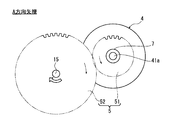
- FIG. 2 is a view in the direction of arrow A in FIG. 1 showing a first gear train of a hybrid drive system to which the shift control device of the first embodiment is applied.
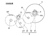
- FIG. 3 is a view in the direction of the arrow B in FIG. 1 showing a second gear train of a hybrid drive system to which the shift control device of the first embodiment is applied.
- It is the schematic which shows an example of the shift actuator which has in the hybrid drive system to which the transmission control apparatus of Example 1 was applied.
- FIG. 1 is an overall configuration diagram illustrating a drive system of a hybrid vehicle to which a transmission control device according to a first embodiment is applied.
- FIG. 2 is a view in the direction of arrow A in FIG. 1 showing a first gear train
- FIG. 3 is a control block diagram illustrating a shift control system in the shift control apparatus for a hybrid vehicle according to the first embodiment. It is a flowchart which shows the structure and flow of a shift control process at the time of the upshift performed by the integrated controller of Example 1. It is a flowchart which shows the structure and flow of a shift control process at the time of the downshift performed by the integrated controller of Example 1.
- FIG. 6 is an operation explanatory diagram illustrating a first one-way clutch engagement operation in the shift control device for a hybrid vehicle according to the first embodiment.
- FIG. 6 is an operation explanatory diagram showing a second one-way clutch fastening operation in the shift control device for a hybrid vehicle of the first embodiment.
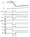
- Engine speed, transmission input shaft speed, vehicle speed, motor / generator, start clutch, first one-way clutch, second one-way clutch, throttle opening, 1 at engine start and start in the hybrid vehicle of the first embodiment It is a time chart which shows each characteristic of a high-speed dog clutch and a 2-speed dog clutch.
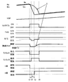
- the engine speed when the engine speed is below a predetermined value, the engine speed at the time of upshifting, the transmission input shaft speed, the vehicle speed, the engine torque down, the throttle opening, the motor / generator, the starting clutch, It is a time chart which shows each characteristic of the 1st one way clutch, the 2nd one way clutch, the 1st speed dog clutch, and the 2nd speed dog clutch.
- the engine speed at the time of upshifting the transmission input shaft speed, the vehicle speed, the engine torque down, the throttle opening, the motor / generator, the starting clutch
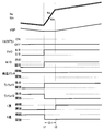
- Engine speed, transmission input shaft speed, vehicle speed, engine torque down, throttle opening, motor / generator, starting clutch, first one-way clutch, second one-way clutch, downshift in the hybrid vehicle of the first embodiment It is a time chart which shows each characteristic of a 1st speed dog clutch and a 2nd speed dog clutch.
- FIG. 1 shows a drive system of a hybrid vehicle to which the shift control device of the first embodiment is applied.
- 2 and 3 show a first gear train and a second gear train of a hybrid drive system to which the transmission control device of the first embodiment is applied.
- the overall configuration of the FF hybrid drive system will be described below with reference to FIGS.
- the drive system of the hybrid vehicle to which the shift control device of the first embodiment is applied includes an engine 1, a gear-type multi-stage transmission 2, a start clutch 3, a motor / generator 4, A gear train 5, a second gear train 6, a first one-way clutch 7, a second one-way clutch 8, a final reduction gear train 9, a differential gear 10, a left drive shaft 11, a right drive shaft 12, A left front wheel 13 (drive wheel) and a right front wheel 14 (drive wheel) are provided.
- the engine 1 is an internal combustion engine such as a gasoline engine or a diesel engine. Based on an engine control command from an engine controller 101 (described later) to an engine actuator 112, engine start control, throttle valve opening control, and fuel cut control. Etc. are performed. A flywheel 16 is provided on the crankshaft 15 of the engine 1.
- the gear-type multi-stage transmission 2 is a transmission called a single clutch type automatic MT in which the shift stage of the manual transmission is automated by a dog clutch mechanism 24 (shift stage selection clutch mechanism).
- a hydraulic-less multi-stage transmission that has five forward speeds and one reverse speed and that performs shift control by a motor actuator without using a hydraulic actuator is employed.
- the gear-type multi-stage transmission 2 is also called a parallel two-shaft multi-stage transmission, and includes a transmission input shaft 21 coaxially arranged with the crankshaft 15, a transmission output shaft 22 arranged parallel to the transmission input shaft 21, and It has.
- the transmission input shaft 21 has a first speed gear 21a, a third speed gear 21b, a second speed gear 21c, a fourth speed gear 21d, a fifth speed gear 21e, and a reverse gear 21f, and each gear 21a, 21b, 21c, 21d, 21e and 21f are provided integrally with the transmission input shaft 21 or fixed integrally with the transmission input shaft 21.
- the transmission output shaft 22 includes a first speed selection gear 22a, a third speed selection gear 22b, a second speed selection gear 22c, a fourth speed selection gear 22d, a fifth speed selection gear 22e, and a reverse selection gear 22f. Accordingly, the fixing to the transmission output shaft 22 is selected.
- the first gear to fifth gear 21a, 21b, 21c, 21d, 21e and the first gear selection gear to fifth gear selection gear 22a, 22b, 22c, 22d, 22e always have a pair of gears combined for each gear. It is in meshing state. However, the reverse gear 21f and the reverse selection gear 22f are engaged with each other via a reverse counter gear 23 for reversing the rotation direction (see FIG. 3). Each of the first to reverse gears is selected by the dog clutch mechanism 24 having no synchro capacity.
- the dog clutch mechanism 24 includes a 1-3 dog clutch mechanism 24a, a 1-3 shift fork 24b, a 2-4 dog clutch mechanism 24c, a 2-4 shift fork 24d, a 5-R dog clutch mechanism 24e, and a 5-R shift. And a fork 24f.
- the 1-3 dog clutch mechanism 24a and the 1-3 shift fork 24b are set at positions between the first speed selection gear 22a and the third speed selection gear 22b, and the transmission output of the first speed selection gear 22a or the third speed selection gear 22b.
- the fixing to the shaft 22 is selected by meshing fitting.
- the 2-4 dog clutch mechanism 24c and the 2-4 shift fork 24d are set at positions between the 2nd speed selection gear 22c and the 4th speed selection gear 22d, and the transmission output of the 2nd speed selection gear 22c or the 4th speed selection gear 22d.
- the fixing to the shaft 22 is selected by meshing fitting.
- the 5-R dog clutch mechanism 24e and the 5-R shift fork 24f are set at a position between the 5-speed selection gear 22e and the reverse selection gear 22f, and the transmission output shaft 22 of the 5-speed selection gear 22e or the reverse selection gear 22f. Is fixed by meshing engagement.
- the starting clutch 3 is a dry friction clutch that is interposed between the crankshaft 15 and the transmission input shaft 21 and connects and disconnects torque transmission between the crankshaft 15 and the transmission input shaft 21.
- the starting clutch 3 has an engagement torque capacity controlled by rotational drive control of the clutch motor 35 based on a control command from a clutch controller 103 to be described later to the clutch motor driver 115.
- the motor / generator 4 is a synchronous motor / generator having a rotor shaft 41, a rotor 42 having a permanent magnet embedded therein, and a stator 43 around which a stator coil is wound.
- the motor / generator 4 can operate as an electric motor that rotates by receiving power supplied from the battery 114 (this operation state is hereinafter referred to as “powering”), and the rotor 42 includes the engine 1 and the left and right front wheels 13. , 14 functions as a generator that generates electromotive force at both ends of the stator coil, and can also charge the battery 114 (hereinafter, this operation state is referred to as “regeneration”).
- a rotor shaft 41 extending in both axial directions from the motor / generator 4 is arranged in parallel to the crankshaft 15 and the transmission input shaft 21.
- the first gear train 5 is a gear train that drives and connects the engine-side first rotor shaft end portion 41 a of the rotor shaft 41 and the crankshaft 15 of the engine 1. As shown in FIGS. 1 and 2, the first gear train 5 is fixed to the first motor gear 51 fixed to the first rotor shaft end 41 a and the crankshaft 15 from the engine 1. And an engine crank gear 52 that meshes with the engine crank gear 52.
- the second gear train 6 extends in the crankshaft direction from the second rotor shaft end portion 41 b on the transmission input shaft side of the rotor shaft 41 and the rear end portion of the transmission input shaft 21, that is, from the engine 1.
- a gear train that connects and drives an end located on the side far from the engine 1.
- the second gear train 6 is disposed in the last train of each speed gear disposed on the transmission input shaft 21, and is reverse gear 21 f (synchronized with the transmission input shaft 21).
- a rear counter gear 23 that meshes with the reverse gear 21f, a second motor gear 61 that is fixed to the second rotor shaft end 41b, and an additional counter shaft 63 that is fixed to the second motor gear 61 and the reverse counter.
- an additional counter gear 62 that meshes with the gear 23 simultaneously.
- the first one-way clutch 7 is interposed between the first rotor shaft end portion 41a and the first motor gear 51 of the first gear train 5, and is composed of an inner race and an outer race (not shown).
- the inner race is fixed to the first rotor shaft end portion 41a, and is a clutch that is fastened by mechanical engagement only when the rotational speed of the inner race is greater than or equal to the rotational speed of the outer race (hereinafter simply referred to as “ It is described as “a clutch that is fastened by mechanical engagement only when the motor rotational speed is equal to or higher than the engine rotational speed”. Note that the first one-way clutch 7 is idled (released) when the inner race rotational speed is less than the outer race rotational speed and the mechanical engagement is released.
- the first one-way clutch 7 is engaged only when torque is transmitted from the motor / generator 4 to the engine 1. Thereby, in the torque transmission between the motor / generator 4 and the engine 1, only the torque from the motor / generator 4 side to the engine 1 side is transmitted.
- the second one-way clutch 8 is interposed between the second rotor shaft end 41b and the second motor gear 61 of the second gear train 6, and is composed of an outer race and an inner race (not shown).
- the inner race is fixed to the second rotor shaft end 41b.
- a clutch that is fastened by mechanical engagement only when the outer race rotation speed is greater than or equal to the inner race rotation speed hereinafter simply referred to as “when the transmission input shaft rotation speed is equal to or higher than the motor rotation speed).
- a clutch that is fastened by mechanical engagement only The second one-way clutch 8 is idled (released) when the mechanical engagement is released when the rotational speed of the outer race is less than the rotational speed of the inner race.
- the second one-way clutch 8 is engaged only when torque is transmitted from the gear type multi-stage transmission 2 to the motor / generator 4. Thereby, in the torque transmission between the gear type multi-stage transmission 2 and the motor / generator 4, only the torque from the gear type multi-stage transmission 2 side to the motor / generator 4 side is transmitted.
- the final reduction gear train 9 includes a transmission output gear 91 provided at an end position of the transmission output shaft 22, a drive output reduction gear 92 that meshes with the transmission output gear 91 and rotates the differential case of the differential gear 10.
- a gear train having The drive output to the differential case of the differential gear 10 is equally distributed to the left and right, transmitted to the left front wheel 13 via the left drive shaft 11, and transmitted to the right front wheel 14 via the right drive shaft 12.
- FIG. 4 shows an example of the starting clutch 3 used in the hybrid drive device of the first embodiment.
- the starting clutch 3 includes a clutch plate 31, an engine-side pressure plate 32, and a transmission-side pressure plate 34.
- the clutch plate 31 is splined to the end position of the transmission input shaft 21. And it is interposed between a fixed engine side pressure plate 32 that is spline-fitted to the crankshaft 15 and a transmission side pressure plate 34 that is movable in the axial direction. That is, among the three plates 31, 32, 34, the clutch releasing state is achieved by releasing the fastening force from the transmission-side pressure plate 34. Then, a clutch fastening state is established by applying a fastening force from the transmission-side pressure plate 34 and closing the gap to integrate the three plates 31, 32, 34.
- the motor actuator that applies the fastening force to the starting clutch 3 is an actuator that is driven without using any hydraulic pressure, and includes a motor 35, a ball screw 36, a spring 37, a roller 38, and an engagement lever 39. Configured. That is, when the ball screw 36 is moved by the motor 35, the roller 38 serving as a fulcrum of the engagement lever 39 moves in the vertical direction in FIG. By this fulcrum movement of the engagement lever 39, a fastening force based on a biasing force by the spring 37 is applied to the first pressure plate 33 and the second pressure plate. As described above, since the output from the motor 35 is not used as the fastening force, there is an advantage that the fastening force can be sufficiently applied to the starting clutch 3 even with a small motor output.
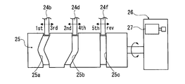
- FIG. 5 shows an example of a shift actuator used in the shift control device for a hybrid vehicle according to the first embodiment.
- the schematic configuration of the shift actuator will be described below with reference to FIG.
- the shift actuator moves the 1-3 shift fork 24b, the 2-4 shift fork 24d, and the 5-R shift fork 24f in the axial direction according to the position of the selected gear position. 26.
- the cylindrical drum 25 has a 1-3 shift cam groove 25a for guiding the axial movement of the 1-3 shift fork 24b, a 2-4 shift cam groove 25b for guiding the axial movement of the 2-4 shift fork 24d, and 5
- a 5-R shift cam groove 25c for guiding the axial movement of the -R shift fork 24f is formed along the cylindrical surface.
- the motor mechanism 26 decelerates the shift motor 27 using a DC motor and rotates the cylindrical drum 25 according to the selected gear position.
- the rotation of the cylindrical drum 25 causes the shift cam grooves 25a so that the 1-3 shift fork 24b, the 2-4 shift fork 24d, and the 5-R shift fork 24f are switched from the speed stage before selection to the speed stage after selection. , 25b, 25c along the axial direction.
- the three shift forks 24b, 24d, and 24f are driven by one motor mechanism 26, there is an advantage that the configuration of the shift actuator can be simplified.
- FIG. 6 shows a shift control system in the shift control apparatus for the hybrid vehicle of the first embodiment.
- the shift control system in the shift control apparatus for a hybrid vehicle includes an integrated controller 100, an engine controller 101, a motor controller 102, a clutch controller 103, and a shift controller 104. ing. These controllers 100, 101, 102, 103, and 104 are connected to be able to exchange information through a bidirectional communication line 105 such as a CAN communication line.
- a bidirectional communication line 105 such as a CAN communication line.
- the integrated controller 100 receives switch signals and sensor signals from an ignition key switch 106, an engine speed sensor 107, a transmission input shaft rotation sensor 108, a transmission output shaft rotation sensor 109, a throttle opening sensor 110, a vehicle speed sensor 111, and the like. input. Then, based on these input information, the dog / clutch mechanism performs the engine start control for starting the engine 1 using the motor / generator 4 as a starter motor, the start control for increasing the engagement torque capacity of the start clutch 3 in the first speed state, and the switching of the shift stage. The shift control performed by 24 is executed.
- the engine controller 101 When the engine controller 101 receives a control command from the integrated controller 100 via the bidirectional communication line 105, the engine controller 101 outputs a control signal based on the control command to the engine actuator 112.
- a control command is received from the integrated controller 100 during upshifting, engine torque down control is performed by retard or fuel cut.
- the electronic throttle is quickly opened.
- the motor controller 102 When the motor controller 102 receives a control command from the integrated controller 100 via the bidirectional communication line 105, the motor controller 102 outputs a control signal based on the control command to the inverter 113.
- the rotational speed of the motor / generator 4 When a control command is received from the integrated controller 100 during upshifting, the rotational speed of the motor / generator 4 is controlled to set the rotational speed of the engine 4 to the target engine rotational speed or the rotational speed of the transmission input shaft 21 to the target. Regenerative control (rotational speed control) is performed to match the transmission input shaft rotational speed.
- the engine torque canceling control for canceling the engine torque transmitted by the dog clutch by the power running control during coasting and the regenerative control during driving, and the motor / generator 4 Power running control (rotational speed control) is performed to match the rotational speed of the engine 4 with the target engine rotational speed by controlling the rotational speed of the engine.
- the clutch controller 103 When the clutch controller 103 receives a control command from the integrated controller 100 via the bidirectional communication line 105, the clutch controller 103 outputs a control signal based on the control command to the clutch motor driver 115.
- a control command is received from the integrated controller 100 at the time of upshifting or downshifting when the engine speed Ne is equal to or less than a predetermined value Ne1, control is performed to maintain the engagement torque capacity of the starting clutch 3.
- a control command is received from the integrated controller 100 during an upshift where the engine speed Ne exceeds a predetermined value Ne1
- clutch capacity zero control is performed, and when the dog clutch is released / engaged, clutch capacity increase control is performed.
- the shift controller 104 When the shift controller 104 receives a control command from the integrated controller 100 via the bidirectional communication line 105, the shift controller 104 outputs a control signal based on the control command to the shift motor driver 116.
- the clutch release control When a control command is received from the integrated controller 100 at the time of upshifting or downshifting, the clutch release control for releasing the dog clutch engaged at the gear stage before the gear shift and the dog clutch released at the gear stage after the gear shift are engaged. Clutch engagement control is performed.
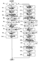
- FIG. 7 shows a configuration and a flow of a shift control process at the time of upshift executed by the integrated controller 100 of the first embodiment (shift control means).
- This upshift control process is started while giving the starting clutch 3 a fastening torque capacity in response to an upshift command issued when the operating point (TVO, VSP) on the shift map crosses the upshift line.
- step S1 it is determined whether or not the engine speed Ne is equal to or less than a predetermined value Ne1. If YES (Ne ⁇ Ne1), the process proceeds to step S2, and if NO (Ne> Ne1), the process proceeds to step S11.
- the predetermined value Ne1 is a value determined by the inertia of (engine 1 + starting clutch 3 + transmission input shaft 21) and the output value (wattage) of the motor / generator 4. Specifically, after the rotation synchronization control by the regenerative control of the motor / generator 4 is started, the engine rotation speed becomes the target engine rotation speed Ne * (n + 1) after the upshift, and the rotation synchronization control ends.
- the engine speed Ne is set so that the time required until the time becomes a desired time (for example, 0.2 sec).
- step S2 following the determination that Ne ⁇ Ne1 in step S1, engine torque down control that prompts the dog clutch engaged in n-speed to be released is started, and the process proceeds to step S3.
- step S3 following the start of engine torque reduction control in step S2, a command to release the dog clutch engaged at the nth speed is output, and the process proceeds to step S4.
- step S4 following the n-speed dog clutch release command in step S3, the motor / generator 4 under power running control is temporarily set to the neutral state, and then regeneration control by the motor / generator 4 is started, and the process proceeds to step S5. .
- the start of the regenerative control of the motor / generator 4 means the start of the rotation synchronous control in which the engine speed Ne at the start of the upshift is decreased and matched with the target engine speed Ne * (n + 1) after the upshift . To do.
- step S5 following the start of motor regeneration control in step S4, it is determined whether or not the release of the dog clutch engaged at the n-th speed has been completed. If YES (n-speed dog clutch release complete), the process proceeds to step S6. If NO (n-speed dog clutch release complete), the determination in step S5 is repeated.
- step S6 following the determination in step S5 that the n-speed dog clutch release is complete, the absolute value of the difference between the actual engine speed Ne at that time and the target engine speed Ne * (n + 1) after the upshift . Is less than the set deviation ⁇ 1. If YES (
- the set deviation ⁇ 1 is a value at which the actual engine speed Ne is substantially close to the target engine speed Ne * (n + 1), and the engagement command may be issued to the dog clutch that is engaged at the (n + 1) speed. Set to the rotation value.
- step S7 following the determination that
- step S8 following the (n + 1) -speed dog clutch engagement command in step S7, it is determined whether or not (n + 1) -speed dog clutch engagement is complete. If YES ((n + 1) -speed dog clutch engagement complete), the process proceeds to step S9. If NO ((n + 1) -speed dog clutch engagement is incomplete), the determination in step S8 is repeated.
- step S9 following the determination that the (n + 1) -speed dog clutch engagement is completed in step S8, the engine torque down control is terminated, and the process proceeds to step S10.
- step S10 following the end of the engine torque reduction control in step S9, the motor regeneration control ends, and the process proceeds to the end.
- step S11 following the determination that Ne> Ne1 in step S1, clutch capacity zero control for starting the clutch capacity of the starting clutch 3 maintaining the engagement torque capacity is started, and the process proceeds to step S12.
- This clutch capacity zero control refers to control that causes the torque transmission amount to become zero by slipping the starting clutch 3 so that the clutch 3 is slipped.
- This clutch capacity zero control prompts the dog clutch that is engaged at the n-th speed to be released.
- step S12 engine torque down control is started following the start of clutch capacity zero control in step S11, and the process proceeds to step S13.
- step S13 following the start of engine torque reduction control in step S12, a command to release the dog clutch engaged at the n-th speed is output, and the process proceeds to step S14.
- step S14 following the n-speed dog clutch release command in step S13, the motor / generator 4 under power running control is temporarily set to the neutral state, and then regeneration control by the motor / generator 4 is started, and the process proceeds to step S15.
- the start of the regenerative control of the motor / generator 4 reduces the transmission input shaft rotational speed Nin at the start of the upshift, and rotates it to match the target transmission input shaft rotational speed Nin * (n + 1) after the upshift . It means the start of synchronous control.
- step S15 following the start of the motor regeneration control in step S14, it is determined whether or not the release of the dog clutch engaged at the n-th speed is completed. If YES (n-speed dog clutch release complete), the process proceeds to step S16. If NO (n-speed dog clutch release complete), the determination in step S15 is repeated.
- step S16 following the determination that the n-speed dog clutch release is complete in step S15, the actual transmission input shaft rotational speed Nin at that time and the target transmission input shaft rotational speed Nin * (n + 1) after the upshift are performed . ) Is determined as to whether or not the absolute value of the difference is less than the set deviation ⁇ 1 ′. If YES (
- the set deviation ⁇ 1 ′ is a value at which the actual transmission input shaft rotational speed Nin is substantially close to the target transmission input shaft rotational speed Nin * (n + 1), and is engaged with the dog clutch that is engaged at the (n + 1) speed. It is set to a small rotation value at which a command can be issued.
- step S17 following the determination that
- step S18 following the (n + 1) -speed dog clutch engagement command in step S17, it is determined whether or not (n + 1) -speed dog clutch engagement is complete. If YES ((n + 1) -speed dog clutch engagement complete), the process proceeds to step S19. If NO ((n + 1) -speed dog clutch engagement is incomplete), the determination in step S18 is repeated.
- step S19 following the determination that the (n + 1) -speed dog clutch engagement is complete in step S18, the clutch capacity zero control is terminated, and the process proceeds to step S20.
- step S20 following the end of clutch capacity zero control in step S19, control is performed to increase the clutch capacity in accordance with the deviation e so as to gradually decrease the deviation e, which is the rotational speed difference (slip amount) of the starting clutch 3.
- the deviation e is calculated from the absolute value of the difference between the engine speed Ne and the transmission input shaft speed Nin.
- step S21 following the start of clutch capacity control according to the deviation e in step S20, it is determined whether or not the deviation e is less than the set deviation ⁇ 2. If YES (e ⁇ 2), the process proceeds to step S22. If NO (e ⁇ ⁇ 2), the determination in step S21 is repeated.
- the set deviation ⁇ 2 is set to a small value that does not cause a shift shock even when the start clutch 3 is shifted to the fully engaged state.
- step S22 following the determination that e ⁇ 2 in step S21, the clutch capacity control is terminated, and the process shifts to complete engagement control in which the starting clutch 3 is engaged without slipping, and the process proceeds to step S23.
- step S23 following the end of the clutch capacity control of the starting clutch 3 in step S22, the engine torque down control is ended, and the process proceeds to step S24.
- step S24 following the end of the engine torque reduction control in step S23, the motor regeneration control is ended, and the process proceeds to the end.
- FIG. 8 shows the configuration and flow of a shift control process at the time of a down shift executed by the integrated controller 100 of the first embodiment (shift control means).
- This downshift control process is started while giving the starting clutch 3 a fastening torque capacity in response to a downshift command issued when the operating point (TVO, VSP) on the shift map crosses the downshift line.
- step S31 engine torque canceling control by powering control or regenerative control of the motor / generator 4 is started, and the process proceeds to step S32.
- the engine torque canceling control refers to control that prompts the dog clutch to be released by canceling (cancelling) the engine torque transmitted by the dog clutch that is engaged at the n-th speed.
- engine torque cancellation is performed by powering control of the motor / generator 4.
- driving by depressing the accelerator engine torque cancellation is performed by regenerative control of the motor / generator 4.
- step S32 following the start of the engine torque cancel control in step S31, a release command for the dog clutch engaged at the n-th speed is output, and the process proceeds to step S33.
- step S33 following the n-speed dog clutch release command in step S32, it is determined whether or not the release of the dog clutch engaged in n-speed is completed. If YES (n-speed dog clutch release complete), the process proceeds to step S34. If NO (n-speed dog clutch release complete), the determination in step S33 is repeated.
- step S34 following the determination that the n-speed dog clutch release is completed in step S33, the engine torque canceling control is terminated, and the process proceeds to step S35.
- step S35 following the end of the engine torque cancellation control in step S34, the power running control by the motor / generator 4 is started, and the process proceeds to step S36.
- the start of the power running control of the motor / generator 4 means the start of the rotation synchronization control that increases the engine speed Ne at the start of the downshift and matches the target engine speed Ne * (n-1) after the downshift. To do.
- control for quickly opening the electronic throttle of the engine 1 is performed so that rotation synchronization is performed quickly.
- step S36 following the start of motor power running control in step S35, the absolute value of the difference between the actual engine speed Ne at that time and the target engine speed Ne * (n-1) after the downshift is less than the set deviation ⁇ . Judge whether there is. If YES (
- the set deviation ⁇ is a value at which the actual engine speed Ne is substantially close to the target engine speed Ne * (n ⁇ 1), and even if an engagement command is issued to the dog clutch that is engaged at the (n ⁇ 1) speed. Set to a good small rotation number.
- step S37 following the determination that
- step S38 following the (n-1) speed dog clutch engagement command in step S37, it is determined whether or not (n-1) speed dog clutch engagement is complete. If YES (completion of (n-1) -speed dog clutch engagement), the process proceeds to step S9. If NO ((n-1) -speed dog clutch engagement is incomplete), the determination in step S38 is repeated.
- step S39 following the determination that the (n-1) speed dog clutch engagement is complete in step S38, the motor power running control is terminated and the process proceeds to the end.
- the effects of the shift control device of the hybrid vehicle of the first embodiment are “power running control action by engaging the first one-way clutch”, “regeneration control action by engaging the second one-way clutch”, “up-shifting action in the low engine speed range”, The explanation will be divided into “upshifting action in the high engine speed range” and “downshifting action”.
- the first one-way clutch 7 is interposed at one end of the rotor shaft 41 of the motor / generator 4 and the second one-way clutch 8 is interposed at the other end.
- the power running control action by the engagement of the first one-way clutch 7 will be described.
- Power assist power running control action For example, at the time of starting or during intermediate acceleration, it is necessary to assist the driving force of the engine 1 with the driving force of the motor / generator 4 (power assist).
- power assist power running control is performed in which the motor / generator 4 is subjected to power running control (torque control) while the start clutch 3 is engaged.
- the power running energy from the rotor shaft 41 of the motor / generator 4 by this power running control is transmitted from the first one-way clutch 7 ⁇ the first motor gear 51 ⁇ the engine crank gear 52 ⁇ the crankshaft 15 to the driving force from the engine 1, Driving force from the motor / generator 4 is applied.
- the combined driving force passes through the starting clutch 3 and is transmitted to the transmission input shaft 21.
- FIG. 11 is a time chart showing characteristics at the time of engine start and start in the hybrid vehicle of the first embodiment. Hereinafter, the engine start / start control action will be described with reference to FIG. To do.
- the first one-way clutch 7 is interposed at one end of the rotor shaft 41 of the motor / generator 4 and the second one-way clutch 8 is interposed at the other end.
- the regeneration control action by the engagement of the second one-way clutch 8 will be described.
- Engine energy regenerative control action For example, when the battery charge capacity decreases during traveling, the battery 114 needs to be charged using a part of the engine energy.
- engine energy regeneration control for performing regeneration control (torque control) of the motor / generator 4 with the start clutch 3 engaged is executed. Therefore, a part of the energy from the crankshaft 15 of the engine 1 is generated by the starting clutch 3 ⁇ the transmission input shaft 21 ⁇ the reverse gear 21f ⁇ the reverse counter gear 23 ⁇ the additional counter gear 62 ⁇ the second motor gear 61 ⁇ the second one-way clutch 8 ⁇ Transmitted to the rotor shaft 41.
- the motor / generator 4 captures a part of the engine energy as regenerative energy, and charges the electric power obtained by the power generation by the motor / generator 4 as the charging power for the battery 114. That is, the motor / generator 4 exhibits an engine energy regeneration function that takes in part of the engine energy as regenerative energy, and the battery 114 can be charged as necessary during traveling.
- coast energy regenerative control action For example, when decelerating by an accelerator release operation, or when decelerating and stopping, regenerating coast energy to give regenerative braking force to driving wheels leads to improved fuel efficiency.
- coasting energy regeneration control is performed in which the starting clutch 3 is released and the motor / generator 4 is subjected to regeneration control (torque control). Therefore, the coast energy from the left and right front wheels 13 and 14 is changed from the drive shafts 11 and 12 to the differential gear 10 ⁇ the final reduction gear train 9 ⁇ the transmission output shaft 22 ⁇ the meshing gear at the selected stage ⁇ the transmission input shaft 21 ⁇ the reverse gear.
- the motor / generator 4 takes in coast energy from the left and right front wheels 13 and 14 by coast running as regenerative energy, and charges the electric power obtained by the power generation by the motor / generator 4 as charging power to the battery 114. That is, the motor / generator 4 exhibits a coast energy regeneration function that takes in coast energy from the left and right front wheels 13 and 14 by coast traveling as regeneration energy, and the battery 114 can be charged during coast traveling.
- step S5 When it is determined in step S5 that the dog clutch that has been engaged at the n-th speed has been released, the process proceeds from step S5 to the next step S6.
- step S6 it is determined whether or not the absolute value of the difference between the actual engine speed Ne and the target engine speed Ne * (n + 1) after the upshift is less than the set deviation ⁇ 1. That is, the completion of rotation synchronization is determined when the actual engine speed Ne is reduced to a value close to the target engine speed Ne * (n + 1) by the regeneration control of the motor / generator 4. If it is determined in step S6 that the rotation synchronization during the upshift is completed, the process proceeds from step S6 to step S7 to step S8. In step S7, a clutch engagement command is issued to the released (n + 1) speed dog clutch. In step S8, it is determined whether or not the engagement of the (n + 1) speed dog clutch is completed.
- step S8 When it is determined in step S8 that the (n + 1) -speed dog clutch is completely engaged, the process proceeds from step S8 to step S9 ⁇ step S10 ⁇ end.
- step S9 the engine torque reduction control is terminated, and in step S10, the motor regeneration control is terminated.
- the upshift control process in the low engine speed range is performed according to the above processing flow.
- the rotation synchronous control by the regenerative control of the motor / generator 4 is performed by the cooperation of the motor / generator 4 and the engine 1 which are in a drive-coupled state when the start clutch 3 is engaged, so that the time required to reach the synchronous rotational speed is shortened. Is done. That is, the brake torque due to the power generation load acts on the rotor shaft 41 by the regeneration control of the motor / generator 4. The brake torque of the rotor shaft 41 is transmitted to the second one-way clutch 8 ⁇ the second motor gear 61 ⁇ the additional counter gear 62 ⁇ the reverse counter gear 23 ⁇ the reverse gear 21 f ⁇ the transmission input shaft 21 ⁇ the starting clutch 3 ⁇ the crankshaft 15. Is done.
- the upshift control in the low engine speed range is performed by quickly releasing the clutch and quickly engaging the clutch while providing the starting clutch 3 with the engagement torque capacity. For this reason, at the time of upshifting in the low engine speed range, only a short time from the release of the n-speed dog clutch to the engagement of the (n + 1) -speed dog clutch results in the torque being cut off, and the feeling of idling due to the torque cut is suppressed to a small level.
- the upshifting action in the engine low speed range will be described with reference to the time chart of FIG.
- the torque reduction control of the engine 1 is started at time t1 and the power running control of the motor / generator 4 is released, the first one-way clutch 7 is released, and the first-speed dog clutch engaged at the first speed is released.
- the second one-way clutch 8 is engaged, and the actual engine speed Ne is set to the second target engine speed between time t2 and time t3.
- Rotation synchronous control is performed to pull down toward the number Ne * (n + 1).
- step S11 clutch capacity zero control for starting the clutch capacity of the starting clutch 3 is started, and in step S12, engine torque down control is started.
- step S13 a release command for the dog clutch engaged at the n-th speed is output, and in step S14, regeneration control is started after a temporary neutral state has elapsed.
- step S15 it is determined whether or not the release of the dog clutch engaged at the n-th speed is completed.
- step S15 it is determined whether or not the absolute value of the difference between the actual transmission input shaft rotational speed Nin and the target transmission input shaft rotational speed Nin * (n + 1) after the upshift is less than the set deviation ⁇ 1 ′. Is done. That is, the completion of rotation synchronization is determined when the actual transmission input shaft rotational speed Nin decreases to a value close to the target transmission input shaft rotational speed Nin * (n + 1) by the regeneration control of the motor / generator 4.
- step S16 If it is determined in step S16 that the rotation synchronization during the upshift is completed, the process proceeds from step S16 to step S17 to step S18.
- step S17 a clutch engagement command is issued to the opened (n + 1) speed dog clutch.
- step S18 it is determined whether or not the engagement of the (n + 1) -speed dog clutch is completed.
- step S18 When it is determined in step S18 that the (n + 1) -speed dog clutch is completely engaged, the process proceeds from step S18 to step S19 ⁇ step S20 ⁇ step S21.
- step S19 the clutch capacity zero control is terminated, and in step S20, control is performed to increase the clutch capacity in accordance with the deviation e so as to gradually reduce the deviation e, which is the rotational speed difference (slip amount) of the starting clutch 3.
- step S21 it is determined whether or not the deviation e is less than the set deviation ⁇ 2.
- step S21 When it is determined in step S21 that the deviation e is less than the set deviation ⁇ 2, the process proceeds from step S21 to step S22 ⁇ step S23 ⁇ step S24 ⁇ end.
- step S22 the clutch capacity control is finished, and the starting clutch 3 is brought into a completely engaged state without slipping.
- step S23 the engine torque down control is finished, and in step S24, the motor regeneration control is finished.
- the upshift control process in the high engine speed range is performed according to the above processing flow.
- the rotation synchronization control by the regenerative control of the motor / generator 4 is instantaneously performed between the motor / generator 4 and the transmission input shaft 21 which are in a drive-connected state by opening the start clutch 3. That is, the brake torque due to the power generation load acts on the rotor shaft 41 by the regeneration control of the motor / generator 4.
- the brake torque of the rotor shaft 41 is transmitted from the second one-way clutch 8 ⁇ the second motor gear 61 ⁇ the additional counter gear 62 ⁇ the reverse counter gear 23 ⁇ the reverse gear 21f ⁇ the transmission input shaft 21.
- the brake torque from the rotor shaft 41 of the motor / generator 4 changes the rotational speed of the transmission input shaft 21 (actual transmission input shaft rotational speed Nin) to the target transmission input shaft rotational speed Nin * (n + after the upshift .
- Rotational synchronization control is performed to instantaneously pull down to a value close to 1).
- the clutch capacity control that gives the clutch capacity from the zero capacity control of the start clutch 3 is performed by gradually increasing the clutch capacity while monitoring the deviation e which is the slip amount of the start clutch 3. For this reason, after the (n + 1) -speed dog clutch is engaged, the driving force transmitted to the driving wheels is gradually recovered while suppressing the decreasing gradient of the engine speed Ne.
- the upshift control in the high engine speed range is performed by the clutch capacity zero control of the start clutch 3, the quick clutch release and quick clutch engagement of the dog clutch mechanism, and the clutch capacity increase control of the start clutch 3. .
- the predetermined value Ne1 of the engine speed Ne is an engine speed Ne at which a time required from the start of the rotation synchronization control by the regeneration control of the motor / generator 4 to the end of the rotation synchronization control becomes a desired time (for example, 0.2 sec). Is set. For example, in the high engine speed range where the engine speed Ne exceeds a predetermined value Ne1, if the up-shift control of the engine low speed range is performed, rotation synchronization is required to reduce the high engine speed to the synchronous speed. The time becomes longer, and the feeling of free running due to running out of torque appears.
- the upshift control in the high engine speed range is the rotation synchronization control with the zero displacement control of the starting clutch 3, thereby eliminating the influence of engine inertia that lengthens the time required for rotation synchronization. For this reason, the idling feeling due to running out of torque can be suppressed to a small level while performing the upshift control in the high engine speed range.
- step S31 engine torque cancellation control by powering control or regenerative control of the motor / generator 4 is started.
- step S32 a release command for the dog clutch engaged at the nth speed is output, and in step S33, it is determined whether or not the release of the dog clutch engaged at the nth speed is completed.
- step S33 When it is determined in step S33 that the dog clutch engaged at the n-th speed has been released, the process proceeds from step S33 to step S34 ⁇ step S35 ⁇ step S36.
- step S34 the engine torque canceling control is terminated, and in step S35, the power running control by the motor / generator 4 is started.
- step S36 it is determined whether or not the absolute value of the difference between the actual engine speed Ne at that time and the target engine speed Ne * (n-1) after the downshift is less than the set deviation ⁇ . That is, the completion of rotation synchronization is determined when the actual engine speed Ne increases to a value close to the target engine speed Ne * (n ⁇ 1) by the power running control of the motor / generator 4.
- step S36 If it is determined in step S36 that the rotation synchronization during the downshift has been completed, the process proceeds from step S36 to step S37 to step S38.
- step S37 a clutch engagement command is issued to the opened (n-1) speed dog clutch.
- step S38 it is determined whether or not the (n-1) -speed dog clutch is completely engaged.
- step S38 When it is determined in step S38 that the (n ⁇ 1) -speed dog clutch is completely engaged, the process proceeds from step S38 to step S39, where the motor power running control is terminated.
- the downshift control process is performed according to the above processing operation flow.
- the above-mentioned release control of the dog clutch engaged at the n-th speed starts the engine torque canceling control when the downshift is started.
- the motor / generator 4 is performing regenerative control at the start of downshifting
- switching to power running control is engine torque cancellation control. Therefore, the torque in the meshing release direction due to the engine torque cancellation cancels the torque acting in the meshing direction of the dog clutch, and the dog clutch engagement is quickly released.
- the rotation synchronization control by the power running control of the motor / generator 4 is performed in cooperation with the engine 1 that is in a drive-coupled state by the engagement of the start clutch 3, so that the time required to reach the synchronous rotation speed is shortened. That is, the driving torque by the motor driving acts on the rotor shaft 41 by the power running control of the motor / generator 4.
- the driving torque of the rotor shaft 41 is transmitted from the first one-way clutch 7 ⁇ the first motor gear 51 ⁇ the engine crank gear 52 ⁇ the crankshaft 15.
- the downshift control is performed by quickly releasing the clutch and quickly engaging the dog clutch mechanism while providing the starting clutch 3 with the engagement torque capacity. For this reason, at the time of downshift, only a short time from the release of the n-th dog clutch to the engagement of the (n-1) -th dog clutch causes the torque to run out.
- the downshift operation will be described with reference to the time chart of FIG.
- the throttle opening TVO is opened to the full open range by the accelerator depression operation
- the power running control of the motor / generator 4 is started, the second one-way clutch 8 is released, and the first one-way clutch 7 is engaged.
- the second-speed dog clutch that is engaged at the second speed is released.
- the throttle opening TVO is opened to the fully open range by the accelerator depressing operation at time t1
- the actual engine speed between time t1 and time t2 is achieved by the power running control of the motor / generator 4 and the quick opening of the electronic throttle.
- Rotation synchronous control is performed to raise Ne toward the first engine speed Ne * (n-1).
- Engine 1 and A motor / generator 4 A gear type multi-stage transmission 2 in which the shift of gears is automated by a gear selection clutch mechanism (dog clutch mechanism 24); A starting clutch 3 for connecting and disconnecting torque transmission from the engine 1 to the driving wheels (the left and right front wheels 13, 14); Shift control means (FIGS. 7 and 8) for controlling the shift stage of the gear type multi-stage transmission 2;
- a shift control device for a hybrid vehicle comprising: The motor / generator 4 is capable of power running and regeneration with respect to a driving force transmission system from the crankshaft 15 of the engine 1 to the transmission input shaft 21 of the gear type multi-stage transmission 2 via the starting clutch 3. age, The shift control means (FIGS.
- the gear type multi-stage transmission 2 uses a dog clutch mechanism 24 as a gear selection clutch mechanism for switching gears.
- the shift control means (FIG. 7) performs a first up shift control in response to an up shift command for switching the shift stage to the high speed stage (steps S2 to S10).
- the rotation speed Ne of the engine 1 is increased by the regeneration control of the motor / generator 4 while the starting clutch 3 has a fastening torque capacity, and the target engine speed Ne * ( n + 1) is performed, and after the clutch release control of the dog clutch mechanism 24 is completed, when the engine rotation synchronization state is confirmed, the clutch engagement control of the dog clutch mechanism 24 is performed.
- the shift control means (FIG. 7) performs the second upshift control in response to the upshift command when the rotational speed of the engine 1 when the upshift command exceeds the predetermined value N1.
- the second upshift control includes a zero control that makes the engagement torque capacity of the start clutch 3 zero, and a regenerative control of the motor / generator 4 to reduce the rotational speed Nin of the transmission input shaft 21 to the target after the upshift.
- the shift control means rotates after the engine rotation synchronization control is started and the rotation speed Ne of the engine 1 becomes the target engine rotation speed Ne * (n + 1) after the upshift.
- the engine speed Ne at which the time required until the end of the synchronization control is a desired time is set as a predetermined value Ne1, and the engine speed Ne when the upshift command is issued is equal to or less than the predetermined value Ne1. (YES in step S1), the first upshift control is executed (steps S2 to S10).
- the gear-type multi-stage transmission 2 uses a dog clutch mechanism 24 as a gear selection clutch mechanism for switching gears.
- the shift control means (FIG. 8), in response to a downshift command for switching the shift speed to the low speed position, gives the starting clutch 3 a fastening torque capacity and reverses the direction of the torque that rotates the dog clutch mechanism 24.
- Engine torque canceling control for applying the torque of the dog clutch mechanism 24 by the motor / generator 4 is started. After completion, engine rotation synchronization control is started by setting the rotation speed Ne of the engine 1 to the target engine rotation speed Ne * (n-1) after downshifting by the power running control of the motor / generator 4.
- the motor / generator 4 has a rotor shaft 41 extending in both axial directions in a parallel arrangement parallel to the crankshaft 15 and the transmission input shaft 21.
- the two gear trains 6 and the second one-way clutch 8 that is engaged when torque is transmitted from the transmission input shaft 21 to the motor / generator 4 are connected in a connectable manner.
- the motor / generator 4 the first gear train 5 and the second gear train 6 can be added to the engine 1 without increasing costs or increasing space. It is possible to set the motor / generator 4 capable of powering and regenerating the driving force transmission system that reaches the transmission input shaft 21.
- the starting clutch 3 is provided between the crankshaft 15 of the engine 1 and the transmission input shaft 21,
- the first gear train 5 is A first motor gear 51 disposed at the first rotor shaft end 41a;
- An engine crank gear 52 that is disposed on the crankshaft 15 and meshes with the first motor gear 51
- the second gear train 6 is A second motor gear 61 disposed at the second rotor shaft end 41b;
- the rear end is disposed at a position farthest from the engine 1 and meshes with the second motor gear 61.
- a gear (reverse gear 21f) is provided.
- the motor / generator 4 can have an elongated configuration corresponding to the axial length of the gear-type multi-stage transmission 2, and as a result, when the engine is driven without increasing the space.
- the motor inertia which becomes a load can be suppressed small.
- the gear-type multi-stage transmission 2 has a transmission output shaft 22 that receives torque from the transmission input shaft 21 and shifts and transmits the torque to drive wheels.
- the first gear train 5 is An engine crank gear 52 disposed on the crankshaft 15; A first motor gear 51 disposed at the first rotor shaft end 41a and meshing with the engine crank gear 52;
- the second gear train 6 is A reverse gear 21f disposed on the transmission input shaft 21 and rotating synchronously with the transmission input shaft 21; A reverse counter gear 23 that meshes with the reverse gear 21f and transmits a torque input to the transmission input shaft 21 to the transmission output shaft 22 by changing a rotation direction;
- An additional counter gear 62 meshing with the reverse counter gear 23;
- the second motor gear 61 is arranged at the second rotor shaft end portion 41 b and meshes with the additional counter gear 62.
- the power / running of the motor / generator 4 can be achieved by adding only one additional counter gear 62 by using the reverse gear 21f and the reverse counter gear 23 as a part of the second gear train 6. And the rotation direction of regeneration can be matched.
- the reverse gear 21f is a rear end disposed at a position farthest from the engine 1 among the plurality of gears 21a, 21b, 21c, 21d, 21e, and 21f disposed on the transmission input shaft 21. It is a gear. Therefore, in addition to the effect of (8), the reverse gear 21f and the reverse counter gear 23 are used as a part of the second gear train 6, and the motor / generator 4 is arranged along the axial direction of the gear type multi-stage transmission 2. By adopting the arrangement, it is possible to configure the hybrid drive device while minimizing the number of parts and space increase from the existing engine 1 + gear type multi-stage transmission 2.
- an example of a multi-stage transmission having five forward speeds and one reverse speed is shown as the gear type multi-stage transmission 2.
- the gear-type multi-stage transmission is capable of switching between a plurality of shift speeds, the specific shift speed is not limited to the fifth forward speed / first reverse speed of the first embodiment.
- the motor / generator 4 is set without causing an increase in cost or space.
- the motor / generator is set to enable power running and regeneration with respect to the driving force transmission system from the engine crankshaft through the starting clutch to the transmission input shaft of the gear type multi-stage transmission. Not limited to settings.
- gear selection operation actuator of the gear type multi-stage transmission 2 an example in which a motor actuator suitable for reducing hydraulic pressure is used as the gear selection operation actuator of the gear type multi-stage transmission 2 is shown.
- another actuator such as an electromagnetic actuator or a hydraulic actuator may be used as the gear selection actuator.
- the start clutch type may be a dry type or a wet type, and may be a single plate type or a multi-plate type.
- the first one-way clutch 7 is used as the first clutch
- the second one-way clutch 8 is used as the second clutch.
- an electromagnetic clutch, a hydraulic clutch, or the like that is connected / disconnected by an external command may be used.
- Example 1 shows an example in which the reverse gear 21f is used as the rear end gear.
- a gear other than the reverse gear may be used as long as the gear rotates in synchronization with the transmission input shaft even if it is not arranged in the last row of the transmission input shaft of the gear type multi-stage transmission.
- Embodiment 1 shows an example in which the shift control device for a hybrid vehicle of the present invention is applied to a drive system of an FF hybrid vehicle.
- the shift control device for a hybrid vehicle of the present invention can be applied to a drive system of an FR hybrid vehicle, a drive system of a 4WD hybrid vehicle, and the like.
Abstract
In a shift control apparatus for a hybrid vehicle according to the present invention, a shift control means performs, in response to a shifting command and while a starting clutch (3) is provided with engaging torque capacity: a clutch disengaging control for a dog clutch mechanism (24); an engine rotation synchronization control by regenerative control or powering control of a motor/generator (4); and a clutch engaging control for the dog clutch mechanism (24) so as to select a post-shift shift level in an engine rotation synchronized state where the rotational speed (Ne) of the engine (1) is at a post-shift target engine rotational speed.
Description
本発明は、エンジンとモータ/ジェネレータと歯車式多段変速機とを組み合わせた駆動系を備えたハイブリッド車両の変速制御装置に関する。
The present invention relates to a shift control device for a hybrid vehicle including a drive system in which an engine, a motor / generator, and a geared multi-stage transmission are combined.
従来、手動変速機の変速動作を自動化した自動MTに、遊星歯車と2つのモータ/ジェネレータを配置し、各変速段の間を無段変速することにより、エンジン出力を用いて、変速時のトルク中断を埋合わせることを可能とするハイブリッド車両の変速制御装置が知られている(例えば、特許文献1参照)。
Conventionally, a planetary gear and two motors / generators are arranged in an automatic MT that automates the shifting operation of a manual transmission, and the torque at the time of shifting is determined by using the engine output by continuously shifting between the respective shifting stages. 2. Description of the Related Art A shift control device for a hybrid vehicle that can compensate for an interruption is known (see, for example, Patent Document 1).
この特許文献1の図1に記載されたハイブリッド車両は、遊星歯車のサンギヤにモータ/ジェネレータを直結し、リングギヤを自動MTの2速ギヤに連結し、キャリアを出力軸に伝達できる構成としている。そして、同文献の図4に記載された変速制御のタイムチャートに示すように、発進クラッチを締結したままでアップ変速ができるようにしている。
The hybrid vehicle described in FIG. 1 of Patent Document 1 has a configuration in which a motor / generator is directly connected to the sun gear of the planetary gear, the ring gear is connected to the second gear of the automatic MT, and the carrier can be transmitted to the output shaft. Then, as shown in the time chart of the shift control described in FIG. 4 of the same document, the upshift can be performed while the start clutch is kept engaged.
しかしながら、従来のハイブリッド車両の変速制御装置にあっては、アップ変速時のトルクフェーズにおいて、駆動力不足となるため、それを補う別のモータ/ジェネレータが必要となり、ハイブリッドシステムが大型化する、という問題があった。さらに、遊星歯車を介して自動MTの変速機入力軸と連結するモータ/ジェネレータは、リングギヤおよびキャリアがそれぞれ変速機入力軸に設けられるギヤと連結する構造であるため、軸方向に大きなスペースが必要で、搭載面で不利になる、という問題があった。
However, in the conventional shift control device for a hybrid vehicle, since the driving force is insufficient in the torque phase at the time of upshifting, another motor / generator is required to make up for it, and the hybrid system is enlarged. There was a problem. Furthermore, the motor / generator connected to the transmission input shaft of the automatic MT via the planetary gear has a structure in which the ring gear and the carrier are respectively connected to the gear provided on the transmission input shaft, so that a large space is required in the axial direction. There was a problem that it was disadvantageous in terms of mounting.
本発明は、上記問題に着目してなされたもので、システム大型化を抑えて搭載面で有利としながら、変速時にトルク切れによる空走感を抑えることができるハイブリッド車両の変速制御装置を提供することを目的とする。
The present invention has been made paying attention to the above problems, and provides a shift control device for a hybrid vehicle capable of suppressing the feeling of idling due to running out of torque during a shift while suppressing an increase in system size and being advantageous in terms of mounting. For the purpose.
上記目的を達成するため、本発明では、前提構成として、エンジンと、モータ/ジェネレータと、変速段の切り替えを変速段選択クラッチ機構により自動化した歯車式多段変速機と、前記エンジンから駆動輪へのトルク伝達を断接する発進クラッチと、前記歯車式多段変速機の変速段の切り替え制御を行う変速制御手段と、を備えた。
このハイブリッド車両の変速制御装置において、
前記モータ/ジェネレータは、前記エンジンのクランク軸から前記発進クラッチを介し前記歯車式多段変速機の変速機入力軸に至る駆動力伝達系に対して力行と回生が可能な設定とした。
前記変速制御手段は、変速段を切り替える変速指令に対し、前記発進クラッチに締結トルク容量を持たせつつ、変速前の変速段選択を解除する前記変速段選択クラッチ機構のクラッチ開放制御と、前記モータ/ジェネレータの回生制御または力行制御により前記エンジンの回転数を変速後の目標エンジン回転数とするエンジン回転同期制御と、前記エンジンの回転数が前記変速後の目標エンジン回転数となったエンジン回転同期状態で変速後の変速段を選択する前記変速段選択クラッチ機構のクラッチ締結制御を行う。 In order to achieve the above object, in the present invention, as a precondition, an engine, a motor / generator, a gear-type multi-speed transmission in which shift speed switching is automated by a shift speed selection clutch mechanism, and the engine to drive wheels A starting clutch for connecting and disconnecting torque transmission, and a shift control means for controlling the shift of the gear-type multi-stage transmission.
In this hybrid vehicle shift control device,
The motor / generator is set to be capable of power running and regeneration with respect to a driving force transmission system from the crankshaft of the engine through the starting clutch to the transmission input shaft of the gear type multi-stage transmission.
The shift control means includes a clutch release control of the shift stage selection clutch mechanism for releasing the shift stage selection before the shift while giving the start clutch a fastening torque capacity in response to a shift command for switching the shift stage, and the motor / Engine rotation synchronization control in which the engine speed is changed to the target engine speed after the shift by regenerative control or power running control of the generator, and engine rotation synchronization in which the engine speed becomes the target engine speed after the shift In this state, the clutch engagement control of the gear selection clutch mechanism for selecting the gear after the shift is performed.
よって、モータ/ジェネレータは、エンジンのクランク軸から発進クラッチを介し歯車式多段変速機の変速機入力軸に至る駆動力伝達系に対して力行と回生が可能な設定とされる。このため、1つのモータ/ジェネレータの配置により力行と回生が可能であり、2つのモータ/ジェネレータを配置する必要があるハイブリッド駆動系に比べてシステム小型化が図られる。また、遊星歯車を用いるハイブリッド駆動系のように、軸方向に大きなスペースが必要ではなく、搭載面で有利である。
変速段を切り替えるアップ変速やダウン変速の指令に対する変速制御は、発進クラッチに締結トルク容量を持たせつつ、変速前の変速段選択を解除するクラッチ開放制御と、モータ/ジェネレータの回生制御または力行制御によりエンジン回転数を変速後の目標エンジン回転数とする回転同期制御と、エンジンの回転数が変速後の目標エンジン回転数となった回転同期状態で変速後の変速段を選択するクラッチ締結制御が行われる。
クラッチ開放制御は、例えば、変速段選択クラッチ機構がドグクラッチ機構である場合、変速開始時、エンジントルクまたは発進クラッチ容量を下げるだけで、ドグクラッチ締結が速やかに開放される。回転同期制御は、発進クラッチの締結により駆動連結状態となっているモータ/ジェネレータとエンジンの協調により行われるため、エンジンが同期回転数に達するまでの所要時間が短縮される。クラッチ締結制御は、エンジンの回転数が変速後の目標エンジン回転数となった回転同期状態になると速やかにクラッチ締結される。このように、変速制御が、発進クラッチに締結トルク容量を持たせつつ、変速段選択クラッチ機構の速やかなクラッチ開放と速やかなクラッチ締結により行われるため、変速時にトルク切れによる空走感が抑えられる。
この結果、システム大型化を抑えて搭載面で有利としながら、変速時のトルク切れによる空走感を抑えることができる。 Therefore, the motor / generator is set to be capable of power running and regeneration with respect to the driving force transmission system from the crankshaft of the engine through the starting clutch to the transmission input shaft of the gear type multi-stage transmission. For this reason, power running and regeneration are possible by the arrangement of one motor / generator, and the system can be reduced in size as compared with a hybrid drive system in which two motors / generators need to be arranged. Further, unlike a hybrid drive system using planetary gears, a large space is not required in the axial direction, which is advantageous in terms of mounting.
Shift control in response to up-shift and down-shift commands to switch the gear stage includes clutch release control that releases the gear stage selection prior to gear shift and motor / generator regenerative control or power running control while giving the starting clutch the engagement torque capacity. Rotation synchronization control for setting the engine speed to the target engine speed after the shift, and clutch engagement control for selecting the gear stage after the shift in the rotation synchronization state where the engine speed becomes the target engine speed after the shift. Done.
In the clutch release control, for example, when the shift speed selection clutch mechanism is a dog clutch mechanism, the dog clutch engagement is quickly released only by reducing the engine torque or the starting clutch capacity at the start of the shift. Since the rotation synchronization control is performed by the cooperation of the motor / generator and the engine that are in the drive-coupled state when the start clutch is engaged, the time required until the engine reaches the synchronous rotation speed is shortened. In the clutch engagement control, the clutch is quickly engaged when the rotational speed of the engine becomes the rotation synchronous state in which the target engine speed after the shift is reached. As described above, the shift control is performed by quickly releasing the clutch and rapidly engaging the clutch while the shift speed selection clutch mechanism has the engagement torque capacity of the starting clutch, so that it is possible to suppress a feeling of idling due to torque loss during a shift. .
As a result, it is possible to suppress the feeling of idling due to torque loss at the time of shifting while suppressing an increase in the size of the system, which is advantageous in terms of mounting.
以下、本発明のハイブリッド車両の変速制御装置を実現する最良の形態を、図面に示す実施例1に基づいて説明する。
Hereinafter, the best mode for realizing a shift control device for a hybrid vehicle of the present invention will be described based on Example 1 shown in the drawings.
まず、構成を説明する。
図1は、実施例1の変速制御装置が適用されたハイブリッド車両の駆動系を示す。図2および図3は、実施例1の変速制御装置が適用されたハイブリッド駆動系の第1ギヤ列と第2ギヤ列を示す。以下、図1~図3に基づきFFハイブリッド駆動系の全体構成を説明する。 First, the configuration will be described.
FIG. 1 shows a drive system of a hybrid vehicle to which the shift control device of the first embodiment is applied. 2 and 3 show a first gear train and a second gear train of a hybrid drive system to which the transmission control device of the first embodiment is applied. The overall configuration of the FF hybrid drive system will be described below with reference to FIGS.
実施例1の変速制御装置が適用されたハイブリッド車両の駆動系は、図1に示すように、エンジン1と、歯車式多段変速機2と、発進クラッチ3と、モータ/ジェネレータ4と、第1ギヤ列5と、第2ギヤ列6と、第1ワンウェイクラッチ7と、第2ワンウェイクラッチ8と、終減速ギヤ列9と、ディファレンシャルギヤ10と、左ドライブシャフト11と、右ドライブシャフト12と、左前輪13(駆動輪)と、右前輪14(駆動輪)と、を備えている。
As shown in FIG. 1, the drive system of the hybrid vehicle to which the shift control device of the first embodiment is applied includes an engine 1, a gear-type multi-stage transmission 2, a start clutch 3, a motor / generator 4, A gear train 5, a second gear train 6, a first one-way clutch 7, a second one-way clutch 8, a final reduction gear train 9, a differential gear 10, a left drive shaft 11, a right drive shaft 12, A left front wheel 13 (drive wheel) and a right front wheel 14 (drive wheel) are provided.
前記エンジン1は、ガソリンエンジンやディーゼルエンジン等の内燃機関であり、後述するエンジンコントローラ101からエンジンアクチュエータ112へのエンジン制御指令に基づいて、エンジン始動制御やスロットルバルブのバルブ開度制御、フューエルカット制御等が行われる。なお、エンジン1のクランク軸15には、フライホイール16が設けられている。
The engine 1 is an internal combustion engine such as a gasoline engine or a diesel engine. Based on an engine control command from an engine controller 101 (described later) to an engine actuator 112, engine start control, throttle valve opening control, and fuel cut control. Etc. are performed. A flywheel 16 is provided on the crankshaft 15 of the engine 1.
前記歯車式多段変速機2は、手動変速機の変速段の切り替えをドグクラッチ機構24(変速段選択クラッチ機構)により自動化したシングルクラッチ式自動MTと呼ばれる変速機である。実施例1においては、前進5速/後退1速の変速段を持ち、油圧アクチュエータを用いることなくモータアクチュエータにより変速制御を行う油圧レス多段変速機を採用している。この歯車式多段変速機2は、平行2軸式多段変速機とも呼ばれ、クランク軸15と同軸配置の変速機入力軸21と、変速機入力軸21に平行配置の変速機出力軸22と、を備えている。
The gear-type multi-stage transmission 2 is a transmission called a single clutch type automatic MT in which the shift stage of the manual transmission is automated by a dog clutch mechanism 24 (shift stage selection clutch mechanism). In the first embodiment, a hydraulic-less multi-stage transmission that has five forward speeds and one reverse speed and that performs shift control by a motor actuator without using a hydraulic actuator is employed. The gear-type multi-stage transmission 2 is also called a parallel two-shaft multi-stage transmission, and includes a transmission input shaft 21 coaxially arranged with the crankshaft 15, a transmission output shaft 22 arranged parallel to the transmission input shaft 21, and It has.
前記変速機入力軸21は、1速ギヤ21aと3速ギヤ21bと2速ギヤ21cと4速ギヤ21dと5速ギヤ21eとリバースギヤ21fを有し、各ギヤ21a,21b,21c,21d,21e,21fは、変速機入力軸21に対し一体に、あるいは、変速機入力軸21に対し一体的に固定して設けられる。
The transmission input shaft 21 has a first speed gear 21a, a third speed gear 21b, a second speed gear 21c, a fourth speed gear 21d, a fifth speed gear 21e, and a reverse gear 21f, and each gear 21a, 21b, 21c, 21d, 21e and 21f are provided integrally with the transmission input shaft 21 or fixed integrally with the transmission input shaft 21.
前記変速機出力軸22は、1速選択ギヤ22aと3速選択ギヤ22bと2速選択ギヤ22cと4速選択ギヤ22dと5速選択ギヤ22eとリバース選択ギヤ22fを有し、変速段の切り替えに応じて変速機出力軸22への固定が選択される。
The transmission output shaft 22 includes a first speed selection gear 22a, a third speed selection gear 22b, a second speed selection gear 22c, a fourth speed selection gear 22d, a fifth speed selection gear 22e, and a reverse selection gear 22f. Accordingly, the fixing to the transmission output shaft 22 is selected.
前記1速ギヤ~5速ギヤ21a,21b,21c,21d,21eと、1速選択ギヤ~5速選択ギヤ22a,22b,22c,22d,22eは、変速段毎に組み合わせた一対のギヤを常時噛み合い状態としている。但し、リバースギヤ21fとリバース選択ギヤ22fについては、回転方向を逆にするためのリバースカウンターギヤ23を介して噛み合っている(図3参照)。そして、これら1速~リバースの各変速段は、シンクロ容量のないドグクラッチ機構24により選択される。
The first gear to fifth gear 21a, 21b, 21c, 21d, 21e and the first gear selection gear to fifth gear selection gear 22a, 22b, 22c, 22d, 22e always have a pair of gears combined for each gear. It is in meshing state. However, the reverse gear 21f and the reverse selection gear 22f are engaged with each other via a reverse counter gear 23 for reversing the rotation direction (see FIG. 3). Each of the first to reverse gears is selected by the dog clutch mechanism 24 having no synchro capacity.
前記ドグクラッチ機構24は、1-3ドグクラッチ機構24aと、1-3シフトフォーク24bと、2-4ドグクラッチ機構24cと、2-4シフトフォーク24dと、5-Rドグクラッチ機構24eと、5-Rシフトフォーク24fと、を備えている。
The dog clutch mechanism 24 includes a 1-3 dog clutch mechanism 24a, a 1-3 shift fork 24b, a 2-4 dog clutch mechanism 24c, a 2-4 shift fork 24d, a 5-R dog clutch mechanism 24e, and a 5-R shift. And a fork 24f.
前記1-3ドグクラッチ機構24aおよび1-3シフトフォーク24bは、1速選択ギヤ22aと3速選択ギヤ22bの間の位置に設定され、1速選択ギヤ22aまたは3速選択ギヤ22bの変速機出力軸22への固定を噛み合い嵌合により選択する。
The 1-3 dog clutch mechanism 24a and the 1-3 shift fork 24b are set at positions between the first speed selection gear 22a and the third speed selection gear 22b, and the transmission output of the first speed selection gear 22a or the third speed selection gear 22b. The fixing to the shaft 22 is selected by meshing fitting.
前記2-4ドグクラッチ機構24cおよび2-4シフトフォーク24dは、2速選択ギヤ22cと4速選択ギヤ22dの間の位置に設定され、2速選択ギヤ22cまたは4速選択ギヤ22dの変速機出力軸22への固定を噛み合い嵌合により選択する。
The 2-4 dog clutch mechanism 24c and the 2-4 shift fork 24d are set at positions between the 2nd speed selection gear 22c and the 4th speed selection gear 22d, and the transmission output of the 2nd speed selection gear 22c or the 4th speed selection gear 22d. The fixing to the shaft 22 is selected by meshing fitting.
前記5-Rドグクラッチ機構24eおよび5-Rシフトフォーク24fは、5速選択ギヤ22eとリバース選択ギヤ22fの間の位置に設定され、5速選択ギヤ22eまたはリバース選択ギヤ22fの変速機出力軸22への固定を噛み合い嵌合により選択する。
The 5-R dog clutch mechanism 24e and the 5-R shift fork 24f are set at a position between the 5-speed selection gear 22e and the reverse selection gear 22f, and the transmission output shaft 22 of the 5-speed selection gear 22e or the reverse selection gear 22f. Is fixed by meshing engagement.
前記発進クラッチ3は、クランク軸15と変速機入力軸21の間に介装され、クランク軸15と変速機入力軸21のトルク伝達を断接する乾式摩擦クラッチである。この発進クラッチ3は、後述するクラッチコントローラ103からクラッチモータドライバ115への制御指令に基づくクラッチモータ35の回転駆動制御によって締結トルク容量が制御される。
The starting clutch 3 is a dry friction clutch that is interposed between the crankshaft 15 and the transmission input shaft 21 and connects and disconnects torque transmission between the crankshaft 15 and the transmission input shaft 21. The starting clutch 3 has an engagement torque capacity controlled by rotational drive control of the clutch motor 35 based on a control command from a clutch controller 103 to be described later to the clutch motor driver 115.
前記モータ/ジェネレータ4は、ロータ軸41と、永久磁石を埋設したロータ42と、ステータコイルが巻き付けられたステータ43と、を有する同期型モータ/ジェネレータである。このモータ/ジェネレータ4は、バッテリ114からの電力供給を受けて回転駆動する電動機として動作することもできるし(以下、この動作状態を「力行」と呼ぶ)、ロータ42がエンジン1や左右前輪13,14から回転エネルギーを受ける場合には、ステータコイルの両端に起電力を生じさせる発電機として機能し、バッテリ114を充電することもできる(以下、この動作状態を「回生」と呼ぶ)。そして、モータ/ジェネレータ4から両軸方向に延びるロータ軸41を、クランク軸15および変速機入力軸21に対し平行な並列配置としている。
The motor / generator 4 is a synchronous motor / generator having a rotor shaft 41, a rotor 42 having a permanent magnet embedded therein, and a stator 43 around which a stator coil is wound. The motor / generator 4 can operate as an electric motor that rotates by receiving power supplied from the battery 114 (this operation state is hereinafter referred to as “powering”), and the rotor 42 includes the engine 1 and the left and right front wheels 13. , 14 functions as a generator that generates electromotive force at both ends of the stator coil, and can also charge the battery 114 (hereinafter, this operation state is referred to as “regeneration”). A rotor shaft 41 extending in both axial directions from the motor / generator 4 is arranged in parallel to the crankshaft 15 and the transmission input shaft 21.
前記第1ギヤ列5は、ロータ軸41のうちエンジン側の第1ロータ軸端部41aと、エンジン1のクランク軸15と、を駆動連結するギヤ列である。この第1ギヤ列5は、図1および図2に示すように、第1ロータ軸端部41aに固定された第1モータギヤ51と、エンジン1からのクランク軸15に固定され、第1モータギヤ51に噛み合うエンジンクランクギヤ52と、により構成される。
The first gear train 5 is a gear train that drives and connects the engine-side first rotor shaft end portion 41 a of the rotor shaft 41 and the crankshaft 15 of the engine 1. As shown in FIGS. 1 and 2, the first gear train 5 is fixed to the first motor gear 51 fixed to the first rotor shaft end 41 a and the crankshaft 15 from the engine 1. And an engine crank gear 52 that meshes with the engine crank gear 52.
前記第2ギヤ列6は、ロータ軸41のうち変速機入力軸側の第2ロータ軸端部41bと、変速機入力軸21の後端部、つまり、エンジン1からクランク軸方向に延在する変速機入力軸21のうち、エンジン1から遠い側に位置する端部とを、連結駆動するギヤ列である。この第2ギヤ列6は、図1および図3に示すように、変速機入力軸21に配置された各速ギヤの最後列に配置され、変速機入力軸21と同期回転するリバースギヤ21f(後端ギヤ)と、このリバースギヤ21fと噛み合うリバースカウンターギヤ23と、第2ロータ軸端部41bに固定された第2モータギヤ61と、追加カウンター軸63に固定され、第2モータギヤ61とリバースカウンターギヤ23に同時に噛み合う追加カウンターギヤ62と、により構成される。
The second gear train 6 extends in the crankshaft direction from the second rotor shaft end portion 41 b on the transmission input shaft side of the rotor shaft 41 and the rear end portion of the transmission input shaft 21, that is, from the engine 1. Of the transmission input shaft 21, a gear train that connects and drives an end located on the side far from the engine 1. As shown in FIGS. 1 and 3, the second gear train 6 is disposed in the last train of each speed gear disposed on the transmission input shaft 21, and is reverse gear 21 f (synchronized with the transmission input shaft 21). A rear counter gear 23 that meshes with the reverse gear 21f, a second motor gear 61 that is fixed to the second rotor shaft end 41b, and an additional counter shaft 63 that is fixed to the second motor gear 61 and the reverse counter. And an additional counter gear 62 that meshes with the gear 23 simultaneously.
前記第1ワンウェイクラッチ7は、第1ロータ軸端部41aと第1ギヤ列5の第1モータギヤ51の間に介装され、図示しないインナーレースと、アウターレースとにより構成されている。インナーレースは、第1ロータ軸端部41aに固定され、このインナーレースの回転数がアウターレースの回転数以上で回ろうとするときにのみ機械的な係合により締結するクラッチ(以下、単に、「モータ回転数がエンジン回転数以上のときにのみ機械的な係合により締結するクラッチ」と説明する。)である。なお、第1ワンウェイクラッチ7は、インナーレース回転数がアウターレース回転数未満であるとき、機械的な係合が解除されて空転(開放)する。つまり、第1ワンウェイクラッチ7は、モータ/ジェネレータ4からエンジン1へトルクが伝達されるときのみ締結する。これにより、モータ/ジェネレータ4とエンジン1との間のトルク伝達において、モータ・ジェネレータ4側からエンジン1側へのトルクのみが伝達される。
The first one-way clutch 7 is interposed between the first rotor shaft end portion 41a and the first motor gear 51 of the first gear train 5, and is composed of an inner race and an outer race (not shown). The inner race is fixed to the first rotor shaft end portion 41a, and is a clutch that is fastened by mechanical engagement only when the rotational speed of the inner race is greater than or equal to the rotational speed of the outer race (hereinafter simply referred to as “ It is described as “a clutch that is fastened by mechanical engagement only when the motor rotational speed is equal to or higher than the engine rotational speed”. Note that the first one-way clutch 7 is idled (released) when the inner race rotational speed is less than the outer race rotational speed and the mechanical engagement is released. That is, the first one-way clutch 7 is engaged only when torque is transmitted from the motor / generator 4 to the engine 1. Thereby, in the torque transmission between the motor / generator 4 and the engine 1, only the torque from the motor / generator 4 side to the engine 1 side is transmitted.
前記第2ワンウェイクラッチ8は、第2ロータ軸端部41bと第2ギヤ列6の第2モータギヤ61の間に介装され、図示しないアウターレースと、インナーレースとにより構成されている。インナーレースは、第2ロータ軸端部41bに固定される。この場合、アウターレースの回転数がインナーレースの回転数以上で回ろうとするときにのみ機械的な係合により締結するクラッチ(以下、単に、「変速機入力軸回転数がモータ回転数以上のときにのみ機械的な係合により締結するクラッチ」と説明する。)である。なお、第2ワンウェイクラッチ8は、アウターレースの回転数がインナーレースの回転数未満であるとき、機械的な係合が解除されて空転(開放)する。つまり、第2ワンウェイクラッチ8は、歯車式多段変速機2からモータ/ジェネレータ4へトルクが伝達されるときのみ締結する。これにより、歯車式多段変速機2とモータ/ジェネレータ4との間のトルク伝達において、歯車式多段変速機2側からモータ/ジェネレータ4側へのトルクのみが伝達される。
The second one-way clutch 8 is interposed between the second rotor shaft end 41b and the second motor gear 61 of the second gear train 6, and is composed of an outer race and an inner race (not shown). The inner race is fixed to the second rotor shaft end 41b. In this case, a clutch that is fastened by mechanical engagement only when the outer race rotation speed is greater than or equal to the inner race rotation speed (hereinafter simply referred to as “when the transmission input shaft rotation speed is equal to or higher than the motor rotation speed). And a clutch that is fastened by mechanical engagement only. The second one-way clutch 8 is idled (released) when the mechanical engagement is released when the rotational speed of the outer race is less than the rotational speed of the inner race. That is, the second one-way clutch 8 is engaged only when torque is transmitted from the gear type multi-stage transmission 2 to the motor / generator 4. Thereby, in the torque transmission between the gear type multi-stage transmission 2 and the motor / generator 4, only the torque from the gear type multi-stage transmission 2 side to the motor / generator 4 side is transmitted.
前記終減速ギヤ列9は、変速機出力軸22の端部位置に設けられた変速機出力ギヤ91と、変速機出力ギヤ91に噛み合い、ディファレンシャルギヤ10のデフケースを回転させる駆動出力減速ギヤ92と、を有するギヤ列である。ディファレンシャルギヤ10のデフケースへの駆動出力は左右に等配分され、左ドライブシャフト11を経由して左前輪13に伝達され、右ドライブシャフト12を経由して右前輪14に伝達される。
The final reduction gear train 9 includes a transmission output gear 91 provided at an end position of the transmission output shaft 22, a drive output reduction gear 92 that meshes with the transmission output gear 91 and rotates the differential case of the differential gear 10. , A gear train having The drive output to the differential case of the differential gear 10 is equally distributed to the left and right, transmitted to the left front wheel 13 via the left drive shaft 11, and transmitted to the right front wheel 14 via the right drive shaft 12.
図4は、実施例1のハイブリッド駆動装置に用いられる発進クラッチ3の一例を示す。以下、図4に基づき発進クラッチ3の概略構成を説明する。
前記発進クラッチ3は、図4に示すように、クラッチプレート31と、エンジン側プレッシャプレート32と、変速機側プレッシャプレート34と、を有して構成される。 FIG. 4 shows an example of the starting clutch 3 used in the hybrid drive device of the first embodiment. Hereinafter, a schematic configuration of the starting clutch 3 will be described with reference to FIG.
As shown in FIG. 4, the startingclutch 3 includes a clutch plate 31, an engine-side pressure plate 32, and a transmission-side pressure plate 34.
前記発進クラッチ3は、図4に示すように、クラッチプレート31と、エンジン側プレッシャプレート32と、変速機側プレッシャプレート34と、を有して構成される。 FIG. 4 shows an example of the starting clutch 3 used in the hybrid drive device of the first embodiment. Hereinafter, a schematic configuration of the starting clutch 3 will be described with reference to FIG.
As shown in FIG. 4, the starting
前記クラッチプレート31は、変速機入力軸21の端部位置にスプライン嵌合されている。そして、クランク軸15にスプライン嵌合された固定のエンジン側プレッシャプレート32と、軸方向に移動可能な変速機側プレッシャプレート34の間に挟み込まれて介装されている。つまり、3枚のプレート31,32,34のうち、変速機側プレッシャプレート34からの締結力を解除することで、クラッチ開放状態とする。そして、変速機側プレッシャプレート34から締結力を与え、隙間を詰めて3枚のプレート31,32,34を一体化することで、クラッチ締結状態とする。
The clutch plate 31 is splined to the end position of the transmission input shaft 21. And it is interposed between a fixed engine side pressure plate 32 that is spline-fitted to the crankshaft 15 and a transmission side pressure plate 34 that is movable in the axial direction. That is, among the three plates 31, 32, 34, the clutch releasing state is achieved by releasing the fastening force from the transmission-side pressure plate 34. Then, a clutch fastening state is established by applying a fastening force from the transmission-side pressure plate 34 and closing the gap to integrate the three plates 31, 32, 34.
前記発進クラッチ3に締結力を与えるモータアクチュエータは、油圧を一切使わずに駆動させるアクチュエータであり、モータ35と、ボールスクリュー36と、スプリング37と、ローラ38と、エンゲイジメントレバー39と、を有して構成される。即ち、モータ35によりボールスクリュー36を動かすことで、エンゲイジメントレバー39の支点となるローラ38が図4の上下方向に移動する。このエンゲイジメントレバー39の支点移動により、スプリング37による付勢力に基づく締結力を、第1プレッシャプレート33と第2プレッシャプレート34に対し与えるようにしている。このように、モータ35からの出力を締結力としない仕組みを持つため、小さいモータ出力でも充分に発進クラッチ3に締結力を与えることができる利点を持つ。
The motor actuator that applies the fastening force to the starting clutch 3 is an actuator that is driven without using any hydraulic pressure, and includes a motor 35, a ball screw 36, a spring 37, a roller 38, and an engagement lever 39. Configured. That is, when the ball screw 36 is moved by the motor 35, the roller 38 serving as a fulcrum of the engagement lever 39 moves in the vertical direction in FIG. By this fulcrum movement of the engagement lever 39, a fastening force based on a biasing force by the spring 37 is applied to the first pressure plate 33 and the second pressure plate. As described above, since the output from the motor 35 is not used as the fastening force, there is an advantage that the fastening force can be sufficiently applied to the starting clutch 3 even with a small motor output.
図5は、実施例1のハイブリッド車両の変速制御装置に用いられるシフトアクチュエータの一例を示す。以下、図5に基づきシフトアクチュエータの概略構成を説明する。
前記シフトアクチュエータは、選択される変速段の位置に応じて1-3シフトフォーク24bと2-4シフトフォーク24dと5-Rシフトフォーク24fを軸方向に移動させるもので、円筒ドラム25とモータ機構26とを有する。 FIG. 5 shows an example of a shift actuator used in the shift control device for a hybrid vehicle according to the first embodiment. The schematic configuration of the shift actuator will be described below with reference to FIG.
The shift actuator moves the 1-3shift fork 24b, the 2-4 shift fork 24d, and the 5-R shift fork 24f in the axial direction according to the position of the selected gear position. 26.
前記シフトアクチュエータは、選択される変速段の位置に応じて1-3シフトフォーク24bと2-4シフトフォーク24dと5-Rシフトフォーク24fを軸方向に移動させるもので、円筒ドラム25とモータ機構26とを有する。 FIG. 5 shows an example of a shift actuator used in the shift control device for a hybrid vehicle according to the first embodiment. The schematic configuration of the shift actuator will be described below with reference to FIG.
The shift actuator moves the 1-3
前記円筒ドラム25には、1-3シフトフォーク24bの軸方向移動を案内する1-3シフトカム溝25aと、2-4シフトフォーク24dの軸方向移動を案内する2-4シフトカム溝25bと、5-Rシフトフォーク24fの軸方向移動を案内する5-Rシフトカム溝25cと、が円筒面に沿って形成されている。
The cylindrical drum 25 has a 1-3 shift cam groove 25a for guiding the axial movement of the 1-3 shift fork 24b, a 2-4 shift cam groove 25b for guiding the axial movement of the 2-4 shift fork 24d, and 5 A 5-R shift cam groove 25c for guiding the axial movement of the -R shift fork 24f is formed along the cylindrical surface.
前記モータ機構26は、DCモータによるシフトモータ27を減速して円筒ドラム25を選択される変速段の位置に応じて回す。この円筒ドラム25の回動により、1-3シフトフォーク24bと2-4シフトフォーク24dと5-Rシフトフォーク24fが、選択前の変速段から選択後の変速段に切り替えるように各シフトカム溝25a,25b,25cに沿って軸方向に移動する。このように、1つのモータ機構26により3つのシフトフォーク24b,24d,24fを駆動する仕組みを持つため、シフトアクチュエータの構成を簡素化できる利点を持つ。
The motor mechanism 26 decelerates the shift motor 27 using a DC motor and rotates the cylindrical drum 25 according to the selected gear position. The rotation of the cylindrical drum 25 causes the shift cam grooves 25a so that the 1-3 shift fork 24b, the 2-4 shift fork 24d, and the 5-R shift fork 24f are switched from the speed stage before selection to the speed stage after selection. , 25b, 25c along the axial direction. As described above, since the three shift forks 24b, 24d, and 24f are driven by one motor mechanism 26, there is an advantage that the configuration of the shift actuator can be simplified.
図6は、実施例1のハイブリッド車両の変速制御装置における変速制御系を示す。以下、図6に基づいて変速制御系の構成を説明する。
実施例1のハイブリッド車両の変速制御装置における変速制御系は、図6に示すように、統合コントローラ100と、エンジンコントローラ101と、モータコントローラ102と、クラッチコントローラ103と、シフトコントローラ104と、を備えている。そして、これらのコントローラ100,101,102,103,104は、CAN通信線等の双方向通信線105により情報交換可能に接続されている。 FIG. 6 shows a shift control system in the shift control apparatus for the hybrid vehicle of the first embodiment. Hereinafter, the structure of the shift control system will be described with reference to FIG.
As shown in FIG. 6, the shift control system in the shift control apparatus for a hybrid vehicle according to the first embodiment includes anintegrated controller 100, an engine controller 101, a motor controller 102, a clutch controller 103, and a shift controller 104. ing. These controllers 100, 101, 102, 103, and 104 are connected to be able to exchange information through a bidirectional communication line 105 such as a CAN communication line.
実施例1のハイブリッド車両の変速制御装置における変速制御系は、図6に示すように、統合コントローラ100と、エンジンコントローラ101と、モータコントローラ102と、クラッチコントローラ103と、シフトコントローラ104と、を備えている。そして、これらのコントローラ100,101,102,103,104は、CAN通信線等の双方向通信線105により情報交換可能に接続されている。 FIG. 6 shows a shift control system in the shift control apparatus for the hybrid vehicle of the first embodiment. Hereinafter, the structure of the shift control system will be described with reference to FIG.
As shown in FIG. 6, the shift control system in the shift control apparatus for a hybrid vehicle according to the first embodiment includes an
前記統合コントローラ100は、イグニッションキースイッチ106,エンジン回転数センサ107,変速機入力軸回転センサ108,変速機出力軸回転センサ109,スロットル開度センサ110,車速センサ111等からスイッチ信号やセンサ信号を入力する。そして、これらの入力情報に基づき、モータ/ジェネレータ4をスタータモータとしてエンジン1を始動するエンジン始動制御、1速状態として発進クラッチ3の締結トルク容量を増加させる発進制御、変速段の切り替えをドグクラッチ機構24により行う変速制御、等を実行する。
The integrated controller 100 receives switch signals and sensor signals from an ignition key switch 106, an engine speed sensor 107, a transmission input shaft rotation sensor 108, a transmission output shaft rotation sensor 109, a throttle opening sensor 110, a vehicle speed sensor 111, and the like. input. Then, based on these input information, the dog / clutch mechanism performs the engine start control for starting the engine 1 using the motor / generator 4 as a starter motor, the start control for increasing the engagement torque capacity of the start clutch 3 in the first speed state, and the switching of the shift stage. The shift control performed by 24 is executed.
前記エンジンコントローラ101は、統合コントローラ100から双方向通信線105を介して制御指令を受けると、制御指令に基づく制御信号をエンジンアクチュエータ112に対し出力する。アップ変速時に統合コントローラ100から制御指令を受けると、リタードまたはフューエルカットによるエンジントルクダウン制御を行う。ダウン変速時に統合コントローラ100から制御指令を受けると、電子スロットルの早開き制御を行う。
When the engine controller 101 receives a control command from the integrated controller 100 via the bidirectional communication line 105, the engine controller 101 outputs a control signal based on the control command to the engine actuator 112. When a control command is received from the integrated controller 100 during upshifting, engine torque down control is performed by retard or fuel cut. When a control command is received from the integrated controller 100 during the downshift, the electronic throttle is quickly opened.
前記モータコントローラ102は、統合コントローラ100から双方向通信線105を介して制御指令を受けると、制御指令に基づく制御信号をインバータ113に対し出力する。アップ変速時に統合コントローラ100から制御指令を受けると、モータ/ジェネレータ4の回転数を制御することにより、エンジン4の回転数を目標エンジン回転数に、または、変速機入力軸21の回転数を目標変速機入力軸回転数に一致させる回生制御(回転数制御)を行う。ダウン変速時に統合コントローラ100から制御指令を受けると、コースト中は力行制御により、また、ドライブ中は回生制御により、ドグクラッチが伝達しているエンジントルクをキャンセルするエンジントルクキャンセル制御と、モータ/ジェネレータ4の回転数を制御することによりエンジン4の回転数を目標エンジン回転数に一致させる力行制御(回転数制御)を行う。
When the motor controller 102 receives a control command from the integrated controller 100 via the bidirectional communication line 105, the motor controller 102 outputs a control signal based on the control command to the inverter 113. When a control command is received from the integrated controller 100 during upshifting, the rotational speed of the motor / generator 4 is controlled to set the rotational speed of the engine 4 to the target engine rotational speed or the rotational speed of the transmission input shaft 21 to the target. Regenerative control (rotational speed control) is performed to match the transmission input shaft rotational speed. When a control command is received from the integrated controller 100 during downshifting, the engine torque canceling control for canceling the engine torque transmitted by the dog clutch by the power running control during coasting and the regenerative control during driving, and the motor / generator 4 Power running control (rotational speed control) is performed to match the rotational speed of the engine 4 with the target engine rotational speed by controlling the rotational speed of the engine.
前記クラッチコントローラ103は、統合コントローラ100から双方向通信線105を介して制御指令を受けると、制御指令に基づく制御信号をクラッチモータドライバ115に対し出力する。エンジン回転数Neが所定値Ne1以下のアップ変速時またはダウン変速時に統合コントローラ100から制御指令を受けると、発進クラッチ3の締結トルク容量を維持する制御を行う。エンジン回転数Neが所定値Ne1を超えるアップ変速時に統合コントローラ100から制御指令を受けると、クラッチ容量ゼロ制御を行い、ドグクラッチの開放・締結が完了すると、クラッチ容量増加制御を行う。
When the clutch controller 103 receives a control command from the integrated controller 100 via the bidirectional communication line 105, the clutch controller 103 outputs a control signal based on the control command to the clutch motor driver 115. When a control command is received from the integrated controller 100 at the time of upshifting or downshifting when the engine speed Ne is equal to or less than a predetermined value Ne1, control is performed to maintain the engagement torque capacity of the starting clutch 3. When a control command is received from the integrated controller 100 during an upshift where the engine speed Ne exceeds a predetermined value Ne1, clutch capacity zero control is performed, and when the dog clutch is released / engaged, clutch capacity increase control is performed.
前記シフトコントローラ104は、統合コントローラ100から双方向通信線105を介して制御指令を受けると、制御指令に基づく制御信号をシフトモータドライバ116に対し出力する。アップ変速時またはダウン変速時に統合コントローラ100から制御指令を受けると、変速前の変速段で締結されているドグクラッチを開放するクラッチ開放制御と、変速後の変速段で開放されているドグクラッチを締結するクラッチ締結制御を行う。
When the shift controller 104 receives a control command from the integrated controller 100 via the bidirectional communication line 105, the shift controller 104 outputs a control signal based on the control command to the shift motor driver 116. When a control command is received from the integrated controller 100 at the time of upshifting or downshifting, the clutch release control for releasing the dog clutch engaged at the gear stage before the gear shift and the dog clutch released at the gear stage after the gear shift are engaged. Clutch engagement control is performed.
図7は、実施例1の統合コントローラ100にて実行されるアップ変速時における変速制御処理の構成および流れを示す(変速制御手段)。以下、図7の各ステップについて説明する。
このアップ変速制御処理は、シフトマップ上の運転点(TVO,VSP)がアップ変速線を横切ったときに出されるアップ変速指令により、発進クラッチ3に締結トルク容量を持たせつつ開始される。 FIG. 7 shows a configuration and a flow of a shift control process at the time of upshift executed by theintegrated controller 100 of the first embodiment (shift control means). Hereinafter, each step of FIG. 7 will be described.
This upshift control process is started while giving the starting clutch 3 a fastening torque capacity in response to an upshift command issued when the operating point (TVO, VSP) on the shift map crosses the upshift line.
このアップ変速制御処理は、シフトマップ上の運転点(TVO,VSP)がアップ変速線を横切ったときに出されるアップ変速指令により、発進クラッチ3に締結トルク容量を持たせつつ開始される。 FIG. 7 shows a configuration and a flow of a shift control process at the time of upshift executed by the
This upshift control process is started while giving the starting clutch 3 a fastening torque capacity in response to an upshift command issued when the operating point (TVO, VSP) on the shift map crosses the upshift line.
ステップS1では、エンジン回転数Neが所定値Ne1以下であるか否かを判断する。YES(Ne≦Ne1)の場合はステップS2へ進み、NO(Ne>Ne1)の場合はステップS11へ進む。
ここで、所定値Ne1は、(エンジン1+発進クラッチ3+変速機入力軸21)のイナーシャと、モータ/ジェネレータ4の出力値(ワット数)と、によって決定される値である。
具体的には、モータ/ジェネレータ4の回生制御による回転同期制御を開始してから、エンジン回転数がアップ変速後の目標エンジン回転数Ne*(n+1)になって回転同期制御が終了するまでに要する時間が所望時間(例えば、0.2sec)となるエンジン回転数Neを設定する。 In step S1, it is determined whether or not the engine speed Ne is equal to or less than a predetermined value Ne1. If YES (Ne ≦ Ne1), the process proceeds to step S2, and if NO (Ne> Ne1), the process proceeds to step S11.
Here, the predetermined value Ne1 is a value determined by the inertia of (engine 1 + starting clutch 3 + transmission input shaft 21) and the output value (wattage) of the motor / generator 4.
Specifically, after the rotation synchronization control by the regenerative control of the motor /generator 4 is started, the engine rotation speed becomes the target engine rotation speed Ne * (n + 1) after the upshift, and the rotation synchronization control ends. The engine speed Ne is set so that the time required until the time becomes a desired time (for example, 0.2 sec).
ここで、所定値Ne1は、(エンジン1+発進クラッチ3+変速機入力軸21)のイナーシャと、モータ/ジェネレータ4の出力値(ワット数)と、によって決定される値である。
具体的には、モータ/ジェネレータ4の回生制御による回転同期制御を開始してから、エンジン回転数がアップ変速後の目標エンジン回転数Ne*(n+1)になって回転同期制御が終了するまでに要する時間が所望時間(例えば、0.2sec)となるエンジン回転数Neを設定する。 In step S1, it is determined whether or not the engine speed Ne is equal to or less than a predetermined value Ne1. If YES (Ne ≦ Ne1), the process proceeds to step S2, and if NO (Ne> Ne1), the process proceeds to step S11.
Here, the predetermined value Ne1 is a value determined by the inertia of (
Specifically, after the rotation synchronization control by the regenerative control of the motor /
ステップS2では、ステップS1でのNe≦Ne1であるとの判断に続き、n速で締結されているドグクラッチの開放を促すエンジントルクダウン制御を開始し、ステップS3へ進む。
In step S2, following the determination that Ne ≦ Ne1 in step S1, engine torque down control that prompts the dog clutch engaged in n-speed to be released is started, and the process proceeds to step S3.
ステップS3では、ステップS2でのエンジントルクダウン制御開始に続き、n速で締結されているドグクラッチの開放指令を出力し、ステップS4へ進む。
In step S3, following the start of engine torque reduction control in step S2, a command to release the dog clutch engaged at the nth speed is output, and the process proceeds to step S4.
ステップS4では、ステップS3でのn速ドグクラッチ開放指令に続き、力行制御されているモータ/ジェネレータ4を一時的にニュートラル状態とした後、モータ/ジェネレータ4による回生制御を開始し、ステップS5へ進む。
このモータ/ジェネレータ4の回生制御の開始は、アップ変速開始時のエンジン回転数Neを低下させ、アップ変速後の目標エンジン回転数Ne*(n+1)に一致させる回転同期制御の開始を意味する。 In step S4, following the n-speed dog clutch release command in step S3, the motor /generator 4 under power running control is temporarily set to the neutral state, and then regeneration control by the motor / generator 4 is started, and the process proceeds to step S5. .
The start of the regenerative control of the motor /generator 4 means the start of the rotation synchronous control in which the engine speed Ne at the start of the upshift is decreased and matched with the target engine speed Ne * (n + 1) after the upshift . To do.
このモータ/ジェネレータ4の回生制御の開始は、アップ変速開始時のエンジン回転数Neを低下させ、アップ変速後の目標エンジン回転数Ne*(n+1)に一致させる回転同期制御の開始を意味する。 In step S4, following the n-speed dog clutch release command in step S3, the motor /
The start of the regenerative control of the motor /
ステップS5では、ステップS4でのモータ回生制御開始に続き、n速で締結されているドグクラッチの開放が完了したか否かを判断する。YES(n速ドグクラッチ開放完了)の場合はステップS6へ進み、NO(n速ドグクラッチ開放未完)の場合はステップS5の判断を繰り返す。
In step S5, following the start of motor regeneration control in step S4, it is determined whether or not the release of the dog clutch engaged at the n-th speed has been completed. If YES (n-speed dog clutch release complete), the process proceeds to step S6. If NO (n-speed dog clutch release complete), the determination in step S5 is repeated.
ステップS6では、ステップS5でのn速ドグクラッチ開放完了であるとの判断に続き、そのときの実エンジン回転数Neとアップ変速後の目標エンジン回転数Ne*(n+1)の差の絶対値が設定偏差ε1未満であるか否かを判断する。YES(|Ne-Ne*(n+1)|<ε1)の場合はステップS7へ進み、NO(|Ne-Ne*(n+1)|≧ε1)の場合はステップS6の判断を繰り返す。
ここで、設定偏差ε1は、実エンジン回転数Neがほぼ目標エンジン回転数Ne*(n+1)に近い値であり、(n+1)速で締結されるドグクラッチに締結指令を出しても良い小さな回転数値に設定される。 In step S6, following the determination in step S5 that the n-speed dog clutch release is complete, the absolute value of the difference between the actual engine speed Ne at that time and the target engine speed Ne * (n + 1) after the upshift . Is less than the set deviation ε1. If YES (| Ne−Ne * (n + 1) | <ε1), the process proceeds to step S7. If NO (| Ne−Ne * (n + 1) | ≧ ε1), the determination in step S6 is repeated.
Here, the set deviation ε1 is a value at which the actual engine speed Ne is substantially close to the target engine speed Ne * (n + 1), and the engagement command may be issued to the dog clutch that is engaged at the (n + 1) speed. Set to the rotation value.
ステップS7では、ステップS6での|Ne-Ne*(n+1)|<ε1であるとの判断に続き、開放されている(n+1)速ドグクラッチに対しクラッチ締結指令を出し、ステップS8へ進む。
In step S7, following the determination that | Ne−Ne * (n + 1) | <ε1 in step S6, a clutch engagement command is issued to the opened (n + 1) speed dog clutch, and the process proceeds to step S8. .
ステップS8では、ステップS7での(n+1)速ドグクラッチ締結指令に続き、(n+1)速ドグクラッチの締結が完了しているか否かを判断する。YES((n+1)速ドグクラッチ締結完了)の場合はステップS9へ進み、NO((n+1)速ドグクラッチ締結未完)の場合はステップS8の判断を繰り返す。
In step S8, following the (n + 1) -speed dog clutch engagement command in step S7, it is determined whether or not (n + 1) -speed dog clutch engagement is complete. If YES ((n + 1) -speed dog clutch engagement complete), the process proceeds to step S9. If NO ((n + 1) -speed dog clutch engagement is incomplete), the determination in step S8 is repeated.
ステップS9では、ステップS8での(n+1)速ドグクラッチ締結完了であるとの判断に続き、エンジントルクダウン制御を終了し、ステップS10へ進む。
In step S9, following the determination that the (n + 1) -speed dog clutch engagement is completed in step S8, the engine torque down control is terminated, and the process proceeds to step S10.
ステップS10では、ステップS9でのエンジントルクダウン制御終了に続き、モータ回生制御を終了し、エンドへ進む。
In step S10, following the end of the engine torque reduction control in step S9, the motor regeneration control ends, and the process proceeds to the end.
ステップS11では、ステップS1でのNe>Ne1であるとの判断に続き、締結トルク容量を維持している発進クラッチ3のクラッチ容量をゼロにするクラッチ容量ゼロ制御を開始し、ステップS12へ進む。
このクラッチ容量ゼロ制御とは、発進クラッチ3を隙間詰め状態とすることで、スリップしているがトルク伝達量がゼロになるようにする制御をいう。このクラッチ容量ゼロ制御により、n速で締結されているドグクラッチの開放を促す。 In step S11, following the determination that Ne> Ne1 in step S1, clutch capacity zero control for starting the clutch capacity of the starting clutch 3 maintaining the engagement torque capacity is started, and the process proceeds to step S12.
This clutch capacity zero control refers to control that causes the torque transmission amount to become zero by slipping the starting clutch 3 so that theclutch 3 is slipped. This clutch capacity zero control prompts the dog clutch that is engaged at the n-th speed to be released.
このクラッチ容量ゼロ制御とは、発進クラッチ3を隙間詰め状態とすることで、スリップしているがトルク伝達量がゼロになるようにする制御をいう。このクラッチ容量ゼロ制御により、n速で締結されているドグクラッチの開放を促す。 In step S11, following the determination that Ne> Ne1 in step S1, clutch capacity zero control for starting the clutch capacity of the starting clutch 3 maintaining the engagement torque capacity is started, and the process proceeds to step S12.
This clutch capacity zero control refers to control that causes the torque transmission amount to become zero by slipping the starting clutch 3 so that the
ステップS12では、ステップS11でのクラッチ容量ゼロ制御開始に続き、エンジントルクダウン制御を開始し、ステップS13へ進む。
In step S12, engine torque down control is started following the start of clutch capacity zero control in step S11, and the process proceeds to step S13.
ステップS13では、ステップS12でのエンジントルクダウン制御開始に続き、n速で締結されているドグクラッチの開放指令を出力し、ステップS14へ進む。
In step S13, following the start of engine torque reduction control in step S12, a command to release the dog clutch engaged at the n-th speed is output, and the process proceeds to step S14.
ステップS14では、ステップS13でのn速ドグクラッチ開放指令に続き、力行制御されているモータ/ジェネレータ4を一時的にニュートラル状態とした後、モータ/ジェネレータ4による回生制御を開始し、ステップS15へ進む。
このモータ/ジェネレータ4の回生制御の開始は、アップ変速開始時の変速機入力軸回転数Ninを低下させ、アップ変速後の目標変速機入力軸回転数Nin*(n+1)に一致させる回転同期制御の開始を意味する。 In step S14, following the n-speed dog clutch release command in step S13, the motor /generator 4 under power running control is temporarily set to the neutral state, and then regeneration control by the motor / generator 4 is started, and the process proceeds to step S15. .
The start of the regenerative control of the motor /generator 4 reduces the transmission input shaft rotational speed Nin at the start of the upshift, and rotates it to match the target transmission input shaft rotational speed Nin * (n + 1) after the upshift . It means the start of synchronous control.
このモータ/ジェネレータ4の回生制御の開始は、アップ変速開始時の変速機入力軸回転数Ninを低下させ、アップ変速後の目標変速機入力軸回転数Nin*(n+1)に一致させる回転同期制御の開始を意味する。 In step S14, following the n-speed dog clutch release command in step S13, the motor /
The start of the regenerative control of the motor /
ステップS15では、ステップS14でのモータ回生制御開始に続き、n速で締結されているドグクラッチの開放が完了したか否かを判断する。YES(n速ドグクラッチ開放完了)の場合はステップS16へ進み、NO(n速ドグクラッチ開放未完)の場合はステップS15の判断を繰り返す。
In step S15, following the start of the motor regeneration control in step S14, it is determined whether or not the release of the dog clutch engaged at the n-th speed is completed. If YES (n-speed dog clutch release complete), the process proceeds to step S16. If NO (n-speed dog clutch release complete), the determination in step S15 is repeated.
ステップS16では、ステップS15でのn速ドグクラッチ開放完了であるとの判断に続き、そのときの実変速機入力軸回転数Ninとアップ変速後の目標変速機入力軸回転数Nin*(n+1)の差の絶対値が設定偏差ε1'未満であるか否かを判断する。YES(|Nin-Nin*(n+1)|<ε1')の場合はステップS17へ進み、NO(|Nin-Nin*(n+1)|≧ε1')の場合はステップS16の判断を繰り返す。
ここで、設定偏差ε1'は、実変速機入力軸回転数Ninがほぼ目標変速機入力軸回転数Nin*(n+1)に近い値であり、(n+1)速で締結されるドグクラッチに締結指令を出しても良い小さな回転数値に設定される。 In step S16, following the determination that the n-speed dog clutch release is complete in step S15, the actual transmission input shaft rotational speed Nin at that time and the target transmission input shaft rotational speed Nin * (n + 1) after the upshift are performed . ) Is determined as to whether or not the absolute value of the difference is less than the set deviation ε1 ′. If YES (| Nin−Nin * (n + 1) | <ε1 ′), the process proceeds to step S17. If NO (| Nin−Nin * (n + 1) | ≧ ε1 ′), the determination in step S16 is performed. repeat.
Here, the set deviation ε1 ′ is a value at which the actual transmission input shaft rotational speed Nin is substantially close to the target transmission input shaft rotational speed Nin * (n + 1), and is engaged with the dog clutch that is engaged at the (n + 1) speed. It is set to a small rotation value at which a command can be issued.
ステップS17では、ステップS16での|Nin-Nin*(n+1)|<ε1'であるとの判断に続き、開放されている(n+1)速ドグクラッチに対しクラッチ締結指令を出し、ステップS18へ進む。
In step S17, following the determination that | Nin−Nin * (n + 1) | <ε1 ′ in step S16, a clutch engagement command is issued to the released (n + 1) -speed dog clutch, and the process proceeds to step S18. move on.
ステップS18では、ステップS17での(n+1)速ドグクラッチ締結指令に続き、(n+1)速ドグクラッチの締結が完了しているか否かを判断する。YES((n+1)速ドグクラッチ締結完了)の場合はステップS19へ進み、NO((n+1)速ドグクラッチ締結未完)の場合はステップS18の判断を繰り返す。
In step S18, following the (n + 1) -speed dog clutch engagement command in step S17, it is determined whether or not (n + 1) -speed dog clutch engagement is complete. If YES ((n + 1) -speed dog clutch engagement complete), the process proceeds to step S19. If NO ((n + 1) -speed dog clutch engagement is incomplete), the determination in step S18 is repeated.
ステップS19では、ステップS18での(n+1)速ドグクラッチ締結完了であるとの判断に続き、クラッチ容量ゼロ制御を終了し、ステップS20へ進む。
In step S19, following the determination that the (n + 1) -speed dog clutch engagement is complete in step S18, the clutch capacity zero control is terminated, and the process proceeds to step S20.
ステップS20では、ステップS19でのクラッチ容量ゼロ制御終了に続き、発進クラッチ3の回転数差(スリップ量)である偏差eを徐々に減少させるように偏差eに応じてクラッチ容量を増加する制御を開始し、ステップS21へ進む。
ここで、偏差eは、エンジン回転数Neと変速機入力軸回転数Ninの差の絶対値により算出される。 In step S20, following the end of clutch capacity zero control in step S19, control is performed to increase the clutch capacity in accordance with the deviation e so as to gradually decrease the deviation e, which is the rotational speed difference (slip amount) of the startingclutch 3. Start and go to step S21.
Here, the deviation e is calculated from the absolute value of the difference between the engine speed Ne and the transmission input shaft speed Nin.
ここで、偏差eは、エンジン回転数Neと変速機入力軸回転数Ninの差の絶対値により算出される。 In step S20, following the end of clutch capacity zero control in step S19, control is performed to increase the clutch capacity in accordance with the deviation e so as to gradually decrease the deviation e, which is the rotational speed difference (slip amount) of the starting
Here, the deviation e is calculated from the absolute value of the difference between the engine speed Ne and the transmission input shaft speed Nin.
ステップS21では、ステップS20での偏差eに応じたクラッチ容量制御開始に続き、偏差eが設定偏差ε2未満になったか否かを判断する。YES(e<ε2)の場合はステップS22へ進み、NO(e≧ε2)の場合はステップS21の判断を繰り返す。
ここで、設定偏差ε2は、発進クラッチ3を完全締結状態に移行しても変速ショックとならない小さな値に設定される。 In step S21, following the start of clutch capacity control according to the deviation e in step S20, it is determined whether or not the deviation e is less than the set deviation ε2. If YES (e <ε2), the process proceeds to step S22. If NO (e ≧ ε2), the determination in step S21 is repeated.
Here, the set deviation ε2 is set to a small value that does not cause a shift shock even when thestart clutch 3 is shifted to the fully engaged state.
ここで、設定偏差ε2は、発進クラッチ3を完全締結状態に移行しても変速ショックとならない小さな値に設定される。 In step S21, following the start of clutch capacity control according to the deviation e in step S20, it is determined whether or not the deviation e is less than the set deviation ε2. If YES (e <ε2), the process proceeds to step S22. If NO (e ≧ ε2), the determination in step S21 is repeated.
Here, the set deviation ε2 is set to a small value that does not cause a shift shock even when the
ステップS22では、ステップS21でのe<ε2であるとの判断に続き、クラッチ容量制御を終了し、発進クラッチ3をスリップのない締結状態にする完全締結制御に移行し、ステップS23へ進む。
In step S22, following the determination that e <ε2 in step S21, the clutch capacity control is terminated, and the process shifts to complete engagement control in which the starting clutch 3 is engaged without slipping, and the process proceeds to step S23.
ステップS23では、ステップS22での発進クラッチ3のクラッチ容量制御終了に続き、エンジントルクダウン制御を終了し、ステップS24へ進む。
In step S23, following the end of the clutch capacity control of the starting clutch 3 in step S22, the engine torque down control is ended, and the process proceeds to step S24.
ステップS24では、ステップS23でのエンジントルクダウン制御終了に続き、モータ回生制御を終了し、エンドへ進む。
In step S24, following the end of the engine torque reduction control in step S23, the motor regeneration control is ended, and the process proceeds to the end.
図8は、実施例1の統合コントローラ100にて実行されるダウン変速時における変速制御処理の構成および流れを示す(変速制御手段)。以下、図8の各ステップについて説明する。
このダウン変速制御処理は、シフトマップ上の運転点(TVO,VSP)がダウン変速線を横切ったときに出されるダウン変速指令により、発進クラッチ3に締結トルク容量を持たせつつ開始される。 FIG. 8 shows the configuration and flow of a shift control process at the time of a down shift executed by theintegrated controller 100 of the first embodiment (shift control means). Hereinafter, each step of FIG. 8 will be described.
This downshift control process is started while giving the starting clutch 3 a fastening torque capacity in response to a downshift command issued when the operating point (TVO, VSP) on the shift map crosses the downshift line.
このダウン変速制御処理は、シフトマップ上の運転点(TVO,VSP)がダウン変速線を横切ったときに出されるダウン変速指令により、発進クラッチ3に締結トルク容量を持たせつつ開始される。 FIG. 8 shows the configuration and flow of a shift control process at the time of a down shift executed by the
This downshift control process is started while giving the starting clutch 3 a fastening torque capacity in response to a downshift command issued when the operating point (TVO, VSP) on the shift map crosses the downshift line.
ステップS31では、モータ/ジェネレータ4の力行制御または回生制御によるエンジントルクキャンセル制御を開始し、ステップS32へ進む。
ここで、エンジントルクキャンセル制御とは、n速で締結されているドグクラッチが伝達しているエンジントルクを相殺(キャンセル)することでドグクラッチの開放を促す制御をいう。アクセル足離しによるコースト中(エンジントルクが負)は、モータ/ジェネレータ4の力行制御によりエンジントルクキャンセルが行われる。アクセル踏み込みによるドライブ中(エンジントルクが正)は、モータ/ジェネレータ4の回生制御によりエンジントルクキャンセルが行われる。 In step S31, engine torque canceling control by powering control or regenerative control of the motor /generator 4 is started, and the process proceeds to step S32.
Here, the engine torque canceling control refers to control that prompts the dog clutch to be released by canceling (cancelling) the engine torque transmitted by the dog clutch that is engaged at the n-th speed. During coasting by releasing the accelerator pedal (engine torque is negative), engine torque cancellation is performed by powering control of the motor /generator 4. During driving by depressing the accelerator (engine torque is positive), engine torque cancellation is performed by regenerative control of the motor / generator 4.
ここで、エンジントルクキャンセル制御とは、n速で締結されているドグクラッチが伝達しているエンジントルクを相殺(キャンセル)することでドグクラッチの開放を促す制御をいう。アクセル足離しによるコースト中(エンジントルクが負)は、モータ/ジェネレータ4の力行制御によりエンジントルクキャンセルが行われる。アクセル踏み込みによるドライブ中(エンジントルクが正)は、モータ/ジェネレータ4の回生制御によりエンジントルクキャンセルが行われる。 In step S31, engine torque canceling control by powering control or regenerative control of the motor /
Here, the engine torque canceling control refers to control that prompts the dog clutch to be released by canceling (cancelling) the engine torque transmitted by the dog clutch that is engaged at the n-th speed. During coasting by releasing the accelerator pedal (engine torque is negative), engine torque cancellation is performed by powering control of the motor /
ステップS32では、ステップS31でのエンジントルクキャンセル制御開始に続き、n速で締結されているドグクラッチの開放指令を出力し、ステップS33へ進む。
In step S32, following the start of the engine torque cancel control in step S31, a release command for the dog clutch engaged at the n-th speed is output, and the process proceeds to step S33.
ステップS33では、ステップS32でのn速ドグクラッチ開放指令に続き、n速で締結されているドグクラッチの開放が完了したか否かを判断する。YES(n速ドグクラッチ開放完了)の場合はステップS34へ進み、NO(n速ドグクラッチ開放未完)の場合はステップS33の判断を繰り返す。
In step S33, following the n-speed dog clutch release command in step S32, it is determined whether or not the release of the dog clutch engaged in n-speed is completed. If YES (n-speed dog clutch release complete), the process proceeds to step S34. If NO (n-speed dog clutch release complete), the determination in step S33 is repeated.
ステップS34では、ステップS33でのn速ドグクラッチ開放完了であるとの判断に続き、エンジントルクキャンセル制御を終了し、ステップS35へ進む。
In step S34, following the determination that the n-speed dog clutch release is completed in step S33, the engine torque canceling control is terminated, and the process proceeds to step S35.
ステップS35では、ステップS34でのエンジントルクキャンセル制御終了に続き、モータ/ジェネレータ4による力行制御を開始し、ステップS36へ進む。
このモータ/ジェネレータ4の力行制御の開始は、ダウン変速開始時のエンジン回転数Neを上昇させ、ダウン変速後の目標エンジン回転数Ne*(n-1)に一致させる回転同期制御の開始を意味する。なお、モータ/ジェネレータ4の力行制御の開始と併用してエンジン1の電子スロットルを早開きする制御を行い、回転同期を速やかに行うようにしている。 In step S35, following the end of the engine torque cancellation control in step S34, the power running control by the motor /generator 4 is started, and the process proceeds to step S36.
The start of the power running control of the motor /generator 4 means the start of the rotation synchronization control that increases the engine speed Ne at the start of the downshift and matches the target engine speed Ne * (n-1) after the downshift. To do. In addition, in conjunction with the start of power running control of the motor / generator 4, control for quickly opening the electronic throttle of the engine 1 is performed so that rotation synchronization is performed quickly.
このモータ/ジェネレータ4の力行制御の開始は、ダウン変速開始時のエンジン回転数Neを上昇させ、ダウン変速後の目標エンジン回転数Ne*(n-1)に一致させる回転同期制御の開始を意味する。なお、モータ/ジェネレータ4の力行制御の開始と併用してエンジン1の電子スロットルを早開きする制御を行い、回転同期を速やかに行うようにしている。 In step S35, following the end of the engine torque cancellation control in step S34, the power running control by the motor /
The start of the power running control of the motor /
ステップS36では、ステップS35でのモータ力行制御開始に続き、そのときの実エンジン回転数Neとダウン変速後の目標エンジン回転数Ne*(n-1)の差の絶対値が設定偏差ε未満であるか否かを判断する。YES(|Ne-Ne*(n-1)|<ε)の場合はステップS37へ進み、NO(|Ne-Ne*(n-1)|≧ε)の場合はステップS36の判断を繰り返す。
ここで、設定偏差εは、実エンジン回転数Neがほぼ目標エンジン回転数Ne*(n-1)に近い値であり、(n-1)速で締結されるドグクラッチに締結指令を出しても良い小さな回転数値に設定される。 In step S36, following the start of motor power running control in step S35, the absolute value of the difference between the actual engine speed Ne at that time and the target engine speed Ne * (n-1) after the downshift is less than the set deviation ε. Judge whether there is. If YES (| Ne−Ne * (n−1) | <ε), the process proceeds to step S37. If NO (| Ne−Ne * (n−1) | ≧ ε), the determination in step S36 is repeated.
Here, the set deviation ε is a value at which the actual engine speed Ne is substantially close to the target engine speed Ne * (n−1), and even if an engagement command is issued to the dog clutch that is engaged at the (n−1) speed. Set to a good small rotation number.
ステップS37では、ステップS36での|Ne-Ne*(n-1)|<εであるとの判断に続き、開放されている(n-1)速ドグクラッチに対しクラッチ締結指令を出し、ステップS38へ進む。
In step S37, following the determination that | Ne−Ne * (n−1) | <ε in step S36, a clutch engagement command is issued to the opened (n−1) speed dog clutch, and step S38. Proceed to
ステップS38では、ステップS37での(n-1)速ドグクラッチ締結指令に続き、(n-1)速ドグクラッチの締結が完了しているか否かを判断する。YES((n-1)速ドグクラッチ締結完了)の場合はステップS9へ進み、NO((n-1)速ドグクラッチ締結未完)の場合はステップS38の判断を繰り返す。
In step S38, following the (n-1) speed dog clutch engagement command in step S37, it is determined whether or not (n-1) speed dog clutch engagement is complete. If YES (completion of (n-1) -speed dog clutch engagement), the process proceeds to step S9. If NO ((n-1) -speed dog clutch engagement is incomplete), the determination in step S38 is repeated.
ステップS39では、ステップS38での(n-1)速ドグクラッチ締結完了であるとの判断に続き、モータ力行制御を終了し、エンドへ進む。
In step S39, following the determination that the (n-1) speed dog clutch engagement is complete in step S38, the motor power running control is terminated and the process proceeds to the end.
次に、作用を説明する。
実施例1のハイブリッド車両の変速制御装置における作用を、「第1ワンウェイクラッチ締結による力行制御作用」、「第2ワンウェイクラッチ締結による回生制御作用」、「エンジン低回転域でのアップ変速作用」、「エンジン高回転域でのアップ変速作用」、「ダウン変速作用」に分けて説明する。 Next, the operation will be described.
The effects of the shift control device of the hybrid vehicle of the first embodiment are “power running control action by engaging the first one-way clutch”, “regeneration control action by engaging the second one-way clutch”, “up-shifting action in the low engine speed range”, The explanation will be divided into “upshifting action in the high engine speed range” and “downshifting action”.
[第1ワンウェイクラッチ締結による力行制御作用]
実施例1のハイブリッド駆動系には、モータ/ジェネレータ4のロータ軸41の一端部に第1ワンウェイクラッチ7を介装し、他端部に第2ワンウェイクラッチ8を介装した。以下、第1ワンウェイクラッチ7の締結による力行制御作用を説明する。 [Power running control action by engaging the first one-way clutch]
In the hybrid drive system of the first embodiment, the first one-way clutch 7 is interposed at one end of the rotor shaft 41 of the motor / generator 4 and the second one-way clutch 8 is interposed at the other end. Hereinafter, the power running control action by the engagement of the first one-way clutch 7 will be described.
実施例1のハイブリッド駆動系には、モータ/ジェネレータ4のロータ軸41の一端部に第1ワンウェイクラッチ7を介装し、他端部に第2ワンウェイクラッチ8を介装した。以下、第1ワンウェイクラッチ7の締結による力行制御作用を説明する。 [Power running control action by engaging the first one-way clutch]
In the hybrid drive system of the first embodiment, the first one-
モータ/ジェネレータ4に対しモータ駆動させる力行制御(トルク制御、回転数制御)が実行されている場合、図9に示すように、モータ回転数がエンジン回転数以上となり、第1ワンウェイクラッチ7が締結し、第2ワンウェイクラッチ8が空転する。この第1ワンウェイクラッチ7の締結によるエンジン始動時力行制御作用、パワーアシストモード時力行制御作用を説明すると共に、2つの力行制御が実行されるエンジン始動・発進制御作用を説明する。
When powering control (torque control, rotation speed control) for driving the motor to the motor / generator 4 is executed, the motor rotation speed becomes equal to or higher than the engine rotation speed and the first one-way clutch 7 is engaged as shown in FIG. Then, the second one-way clutch 8 runs idle. The engine starting power running control action and the power assist mode power running control action by engaging the first one-way clutch 7 will be described, and the engine starting / starting control action in which two power running controls are executed will be described.
*エンジン始動時力行制御作用
例えば、乗車直後やアイドルストップ制御後においては、停止しているエンジン1を始動する必要がある。このエンジン始動時には、発進クラッチ3を開放し、モータ/ジェネレータ4を力行制御(回転数制御)するエンジン始動時力行制御が実行される。
このモータ制御によるモータ/ジェネレータ4のロータ軸41からの力行エネルギーは、第1ワンウェイクラッチ7→第1モータギヤ51→エンジンクランクギヤ52→クランク軸15へと伝達され、エンジン1を回すエンジンクランキングが行われる。そして、所定のエンジン回転数に達すると、燃料噴射や点火を行うことでエンジン1を始動する。
即ち、モータ/ジェネレータ4がエンジンスタータモータ機能を発揮し、エンジン1を始動させることができる。 * Power-running control action at engine start For example, immediately after boarding or after idle stop control, it is necessary to start the stoppedengine 1. At the time of engine start, engine starting power running control is performed in which the starting clutch 3 is released and the motor / generator 4 is subjected to power running control (rotational speed control).
The power running energy from therotor shaft 41 of the motor / generator 4 by this motor control is transmitted from the first one-way clutch 7 → the first motor gear 51 → the engine crank gear 52 → the crankshaft 15, and engine cranking that rotates the engine 1 is performed. Done. When the predetermined engine speed is reached, the engine 1 is started by performing fuel injection and ignition.
That is, the motor /generator 4 exhibits the engine starter motor function and can start the engine 1.
例えば、乗車直後やアイドルストップ制御後においては、停止しているエンジン1を始動する必要がある。このエンジン始動時には、発進クラッチ3を開放し、モータ/ジェネレータ4を力行制御(回転数制御)するエンジン始動時力行制御が実行される。
このモータ制御によるモータ/ジェネレータ4のロータ軸41からの力行エネルギーは、第1ワンウェイクラッチ7→第1モータギヤ51→エンジンクランクギヤ52→クランク軸15へと伝達され、エンジン1を回すエンジンクランキングが行われる。そして、所定のエンジン回転数に達すると、燃料噴射や点火を行うことでエンジン1を始動する。
即ち、モータ/ジェネレータ4がエンジンスタータモータ機能を発揮し、エンジン1を始動させることができる。 * Power-running control action at engine start For example, immediately after boarding or after idle stop control, it is necessary to start the stopped
The power running energy from the
That is, the motor /
*パワーアシスト時力行制御作用
例えば、発進時や中間加速時等においては、エンジン1の駆動力をモータ/ジェネレータ4の駆動力により補助(パワーアシスト)する必要がある。このパワーアシスト時には、発進クラッチ3を締結したままで、モータ/ジェネレータ4を力行制御(トルク制御)するパワーアシスト時力行制御が実行される。
この力行制御によるモータ/ジェネレータ4のロータ軸41からの力行エネルギーは、第1ワンウェイクラッチ7→第1モータギヤ51→エンジンクランクギヤ52→クランク軸15へと伝達され、エンジン1からの駆動力に、モータ/ジェネレータ4からの駆動力が加わる。そして、合算された駆動力は、発進クラッチ3を経過して変速機入力軸21へと伝達され、そのとき選択されている変速段のギヤから、変速機出力軸22→終減速ギヤ列9→ディファレンシャルギヤ10へと伝達される。さらに、ディファレンシャルギヤ10のデフケースに伝達された駆動出力は左右に等配分され、左ドライブシャフト11を経由して左前輪13に伝達され、右ドライブシャフト12を経由して右前輪14に伝達される。
即ち、モータ/ジェネレータ4がエンジン1の駆動力を補助するパワーアシスト機能を発揮し、駆動源からの駆動力を高めることができる。 * Power assist power running control action For example, at the time of starting or during intermediate acceleration, it is necessary to assist the driving force of theengine 1 with the driving force of the motor / generator 4 (power assist). During this power assist, power assist power running control is performed in which the motor / generator 4 is subjected to power running control (torque control) while the start clutch 3 is engaged.
The power running energy from therotor shaft 41 of the motor / generator 4 by this power running control is transmitted from the first one-way clutch 7 → the first motor gear 51 → the engine crank gear 52 → the crankshaft 15 to the driving force from the engine 1, Driving force from the motor / generator 4 is applied. The combined driving force passes through the starting clutch 3 and is transmitted to the transmission input shaft 21. From the gear of the selected gear stage, the transmission output shaft 22 → the final reduction gear train 9 → It is transmitted to the differential gear 10. Further, the drive output transmitted to the differential case of the differential gear 10 is equally distributed to the left and right, is transmitted to the left front wheel 13 via the left drive shaft 11, and is transmitted to the right front wheel 14 via the right drive shaft 12. .
That is, the motor /generator 4 can exhibit a power assist function for assisting the driving force of the engine 1 and can increase the driving force from the driving source.
例えば、発進時や中間加速時等においては、エンジン1の駆動力をモータ/ジェネレータ4の駆動力により補助(パワーアシスト)する必要がある。このパワーアシスト時には、発進クラッチ3を締結したままで、モータ/ジェネレータ4を力行制御(トルク制御)するパワーアシスト時力行制御が実行される。
この力行制御によるモータ/ジェネレータ4のロータ軸41からの力行エネルギーは、第1ワンウェイクラッチ7→第1モータギヤ51→エンジンクランクギヤ52→クランク軸15へと伝達され、エンジン1からの駆動力に、モータ/ジェネレータ4からの駆動力が加わる。そして、合算された駆動力は、発進クラッチ3を経過して変速機入力軸21へと伝達され、そのとき選択されている変速段のギヤから、変速機出力軸22→終減速ギヤ列9→ディファレンシャルギヤ10へと伝達される。さらに、ディファレンシャルギヤ10のデフケースに伝達された駆動出力は左右に等配分され、左ドライブシャフト11を経由して左前輪13に伝達され、右ドライブシャフト12を経由して右前輪14に伝達される。
即ち、モータ/ジェネレータ4がエンジン1の駆動力を補助するパワーアシスト機能を発揮し、駆動源からの駆動力を高めることができる。 * Power assist power running control action For example, at the time of starting or during intermediate acceleration, it is necessary to assist the driving force of the
The power running energy from the
That is, the motor /
*エンジン始動・発進制御作用
図11は、実施例1のハイブリッド車両でのエンジン始動時および発進時における各特性を示すタイムチャートであり、以下、図11に基づいてエンジン始動・発進制御作用を説明する。 * Engine Start / Start Control Action FIG. 11 is a time chart showing characteristics at the time of engine start and start in the hybrid vehicle of the first embodiment. Hereinafter, the engine start / start control action will be described with reference to FIG. To do.
図11は、実施例1のハイブリッド車両でのエンジン始動時および発進時における各特性を示すタイムチャートであり、以下、図11に基づいてエンジン始動・発進制御作用を説明する。 * Engine Start / Start Control Action FIG. 11 is a time chart showing characteristics at the time of engine start and start in the hybrid vehicle of the first embodiment. Hereinafter, the engine start / start control action will be described with reference to FIG. To do.
時刻t1にてイグニッションキースイッチ106がオンにされるとモータ/ジェネレータ4を力行制御(回転数制御)が開始される。このモータ/ジェネレータ4の力行制御と同時に第1ワンウェイクラッチ7が係合し、モータ/ジェネレータ4からの力行エネルギーがクランク軸15へと伝達され、エンジン1を回すエンジンクランキングが行われる。そして、時刻t2にてエンジン1の始動完了が判断されると、モータ/ジェネレータ4の力行制御を停止し、第1ワンウェイクラッチ7が開放する。その後、時刻t3において1速ドグクラッチが締結されることで、発進クラッチ3の締結を待つニュートラル状態での発進態勢が整えられる。
したがって、上記のように、モータ/ジェネレータ4がエンジンスタータモータ機能を発揮し、図11の矢印Dに示すように、モータ/ジェネレータ4によりエンジン1が始動される。 When the ignitionkey switch 106 is turned on at time t1, power running control (rotational speed control) is started for the motor / generator 4. Simultaneously with the power running control of the motor / generator 4, the first one-way clutch 7 is engaged, the power running energy from the motor / generator 4 is transmitted to the crankshaft 15, and engine cranking for turning the engine 1 is performed. When it is determined that the engine 1 has been completely started at time t2, the power running control of the motor / generator 4 is stopped and the first one-way clutch 7 is released. Thereafter, the first gear dog clutch is engaged at time t3, so that the start-up posture in the neutral state waiting for the engagement of the start-up clutch 3 is adjusted.
Therefore, as described above, the motor /generator 4 exhibits the engine starter motor function, and the engine 1 is started by the motor / generator 4 as indicated by an arrow D in FIG.
したがって、上記のように、モータ/ジェネレータ4がエンジンスタータモータ機能を発揮し、図11の矢印Dに示すように、モータ/ジェネレータ4によりエンジン1が始動される。 When the ignition
Therefore, as described above, the motor /
そして、時刻t4にてアクセルペダルの踏み込みによる発進操作を行うと、スロットル開度TVOの上昇にしたがってエンジン回転数Neが上昇を開始する。次いで、時刻t5にて発進クラッチ3の締結を開始すると、変速機入力軸回転数Ninの上昇を開始すると共に車速VSPの上昇を開始し、ハイブリッド車両が発進し始める。発進開始後、時刻t6にて発進クラッチ3が完全締結状態になると、モータ/ジェネレータ4の力行制御(トルク制御)が開始され、このモータ/ジェネレータ4の力行制御と同時に第1ワンウェイクラッチ7が係合する。
したがって、上記のように、エンジン1からの駆動力にモータ/ジェネレータ4からの駆動力が加わるというように、モータ/ジェネレータ4がエンジン1の駆動力を補助するパワーアシスト機能を発揮しながらの発進となる。 When a start operation is performed by depressing the accelerator pedal at time t4, the engine speed Ne starts to increase as the throttle opening TVO increases. Next, when the start clutch 3 starts to be engaged at time t5, the transmission input shaft rotation speed Nin starts to increase and the vehicle speed VSP starts to increase, and the hybrid vehicle starts to start. When thestart clutch 3 is completely engaged at time t6 after the start of the start, the power running control (torque control) of the motor / generator 4 is started, and simultaneously with the power running control of the motor / generator 4, the first one-way clutch 7 is engaged. Match.
Therefore, as described above, the motor /generator 4 starts while exhibiting a power assist function for assisting the driving force of the engine 1 such that the driving force from the motor / generator 4 is added to the driving force from the engine 1. It becomes.
したがって、上記のように、エンジン1からの駆動力にモータ/ジェネレータ4からの駆動力が加わるというように、モータ/ジェネレータ4がエンジン1の駆動力を補助するパワーアシスト機能を発揮しながらの発進となる。 When a start operation is performed by depressing the accelerator pedal at time t4, the engine speed Ne starts to increase as the throttle opening TVO increases. Next, when the start clutch 3 starts to be engaged at time t5, the transmission input shaft rotation speed Nin starts to increase and the vehicle speed VSP starts to increase, and the hybrid vehicle starts to start. When the
Therefore, as described above, the motor /
[第2ワンウェイクラッチ締結による回生制御作用]
実施例1のハイブリッド駆動系には、モータ/ジェネレータ4のロータ軸41の一端部に第1ワンウェイクラッチ7を介装し、他端部に第2ワンウェイクラッチ8を介装した。以下、第2ワンウェイクラッチ8の締結による回生制御作用を説明する。 [Regeneration control action by engaging the second one-way clutch]
In the hybrid drive system of the first embodiment, the first one-way clutch 7 is interposed at one end of the rotor shaft 41 of the motor / generator 4 and the second one-way clutch 8 is interposed at the other end. Hereinafter, the regeneration control action by the engagement of the second one-way clutch 8 will be described.
実施例1のハイブリッド駆動系には、モータ/ジェネレータ4のロータ軸41の一端部に第1ワンウェイクラッチ7を介装し、他端部に第2ワンウェイクラッチ8を介装した。以下、第2ワンウェイクラッチ8の締結による回生制御作用を説明する。 [Regeneration control action by engaging the second one-way clutch]
In the hybrid drive system of the first embodiment, the first one-
モータ/ジェネレータ4に対しジェネレータ発電させる回生制御(トルク制御、回転数制御)が実行されている場合、図10に示すように、変速機入力軸回転数(=エンジン回転数)がモータ回転数以上となり、第2ワンウェイクラッチ8が締結し、第1ワンウェイクラッチ7が空転する。この第2ワンウェイクラッチ8の締結によるエンジンエネルギー回生制御作用、コーストエネルギー回生制御作用を説明する。
When regenerative control (torque control, rotational speed control) for generating generator power with respect to the motor / generator 4 is executed, as shown in FIG. 10, the transmission input shaft rotational speed (= engine rotational speed) is equal to or higher than the motor rotational speed. Thus, the second one-way clutch 8 is engaged and the first one-way clutch 7 is idled. The engine energy regeneration control action and the coast energy regeneration control action by the engagement of the second one-way clutch 8 will be described.
*エンジンエネルギー回生制御作用
例えば、走行中にバッテリ充電容量が低下したとき、エンジンエネルギーの一部を用いてバッテリ114への充電が必要である。このバッテリ充電必要時には、発進クラッチ3を締結したままで、モータ/ジェネレータ4を回生制御(トルク制御)するエンジンエネルギー回生制御が実行される。
よって、エンジン1のクランク軸15からのエネルギーの一部が、発進クラッチ3→変速機入力軸21→リバースギヤ21f→リバースカウンターギヤ23→追加カウンターギヤ62→第2モータギヤ61→第2ワンウェイクラッチ8→ロータ軸41へと伝達される。そして、モータ/ジェネレータ4は、エンジンエネルギーの一部を回生エネルギーとして取り込み、モータ/ジェネレータ4での発電により得られた電力を、バッテリ114への充電電力として充電する。
即ち、モータ/ジェネレータ4がエンジンエネルギーの一部を回生エネルギーとして取り込むエンジンエネルギー回生機能を発揮し、走行中、必要に応じてバッテリ114の充電を行うことができる。 * Engine energy regenerative control action For example, when the battery charge capacity decreases during traveling, thebattery 114 needs to be charged using a part of the engine energy. When the battery needs to be charged, engine energy regeneration control for performing regeneration control (torque control) of the motor / generator 4 with the start clutch 3 engaged is executed.
Therefore, a part of the energy from thecrankshaft 15 of the engine 1 is generated by the starting clutch 3 → the transmission input shaft 21 → the reverse gear 21f → the reverse counter gear 23 → the additional counter gear 62 → the second motor gear 61 → the second one-way clutch 8 → Transmitted to the rotor shaft 41. Then, the motor / generator 4 captures a part of the engine energy as regenerative energy, and charges the electric power obtained by the power generation by the motor / generator 4 as the charging power for the battery 114.
That is, the motor /generator 4 exhibits an engine energy regeneration function that takes in part of the engine energy as regenerative energy, and the battery 114 can be charged as necessary during traveling.
例えば、走行中にバッテリ充電容量が低下したとき、エンジンエネルギーの一部を用いてバッテリ114への充電が必要である。このバッテリ充電必要時には、発進クラッチ3を締結したままで、モータ/ジェネレータ4を回生制御(トルク制御)するエンジンエネルギー回生制御が実行される。
よって、エンジン1のクランク軸15からのエネルギーの一部が、発進クラッチ3→変速機入力軸21→リバースギヤ21f→リバースカウンターギヤ23→追加カウンターギヤ62→第2モータギヤ61→第2ワンウェイクラッチ8→ロータ軸41へと伝達される。そして、モータ/ジェネレータ4は、エンジンエネルギーの一部を回生エネルギーとして取り込み、モータ/ジェネレータ4での発電により得られた電力を、バッテリ114への充電電力として充電する。
即ち、モータ/ジェネレータ4がエンジンエネルギーの一部を回生エネルギーとして取り込むエンジンエネルギー回生機能を発揮し、走行中、必要に応じてバッテリ114の充電を行うことができる。 * Engine energy regenerative control action For example, when the battery charge capacity decreases during traveling, the
Therefore, a part of the energy from the
That is, the motor /
*コーストエネルギー回生制御作用
例えば、アクセル足離し操作により減速する、あるいは、減速して停車するとき、コーストエネルギーを回生することで、駆動輪に回生制動力を与えることが燃費向上に繋がる。このコースト時には、発進クラッチ3を開放し、モータ/ジェネレータ4を回生制御(トルク制御)するコーストエネルギー回生制御が実行される。
よって、左右前輪13,14からのコーストエネルギーが、ドライブシャフト11,12→ディファレンシャルギヤ10→終減速ギヤ列9→変速機出力軸22→選択段での噛み合いギヤ→変速機入力軸21→リバースギヤ21f→リバースカウンターギヤ23→追加カウンターギヤ62→第2モータギヤ61→第2ワンウェイクラッチ8→ロータ軸41へと伝達される。そして、モータ/ジェネレータ4は、コースト走行による左右前輪13,14からのコーストエネルギーを回生エネルギーとして取り込み、モータ/ジェネレータ4での発電により得られた電力を、バッテリ114への充電電力として充電する。
即ち、モータ/ジェネレータ4がコースト走行による左右前輪13,14からのコーストエネルギーを回生エネルギーとして取り込むコーストエネルギー回生機能を発揮し、コースト走行時にバッテリ114の充電を行うことができる。 * Coast energy regenerative control action For example, when decelerating by an accelerator release operation, or when decelerating and stopping, regenerating coast energy to give regenerative braking force to driving wheels leads to improved fuel efficiency. During this coasting, coasting energy regeneration control is performed in which the startingclutch 3 is released and the motor / generator 4 is subjected to regeneration control (torque control).
Therefore, the coast energy from the left and right front wheels 13 and 14 is changed from the drive shafts 11 and 12 to the differential gear 10 → the final reduction gear train 9 → the transmission output shaft 22 → the meshing gear at the selected stage → the transmission input shaft 21 → the reverse gear. 21f → reverse counter gear 23 → additional counter gear 62 → second motor gear 61 → second one-way clutch 8 → rotor shaft 41. Then, the motor / generator 4 takes in coast energy from the left and right front wheels 13 and 14 by coast running as regenerative energy, and charges the electric power obtained by the power generation by the motor / generator 4 as charging power to the battery 114.
That is, the motor /generator 4 exhibits a coast energy regeneration function that takes in coast energy from the left and right front wheels 13 and 14 by coast traveling as regeneration energy, and the battery 114 can be charged during coast traveling.
例えば、アクセル足離し操作により減速する、あるいは、減速して停車するとき、コーストエネルギーを回生することで、駆動輪に回生制動力を与えることが燃費向上に繋がる。このコースト時には、発進クラッチ3を開放し、モータ/ジェネレータ4を回生制御(トルク制御)するコーストエネルギー回生制御が実行される。
よって、左右前輪13,14からのコーストエネルギーが、ドライブシャフト11,12→ディファレンシャルギヤ10→終減速ギヤ列9→変速機出力軸22→選択段での噛み合いギヤ→変速機入力軸21→リバースギヤ21f→リバースカウンターギヤ23→追加カウンターギヤ62→第2モータギヤ61→第2ワンウェイクラッチ8→ロータ軸41へと伝達される。そして、モータ/ジェネレータ4は、コースト走行による左右前輪13,14からのコーストエネルギーを回生エネルギーとして取り込み、モータ/ジェネレータ4での発電により得られた電力を、バッテリ114への充電電力として充電する。
即ち、モータ/ジェネレータ4がコースト走行による左右前輪13,14からのコーストエネルギーを回生エネルギーとして取り込むコーストエネルギー回生機能を発揮し、コースト走行時にバッテリ114の充電を行うことができる。 * Coast energy regenerative control action For example, when decelerating by an accelerator release operation, or when decelerating and stopping, regenerating coast energy to give regenerative braking force to driving wheels leads to improved fuel efficiency. During this coasting, coasting energy regeneration control is performed in which the starting
Therefore, the coast energy from the left and right
That is, the motor /
[エンジン低回転域でのアップ変速作用]
上記のように、力行制御と回生制御を行えるハイブリッド駆動系においては、入力回転数を低下させる変速モードであるエンジン低回転域でのアップ変速時、短時間にて回転同期を達成できる回転同期制御が有効である。以下、図7のフローチャートおよび図12のタイムチャートに基づいて、エンジン低回転域でのアップ変速作用を説明する。 [Upshifting operation at low engine speed]
As described above, in a hybrid drive system that can perform power running control and regenerative control, rotation synchronization control that can achieve rotation synchronization in a short time during upshifting in the engine low rotation range, which is a shift mode that reduces the input rotation speed Is effective. Hereinafter, based on the flowchart of FIG. 7 and the time chart of FIG. 12, the up-shifting action in the engine low speed region will be described.
走行中、アップ変速指令が出されたとき、エンジン回転数Neが所定値Ne1以下のエンジン低回転域であると、発進クラッチ3に締結トルク容量を持たせつつ、図7のフローチャートにおいて、ステップS1→ステップS2→ステップS3→ステップS4→ステップS5へと進む。つまり、ステップS2では、エンジントルクダウン制御が開始され、ステップS3では、n速で締結されているドグクラッチの開放指令が出力され、ステップS4では、力行制御から一時的なニュートラル状態を経過して回生制御が開始される。ステップS5では、n速で締結されているドグクラッチの開放が完了したか否かが判断される。
When the upshift command is issued during traveling, if the engine speed Ne is in the low engine speed range of the predetermined value Ne1 or less, step S1 in the flowchart of FIG. → Step S2 → Step S3 → Step S4 → Step S5. That is, in step S2, engine torque reduction control is started, in step S3, a release command for the dog clutch engaged at the n-th speed is output, and in step S4, regeneration is performed after a temporary neutral state has elapsed from power running control. Control begins. In step S5, it is determined whether or not the release of the dog clutch engaged at the n-th speed is completed.
そして、ステップS5にてn速で締結されているドグクラッチの開放完了が判断されると、ステップS5から次のステップS6へ進む。このステップS6では、実エンジン回転数Neとアップ変速後の目標エンジン回転数Ne*(n+1)の差の絶対値が設定偏差ε1未満であるか否かが判断される。つまり、モータ/ジェネレータ4の回生制御により実エンジン回転数Neが目標エンジン回転数Ne*(n+1)に近い値まで低下することで回転同期の完了が判断される。そして、ステップS6にてアップ変速時の回転同期が完了したと判断されると、ステップS6からステップS7→ステップS8へと進む。ステップS7では、開放されている(n+1)速ドグクラッチに対しクラッチ締結指令が出される。ステップS8では、(n+1)速ドグクラッチの締結が完了しているか否かが判断される。
When it is determined in step S5 that the dog clutch that has been engaged at the n-th speed has been released, the process proceeds from step S5 to the next step S6. In this step S6, it is determined whether or not the absolute value of the difference between the actual engine speed Ne and the target engine speed Ne * (n + 1) after the upshift is less than the set deviation ε1. That is, the completion of rotation synchronization is determined when the actual engine speed Ne is reduced to a value close to the target engine speed Ne * (n + 1) by the regeneration control of the motor / generator 4. If it is determined in step S6 that the rotation synchronization during the upshift is completed, the process proceeds from step S6 to step S7 to step S8. In step S7, a clutch engagement command is issued to the released (n + 1) speed dog clutch. In step S8, it is determined whether or not the engagement of the (n + 1) speed dog clutch is completed.
そして、ステップS8にて(n+1)速ドグクラッチの締結完了が判断されると、ステップS8からステップS9→ステップS10→エンドへと進む。ステップS9では、エンジントルクダウン制御が終了され、ステップS10では、モータ回生制御が終了される。以上の処理動作の流れにより、エンジン低回転域でのアップ変速制御処理が行われる。
When it is determined in step S8 that the (n + 1) -speed dog clutch is completely engaged, the process proceeds from step S8 to step S9 → step S10 → end. In step S9, the engine torque reduction control is terminated, and in step S10, the motor regeneration control is terminated. The upshift control process in the low engine speed range is performed according to the above processing flow.
上記n速で締結されているドグクラッチの開放制御は、アップ変速開始時、エンジントルクダウン制御を開始するようにしている。このため、エンジントルクダウンによる噛み合い開放方向のトルクが、ドグクラッチの噛み合い方向に作用しているトルクを相殺し、ドグクラッチ締結が速やかに開放される。
¡The release control of the dog clutch that is engaged at the n-th speed starts the engine torque down control when the upshift is started. For this reason, the torque in the meshing release direction due to the engine torque reduction cancels the torque acting in the meshing direction of the dog clutch, and the dog clutch engagement is quickly released.
上記モータ/ジェネレータ4の回生制御による回転同期制御は、発進クラッチ3の締結により駆動連結状態となっているモータ/ジェネレータ4とエンジン1の協調により行われるため、同期回転数に達する所要時間が短縮される。即ち、モータ/ジェネレータ4の回生制御によりロータ軸41には発電負荷によるブレーキトルクが作用する。このロータ軸41のブレーキトルクは、第2ワンウェイクラッチ8→第2モータギヤ61→追加カウンターギヤ62→リバースカウンターギヤ23→リバースギヤ21f→変速機入力軸21→発進クラッチ3→クランク軸15へと伝達される。このモータ/ジェネレータ4のロータ軸41からのブレーキトルクによりクランク軸15の回転数(実エンジン回転数Ne)を、アップ変速後の目標エンジン回転数Ne*(n+1)に近い値まで瞬時に引き下げる回転同期制御が行われる。
The rotation synchronous control by the regenerative control of the motor / generator 4 is performed by the cooperation of the motor / generator 4 and the engine 1 which are in a drive-coupled state when the start clutch 3 is engaged, so that the time required to reach the synchronous rotational speed is shortened. Is done. That is, the brake torque due to the power generation load acts on the rotor shaft 41 by the regeneration control of the motor / generator 4. The brake torque of the rotor shaft 41 is transmitted to the second one-way clutch 8 → the second motor gear 61 → the additional counter gear 62 → the reverse counter gear 23 → the reverse gear 21 f → the transmission input shaft 21 → the starting clutch 3 → the crankshaft 15. Is done. Due to the brake torque from the rotor shaft 41 of the motor / generator 4, the rotational speed of the crankshaft 15 (actual engine rotational speed Ne) is instantaneously reduced to a value close to the target engine rotational speed Ne * (n + 1) after the upshift. Pulling-down rotation synchronization control is performed.
上記(n+1)速で開放されているドグクラッチの締結制御は、変速機入力軸21の回転数が(n+1)速での回転数(回転同期状態)になると、ドグクラッチの噛み合い嵌合構造が相対回転なく対向する。このため、軸方向に押し込むだけで速やかにドグクラッチが締結される。
In the engagement control of the dog clutch opened at the (n + 1) speed, when the rotation speed of the transmission input shaft 21 becomes the rotation speed at the (n + 1) speed (rotation synchronization state), the dog clutch meshing engagement structure is relatively rotated. There is no opposite. For this reason, the dog clutch is quickly fastened only by pushing in the axial direction.
このように、エンジン低回転域でのアップ変速制御は、発進クラッチ3に締結トルク容量を持たせつつ、ドグクラッチ機構の速やかなクラッチ開放と速やかなクラッチ締結により行われる。このため、エンジン低回転域でのアップ変速時、n速ドグクラッチ開放から(n+1)速ドグクラッチ締結までの僅かな時間がトルク切れとなるだけで、トルク切れによる空走感が小さく抑えられる。
As described above, the upshift control in the low engine speed range is performed by quickly releasing the clutch and quickly engaging the clutch while providing the starting clutch 3 with the engagement torque capacity. For this reason, at the time of upshifting in the low engine speed range, only a short time from the release of the n-speed dog clutch to the engagement of the (n + 1) -speed dog clutch results in the torque being cut off, and the feeling of idling due to the torque cut is suppressed to a small level.
図12のタイムチャートによりエンジン低回転域でのアップ変速作用を説明する。
時刻t1にてエンジン1のトルクダウン制御が開始され、モータ/ジェネレータ4の力行制御が解除されると、第1ワンウェイクラッチ7が開放され、1速で締結されている1速ドグクラッチが開放される。次いで、時刻t2にてモータ/ジェネレータ4の回生制御が開始されると、第2ワンウェイクラッチ8が係合され、時刻t2から時刻t3までの間で実エンジン回転数Neを2速の目標エンジン回転数Ne*(n+1)に向かって引き下げる回転同期制御が行われる。そして、時刻t3にて2速の目標エンジン回転数Ne*(n+1)域に達すると、2速ドグクラッチが締結され、トルクダウン制御とモータ回生制御を終了する。即ち、1速ドグクラッチ開放から2速ドグクラッチ締結までの僅かな時間(Δt=t3-t1)がトルク切れとなるだけで、エンジン低回転域での1→2アップ変速を完了する。 The upshifting action in the engine low speed range will be described with reference to the time chart of FIG.
When the torque reduction control of theengine 1 is started at time t1 and the power running control of the motor / generator 4 is released, the first one-way clutch 7 is released, and the first-speed dog clutch engaged at the first speed is released. . Next, when regenerative control of the motor / generator 4 is started at time t2, the second one-way clutch 8 is engaged, and the actual engine speed Ne is set to the second target engine speed between time t2 and time t3. Rotation synchronous control is performed to pull down toward the number Ne * (n + 1). When the second speed target engine speed Ne * (n + 1) is reached at time t3, the second speed dog clutch is engaged, and the torque down control and the motor regeneration control are terminated. That is, the 1 → 2 upshift in the low engine speed range is completed by only a short time (Δt = t3−t1) from the release of the first gear dog clutch to the engagement of the second gear dog clutch.
時刻t1にてエンジン1のトルクダウン制御が開始され、モータ/ジェネレータ4の力行制御が解除されると、第1ワンウェイクラッチ7が開放され、1速で締結されている1速ドグクラッチが開放される。次いで、時刻t2にてモータ/ジェネレータ4の回生制御が開始されると、第2ワンウェイクラッチ8が係合され、時刻t2から時刻t3までの間で実エンジン回転数Neを2速の目標エンジン回転数Ne*(n+1)に向かって引き下げる回転同期制御が行われる。そして、時刻t3にて2速の目標エンジン回転数Ne*(n+1)域に達すると、2速ドグクラッチが締結され、トルクダウン制御とモータ回生制御を終了する。即ち、1速ドグクラッチ開放から2速ドグクラッチ締結までの僅かな時間(Δt=t3-t1)がトルク切れとなるだけで、エンジン低回転域での1→2アップ変速を完了する。 The upshifting action in the engine low speed range will be described with reference to the time chart of FIG.
When the torque reduction control of the
[エンジン高回転域でのアップ変速作用]
上記のように、力行制御と回生制御を行えるハイブリッド駆動系においては、入力回転数を低下させる変速モードであるエンジン高回転域でのアップ変速時、発進クラッチ3のクラッチ容量制御と回転同期制御の併用が有効である。以下、図7のフローチャートおよび図13のタイムチャートに基づいて、エンジン高回転域でのアップ変速作用を説明する。 [Upshifting at high engine speed]
As described above, in a hybrid drive system that can perform power running control and regenerative control, the clutch capacity control and the rotation synchronization control of thestart clutch 3 are performed at the time of upshifting in the high engine speed range, which is a shift mode that reduces the input rotational speed. Combined use is effective. Hereinafter, based on the flowchart of FIG. 7 and the time chart of FIG. 13, the up-shifting action in the high engine speed range will be described.
上記のように、力行制御と回生制御を行えるハイブリッド駆動系においては、入力回転数を低下させる変速モードであるエンジン高回転域でのアップ変速時、発進クラッチ3のクラッチ容量制御と回転同期制御の併用が有効である。以下、図7のフローチャートおよび図13のタイムチャートに基づいて、エンジン高回転域でのアップ変速作用を説明する。 [Upshifting at high engine speed]
As described above, in a hybrid drive system that can perform power running control and regenerative control, the clutch capacity control and the rotation synchronization control of the
走行中、アップ変速指令が出されたとき、エンジン回転数Neが所定値Ne1を超えるエンジン高回転域であると、発進クラッチ3に締結トルク容量を持たせつつ、図7のフローチャートにおいて、ステップS1→ステップS11→ステップS12→ステップS13→ステップS14→ステップS15へと進む。つまり、ステップS11では、発進クラッチ3のクラッチ容量をゼロにするクラッチ容量ゼロ制御が開始され、ステップS12では、エンジントルクダウン制御が開始される。ステップS13では、n速で締結されているドグクラッチの開放指令が出力され、ステップS14では、一時的なニュートラル状態を経過して回生制御が開始される。ステップS15では、n速で締結されているドグクラッチの開放が完了したか否かが判断される。
When the upshift command is issued during traveling, if the engine rotational speed Ne is in the high engine speed range exceeding the predetermined value Ne1, the starting clutch 3 has a fastening torque capacity and step S1 in the flowchart of FIG. Step S11 → Step S12 → Step S13 → Step S14 → Step S15. That is, in step S11, clutch capacity zero control for starting the clutch capacity of the starting clutch 3 is started, and in step S12, engine torque down control is started. In step S13, a release command for the dog clutch engaged at the n-th speed is output, and in step S14, regeneration control is started after a temporary neutral state has elapsed. In step S15, it is determined whether or not the release of the dog clutch engaged at the n-th speed is completed.
そして、ステップS15にてn速で締結されているドグクラッチの開放完了が判断されると、ステップS15から次のステップS16へ進む。このステップS16では、実変速機入力軸回転数Ninとアップ変速後の目標変速機入力軸回転数Nin*(n+1)の差の絶対値が設定偏差ε1'未満であるか否かが判断される。つまり、モータ/ジェネレータ4の回生制御により実変速機入力軸回転数Ninが目標変速機入力軸回転数Nin*(n+1)に近い値まで低下することで回転同期の完了が判断される。そして、ステップS16にてアップ変速時の回転同期が完了したと判断されると、ステップS16からステップS17→ステップS18へと進む。ステップS17では、開放されている(n+1)速ドグクラッチに対しクラッチ締結指令が出される。ステップS18では、(n+1)速ドグクラッチの締結が完了しているか否かが判断される。
When it is determined in step S15 that the dog clutch that has been engaged at the n-th speed has been released, the process proceeds from step S15 to the next step S16. In this step S16, it is determined whether or not the absolute value of the difference between the actual transmission input shaft rotational speed Nin and the target transmission input shaft rotational speed Nin * (n + 1) after the upshift is less than the set deviation ε1 ′. Is done. That is, the completion of rotation synchronization is determined when the actual transmission input shaft rotational speed Nin decreases to a value close to the target transmission input shaft rotational speed Nin * (n + 1) by the regeneration control of the motor / generator 4. If it is determined in step S16 that the rotation synchronization during the upshift is completed, the process proceeds from step S16 to step S17 to step S18. In step S17, a clutch engagement command is issued to the opened (n + 1) speed dog clutch. In step S18, it is determined whether or not the engagement of the (n + 1) -speed dog clutch is completed.
そして、ステップS18にて(n+1)速ドグクラッチの締結完了が判断されると、ステップS18からステップS19→ステップS20→ステップS21へと進む。ステップS19では、クラッチ容量ゼロ制御が終了され、ステップS20では、発進クラッチ3の回転数差(スリップ量)である偏差eを徐々に減少させるように偏差eに応じてクラッチ容量を増加する制御が開始され、ステップS21では、偏差eが設定偏差ε2未満になったか否かが判断される。
When it is determined in step S18 that the (n + 1) -speed dog clutch is completely engaged, the process proceeds from step S18 to step S19 → step S20 → step S21. In step S19, the clutch capacity zero control is terminated, and in step S20, control is performed to increase the clutch capacity in accordance with the deviation e so as to gradually reduce the deviation e, which is the rotational speed difference (slip amount) of the starting clutch 3. In step S21, it is determined whether or not the deviation e is less than the set deviation ε2.
そして、ステップS21にて偏差eが設定偏差ε2未満になったと判断されると、ステップS21からステップS22→ステップS23→ステップS24→エンドへと進む。ステップS22では、クラッチ容量制御が終了され、発進クラッチ3がスリップのない完全締結状態にされ、ステップS23では、エンジントルクダウン制御が終了され、ステップS24では、モータ回生制御が終了される。
以上の処理動作の流れにより、エンジン高回転域でのアップ変速制御処理が行われる。 When it is determined in step S21 that the deviation e is less than the set deviation ε2, the process proceeds from step S21 to step S22 → step S23 → step S24 → end. In step S22, the clutch capacity control is finished, and the startingclutch 3 is brought into a completely engaged state without slipping. In step S23, the engine torque down control is finished, and in step S24, the motor regeneration control is finished.
The upshift control process in the high engine speed range is performed according to the above processing flow.
以上の処理動作の流れにより、エンジン高回転域でのアップ変速制御処理が行われる。 When it is determined in step S21 that the deviation e is less than the set deviation ε2, the process proceeds from step S21 to step S22 → step S23 → step S24 → end. In step S22, the clutch capacity control is finished, and the starting
The upshift control process in the high engine speed range is performed according to the above processing flow.
上記n速で締結されているドグクラッチの開放制御は、アップ変速開始時、発進クラッチ3のクラッチ容量ゼロ制御を開始するようにしている。このため、エンジントルク遮断による噛み合い開放方向のトルクが、ドグクラッチの噛み合い方向に作用しているトルクを相殺し、ドグクラッチ締結が速やかに開放される。
In the release control of the dog clutch engaged at the n-speed, the clutch capacity zero control of the start clutch 3 is started when the upshift is started. For this reason, the torque in the meshing release direction due to the engine torque cutoff cancels the torque acting in the meshing direction of the dog clutch, and the dog clutch engagement is quickly released.
上記モータ/ジェネレータ4の回生制御による回転同期制御は、発進クラッチ3の開放により駆動連結状態となっているモータ/ジェネレータ4と変速機入力軸21の間で瞬時に行われる。即ち、モータ/ジェネレータ4の回生制御によりロータ軸41には発電負荷によるブレーキトルクが作用する。このロータ軸41のブレーキトルクは、第2ワンウェイクラッチ8→第2モータギヤ61→追加カウンターギヤ62→リバースカウンターギヤ23→リバースギヤ21f→変速機入力軸21へと伝達される。このモータ/ジェネレータ4のロータ軸41からのブレーキトルクにより変速機入力軸21の回転数(実変速機入力軸回転数Nin)を、アップ変速後の目標変速機入力軸回転数Nin*(n+1)に近い値まで瞬時に引き下げる回転同期制御が行われる。
The rotation synchronization control by the regenerative control of the motor / generator 4 is instantaneously performed between the motor / generator 4 and the transmission input shaft 21 which are in a drive-connected state by opening the start clutch 3. That is, the brake torque due to the power generation load acts on the rotor shaft 41 by the regeneration control of the motor / generator 4. The brake torque of the rotor shaft 41 is transmitted from the second one-way clutch 8 → the second motor gear 61 → the additional counter gear 62 → the reverse counter gear 23 → the reverse gear 21f → the transmission input shaft 21. The brake torque from the rotor shaft 41 of the motor / generator 4 changes the rotational speed of the transmission input shaft 21 (actual transmission input shaft rotational speed Nin) to the target transmission input shaft rotational speed Nin * (n + after the upshift . Rotational synchronization control is performed to instantaneously pull down to a value close to 1).
上記(n+1)速で開放されているドグクラッチの締結制御は、変速機入力軸21の回転数が(n+1)速での回転数(回転同期状態)になると、ドグクラッチの噛み合い嵌合構造が相対回転なく対向する。このため、軸方向に押し込むだけで速やかにドグクラッチが締結される。
In the engagement control of the dog clutch that is released at the (n + 1) speed, when the rotation speed of the transmission input shaft 21 becomes the rotation speed (rotation synchronization state) at the (n + 1) speed, the dog clutch meshing engagement structure is relatively rotated. There is no opposite. For this reason, the dog clutch is quickly fastened only by pushing in the axial direction.
上記発進クラッチ3の容量ゼロ制御からクラッチ容量を与えるクラッチ容量制御は、発進クラッチ3のスリップ量である偏差eを監視しながら徐々にクラッチ容量を増加してゆく制御により行われる。このため、(n+1)速ドグクラッチが締結した後、エンジン回転数Neの低下勾配を抑えながら駆動輪へ伝達する駆動力が徐々に回復される。
The clutch capacity control that gives the clutch capacity from the zero capacity control of the start clutch 3 is performed by gradually increasing the clutch capacity while monitoring the deviation e which is the slip amount of the start clutch 3. For this reason, after the (n + 1) -speed dog clutch is engaged, the driving force transmitted to the driving wheels is gradually recovered while suppressing the decreasing gradient of the engine speed Ne.
このように、エンジン高回転域でのアップ変速制御は、発進クラッチ3のクラッチ容量ゼロ制御と、ドグクラッチ機構の速やかなクラッチ開放と速やかなクラッチ締結と、発進クラッチ3のクラッチ容量増加制御により行われる。このため、エンジン高回転域でのアップ変速時、n速ドグクラッチ開放から(n+1)速ドグクラッチ締結までの僅かな時間がトルク切れとなるだけで、トルク切れによる空走感が小さく抑えられると共に、(n+1)速ドグクラッチ締結後、変速ショックを抑えた滑らかな駆動力の立ち上がり特性が得られる。
As described above, the upshift control in the high engine speed range is performed by the clutch capacity zero control of the start clutch 3, the quick clutch release and quick clutch engagement of the dog clutch mechanism, and the clutch capacity increase control of the start clutch 3. . For this reason, at the time of upshifting in the high engine speed range, only a short time from the release of the n-speed dog clutch to the engagement of the (n + 1) -speed dog clutch results in the torque running out, and the feeling of idling due to the torque running out can be suppressed to a small ( n + 1) After the fast dog clutch is engaged, a smooth driving force rising characteristic with reduced shift shock can be obtained.
さらに、エンジン回転数Neの所定値Ne1は、モータ/ジェネレータ4の回生制御による回転同期制御を開始から回転同期制御が終了までに要する時間が所望時間(例えば、0.2sec)となるエンジン回転数Neに設定している。
例えば、エンジン回転数Neが所定値Ne1を超えるエンジン高回転域において、上記エンジン低回転域のアップ変速制御を行うと、エンジン1の高い回転数を同期回転数まで低下させるために回転同期の所要時間が長くなり、トルク切れによる空走感が出てしまう。
これに対し、エンジン高回転域のアップ変速制御は、発進クラッチ3の容量ゼロ制御を伴う回転同期制御とすることで、回転同期の所要時間を長くするエンジンイナーシャ影響が排除される。このため、エンジン高回転域のアップ変速制御でありながら、トルク切れによる空走感が小さく抑えられる。 Further, the predetermined value Ne1 of the engine speed Ne is an engine speed Ne at which a time required from the start of the rotation synchronization control by the regeneration control of the motor /generator 4 to the end of the rotation synchronization control becomes a desired time (for example, 0.2 sec). Is set.
For example, in the high engine speed range where the engine speed Ne exceeds a predetermined value Ne1, if the up-shift control of the engine low speed range is performed, rotation synchronization is required to reduce the high engine speed to the synchronous speed. The time becomes longer, and the feeling of free running due to running out of torque appears.
On the other hand, the upshift control in the high engine speed range is the rotation synchronization control with the zero displacement control of the startingclutch 3, thereby eliminating the influence of engine inertia that lengthens the time required for rotation synchronization. For this reason, the idling feeling due to running out of torque can be suppressed to a small level while performing the upshift control in the high engine speed range.
例えば、エンジン回転数Neが所定値Ne1を超えるエンジン高回転域において、上記エンジン低回転域のアップ変速制御を行うと、エンジン1の高い回転数を同期回転数まで低下させるために回転同期の所要時間が長くなり、トルク切れによる空走感が出てしまう。
これに対し、エンジン高回転域のアップ変速制御は、発進クラッチ3の容量ゼロ制御を伴う回転同期制御とすることで、回転同期の所要時間を長くするエンジンイナーシャ影響が排除される。このため、エンジン高回転域のアップ変速制御でありながら、トルク切れによる空走感が小さく抑えられる。 Further, the predetermined value Ne1 of the engine speed Ne is an engine speed Ne at which a time required from the start of the rotation synchronization control by the regeneration control of the motor /
For example, in the high engine speed range where the engine speed Ne exceeds a predetermined value Ne1, if the up-shift control of the engine low speed range is performed, rotation synchronization is required to reduce the high engine speed to the synchronous speed. The time becomes longer, and the feeling of free running due to running out of torque appears.
On the other hand, the upshift control in the high engine speed range is the rotation synchronization control with the zero displacement control of the starting
図13のタイムチャートによりエンジン高回転域でのアップ変速作用を説明する。
時刻t1にて発進クラッチ3の容量ゼロ制御が開始され、エンジン1のトルクダウン制御が開始され、モータ/ジェネレータ4の力行制御が解除されると、第1ワンウェイクラッチ7が開放され、1速で締結されている1速ドグクラッチが開放される。次いで、時刻t2にてモータ/ジェネレータ4の回生制御が開始されると、第2ワンウェイクラッチ8が係合され、時刻t2から時刻t3までの間で実変速機入力軸回転数Ninを2速の目標変速機入力軸回転数Nin*(n+1)に向かって引き下げる回転同期制御が行われる。そして、時刻t3にて2速の目標変速機入力軸回転数Nin*(n+1)域に達すると、2速ドグクラッチが締結され、容量ゼロ制御が解除されてクラッチ容量制御が開始される。時刻t3から時刻t4までの間は、偏差eに応じたクラッチ容量制御により、エンジン回転数Neを滑らかに低下させながら、発進クラッチ3のクラッチ容量が徐々に増加される(図13の矢印E)。そして、時刻t4にて発進クラッチ3が完全締結されると、エンジントルクダウン制御とモータ回生制御を終了する。即ち、1速ドグクラッチ開放から2速ドグクラッチ締結までの僅かな時間(Δt=t3-t1)がトルク切れとなるだけで、エンジン高回転域での1→2アップ変速を完了する。加えて、2速ドグクラッチ締結後、変速ショックを抑えた滑らかな駆動力の立ち上がり特性が得られる。 The up-shifting action in the high engine speed range will be described with reference to the time chart of FIG.
When the capacity zero control of the startingclutch 3 is started at time t1, the torque down control of the engine 1 is started, and the power running control of the motor / generator 4 is released, the first one-way clutch 7 is released and the first speed is changed. The fastened first speed dog clutch is released. Next, when the regenerative control of the motor / generator 4 is started at time t2, the second one-way clutch 8 is engaged, and the actual transmission input shaft rotational speed Nin is set to the second speed between time t2 and time t3. Rotational synchronization control is performed to reduce the target transmission input shaft rotational speed Nin * (n + 1). When the second speed target transmission input shaft rotational speed Nin * (n + 1) region is reached at time t3, the second speed dog clutch is engaged, the zero displacement control is released, and the clutch displacement control is started. From time t3 to time t4, the clutch capacity of the start clutch 3 is gradually increased while smoothly reducing the engine speed Ne by the clutch capacity control according to the deviation e (arrow E in FIG. 13). . When the starting clutch 3 is completely engaged at time t4, the engine torque down control and the motor regeneration control are finished. That is, the 1 → 2 upshift in the high engine speed range is completed by only a short time (Δt = t3−t1) from the release of the first gear dog clutch to the engagement of the second gear dog clutch. In addition, after the second-speed dog clutch is engaged, a smooth driving force rising characteristic with reduced shift shock can be obtained.
時刻t1にて発進クラッチ3の容量ゼロ制御が開始され、エンジン1のトルクダウン制御が開始され、モータ/ジェネレータ4の力行制御が解除されると、第1ワンウェイクラッチ7が開放され、1速で締結されている1速ドグクラッチが開放される。次いで、時刻t2にてモータ/ジェネレータ4の回生制御が開始されると、第2ワンウェイクラッチ8が係合され、時刻t2から時刻t3までの間で実変速機入力軸回転数Ninを2速の目標変速機入力軸回転数Nin*(n+1)に向かって引き下げる回転同期制御が行われる。そして、時刻t3にて2速の目標変速機入力軸回転数Nin*(n+1)域に達すると、2速ドグクラッチが締結され、容量ゼロ制御が解除されてクラッチ容量制御が開始される。時刻t3から時刻t4までの間は、偏差eに応じたクラッチ容量制御により、エンジン回転数Neを滑らかに低下させながら、発進クラッチ3のクラッチ容量が徐々に増加される(図13の矢印E)。そして、時刻t4にて発進クラッチ3が完全締結されると、エンジントルクダウン制御とモータ回生制御を終了する。即ち、1速ドグクラッチ開放から2速ドグクラッチ締結までの僅かな時間(Δt=t3-t1)がトルク切れとなるだけで、エンジン高回転域での1→2アップ変速を完了する。加えて、2速ドグクラッチ締結後、変速ショックを抑えた滑らかな駆動力の立ち上がり特性が得られる。 The up-shifting action in the high engine speed range will be described with reference to the time chart of FIG.
When the capacity zero control of the starting
[ダウン変速作用]
上記のように、力行制御と回生制御を行えるハイブリッド駆動系においては、入力回転数を上昇させる変速モードであるダウン変速時、短時間にて回転同期を達成できる回転同期制御が有効である。以下、図8のフローチャートおよび図14のタイムチャートに基づいて、ダウン変速作用を説明する。 [Down shifting action]
As described above, in a hybrid drive system that can perform power running control and regenerative control, rotation synchronization control that can achieve rotation synchronization in a short time is effective during downshift, which is a shift mode that increases the input rotation speed. Hereinafter, the downshift operation will be described based on the flowchart of FIG. 8 and the time chart of FIG.
走行中、ダウン変速指令が出されたとき、発進クラッチ3に締結トルク容量を持たせつつ、図8のフローチャートにおいて、ステップS31→ステップS32→ステップS33へと進む。つまり、ステップS31では、モータ/ジェネレータ4の力行制御または回生制御によるエンジントルクキャンセル制御が開始される。ステップS32では、n速で締結されているドグクラッチの開放指令が出力され、ステップS33では、n速で締結されているドグクラッチの開放が完了したか否かが判断される。
When a down shift command is issued during traveling, the process proceeds from step S31 to step S32 to step S33 in the flowchart of FIG. That is, in step S31, engine torque cancellation control by powering control or regenerative control of the motor / generator 4 is started. In step S32, a release command for the dog clutch engaged at the nth speed is output, and in step S33, it is determined whether or not the release of the dog clutch engaged at the nth speed is completed.
そして、ステップS33にてn速で締結されているドグクラッチの開放完了が判断されると、ステップS33からステップS34→ステップS35→ステップS36へと進む。ステップS34では、エンジントルクキャンセル制御が終了され、ステップS35では、モータ/ジェネレータ4による力行制御が開始される。ステップS36では、そのときの実エンジン回転数Neとダウン変速後の目標エンジン回転数Ne*(n-1)の差の絶対値が設定偏差ε未満であるか否かが判断される。つまり、モータ/ジェネレータ4の力行制御により実エンジン回転数Neが目標エンジン回転数Ne*(n-1)に近い値まで上昇することで回転同期の完了が判断される。
When it is determined in step S33 that the dog clutch engaged at the n-th speed has been released, the process proceeds from step S33 to step S34 → step S35 → step S36. In step S34, the engine torque canceling control is terminated, and in step S35, the power running control by the motor / generator 4 is started. In step S36, it is determined whether or not the absolute value of the difference between the actual engine speed Ne at that time and the target engine speed Ne * (n-1) after the downshift is less than the set deviation ε. That is, the completion of rotation synchronization is determined when the actual engine speed Ne increases to a value close to the target engine speed Ne * (n−1) by the power running control of the motor / generator 4.
そして、ステップS36にてダウン変速時の回転同期が完了したと判断されると、ステップS36からステップS37→ステップS38へと進む。ステップS37では、開放されている(n-1)速ドグクラッチに対しクラッチ締結指令が出される。ステップS38では、(n-1)速ドグクラッチの締結が完了しているか否かが判断される。
If it is determined in step S36 that the rotation synchronization during the downshift has been completed, the process proceeds from step S36 to step S37 to step S38. In step S37, a clutch engagement command is issued to the opened (n-1) speed dog clutch. In step S38, it is determined whether or not the (n-1) -speed dog clutch is completely engaged.
そして、ステップS38にて(n-1)速ドグクラッチの締結完了が判断されると、ステップS38からステップS39へと進み、ステップS39では、モータ力行制御が終了される。
以上の処理動作の流れにより、ダウン変速制御処理が行われる。 When it is determined in step S38 that the (n−1) -speed dog clutch is completely engaged, the process proceeds from step S38 to step S39, where the motor power running control is terminated.
The downshift control process is performed according to the above processing operation flow.
上記n速で締結されているドグクラッチの開放制御は、ダウン変速開始時、エンジントルクキャンセル制御を開始するようにしている。例えば、ダウン変速開始時にモータ/ジェネレータ4が回生制御中であるときは、力行制御に切り替えることがエンジントルクキャンセル制御となる。このため、エンジントルクキャンセルによる噛み合い開放方向のトルクが、ドグクラッチの噛み合い方向に作用しているトルクを相殺し、ドグクラッチ締結が速やかに開放される。
The above-mentioned release control of the dog clutch engaged at the n-th speed starts the engine torque canceling control when the downshift is started. For example, when the motor / generator 4 is performing regenerative control at the start of downshifting, switching to power running control is engine torque cancellation control. Therefore, the torque in the meshing release direction due to the engine torque cancellation cancels the torque acting in the meshing direction of the dog clutch, and the dog clutch engagement is quickly released.
上記モータ/ジェネレータ4の力行制御による回転同期制御は、発進クラッチ3の締結により駆動連結状態となっているエンジン1との協調により行われるため、同期回転数に達する所要時間が短縮される。即ち、モータ/ジェネレータ4の力行制御によりロータ軸41にはモータ駆動による駆動トルクが作用する。このロータ軸41の駆動トルクは、第1ワンウェイクラッチ7→第1モータギヤ51→エンジンクランクギヤ52→クランク軸15へと伝達される。このモータ/ジェネレータ4のロータ軸41からの駆動トルクによりクランク軸15の回転数(実エンジン回転数Ne)を、ダウン変速後の目標エンジン回転数Ne*(n-1)に近い値まで瞬時に引き上げる回転同期制御が行われる。
The rotation synchronization control by the power running control of the motor / generator 4 is performed in cooperation with the engine 1 that is in a drive-coupled state by the engagement of the start clutch 3, so that the time required to reach the synchronous rotation speed is shortened. That is, the driving torque by the motor driving acts on the rotor shaft 41 by the power running control of the motor / generator 4. The driving torque of the rotor shaft 41 is transmitted from the first one-way clutch 7 → the first motor gear 51 → the engine crank gear 52 → the crankshaft 15. Due to the driving torque from the rotor shaft 41 of the motor / generator 4, the rotational speed of the crankshaft 15 (actual engine rotational speed Ne) is instantaneously reduced to a value close to the target engine rotational speed Ne * (n-1) after the downshift. The rotation synchronous control to pull up is performed.
上記(n-1)速で開放されているドグクラッチの締結制御は、変速機入力軸21の回転数が(n-1)速での回転数(回転同期状態)になると、ドグクラッチの噛み合い嵌合構造が相対回転なく対向する。このため、軸方向に押し込むだけで速やかにドグクラッチが締結される。
In the engagement control of the dog clutch opened at the (n-1) speed, when the rotational speed of the transmission input shaft 21 becomes the rotational speed at the (n-1) speed (rotation synchronization state), the dog clutch is engaged and engaged. Structures face each other without relative rotation. For this reason, the dog clutch is quickly fastened only by pushing in the axial direction.
このように、ダウン変速制御は、発進クラッチ3に締結トルク容量を持たせつつ、ドグクラッチ機構の速やかなクラッチ開放と速やかなクラッチ締結により行われる。このため、ダウン変速時、n速ドグクラッチ開放から(n-1)速ドグクラッチ締結までの僅かな時間がトルク切れとなるだけで、トルク切れによる空走感が小さく抑えられる。
As described above, the downshift control is performed by quickly releasing the clutch and quickly engaging the dog clutch mechanism while providing the starting clutch 3 with the engagement torque capacity. For this reason, at the time of downshift, only a short time from the release of the n-th dog clutch to the engagement of the (n-1) -th dog clutch causes the torque to run out.
図14のタイムチャートによりダウン変速作用を説明する。
時刻t1にて、アクセル踏み込み操作によりスロットル開度TVOが全開域まで開かれるとモータ/ジェネレータ4の力行制御が開始され、第2ワンウェイクラッチ8が開放されて、第1ワンウェイクラッチ7が係合され、2速で締結されている2速ドグクラッチが開放される。また、時刻t1にてアクセル踏み込み操作によりスロットル開度TVOが全開域まで開かれると、モータ/ジェネレータ4の力行制御と電子スロットルの早開きにより、時刻t1から時刻t2までの間で実エンジン回転数Neを1速の目標エンジン回転数Ne*(n-1)に向かって引き上げる回転同期制御が行われる。そして、時刻t2にて回転同期状態となると、1速ドグクラッチが締結される。即ち、2速ドグクラッチ開放から1速ドグクラッチ締結までの僅かな時間(Δt=t2-t1)がトルク切れとなるだけで、2→1ダウン変速を完了する。 The downshift operation will be described with reference to the time chart of FIG.
At time t1, when the throttle opening TVO is opened to the full open range by the accelerator depression operation, the power running control of the motor /generator 4 is started, the second one-way clutch 8 is released, and the first one-way clutch 7 is engaged. The second-speed dog clutch that is engaged at the second speed is released. Also, when the throttle opening TVO is opened to the fully open range by the accelerator depressing operation at time t1, the actual engine speed between time t1 and time t2 is achieved by the power running control of the motor / generator 4 and the quick opening of the electronic throttle. Rotation synchronous control is performed to raise Ne toward the first engine speed Ne * (n-1). When the rotation synchronization state is reached at time t2, the first speed dog clutch is engaged. In other words, the 2 → 1 downshift is completed by only a short time (Δt = t2−t1) from the release of the second gear dog clutch to the engagement of the first gear dog clutch.
時刻t1にて、アクセル踏み込み操作によりスロットル開度TVOが全開域まで開かれるとモータ/ジェネレータ4の力行制御が開始され、第2ワンウェイクラッチ8が開放されて、第1ワンウェイクラッチ7が係合され、2速で締結されている2速ドグクラッチが開放される。また、時刻t1にてアクセル踏み込み操作によりスロットル開度TVOが全開域まで開かれると、モータ/ジェネレータ4の力行制御と電子スロットルの早開きにより、時刻t1から時刻t2までの間で実エンジン回転数Neを1速の目標エンジン回転数Ne*(n-1)に向かって引き上げる回転同期制御が行われる。そして、時刻t2にて回転同期状態となると、1速ドグクラッチが締結される。即ち、2速ドグクラッチ開放から1速ドグクラッチ締結までの僅かな時間(Δt=t2-t1)がトルク切れとなるだけで、2→1ダウン変速を完了する。 The downshift operation will be described with reference to the time chart of FIG.
At time t1, when the throttle opening TVO is opened to the full open range by the accelerator depression operation, the power running control of the motor /
次に、効果を説明する。
実施例1のハイブリッド車両の変速制御装置にあっては、下記に列挙する効果を得ることができる。 Next, the effect will be described.
In the shift control apparatus for a hybrid vehicle according to the first embodiment, the effects listed below can be obtained.
実施例1のハイブリッド車両の変速制御装置にあっては、下記に列挙する効果を得ることができる。 Next, the effect will be described.
In the shift control apparatus for a hybrid vehicle according to the first embodiment, the effects listed below can be obtained.
(1) エンジン1と、
モータ/ジェネレータ4と、
変速段の切り替えを変速段選択クラッチ機構(ドグクラッチ機構24)により自動化した歯車式多段変速機2と、
前記エンジン1から駆動輪(左右前輪13,14)へのトルク伝達を断接する発進クラッチ3と、
前記歯車式多段変速機2の変速段の切り替え制御を行う変速制御手段(図7,図8)と、
を備えたハイブリッド車両の変速制御装置において、
前記モータ/ジェネレータ4は、前記エンジン1のクランク軸15から前記発進クラッチ3を介し前記歯車式多段変速機2の変速機入力軸21に至る駆動力伝達系に対して力行と回生が可能な設定とし、
前記変速制御手段(図7,図8)は、変速段を切り替える変速指令に対し、前記発進クラッチ3に締結トルク容量を持たせつつ、変速前の変速段選択を解除する前記変速段選択クラッチ機構(ドグクラッチ機構24)のクラッチ開放制御と、前記モータ/ジェネレータ4の回生制御または力行制御により前記エンジン1の回転数Neを変速後の目標エンジン回転数Ne*とするエンジン回転同期制御と、前記エンジン1の回転数Neが変速後の目標エンジン回転数Ne*となったエンジン回転同期状態で変速後の変速段を選択する前記変速段選択クラッチ機構(ドグクラッチ機構24)のクラッチ締結制御を行う。
このため、システム大型化を抑えて搭載面で有利としながら、変速時にトルク切れによる空走感を抑えることができる。 (1)Engine 1 and
A motor /generator 4;
A gear typemulti-stage transmission 2 in which the shift of gears is automated by a gear selection clutch mechanism (dog clutch mechanism 24);
A startingclutch 3 for connecting and disconnecting torque transmission from the engine 1 to the driving wheels (the left and right front wheels 13, 14);
Shift control means (FIGS. 7 and 8) for controlling the shift stage of the gear typemulti-stage transmission 2;
In a shift control device for a hybrid vehicle comprising:
The motor /generator 4 is capable of power running and regeneration with respect to a driving force transmission system from the crankshaft 15 of the engine 1 to the transmission input shaft 21 of the gear type multi-stage transmission 2 via the starting clutch 3. age,
The shift control means (FIGS. 7 and 8) is configured to release the shift stage selection before the shift while giving the starting clutch 3 a fastening torque capacity in response to a shift command for switching the shift stage. (Dog clutch mechanism 24) Clutch disengagement control, engine rotation synchronization control in which the rotation speed Ne of theengine 1 is set to the target engine rotation speed Ne * after the shift by regenerative control or power running control of the motor / generator 4, and the engine The clutch engagement control of the gear selection clutch mechanism (dog clutch mechanism 24) that selects the gear position after the shift in the engine rotation synchronization state in which the rotation speed Ne of 1 becomes the target engine speed Ne * after the shift.
For this reason, it is possible to suppress the feeling of idling due to running out of torque at the time of shifting while suppressing an increase in the size of the system, which is advantageous in terms of mounting.
モータ/ジェネレータ4と、
変速段の切り替えを変速段選択クラッチ機構(ドグクラッチ機構24)により自動化した歯車式多段変速機2と、
前記エンジン1から駆動輪(左右前輪13,14)へのトルク伝達を断接する発進クラッチ3と、
前記歯車式多段変速機2の変速段の切り替え制御を行う変速制御手段(図7,図8)と、
を備えたハイブリッド車両の変速制御装置において、
前記モータ/ジェネレータ4は、前記エンジン1のクランク軸15から前記発進クラッチ3を介し前記歯車式多段変速機2の変速機入力軸21に至る駆動力伝達系に対して力行と回生が可能な設定とし、
前記変速制御手段(図7,図8)は、変速段を切り替える変速指令に対し、前記発進クラッチ3に締結トルク容量を持たせつつ、変速前の変速段選択を解除する前記変速段選択クラッチ機構(ドグクラッチ機構24)のクラッチ開放制御と、前記モータ/ジェネレータ4の回生制御または力行制御により前記エンジン1の回転数Neを変速後の目標エンジン回転数Ne*とするエンジン回転同期制御と、前記エンジン1の回転数Neが変速後の目標エンジン回転数Ne*となったエンジン回転同期状態で変速後の変速段を選択する前記変速段選択クラッチ機構(ドグクラッチ機構24)のクラッチ締結制御を行う。
このため、システム大型化を抑えて搭載面で有利としながら、変速時にトルク切れによる空走感を抑えることができる。 (1)
A motor /
A gear type
A starting
Shift control means (FIGS. 7 and 8) for controlling the shift stage of the gear type
In a shift control device for a hybrid vehicle comprising:
The motor /
The shift control means (FIGS. 7 and 8) is configured to release the shift stage selection before the shift while giving the starting clutch 3 a fastening torque capacity in response to a shift command for switching the shift stage. (Dog clutch mechanism 24) Clutch disengagement control, engine rotation synchronization control in which the rotation speed Ne of the
For this reason, it is possible to suppress the feeling of idling due to running out of torque at the time of shifting while suppressing an increase in the size of the system, which is advantageous in terms of mounting.
(2) 前記歯車式多段変速機2は、変速段の切り替えを行う変速段選択クラッチ機構としてドグクラッチ機構24を用い、
前記変速制御手段(図7)は、変速段を高速段側に切り替えるアップ変速指令に対し、第1のアップ変速制御を行う(ステップS2~ステップS10)、
前記第1のアップ変速制御は、前記発進クラッチ3に締結トルク容量を持たせつつ、前記モータ/ジェネレータ4の回生制御により前記エンジン1の回転数Neをアップ変速後の目標エンジン回転数Ne*(n+1)とする前記エンジン回転同期制御を行い、前記ドグクラッチ機構24のクラッチ開放制御が完了した後、前記エンジン回転同期状態が確認されると前記ドグクラッチ機構24のクラッチ締結制御を行う。
このため、(1)の効果に加え、アップ変速時、n速ドグクラッチ開放から(n+1)速ドグクラッチ締結までの僅かな時間がトルク切れとなるだけで、トルク切れによる空走感を小さく抑えることができる。 (2) The gear typemulti-stage transmission 2 uses a dog clutch mechanism 24 as a gear selection clutch mechanism for switching gears.
The shift control means (FIG. 7) performs a first up shift control in response to an up shift command for switching the shift stage to the high speed stage (steps S2 to S10).
In the first upshift control, the rotation speed Ne of theengine 1 is increased by the regeneration control of the motor / generator 4 while the starting clutch 3 has a fastening torque capacity, and the target engine speed Ne * ( n + 1) is performed, and after the clutch release control of the dog clutch mechanism 24 is completed, when the engine rotation synchronization state is confirmed, the clutch engagement control of the dog clutch mechanism 24 is performed.
For this reason, in addition to the effect of (1), at the time of upshifting, only a short time from the release of the n-speed dog clutch to the engagement of the (n + 1) -speed dog clutch will result in the torque running out, and the idling feeling due to the torque running out can be kept small. it can.
前記変速制御手段(図7)は、変速段を高速段側に切り替えるアップ変速指令に対し、第1のアップ変速制御を行う(ステップS2~ステップS10)、
前記第1のアップ変速制御は、前記発進クラッチ3に締結トルク容量を持たせつつ、前記モータ/ジェネレータ4の回生制御により前記エンジン1の回転数Neをアップ変速後の目標エンジン回転数Ne*(n+1)とする前記エンジン回転同期制御を行い、前記ドグクラッチ機構24のクラッチ開放制御が完了した後、前記エンジン回転同期状態が確認されると前記ドグクラッチ機構24のクラッチ締結制御を行う。
このため、(1)の効果に加え、アップ変速時、n速ドグクラッチ開放から(n+1)速ドグクラッチ締結までの僅かな時間がトルク切れとなるだけで、トルク切れによる空走感を小さく抑えることができる。 (2) The gear type
The shift control means (FIG. 7) performs a first up shift control in response to an up shift command for switching the shift stage to the high speed stage (steps S2 to S10).
In the first upshift control, the rotation speed Ne of the
For this reason, in addition to the effect of (1), at the time of upshifting, only a short time from the release of the n-speed dog clutch to the engagement of the (n + 1) -speed dog clutch will result in the torque running out, and the idling feeling due to the torque running out can be kept small. it can.
(3) 前記変速制御手段(図7)は、前記アップ変速指令があったときの前記エンジン1の回転数が所定値N1を超える場合、前記アップ変速指令に対し、第2のアップ変速制御を行う(ステップS11~ステップS24)、
前記第2のアップ変速制御は、前記発進クラッチ3の締結トルク容量をゼロにするゼロ制御と、前記モータ/ジェネレータ4の回生制御により前記変速機入力軸21の回転数Ninをアップ変速後の目標変速機入力軸回転数Nin*(n+1)とする入力軸回転同期制御と、を開始し、発進クラッチ容量ゼロ状態にて前記ドグクラッチ機構24の前記クラッチ開放制御が完了した後、前記変速機入力軸21の回転数Ninがアップ変速後の前記目標変速機入力軸回転数Nin*(n+1)となった入力軸回転同期状態が確認されると前記ドグクラッチ機構24の前記クラッチ締結制御を行い、その後、前記発進クラッチ3の締結トルク容量のゼロ制御を終了し、前記発進クラッチ3の締結トルク容量を増加するクラッチ容量制御を行う。
このため、(2)の効果に加え、エンジン高回転域でのアップ変速時、n速ドグクラッチ開放から(n+1)速ドグクラッチ締結までの僅かな時間がトルク切れとなるだけで、トルク切れによる空走感を小さく抑えることができる共に、(n+1)速ドグクラッチ締結後、変速ショックを抑えた滑らかな駆動力の立ち上がり特性を得ることができる。 (3) The shift control means (FIG. 7) performs the second upshift control in response to the upshift command when the rotational speed of theengine 1 when the upshift command exceeds the predetermined value N1. (Steps S11 to S24)
The second upshift control includes a zero control that makes the engagement torque capacity of thestart clutch 3 zero, and a regenerative control of the motor / generator 4 to reduce the rotational speed Nin of the transmission input shaft 21 to the target after the upshift. Input shaft rotation synchronization control with transmission input shaft rotation speed Nin * (n + 1) being started, and after the clutch release control of the dog clutch mechanism 24 is completed in a state where the starting clutch capacity is zero, the transmission When the input shaft rotation synchronization state in which the rotation speed Nin of the input shaft 21 becomes the target transmission input shaft rotation speed Nin * (n + 1) after the upshift is confirmed, the clutch engagement control of the dog clutch mechanism 24 is performed. After that, zero control of the engagement torque capacity of the starting clutch 3 is finished, and clutch capacity control for increasing the engagement torque capacity of the starting clutch 3 is performed.
For this reason, in addition to the effect of (2), at the time of upshifting in the high engine speed range, only a short time from the release of the n-speed dog clutch to the engagement of the (n + 1) -speed dog clutch results in the torque running out, and the idling due to the torque running out The feeling can be suppressed to a small level, and after the (n + 1) -speed dog clutch is engaged, a smooth drive force rising characteristic with suppressed shift shock can be obtained.
前記第2のアップ変速制御は、前記発進クラッチ3の締結トルク容量をゼロにするゼロ制御と、前記モータ/ジェネレータ4の回生制御により前記変速機入力軸21の回転数Ninをアップ変速後の目標変速機入力軸回転数Nin*(n+1)とする入力軸回転同期制御と、を開始し、発進クラッチ容量ゼロ状態にて前記ドグクラッチ機構24の前記クラッチ開放制御が完了した後、前記変速機入力軸21の回転数Ninがアップ変速後の前記目標変速機入力軸回転数Nin*(n+1)となった入力軸回転同期状態が確認されると前記ドグクラッチ機構24の前記クラッチ締結制御を行い、その後、前記発進クラッチ3の締結トルク容量のゼロ制御を終了し、前記発進クラッチ3の締結トルク容量を増加するクラッチ容量制御を行う。
このため、(2)の効果に加え、エンジン高回転域でのアップ変速時、n速ドグクラッチ開放から(n+1)速ドグクラッチ締結までの僅かな時間がトルク切れとなるだけで、トルク切れによる空走感を小さく抑えることができる共に、(n+1)速ドグクラッチ締結後、変速ショックを抑えた滑らかな駆動力の立ち上がり特性を得ることができる。 (3) The shift control means (FIG. 7) performs the second upshift control in response to the upshift command when the rotational speed of the
The second upshift control includes a zero control that makes the engagement torque capacity of the
For this reason, in addition to the effect of (2), at the time of upshifting in the high engine speed range, only a short time from the release of the n-speed dog clutch to the engagement of the (n + 1) -speed dog clutch results in the torque running out, and the idling due to the torque running out The feeling can be suppressed to a small level, and after the (n + 1) -speed dog clutch is engaged, a smooth drive force rising characteristic with suppressed shift shock can be obtained.
(4) 前記変速制御手段(図7)は、前記エンジン回転同期制御を開始してから前記エンジン1の回転数Neがアップ変速後の目標エンジン回転数Ne*(n+1)になって回転同期制御が終了するまでに要する時間が所望時間となるエンジン回転数Neを所定値Ne1として設定しておき、前記アップ変速指令があったときの前記エンジン1の回転数Neが所定値Ne1以下のとき(ステップS1でYES)、前記第1のアップ変速制御を実行する(ステップS2~ステップS10)。
このため、(3)の効果に加え、エンジン高回転域のアップ変速制御時、エンジン回転同期の所要時間を長くするエンジンイナーシャ影響を排除することで、エンジン回転数の下げ幅が大きなエンジン高回転域からのアップ変速制御でありながら、トルク切れによる空走感を小さく抑えることができる。 (4) The shift control means (FIG. 7) rotates after the engine rotation synchronization control is started and the rotation speed Ne of theengine 1 becomes the target engine rotation speed Ne * (n + 1) after the upshift. The engine speed Ne at which the time required until the end of the synchronization control is a desired time is set as a predetermined value Ne1, and the engine speed Ne when the upshift command is issued is equal to or less than the predetermined value Ne1. (YES in step S1), the first upshift control is executed (steps S2 to S10).
For this reason, in addition to the effect of (3), during the upshift control of the high engine speed range, by eliminating the influence of engine inertia that lengthens the time required for engine rotation synchronization, the engine high speed with a large decrease in engine speed Although it is an upshift control from a region, it is possible to suppress the feeling of idling due to running out of torque.
このため、(3)の効果に加え、エンジン高回転域のアップ変速制御時、エンジン回転同期の所要時間を長くするエンジンイナーシャ影響を排除することで、エンジン回転数の下げ幅が大きなエンジン高回転域からのアップ変速制御でありながら、トルク切れによる空走感を小さく抑えることができる。 (4) The shift control means (FIG. 7) rotates after the engine rotation synchronization control is started and the rotation speed Ne of the
For this reason, in addition to the effect of (3), during the upshift control of the high engine speed range, by eliminating the influence of engine inertia that lengthens the time required for engine rotation synchronization, the engine high speed with a large decrease in engine speed Although it is an upshift control from a region, it is possible to suppress the feeling of idling due to running out of torque.
(5) 前記歯車式多段変速機2は、変速段の切り替えを行う変速段選択クラッチ機構としてドグクラッチ機構24を用い、
前記変速制御手段(図8)は、変速段を低速段側に切り替えるダウン変速指令に対し、前記発進クラッチ3に締結トルク容量を持たせつつ、前記ドグクラッチ機構24を回転させるトルクの方向と逆方向のトルクを前記モータ/ジェネレータ4により前記ドグクラッチ機構24にかけるエンジントルクキャンセル制御を開始し、前記ドグクラッチ機構24にかかるトルクが低減されたエンジントルクキャンセル状態にて前記ドグクラッチ機構24の前記クラッチ開放制御が完了した後、前記モータ/ジェネレータ4の力行制御により前記エンジン1の回転数Neをダウン変速後の目標エンジン回転数Ne*(n-1)とするエンジン回転同期制御を開始し、前記エンジン1の回転数Neが前記ダウン変速後の目標エンジン回転数Ne*(n-1)となったエンジン回転同期状態が確認されると前記ドグクラッチ機構24の前記クラッチ締結制御を行う(ステップS31~ステップS39)。
このため、(1)~(4)の効果に加え、ダウン変速時、n速ドグクラッチ開放から(n-1)速ドグクラッチ締結までの僅かな時間がトルク切れとなるだけで、トルク切れによる空走感を小さく抑えることができる。 (5) The gear-typemulti-stage transmission 2 uses a dog clutch mechanism 24 as a gear selection clutch mechanism for switching gears.
The shift control means (FIG. 8), in response to a downshift command for switching the shift speed to the low speed position, gives the starting clutch 3 a fastening torque capacity and reverses the direction of the torque that rotates thedog clutch mechanism 24. Engine torque canceling control for applying the torque of the dog clutch mechanism 24 by the motor / generator 4 is started. After completion, engine rotation synchronization control is started by setting the rotation speed Ne of the engine 1 to the target engine rotation speed Ne * (n-1) after downshifting by the power running control of the motor / generator 4. engine the rotational speed Ne reaches the target engine speed Ne * (n-1) after the downshift And the status is confirmed performs the clutch engagement control of the dog clutch mechanism 24 (Step S31 ~ Step S39).
For this reason, in addition to the effects of (1) to (4), at the time of downshifting, only a short time from the release of the n-speed dog clutch to the engagement of the (n-1) -speed dog clutch will result in the torque being cut off. A feeling can be suppressed small.
前記変速制御手段(図8)は、変速段を低速段側に切り替えるダウン変速指令に対し、前記発進クラッチ3に締結トルク容量を持たせつつ、前記ドグクラッチ機構24を回転させるトルクの方向と逆方向のトルクを前記モータ/ジェネレータ4により前記ドグクラッチ機構24にかけるエンジントルクキャンセル制御を開始し、前記ドグクラッチ機構24にかかるトルクが低減されたエンジントルクキャンセル状態にて前記ドグクラッチ機構24の前記クラッチ開放制御が完了した後、前記モータ/ジェネレータ4の力行制御により前記エンジン1の回転数Neをダウン変速後の目標エンジン回転数Ne*(n-1)とするエンジン回転同期制御を開始し、前記エンジン1の回転数Neが前記ダウン変速後の目標エンジン回転数Ne*(n-1)となったエンジン回転同期状態が確認されると前記ドグクラッチ機構24の前記クラッチ締結制御を行う(ステップS31~ステップS39)。
このため、(1)~(4)の効果に加え、ダウン変速時、n速ドグクラッチ開放から(n-1)速ドグクラッチ締結までの僅かな時間がトルク切れとなるだけで、トルク切れによる空走感を小さく抑えることができる。 (5) The gear-type
The shift control means (FIG. 8), in response to a downshift command for switching the shift speed to the low speed position, gives the starting clutch 3 a fastening torque capacity and reverses the direction of the torque that rotates the
For this reason, in addition to the effects of (1) to (4), at the time of downshifting, only a short time from the release of the n-speed dog clutch to the engagement of the (n-1) -speed dog clutch will result in the torque being cut off. A feeling can be suppressed small.
(6) 前記モータ/ジェネレータ4は、両軸方向に延びるロータ軸41を、前記クランク軸15および前記変速機入力軸21に対して平行な並列配置とし、
前記ロータ軸41のうちエンジン側の第1ロータ軸端部41aと、前記エンジン1のクランク軸15と、を第1ギヤ列5と前記モータ/ジェネレータ4が力行のときに係合する第1ワンウェイクラッチ7により断接可能に駆動連結し、
前記ロータ軸41のうち前記エンジン1とは反対側に突出させた第2ロータ軸端部41bと、前記エンジン1側とは反対側に位置する前記変速機入力軸21の端部と、を第2ギヤ列6と前記変速機入力軸21からモータ/ジェネレータ4へトルクが伝達されるときに係合する第2ワンウェイクラッチ8により断接可能に駆動連結した。
このため、(1)~(5)の効果に加え、モータ/ジェネレータ4と第1ギヤ列5と第2ギヤ列6を追加するだけで、コストアップやスペースアップを招くことなく、エンジン1から変速機入力軸21に至る駆動力伝達系に対して力行と回生が可能なモータ/ジェネレータ4の設定とすることができる。 (6) The motor /generator 4 has a rotor shaft 41 extending in both axial directions in a parallel arrangement parallel to the crankshaft 15 and the transmission input shaft 21.
A first one-way that engages the firstrotor shaft end 41a on the engine side of the rotor shaft 41 and the crankshaft 15 of the engine 1 when the first gear train 5 and the motor / generator 4 are in powering. Connected to the clutch 7 so that it can be connected and disconnected,
A secondrotor shaft end 41b that protrudes on the opposite side of the rotor shaft 41 from the engine 1 and an end of the transmission input shaft 21 that is located on the opposite side of the engine 1 side The two gear trains 6 and the second one-way clutch 8 that is engaged when torque is transmitted from the transmission input shaft 21 to the motor / generator 4 are connected in a connectable manner.
For this reason, in addition to the effects (1) to (5), the motor /generator 4, the first gear train 5 and the second gear train 6 can be added to the engine 1 without increasing costs or increasing space. It is possible to set the motor / generator 4 capable of powering and regenerating the driving force transmission system that reaches the transmission input shaft 21.
前記ロータ軸41のうちエンジン側の第1ロータ軸端部41aと、前記エンジン1のクランク軸15と、を第1ギヤ列5と前記モータ/ジェネレータ4が力行のときに係合する第1ワンウェイクラッチ7により断接可能に駆動連結し、
前記ロータ軸41のうち前記エンジン1とは反対側に突出させた第2ロータ軸端部41bと、前記エンジン1側とは反対側に位置する前記変速機入力軸21の端部と、を第2ギヤ列6と前記変速機入力軸21からモータ/ジェネレータ4へトルクが伝達されるときに係合する第2ワンウェイクラッチ8により断接可能に駆動連結した。
このため、(1)~(5)の効果に加え、モータ/ジェネレータ4と第1ギヤ列5と第2ギヤ列6を追加するだけで、コストアップやスペースアップを招くことなく、エンジン1から変速機入力軸21に至る駆動力伝達系に対して力行と回生が可能なモータ/ジェネレータ4の設定とすることができる。 (6) The motor /
A first one-way that engages the first
A second
For this reason, in addition to the effects (1) to (5), the motor /
(7) 前記発進クラッチ3は、前記エンジン1のクランク軸15と前記変速機入力軸21の間に設けられ、
前記第1ギヤ列5は、
前記第1ロータ軸端部41aに配置される第1モータギヤ51と、
前記クランク軸15に配置されるとともに、前記第1モータギヤ51と噛み合うエンジンクランクギヤ52とで構成し、
前記第2ギヤ列6は、
前記第2ロータ軸端部41bに配置される第2モータギヤ61と、
前記変速機入力軸21に配置される複数のギヤ21a,21b,21c,21d,21e,21fのうち、前記エンジン1から最も離れた位置に配置されるとともに、前記第2モータギヤ61と噛み合う後端ギヤ(リバースギヤ21f)を有して構成した。
このため、(6)の効果に加え、モータ/ジェネレータ4を歯車式多段変速機2の軸方向長さ相当による細長い構成とすることができ、その結果、スペースアップを招くことなく、エンジン駆動時に負荷となるモータイナーシャを小さく抑えることができる。 (7) The startingclutch 3 is provided between the crankshaft 15 of the engine 1 and the transmission input shaft 21,
Thefirst gear train 5 is
Afirst motor gear 51 disposed at the first rotor shaft end 41a;
An engine crankgear 52 that is disposed on the crankshaft 15 and meshes with the first motor gear 51,
Thesecond gear train 6 is
Asecond motor gear 61 disposed at the second rotor shaft end 41b;
Of the plurality of gears 21 a, 21 b, 21 c, 21 d, 21 e, 21 f disposed on the transmission input shaft 21, the rear end is disposed at a position farthest from the engine 1 and meshes with the second motor gear 61. A gear (reverse gear 21f) is provided.
For this reason, in addition to the effect of (6), the motor /generator 4 can have an elongated configuration corresponding to the axial length of the gear-type multi-stage transmission 2, and as a result, when the engine is driven without increasing the space. The motor inertia which becomes a load can be suppressed small.
前記第1ギヤ列5は、
前記第1ロータ軸端部41aに配置される第1モータギヤ51と、
前記クランク軸15に配置されるとともに、前記第1モータギヤ51と噛み合うエンジンクランクギヤ52とで構成し、
前記第2ギヤ列6は、
前記第2ロータ軸端部41bに配置される第2モータギヤ61と、
前記変速機入力軸21に配置される複数のギヤ21a,21b,21c,21d,21e,21fのうち、前記エンジン1から最も離れた位置に配置されるとともに、前記第2モータギヤ61と噛み合う後端ギヤ(リバースギヤ21f)を有して構成した。
このため、(6)の効果に加え、モータ/ジェネレータ4を歯車式多段変速機2の軸方向長さ相当による細長い構成とすることができ、その結果、スペースアップを招くことなく、エンジン駆動時に負荷となるモータイナーシャを小さく抑えることができる。 (7) The starting
The
A
An engine crank
The
A
Of the plurality of
For this reason, in addition to the effect of (6), the motor /
(8) 前記歯車式多段変速機2は、前記変速機入力軸21からのトルクを受けて駆動輪へ変速して伝達する変速機出力軸22を有し、
前記第1ギヤ列5は、
前記クランク軸15に配置されたエンジンクランクギヤ52と、
前記第1ロータ軸端部41aに配置されるとともに前記エンジンクランクギヤ52と噛み合う第1モータギヤ51とで構成し、
前記第2ギヤ列6は、
前記変速機入力軸21に配置されるとともに、前記変速機入力軸21と同期回転するリバースギヤ21fと、
前記リバースギヤ21fと噛み合うとともに、前記変速機入力軸21に入力されるトルクを前記変速機出力軸22に回転方向を変換して伝達するリバースカウンターギヤ23と、
前記リバースカウンターギヤ23と噛み合う追加カウンターギヤ62と、
前記第2ロータ軸端部41bに配置されるとともに、前記追加カウンターギヤ62と噛み合う第2モータギヤ61とで構成した。
このため、(6)の効果に加え、リバースギヤ21fとリバースカウンターギヤ23を第2ギヤ列6の一部とする構成により、1つの追加カウンターギヤ62を加えるだけで、モータ/ジェネレータ4の力行と回生の回転方向を合わせることができる。 (8) The gear-typemulti-stage transmission 2 has a transmission output shaft 22 that receives torque from the transmission input shaft 21 and shifts and transmits the torque to drive wheels.
Thefirst gear train 5 is
An engine crankgear 52 disposed on the crankshaft 15;
Afirst motor gear 51 disposed at the first rotor shaft end 41a and meshing with the engine crank gear 52;
Thesecond gear train 6 is
Areverse gear 21f disposed on the transmission input shaft 21 and rotating synchronously with the transmission input shaft 21;
Areverse counter gear 23 that meshes with the reverse gear 21f and transmits a torque input to the transmission input shaft 21 to the transmission output shaft 22 by changing a rotation direction;
Anadditional counter gear 62 meshing with the reverse counter gear 23;
Thesecond motor gear 61 is arranged at the second rotor shaft end portion 41 b and meshes with the additional counter gear 62.
Therefore, in addition to the effect of (6), the power / running of the motor /generator 4 can be achieved by adding only one additional counter gear 62 by using the reverse gear 21f and the reverse counter gear 23 as a part of the second gear train 6. And the rotation direction of regeneration can be matched.
前記第1ギヤ列5は、
前記クランク軸15に配置されたエンジンクランクギヤ52と、
前記第1ロータ軸端部41aに配置されるとともに前記エンジンクランクギヤ52と噛み合う第1モータギヤ51とで構成し、
前記第2ギヤ列6は、
前記変速機入力軸21に配置されるとともに、前記変速機入力軸21と同期回転するリバースギヤ21fと、
前記リバースギヤ21fと噛み合うとともに、前記変速機入力軸21に入力されるトルクを前記変速機出力軸22に回転方向を変換して伝達するリバースカウンターギヤ23と、
前記リバースカウンターギヤ23と噛み合う追加カウンターギヤ62と、
前記第2ロータ軸端部41bに配置されるとともに、前記追加カウンターギヤ62と噛み合う第2モータギヤ61とで構成した。
このため、(6)の効果に加え、リバースギヤ21fとリバースカウンターギヤ23を第2ギヤ列6の一部とする構成により、1つの追加カウンターギヤ62を加えるだけで、モータ/ジェネレータ4の力行と回生の回転方向を合わせることができる。 (8) The gear-type
The
An engine crank
A
The
A
A
An
The
Therefore, in addition to the effect of (6), the power / running of the motor /
(9) 前記リバースギヤ21fは、前記変速機入力軸21に配置される複数のギヤ21a,21b,21c,21d,21e,21fのうち、前記エンジン1から最も離れた位置に配置された後端ギヤである。
このため、(8)の効果に加え、第2ギヤ列6の一部としてリバースギヤ21fとリバースカウンターギヤ23を利用するとともに、モータ/ジェネレータ4を歯車式多段変速機2の軸方向に沿った配置にすることで、既存のエンジン1+歯車式多段変速機2からの部品点数追加とスペースアップを最小限に抑えながら、ハイブリッド駆動装置を構成することができる。 (9) Thereverse gear 21f is a rear end disposed at a position farthest from the engine 1 among the plurality of gears 21a, 21b, 21c, 21d, 21e, and 21f disposed on the transmission input shaft 21. It is a gear.
Therefore, in addition to the effect of (8), thereverse gear 21f and the reverse counter gear 23 are used as a part of the second gear train 6, and the motor / generator 4 is arranged along the axial direction of the gear type multi-stage transmission 2. By adopting the arrangement, it is possible to configure the hybrid drive device while minimizing the number of parts and space increase from the existing engine 1 + gear type multi-stage transmission 2.
このため、(8)の効果に加え、第2ギヤ列6の一部としてリバースギヤ21fとリバースカウンターギヤ23を利用するとともに、モータ/ジェネレータ4を歯車式多段変速機2の軸方向に沿った配置にすることで、既存のエンジン1+歯車式多段変速機2からの部品点数追加とスペースアップを最小限に抑えながら、ハイブリッド駆動装置を構成することができる。 (9) The
Therefore, in addition to the effect of (8), the
以上、本発明のハイブリッド車両の変速制御装置を実施例1に基づき説明してきたが、具体的な構成については、この実施例1に限られるものではなく、特許請求の範囲の各請求項に係る発明の要旨を逸脱しない限り、設計の変更や追加等は許容される。
As mentioned above, although the shift control apparatus of the hybrid vehicle of this invention has been demonstrated based on Example 1, it is not restricted to this Example 1 about a concrete structure, It concerns on each claim of a claim Design changes and additions are allowed without departing from the scope of the invention.
実施例1では、歯車式多段変速機2として、前進5速/後退1速の変速段を有する多段変速機の例を示した。しかし、複数の変速段の切り替えが可能な歯車式多段変速機であれば具体的な変速段は実施例1の前進5速/後退1速の変速段に限られない。
In the first embodiment, an example of a multi-stage transmission having five forward speeds and one reverse speed is shown as the gear type multi-stage transmission 2. However, if the gear-type multi-stage transmission is capable of switching between a plurality of shift speeds, the specific shift speed is not limited to the fifth forward speed / first reverse speed of the first embodiment.
実施例1では、モータ/ジェネレータ4を、コストアップやスペースアップを招くことなく設定する例を示した。しかし、モータ/ジェネレータは、エンジンのクランク軸から発進クラッチを介し歯車式多段変速機の変速機入力軸に至る駆動力伝達系に対して力行と回生が可能な設定であれば、実施例1の設定に限られない。
In the first embodiment, an example in which the motor / generator 4 is set without causing an increase in cost or space is shown. However, if the motor / generator is set to enable power running and regeneration with respect to the driving force transmission system from the engine crankshaft through the starting clutch to the transmission input shaft of the gear type multi-stage transmission, the motor / generator of the first embodiment is used. Not limited to settings.
実施例1では、歯車式多段変速機2の変速に伴いトルク伝達経路を選択的に変更するクラッチ機構として、噛み合いによるドグクラッチ機構を用いる例を示した。しかし、コーンクラッチ機構など、クラッチ機構として周知のシンクロ機構を用いる例としても良い。
In the first embodiment, an example in which a dog clutch mechanism by meshing is used as a clutch mechanism that selectively changes a torque transmission path in accordance with a shift of the gear type multi-stage transmission 2 has been described. However, an example using a well-known synchro mechanism such as a cone clutch mechanism may be used.
実施例1では、歯車式多段変速機2の変速段選択操作アクチュエータとして、油圧レス化に好適なモータアクチュエータを用いる例を示した。しかし、変速段選択操作アクチュエータとしては、電磁アクチュエータや油圧アクチュエータ等の他のアクチュエータを用いても良い。
In the first embodiment, an example in which a motor actuator suitable for reducing hydraulic pressure is used as the gear selection operation actuator of the gear type multi-stage transmission 2 is shown. However, another actuator such as an electromagnetic actuator or a hydraulic actuator may be used as the gear selection actuator.
実施例1では、発進クラッチ3のクラッチ断接操作アクチュエータとして、油圧レス化に好適なモータアクチュエータを用いる例を示した。しかし、クラッチ断接操作アクチュエータとしては、電磁アクチュエータや油圧アクチュエータ等の他のアクチュエータを用いても良い。また、発進クラッチのタイプとしては、乾式タイプであっても湿式タイプであっても良いし、さらに、単板タイプであっても多板タイプであっても良い。
In the first embodiment, an example in which a motor actuator suitable for reducing hydraulic pressure is used as the clutch connecting / disconnecting operation actuator of the start clutch 3 has been described. However, other actuators such as an electromagnetic actuator and a hydraulic actuator may be used as the clutch connection / disconnection operation actuator. The start clutch type may be a dry type or a wet type, and may be a single plate type or a multi-plate type.
実施例1では、第1クラッチとして第1ワンウェイクラッチ7を用い、第2クラッチとして第2ワンウェイクラッチ8を用いる例を示した。しかし、第1クラッチや第2クラッチとして、外部からの指令により断接制御される電磁クラッチや油圧クラッチ等を用いても良い。
In the first embodiment, the first one-way clutch 7 is used as the first clutch, and the second one-way clutch 8 is used as the second clutch. However, as the first clutch or the second clutch, an electromagnetic clutch, a hydraulic clutch, or the like that is connected / disconnected by an external command may be used.
実施例1では、後端ギヤとして、リバースギヤ21fを用いる例を示した。しかし、歯車式多段変速機の変速機入力軸の最後列に配置されていなくても変速機入力軸と同期回転するギヤであれば、リバースギヤ以外のギヤを用いる例としても良い。
Example 1 shows an example in which the reverse gear 21f is used as the rear end gear. However, a gear other than the reverse gear may be used as long as the gear rotates in synchronization with the transmission input shaft even if it is not arranged in the last row of the transmission input shaft of the gear type multi-stage transmission.
実施例1では、本発明のハイブリッド車両の変速制御装置をFFハイブリッド車両の駆動系に適用する例を示した。しかし、本発明のハイブリッド車両の変速制御装置は、FRハイブリッド車両の駆動系や4WDハイブリッド車両の駆動系等に対しても適用することができる。
Embodiment 1 shows an example in which the shift control device for a hybrid vehicle of the present invention is applied to a drive system of an FF hybrid vehicle. However, the shift control device for a hybrid vehicle of the present invention can be applied to a drive system of an FR hybrid vehicle, a drive system of a 4WD hybrid vehicle, and the like.
1 エンジン
15 クランク軸
2 歯車式多段変速機
21 変速機入力軸
22 変速機出力軸
24 ドグクラッチ機構(変速段選択クラッチ機構)
24a 1-3ドグクラッチ機構
24c 2-4ドグクラッチ機構
24e 5-Rドグクラッチ機構
3 発進クラッチ
4 モータ/ジェネレータ
41 ロータ軸
41a 第1ロータ軸端部
41b 第2ロータ軸端部
42 ロータ
43 ステータ
5 第1ギヤ列
51 第1モータギヤ
52 エンジンクランクギヤ
6 第2ギヤ列
21f リバースギヤ(後端ギヤ)
23 リバースカウンターギヤ
61 第2モータギヤ
62 追加カウンターギヤ
7 第1ワンウェイクラッチ
8 第2ワンウェイクラッチ
100 統合コントローラ
101 エンジンコントローラ
102 モータコントローラ
103 クラッチコントローラ
104 シフトコントローラ DESCRIPTION OFSYMBOLS 1 Engine 15 Crankshaft 2 Gear type multi-stage transmission 21 Transmission input shaft 22 Transmission output shaft 24 Dog clutch mechanism (speed stage selection clutch mechanism)
24a 1-3dog clutch mechanism 24c 2-4 dog clutch mechanism 24e 5-R dog clutch mechanism 3 start clutch 4 motor / generator 41 rotor shaft 41a first rotor shaft end 41b second rotor shaft end 42 rotor 43 stator 5 first gear Row 51 First motor gear 52 Engine crank gear 6 Second gear row 21f Reverse gear (rear end gear)
23Reverse counter gear 61 Second motor gear 62 Additional counter gear 7 First one-way clutch 8 Second one-way clutch 100 Integrated controller 101 Engine controller 102 Motor controller 103 Clutch controller 104 Shift controller
15 クランク軸
2 歯車式多段変速機
21 変速機入力軸
22 変速機出力軸
24 ドグクラッチ機構(変速段選択クラッチ機構)
24a 1-3ドグクラッチ機構
24c 2-4ドグクラッチ機構
24e 5-Rドグクラッチ機構
3 発進クラッチ
4 モータ/ジェネレータ
41 ロータ軸
41a 第1ロータ軸端部
41b 第2ロータ軸端部
42 ロータ
43 ステータ
5 第1ギヤ列
51 第1モータギヤ
52 エンジンクランクギヤ
6 第2ギヤ列
21f リバースギヤ(後端ギヤ)
23 リバースカウンターギヤ
61 第2モータギヤ
62 追加カウンターギヤ
7 第1ワンウェイクラッチ
8 第2ワンウェイクラッチ
100 統合コントローラ
101 エンジンコントローラ
102 モータコントローラ
103 クラッチコントローラ
104 シフトコントローラ DESCRIPTION OF
24a 1-3
23
Claims (9)
- エンジンと、
モータ/ジェネレータと、
変速段の切り替えを変速段選択クラッチ機構により自動化した歯車式多段変速機と、
前記エンジンから駆動輪へのトルク伝達を断接する発進クラッチと、
前記歯車式多段変速機の変速段の切り替え制御を行う変速制御手段と、
を備えたハイブリッド車両の変速制御装置において、
前記モータ/ジェネレータは、前記エンジンのクランク軸から前記発進クラッチを介し前記歯車式多段変速機の変速機入力軸に至る駆動力伝達系に対して力行と回生が可能な設定とし、
前記変速制御手段は、変速段を切り替える変速指令に対し、前記発進クラッチに締結トルク容量を持たせつつ、変速前の変速段選択を解除する前記変速段選択クラッチ機構のクラッチ開放制御と、前記モータ/ジェネレータの回生制御または力行制御により前記エンジンの回転数を変速後の目標エンジン回転数とするエンジン回転同期制御と、前記エンジンの回転数が前記変速後の目標エンジン回転数となったエンジン回転同期状態で変速後の変速段を選択する前記変速段選択クラッチ機構のクラッチ締結制御を行う
ことを特徴とするハイブリッド車両の変速制御装置。 Engine,
A motor / generator,
A gear-type multi-stage transmission that automates the shift of gears by a gear selection clutch mechanism;
A starting clutch for connecting and disconnecting torque transmission from the engine to the driving wheel;
Shift control means for performing switching control of the shift stage of the gear-type multi-stage transmission;
In a shift control device for a hybrid vehicle comprising:
The motor / generator is set to be capable of power running and regeneration with respect to a driving force transmission system from the crankshaft of the engine to the transmission input shaft of the gear type multi-stage transmission via the starting clutch,
The shift control means includes a clutch release control of the shift stage selection clutch mechanism for releasing the shift stage selection before the shift while giving the start clutch a fastening torque capacity in response to a shift command for switching the shift stage, and the motor / Engine rotation synchronization control in which the engine speed is changed to the target engine speed after the shift by regenerative control or power running control of the generator, and engine rotation synchronization in which the engine speed becomes the target engine speed after the shift A shift control device for a hybrid vehicle, characterized in that clutch engagement control of the gear selection clutch mechanism that selects a gear after shifting in a state is performed. - 請求項1に記載されたハイブリッド車両の変速制御装置において、
前記歯車式多段変速機は、変速段の切り替えを行う変速段選択クラッチ機構としてドグクラッチ機構を用い、
前記変速制御手段は、変速段を高速段側に切り替えるアップ変速指令に対し、第1のアップ変速制御を行う、
前記第1のアップ変速制御は、前記発進クラッチに締結トルク容量を持せつつ、前記モータ/ジェネレータの回生制御により前記エンジンの回転数をアップ変速後の目標エンジン回転数とする前記エンジン回転同期制御を行い、前記ドグクラッチ機構の前記クラッチ開放制御が完了した後、前記エンジン回転同期状態が確認されると前記ドグクラッチ機構の前記クラッチ締結制御を行う
ことを特徴とするハイブリッド車両の変速制御装置。 In the hybrid vehicle shift control device according to claim 1,
The gear-type multi-stage transmission uses a dog clutch mechanism as a gear selection clutch mechanism for switching gears,
The shift control means performs a first upshift control in response to an upshift command for switching the shift stage to a high speed stage.
In the first upshift control, the engine rotation synchronization control is performed such that the engine speed is set to the target engine speed after the upshift by regenerative control of the motor / generator while the starting clutch has a fastening torque capacity. After the clutch release control of the dog clutch mechanism is completed, the clutch engagement control of the dog clutch mechanism is performed when the engine rotation synchronization state is confirmed. - 請求項2に記載されたハイブリッド車両の変速制御装置において、
前記変速制御手段は、前記アップ変速指令があったときの前記エンジンの回転数が所定値を超える場合、前記アップ変速指令に対し、第2のアップ変速制御を行う、
前記第2のアップ変速制御は、前記発進クラッチの締結トルク容量をゼロにするゼロ制御と、前記モータ/ジェネレータの回生制御により前記変速機入力軸の回転数をアップ変速後の目標変速機入力軸回転数とする入力軸回転同期制御と、を開始し、発進クラッチ容量ゼロ状態にて前記ドグクラッチ機構の前記クラッチ開放制御が完了した後、前記変速機入力軸の回転数が前記アップ変速後の前記目標変速機入力軸回転数となった入力軸回転同期状態が確認されると前記ドグクラッチ機構の前記クラッチ締結制御を行い、その後、前記発進クラッチの締結トルク容量のゼロ制御を終了し、前記発進クラッチの締結トルク容量を増加するクラッチ容量制御を行う
ことを特徴とするハイブリッド車両の変速制御装置。 The shift control apparatus for a hybrid vehicle according to claim 2,
The shift control means performs second up shift control on the up shift command when the engine speed when the up shift command exceeds a predetermined value.
The second upshift control includes a zero control that makes the engagement torque capacity of the starting clutch zero, and a target transmission input shaft after the upshift of the transmission input shaft by regenerative control of the motor / generator. And after the clutch release control of the dog clutch mechanism is completed in a state where the starting clutch capacity is zero, the rotational speed of the transmission input shaft is changed to the speed after the upshift. When the input shaft rotation synchronization state at which the target transmission input shaft rotational speed is reached is confirmed, the clutch engagement control of the dog clutch mechanism is performed, and thereafter, zero control of the engagement torque capacity of the start clutch is terminated, and the start clutch A shift control apparatus for a hybrid vehicle, wherein clutch capacity control is performed to increase a fastening torque capacity of the hybrid vehicle. - 請求項3に記載されたハイブリッド車両の変速制御装置において、
前記変速制御手段は、前記エンジン回転同期制御を開始してから前記エンジンの回転数がアップ変速後の目標エンジン回転数になって回転同期制御が終了するまでに要する時間が所望時間となるエンジン回転数を所定値として設定しておき、前記アップ変速指令があったときの前記エンジンの回転数が所定値以下の場合、前記第1のアップ変速制御を実行する
ことを特徴とするハイブリッド車両の変速制御装置。 In the hybrid vehicle shift control device according to claim 3,
The speed change control means is configured so that a time required from the start of the engine rotation synchronization control until the rotation speed of the engine reaches the target engine speed after the upshift and the rotation synchronization control is finished is a desired time. The first upshift control is executed when the number of revolutions of the engine when the upshift command is given is less than or equal to a predetermined value. Control device. - 請求項1から請求項4までの何れか1項に記載されたハイブリッド車両の変速制御装置において、
前記歯車式多段変速機は、変速段の切り替えを行う変速段選択クラッチ機構としてドグクラッチ機構を用い、
前記変速制御手段は、変速段を低速段側に切り替えるダウン変速指令に対し、前記発進クラッチに締結トルク容量を持たせつつ、前記ドグクラッチ機構を回転させるトルクの方向と逆方向のトルクを前記モータ/ジェネレータにより前記ドグクラッチ機構にかけるエンジントルクキャンセル制御を開始し、前記ドグクラッチ機構にかかるトルクが低減されたエンジントルクキャンセル状態にて前記ドグクラッチ機構の前記クラッチ開放制御が完了した後、前記モータ/ジェネレータの力行制御により前記エンジンの回転数をダウン変速後の目標エンジン回転数とするエンジン回転同期制御を開始し、前記エンジンの回転数が前記ダウン変速後の目標エンジン回転数となったエンジン回転同期状態が確認されると前記ドグクラッチ機構の前記クラッチ締結制御を行う
ことを特徴とするハイブリッド車両の変速制御装置。 In the shift control device for a hybrid vehicle according to any one of claims 1 to 4,
The gear-type multi-stage transmission uses a dog clutch mechanism as a gear selection clutch mechanism for switching gears,
In response to the downshift command for switching the shift speed to the low speed position, the shift control means provides a torque in a direction opposite to the direction of the torque for rotating the dog clutch mechanism while giving the starting clutch a fastening torque capacity. Engine torque cancellation control applied to the dog clutch mechanism by the generator is started, and after the clutch release control of the dog clutch mechanism is completed in an engine torque cancellation state where the torque applied to the dog clutch mechanism is reduced, the power running of the motor / generator is performed. The engine rotation synchronization control is started so that the engine rotation speed becomes the target engine rotation speed after the downshift by the control, and the engine rotation synchronization state in which the engine rotation speed becomes the target engine rotation speed after the downshift is confirmed. The clutch of the dog clutch mechanism Shift control apparatus for a hybrid vehicle which is characterized in that the switch engagement control. - 請求項1から請求項5までの何れか1項に記載されたハイブリッド車両の変速制御装置において、
前記モータ/ジェネレータは、ロータのロータ軸を、前記クランク軸および前記変速機入力軸に対して平行な並列配置とし、
前記ロータ軸のうちエンジン側に突出させた第1ロータ軸端部と、前記エンジンのクランク軸と、を第1ギヤ列と前記モータ/ジェネレータから前記エンジンへトルクが伝達されるときに係合する第1ワンウェイクラッチにより断接可能に駆動連結し、
前記ロータ軸のうち前記エンジンとは反対側に突出させた第2ロータ軸端部と、前記エンジン側とは反対側に位置する前記変速機入力軸の端部と、を第2ギヤ列と前記変速機入力軸から前記モータ/ジェネレータへトルクが伝達されるときに係合する第2ワンウェイクラッチにより断接可能に駆動連結した
ことを特徴とするハイブリッド車両の変速制御装置。 In the shift control device for a hybrid vehicle according to any one of claims 1 to 5,
The motor / generator has a rotor shaft of a rotor arranged in parallel to the crankshaft and the transmission input shaft,
A first rotor shaft end portion that protrudes toward the engine side of the rotor shaft and a crankshaft of the engine are engaged when torque is transmitted from the first gear train and the motor / generator to the engine. The first one-way clutch is connected so that it can be connected and disconnected,
Of the rotor shaft, a second rotor shaft end projecting to the opposite side to the engine, and an end of the transmission input shaft located on the opposite side to the engine side, a second gear train and the A shift control apparatus for a hybrid vehicle, characterized in that it is drive-coupled by a second one-way clutch that engages when torque is transmitted from a transmission input shaft to the motor / generator. - 請求項6に記載されたハイブリッド車両の変速制御装置において、
前記発進クラッチは、前記エンジンのクランク軸と前記変速機入力軸の間に設けられ、
前記第1ギヤ列は、
前記第1ロータ軸端部に配置される第1モータギヤと、
前記クランク軸に配置されるとともに、前記第1モータギヤと噛み合うエンジンクランクギヤとで構成し、
前記第2ギヤ列は、
前記第2ロータ軸端部に配置される第2モータギヤと、
前記変速機入力軸に配置される複数のギヤのうち、前記エンジンから最も離れた位置に配置されるとともに、前記第2モータギヤと噛み合う後端ギヤを有して構成した
ことを特徴とするハイブリッド車両の変速制御装置。 The shift control apparatus for a hybrid vehicle according to claim 6,
The starting clutch is provided between a crankshaft of the engine and the transmission input shaft,
The first gear train is
A first motor gear disposed at an end of the first rotor shaft;
An engine crank gear arranged on the crankshaft and meshing with the first motor gear,
The second gear train is
A second motor gear disposed at the end of the second rotor shaft;
Of the plurality of gears arranged on the transmission input shaft, the hybrid vehicle is arranged at a position farthest from the engine and has a rear end gear that meshes with the second motor gear. Shift control device. - 請求項6に記載されたハイブリッド車両の変速制御装置において、
前記歯車式多段変速機は、前記変速機入力軸からのトルクを受けて駆動輪へ変速して伝達する変速機出力軸を有し、
前記第1ギヤ列は、
前記クランク軸に配置されたエンジンクランクギヤと、
前記第1ロータ軸端部に配置されるとともに前記エンジンクランクギヤと噛み合う第1モータギヤとで構成し、
前記第2ギヤ列は、
前記変速機入力軸に配置されるとともに、前記変速機入力軸と同期回転するリバースギと、
前記リバースギヤと噛み合うとともに、前記変速機入力軸に入力されるトルクを前記変速
機出力軸に回転方向を変換して伝達するリバースカウンターギヤと、
前記リバースカウンターギヤと噛み合う追加カウンターギヤと、
前記第2ロータ軸端部に配置されるとともに、前記追加カウンターギヤと噛み合う第2モータギヤとで構成した
ことを特徴とするハイブリッド車両の変速制御装置。 The shift control apparatus for a hybrid vehicle according to claim 6,
The gear-type multi-stage transmission has a transmission output shaft that receives torque from the transmission input shaft and transmits the torque to drive wheels.
The first gear train is
An engine crank gear disposed on the crankshaft;
A first motor gear arranged at the first rotor shaft end and meshing with the engine crank gear;
The second gear train is
A reverse gear disposed on the transmission input shaft and rotating synchronously with the transmission input shaft;
A reverse counter gear that meshes with the reverse gear and transmits torque input to the transmission input shaft to the transmission output shaft by changing the rotation direction;
An additional counter gear meshing with the reverse counter gear;
A shift control apparatus for a hybrid vehicle, comprising: a second motor gear arranged at the end of the second rotor shaft and meshing with the additional counter gear. - 請求項8に記載されたハイブリッド車両の変速制御装置において、
前記リバースギヤは、前記変速機入力軸に配置される複数のギヤのうち、前記エンジンから最も離れた位置に配置された後端ギヤである
ことを特徴とするハイブリッド車両の変速制御装置。 The shift control apparatus for a hybrid vehicle according to claim 8,
The reverse gear is a rear end gear arranged at a position farthest from the engine among a plurality of gears arranged on the transmission input shaft.
Applications Claiming Priority (2)
| Application Number | Priority Date | Filing Date | Title |
|---|---|---|---|
| JP2011-115359 | 2011-05-24 | ||
| JP2011115359A JP2014168966A (en) | 2011-05-24 | 2011-05-24 | Shift control device of hybrid vehicle |
Publications (1)
| Publication Number | Publication Date |
|---|---|
| WO2012160912A1 true WO2012160912A1 (en) | 2012-11-29 |
Family
ID=47216996
Family Applications (1)
| Application Number | Title | Priority Date | Filing Date |
|---|---|---|---|
| PCT/JP2012/060650 WO2012160912A1 (en) | 2011-05-24 | 2012-04-20 | Shift control apparatus for hybrid vehicle |
Country Status (2)
| Country | Link |
|---|---|
| JP (1) | JP2014168966A (en) |
| WO (1) | WO2012160912A1 (en) |
Cited By (6)
| Publication number | Priority date | Publication date | Assignee | Title |
|---|---|---|---|---|
| CN111791876A (en) * | 2020-07-30 | 2020-10-20 | 重庆青山工业有限责任公司 | Sequence-based hybrid transmission synchronizer gear engagement control method |
| CN112406497A (en) * | 2020-11-19 | 2021-02-26 | 北京汽车股份有限公司 | Dual-motor torque vector control system and method, power assembly and vehicle |
| CN114739554A (en) * | 2022-04-02 | 2022-07-12 | 中国第一汽车股份有限公司 | Test experiment method and evaluation method for torsional strength of four-wheel drive transmission system |
| CN114909467A (en) * | 2021-02-07 | 2022-08-16 | 广汽埃安新能源汽车有限公司 | Vehicle upshift control method and device and storage medium |
| EP4023515A4 (en) * | 2019-08-28 | 2022-08-24 | NISSAN MOTOR Co., Ltd. | Power transmission device |
| CN114909467B (en) * | 2021-02-07 | 2024-04-12 | 广汽埃安新能源汽车有限公司 | Vehicle upshift control method, device and storage medium |
Families Citing this family (4)
| Publication number | Priority date | Publication date | Assignee | Title |
|---|---|---|---|---|
| EP3051183A1 (en) * | 2015-01-28 | 2016-08-03 | Magneti Marelli S.p.A. | Management and control method of the gear change and starting phases of a vehicle fitted with an automated manual transmission and transmission and starting apparatus for vehicles fitted with automated manual transmissions |
| WO2016152286A1 (en) * | 2015-03-20 | 2016-09-29 | ジヤトコ株式会社 | Automatic transmission |
| JP6558149B2 (en) * | 2015-08-28 | 2019-08-14 | アイシン精機株式会社 | Hybrid vehicle drive device |
| JP7449181B2 (en) | 2020-07-02 | 2024-03-13 | カワサキモータース株式会社 | hybrid vehicle |
Citations (4)
| Publication number | Priority date | Publication date | Assignee | Title |
|---|---|---|---|---|
| JP2002262409A (en) * | 2001-03-01 | 2002-09-13 | Hitachi Ltd | Drive for vehicle and vehicle |
| JP2004074990A (en) * | 2002-08-21 | 2004-03-11 | Aisin Seiki Co Ltd | Power transmission for vehicle |
| JP2004161053A (en) * | 2002-11-11 | 2004-06-10 | Nissan Motor Co Ltd | Drive mechanism for hybrid vehicle |
| JP2009107626A (en) * | 2000-07-28 | 2009-05-21 | Aisin Seiki Co Ltd | Power transmission system for hybrid vehicle |
-
2011
- 2011-05-24 JP JP2011115359A patent/JP2014168966A/en not_active Withdrawn
-
2012
- 2012-04-20 WO PCT/JP2012/060650 patent/WO2012160912A1/en active Application Filing
Patent Citations (4)
| Publication number | Priority date | Publication date | Assignee | Title |
|---|---|---|---|---|
| JP2009107626A (en) * | 2000-07-28 | 2009-05-21 | Aisin Seiki Co Ltd | Power transmission system for hybrid vehicle |
| JP2002262409A (en) * | 2001-03-01 | 2002-09-13 | Hitachi Ltd | Drive for vehicle and vehicle |
| JP2004074990A (en) * | 2002-08-21 | 2004-03-11 | Aisin Seiki Co Ltd | Power transmission for vehicle |
| JP2004161053A (en) * | 2002-11-11 | 2004-06-10 | Nissan Motor Co Ltd | Drive mechanism for hybrid vehicle |
Cited By (10)
| Publication number | Priority date | Publication date | Assignee | Title |
|---|---|---|---|---|
| EP4023515A4 (en) * | 2019-08-28 | 2022-08-24 | NISSAN MOTOR Co., Ltd. | Power transmission device |
| US20220274477A1 (en) * | 2019-08-28 | 2022-09-01 | Nissan Motor Co., Ltd. | Power transmission device |
| CN111791876A (en) * | 2020-07-30 | 2020-10-20 | 重庆青山工业有限责任公司 | Sequence-based hybrid transmission synchronizer gear engagement control method |
| CN111791876B (en) * | 2020-07-30 | 2022-04-19 | 重庆青山工业有限责任公司 | Sequence-based hybrid transmission synchronizer gear engagement control method |
| CN112406497A (en) * | 2020-11-19 | 2021-02-26 | 北京汽车股份有限公司 | Dual-motor torque vector control system and method, power assembly and vehicle |
| CN112406497B (en) * | 2020-11-19 | 2022-04-29 | 北京汽车股份有限公司 | Dual-motor torque vector control system and method, power assembly and vehicle |
| CN114909467A (en) * | 2021-02-07 | 2022-08-16 | 广汽埃安新能源汽车有限公司 | Vehicle upshift control method and device and storage medium |
| CN114909467B (en) * | 2021-02-07 | 2024-04-12 | 广汽埃安新能源汽车有限公司 | Vehicle upshift control method, device and storage medium |
| CN114739554A (en) * | 2022-04-02 | 2022-07-12 | 中国第一汽车股份有限公司 | Test experiment method and evaluation method for torsional strength of four-wheel drive transmission system |
| CN114739554B (en) * | 2022-04-02 | 2024-02-02 | 中国第一汽车股份有限公司 | Test experiment method and evaluation method for torsional strength of four-wheel drive train |
Also Published As
| Publication number | Publication date |
|---|---|
| JP2014168966A (en) | 2014-09-18 |
Similar Documents
| Publication | Publication Date | Title |
|---|---|---|
| JP5467197B2 (en) | Hybrid drive device | |
| WO2012160912A1 (en) | Shift control apparatus for hybrid vehicle | |
| EP3284977B1 (en) | Device for controlling starting of electric vehicle | |
| JP4400690B2 (en) | Power transmission device for hybrid vehicle | |
| JP5942412B2 (en) | Vehicle drive device | |
| JP5703294B2 (en) | Hybrid vehicle drive device | |
| WO2012102370A1 (en) | Hybrid vehicle control device | |
| WO2012102369A1 (en) | Hybrid vehicle control device | |
| WO2012008332A1 (en) | Vehicle power transmission control device | |
| JP5395115B2 (en) | Hybrid drive device | |
| US8171824B2 (en) | Vehicular power transmission control apparatus | |
| CN101983150A (en) | Hybrid power apparatus | |
| JPWO2011077813A1 (en) | Hybrid vehicle | |
| WO2011037085A1 (en) | Shift device for vehicle | |
| CA2988491C (en) | Starting control device for electrically driven vehicle | |
| JP4292732B2 (en) | Power transmission device for hybrid vehicle | |
| JP2005163807A (en) | Drive device of hybrid vehicle | |
| JPWO2016167201A1 (en) | Vehicle shift control device | |
| JP2005054938A (en) | Vehicular transmission device | |
| JP5906142B2 (en) | Control device and control method for hybrid vehicle | |
| JP2010260373A (en) | Power transmission controller for vehicle | |
| JP2010241330A (en) | Vehicular power transmission control apparatus | |
| JP5634967B2 (en) | Hybrid vehicle and control method thereof | |
| JP2006090347A (en) | Hybrid vehicle | |
| JP5990023B2 (en) | Vehicle power transmission control device |
Legal Events
| Date | Code | Title | Description |
|---|---|---|---|
| 121 | Ep: the epo has been informed by wipo that ep was designated in this application |
Ref document number: 12789909 Country of ref document: EP Kind code of ref document: A1 |
|
| NENP | Non-entry into the national phase |
Ref country code: DE |
|
| 122 | Ep: pct application non-entry in european phase |
Ref document number: 12789909 Country of ref document: EP Kind code of ref document: A1 |
|
| NENP | Non-entry into the national phase |
Ref country code: JP |