WO2012157338A1 - Instrument médical, procédé de commande d'affichage de marqueur sur des images médicales, et processeur médical - Google Patents
Instrument médical, procédé de commande d'affichage de marqueur sur des images médicales, et processeur médical Download PDFInfo
- Publication number
- WO2012157338A1 WO2012157338A1 PCT/JP2012/057473 JP2012057473W WO2012157338A1 WO 2012157338 A1 WO2012157338 A1 WO 2012157338A1 JP 2012057473 W JP2012057473 W JP 2012057473W WO 2012157338 A1 WO2012157338 A1 WO 2012157338A1
- Authority
- WO
- WIPO (PCT)
- Prior art keywords
- observation
- images
- light
- marker
- image
- Prior art date
Links
Images


Classifications
-
- A—HUMAN NECESSITIES
- A61—MEDICAL OR VETERINARY SCIENCE; HYGIENE
- A61B—DIAGNOSIS; SURGERY; IDENTIFICATION
- A61B1/00—Instruments for performing medical examinations of the interior of cavities or tubes of the body by visual or photographical inspection, e.g. endoscopes; Illuminating arrangements therefor
- A61B1/00002—Operational features of endoscopes
- A61B1/00043—Operational features of endoscopes provided with output arrangements
- A61B1/00045—Display arrangement
- A61B1/0005—Display arrangement combining images e.g. side-by-side, superimposed or tiled
-
- A—HUMAN NECESSITIES
- A61—MEDICAL OR VETERINARY SCIENCE; HYGIENE
- A61B—DIAGNOSIS; SURGERY; IDENTIFICATION
- A61B1/00—Instruments for performing medical examinations of the interior of cavities or tubes of the body by visual or photographical inspection, e.g. endoscopes; Illuminating arrangements therefor
- A61B1/00002—Operational features of endoscopes
- A61B1/00004—Operational features of endoscopes characterised by electronic signal processing
- A61B1/00006—Operational features of endoscopes characterised by electronic signal processing of control signals
-
- A—HUMAN NECESSITIES
- A61—MEDICAL OR VETERINARY SCIENCE; HYGIENE
- A61B—DIAGNOSIS; SURGERY; IDENTIFICATION
- A61B1/00—Instruments for performing medical examinations of the interior of cavities or tubes of the body by visual or photographical inspection, e.g. endoscopes; Illuminating arrangements therefor
- A61B1/00002—Operational features of endoscopes
- A61B1/00004—Operational features of endoscopes characterised by electronic signal processing
- A61B1/00009—Operational features of endoscopes characterised by electronic signal processing of image signals during a use of endoscope
- A61B1/000094—Operational features of endoscopes characterised by electronic signal processing of image signals during a use of endoscope extracting biological structures
-
- A—HUMAN NECESSITIES
- A61—MEDICAL OR VETERINARY SCIENCE; HYGIENE
- A61B—DIAGNOSIS; SURGERY; IDENTIFICATION
- A61B1/00—Instruments for performing medical examinations of the interior of cavities or tubes of the body by visual or photographical inspection, e.g. endoscopes; Illuminating arrangements therefor
- A61B1/00002—Operational features of endoscopes
- A61B1/00039—Operational features of endoscopes provided with input arrangements for the user
- A61B1/0004—Operational features of endoscopes provided with input arrangements for the user for electronic operation
-
- A—HUMAN NECESSITIES
- A61—MEDICAL OR VETERINARY SCIENCE; HYGIENE
- A61B—DIAGNOSIS; SURGERY; IDENTIFICATION
- A61B1/00—Instruments for performing medical examinations of the interior of cavities or tubes of the body by visual or photographical inspection, e.g. endoscopes; Illuminating arrangements therefor
- A61B1/00112—Connection or coupling means
- A61B1/00114—Electrical cables in or with an endoscope
-
- A—HUMAN NECESSITIES
- A61—MEDICAL OR VETERINARY SCIENCE; HYGIENE
- A61B—DIAGNOSIS; SURGERY; IDENTIFICATION
- A61B1/00—Instruments for performing medical examinations of the interior of cavities or tubes of the body by visual or photographical inspection, e.g. endoscopes; Illuminating arrangements therefor
- A61B1/00112—Connection or coupling means
- A61B1/00117—Optical cables in or with an endoscope
-
- A—HUMAN NECESSITIES
- A61—MEDICAL OR VETERINARY SCIENCE; HYGIENE
- A61B—DIAGNOSIS; SURGERY; IDENTIFICATION
- A61B1/00—Instruments for performing medical examinations of the interior of cavities or tubes of the body by visual or photographical inspection, e.g. endoscopes; Illuminating arrangements therefor
- A61B1/00112—Connection or coupling means
- A61B1/00121—Connectors, fasteners and adapters, e.g. on the endoscope handle
- A61B1/00124—Connectors, fasteners and adapters, e.g. on the endoscope handle electrical, e.g. electrical plug-and-socket connection
-
- A—HUMAN NECESSITIES
- A61—MEDICAL OR VETERINARY SCIENCE; HYGIENE
- A61B—DIAGNOSIS; SURGERY; IDENTIFICATION
- A61B1/00—Instruments for performing medical examinations of the interior of cavities or tubes of the body by visual or photographical inspection, e.g. endoscopes; Illuminating arrangements therefor
- A61B1/00112—Connection or coupling means
- A61B1/00121—Connectors, fasteners and adapters, e.g. on the endoscope handle
- A61B1/00126—Connectors, fasteners and adapters, e.g. on the endoscope handle optical, e.g. for light supply cables
-
- A—HUMAN NECESSITIES
- A61—MEDICAL OR VETERINARY SCIENCE; HYGIENE
- A61B—DIAGNOSIS; SURGERY; IDENTIFICATION
- A61B1/00—Instruments for performing medical examinations of the interior of cavities or tubes of the body by visual or photographical inspection, e.g. endoscopes; Illuminating arrangements therefor
- A61B1/00163—Optical arrangements
- A61B1/00188—Optical arrangements with focusing or zooming features
- A61B1/0019—Optical arrangements with focusing or zooming features characterised by variable lenses
-
- A—HUMAN NECESSITIES
- A61—MEDICAL OR VETERINARY SCIENCE; HYGIENE
- A61B—DIAGNOSIS; SURGERY; IDENTIFICATION
- A61B1/00—Instruments for performing medical examinations of the interior of cavities or tubes of the body by visual or photographical inspection, e.g. endoscopes; Illuminating arrangements therefor
- A61B1/00163—Optical arrangements
- A61B1/00193—Optical arrangements adapted for stereoscopic vision
-
- A—HUMAN NECESSITIES
- A61—MEDICAL OR VETERINARY SCIENCE; HYGIENE
- A61B—DIAGNOSIS; SURGERY; IDENTIFICATION
- A61B1/00—Instruments for performing medical examinations of the interior of cavities or tubes of the body by visual or photographical inspection, e.g. endoscopes; Illuminating arrangements therefor
- A61B1/04—Instruments for performing medical examinations of the interior of cavities or tubes of the body by visual or photographical inspection, e.g. endoscopes; Illuminating arrangements therefor combined with photographic or television appliances
- A61B1/043—Instruments for performing medical examinations of the interior of cavities or tubes of the body by visual or photographical inspection, e.g. endoscopes; Illuminating arrangements therefor combined with photographic or television appliances for fluorescence imaging
-
- A—HUMAN NECESSITIES
- A61—MEDICAL OR VETERINARY SCIENCE; HYGIENE
- A61B—DIAGNOSIS; SURGERY; IDENTIFICATION
- A61B1/00—Instruments for performing medical examinations of the interior of cavities or tubes of the body by visual or photographical inspection, e.g. endoscopes; Illuminating arrangements therefor
- A61B1/06—Instruments for performing medical examinations of the interior of cavities or tubes of the body by visual or photographical inspection, e.g. endoscopes; Illuminating arrangements therefor with illuminating arrangements
- A61B1/0638—Instruments for performing medical examinations of the interior of cavities or tubes of the body by visual or photographical inspection, e.g. endoscopes; Illuminating arrangements therefor with illuminating arrangements providing two or more wavelengths
-
- A—HUMAN NECESSITIES
- A61—MEDICAL OR VETERINARY SCIENCE; HYGIENE
- A61B—DIAGNOSIS; SURGERY; IDENTIFICATION
- A61B1/00—Instruments for performing medical examinations of the interior of cavities or tubes of the body by visual or photographical inspection, e.g. endoscopes; Illuminating arrangements therefor
- A61B1/00002—Operational features of endoscopes
- A61B1/0002—Operational features of endoscopes provided with data storages
-
- A—HUMAN NECESSITIES
- A61—MEDICAL OR VETERINARY SCIENCE; HYGIENE
- A61B—DIAGNOSIS; SURGERY; IDENTIFICATION
- A61B1/00—Instruments for performing medical examinations of the interior of cavities or tubes of the body by visual or photographical inspection, e.g. endoscopes; Illuminating arrangements therefor
- A61B1/00002—Operational features of endoscopes
- A61B1/00059—Operational features of endoscopes provided with identification means for the endoscope
-
- A—HUMAN NECESSITIES
- A61—MEDICAL OR VETERINARY SCIENCE; HYGIENE
- A61B—DIAGNOSIS; SURGERY; IDENTIFICATION
- A61B1/00—Instruments for performing medical examinations of the interior of cavities or tubes of the body by visual or photographical inspection, e.g. endoscopes; Illuminating arrangements therefor
- A61B1/00163—Optical arrangements
- A61B1/00188—Optical arrangements with focusing or zooming features
-
- A—HUMAN NECESSITIES
- A61—MEDICAL OR VETERINARY SCIENCE; HYGIENE
- A61B—DIAGNOSIS; SURGERY; IDENTIFICATION
- A61B1/00—Instruments for performing medical examinations of the interior of cavities or tubes of the body by visual or photographical inspection, e.g. endoscopes; Illuminating arrangements therefor
- A61B1/04—Instruments for performing medical examinations of the interior of cavities or tubes of the body by visual or photographical inspection, e.g. endoscopes; Illuminating arrangements therefor combined with photographic or television appliances
- A61B1/05—Instruments for performing medical examinations of the interior of cavities or tubes of the body by visual or photographical inspection, e.g. endoscopes; Illuminating arrangements therefor combined with photographic or television appliances characterised by the image sensor, e.g. camera, being in the distal end portion
- A61B1/051—Details of CCD assembly
-
- A—HUMAN NECESSITIES
- A61—MEDICAL OR VETERINARY SCIENCE; HYGIENE
- A61B—DIAGNOSIS; SURGERY; IDENTIFICATION
- A61B1/00—Instruments for performing medical examinations of the interior of cavities or tubes of the body by visual or photographical inspection, e.g. endoscopes; Illuminating arrangements therefor
- A61B1/06—Instruments for performing medical examinations of the interior of cavities or tubes of the body by visual or photographical inspection, e.g. endoscopes; Illuminating arrangements therefor with illuminating arrangements
- A61B1/0661—Endoscope light sources
- A61B1/0669—Endoscope light sources at proximal end of an endoscope
-
- A—HUMAN NECESSITIES
- A61—MEDICAL OR VETERINARY SCIENCE; HYGIENE
- A61B—DIAGNOSIS; SURGERY; IDENTIFICATION
- A61B1/00—Instruments for performing medical examinations of the interior of cavities or tubes of the body by visual or photographical inspection, e.g. endoscopes; Illuminating arrangements therefor
- A61B1/06—Instruments for performing medical examinations of the interior of cavities or tubes of the body by visual or photographical inspection, e.g. endoscopes; Illuminating arrangements therefor with illuminating arrangements
- A61B1/0661—Endoscope light sources
- A61B1/0684—Endoscope light sources using light emitting diodes [LED]
-
- A—HUMAN NECESSITIES
- A61—MEDICAL OR VETERINARY SCIENCE; HYGIENE
- A61B—DIAGNOSIS; SURGERY; IDENTIFICATION
- A61B1/00—Instruments for performing medical examinations of the interior of cavities or tubes of the body by visual or photographical inspection, e.g. endoscopes; Illuminating arrangements therefor
- A61B1/06—Instruments for performing medical examinations of the interior of cavities or tubes of the body by visual or photographical inspection, e.g. endoscopes; Illuminating arrangements therefor with illuminating arrangements
- A61B1/07—Instruments for performing medical examinations of the interior of cavities or tubes of the body by visual or photographical inspection, e.g. endoscopes; Illuminating arrangements therefor with illuminating arrangements using light-conductive means, e.g. optical fibres
-
- A—HUMAN NECESSITIES
- A61—MEDICAL OR VETERINARY SCIENCE; HYGIENE
- A61B—DIAGNOSIS; SURGERY; IDENTIFICATION
- A61B90/00—Instruments, implements or accessories specially adapted for surgery or diagnosis and not covered by any of the groups A61B1/00 - A61B50/00, e.g. for luxation treatment or for protecting wound edges
- A61B90/36—Image-producing devices or illumination devices not otherwise provided for
- A61B2090/364—Correlation of different images or relation of image positions in respect to the body
-
- F—MECHANICAL ENGINEERING; LIGHTING; HEATING; WEAPONS; BLASTING
- F04—POSITIVE - DISPLACEMENT MACHINES FOR LIQUIDS; PUMPS FOR LIQUIDS OR ELASTIC FLUIDS
- F04C—ROTARY-PISTON, OR OSCILLATING-PISTON, POSITIVE-DISPLACEMENT MACHINES FOR LIQUIDS; ROTARY-PISTON, OR OSCILLATING-PISTON, POSITIVE-DISPLACEMENT PUMPS
- F04C2270/00—Control; Monitoring or safety arrangements
- F04C2270/04—Force
- F04C2270/041—Controlled or regulated
Definitions
- the present invention relates to a medical device, a marker display control method for a medical image, and a medical processor, and more particularly to a medical device that can display a marker on an image, a marker display control method for a medical image, and a medical processor.
- an endoscope apparatus monitors an image of a living tissue obtained by inserting an elongated flexible insertion portion into a body cavity of a subject and imaging with an imaging element provided at the distal end of the insertion portion. It is a medical device that can be displayed above. By looking at the medical image, the operator can perform diagnosis, treatment, etc. of the observation site.
- Some medical devices can display two images on one monitor when displaying medical images on the monitor.
- some endoscope apparatuses can acquire a normal light observation image and a special light observation image for the same site to be examined. Therefore, the surgeon can perform diagnosis, treatment, and the like by displaying the normal light observation image and the special light observation image side by side on the monitor and displaying them simultaneously.
- an endoscope apparatus having a function of displaying a marker on a displayed image has been proposed or put into practical use. The surgeon can clearly point out an arbitrary position on the screen using the marker.
- a user such as an operator can display a marker at a desired position on one displayed image.
- the positions indicated by the two markers are The user has not been able to confirm whether or not the two images match each other on the living tissue.
- One of the two images is enlarged by a zoom operation, or the two images are images obtained by two imaging units having different fields of view, so that they are displayed on the two images 2
- the user looking at the monitor does not know whether the two markers indicate the same position on the two images.
- the present invention has been made in view of such problems, and in medical devices and medical images capable of displaying that two markers displayed on two images indicate the same position on the two images.
- An object is to provide a marker display control method and a medical processor.
- the medical device of one embodiment of the present invention includes a lighting unit that can irradiate a biological tissue with light for normal light observation and light for special light observation, and a return of the light irradiated on the biological tissue by the lighting unit.
- An image capturing unit that captures light
- an image processing unit that generates two images of a normal light observation image and a special light observation image obtained by capturing the return light, and the observation visual field match between the two images
- An observation visual field discrimination unit for discriminating; a marker generation unit for generating a marker indicating a position on the living tissue for at least one of the two images based on a discrimination result of the observation visual field discrimination unit; and the image processing
- a display unit that displays the two images generated by the unit on one screen of a display device, and displays the marker generated by the marker generation unit on at least one of the two images.
- the marker display control method in the medical image of one embodiment of the present invention is a return of light irradiated on the living tissue by an illumination unit that can irradiate the living tissue with light for normal light observation and light for special light observation.
- Two images, a normal light observation image and a special light observation image obtained by imaging light, are generated, the observation visual field coincidence between the two images is determined, and the 2 based on the observation visual field determination result
- a marker indicating a position on the living tissue is generated for at least one of the two images, the generated two images are displayed on one screen of a display device, and at least one of the two images is displayed.
- the marker generated by the marker generator is superimposed and displayed.
- the medical processor of one embodiment of the present invention images the return light of the light irradiated on the living tissue by an illumination unit that can irradiate the living tissue with light for normal light observation and light for special light observation.
- a medical processor for processing an image picked up by the image pickup unit, the image processing unit for generating two images of a normal light observation image and a special light observation image obtained by imaging the return light;
- An observation visual field discriminating unit for discriminating coincidence of observation visual fields for two images, and generating a marker indicating a position on the living tissue for at least one of the two images based on a discrimination result of the observation visual field discriminating unit
- a marker generating unit that performs the display, and the two images generated by the image processing unit are displayed on one screen of the display device, and at least one of the two images is generated by the marker generating unit.
- a display unit for displaying and superimposing the marker.
- 1 is a schematic configuration diagram showing a configuration of an endoscope apparatus according to an embodiment of the present invention. It is a figure which shows the example of a display of two images concerning embodiment of this invention. It is a figure which shows the example of a display of two images when the observation visual field of the two image pick-up parts concerning embodiment of this invention corresponds.
- 1 is a schematic configuration diagram showing a configuration of an endoscope apparatus 1A in which an endoscope 2A different from an endoscope 2 according to an embodiment of the present invention is connected to a processor 3 and a light source device 4.
- FIG. 1 It is a typical block diagram which shows the structure of the endoscope apparatus 1B by which the endoscope 2B different from the endoscope 2 connected to the processor 3 and the light source device 4 concerning embodiment of this invention.
- FIG. 1 It is a flowchart which shows the example of a process of CPU31a of the control circuit 31 concerning embodiment of this invention.
- the figure which shows the example of a display of two images on the screen 5a of the monitor 5 at the time of making it display two markers from which at least 1 of the form or color which concerns on embodiment of this invention mutually differs in two images. is there.
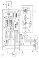
- FIG. 1 is a schematic configuration diagram showing a configuration of an endoscope apparatus according to the present embodiment.
- An endoscope apparatus 1 that is a medical device includes an endoscope 2, a processor 3, and a light source device 4.
- the processor 3 that is a medical processor includes a monitor 5 that is a display device, and a keyboard 6 that is an input device. Is connected.
- the endoscope 2 is connected to the processor 3 by a universal cable 7.
- the light source device 4 is connected to the endoscope 2 so as to supply illumination light, and is connected to the processor 3 so as to receive a control signal.
- the endoscope 2 is detachably connected to the processor 3 by a connector (not shown) of a universal cable 7.
- the endoscope 2 includes an elongated insertion part 11 and an operation part 12. At the distal end portion of the insertion portion 11, an illumination lens 13 and a lens 14 as an objective optical system are provided. A light guide 15 is inserted through the insertion portion 11, and an end face on the distal end side of the light guide 15 is disposed behind the illumination lens 13. The proximal end side of the light guide 15 is connected to the light source device 4 so that the light guide 15 transmits illumination light from the light source device 4.
- a connector (not shown) is provided at the base end portion of the light guide 15, and the light guide 15 of the endoscope 2 is detachably connected to the light source device 4.
- a half mirror 16 is provided on the back surface of the lens 14 as the objective optical system.
- the half mirror 16 functions to direct return light from the living tissue T of the subject to the two imaging elements 17 and 18.
- An imaging unit is provided at the distal end of the insertion unit 11.
- the CCD 17 that is one image pickup device of the image pickup unit is an image pickup device for normal light observation, and is arranged so as to receive light from the half mirror 16 through a lens 19 that functions as a zoom lens.
- the lens 19 is connected to the actuator 21 via a support member 20 that supports the lens 19.
- the CCD 17 is an image sensor for normal light observation. That is, the imaging unit includes a lens 19 that is a zoom lens that varies the observation visual field range.
- the actuator 21 generates a laminated piezoelectric element in which a plurality of piezoelectric layers are laminated, and a laminated piezoelectric element provided in a part of the laminated piezoelectric element, as disclosed in, for example, Japanese Patent Application Laid-Open No. 09-322566. It is an actuator which has a detection part which detects distortion or stress to perform.
- the actuator 21 is driven by a drive signal from a control circuit (described later) of the processor 3.
- the actuator 21 moves the support member 20 along the optical axis of the lens 19, whereby the zoom function by the lens 19 is achieved. Further, the actuator 21 outputs an end position signal indicating that the end of the drive stroke has been reached from the detected strain or stress.
- the terminal position signal output from the actuator 21 is supplied to the processor 3. When this terminal position signal is output from the actuator 21, it indicates that the lens 19 is at the widest position.
- the end position signal from the actuator 21 is held in the processor 3 when a freeze button 23 described later is pressed.
- the lens 19 is in the position at the widest angle based on the end position signal of the actuator 21, but the lens 19 is the most by a limit switch with which the support member 20 contacts, for example. You may make it detect that it exists in the position at the time of a wide angle.
- the CCD 18, which is another imaging element of the imaging unit, is an imaging element for fluorescence observation, which is one of special light observations, and receives light from the half mirror 16 through the excitation light cut filter 22. Are arranged to be.
- the CCD 18 is an image sensor for special light observation.
- the endoscope 2 includes a CCD 17 that is an imaging unit that captures return light that is reflected light of light for normal light observation, and a CCD 18 that is an imaging unit that captures return light of light for special light observation. It has an imaging part.
- the light received by the CCD 17 is return light from the living tissue T, and the return light is reflected light of white light for normal light observation.
- the light received by the CCD 18 is return light from the living tissue T, and the return light is fluorescence emitted from a substance excited by excitation light for fluorescence observation. That is, the CCDs 17 and 18 constitute an imaging unit, that is, an imaging device for imaging the return light of the light irradiated on the living tissue T by the illumination light from the light source device 4.
- the endoscope 2 is not provided with a zoom function for fluorescence observation.
- the angle of view of the image obtained by the CCD 18 is the same as the angle of view of the image obtained by the CCD 17 at the widest angle. Since the lens 14 which is a common objective optical system is used, when the angle of view of the image obtained in the CCD 18 and the angle of view of the image obtained at the widest angle in the CCD 17 are the same, the observation field of view for the two images Match.
- the terminal position signal output from the actuator 21 is input to the control circuit 31. Then, as will be described later, the control circuit 31 determines the coincidence of the observation visual fields for the two images obtained by the CCDs 17 and 18 based on the end position signal.
- the end position signal can be said to be zoom information of the lens 19 that is a zoom lens. Therefore, the control circuit 31 constitutes an observation visual field discrimination unit that discriminates the coincidence of the observation visual fields for the two images. Then, the control circuit 31 that is an observation visual field discrimination unit discriminates the coincidence of the observation visual fields based on zoom information of the zoom lens.
- the operation unit 12 is provided with various switches operated by the surgeon.
- a freeze button 23 and a release button 24 are shown.
- the freeze button 23 is a button for obtaining a still image.
- the release button 24 is a button for storing a still image obtained by freezing in a storage device (not shown).
- An identification information storage unit 25 that stores identification information indicating the type of the endoscope 2 is provided in the operation unit 12.
- the processor 3 includes a control circuit 31, a timing control circuit 32, a switch 33, freeze memories 34 and 35, marker generation and addition circuits 36 and 37, and a synthesis circuit 38.
- the control circuit 31 includes a central processing unit (hereinafter referred to as a CPU) 31a, receives operation signals from the keyboard 6, and controls the entire processor 3 so as to execute various processes based on the received operation signals. Do.
- the control circuit 31 executes various processes designated by the user by executing predetermined software programs stored in a ROM (not shown) in accordance with various commands input to the keyboard 6. It is.
- control circuit 31 also receives various signals from the endoscope 2. Specifically, the terminal position signal from the actuator 21, the operation signals from the freeze button 23 and the release button 24, and the identification information from the identification information storage unit 25 are received.
- FIG. 1 shows only circuits related to the simultaneous display of two still images. Circuits for other functions, for example, drive circuits for driving the CCDs 17 and 18 supplied from the processor 3 and The signal line for the drive signal is omitted.
- control circuit 31 supplies control signals to the timing control circuit 32, the freeze memories 34 and 35, and the marker generation and addition circuits 36 and 37.
- the control circuit 31 When receiving the freeze instruction by pressing the freeze button 23, the control circuit 31 outputs a predetermined signal to the freeze memories 34 and 35.
- the control circuit 31 When receiving a marker display instruction from the keyboard 6, the control circuit 31 outputs a predetermined signal to the marker generation and addition circuits 36 and 37.
- the control circuit 31 reads the identification information in the identification information storage unit 25 of the endoscope 2, supplies a control signal corresponding to the read identification information to the timing control circuit 32, and sets the type of the endoscope 2.
- Various timing signals corresponding thereto are output to the timing control circuit 32.
- the timing control circuit 32 supplies timing signals corresponding to various modes and types of the endoscope 2 to various circuits. In FIG. 1, the timing control circuit 32 supplies a timing signal to the light source device 4 and the switch 33.
- the switch 33 is a circuit that can input two video signals Ia and Ib, and selects and outputs one of the two video signals Ia and Ib based on the timing signal from the timing control circuit 32. . That is, the switch 33 selects two video signals Ia and Ib according to the type of endoscope connected to the processor 3.
- the timing control circuit 32 supplies the switch 33 with a timing signal that always selects and outputs the video signal Ia.
- the freeze memory 34 is a still image memory that stores the video signal output from the switch 33 based on the control signal from the control circuit 31.
- the freeze memory 35 is also based on the control signal from the control circuit 31.
- This is a still image memory for storing the video signal from the CCD 17.
- the normal light observation image obtained by imaging the return light in synchronization with the irradiation of the normal light observation light and the special observation light by the timing control circuit 32, the switch 33, and the freeze memories 34 and 35;
- An image processing unit that generates two images of the special light observation image is configured.
- the marker generation and addition circuits 36 and 37 generate an image signal of a marker to be superimposed on the video signals from the freeze memories 34 and 35, respectively, and perform processing for adding the image signal to the video signal. This is a circuit for outputting to the synthesis circuit 38.
- the marker generation and addition circuits 36 and 37 add a marker to the input video signal based on the control signal from the control circuit 31. That is, each of the marker generation and addition circuits 36 and 37 executes processing for adding or not adding a marker to the input video signal based on the control signal from the control circuit 31. As a result, the marker generation and addition circuits 36 and 37 output an image with or without the marker added.
- the control circuit 31 and the marker generation and addition circuits 36 and 37 generate a marker indicating the position on the living tissue for at least one of the two images based on the determination result of the observation visual field determination unit.
- a marker generation unit is configured.
- control circuit 31 when the control circuit 31 receives a release instruction when the release button 24 is pressed, the control circuit 31 stores the output signals of the freeze memories 34 and 35 or the marker generation and addition circuits 36 and 37 in a storage device (not shown). Execute.
- the synthesizing circuit 38 is a circuit for synthesizing the two images output from the marker generating and adding circuits 36 and 37 so that they are displayed side by side on the screen of the monitor 5 at the same time. Therefore, two images of the normal light observation image and the special light observation image are displayed side by side on the screen of the monitor 5 that receives the video signal from the synthesis circuit 38.
- the control circuit 31 outputs a control signal for simultaneously displaying two images to the synthesis circuit 38.
- the synthesis circuit 38 displays the two images generated by the image processing unit on the screen 5a which is one screen of the monitor 5, and at least one of the two images has the marker generated by the marker generation unit.
- a display unit that superimposes and displays is configured.
- control circuit 31 When the user does not input a command for instructing simultaneous display of two images to the keyboard 6, the control circuit 31 outputs a control signal for displaying one of the two images to the synthesis circuit 38.
- the light source device 4 includes a light source control circuit 41, two LEDs 42 and 43 that are light emitting elements, a half mirror 44, and a condenser lens 45.
- the light source control circuit 41 generates and outputs drive signals to the LEDs 42 and 43 based on the timing signal from the timing control circuit 32.
- the LED 42 is a light emitting element that emits white light for normal light observation
- the LED 43 is a light emitting element that emits excitation light in a predetermined wavelength band for fluorescence observation.
- the light source control circuit 41 supplies predetermined drive signals to the LEDs 42 and 43 alternately, thereby 43 are driven alternately and exclusively. Therefore, the light source device 4 constitutes an illumination unit or an illumination device that can irradiate the living tissue T with light for normal light observation and light for special light observation.
- the illumination light from the LEDs 42 and 43 is directed to the condenser lens 45 through the half mirror 44, and the condenser lens 45 transmits the illumination light to the end face on the proximal end side of the light guide 15 connected to the light source device 4. Condensate. Therefore, the illumination light is emitted from the end surface on the tip side of the light guide 15 through the light guide 15. The illumination light emitted from the end face on the distal end side of the light guide 15 is emitted from the distal end portion of the insertion portion 11 via the illumination lens 13 and illuminates the living tissue T at the observation site.
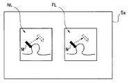
- FIG. 2 is a diagram illustrating a display example of two images.
- FIG. 2 shows two still images that are medical images, that is, a normal light observation image NL and a fluorescence observation image FL, which are displayed side by side on the screen 5a of the monitor 5.
- the control circuit 31 outputs a predetermined control signal to the synthesis circuit 38, and two moving images are displayed on the screen 5 a of the monitor 5.
- the user enlarges and displays the normal light observation image NL by the zoom function before pressing the freeze button 23.
- two still images as shown in FIG. 2 are displayed on the screen 5 a of the monitor 5.
- the user operates the keyboard 6 to display the marker M on the normal light observation image NL, and uses the up / down / left / right arrow keys as shown by dotted lines in FIG.
- the marker M can be positioned at an arbitrary position.
- FIG. 2 shows that the user displays the marker M on the normal light observation image NL, and the marker M is an arrow pointer having an arrow shape and points to a certain point P1 on the image of the living tissue T. Is shown.
- the user can also operate the keyboard 6 to display the marker M on the fluorescence observation image FL.
- the endoscope 2 shown in FIG. 1 uses a lens 14 and a half mirror 16 of a single objective optical system, and the two CCDs 17 and 18 are used for normal light observation images, respectively. This is because a fluorescence observation image is obtained.
- the actuator 21 outputs the terminal position signal, the two observation visual fields of the CCDs 17 and 18 coincide with each other.
- FIG. 3 is a diagram illustrating a display example of two images when the observation fields of view of the two imaging units are coincident.
- the field of view of the normal light observation image NL and the field of view of the fluorescence observation image FL are the same, when the user operates the keyboard 6 to display the marker M on the normal light observation image NL, for example, the same marker M is displayed. Also displayed on the fluorescence observation image FL.
- the two markers M have the same shape and color, but may be slightly different in color and shape.
- the still images acquired in the CCDs 17 and 18 are images of the same observation field.
- the freeze button 23 when the freeze button 23 is pressed and the actuator 21 outputs the end position signal, the two observation fields of view of the CCDs 17 and 18 coincide with each other.
- the marker M is displayed on one of the images, the same marker M is displayed at the same position on the other image.
- the marker M on the other image moves in the same manner as indicated by a dotted line in FIG.
- the surgeon displays the marker M on one image and the same marker M is also displayed on the other image, the surgeon displays the marker M on the two images. It can be seen that the position indicated by is the same position.
- endoscope 2 is detachably connected to the processor 3 and the light source device 4 as described above, other types of endoscopes can be connected to the processor 3 and the light source device 4. ing.
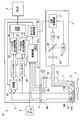
- FIG. 4 is a schematic configuration diagram showing a configuration of an endoscope apparatus 1A in which an endoscope 2A different from the endoscope 2 is connected to a processor 3 and a light source device 4.
- FIG. 4 the same components as those in FIG. In particular, the configurations of the processor 3 and the light source device 4 are the same in FIGS.
- the observation field for the normal light observation image NL may coincide with the observation field for the fluorescence observation image FL.
- the endoscope 2A in FIG. 4 is an endoscope in which the observation field of the normal light observation image NL and the observation field of the fluorescence observation image FL always coincide.
- the endoscope 2A connected to the processor 3 has a lens 14 of one objective optical system and a CCD 17A.
- the processor 3 controls each circuit so that the normal light observation image NL and the fluorescence observation image FL are acquired by the CCD 17A.
- the control circuit 31 can read the identification information in the identification information storage unit 25 of the connected endoscope 2A and determine the type of the connected endoscope 2A. Therefore, the control circuit 31 supplies a control signal corresponding to the determined endoscope type to the timing control circuit 32, and the timing control circuit 32 supplies a timing signal corresponding to the endoscope 2A to the switch 33. To do. In the light source device 4, white light for normal light observation and excitation light for fluorescence observation are alternately output, and in synchronization with the timing, the switch 33 is fluorescence that is return light corresponding to the excitation light. Video signal Ib is selected. That is, the switch 33 intermittently selects and outputs one video signal Ib of the two input signals based on the timing signal from the timing control circuit 32.
- the switch 33 selects the video signal Ib at the same timing as the timing signal that drives the LED 43 and is output to the light source device 4, and freeze memory 34.
- the timing control circuit 32 outputs a timing signal to the switch 33 so as to output to the switch 33.
- the freeze button 23 when the freeze button 23 is pressed, the fluorescence observation image is stored in the freeze memory 34, and the normal light observation image is stored in the freeze memory 35.
- FIG. 5 is a schematic configuration diagram showing a configuration of an endoscope apparatus 1B in which an endoscope 2B different from the endoscope 2 is connected to the processor 3 and the light source device 4.
- FIG. 5 the same components as those in FIG. In particular, the configurations of the processor 3 and the light source device 4 are the same in FIGS. 1 and 5.
- the endoscope 2 shown in FIG. 1 is an endoscope in which the observation visual field for the normal light observation image NL and the observation visual field for the fluorescence observation image FL may coincide with each other depending on the zoom position.
- 2A is an endoscope in which the observation field for the normal light observation image NL always matches the observation field for the fluorescence observation image FL, but the endoscope 2B in FIG. 5 is an observation field for the normal light observation image NL.
- the observation field for the fluorescence observation image FL are endoscopes that do not always coincide.
- an endoscope 2B connected to the processor 3 has two CCDs 17B and 18B that are imaged through different objective optical systems, and the normal light observation image NL is acquired by the CCD 17B.
- the fluorescence observation image FL is acquired by the CCD 18B. Therefore, in the endoscope 2B, the observation field for the normal light observation image NL and the observation field for the fluorescence observation image FL do not always coincide.
- the control circuit 31 can read the identification information in the identification information storage unit 25 of the connected endoscope 2B and determine the type of the connected endoscope 2B. Therefore, the control circuit 31 supplies a control signal corresponding to the determined endoscope type to the timing control circuit 32, and the timing control circuit 32 supplies a timing signal corresponding to the endoscope 2B to the switch 33. To do.
- the switch 33 is fluorescence that is return light corresponding to the excitation light. Select the video signal Ia.
- the switch 33 intermittently selects and outputs one video signal Ia of the two input signals based on the timing signal from the timing control circuit 32.
- the switch 33 selects the video signal Ia and outputs the freeze memory 34 at the same timing as the timing signal for driving the LED 43 output to the light source device 4.
- the timing control circuit 32 outputs a timing signal to the switch 33 so as to output to the switch 33. Therefore, when the freeze button 23 is pressed, the freeze memory 34 stores the fluorescence observation image obtained by imaging with the CCD 18B, and the freeze memory 35 stores the normal light observation image.
- the control circuit 31 reads the identification information in the identification information storage unit 25 of the connected endoscope, and based on the identification information, the two images obtained by the CCDs 17 and 18 are read out. Determine whether the observation fields match or do not match. Therefore, the control circuit 31 configures an observation visual field determination unit that determines the coincidence of the observation visual fields for the two images based on the identification information stored in the identification information storage unit 25.
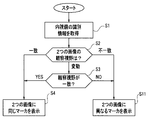
- FIG. 6 is a flowchart illustrating an example of processing of the CPU 31a of the control circuit 31.
- the processing of FIG. 6 is executed. 6 is performed when the CPU 31a reads and executes a software program stored in a storage device such as a ROM (not shown).
- the CPU 31a of the control circuit 31 reads and acquires the identification information in the identification information storage unit 25 of the endoscope connected to the processor 3 (S1). Based on the read identification information, the CPU 31a determines whether the observation visual fields for the two images obtained by the endoscope are always the same, are always inconsistent, or are inconsistent in some cases. Are determined (S2).
- the identification information of the endoscope is information indicating the type of the endoscope, and the endoscope outputs two images whose observation fields always coincide with each other based on the identification information. It is possible to determine whether to output two images that are always inconsistent or to output two images that may match.
- the CPU 31a determines that the connected endoscope is an endoscope that outputs two images in which the observation visual fields may coincide, that is, 2 If it is determined that the endoscope is a endoscope in which at least one of the observation visual fields of one image changes, the process proceeds to S3.
- the connected endoscope is an endoscope 2 as shown in FIG.
- the CPU 31a determines whether or not the observation visual fields match. This determination is made based on the presence / absence of a terminal position signal from the actuator 21. Since the CPU 31a holds or stores the end position signal from the actuator 21 when the freeze button 23 is pressed, the CPU 31a can make the determination of S3.
- the CPU 31a displays the same marker M on both of the two images (S4). As shown in FIG. 3, the user can move the position of the displayed marker M on two images using the up / down / left / right keys of the keyboard 6.
- the CPU 31a displays the marker M on one of the two images (S4).
- the user can move the position of the displayed marker on the image on which the marker M is displayed using the up / down / left / right keys of the keyboard 6.
- the marker M is displayed on the normal light observation image NL.
- the marker M can be displayed on the fluorescence observation image FL by a user instruction.
- the CPU 31a determines that the connected endoscope is an endoscope that outputs two images whose observation visual fields always coincide with each other. If so (S2: match), the process proceeds to S4. In this case, the connected endoscope is an endoscope 2A as shown in FIG. 4, and the observation fields of the two images always coincide with each other. The same marker M is displayed on both (S4).
- the CPU 31a determines that the connected endoscope is an endoscope that outputs two images whose observation visual fields are always inconsistent. In the case (S2: mismatch), the process proceeds to S5. In this case, the connected endoscope is an endoscope 2B as shown in FIG. 5, and the observation field of view of the two images is always inconsistent.
- the marker M is displayed on one side (S5).
- the synthesis circuit 38 displays the same marker M superimposed on each of the two images.
- the marker is superimposed on one of the two images and displayed.
- the same marker M is displayed on the two images, so that a user such as a surgeon has two markers M displayed on the two images. It can be recognized that the same position on the two images is shown.
- the marker M is displayed on only one of the two images, the user can see that the observation fields of view for the two images do not match.
- the same marker M is displayed on the two images when the observation visual fields for the two images match, and one image is displayed when the observation visual fields for the two images do not match.
- the marker M is displayed only on the upper side, and the marker M is not displayed on the other image.
- two markers having different shapes or colors are combined into two images. You may make it display.
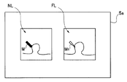
- FIG. 7 is a diagram showing a display example of two images on the screen 5a of the monitor 5 when two markers having different forms or colors are displayed on two images.
- the user operates the keyboard 6 to preset whether to display two markers or only one when the observation visual fields for the two images do not match.
- two observation markers are displayed but are selected or set, when the observation visual fields for the two images are not identical, as shown in FIG.
- a marker Mh having a different color and shape from the marker M is displayed on the fluorescence observation image FL.
- an image like FIG. 3 is displayed.
- the marker Mh is different in shape and color from the marker M, but at least one of the shape and color may be different.
- FIG. 8 is a flowchart showing an example of processing of the CPU 31a of the control circuit 31 for displaying the image of FIG.
- the same reference numerals as those in FIG. 8 are identical reference numerals as those in FIG.
- the synthesis circuit 38 displays the same marker superimposed on each of the two images, and the observation visual field determination unit When it is determined that the observation fields of view for the two images are inconsistent, different markers are superimposed and displayed on the two images. Therefore, the user can recognize whether or not the two markers indicate the same position on the two images by the form or color of the marker displayed on the two images.
- a medical device capable of displaying that two markers displayed in two images indicate the same position on the two images, and a marker display control method in a medical image And a medical processor can be provided.
- a medical processor can be provided.
- the surgeon sees and compares the lesion area on two images, if the observation field is found to match, the surgeon can correctly recognize the lesion area. Inspection, treatment, etc. can be performed.
- a zoom function is provided in one of the two imaging units.
- the zoom amount may be detected by the control circuit 31 based on the outputs of the two sensors that detect the outputs of the two actuators, and the coincidence of the visual field ranges for the two images may be determined.
- the above example is an example in which markers are displayed on two still images obtained by freezing using two freeze memories, but two moving images are used using a frame memory for moving images.
- the same marker may be displayed on the two moving images.
Abstract
La présente invention concerne le processeur (3) d'un appareil endoscopique (1), qui est un instrument médical, qui : génère deux images obtenues par imagerie de lumière de retour, une image d'observation lumineuse normale et une lumière d'observation lumineuse spéciale ; détermine la coïncidence des champs visuels des deux images ; génère un marqueur (M) représentant une position sur le tissu vivant pour au moins une des deux images en se basant sur les résultats de la détermination ; affiche les deux images générées sur un seul écran sur un moniteur (5) ; et affiche le marqueur généré (M) superposé sur au moins l'une des deux images.
Priority Applications (4)
| Application Number | Priority Date | Filing Date | Title |
|---|---|---|---|
| EP12786034.4A EP2649929B1 (fr) | 2011-05-17 | 2012-03-23 | Instrument médical, procédé de commande d'affichage de marqueur sur une image médicale, et processeur médical |
| CN201280004932.2A CN103298393B (zh) | 2011-05-17 | 2012-03-23 | 医疗设备、医疗图像中的标记显示控制方法以及医疗用处理器 |
| JP2012552203A JP5274724B2 (ja) | 2011-05-17 | 2012-03-23 | 医療機器、医療用プロセッサの作動方法及び医療用プロセッサ |
| US13/683,584 US8876700B2 (en) | 2011-05-17 | 2012-11-21 | Medical apparatus, method for controlling marker display in medical image and medical processor |
Applications Claiming Priority (2)
| Application Number | Priority Date | Filing Date | Title |
|---|---|---|---|
| JP2011110728 | 2011-05-17 | ||
| JP2011-110728 | 2011-05-17 |
Related Child Applications (1)
| Application Number | Title | Priority Date | Filing Date |
|---|---|---|---|
| US13/683,584 Continuation US8876700B2 (en) | 2011-05-17 | 2012-11-21 | Medical apparatus, method for controlling marker display in medical image and medical processor |
Publications (1)
| Publication Number | Publication Date |
|---|---|
| WO2012157338A1 true WO2012157338A1 (fr) | 2012-11-22 |
Family
ID=47176679
Family Applications (1)
| Application Number | Title | Priority Date | Filing Date |
|---|---|---|---|
| PCT/JP2012/057473 WO2012157338A1 (fr) | 2011-05-17 | 2012-03-23 | Instrument médical, procédé de commande d'affichage de marqueur sur des images médicales, et processeur médical |
Country Status (5)
| Country | Link |
|---|---|
| US (1) | US8876700B2 (fr) |
| EP (1) | EP2649929B1 (fr) |
| JP (1) | JP5274724B2 (fr) |
| CN (1) | CN103298393B (fr) |
| WO (1) | WO2012157338A1 (fr) |
Cited By (5)
| Publication number | Priority date | Publication date | Assignee | Title |
|---|---|---|---|---|
| WO2014168128A1 (fr) * | 2013-04-12 | 2014-10-16 | オリンパスメディカルシステムズ株式会社 | Système d'endoscope et procédé de fonctionnement pour système d'endoscope |
| CN104582559A (zh) * | 2013-03-06 | 2015-04-29 | 奥林巴斯医疗株式会社 | 内窥镜系统和内窥镜系统的工作方法 |
| WO2016199273A1 (fr) * | 2015-06-11 | 2016-12-15 | オリンパス株式会社 | Dispositif d'endoscope et procédé de fonctionnement de dispositif d'endoscope |
| JPWO2017038321A1 (ja) * | 2015-09-03 | 2018-06-14 | オリンパス株式会社 | 内視鏡装置及び内視鏡装置の表示変更制御方法 |
| JPWO2019235195A1 (ja) * | 2018-06-04 | 2021-06-03 | 富士フイルム株式会社 | 画像処理装置、内視鏡システム、及び画像処理方法 |
Families Citing this family (10)
| Publication number | Priority date | Publication date | Assignee | Title |
|---|---|---|---|---|
| WO2012046856A1 (fr) * | 2010-10-08 | 2012-04-12 | オリンパスメディカルシステムズ株式会社 | Dispositif d'imagerie |
| JP5980604B2 (ja) * | 2012-07-18 | 2016-08-31 | オリンパス株式会社 | 内視鏡システム |
| JP2014128394A (ja) * | 2012-12-28 | 2014-07-10 | Hoya Corp | 内視鏡装置 |
| US10405733B2 (en) * | 2015-04-30 | 2019-09-10 | Sony Olympus Medical Solutions Inc. | Medical signal processing device and medical observation system |
| JP6660707B2 (ja) * | 2015-10-23 | 2020-03-11 | Hoya株式会社 | 内視鏡システム |
| US10606149B2 (en) * | 2016-05-25 | 2020-03-31 | Sony Corporation | Information processing device, information processing method, and program |
| JP7073618B2 (ja) * | 2016-09-23 | 2022-05-24 | ソニーグループ株式会社 | 制御装置、制御方法及び医療用システム |
| JP6925501B2 (ja) * | 2018-03-02 | 2021-08-25 | 富士フイルム株式会社 | 画像処理装置及び内視鏡システム |
| JP7265823B2 (ja) * | 2018-10-19 | 2023-04-27 | キヤノン株式会社 | 撮像装置及びプログラム |
| CN114343873B (zh) * | 2022-01-07 | 2023-04-18 | 苏州康多机器人有限公司 | 一种内窥镜手术监测系统及方法 |
Citations (6)
| Publication number | Priority date | Publication date | Assignee | Title |
|---|---|---|---|---|
| JPH0556918A (ja) * | 1991-09-05 | 1993-03-09 | Olympus Optical Co Ltd | 内視鏡装置 |
| JPH09322566A (ja) | 1996-06-04 | 1997-12-12 | Olympus Optical Co Ltd | 圧電アクチュエータ |
| JP2006230906A (ja) * | 2005-02-28 | 2006-09-07 | Toshiba Corp | 医用診断システム、医用診断装置及び内視鏡 |
| JP2007020728A (ja) * | 2005-07-13 | 2007-02-01 | Olympus Medical Systems Corp | 画像処理装置 |
| JP2010075368A (ja) * | 2008-09-25 | 2010-04-08 | Fujifilm Corp | 電子内視鏡装置および方法並びにプログラム |
| JP2010172673A (ja) | 2009-02-02 | 2010-08-12 | Fujifilm Corp | 内視鏡システム、内視鏡用プロセッサ装置、並びに内視鏡検査支援方法 |
Family Cites Families (21)
| Publication number | Priority date | Publication date | Assignee | Title |
|---|---|---|---|---|
| US4895431A (en) * | 1986-11-13 | 1990-01-23 | Olympus Optical Co., Ltd. | Method of processing endoscopic images |
| AU617431B2 (en) * | 1988-03-07 | 1991-11-28 | Sharp Kabushiki Kaisha | Interlocked zooming apparatus |
| US5583566A (en) * | 1989-05-12 | 1996-12-10 | Olympus Optical Co., Ltd. | Combined medical image and data transmission with data storage, in which character/diagram information is transmitted with video data |
| JPH04307024A (ja) * | 1991-04-02 | 1992-10-29 | Olympus Optical Co Ltd | 電子内視鏡装置 |
| US5662584A (en) * | 1994-10-07 | 1997-09-02 | Vista Medical Technologies, Inc. | Endoscope with position display for zoom lens unit and imaging device |
| US5672877A (en) * | 1996-03-27 | 1997-09-30 | Adac Laboratories | Coregistration of multi-modality data in a medical imaging system |
| US6404906B2 (en) * | 1997-03-03 | 2002-06-11 | Bacus Research Laboratories,Inc. | Method and apparatus for acquiring and reconstructing magnified specimen images from a computer-controlled microscope |
| US6293911B1 (en) * | 1996-11-20 | 2001-09-25 | Olympus Optical Co., Ltd. | Fluorescent endoscope system enabling simultaneous normal light observation and fluorescence observation in infrared spectrum |
| US7179222B2 (en) * | 1996-11-20 | 2007-02-20 | Olympus Corporation | Fluorescent endoscope system enabling simultaneous achievement of normal light observation based on reflected light and fluorescence observation based on light with wavelengths in infrared spectrum |
| US6322497B1 (en) * | 1998-12-25 | 2001-11-27 | Asahi Kogaku Kogyo Kabushiki Kaisha | Electronic endoscope |
| JP4009639B2 (ja) * | 2002-07-31 | 2007-11-21 | オリンパス株式会社 | 内視鏡装置、内視鏡装置のナビゲーション方法、内視鏡画像の表示方法、及び内視鏡用画像表示プログラム |
| US7520854B2 (en) * | 2004-07-14 | 2009-04-21 | Olympus Corporation | Endoscope system allowing movement of a display image |
| US20060173358A1 (en) * | 2005-01-11 | 2006-08-03 | Olympus Corporation | Fluorescence observation endoscope apparatus and fluorescence observation method |
| JP2007020727A (ja) * | 2005-07-13 | 2007-02-01 | Olympus Medical Systems Corp | 画像処理装置 |
| US20080091065A1 (en) * | 2006-10-04 | 2008-04-17 | Olympus Medical Systems Corporation | Medical image processing apparatus, endoscope system and medical image processing system |
| US8672836B2 (en) * | 2007-01-31 | 2014-03-18 | The Penn State Research Foundation | Method and apparatus for continuous guidance of endoscopy |
| US8270691B2 (en) * | 2007-10-09 | 2012-09-18 | Siemens Aktiengesellschaft | Method for fusing images acquired from a plurality of different image acquiring modalities |
| EP2207056B1 (fr) * | 2007-10-30 | 2013-01-09 | Olympus Corporation | Dispositif endoscopique |
| US20090213140A1 (en) * | 2008-02-26 | 2009-08-27 | Masaru Ito | Medical support control system |
| US8531479B2 (en) * | 2009-06-12 | 2013-09-10 | Olympus Corporation | Endoscope apparatus and program |
| US20120130171A1 (en) * | 2010-11-18 | 2012-05-24 | C2Cure Inc. | Endoscope guidance based on image matching |
-
2012
- 2012-03-23 CN CN201280004932.2A patent/CN103298393B/zh active Active
- 2012-03-23 JP JP2012552203A patent/JP5274724B2/ja active Active
- 2012-03-23 WO PCT/JP2012/057473 patent/WO2012157338A1/fr active Application Filing
- 2012-03-23 EP EP12786034.4A patent/EP2649929B1/fr not_active Not-in-force
- 2012-11-21 US US13/683,584 patent/US8876700B2/en active Active
Patent Citations (6)
| Publication number | Priority date | Publication date | Assignee | Title |
|---|---|---|---|---|
| JPH0556918A (ja) * | 1991-09-05 | 1993-03-09 | Olympus Optical Co Ltd | 内視鏡装置 |
| JPH09322566A (ja) | 1996-06-04 | 1997-12-12 | Olympus Optical Co Ltd | 圧電アクチュエータ |
| JP2006230906A (ja) * | 2005-02-28 | 2006-09-07 | Toshiba Corp | 医用診断システム、医用診断装置及び内視鏡 |
| JP2007020728A (ja) * | 2005-07-13 | 2007-02-01 | Olympus Medical Systems Corp | 画像処理装置 |
| JP2010075368A (ja) * | 2008-09-25 | 2010-04-08 | Fujifilm Corp | 電子内視鏡装置および方法並びにプログラム |
| JP2010172673A (ja) | 2009-02-02 | 2010-08-12 | Fujifilm Corp | 内視鏡システム、内視鏡用プロセッサ装置、並びに内視鏡検査支援方法 |
Non-Patent Citations (1)
| Title |
|---|
| See also references of EP2649929A4 |
Cited By (9)
| Publication number | Priority date | Publication date | Assignee | Title |
|---|---|---|---|---|
| CN104582559A (zh) * | 2013-03-06 | 2015-04-29 | 奥林巴斯医疗株式会社 | 内窥镜系统和内窥镜系统的工作方法 |
| WO2014168128A1 (fr) * | 2013-04-12 | 2014-10-16 | オリンパスメディカルシステムズ株式会社 | Système d'endoscope et procédé de fonctionnement pour système d'endoscope |
| CN105050479A (zh) * | 2013-04-12 | 2015-11-11 | 奥林巴斯株式会社 | 内窥镜系统以及内窥镜系统的动作方法 |
| US9538907B2 (en) | 2013-04-12 | 2017-01-10 | Olympus Corporation | Endoscope system and actuation method for displaying an organ model image pasted with an endoscopic image |
| JPWO2014168128A1 (ja) * | 2013-04-12 | 2017-02-16 | オリンパス株式会社 | 内視鏡システム及び内視鏡システムの作動方法 |
| WO2016199273A1 (fr) * | 2015-06-11 | 2016-12-15 | オリンパス株式会社 | Dispositif d'endoscope et procédé de fonctionnement de dispositif d'endoscope |
| JPWO2016199273A1 (ja) * | 2015-06-11 | 2018-03-29 | オリンパス株式会社 | 内視鏡装置及び内視鏡装置の作動方法 |
| JPWO2017038321A1 (ja) * | 2015-09-03 | 2018-06-14 | オリンパス株式会社 | 内視鏡装置及び内視鏡装置の表示変更制御方法 |
| JPWO2019235195A1 (ja) * | 2018-06-04 | 2021-06-03 | 富士フイルム株式会社 | 画像処理装置、内視鏡システム、及び画像処理方法 |
Also Published As
| Publication number | Publication date |
|---|---|
| EP2649929A1 (fr) | 2013-10-16 |
| CN103298393A (zh) | 2013-09-11 |
| JP5274724B2 (ja) | 2013-08-28 |
| EP2649929A4 (fr) | 2014-03-05 |
| US8876700B2 (en) | 2014-11-04 |
| CN103298393B (zh) | 2015-09-16 |
| US20130158352A1 (en) | 2013-06-20 |
| EP2649929B1 (fr) | 2015-07-01 |
| JPWO2012157338A1 (ja) | 2014-07-31 |
Similar Documents
| Publication | Publication Date | Title |
|---|---|---|
| JP5274724B2 (ja) | 医療機器、医療用プロセッサの作動方法及び医療用プロセッサ | |
| JP5810248B2 (ja) | 内視鏡システム | |
| KR100954475B1 (ko) | 내시경 | |
| JP4856286B2 (ja) | 内視鏡システム | |
| CN113395928A (zh) | 增强医疗视觉系统和方法 | |
| JP6001219B1 (ja) | 内視鏡システム | |
| US20070013771A1 (en) | Image processing device | |
| JPWO2019239942A1 (ja) | 手術用観察装置、手術用観察方法、手術用光源装置、及び手術用の光照射方法 | |
| JP5675496B2 (ja) | 医療機器及び医療用プロセッサ | |
| WO2020008920A1 (fr) | Système d'observation médicale, dispositif d'observation médicale, et procédé d'entraînement de dispositif d'observation médicale | |
| JP2007236598A (ja) | プロセッサおよび電子内視鏡システム | |
| WO2018180068A1 (fr) | Dispositif d'imagerie médicale et endoscope | |
| JP2021097720A (ja) | 内視鏡及びアームシステム | |
| WO2020203225A1 (fr) | Système médical, dispositif et procédé de traitement d'informations | |
| US20220022728A1 (en) | Medical system, information processing device, and information processing method | |
| WO2020009127A1 (fr) | Système d'observation médicale, dispositif d'observation médicale et procédé de commande de dispositif d'observation médicale | |
| JP6663692B2 (ja) | 画像処理装置、内視鏡システム、及び画像処理装置の制御方法 | |
| WO2018043205A1 (fr) | Dispositif de traitement d'image médicale, procédé de traitement d'image médicale, et programme | |
| JP2001238205A (ja) | 内視鏡システム | |
| WO2020203034A1 (fr) | Système endoscopique | |
| WO2018220930A1 (fr) | Dispositif de traitement d'image | |
| WO2022113811A1 (fr) | Système d'intervention chirurgicale, dispositif de commande d'intervention chirurgicale, procédé de commande et programme | |
| WO2022201933A1 (fr) | Système d'observation intravitréenne, système d'observation, procédé d'observation intravitréenne et dispositif d'observation intravitréenne | |
| JP2017086549A (ja) | 走査型内視鏡装置 | |
| JP2001109445A (ja) | 顔面装着型映像表示装置 |
Legal Events
| Date | Code | Title | Description |
|---|---|---|---|
| ENP | Entry into the national phase |
Ref document number: 2012552203 Country of ref document: JP Kind code of ref document: A |
|
| 121 | Ep: the epo has been informed by wipo that ep was designated in this application |
Ref document number: 12786034 Country of ref document: EP Kind code of ref document: A1 |
|
| WWE | Wipo information: entry into national phase |
Ref document number: 2012786034 Country of ref document: EP |
|
| NENP | Non-entry into the national phase |
Ref country code: DE |