WO2012157338A1 - Medical instrument, method for controlling marker display in medical images, and medical processor - Google Patents
Medical instrument, method for controlling marker display in medical images, and medical processor Download PDFInfo
- Publication number
- WO2012157338A1 WO2012157338A1 PCT/JP2012/057473 JP2012057473W WO2012157338A1 WO 2012157338 A1 WO2012157338 A1 WO 2012157338A1 JP 2012057473 W JP2012057473 W JP 2012057473W WO 2012157338 A1 WO2012157338 A1 WO 2012157338A1
- Authority
- WO
- WIPO (PCT)
- Prior art keywords
- observation
- images
- light
- marker
- image
- Prior art date
Links
Images


Classifications
-
- A—HUMAN NECESSITIES
- A61—MEDICAL OR VETERINARY SCIENCE; HYGIENE
- A61B—DIAGNOSIS; SURGERY; IDENTIFICATION
- A61B1/00—Instruments for performing medical examinations of the interior of cavities or tubes of the body by visual or photographical inspection, e.g. endoscopes; Illuminating arrangements therefor
- A61B1/00002—Operational features of endoscopes
- A61B1/00043—Operational features of endoscopes provided with output arrangements
- A61B1/00045—Display arrangement
- A61B1/0005—Display arrangement combining images e.g. side-by-side, superimposed or tiled
-
- A—HUMAN NECESSITIES
- A61—MEDICAL OR VETERINARY SCIENCE; HYGIENE
- A61B—DIAGNOSIS; SURGERY; IDENTIFICATION
- A61B1/00—Instruments for performing medical examinations of the interior of cavities or tubes of the body by visual or photographical inspection, e.g. endoscopes; Illuminating arrangements therefor
- A61B1/00002—Operational features of endoscopes
- A61B1/00004—Operational features of endoscopes characterised by electronic signal processing
- A61B1/00006—Operational features of endoscopes characterised by electronic signal processing of control signals
-
- A—HUMAN NECESSITIES
- A61—MEDICAL OR VETERINARY SCIENCE; HYGIENE
- A61B—DIAGNOSIS; SURGERY; IDENTIFICATION
- A61B1/00—Instruments for performing medical examinations of the interior of cavities or tubes of the body by visual or photographical inspection, e.g. endoscopes; Illuminating arrangements therefor
- A61B1/00002—Operational features of endoscopes
- A61B1/00004—Operational features of endoscopes characterised by electronic signal processing
- A61B1/00009—Operational features of endoscopes characterised by electronic signal processing of image signals during a use of endoscope
- A61B1/000094—Operational features of endoscopes characterised by electronic signal processing of image signals during a use of endoscope extracting biological structures
-
- A—HUMAN NECESSITIES
- A61—MEDICAL OR VETERINARY SCIENCE; HYGIENE
- A61B—DIAGNOSIS; SURGERY; IDENTIFICATION
- A61B1/00—Instruments for performing medical examinations of the interior of cavities or tubes of the body by visual or photographical inspection, e.g. endoscopes; Illuminating arrangements therefor
- A61B1/00002—Operational features of endoscopes
- A61B1/00039—Operational features of endoscopes provided with input arrangements for the user
- A61B1/0004—Operational features of endoscopes provided with input arrangements for the user for electronic operation
-
- A—HUMAN NECESSITIES
- A61—MEDICAL OR VETERINARY SCIENCE; HYGIENE
- A61B—DIAGNOSIS; SURGERY; IDENTIFICATION
- A61B1/00—Instruments for performing medical examinations of the interior of cavities or tubes of the body by visual or photographical inspection, e.g. endoscopes; Illuminating arrangements therefor
- A61B1/00112—Connection or coupling means
- A61B1/00114—Electrical cables in or with an endoscope
-
- A—HUMAN NECESSITIES
- A61—MEDICAL OR VETERINARY SCIENCE; HYGIENE
- A61B—DIAGNOSIS; SURGERY; IDENTIFICATION
- A61B1/00—Instruments for performing medical examinations of the interior of cavities or tubes of the body by visual or photographical inspection, e.g. endoscopes; Illuminating arrangements therefor
- A61B1/00112—Connection or coupling means
- A61B1/00117—Optical cables in or with an endoscope
-
- A—HUMAN NECESSITIES
- A61—MEDICAL OR VETERINARY SCIENCE; HYGIENE
- A61B—DIAGNOSIS; SURGERY; IDENTIFICATION
- A61B1/00—Instruments for performing medical examinations of the interior of cavities or tubes of the body by visual or photographical inspection, e.g. endoscopes; Illuminating arrangements therefor
- A61B1/00112—Connection or coupling means
- A61B1/00121—Connectors, fasteners and adapters, e.g. on the endoscope handle
- A61B1/00124—Connectors, fasteners and adapters, e.g. on the endoscope handle electrical, e.g. electrical plug-and-socket connection
-
- A—HUMAN NECESSITIES
- A61—MEDICAL OR VETERINARY SCIENCE; HYGIENE
- A61B—DIAGNOSIS; SURGERY; IDENTIFICATION
- A61B1/00—Instruments for performing medical examinations of the interior of cavities or tubes of the body by visual or photographical inspection, e.g. endoscopes; Illuminating arrangements therefor
- A61B1/00112—Connection or coupling means
- A61B1/00121—Connectors, fasteners and adapters, e.g. on the endoscope handle
- A61B1/00126—Connectors, fasteners and adapters, e.g. on the endoscope handle optical, e.g. for light supply cables
-
- A—HUMAN NECESSITIES
- A61—MEDICAL OR VETERINARY SCIENCE; HYGIENE
- A61B—DIAGNOSIS; SURGERY; IDENTIFICATION
- A61B1/00—Instruments for performing medical examinations of the interior of cavities or tubes of the body by visual or photographical inspection, e.g. endoscopes; Illuminating arrangements therefor
- A61B1/00163—Optical arrangements
- A61B1/00188—Optical arrangements with focusing or zooming features
- A61B1/0019—Optical arrangements with focusing or zooming features characterised by variable lenses
-
- A—HUMAN NECESSITIES
- A61—MEDICAL OR VETERINARY SCIENCE; HYGIENE
- A61B—DIAGNOSIS; SURGERY; IDENTIFICATION
- A61B1/00—Instruments for performing medical examinations of the interior of cavities or tubes of the body by visual or photographical inspection, e.g. endoscopes; Illuminating arrangements therefor
- A61B1/00163—Optical arrangements
- A61B1/00193—Optical arrangements adapted for stereoscopic vision
-
- A—HUMAN NECESSITIES
- A61—MEDICAL OR VETERINARY SCIENCE; HYGIENE
- A61B—DIAGNOSIS; SURGERY; IDENTIFICATION
- A61B1/00—Instruments for performing medical examinations of the interior of cavities or tubes of the body by visual or photographical inspection, e.g. endoscopes; Illuminating arrangements therefor
- A61B1/04—Instruments for performing medical examinations of the interior of cavities or tubes of the body by visual or photographical inspection, e.g. endoscopes; Illuminating arrangements therefor combined with photographic or television appliances
- A61B1/043—Instruments for performing medical examinations of the interior of cavities or tubes of the body by visual or photographical inspection, e.g. endoscopes; Illuminating arrangements therefor combined with photographic or television appliances for fluorescence imaging
-
- A—HUMAN NECESSITIES
- A61—MEDICAL OR VETERINARY SCIENCE; HYGIENE
- A61B—DIAGNOSIS; SURGERY; IDENTIFICATION
- A61B1/00—Instruments for performing medical examinations of the interior of cavities or tubes of the body by visual or photographical inspection, e.g. endoscopes; Illuminating arrangements therefor
- A61B1/06—Instruments for performing medical examinations of the interior of cavities or tubes of the body by visual or photographical inspection, e.g. endoscopes; Illuminating arrangements therefor with illuminating arrangements
- A61B1/0638—Instruments for performing medical examinations of the interior of cavities or tubes of the body by visual or photographical inspection, e.g. endoscopes; Illuminating arrangements therefor with illuminating arrangements providing two or more wavelengths
-
- A—HUMAN NECESSITIES
- A61—MEDICAL OR VETERINARY SCIENCE; HYGIENE
- A61B—DIAGNOSIS; SURGERY; IDENTIFICATION
- A61B1/00—Instruments for performing medical examinations of the interior of cavities or tubes of the body by visual or photographical inspection, e.g. endoscopes; Illuminating arrangements therefor
- A61B1/00002—Operational features of endoscopes
- A61B1/0002—Operational features of endoscopes provided with data storages
-
- A—HUMAN NECESSITIES
- A61—MEDICAL OR VETERINARY SCIENCE; HYGIENE
- A61B—DIAGNOSIS; SURGERY; IDENTIFICATION
- A61B1/00—Instruments for performing medical examinations of the interior of cavities or tubes of the body by visual or photographical inspection, e.g. endoscopes; Illuminating arrangements therefor
- A61B1/00002—Operational features of endoscopes
- A61B1/00059—Operational features of endoscopes provided with identification means for the endoscope
-
- A—HUMAN NECESSITIES
- A61—MEDICAL OR VETERINARY SCIENCE; HYGIENE
- A61B—DIAGNOSIS; SURGERY; IDENTIFICATION
- A61B1/00—Instruments for performing medical examinations of the interior of cavities or tubes of the body by visual or photographical inspection, e.g. endoscopes; Illuminating arrangements therefor
- A61B1/00163—Optical arrangements
- A61B1/00188—Optical arrangements with focusing or zooming features
-
- A—HUMAN NECESSITIES
- A61—MEDICAL OR VETERINARY SCIENCE; HYGIENE
- A61B—DIAGNOSIS; SURGERY; IDENTIFICATION
- A61B1/00—Instruments for performing medical examinations of the interior of cavities or tubes of the body by visual or photographical inspection, e.g. endoscopes; Illuminating arrangements therefor
- A61B1/04—Instruments for performing medical examinations of the interior of cavities or tubes of the body by visual or photographical inspection, e.g. endoscopes; Illuminating arrangements therefor combined with photographic or television appliances
- A61B1/05—Instruments for performing medical examinations of the interior of cavities or tubes of the body by visual or photographical inspection, e.g. endoscopes; Illuminating arrangements therefor combined with photographic or television appliances characterised by the image sensor, e.g. camera, being in the distal end portion
- A61B1/051—Details of CCD assembly
-
- A—HUMAN NECESSITIES
- A61—MEDICAL OR VETERINARY SCIENCE; HYGIENE
- A61B—DIAGNOSIS; SURGERY; IDENTIFICATION
- A61B1/00—Instruments for performing medical examinations of the interior of cavities or tubes of the body by visual or photographical inspection, e.g. endoscopes; Illuminating arrangements therefor
- A61B1/06—Instruments for performing medical examinations of the interior of cavities or tubes of the body by visual or photographical inspection, e.g. endoscopes; Illuminating arrangements therefor with illuminating arrangements
- A61B1/0661—Endoscope light sources
- A61B1/0669—Endoscope light sources at proximal end of an endoscope
-
- A—HUMAN NECESSITIES
- A61—MEDICAL OR VETERINARY SCIENCE; HYGIENE
- A61B—DIAGNOSIS; SURGERY; IDENTIFICATION
- A61B1/00—Instruments for performing medical examinations of the interior of cavities or tubes of the body by visual or photographical inspection, e.g. endoscopes; Illuminating arrangements therefor
- A61B1/06—Instruments for performing medical examinations of the interior of cavities or tubes of the body by visual or photographical inspection, e.g. endoscopes; Illuminating arrangements therefor with illuminating arrangements
- A61B1/0661—Endoscope light sources
- A61B1/0684—Endoscope light sources using light emitting diodes [LED]
-
- A—HUMAN NECESSITIES
- A61—MEDICAL OR VETERINARY SCIENCE; HYGIENE
- A61B—DIAGNOSIS; SURGERY; IDENTIFICATION
- A61B1/00—Instruments for performing medical examinations of the interior of cavities or tubes of the body by visual or photographical inspection, e.g. endoscopes; Illuminating arrangements therefor
- A61B1/06—Instruments for performing medical examinations of the interior of cavities or tubes of the body by visual or photographical inspection, e.g. endoscopes; Illuminating arrangements therefor with illuminating arrangements
- A61B1/07—Instruments for performing medical examinations of the interior of cavities or tubes of the body by visual or photographical inspection, e.g. endoscopes; Illuminating arrangements therefor with illuminating arrangements using light-conductive means, e.g. optical fibres
-
- A—HUMAN NECESSITIES
- A61—MEDICAL OR VETERINARY SCIENCE; HYGIENE
- A61B—DIAGNOSIS; SURGERY; IDENTIFICATION
- A61B90/00—Instruments, implements or accessories specially adapted for surgery or diagnosis and not covered by any of the groups A61B1/00 - A61B50/00, e.g. for luxation treatment or for protecting wound edges
- A61B90/36—Image-producing devices or illumination devices not otherwise provided for
- A61B2090/364—Correlation of different images or relation of image positions in respect to the body
-
- F—MECHANICAL ENGINEERING; LIGHTING; HEATING; WEAPONS; BLASTING
- F04—POSITIVE - DISPLACEMENT MACHINES FOR LIQUIDS; PUMPS FOR LIQUIDS OR ELASTIC FLUIDS
- F04C—ROTARY-PISTON, OR OSCILLATING-PISTON, POSITIVE-DISPLACEMENT MACHINES FOR LIQUIDS; ROTARY-PISTON, OR OSCILLATING-PISTON, POSITIVE-DISPLACEMENT PUMPS
- F04C2270/00—Control; Monitoring or safety arrangements
- F04C2270/04—Force
- F04C2270/041—Controlled or regulated
Definitions
- the present invention relates to a medical device, a marker display control method for a medical image, and a medical processor, and more particularly to a medical device that can display a marker on an image, a marker display control method for a medical image, and a medical processor.
- an endoscope apparatus monitors an image of a living tissue obtained by inserting an elongated flexible insertion portion into a body cavity of a subject and imaging with an imaging element provided at the distal end of the insertion portion. It is a medical device that can be displayed above. By looking at the medical image, the operator can perform diagnosis, treatment, etc. of the observation site.
- Some medical devices can display two images on one monitor when displaying medical images on the monitor.
- some endoscope apparatuses can acquire a normal light observation image and a special light observation image for the same site to be examined. Therefore, the surgeon can perform diagnosis, treatment, and the like by displaying the normal light observation image and the special light observation image side by side on the monitor and displaying them simultaneously.
- an endoscope apparatus having a function of displaying a marker on a displayed image has been proposed or put into practical use. The surgeon can clearly point out an arbitrary position on the screen using the marker.
- a user such as an operator can display a marker at a desired position on one displayed image.
- the positions indicated by the two markers are The user has not been able to confirm whether or not the two images match each other on the living tissue.
- One of the two images is enlarged by a zoom operation, or the two images are images obtained by two imaging units having different fields of view, so that they are displayed on the two images 2
- the user looking at the monitor does not know whether the two markers indicate the same position on the two images.
- the present invention has been made in view of such problems, and in medical devices and medical images capable of displaying that two markers displayed on two images indicate the same position on the two images.
- An object is to provide a marker display control method and a medical processor.
- the medical device of one embodiment of the present invention includes a lighting unit that can irradiate a biological tissue with light for normal light observation and light for special light observation, and a return of the light irradiated on the biological tissue by the lighting unit.
- An image capturing unit that captures light
- an image processing unit that generates two images of a normal light observation image and a special light observation image obtained by capturing the return light, and the observation visual field match between the two images
- An observation visual field discrimination unit for discriminating; a marker generation unit for generating a marker indicating a position on the living tissue for at least one of the two images based on a discrimination result of the observation visual field discrimination unit; and the image processing
- a display unit that displays the two images generated by the unit on one screen of a display device, and displays the marker generated by the marker generation unit on at least one of the two images.
- the marker display control method in the medical image of one embodiment of the present invention is a return of light irradiated on the living tissue by an illumination unit that can irradiate the living tissue with light for normal light observation and light for special light observation.
- Two images, a normal light observation image and a special light observation image obtained by imaging light, are generated, the observation visual field coincidence between the two images is determined, and the 2 based on the observation visual field determination result
- a marker indicating a position on the living tissue is generated for at least one of the two images, the generated two images are displayed on one screen of a display device, and at least one of the two images is displayed.
- the marker generated by the marker generator is superimposed and displayed.
- the medical processor of one embodiment of the present invention images the return light of the light irradiated on the living tissue by an illumination unit that can irradiate the living tissue with light for normal light observation and light for special light observation.
- a medical processor for processing an image picked up by the image pickup unit, the image processing unit for generating two images of a normal light observation image and a special light observation image obtained by imaging the return light;
- An observation visual field discriminating unit for discriminating coincidence of observation visual fields for two images, and generating a marker indicating a position on the living tissue for at least one of the two images based on a discrimination result of the observation visual field discriminating unit
- a marker generating unit that performs the display, and the two images generated by the image processing unit are displayed on one screen of the display device, and at least one of the two images is generated by the marker generating unit.
- a display unit for displaying and superimposing the marker.
- 1 is a schematic configuration diagram showing a configuration of an endoscope apparatus according to an embodiment of the present invention. It is a figure which shows the example of a display of two images concerning embodiment of this invention. It is a figure which shows the example of a display of two images when the observation visual field of the two image pick-up parts concerning embodiment of this invention corresponds.
- 1 is a schematic configuration diagram showing a configuration of an endoscope apparatus 1A in which an endoscope 2A different from an endoscope 2 according to an embodiment of the present invention is connected to a processor 3 and a light source device 4.
- FIG. 1 It is a typical block diagram which shows the structure of the endoscope apparatus 1B by which the endoscope 2B different from the endoscope 2 connected to the processor 3 and the light source device 4 concerning embodiment of this invention.
- FIG. 1 It is a flowchart which shows the example of a process of CPU31a of the control circuit 31 concerning embodiment of this invention.
- the figure which shows the example of a display of two images on the screen 5a of the monitor 5 at the time of making it display two markers from which at least 1 of the form or color which concerns on embodiment of this invention mutually differs in two images. is there.
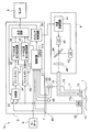
- FIG. 1 is a schematic configuration diagram showing a configuration of an endoscope apparatus according to the present embodiment.
- An endoscope apparatus 1 that is a medical device includes an endoscope 2, a processor 3, and a light source device 4.
- the processor 3 that is a medical processor includes a monitor 5 that is a display device, and a keyboard 6 that is an input device. Is connected.
- the endoscope 2 is connected to the processor 3 by a universal cable 7.
- the light source device 4 is connected to the endoscope 2 so as to supply illumination light, and is connected to the processor 3 so as to receive a control signal.
- the endoscope 2 is detachably connected to the processor 3 by a connector (not shown) of a universal cable 7.
- the endoscope 2 includes an elongated insertion part 11 and an operation part 12. At the distal end portion of the insertion portion 11, an illumination lens 13 and a lens 14 as an objective optical system are provided. A light guide 15 is inserted through the insertion portion 11, and an end face on the distal end side of the light guide 15 is disposed behind the illumination lens 13. The proximal end side of the light guide 15 is connected to the light source device 4 so that the light guide 15 transmits illumination light from the light source device 4.
- a connector (not shown) is provided at the base end portion of the light guide 15, and the light guide 15 of the endoscope 2 is detachably connected to the light source device 4.
- a half mirror 16 is provided on the back surface of the lens 14 as the objective optical system.
- the half mirror 16 functions to direct return light from the living tissue T of the subject to the two imaging elements 17 and 18.
- An imaging unit is provided at the distal end of the insertion unit 11.
- the CCD 17 that is one image pickup device of the image pickup unit is an image pickup device for normal light observation, and is arranged so as to receive light from the half mirror 16 through a lens 19 that functions as a zoom lens.
- the lens 19 is connected to the actuator 21 via a support member 20 that supports the lens 19.
- the CCD 17 is an image sensor for normal light observation. That is, the imaging unit includes a lens 19 that is a zoom lens that varies the observation visual field range.
- the actuator 21 generates a laminated piezoelectric element in which a plurality of piezoelectric layers are laminated, and a laminated piezoelectric element provided in a part of the laminated piezoelectric element, as disclosed in, for example, Japanese Patent Application Laid-Open No. 09-322566. It is an actuator which has a detection part which detects distortion or stress to perform.
- the actuator 21 is driven by a drive signal from a control circuit (described later) of the processor 3.
- the actuator 21 moves the support member 20 along the optical axis of the lens 19, whereby the zoom function by the lens 19 is achieved. Further, the actuator 21 outputs an end position signal indicating that the end of the drive stroke has been reached from the detected strain or stress.
- the terminal position signal output from the actuator 21 is supplied to the processor 3. When this terminal position signal is output from the actuator 21, it indicates that the lens 19 is at the widest position.
- the end position signal from the actuator 21 is held in the processor 3 when a freeze button 23 described later is pressed.
- the lens 19 is in the position at the widest angle based on the end position signal of the actuator 21, but the lens 19 is the most by a limit switch with which the support member 20 contacts, for example. You may make it detect that it exists in the position at the time of a wide angle.
- the CCD 18, which is another imaging element of the imaging unit, is an imaging element for fluorescence observation, which is one of special light observations, and receives light from the half mirror 16 through the excitation light cut filter 22. Are arranged to be.
- the CCD 18 is an image sensor for special light observation.
- the endoscope 2 includes a CCD 17 that is an imaging unit that captures return light that is reflected light of light for normal light observation, and a CCD 18 that is an imaging unit that captures return light of light for special light observation. It has an imaging part.
- the light received by the CCD 17 is return light from the living tissue T, and the return light is reflected light of white light for normal light observation.
- the light received by the CCD 18 is return light from the living tissue T, and the return light is fluorescence emitted from a substance excited by excitation light for fluorescence observation. That is, the CCDs 17 and 18 constitute an imaging unit, that is, an imaging device for imaging the return light of the light irradiated on the living tissue T by the illumination light from the light source device 4.
- the endoscope 2 is not provided with a zoom function for fluorescence observation.
- the angle of view of the image obtained by the CCD 18 is the same as the angle of view of the image obtained by the CCD 17 at the widest angle. Since the lens 14 which is a common objective optical system is used, when the angle of view of the image obtained in the CCD 18 and the angle of view of the image obtained at the widest angle in the CCD 17 are the same, the observation field of view for the two images Match.
- the terminal position signal output from the actuator 21 is input to the control circuit 31. Then, as will be described later, the control circuit 31 determines the coincidence of the observation visual fields for the two images obtained by the CCDs 17 and 18 based on the end position signal.
- the end position signal can be said to be zoom information of the lens 19 that is a zoom lens. Therefore, the control circuit 31 constitutes an observation visual field discrimination unit that discriminates the coincidence of the observation visual fields for the two images. Then, the control circuit 31 that is an observation visual field discrimination unit discriminates the coincidence of the observation visual fields based on zoom information of the zoom lens.
- the operation unit 12 is provided with various switches operated by the surgeon.
- a freeze button 23 and a release button 24 are shown.
- the freeze button 23 is a button for obtaining a still image.
- the release button 24 is a button for storing a still image obtained by freezing in a storage device (not shown).
- An identification information storage unit 25 that stores identification information indicating the type of the endoscope 2 is provided in the operation unit 12.
- the processor 3 includes a control circuit 31, a timing control circuit 32, a switch 33, freeze memories 34 and 35, marker generation and addition circuits 36 and 37, and a synthesis circuit 38.
- the control circuit 31 includes a central processing unit (hereinafter referred to as a CPU) 31a, receives operation signals from the keyboard 6, and controls the entire processor 3 so as to execute various processes based on the received operation signals. Do.
- the control circuit 31 executes various processes designated by the user by executing predetermined software programs stored in a ROM (not shown) in accordance with various commands input to the keyboard 6. It is.
- control circuit 31 also receives various signals from the endoscope 2. Specifically, the terminal position signal from the actuator 21, the operation signals from the freeze button 23 and the release button 24, and the identification information from the identification information storage unit 25 are received.
- FIG. 1 shows only circuits related to the simultaneous display of two still images. Circuits for other functions, for example, drive circuits for driving the CCDs 17 and 18 supplied from the processor 3 and The signal line for the drive signal is omitted.
- control circuit 31 supplies control signals to the timing control circuit 32, the freeze memories 34 and 35, and the marker generation and addition circuits 36 and 37.
- the control circuit 31 When receiving the freeze instruction by pressing the freeze button 23, the control circuit 31 outputs a predetermined signal to the freeze memories 34 and 35.
- the control circuit 31 When receiving a marker display instruction from the keyboard 6, the control circuit 31 outputs a predetermined signal to the marker generation and addition circuits 36 and 37.
- the control circuit 31 reads the identification information in the identification information storage unit 25 of the endoscope 2, supplies a control signal corresponding to the read identification information to the timing control circuit 32, and sets the type of the endoscope 2.
- Various timing signals corresponding thereto are output to the timing control circuit 32.
- the timing control circuit 32 supplies timing signals corresponding to various modes and types of the endoscope 2 to various circuits. In FIG. 1, the timing control circuit 32 supplies a timing signal to the light source device 4 and the switch 33.
- the switch 33 is a circuit that can input two video signals Ia and Ib, and selects and outputs one of the two video signals Ia and Ib based on the timing signal from the timing control circuit 32. . That is, the switch 33 selects two video signals Ia and Ib according to the type of endoscope connected to the processor 3.
- the timing control circuit 32 supplies the switch 33 with a timing signal that always selects and outputs the video signal Ia.
- the freeze memory 34 is a still image memory that stores the video signal output from the switch 33 based on the control signal from the control circuit 31.
- the freeze memory 35 is also based on the control signal from the control circuit 31.
- This is a still image memory for storing the video signal from the CCD 17.
- the normal light observation image obtained by imaging the return light in synchronization with the irradiation of the normal light observation light and the special observation light by the timing control circuit 32, the switch 33, and the freeze memories 34 and 35;
- An image processing unit that generates two images of the special light observation image is configured.
- the marker generation and addition circuits 36 and 37 generate an image signal of a marker to be superimposed on the video signals from the freeze memories 34 and 35, respectively, and perform processing for adding the image signal to the video signal. This is a circuit for outputting to the synthesis circuit 38.
- the marker generation and addition circuits 36 and 37 add a marker to the input video signal based on the control signal from the control circuit 31. That is, each of the marker generation and addition circuits 36 and 37 executes processing for adding or not adding a marker to the input video signal based on the control signal from the control circuit 31. As a result, the marker generation and addition circuits 36 and 37 output an image with or without the marker added.
- the control circuit 31 and the marker generation and addition circuits 36 and 37 generate a marker indicating the position on the living tissue for at least one of the two images based on the determination result of the observation visual field determination unit.
- a marker generation unit is configured.
- control circuit 31 when the control circuit 31 receives a release instruction when the release button 24 is pressed, the control circuit 31 stores the output signals of the freeze memories 34 and 35 or the marker generation and addition circuits 36 and 37 in a storage device (not shown). Execute.
- the synthesizing circuit 38 is a circuit for synthesizing the two images output from the marker generating and adding circuits 36 and 37 so that they are displayed side by side on the screen of the monitor 5 at the same time. Therefore, two images of the normal light observation image and the special light observation image are displayed side by side on the screen of the monitor 5 that receives the video signal from the synthesis circuit 38.
- the control circuit 31 outputs a control signal for simultaneously displaying two images to the synthesis circuit 38.
- the synthesis circuit 38 displays the two images generated by the image processing unit on the screen 5a which is one screen of the monitor 5, and at least one of the two images has the marker generated by the marker generation unit.
- a display unit that superimposes and displays is configured.
- control circuit 31 When the user does not input a command for instructing simultaneous display of two images to the keyboard 6, the control circuit 31 outputs a control signal for displaying one of the two images to the synthesis circuit 38.
- the light source device 4 includes a light source control circuit 41, two LEDs 42 and 43 that are light emitting elements, a half mirror 44, and a condenser lens 45.
- the light source control circuit 41 generates and outputs drive signals to the LEDs 42 and 43 based on the timing signal from the timing control circuit 32.
- the LED 42 is a light emitting element that emits white light for normal light observation
- the LED 43 is a light emitting element that emits excitation light in a predetermined wavelength band for fluorescence observation.
- the light source control circuit 41 supplies predetermined drive signals to the LEDs 42 and 43 alternately, thereby 43 are driven alternately and exclusively. Therefore, the light source device 4 constitutes an illumination unit or an illumination device that can irradiate the living tissue T with light for normal light observation and light for special light observation.
- the illumination light from the LEDs 42 and 43 is directed to the condenser lens 45 through the half mirror 44, and the condenser lens 45 transmits the illumination light to the end face on the proximal end side of the light guide 15 connected to the light source device 4. Condensate. Therefore, the illumination light is emitted from the end surface on the tip side of the light guide 15 through the light guide 15. The illumination light emitted from the end face on the distal end side of the light guide 15 is emitted from the distal end portion of the insertion portion 11 via the illumination lens 13 and illuminates the living tissue T at the observation site.
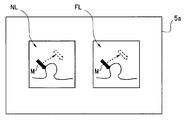
- FIG. 2 is a diagram illustrating a display example of two images.
- FIG. 2 shows two still images that are medical images, that is, a normal light observation image NL and a fluorescence observation image FL, which are displayed side by side on the screen 5a of the monitor 5.
- the control circuit 31 outputs a predetermined control signal to the synthesis circuit 38, and two moving images are displayed on the screen 5 a of the monitor 5.
- the user enlarges and displays the normal light observation image NL by the zoom function before pressing the freeze button 23.
- two still images as shown in FIG. 2 are displayed on the screen 5 a of the monitor 5.
- the user operates the keyboard 6 to display the marker M on the normal light observation image NL, and uses the up / down / left / right arrow keys as shown by dotted lines in FIG.
- the marker M can be positioned at an arbitrary position.
- FIG. 2 shows that the user displays the marker M on the normal light observation image NL, and the marker M is an arrow pointer having an arrow shape and points to a certain point P1 on the image of the living tissue T. Is shown.
- the user can also operate the keyboard 6 to display the marker M on the fluorescence observation image FL.
- the endoscope 2 shown in FIG. 1 uses a lens 14 and a half mirror 16 of a single objective optical system, and the two CCDs 17 and 18 are used for normal light observation images, respectively. This is because a fluorescence observation image is obtained.
- the actuator 21 outputs the terminal position signal, the two observation visual fields of the CCDs 17 and 18 coincide with each other.
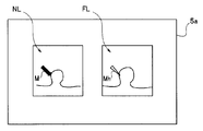
- FIG. 3 is a diagram illustrating a display example of two images when the observation fields of view of the two imaging units are coincident.
- the field of view of the normal light observation image NL and the field of view of the fluorescence observation image FL are the same, when the user operates the keyboard 6 to display the marker M on the normal light observation image NL, for example, the same marker M is displayed. Also displayed on the fluorescence observation image FL.
- the two markers M have the same shape and color, but may be slightly different in color and shape.
- the still images acquired in the CCDs 17 and 18 are images of the same observation field.
- the freeze button 23 when the freeze button 23 is pressed and the actuator 21 outputs the end position signal, the two observation fields of view of the CCDs 17 and 18 coincide with each other.
- the marker M is displayed on one of the images, the same marker M is displayed at the same position on the other image.
- the marker M on the other image moves in the same manner as indicated by a dotted line in FIG.
- the surgeon displays the marker M on one image and the same marker M is also displayed on the other image, the surgeon displays the marker M on the two images. It can be seen that the position indicated by is the same position.
- endoscope 2 is detachably connected to the processor 3 and the light source device 4 as described above, other types of endoscopes can be connected to the processor 3 and the light source device 4. ing.
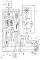
- FIG. 4 is a schematic configuration diagram showing a configuration of an endoscope apparatus 1A in which an endoscope 2A different from the endoscope 2 is connected to a processor 3 and a light source device 4.
- FIG. 4 the same components as those in FIG. In particular, the configurations of the processor 3 and the light source device 4 are the same in FIGS.
- the observation field for the normal light observation image NL may coincide with the observation field for the fluorescence observation image FL.
- the endoscope 2A in FIG. 4 is an endoscope in which the observation field of the normal light observation image NL and the observation field of the fluorescence observation image FL always coincide.
- the endoscope 2A connected to the processor 3 has a lens 14 of one objective optical system and a CCD 17A.
- the processor 3 controls each circuit so that the normal light observation image NL and the fluorescence observation image FL are acquired by the CCD 17A.
- the control circuit 31 can read the identification information in the identification information storage unit 25 of the connected endoscope 2A and determine the type of the connected endoscope 2A. Therefore, the control circuit 31 supplies a control signal corresponding to the determined endoscope type to the timing control circuit 32, and the timing control circuit 32 supplies a timing signal corresponding to the endoscope 2A to the switch 33. To do. In the light source device 4, white light for normal light observation and excitation light for fluorescence observation are alternately output, and in synchronization with the timing, the switch 33 is fluorescence that is return light corresponding to the excitation light. Video signal Ib is selected. That is, the switch 33 intermittently selects and outputs one video signal Ib of the two input signals based on the timing signal from the timing control circuit 32.
- the switch 33 selects the video signal Ib at the same timing as the timing signal that drives the LED 43 and is output to the light source device 4, and freeze memory 34.
- the timing control circuit 32 outputs a timing signal to the switch 33 so as to output to the switch 33.
- the freeze button 23 when the freeze button 23 is pressed, the fluorescence observation image is stored in the freeze memory 34, and the normal light observation image is stored in the freeze memory 35.
- FIG. 5 is a schematic configuration diagram showing a configuration of an endoscope apparatus 1B in which an endoscope 2B different from the endoscope 2 is connected to the processor 3 and the light source device 4.
- FIG. 5 the same components as those in FIG. In particular, the configurations of the processor 3 and the light source device 4 are the same in FIGS. 1 and 5.
- the endoscope 2 shown in FIG. 1 is an endoscope in which the observation visual field for the normal light observation image NL and the observation visual field for the fluorescence observation image FL may coincide with each other depending on the zoom position.
- 2A is an endoscope in which the observation field for the normal light observation image NL always matches the observation field for the fluorescence observation image FL, but the endoscope 2B in FIG. 5 is an observation field for the normal light observation image NL.
- the observation field for the fluorescence observation image FL are endoscopes that do not always coincide.
- an endoscope 2B connected to the processor 3 has two CCDs 17B and 18B that are imaged through different objective optical systems, and the normal light observation image NL is acquired by the CCD 17B.
- the fluorescence observation image FL is acquired by the CCD 18B. Therefore, in the endoscope 2B, the observation field for the normal light observation image NL and the observation field for the fluorescence observation image FL do not always coincide.
- the control circuit 31 can read the identification information in the identification information storage unit 25 of the connected endoscope 2B and determine the type of the connected endoscope 2B. Therefore, the control circuit 31 supplies a control signal corresponding to the determined endoscope type to the timing control circuit 32, and the timing control circuit 32 supplies a timing signal corresponding to the endoscope 2B to the switch 33. To do.
- the switch 33 is fluorescence that is return light corresponding to the excitation light. Select the video signal Ia.
- the switch 33 intermittently selects and outputs one video signal Ia of the two input signals based on the timing signal from the timing control circuit 32.
- the switch 33 selects the video signal Ia and outputs the freeze memory 34 at the same timing as the timing signal for driving the LED 43 output to the light source device 4.
- the timing control circuit 32 outputs a timing signal to the switch 33 so as to output to the switch 33. Therefore, when the freeze button 23 is pressed, the freeze memory 34 stores the fluorescence observation image obtained by imaging with the CCD 18B, and the freeze memory 35 stores the normal light observation image.
- the control circuit 31 reads the identification information in the identification information storage unit 25 of the connected endoscope, and based on the identification information, the two images obtained by the CCDs 17 and 18 are read out. Determine whether the observation fields match or do not match. Therefore, the control circuit 31 configures an observation visual field determination unit that determines the coincidence of the observation visual fields for the two images based on the identification information stored in the identification information storage unit 25.
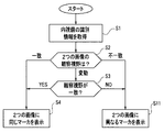
- FIG. 6 is a flowchart illustrating an example of processing of the CPU 31a of the control circuit 31.
- the processing of FIG. 6 is executed. 6 is performed when the CPU 31a reads and executes a software program stored in a storage device such as a ROM (not shown).
- the CPU 31a of the control circuit 31 reads and acquires the identification information in the identification information storage unit 25 of the endoscope connected to the processor 3 (S1). Based on the read identification information, the CPU 31a determines whether the observation visual fields for the two images obtained by the endoscope are always the same, are always inconsistent, or are inconsistent in some cases. Are determined (S2).
- the identification information of the endoscope is information indicating the type of the endoscope, and the endoscope outputs two images whose observation fields always coincide with each other based on the identification information. It is possible to determine whether to output two images that are always inconsistent or to output two images that may match.
- the CPU 31a determines that the connected endoscope is an endoscope that outputs two images in which the observation visual fields may coincide, that is, 2 If it is determined that the endoscope is a endoscope in which at least one of the observation visual fields of one image changes, the process proceeds to S3.
- the connected endoscope is an endoscope 2 as shown in FIG.
- the CPU 31a determines whether or not the observation visual fields match. This determination is made based on the presence / absence of a terminal position signal from the actuator 21. Since the CPU 31a holds or stores the end position signal from the actuator 21 when the freeze button 23 is pressed, the CPU 31a can make the determination of S3.
- the CPU 31a displays the same marker M on both of the two images (S4). As shown in FIG. 3, the user can move the position of the displayed marker M on two images using the up / down / left / right keys of the keyboard 6.
- the CPU 31a displays the marker M on one of the two images (S4).
- the user can move the position of the displayed marker on the image on which the marker M is displayed using the up / down / left / right keys of the keyboard 6.
- the marker M is displayed on the normal light observation image NL.
- the marker M can be displayed on the fluorescence observation image FL by a user instruction.
- the CPU 31a determines that the connected endoscope is an endoscope that outputs two images whose observation visual fields always coincide with each other. If so (S2: match), the process proceeds to S4. In this case, the connected endoscope is an endoscope 2A as shown in FIG. 4, and the observation fields of the two images always coincide with each other. The same marker M is displayed on both (S4).
- the CPU 31a determines that the connected endoscope is an endoscope that outputs two images whose observation visual fields are always inconsistent. In the case (S2: mismatch), the process proceeds to S5. In this case, the connected endoscope is an endoscope 2B as shown in FIG. 5, and the observation field of view of the two images is always inconsistent.
- the marker M is displayed on one side (S5).
- the synthesis circuit 38 displays the same marker M superimposed on each of the two images.
- the marker is superimposed on one of the two images and displayed.
- the same marker M is displayed on the two images, so that a user such as a surgeon has two markers M displayed on the two images. It can be recognized that the same position on the two images is shown.
- the marker M is displayed on only one of the two images, the user can see that the observation fields of view for the two images do not match.
- the same marker M is displayed on the two images when the observation visual fields for the two images match, and one image is displayed when the observation visual fields for the two images do not match.
- the marker M is displayed only on the upper side, and the marker M is not displayed on the other image.
- two markers having different shapes or colors are combined into two images. You may make it display.
- FIG. 7 is a diagram showing a display example of two images on the screen 5a of the monitor 5 when two markers having different forms or colors are displayed on two images.
- the user operates the keyboard 6 to preset whether to display two markers or only one when the observation visual fields for the two images do not match.
- two observation markers are displayed but are selected or set, when the observation visual fields for the two images are not identical, as shown in FIG.
- a marker Mh having a different color and shape from the marker M is displayed on the fluorescence observation image FL.
- an image like FIG. 3 is displayed.
- the marker Mh is different in shape and color from the marker M, but at least one of the shape and color may be different.
- FIG. 8 is a flowchart showing an example of processing of the CPU 31a of the control circuit 31 for displaying the image of FIG.
- the same reference numerals as those in FIG. 8 are identical reference numerals as those in FIG.
- the synthesis circuit 38 displays the same marker superimposed on each of the two images, and the observation visual field determination unit When it is determined that the observation fields of view for the two images are inconsistent, different markers are superimposed and displayed on the two images. Therefore, the user can recognize whether or not the two markers indicate the same position on the two images by the form or color of the marker displayed on the two images.
- a medical device capable of displaying that two markers displayed in two images indicate the same position on the two images, and a marker display control method in a medical image And a medical processor can be provided.
- a medical processor can be provided.
- the surgeon sees and compares the lesion area on two images, if the observation field is found to match, the surgeon can correctly recognize the lesion area. Inspection, treatment, etc. can be performed.
- a zoom function is provided in one of the two imaging units.
- the zoom amount may be detected by the control circuit 31 based on the outputs of the two sensors that detect the outputs of the two actuators, and the coincidence of the visual field ranges for the two images may be determined.
- the above example is an example in which markers are displayed on two still images obtained by freezing using two freeze memories, but two moving images are used using a frame memory for moving images.
- the same marker may be displayed on the two moving images.
Abstract
The processor (3) of an endoscopic apparatus (1), which is a medical instrument: generates two images obtained by imaging returning light, a normal light observation image and a special light observation image; determines the coincidence of the visual fields of the two images; generates a marker (M) representing a position on the living tissue for at least one of the two images based on the results of the determination; displays the two generated images in a single screen on a monitor (5); and displays the generated marker (M) superimposed on at least one of the two images.
Description
本発明は、医療機器、医療画像におけるマーカ表示制御方法及び医療用プロセッサに関し、特に、画像上にマーカを表示することができる医療機器、医療画像におけるマーカ表示制御方法及び医療用プロセッサに関する。
The present invention relates to a medical device, a marker display control method for a medical image, and a medical processor, and more particularly to a medical device that can display a marker on an image, a marker display control method for a medical image, and a medical processor.
従来より、医療画像を表示することのできる医療機器が広く利用されている。例えば、内視鏡装置は、被検体の体腔内に細長の可撓性を有する挿入部を挿入し、挿入部の先端に設けられた撮像素子により撮像して得られた生体組織の画像をモニタ上に表示することができる医療機器である。その医療画像を見て、術者は、観察部位の診断、処置等を行うことができる。
Conventionally, medical devices capable of displaying medical images have been widely used. For example, an endoscope apparatus monitors an image of a living tissue obtained by inserting an elongated flexible insertion portion into a body cavity of a subject and imaging with an imaging element provided at the distal end of the insertion portion. It is a medical device that can be displayed above. By looking at the medical image, the operator can perform diagnosis, treatment, etc. of the observation site.
医療画像をモニタに表示するときに、2つの画像を1つのモニタ上に表示することができる医療機器もある。例えば、内視鏡装置には、同じ被検部位について、通常光観察画像と特殊光観察画像を取得することができるものがある。よって、術者は、モニタ上に通常光観察画像と特殊光観察画像を並べて同時に表示させて、診断、処置等を行うことができる。
Some medical devices can display two images on one monitor when displaying medical images on the monitor. For example, some endoscope apparatuses can acquire a normal light observation image and a special light observation image for the same site to be examined. Therefore, the surgeon can perform diagnosis, treatment, and the like by displaying the normal light observation image and the special light observation image side by side on the monitor and displaying them simultaneously.
また、例えば特開2010-172673号公報に開示されているように、表示された画像上に、マーカを表示させる機能を有する内視鏡装置も提案され、あるいは実用化されている。術者は、マーカにより、画面上の任意の位置を明確に指摘することができる。
Also, as disclosed in, for example, Japanese Patent Application Laid-Open No. 2010-172673, an endoscope apparatus having a function of displaying a marker on a displayed image has been proposed or put into practical use. The surgeon can clearly point out an arbitrary position on the screen using the marker.
しかし、上記の提案に係る内視鏡装置では、通常光観察画像と特殊光観察画像の同時性を保つための工夫はされているが、同時表示された2つの画像上におけるマーカ位置の一致性については考慮されていない。
However, in the endoscope apparatus according to the above proposal, although the device for maintaining the simultaneity of the normal light observation image and the special light observation image is devised, the consistency of the marker positions on the two images displayed simultaneously is consistent. Is not considered.
術者等のユーザは、表示された1つの画像上で所望の位置にマーカを表示させることはできるが、対比すべき2つの画像上にマーカが表示された場合、2つのマーカの示す位置が、2つの画像のそれぞれの生体組織上で一致しているか否かを、ユーザは確認することができなかった。2つの画像の一方はズーム操作により拡大されていたり、あるいは2つの画像が互いに異なる視野を有する2つの撮像部により撮像し得られた画像であったりするので、2つの画像上に表示される2つのマーカが2つの画像上の同じ位置を示しているのかは、モニタを見ているユーザには判らない。
A user such as an operator can display a marker at a desired position on one displayed image. However, when a marker is displayed on two images to be compared, the positions indicated by the two markers are The user has not been able to confirm whether or not the two images match each other on the living tissue. One of the two images is enlarged by a zoom operation, or the two images are images obtained by two imaging units having different fields of view, so that they are displayed on the two images 2 The user looking at the monitor does not know whether the two markers indicate the same position on the two images.
本発明は、このような課題に鑑みてなされたものであり、2つの画像に表示される2つのマーカが2つの画像上の同じ位置を示していることを表示可能な医療機器、医療画像におけるマーカ表示制御方法及び医療用プロセッサを提供することを目的とする。
The present invention has been made in view of such problems, and in medical devices and medical images capable of displaying that two markers displayed on two images indicate the same position on the two images. An object is to provide a marker display control method and a medical processor.
本発明の一態様の医療機器は、生体組織に対して通常光観察用の光と特殊光観察用の光を照射可能な照明部と、前記照明部により前記生体組織に照射された光の戻り光を撮像する撮像部と、前記戻り光を撮像して得られた通常光観察画像と特殊光観察画像の2つの画像を生成する画像処理部と、前記2つの画像についての観察視野の一致を判別する観察視野判別部と、前記観察視野判別部の判別結果に基づいて前記2つの画像のうち少なくとも一方に対して前記生体組織上の位置を示すマーカを生成するマーカ生成部と、前記画像処理部により生成された前記2つの画像を表示装置の一画面内に表示させるとともに、前記2つの画像のうち少なくとも一方に、前記マーカ生成部により生成されたマーカを重畳して表示する表示部と、を備える。
The medical device of one embodiment of the present invention includes a lighting unit that can irradiate a biological tissue with light for normal light observation and light for special light observation, and a return of the light irradiated on the biological tissue by the lighting unit. An image capturing unit that captures light, an image processing unit that generates two images of a normal light observation image and a special light observation image obtained by capturing the return light, and the observation visual field match between the two images An observation visual field discrimination unit for discriminating; a marker generation unit for generating a marker indicating a position on the living tissue for at least one of the two images based on a discrimination result of the observation visual field discrimination unit; and the image processing A display unit that displays the two images generated by the unit on one screen of a display device, and displays the marker generated by the marker generation unit on at least one of the two images. With .
本発明の一態様の医療画像におけるマーカ表示制御方法は、生体組織に対して通常光観察用の光と特殊光観察用の光を照射可能な照明部により前記生体組織に照射された光の戻り光を撮像して得られた通常光観察画像と特殊光観察画像の2つの画像を生成し、前記2つの画像についての観察視野の一致を判別し、前記観察視野の判別結果に基づいて前記2つの画像のうち少なくとも一方に対して前記生体組織上の位置を示すマーカを生成し、生成された前記2つの画像を表示装置の一画面内に表示させるとともに、前記2つの画像のうち少なくとも一方に、前記マーカ生成部により生成されたマーカを重畳して表示する。
The marker display control method in the medical image of one embodiment of the present invention is a return of light irradiated on the living tissue by an illumination unit that can irradiate the living tissue with light for normal light observation and light for special light observation. Two images, a normal light observation image and a special light observation image obtained by imaging light, are generated, the observation visual field coincidence between the two images is determined, and the 2 based on the observation visual field determination result A marker indicating a position on the living tissue is generated for at least one of the two images, the generated two images are displayed on one screen of a display device, and at least one of the two images is displayed. The marker generated by the marker generator is superimposed and displayed.
本発明の一態様の医療用プロセッサは、生体組織に対して通常光観察用の光と特殊光観察用の光を照射可能な照明部により前記生体組織に照射された光の戻り光を撮像する撮像部により撮像された画像を処理する医療用プロセッサであって、前記戻り光を撮像して得られた通常光観察画像と特殊光観察画像の2つの画像を生成する画像処理部と、前記2つの画像についての観察視野の一致を判別する観察視野判別部と、前記観察視野判別部の判別結果に基づいて前記2つの画像のうち少なくとも一方に対して前記生体組織上の位置を示すマーカを生成するマーカ生成部と、前記画像処理部により生成された前記2つの画像を表示装置の一画面内に表示させるとともに、前記2つの画像のうち少なくとも一方に、前記マーカ生成部により生成されたマーカを重畳して表示する表示部と、を備える。
The medical processor of one embodiment of the present invention images the return light of the light irradiated on the living tissue by an illumination unit that can irradiate the living tissue with light for normal light observation and light for special light observation. A medical processor for processing an image picked up by the image pickup unit, the image processing unit for generating two images of a normal light observation image and a special light observation image obtained by imaging the return light; An observation visual field discriminating unit for discriminating coincidence of observation visual fields for two images, and generating a marker indicating a position on the living tissue for at least one of the two images based on a discrimination result of the observation visual field discriminating unit A marker generating unit that performs the display, and the two images generated by the image processing unit are displayed on one screen of the display device, and at least one of the two images is generated by the marker generating unit. And a display unit for displaying and superimposing the marker.
以下、図面を参照して本発明の実施の形態を説明する。
(構成)
図1は、本実施の形態に係わる内視鏡装置の構成を示す模式的な構成図である。医療機器である内視鏡装置1は、内視鏡2とプロセッサ3と光源装置4とを含み、医療用プロセッサであるプロセッサ3には、表示装置であるモニタ5と入力装置であるキーボード6とが接続されている。内視鏡2は、プロセッサ3とはユニバーサルケーブル7により接続されている。さらに、光源装置4は、照明光を供給するように内視鏡2と接続され、制御信号を受信するようにプロセッサ3と接続されている。内視鏡2は、ユニバーサルケーブル7のコネクタ(図示せず)により、プロセッサ3に対して着脱自在に接続されている。 Embodiments of the present invention will be described below with reference to the drawings.
(Constitution)
FIG. 1 is a schematic configuration diagram showing a configuration of an endoscope apparatus according to the present embodiment. An endoscope apparatus 1 that is a medical device includes anendoscope 2, a processor 3, and a light source device 4. The processor 3 that is a medical processor includes a monitor 5 that is a display device, and a keyboard 6 that is an input device. Is connected. The endoscope 2 is connected to the processor 3 by a universal cable 7. Furthermore, the light source device 4 is connected to the endoscope 2 so as to supply illumination light, and is connected to the processor 3 so as to receive a control signal. The endoscope 2 is detachably connected to the processor 3 by a connector (not shown) of a universal cable 7.
(構成)
図1は、本実施の形態に係わる内視鏡装置の構成を示す模式的な構成図である。医療機器である内視鏡装置1は、内視鏡2とプロセッサ3と光源装置4とを含み、医療用プロセッサであるプロセッサ3には、表示装置であるモニタ5と入力装置であるキーボード6とが接続されている。内視鏡2は、プロセッサ3とはユニバーサルケーブル7により接続されている。さらに、光源装置4は、照明光を供給するように内視鏡2と接続され、制御信号を受信するようにプロセッサ3と接続されている。内視鏡2は、ユニバーサルケーブル7のコネクタ(図示せず)により、プロセッサ3に対して着脱自在に接続されている。 Embodiments of the present invention will be described below with reference to the drawings.
(Constitution)
FIG. 1 is a schematic configuration diagram showing a configuration of an endoscope apparatus according to the present embodiment. An endoscope apparatus 1 that is a medical device includes an
内視鏡2は、細長の挿入部11と操作部12とを含む。挿入部11の先端部には、照明用のレンズ13と、対物光学系としてレンズ14とが設けられている。挿入部11には、ライトガイド15が挿通されており、照明用のレンズ13の後ろには、ライトガイド15の先端側の端面が配置されている。ライトガイド15の基端側は、ライトガイド15が光源装置4からの照明光を伝達するように、光源装置4と接続されている。ライトガイド15の基端部には、図示しないコネクタが設けられており、内視鏡2のライトガイド15は、光源装置4に対して着脱自在に接続されている。
The endoscope 2 includes an elongated insertion part 11 and an operation part 12. At the distal end portion of the insertion portion 11, an illumination lens 13 and a lens 14 as an objective optical system are provided. A light guide 15 is inserted through the insertion portion 11, and an end face on the distal end side of the light guide 15 is disposed behind the illumination lens 13. The proximal end side of the light guide 15 is connected to the light source device 4 so that the light guide 15 transmits illumination light from the light source device 4. A connector (not shown) is provided at the base end portion of the light guide 15, and the light guide 15 of the endoscope 2 is detachably connected to the light source device 4.
対物光学系としてのレンズ14の背面には、ハーフミラー16が設けられている。ハーフミラー16は、被検体の生体組織Tからの戻り光を2つの撮像素子17,18に向けるように機能する。
挿入部11の先端部には撮像部が設けられている。撮像部の1つの撮像素子であるCCD17は、通常光観察用の撮像素子であり、ハーフミラー16からの光を、ズームレンズとして機能するレンズ19を通して受光するように配置されている。レンズ19は、レンズ19を支持する支持部材20を介してアクチュエータ21と連結されている。CCD17は、通常光観察用の撮像素子である。すなわち、撮像部は、観察視野範囲を可変させるズームレンズであるレンズ19を有する。 Ahalf mirror 16 is provided on the back surface of the lens 14 as the objective optical system. The half mirror 16 functions to direct return light from the living tissue T of the subject to the two imaging elements 17 and 18.
An imaging unit is provided at the distal end of theinsertion unit 11. The CCD 17 that is one image pickup device of the image pickup unit is an image pickup device for normal light observation, and is arranged so as to receive light from the half mirror 16 through a lens 19 that functions as a zoom lens. The lens 19 is connected to the actuator 21 via a support member 20 that supports the lens 19. The CCD 17 is an image sensor for normal light observation. That is, the imaging unit includes a lens 19 that is a zoom lens that varies the observation visual field range.
挿入部11の先端部には撮像部が設けられている。撮像部の1つの撮像素子であるCCD17は、通常光観察用の撮像素子であり、ハーフミラー16からの光を、ズームレンズとして機能するレンズ19を通して受光するように配置されている。レンズ19は、レンズ19を支持する支持部材20を介してアクチュエータ21と連結されている。CCD17は、通常光観察用の撮像素子である。すなわち、撮像部は、観察視野範囲を可変させるズームレンズであるレンズ19を有する。 A
An imaging unit is provided at the distal end of the
アクチュエータ21は、例えば、特開平09-322566号公報に開示されているような、複数の圧電体層を積層した積層圧電素子と、その積層圧電素子の一部に設けられた積層圧電素子の発生する歪み又は応力を検出する検出部を有するアクチュエータである。アクチュエータ21は、プロセッサ3の制御回路(後述する)からの駆動信号によって駆動される。アクチュエータ21が、レンズ19の光軸に沿って支持部材20を移動させることによって、レンズ19によるズーム機能が達成される。
また、アクチュエータ21は、検出した歪み又は応力から、駆動ストロークの終端に達したことを示す終端位置信号を出力する。アクチュエータ21の出力する終端位置信号は、プロセッサ3へ供給される。アクチュエータ21からこの終端位置信号が出力されているときは、レンズ19が最も広角の時の位置にあることを示している。アクチュエータ21からの終端位置信号は、後述するフリーズボタン23が押下されたときにプロセッサ3において保持される。 Theactuator 21 generates a laminated piezoelectric element in which a plurality of piezoelectric layers are laminated, and a laminated piezoelectric element provided in a part of the laminated piezoelectric element, as disclosed in, for example, Japanese Patent Application Laid-Open No. 09-322566. It is an actuator which has a detection part which detects distortion or stress to perform. The actuator 21 is driven by a drive signal from a control circuit (described later) of the processor 3. The actuator 21 moves the support member 20 along the optical axis of the lens 19, whereby the zoom function by the lens 19 is achieved.
Further, theactuator 21 outputs an end position signal indicating that the end of the drive stroke has been reached from the detected strain or stress. The terminal position signal output from the actuator 21 is supplied to the processor 3. When this terminal position signal is output from the actuator 21, it indicates that the lens 19 is at the widest position. The end position signal from the actuator 21 is held in the processor 3 when a freeze button 23 described later is pressed.
また、アクチュエータ21は、検出した歪み又は応力から、駆動ストロークの終端に達したことを示す終端位置信号を出力する。アクチュエータ21の出力する終端位置信号は、プロセッサ3へ供給される。アクチュエータ21からこの終端位置信号が出力されているときは、レンズ19が最も広角の時の位置にあることを示している。アクチュエータ21からの終端位置信号は、後述するフリーズボタン23が押下されたときにプロセッサ3において保持される。 The
Further, the
なお、図1では、レンズ19が最も広角の時の位置にあることを、アクチュエータ21の終端位置信号に基づいて検出しているが、例えば支持部材20が接触するリミットスイッチにより、レンズ19が最も広角の時の位置にあることを検出するようにしてもよい。
In FIG. 1, it is detected that the lens 19 is in the position at the widest angle based on the end position signal of the actuator 21, but the lens 19 is the most by a limit switch with which the support member 20 contacts, for example. You may make it detect that it exists in the position at the time of a wide angle.
また、撮像部のもう一方の撮像素子であるCCD18は、特殊光観察の一つである蛍光観察のための撮像素子であり、ハーフミラー16からの光を、励起光カットフィルタ22を介して受光するように配置されている。CCD18は、特殊光観察用の撮像素子である。
The CCD 18, which is another imaging element of the imaging unit, is an imaging element for fluorescence observation, which is one of special light observations, and receives light from the half mirror 16 through the excitation light cut filter 22. Are arranged to be. The CCD 18 is an image sensor for special light observation.
よって、内視鏡2は、通常光観察用の光の反射光である戻り光を撮像する撮像部であるCCD17と、特殊光観察用の光の戻り光を撮像する撮像部であるCCD18を有する撮像部を有する。
Therefore, the endoscope 2 includes a CCD 17 that is an imaging unit that captures return light that is reflected light of light for normal light observation, and a CCD 18 that is an imaging unit that captures return light of light for special light observation. It has an imaging part.
CCD17が受光する光は、生体組織Tからの戻り光であり、その戻り光は、通常光観察用の白色光の反射光である。CCD18が受光する光は、生体組織Tからの戻り光であり、その戻り光は、蛍光観察用の励起光により励起された物質の発する蛍光である。すなわち、CCD17と18は、光源装置4からの照明光により生体組織Tに照射された光の戻り光を撮像する撮像部すなわち撮像装置を構成する。
The light received by the CCD 17 is return light from the living tissue T, and the return light is reflected light of white light for normal light observation. The light received by the CCD 18 is return light from the living tissue T, and the return light is fluorescence emitted from a substance excited by excitation light for fluorescence observation. That is, the CCDs 17 and 18 constitute an imaging unit, that is, an imaging device for imaging the return light of the light irradiated on the living tissue T by the illumination light from the light source device 4.
図1では、内視鏡2には蛍光観察用のズーム機能は、設けられていない。CCD18において得られる画像の画角は、CCD17において最も広角時の得られる画像の画角と、同じである。共通の対物光学系であるレンズ14を用いているので、CCD18において得られる画像の画角と、CCD17において最も広角時の得られる画像の画角が同じであるとき、2つの画像についての観察視野は一致する。
In FIG. 1, the endoscope 2 is not provided with a zoom function for fluorescence observation. The angle of view of the image obtained by the CCD 18 is the same as the angle of view of the image obtained by the CCD 17 at the widest angle. Since the lens 14 which is a common objective optical system is used, when the angle of view of the image obtained in the CCD 18 and the angle of view of the image obtained at the widest angle in the CCD 17 are the same, the observation field of view for the two images Match.
アクチュエータ21から出力される終端位置信号は制御回路31に入力される。そして、後述するように、制御回路31は、終端位置信号に基づいて、CCD17と18により得られた2つの画像についての観察視野の一致を判別する。終端位置信号は、ズームレンズであるレンズ19のズーム情報ということができる。よって、制御回路31は、2つの画像についての観察視野の一致を判別する観察視野判別部を構成する。そして、観察視野判別部である制御回路31は、そのズームレンズのズーム情報に基づいて観察視野の一致を判別する。
The terminal position signal output from the actuator 21 is input to the control circuit 31. Then, as will be described later, the control circuit 31 determines the coincidence of the observation visual fields for the two images obtained by the CCDs 17 and 18 based on the end position signal. The end position signal can be said to be zoom information of the lens 19 that is a zoom lens. Therefore, the control circuit 31 constitutes an observation visual field discrimination unit that discriminates the coincidence of the observation visual fields for the two images. Then, the control circuit 31 that is an observation visual field discrimination unit discriminates the coincidence of the observation visual fields based on zoom information of the zoom lens.
操作部12には、術者が操作する各種スイッチが設けられている。図1では、フリーズボタン23とレリーズボタン24が示されている。フリーズボタン23は、静止画を得るためのボタンである。レリーズボタン24は、フリーズして得られた静止画を、図示しない記憶装置に記憶させるためのボタンである。
また、内視鏡2の種類を示す識別情報を格納した識別情報記憶部25が、操作部12に設けられている。 Theoperation unit 12 is provided with various switches operated by the surgeon. In FIG. 1, a freeze button 23 and a release button 24 are shown. The freeze button 23 is a button for obtaining a still image. The release button 24 is a button for storing a still image obtained by freezing in a storage device (not shown).
An identificationinformation storage unit 25 that stores identification information indicating the type of the endoscope 2 is provided in the operation unit 12.
また、内視鏡2の種類を示す識別情報を格納した識別情報記憶部25が、操作部12に設けられている。 The
An identification
プロセッサ3は、制御回路31、タイミング制御回路32、切替器33、フリーズメモリ34,35、マーカ生成及び追加回路36,37、及び合成回路38を含む。
制御回路31は、中央処理装置(以下、CPUという)31aを含み、キーボード6からの操作信号を受信し、受信した操作信号に基づいて各種処理を実行するように、プロセッサ3の全体の制御を行う。制御回路31は、キーボード6に入力された各種コマンドに応じて、ROM(図示せず)に記憶された所定のソフトウエアプログラムを実行することによって、ユーザにより指定された各種処理を実行する制御部である。 Theprocessor 3 includes a control circuit 31, a timing control circuit 32, a switch 33, freeze memories 34 and 35, marker generation and addition circuits 36 and 37, and a synthesis circuit 38.
Thecontrol circuit 31 includes a central processing unit (hereinafter referred to as a CPU) 31a, receives operation signals from the keyboard 6, and controls the entire processor 3 so as to execute various processes based on the received operation signals. Do. The control circuit 31 executes various processes designated by the user by executing predetermined software programs stored in a ROM (not shown) in accordance with various commands input to the keyboard 6. It is.
制御回路31は、中央処理装置(以下、CPUという)31aを含み、キーボード6からの操作信号を受信し、受信した操作信号に基づいて各種処理を実行するように、プロセッサ3の全体の制御を行う。制御回路31は、キーボード6に入力された各種コマンドに応じて、ROM(図示せず)に記憶された所定のソフトウエアプログラムを実行することによって、ユーザにより指定された各種処理を実行する制御部である。 The
The
さらに、制御回路31は、内視鏡2からの各種信号も受信する。具体的には、アクチュエータ21からの終端位置信号、フリーズボタン23及びレリーズボタン24からの各操作信号、識別情報記憶部25からの識別情報を受信する。
Furthermore, the control circuit 31 also receives various signals from the endoscope 2. Specifically, the terminal position signal from the actuator 21, the operation signals from the freeze button 23 and the release button 24, and the identification information from the identification information storage unit 25 are received.
なお、図1では、2つの静止画の同時表示に関係する回路のみを示しており、その他の機能のための回路、例えば、プロセッサ3から供給されるCCD17と18を駆動するための駆動回路及び駆動信号の信号線、は省略している。
Note that FIG. 1 shows only circuits related to the simultaneous display of two still images. Circuits for other functions, for example, drive circuits for driving the CCDs 17 and 18 supplied from the processor 3 and The signal line for the drive signal is omitted.
さらに、制御回路31は、タイミング制御回路32、フリーズメモリ34,35、及びマーカ生成及び追加回路36,37へ制御信号を供給する。制御回路31は、フリーズボタン23の押下によりフリーズ指示を受信すると、フリーズメモリ34,35へ所定の信号を出力する。制御回路31は、キーボード6からマーカの表示指示を受信すると、マーカ生成及び追加回路36,37へ所定の信号を出力する。また、制御回路31は、内視鏡2の識別情報記憶部25の識別情報を読み出して、読み出した識別情報に応じた制御信号をタイミング制御回路32に供給して、内視鏡2の種類に応じた各種タイミング信号をタイミング制御回路32に出力させる。
Furthermore, the control circuit 31 supplies control signals to the timing control circuit 32, the freeze memories 34 and 35, and the marker generation and addition circuits 36 and 37. When receiving the freeze instruction by pressing the freeze button 23, the control circuit 31 outputs a predetermined signal to the freeze memories 34 and 35. When receiving a marker display instruction from the keyboard 6, the control circuit 31 outputs a predetermined signal to the marker generation and addition circuits 36 and 37. Further, the control circuit 31 reads the identification information in the identification information storage unit 25 of the endoscope 2, supplies a control signal corresponding to the read identification information to the timing control circuit 32, and sets the type of the endoscope 2. Various timing signals corresponding thereto are output to the timing control circuit 32.
タイミング制御回路32は、各種モード及び内視鏡2の種類に応じたタイミング信号を各種回路へ供給する。図1では、タイミング制御回路32は、光源装置4と切替器33へタイミング信号を供給している。
The timing control circuit 32 supplies timing signals corresponding to various modes and types of the endoscope 2 to various circuits. In FIG. 1, the timing control circuit 32 supplies a timing signal to the light source device 4 and the switch 33.
切替器33は、2つの映像信号Ia,Ibが入力可能となっており、タイミング制御回路32からのタイミング信号に基づいて、2つの映像信号Ia,Ibの一方を選択して出力する回路である。すなわち、切替器33は、プロセッサ3に接続された内視鏡の種類に応じて、2つの映像信号Ia,Ibの選択を行う。
The switch 33 is a circuit that can input two video signals Ia and Ib, and selects and outputs one of the two video signals Ia and Ib based on the timing signal from the timing control circuit 32. . That is, the switch 33 selects two video signals Ia and Ib according to the type of endoscope connected to the processor 3.
図1では、内視鏡2が接続されているので、切替器33には、2つのCCD17,18からの映像信号Ia,Ibが入力されているが、切替器33は、タイミング制御回路32からのタイミング信号に基づいて、映像信号Iaを常に選択して、フリーズメモリ34へ出力するように制御される。言い換えれば、タイミング制御回路32は、内視鏡2が接続されているときは、映像信号Iaを常に選択して出力するようなタイミング信号を切替器33へ供給する。
In FIG. 1, since the endoscope 2 is connected, the video signals Ia and Ib from the two CCDs 17 and 18 are input to the switch 33, but the switch 33 is connected to the timing control circuit 32. On the basis of the timing signal, the video signal Ia is always selected and controlled to be output to the freeze memory 34. In other words, when the endoscope 2 is connected, the timing control circuit 32 supplies the switch 33 with a timing signal that always selects and outputs the video signal Ia.
フリーズメモリ34は、制御回路31からの制御信号に基づいて、切替器33から出力された映像信号を記憶する静止画用のメモリであり、フリーズメモリ35も、制御回路31からの制御信号に基づいて、CCD17からの映像信号を記憶する静止画用のメモリである。
タイミング制御回路32,切替器33,及びフリーズメモリ34,35が、通常光観察用の光と特殊観察用の光の照射に同期して、戻り光を撮像して得られた通常光観察画像と特殊光観察画像の2つの画像を生成する画像処理部を構成する。 Thefreeze memory 34 is a still image memory that stores the video signal output from the switch 33 based on the control signal from the control circuit 31. The freeze memory 35 is also based on the control signal from the control circuit 31. This is a still image memory for storing the video signal from the CCD 17.
The normal light observation image obtained by imaging the return light in synchronization with the irradiation of the normal light observation light and the special observation light by thetiming control circuit 32, the switch 33, and the freeze memories 34 and 35; An image processing unit that generates two images of the special light observation image is configured.
タイミング制御回路32,切替器33,及びフリーズメモリ34,35が、通常光観察用の光と特殊観察用の光の照射に同期して、戻り光を撮像して得られた通常光観察画像と特殊光観察画像の2つの画像を生成する画像処理部を構成する。 The
The normal light observation image obtained by imaging the return light in synchronization with the irradiation of the normal light observation light and the special observation light by the
マーカ生成及び追加回路36、37は、それぞれフリーズメモリ34,35からの映像信号に、重畳するマーカの画像信号を生成し、映像信号に追加する処理を行い、マーカが追加された各映像信号を合成回路38へ出力する回路である。マーカ生成及び追加回路36、37は、制御回路31からの制御信号に基づいて、入力された映像信号にマーカを追加する。すなわち、マーカ生成及び追加回路36、37は、それぞれ、制御回路31からの制御信号に基づいて、入力された映像信号にマーカを追加する、あるいは追加しない処理を実行する。その結果、マーカ生成及び追加回路36,37は、マーカが追加されたあるいは追加されていない画像を出力する。後述するように、制御回路31とマーカ生成及び追加回路36,37は、観察視野判別部の判別結果に基づいて2つの画像のうち少なくとも一方に対して生体組織上の位置を示すマーカを生成するマーカ生成部を構成する。
The marker generation and addition circuits 36 and 37 generate an image signal of a marker to be superimposed on the video signals from the freeze memories 34 and 35, respectively, and perform processing for adding the image signal to the video signal. This is a circuit for outputting to the synthesis circuit 38. The marker generation and addition circuits 36 and 37 add a marker to the input video signal based on the control signal from the control circuit 31. That is, each of the marker generation and addition circuits 36 and 37 executes processing for adding or not adding a marker to the input video signal based on the control signal from the control circuit 31. As a result, the marker generation and addition circuits 36 and 37 output an image with or without the marker added. As will be described later, the control circuit 31 and the marker generation and addition circuits 36 and 37 generate a marker indicating the position on the living tissue for at least one of the two images based on the determination result of the observation visual field determination unit. A marker generation unit is configured.
なお、図示しないが、制御回路31は、レリーズボタン24の押下によるレリーズ指示を受信すると、フリーズメモリ34,35あるいはマーカ生成及び追加回路36,37の出力信号を、図示しない記憶装置に記憶する処理を実行する。
Although not shown, when the control circuit 31 receives a release instruction when the release button 24 is pressed, the control circuit 31 stores the output signals of the freeze memories 34 and 35 or the marker generation and addition circuits 36 and 37 in a storage device (not shown). Execute.
合成回路38は、マーカ生成及び追加回路36,37から出力された2つの画像を、モニタ5の画面上で並べて同時に表示するように、合成するための回路である。よって、合成回路38からの映像信号を受信するモニタ5の画面上は、通常光観察画像と特殊光観察画像の2つの画像が並べて同時に表示される。ユーザがキーボード6に2つの画像の同時表示を指示するコマンドを入力すると、制御回路31は、2つの画像を同時表示する制御信号を合成回路38へ出力する。
The synthesizing circuit 38 is a circuit for synthesizing the two images output from the marker generating and adding circuits 36 and 37 so that they are displayed side by side on the screen of the monitor 5 at the same time. Therefore, two images of the normal light observation image and the special light observation image are displayed side by side on the screen of the monitor 5 that receives the video signal from the synthesis circuit 38. When the user inputs a command for instructing simultaneous display of two images to the keyboard 6, the control circuit 31 outputs a control signal for simultaneously displaying two images to the synthesis circuit 38.
よって、合成回路38は、画像処理部により生成された2つの画像をモニタ5の一画面である画面5a内に表示させるとともに、2つの画像のうち少なくとも一方に、マーカ生成部により生成されたマーカを重畳して表示する表示部を構成する。
Therefore, the synthesis circuit 38 displays the two images generated by the image processing unit on the screen 5a which is one screen of the monitor 5, and at least one of the two images has the marker generated by the marker generation unit. A display unit that superimposes and displays is configured.
なお、ユーザがキーボード6に2つの画像の同時表示を指示するコマンドを入力していないときは、制御回路31は、2つの画像の一方を表示する制御信号を合成回路38へ出力する。
When the user does not input a command for instructing simultaneous display of two images to the keyboard 6, the control circuit 31 outputs a control signal for displaying one of the two images to the synthesis circuit 38.
光源装置4は、光源制御回路41、発光素子である2つのLED42,43、ハーフミラー44、及び集光レンズ45を含む。
光源制御回路41は、タイミング制御回路32からのタイミング信号に基づいてLED42と43への駆動信号を生成して出力する。
LED42は、通常光観察用の白色光を発する発光素子であり、LED43は、蛍光観察用の所定の波長帯域の励起光を発する発光素子である。内視鏡装置1が、通常光観察画像と蛍光観察画像の両方を出力する動作モードにあるとき、光源制御回路41は、LED42と43へ交互に所定の駆動信号を供給することによって、LED42と43は排他的に交互に駆動される。よって、光源装置4は、生体組織Tに対して通常光観察用の光及び特殊光観察用の光を照射可能な照明部あるいは照明装置を構成する。 Thelight source device 4 includes a light source control circuit 41, two LEDs 42 and 43 that are light emitting elements, a half mirror 44, and a condenser lens 45.
The lightsource control circuit 41 generates and outputs drive signals to the LEDs 42 and 43 based on the timing signal from the timing control circuit 32.
TheLED 42 is a light emitting element that emits white light for normal light observation, and the LED 43 is a light emitting element that emits excitation light in a predetermined wavelength band for fluorescence observation. When the endoscope apparatus 1 is in an operation mode for outputting both a normal light observation image and a fluorescence observation image, the light source control circuit 41 supplies predetermined drive signals to the LEDs 42 and 43 alternately, thereby 43 are driven alternately and exclusively. Therefore, the light source device 4 constitutes an illumination unit or an illumination device that can irradiate the living tissue T with light for normal light observation and light for special light observation.
光源制御回路41は、タイミング制御回路32からのタイミング信号に基づいてLED42と43への駆動信号を生成して出力する。
LED42は、通常光観察用の白色光を発する発光素子であり、LED43は、蛍光観察用の所定の波長帯域の励起光を発する発光素子である。内視鏡装置1が、通常光観察画像と蛍光観察画像の両方を出力する動作モードにあるとき、光源制御回路41は、LED42と43へ交互に所定の駆動信号を供給することによって、LED42と43は排他的に交互に駆動される。よって、光源装置4は、生体組織Tに対して通常光観察用の光及び特殊光観察用の光を照射可能な照明部あるいは照明装置を構成する。 The
The light
The
LED42と43からの照明光は、ハーフミラー44を通って集光レンズ45に向けられ、集光レンズ45は、光源装置4に接続されたライトガイド15の基端側の端面に、照明光を集光する。よって、照明光は、ライトガイド15を通って、ライトガイド15の先端側の端面から出射される。ライトガイド15の先端側の端面から出射された照明光は、照明用のレンズ13を介して、挿入部11の先端部から出射されて観察部位の生体組織Tを照明する。
The illumination light from the LEDs 42 and 43 is directed to the condenser lens 45 through the half mirror 44, and the condenser lens 45 transmits the illumination light to the end face on the proximal end side of the light guide 15 connected to the light source device 4. Condensate. Therefore, the illumination light is emitted from the end surface on the tip side of the light guide 15 through the light guide 15. The illumination light emitted from the end face on the distal end side of the light guide 15 is emitted from the distal end portion of the insertion portion 11 via the illumination lens 13 and illuminates the living tissue T at the observation site.
図2は、2つの画像の表示例を示す図である。図2は、モニタ5の画面5a上に並べて表示された、医療画像である2つの静止画、すなわち通常光観察画像NLと蛍光観察画像FL、を示している。
例えば、ユーザがキーボード6において2つの画像の同時表示のための所定のコマンドを入力すると、制御回路31は、所定の制御信号を合成回路38へ出力し、モニタ5の画面5aに2つの動画像が同時に表示される。図2の例では、ユーザは、フリーズボタン23を押下する前に、ズーム機能により、通常光観察画像NLを拡大表示させている。そして、ユーザが、フリーズボタン23を押下すると、図2に示すような2つの静止画が、モニタ5の画面5a上に表示される。 FIG. 2 is a diagram illustrating a display example of two images. FIG. 2 shows two still images that are medical images, that is, a normal light observation image NL and a fluorescence observation image FL, which are displayed side by side on thescreen 5a of the monitor 5.
For example, when the user inputs a predetermined command for simultaneously displaying two images on the keyboard 6, thecontrol circuit 31 outputs a predetermined control signal to the synthesis circuit 38, and two moving images are displayed on the screen 5 a of the monitor 5. Are displayed at the same time. In the example of FIG. 2, the user enlarges and displays the normal light observation image NL by the zoom function before pressing the freeze button 23. When the user presses the freeze button 23, two still images as shown in FIG. 2 are displayed on the screen 5 a of the monitor 5.
例えば、ユーザがキーボード6において2つの画像の同時表示のための所定のコマンドを入力すると、制御回路31は、所定の制御信号を合成回路38へ出力し、モニタ5の画面5aに2つの動画像が同時に表示される。図2の例では、ユーザは、フリーズボタン23を押下する前に、ズーム機能により、通常光観察画像NLを拡大表示させている。そして、ユーザが、フリーズボタン23を押下すると、図2に示すような2つの静止画が、モニタ5の画面5a上に表示される。 FIG. 2 is a diagram illustrating a display example of two images. FIG. 2 shows two still images that are medical images, that is, a normal light observation image NL and a fluorescence observation image FL, which are displayed side by side on the
For example, when the user inputs a predetermined command for simultaneously displaying two images on the keyboard 6, the
そして、図2に示すように、ユーザは、キーボード6を操作して、マーカMを通常光観察画像NL上に表示させ、かつ上下左右の矢印キーを用いて、図2において点線で示すように、マーカMを任意の位置に位置させることができる。図2は、ユーザがマーカMを通常光観察画像NL上に表示させて、マーカMは、矢印の形状を有するアローポインタであり、生体組織Tの画像上のある点P1を指示していることを示している。なお、ユーザは、キーボード6を操作して、マーカMを蛍光観察画像FL上に表示させることもできる。
Then, as shown in FIG. 2, the user operates the keyboard 6 to display the marker M on the normal light observation image NL, and uses the up / down / left / right arrow keys as shown by dotted lines in FIG. The marker M can be positioned at an arbitrary position. FIG. 2 shows that the user displays the marker M on the normal light observation image NL, and the marker M is an arrow pointer having an arrow shape and points to a certain point P1 on the image of the living tissue T. Is shown. The user can also operate the keyboard 6 to display the marker M on the fluorescence observation image FL.
ユーザが、ズーム機能を操作して、レンズ19を最も広角の位置に移動させて、静止画を取得すると、通常光観察画像NLの視野と蛍光観察画像FLの視野は同一になる。これは、図1に示すように、図1の内視鏡2は、1つのすなわち共通の対物光学系のレンズ14とハーフミラー16を用いて、2つのCCD17と18において、それぞれ通常光観察画像と蛍光観察画像を得ているからである。そして、上述したように、アクチュエータ21が終端位置信号を出力しているときは、CCD17と18の2つの観察視野は、一致する。
When the user operates the zoom function to move the lens 19 to the widest position and acquires a still image, the field of view of the normal light observation image NL and the field of view of the fluorescence observation image FL become the same. As shown in FIG. 1, the endoscope 2 shown in FIG. 1 uses a lens 14 and a half mirror 16 of a single objective optical system, and the two CCDs 17 and 18 are used for normal light observation images, respectively. This is because a fluorescence observation image is obtained. As described above, when the actuator 21 outputs the terminal position signal, the two observation visual fields of the CCDs 17 and 18 coincide with each other.
図3は、2つの撮像部の観察視野が一致しているときの、2つの画像の表示例を示す図である。通常光観察画像NLの視野と蛍光観察画像FLについての観察視野が同一のとき、ユーザがキーボード6を操作して、例えばマーカMを通常光観察画像NL上に表示させた場合、同じマーカMが、蛍光観察画像FL上にも表示される。なお、図3においては、2つのマーカMは、全く形状も色も同一であるが、色や形状を少々変更したものであってもよい。
FIG. 3 is a diagram illustrating a display example of two images when the observation fields of view of the two imaging units are coincident. When the field of view of the normal light observation image NL and the field of view of the fluorescence observation image FL are the same, when the user operates the keyboard 6 to display the marker M on the normal light observation image NL, for example, the same marker M is displayed. Also displayed on the fluorescence observation image FL. In FIG. 3, the two markers M have the same shape and color, but may be slightly different in color and shape.
ユーザが、ズーム機能においてレンズ19を最も広角の位置に移動させた状態でフリーズボタン23を押下すると、CCD17と18において取得されたそれぞれの静止画は、同じ観察視野の画像である。
When the user presses the freeze button 23 with the lens 19 moved to the widest position in the zoom function, the still images acquired in the CCDs 17 and 18 are images of the same observation field.
すなわち、フリーズボタン23が押下されたときに、アクチュエータ21が終端位置信号を出力している場合は、CCD17と18の2つの観察視野は、一致するので、図3に示すように、2つの静止画の一方上にマーカMを表示させたときは、他方の画像上の同じ位置に同じマーカMが表示される。そして、ユーザが、2つの静止画の一方上でマーカMの位置を移動させると、図3において点線で示すように、他方の画像上のマーカMも同様に移動する。
That is, when the freeze button 23 is pressed and the actuator 21 outputs the end position signal, the two observation fields of view of the CCDs 17 and 18 coincide with each other. When the marker M is displayed on one of the images, the same marker M is displayed at the same position on the other image. When the user moves the position of the marker M on one of the two still images, the marker M on the other image moves in the same manner as indicated by a dotted line in FIG.
よって、例えば、術者が、一方の画像上でマーカMを表示させたときに、他方の画像上にも同じマーカMが表示されているときは、術者は、2つの画像上でマーカMにより指示されている位置は、同じ位置であると判る。
Therefore, for example, when the surgeon displays the marker M on one image and the same marker M is also displayed on the other image, the surgeon displays the marker M on the two images. It can be seen that the position indicated by is the same position.
上述したように、内視鏡2は、プロセッサ3及び光源装置4に対して着脱可能に接続されているので、プロセッサ3と光源装置4には、他の種類の内視鏡が接続可能となっている。
Since the endoscope 2 is detachably connected to the processor 3 and the light source device 4 as described above, other types of endoscopes can be connected to the processor 3 and the light source device 4. ing.
図4は、内視鏡2とは異なる内視鏡2Aがプロセッサ3と光源装置4に接続された内視鏡装置1Aの構成を示す模式的構成図である。図4において、図1と同じ構成要素については、同じ符号を付し説明は省略する。特に、プロセッサ3と光源装置4の構成は、図1と図4においては同一である。
FIG. 4 is a schematic configuration diagram showing a configuration of an endoscope apparatus 1A in which an endoscope 2A different from the endoscope 2 is connected to a processor 3 and a light source device 4. In FIG. 4, the same components as those in FIG. In particular, the configurations of the processor 3 and the light source device 4 are the same in FIGS.
図1に示す内視鏡2は、ズーム機能を有するのでズーム位置によっては通常光観察画像NLについての観察視野と蛍光観察画像FLついての観察視野が一致する場合がある内視鏡であるが、図4の内視鏡2Aは、通常光観察画像NLの観察視野と蛍光観察画像FLの観察視野が常に一致する内視鏡である。
Since the endoscope 2 shown in FIG. 1 has a zoom function, depending on the zoom position, the observation field for the normal light observation image NL may coincide with the observation field for the fluorescence observation image FL. The endoscope 2A in FIG. 4 is an endoscope in which the observation field of the normal light observation image NL and the observation field of the fluorescence observation image FL always coincide.
図4に示すように、内視鏡装置1Aにおいて、プロセッサ3に接続された内視鏡2Aは、1つの対物光学系のレンズ14と1つのCCD17Aを有している。プロセッサ3は、CCD17Aにより、通常光観察画像NLと蛍光観察画像FLを取得するように、各回路を制御する。
As shown in FIG. 4, in the endoscope apparatus 1A, the endoscope 2A connected to the processor 3 has a lens 14 of one objective optical system and a CCD 17A. The processor 3 controls each circuit so that the normal light observation image NL and the fluorescence observation image FL are acquired by the CCD 17A.
制御回路31は、接続された内視鏡2Aの識別情報記憶部25の識別情報を読み出し、接続された内視鏡2Aの種類を判別することができる。よって、制御回路31は、判別した内視鏡の種類に応じた制御信号を、タイミング制御回路32へ供給し、タイミング制御回路32は、内視鏡2Aに応じたタイミング信号を切替器33へ供給する。光源装置4では、通常光観察用の白色光と、蛍光観察用の励起光が交互に出力されるので、そのタイミングに同期して、切替器33は、励起光に対応する戻り光である蛍光の映像信号Ibを選択する。すなわち、切替器33は、タイミング制御回路32からのタイミング信号に基づいて、2つの入力信号のうちの一方の映像信号Ibを断続的に選択して出力する。図4に示すように、内視鏡2Aが接続された場合、光源装置4に出力される、LED43を駆動するタイミング信号と同じタイミングで、切替器33が映像信号Ibを選択してフリーズメモリ34へ出力するように、タイミング制御回路32はタイミング信号を切替器33へ出力する。
The control circuit 31 can read the identification information in the identification information storage unit 25 of the connected endoscope 2A and determine the type of the connected endoscope 2A. Therefore, the control circuit 31 supplies a control signal corresponding to the determined endoscope type to the timing control circuit 32, and the timing control circuit 32 supplies a timing signal corresponding to the endoscope 2A to the switch 33. To do. In the light source device 4, white light for normal light observation and excitation light for fluorescence observation are alternately output, and in synchronization with the timing, the switch 33 is fluorescence that is return light corresponding to the excitation light. Video signal Ib is selected. That is, the switch 33 intermittently selects and outputs one video signal Ib of the two input signals based on the timing signal from the timing control circuit 32. As shown in FIG. 4, when the endoscope 2 </ b> A is connected, the switch 33 selects the video signal Ib at the same timing as the timing signal that drives the LED 43 and is output to the light source device 4, and freeze memory 34. The timing control circuit 32 outputs a timing signal to the switch 33 so as to output to the switch 33.
よって、フリーズボタン23が押下されると、フリーズメモリ34には、蛍光観察用画像が記憶され、フリーズメモリ35には、通常光観察用画像が記憶される。
Therefore, when the freeze button 23 is pressed, the fluorescence observation image is stored in the freeze memory 34, and the normal light observation image is stored in the freeze memory 35.
図5は、内視鏡2とは異なる内視鏡2Bがプロセッサ3と光源装置4に接続された内視鏡装置1Bの構成を示す模式的構成図である。図5において、図1と同じ構成要素については、同じ符号を付し説明は省略する。特に、プロセッサ3と光源装置4の構成は、図1と図5においては同一である。
FIG. 5 is a schematic configuration diagram showing a configuration of an endoscope apparatus 1B in which an endoscope 2B different from the endoscope 2 is connected to the processor 3 and the light source device 4. In FIG. 5, the same components as those in FIG. In particular, the configurations of the processor 3 and the light source device 4 are the same in FIGS. 1 and 5.
図1に示す内視鏡2は、ズーム位置によっては通常光観察画像NLについての観察視野と蛍光観察画像FLについての観察視野が一致する場合がある内視鏡であり、図4の内視鏡2Aは、通常光観察画像NLについての観察視野と蛍光観察画像FLについての観察視野が常に一致する内視鏡であるが、図5の内視鏡2Bは、通常光観察画像NLについての観察視野と蛍光観察画像FLについての観察視野が常に一致しない内視鏡である。
The endoscope 2 shown in FIG. 1 is an endoscope in which the observation visual field for the normal light observation image NL and the observation visual field for the fluorescence observation image FL may coincide with each other depending on the zoom position. 2A is an endoscope in which the observation field for the normal light observation image NL always matches the observation field for the fluorescence observation image FL, but the endoscope 2B in FIG. 5 is an observation field for the normal light observation image NL. And the observation field for the fluorescence observation image FL are endoscopes that do not always coincide.
内視鏡装置1Bにおいて、プロセッサ3に接続された内視鏡2Bは、互いに異なる対物光学系を介して撮像される2つのCCD17B、18Bを有し、CCD17Bにより、通常光観察画像NLが取得され、CCD18Bにより、蛍光観察画像FLが取得される。よって、内視鏡2Bでは、通常光観察画像NLについての観察視野と蛍光観察画像FLについての観察視野が常に一致しない。
In the endoscope apparatus 1B, an endoscope 2B connected to the processor 3 has two CCDs 17B and 18B that are imaged through different objective optical systems, and the normal light observation image NL is acquired by the CCD 17B. The fluorescence observation image FL is acquired by the CCD 18B. Therefore, in the endoscope 2B, the observation field for the normal light observation image NL and the observation field for the fluorescence observation image FL do not always coincide.
上述したように、制御回路31は、接続された内視鏡2Bの識別情報記憶部25の識別情報を読み出し、接続された内視鏡2Bの種類を判別することができる。よって、制御回路31は、判別した内視鏡の種類に応じた制御信号を、タイミング制御回路32へ供給し、タイミング制御回路32は、内視鏡2Bに応じたタイミング信号を切替器33へ供給する。光源装置4では、通常光観察用の白色光と、蛍光観察用の励起光が交互に出力されるので、そのタイミングに同期して、切替器33は、励起光に対応する戻り光である蛍光の映像信号Iaを選択する。すなわち、切替器33は、タイミング制御回路32からのタイミング信号に基づいて、2つの入力信号のうちの一方の映像信号Iaを断続的に選択して出力する。図5に示すように、内視鏡2Bが接続された場合、光源装置4に出力される、LED43を駆動するタイミング信号と同じタイミングで、切替器33が映像信号Iaを選択してフリーズメモリ34へ出力するように、タイミング制御回路32はタイミング信号を切替器33へ出力する。
よって、フリーズボタン23が押下されると、フリーズメモリ34には、CCD18Bによって撮像して得られた蛍光観察用画像が記憶され、フリーズメモリ35には、通常光観察用画像が記憶される。 As described above, thecontrol circuit 31 can read the identification information in the identification information storage unit 25 of the connected endoscope 2B and determine the type of the connected endoscope 2B. Therefore, the control circuit 31 supplies a control signal corresponding to the determined endoscope type to the timing control circuit 32, and the timing control circuit 32 supplies a timing signal corresponding to the endoscope 2B to the switch 33. To do. In the light source device 4, white light for normal light observation and excitation light for fluorescence observation are alternately output, and in synchronization with the timing, the switch 33 is fluorescence that is return light corresponding to the excitation light. Select the video signal Ia. That is, the switch 33 intermittently selects and outputs one video signal Ia of the two input signals based on the timing signal from the timing control circuit 32. As shown in FIG. 5, when the endoscope 2B is connected, the switch 33 selects the video signal Ia and outputs the freeze memory 34 at the same timing as the timing signal for driving the LED 43 output to the light source device 4. The timing control circuit 32 outputs a timing signal to the switch 33 so as to output to the switch 33.
Therefore, when thefreeze button 23 is pressed, the freeze memory 34 stores the fluorescence observation image obtained by imaging with the CCD 18B, and the freeze memory 35 stores the normal light observation image.
よって、フリーズボタン23が押下されると、フリーズメモリ34には、CCD18Bによって撮像して得られた蛍光観察用画像が記憶され、フリーズメモリ35には、通常光観察用画像が記憶される。 As described above, the
Therefore, when the
図4と図5の場合、制御回路31が、接続された内視鏡の識別情報記憶部25の識別情報を読み出し、その識別情報に基づいて、CCD17と18により得られた2つの画像についての観察視野の一致あるいは不一致を判別する。よって、制御回路31は、識別情報記憶部25の識別情報に基づいて、2つの画像についての観察視野の一致を判別する観察視野判別部を構成する。
4 and 5, the control circuit 31 reads the identification information in the identification information storage unit 25 of the connected endoscope, and based on the identification information, the two images obtained by the CCDs 17 and 18 are read out. Determine whether the observation fields match or do not match. Therefore, the control circuit 31 configures an observation visual field determination unit that determines the coincidence of the observation visual fields for the two images based on the identification information stored in the identification information storage unit 25.
(作用)
図6は、制御回路31のCPU31aの処理の例を示すフローチャートである。プロセッサ3が動作中に、ユーザによりマーカの表示指示がされると、図6の処理が実行される。なお、図6の処理は、CPU31aが、図示しないROMなどの記憶装置に記憶されたソフトウエアプログラムを読み出して実行することに、行われる。 (Function)
FIG. 6 is a flowchart illustrating an example of processing of theCPU 31a of the control circuit 31. When the user gives a marker display instruction while the processor 3 is operating, the processing of FIG. 6 is executed. 6 is performed when the CPU 31a reads and executes a software program stored in a storage device such as a ROM (not shown).
図6は、制御回路31のCPU31aの処理の例を示すフローチャートである。プロセッサ3が動作中に、ユーザによりマーカの表示指示がされると、図6の処理が実行される。なお、図6の処理は、CPU31aが、図示しないROMなどの記憶装置に記憶されたソフトウエアプログラムを読み出して実行することに、行われる。 (Function)
FIG. 6 is a flowchart illustrating an example of processing of the
制御回路31のCPU31aは、プロセッサ3に接続されている内視鏡の識別情報記憶部25の識別情報を読み出して取得する(S1)。
CPU31aは、読み出した識別情報に基づいて、内視鏡において得られる2つの画像についての観察視野が常に一致しているのか、常に不一致であるのか、あるいは一致する場合のある変動するものであるのか、を判定する(S2)。 TheCPU 31a of the control circuit 31 reads and acquires the identification information in the identification information storage unit 25 of the endoscope connected to the processor 3 (S1).
Based on the read identification information, theCPU 31a determines whether the observation visual fields for the two images obtained by the endoscope are always the same, are always inconsistent, or are inconsistent in some cases. Are determined (S2).
CPU31aは、読み出した識別情報に基づいて、内視鏡において得られる2つの画像についての観察視野が常に一致しているのか、常に不一致であるのか、あるいは一致する場合のある変動するものであるのか、を判定する(S2)。 The
Based on the read identification information, the
上述したように、内視鏡の識別情報は、内視鏡の種類を示す情報であり、その識別情報により、内視鏡は観察視野が常に一致している2つの画像を出力するものであるのか、常に不一致の2つの画像を出力するものであるのか、あるいは一致する場合のある2つの画像を出力するものであるのかを判定することができる。
As described above, the identification information of the endoscope is information indicating the type of the endoscope, and the endoscope outputs two images whose observation fields always coincide with each other based on the identification information. It is possible to determine whether to output two images that are always inconsistent or to output two images that may match.
そして、CPU31aは、その読み出した内視鏡の識別情報に基づいて、接続されている内視鏡が、観察視野の一致する場合のある2つの画像を出力する内視鏡であると、すなわち2つの画像の観察視野の少なくとも一方が変動する内視鏡であると、判定した場合は、処理は、S3へ移行する。この場合は、接続されている内視鏡が、図1に示すような内視鏡2である場合である。
Then, based on the read endoscope identification information, the CPU 31a determines that the connected endoscope is an endoscope that outputs two images in which the observation visual fields may coincide, that is, 2 If it is determined that the endoscope is a endoscope in which at least one of the observation visual fields of one image changes, the process proceeds to S3. In this case, the connected endoscope is an endoscope 2 as shown in FIG.
S3において、CPU31aは、観察視野が一致しているか否かを判定する。この判定は、アクチュエータ21からの終端位置信号の有無により、行われる。CPU31aはフリーズボタン23が押下されたときにアクチュエータ21からの終端位置信号を保持すなわち記憶するので、CPU31aは、S3の判定を行うことができる。
In S3, the CPU 31a determines whether or not the observation visual fields match. This determination is made based on the presence / absence of a terminal position signal from the actuator 21. Since the CPU 31a holds or stores the end position signal from the actuator 21 when the freeze button 23 is pressed, the CPU 31a can make the determination of S3.
2つの画像の観察視野が一致しているとき(S3:YES)、CPU31aは、2つの画像の両方に同じマーカMを表示する(S4)。図3に示すように、ユーザは、表示されているマーカMの位置を、キーボード6の上下左右キーなどを用いて、2つの画像上で移動させることができる。
When the observation visual fields of the two images coincide (S3: YES), the CPU 31a displays the same marker M on both of the two images (S4). As shown in FIG. 3, the user can move the position of the displayed marker M on two images using the up / down / left / right keys of the keyboard 6.
2つの画像の観察視野が一致していないとき(S3:NO)、CPU31aは、2つの画像の一方にマーカMを表示する(S4)。図2に示すように、ユーザは、表示されているマーカの位置をキーボード6の上下左右キーなどを用いて、そのマーカMが表示されている画像上で移動させることができる。なお、図2では、マーカMは、通常光観察画像NL上に表示されているが、ユーザの指示により、蛍光観察画像FL上にマーカMを表示させることもできる。
When the observation visual fields of the two images do not match (S3: NO), the CPU 31a displays the marker M on one of the two images (S4). As shown in FIG. 2, the user can move the position of the displayed marker on the image on which the marker M is displayed using the up / down / left / right keys of the keyboard 6. In FIG. 2, the marker M is displayed on the normal light observation image NL. However, the marker M can be displayed on the fluorescence observation image FL by a user instruction.
また、その読み出した内視鏡の識別情報に基づいて、接続されている内視鏡が観察視野の常に一致している2つの画像を出力するものである内視鏡であると、CPU31aが判定した場合は(S2:一致)、処理は、S4へ移行する。この場合は、接続されている内視鏡が、図4に示すような内視鏡2Aである場合であり、2つの画像の観察視野が常に一致しているので、CPU31aは、2つの画像の両方に同じマーカMを表示する(S4)。
Further, based on the read-out endoscope identification information, the CPU 31a determines that the connected endoscope is an endoscope that outputs two images whose observation visual fields always coincide with each other. If so (S2: match), the process proceeds to S4. In this case, the connected endoscope is an endoscope 2A as shown in FIG. 4, and the observation fields of the two images always coincide with each other. The same marker M is displayed on both (S4).
さらにまた、その読み出した内視鏡の識別情報に基づいて、接続されている内視鏡が観察視野の常に不一致の2つの画像を出力するものである内視鏡であると、CPU31aが判定した場合は(S2:不一致)、処理は、S5へ移行する。この場合は、接続されている内視鏡が、図5に示すような内視鏡2Bである場合であり、2つの画像の観察視野が常に不一致であるので、CPU31aは、2つの画像のうち、一方にマーカMを表示する(S5)。
フリーズ表示の解除あるいはマーカの非表示の指示があったときは、図6の処理は終了する。 Furthermore, based on the read endoscope identification information, theCPU 31a determines that the connected endoscope is an endoscope that outputs two images whose observation visual fields are always inconsistent. In the case (S2: mismatch), the process proceeds to S5. In this case, the connected endoscope is an endoscope 2B as shown in FIG. 5, and the observation field of view of the two images is always inconsistent. The marker M is displayed on one side (S5).
When there is an instruction to cancel the freeze display or to hide the marker, the processing in FIG. 6 ends.
フリーズ表示の解除あるいはマーカの非表示の指示があったときは、図6の処理は終了する。 Furthermore, based on the read endoscope identification information, the
When there is an instruction to cancel the freeze display or to hide the marker, the processing in FIG. 6 ends.
以上のように、合成回路38は、観察視野判別部が2つの画像についての観察視野が一致すると判定したときは、2つの画像のそれぞれ上に同じマーカMを重畳して表示し、観察視野判別部が2つの画像についての観察視野が不一致であると判定したときは、2つの画像の一方上にマーカを重畳して表示する。
As described above, when the observation visual field discriminating unit determines that the observation visual fields for the two images coincide with each other, the synthesis circuit 38 displays the same marker M superimposed on each of the two images. When the unit determines that the observation fields of view for the two images do not match, the marker is superimposed on one of the two images and displayed.
従って、2つの画像の観察視野が一致しているときは、2つの画像上に同じマーカMが表示されているので、術者等のユーザは、2つの画像に表示される2つのマーカMが、2つの画像上の同じ位置を示していることを認識することができる。そして、2つの画像の一方にのみマーカMが表示されている場合は、ユーザは、2つの画像についての観察視野が一致していないことが判る。
Therefore, when the observation fields of view of the two images match, the same marker M is displayed on the two images, so that a user such as a surgeon has two markers M displayed on the two images. It can be recognized that the same position on the two images is shown. When the marker M is displayed on only one of the two images, the user can see that the observation fields of view for the two images do not match.
なお、以上の例では、2つの画像についての観察視野が一致しているときは、2つの画像上に同じマーカMが表示され、2つの画像についての観察視野が不一致のときは、一方の画像上にのみマーカMを表示し、他方の画像上にはマーカMを表示していないが、2つの画像の観察視野が不一致のときは、互いに形態あるいは色が異なる2つのマーカを2つの画像に表示させるようにしてもよい。
In the above example, the same marker M is displayed on the two images when the observation visual fields for the two images match, and one image is displayed when the observation visual fields for the two images do not match. The marker M is displayed only on the upper side, and the marker M is not displayed on the other image. However, if the observation fields of the two images do not match, two markers having different shapes or colors are combined into two images. You may make it display.
図7は、形態あるいは色の少なくとも1つが互いに異なる2つのマーカを2つの画像に表示させるようにした場合のモニタ5の画面5a上の2つの画像の表示例を示す図である。
FIG. 7 is a diagram showing a display example of two images on the screen 5a of the monitor 5 when two markers having different forms or colors are displayed on two images.
ユーザは、キーボード6を操作して、2つの画像についての観察視野が不一致の場合にマーカを2つ表示するか、1つのみ表示するかを、予め設定する。観察視野が不一致の場合にマーカを2つ表示するが選択あるいは設定されている場合、2つの画像についての観察視野が不一致の場合には、図7に示すように、ユーザが通常光観察画像NLでマーカMを表示させたとき、蛍光観察画像FL上には、マーカMとは色と形の異なるマーカMhが表示される。そして、2つの画像についての観察視野が一致している場合は、図3のような画像が表示される。
なお、図7では、マーカMhは、マーカMと形と色が異なっているが、形と色の少なくとも一つを異ならせるようにしてもよい。 The user operates the keyboard 6 to preset whether to display two markers or only one when the observation visual fields for the two images do not match. When two observation markers are displayed but are selected or set, when the observation visual fields for the two images are not identical, as shown in FIG. When the marker M is displayed in the above, a marker Mh having a different color and shape from the marker M is displayed on the fluorescence observation image FL. And when the observation visual field about two images corresponds, an image like FIG. 3 is displayed.
In FIG. 7, the marker Mh is different in shape and color from the marker M, but at least one of the shape and color may be different.
図8は、図7の画像表示をさせるための制御回路31のCPU31aの処理の例を示すフローチャートである。図8において、図6と同じ符号は、同じ処理を示し、説明は省略する。
FIG. 8 is a flowchart showing an example of processing of the CPU 31a of the control circuit 31 for displaying the image of FIG. In FIG. 8, the same reference numerals as those in FIG.
図8において、S2で不一致のとき、及びS3でNOのとき、処理は、S11へ移行する。S11では、CPU31aは、マーカ生成及び追加回路37,38の一方に、他方とは異なるマーカMhを生成させて追加させる指示の制御信号を供給することによって、図7に示すような、2つの画像上に互いに異なるマーカを表示させる。
In FIG. 8, when there is a mismatch at S2, and when NO at S3, the process proceeds to S11. In S11, the CPU 31a supplies a control signal for instructing one of the marker generation and addition circuits 37 and 38 to generate and add a marker Mh different from the other, thereby generating two images as shown in FIG. Different markers are displayed on the top.
以上のように、合成回路38は、観察視野判別部が2つの画像についての観察視野が一致すると判定したときは、2つの画像のそれぞれ上に同じマーカを重畳して表示し、観察視野判別部が2つの画像についての観察視野が不一致であると判定したときは、2つの画像上に互いに異なるマーカを重畳して表示する。
従って、ユーザは、2つの画像上に表示されるマーカの形態あるいは色によって、2つのマーカが2つの画像上の同じ位置を示しているか否かを認識することができる。 As described above, when the observation visual field determination unit determines that the observation visual fields for the two images match, thesynthesis circuit 38 displays the same marker superimposed on each of the two images, and the observation visual field determination unit When it is determined that the observation fields of view for the two images are inconsistent, different markers are superimposed and displayed on the two images.
Therefore, the user can recognize whether or not the two markers indicate the same position on the two images by the form or color of the marker displayed on the two images.
従って、ユーザは、2つの画像上に表示されるマーカの形態あるいは色によって、2つのマーカが2つの画像上の同じ位置を示しているか否かを認識することができる。 As described above, when the observation visual field determination unit determines that the observation visual fields for the two images match, the
Therefore, the user can recognize whether or not the two markers indicate the same position on the two images by the form or color of the marker displayed on the two images.
以上のように、本実施の形態によれば、2つの画像に表示される2つのマーカが2つの画像上の同じ位置を示していることを表示可能な医療機器、医療画像におけるマーカ表示制御方法及び医療用プロセッサを提供することができる。特に、術者は、2つの画像上で病変範囲を見て比較する場合、観察視野が一致していることが判れば、正しく病変範囲を認識することができるので、より容易に、生体組織の検査、処置等を行うことができる。
As described above, according to the present embodiment, a medical device capable of displaying that two markers displayed in two images indicate the same position on the two images, and a marker display control method in a medical image And a medical processor can be provided. In particular, when the surgeon sees and compares the lesion area on two images, if the observation field is found to match, the surgeon can correctly recognize the lesion area. Inspection, treatment, etc. can be performed.
なお、図1において、内視鏡2において、2つの撮像部の一方にズーム機能が設けられているが、2つの撮像部の両方にズーム機能が設けられている場合には、2つのズームのズーム量を、2つのアクチュエータの出力を検出する2つのセンサの出力に基づいて、制御回路31が検出し、2つの画像についての視野範囲の一致を判定するようにしてもよい。
In FIG. 1, in the endoscope 2, a zoom function is provided in one of the two imaging units. However, when both of the two imaging units are provided with a zoom function, The zoom amount may be detected by the control circuit 31 based on the outputs of the two sensors that detect the outputs of the two actuators, and the coincidence of the visual field ranges for the two images may be determined.
さらになお、以上の例では、2つのフリーズメモリを用いて、フリーズして得られた2つの静止画上に、マーカを表示する例であるが、動画用のフレームメモリを用いて、2つの動画像上についての観察視野が一致する場合に、2つの動画像上に同じマーカを表示するようにしてもよい。
Furthermore, the above example is an example in which markers are displayed on two still images obtained by freezing using two freeze memories, but two moving images are used using a frame memory for moving images. When the observation visual fields on the images match, the same marker may be displayed on the two moving images.
本発明は、上述した実施の形態に限定されるものではなく、本発明の要旨を変えない範囲において、種々の変更、改変等が可能である。
The present invention is not limited to the above-described embodiments, and various changes and modifications can be made without departing from the scope of the present invention.
本出願は、2011年5月17日に日本国に出願された特願2011-110728号を優先権主張の基礎として出願するものであり、上記の開示内容は、本願明細書、請求の範囲に引用されるものとする。
This application is filed on the basis of the priority claim of Japanese Patent Application No. 2011-110728 filed in Japan on May 17, 2011. The above disclosure is included in the present specification and claims. Shall be quoted.
Claims (15)
- 生体組織に対して通常光観察用の光と特殊光観察用の光を照射可能な照明部と、
前記照明部により前記生体組織に照射された光の戻り光を撮像する撮像部と、
前記戻り光を撮像して得られた通常光観察画像と特殊光観察画像の2つの画像を生成する画像処理部と、
前記2つの画像についての観察視野の一致を判別する観察視野判別部と、
前記観察視野判別部の判別結果に基づいて前記2つの画像のうち少なくとも一方に対して前記生体組織上の位置を示すマーカを生成するマーカ生成部と、
前記画像処理部により生成された前記2つの画像を表示装置の一画面内に表示させるとともに、前記2つの画像のうち少なくとも一方に、前記マーカ生成部により生成されたマーカを重畳して表示する表示部と、
を備えることを特徴とする医療機器。 An illumination unit capable of irradiating light for normal light observation and light for special light observation on a living tissue;
An imaging unit for imaging the return light of the light irradiated on the living tissue by the illumination unit;
An image processing unit that generates two images of a normal light observation image and a special light observation image obtained by imaging the return light;
An observation visual field discriminating unit for discriminating the coincidence of the observation visual fields for the two images;
A marker generation unit that generates a marker indicating a position on the living tissue with respect to at least one of the two images based on a determination result of the observation visual field determination unit;
Display that displays the two images generated by the image processing unit on one screen of a display device and displays the marker generated by the marker generation unit superimposed on at least one of the two images And
A medical device comprising: - 前記表示部は、前記観察視野判別部が前記2つの画像についての観察視野が一致すると判定したときは、前記2つの画像のそれぞれ上に前記マーカを重畳して表示し、前記観察視野判別部が前記2つの画像についての観察視野が不一致であると判定したときは、前記2つの画像の一方上に前記マーカを重畳して表示することを特徴とする請求項1に記載の医療機器。 The display unit displays the marker superimposed on each of the two images when the observation field determination unit determines that the observation fields for the two images match, and the observation field determination unit 2. The medical device according to claim 1, wherein the marker is superimposed and displayed on one of the two images when it is determined that the observation visual fields of the two images do not coincide with each other.
- 前記表示部は、前記観察視野判別部が前記2つの画像についての観察視野が一致すると判定したときは、前記2つの画像のそれぞれ上に前記マーカを重畳して表示し、前記観察視野判別部が前記2つの画像についての観察視野が不一致であると判定したときは、前記2つの画像上に互いに異なるマーカを重畳して表示することを特徴とする請求項1に記載の医療機器。 The display unit displays the marker superimposed on each of the two images when the observation field determination unit determines that the observation fields for the two images match, and the observation field determination unit 2. The medical device according to claim 1, wherein when it is determined that the observation visual fields of the two images do not coincide with each other, different markers are superimposed on the two images and displayed.
- 前記観察視野判別部は、前記撮像部を有する内視鏡の識別情報に基づいて、前記2つの画像についての前記観察視野の一致を判別することを特徴とする請求項1から3のいずれか1つに記載の医療機器。 The said observation visual field discrimination | determination part discriminate | determines the coincidence of the said observation visual field about the said 2 images based on the identification information of the endoscope which has the said imaging part. Medical device described in one.
- 前記撮像部は、観察視野範囲を可変させるズームレンズを有し、
前記観察視野判別部は、前記ズームレンズのズーム情報に基づいて前記観察視野の一致を判別することを特徴とする請求項1から3のいずれか1つに記載の医療機器。 The imaging unit has a zoom lens that varies the observation visual field range,
The medical device according to any one of claims 1 to 3, wherein the observation visual field determination unit determines whether the observation visual fields coincide with each other based on zoom information of the zoom lens. - さらに、所定のタイミングにおいて前記通常光観察画像と前記特殊光観察画像を保持する観察画像保持部を有し、
前記ズーム情報は、前記通常光観察画像と前記特殊光観察画像が保持される前記所定のタイミングにおける情報であることを特徴とする請求項5に記載の医療機器。 Furthermore, an observation image holding unit that holds the normal light observation image and the special light observation image at a predetermined timing,
6. The medical device according to claim 5, wherein the zoom information is information at the predetermined timing at which the normal light observation image and the special light observation image are held. - 前記撮像部は、観察視野範囲を可変させるズームレンズを有し、
前記観察視野判別部は、前記撮像部を有する内視鏡の識別情報及び前記ズームレンズのズーム情報に基づいて前記観察視野の一致を判別することを特徴とする請求項1から3のいずれか1つに記載の医療機器。 The imaging unit has a zoom lens that varies the observation visual field range,
4. The observation field determination unit according to claim 1, wherein the observation field determination unit determines whether the observation fields coincide with each other based on identification information of an endoscope having the imaging unit and zoom information of the zoom lens. Medical device described in one. - さらに、所定のタイミングにおいて前記通常光観察画像と前記特殊光観察画像を保持する観察画像保持部を有し、
前記ズーム情報は、前記通常光観察画像と前記特殊光観察画像が保持される前記所定のタイミングにおける情報であることを特徴とする請求項7に記載の医療機器。 Furthermore, an observation image holding unit that holds the normal light observation image and the special light observation image at a predetermined timing,
The medical device according to claim 7, wherein the zoom information is information at the predetermined timing at which the normal light observation image and the special light observation image are held. - 前記撮像部は、前記通常光観察用の光の戻り光を撮像する第1の撮像部と前記特殊光観察用の光の戻り光を撮像する第2の撮像部を有することを特徴とする請求項1から3のいずれか1つに記載の医療機器。 The imaging unit includes a first imaging unit that images the return light of the light for normal light observation and a second imaging unit that images the return light of the light for special light observation. Item 4. The medical device according to any one of Items 1 to 3.
- 生体組織に対して通常光観察用の光と特殊光観察用の光を照射可能な照明部により前記生体組織に照射された光の戻り光を撮像して得られた通常光観察画像と特殊光観察画像の2つの画像を生成し、
前記2つの画像についての観察視野の一致を判別し、
前記観察視野の判別結果に基づいて前記2つの画像のうち少なくとも一方に対して前記生体組織上の位置を示すマーカを生成し、
生成された前記2つの画像を表示装置の一画面内に表示させるとともに、前記2つの画像のうち少なくとも一方に、前記マーカ生成部により生成されたマーカを重畳して表示する、
医療画像におけるマーカ表示制御方法。 Normal light observation image and special light obtained by imaging the return light of the light irradiated to the biological tissue by the illumination unit that can irradiate the biological tissue with the light for normal light observation and the light for special light observation Generate two images of the observation image,
Determining the coincidence of the observation field of view for the two images,
Generating a marker indicating a position on the living tissue for at least one of the two images based on the observation visual field discrimination result;
The generated two images are displayed on one screen of a display device, and the marker generated by the marker generation unit is superimposed on and displayed on at least one of the two images.
Marker display control method in medical image. - 前記2つの画像についての前記観察視野が一致すると判別されたときは、前記2つの画像のそれぞれ上に前記マーカを重畳して表示し、前記2つの画像についての前記観察視野が不一致であると判別されたときは、前記2つの画像の一方上に前記マーカを重畳して表示することを特徴とする請求項10に記載の医療画像におけるマーカ表示制御方法。 When it is determined that the observation fields of view for the two images match, the marker is superimposed on each of the two images, and it is determined that the observation fields of view for the two images do not match. The marker display control method for a medical image according to claim 10, wherein the marker is superimposed on one of the two images when displayed.
- 前記2つの画像についての前記観察視野が一致すると判別されたときは、前記2つの画像のそれぞれ上に前記マーカを重畳して表示し、前記2つの画像についての前記観察視野が不一致であると判別されたときは、前記2つの画像上に互いに異なるマーカを重畳して表示することを特徴とする請求項10に記載の医療画像におけるマーカ表示制御方法。 When it is determined that the observation fields of view for the two images match, the marker is superimposed on each of the two images, and it is determined that the observation fields of view for the two images do not match. The marker display control method for a medical image according to claim 10, wherein when it is done, different markers are superimposed and displayed on the two images.
- 前記観察視野の判別は、前記通常光観察画像と前記特殊光観察画像を撮像する撮像部を有する内視鏡の識別情報に基づいて、前記2つの画像についての前記観察視野の一致を判別することを特徴とする請求項10から12のいずれか1つに記載の医療画像におけるマーカ表示制御方法。 The observation visual field is determined by determining the coincidence of the observation visual fields for the two images based on identification information of an endoscope having an imaging unit that captures the normal light observation image and the special light observation image. The marker display control method for medical images according to any one of claims 10 to 12.
- 前記通常光観察画像と前記特殊光観察画像を撮像する撮像部は、観察視野範囲を可変させるズームレンズを有し、
前記観察視野の判別は、前記ズームレンズのズーム情報に基づいて前記観察視野の一致を判別することを特徴とする請求項10から12のいずれか1つに記載の医療画像におけるマーカ表示制御方法。 The imaging unit that captures the normal light observation image and the special light observation image has a zoom lens that varies the observation visual field range,
The marker display control method for a medical image according to any one of claims 10 to 12, wherein the observation visual field is determined by determining coincidence of the observation visual fields based on zoom information of the zoom lens. - 生体組織に対して通常光観察用の光と特殊光観察用の光を照射可能な照明部により前記生体組織に照射された光の戻り光を撮像する撮像部により撮像された画像を処理する医療用プロセッサであって、
前記戻り光を撮像して得られた通常光観察画像と特殊光観察画像の2つの画像を生成する画像処理部と、
前記2つの画像についての観察視野の一致を判別する観察視野判別部と、
前記観察視野判別部の判別結果に基づいて前記2つの画像のうち少なくとも一方に対して前記生体組織上の位置を示すマーカを生成するマーカ生成部と、
前記画像処理部により生成された前記2つの画像を表示装置の一画面内に表示させるとともに、前記2つの画像のうち少なくとも一方に、前記マーカ生成部により生成されたマーカを重畳して表示する表示部と、
を備えることを特徴とする医療用プロセッサ。 Medical that processes an image captured by an imaging unit that captures the return light of the light irradiated to the biological tissue by an illumination unit that can irradiate the biological tissue with light for normal light observation and special light observation Processor for
An image processing unit that generates two images of a normal light observation image and a special light observation image obtained by imaging the return light;
An observation visual field discriminating unit for discriminating the coincidence of the observation visual fields for the two images;
A marker generation unit that generates a marker indicating a position on the living tissue with respect to at least one of the two images based on a determination result of the observation visual field determination unit;
Display that displays the two images generated by the image processing unit on one screen of a display device and displays the marker generated by the marker generation unit superimposed on at least one of the two images And
A medical processor comprising:
Priority Applications (4)
| Application Number | Priority Date | Filing Date | Title |
|---|---|---|---|
| CN201280004932.2A CN103298393B (en) | 2011-05-17 | 2012-03-23 | Labelling display control method in armarium, medical image and medical processor |
| JP2012552203A JP5274724B2 (en) | 2011-05-17 | 2012-03-23 | Medical device, method of operating medical processor and medical processor |
| EP12786034.4A EP2649929B1 (en) | 2011-05-17 | 2012-03-23 | Medical apparatus, method for controlling marker display in a medical image, and medical processor |
| US13/683,584 US8876700B2 (en) | 2011-05-17 | 2012-11-21 | Medical apparatus, method for controlling marker display in medical image and medical processor |
Applications Claiming Priority (2)
| Application Number | Priority Date | Filing Date | Title |
|---|---|---|---|
| JP2011110728 | 2011-05-17 | ||
| JP2011-110728 | 2011-05-17 |
Related Child Applications (1)
| Application Number | Title | Priority Date | Filing Date |
|---|---|---|---|
| US13/683,584 Continuation US8876700B2 (en) | 2011-05-17 | 2012-11-21 | Medical apparatus, method for controlling marker display in medical image and medical processor |
Publications (1)
| Publication Number | Publication Date |
|---|---|
| WO2012157338A1 true WO2012157338A1 (en) | 2012-11-22 |
Family
ID=47176679
Family Applications (1)
| Application Number | Title | Priority Date | Filing Date |
|---|---|---|---|
| PCT/JP2012/057473 WO2012157338A1 (en) | 2011-05-17 | 2012-03-23 | Medical instrument, method for controlling marker display in medical images, and medical processor |
Country Status (5)
| Country | Link |
|---|---|
| US (1) | US8876700B2 (en) |
| EP (1) | EP2649929B1 (en) |
| JP (1) | JP5274724B2 (en) |
| CN (1) | CN103298393B (en) |
| WO (1) | WO2012157338A1 (en) |
Cited By (5)
| Publication number | Priority date | Publication date | Assignee | Title |
|---|---|---|---|---|
| WO2014168128A1 (en) * | 2013-04-12 | 2014-10-16 | オリンパスメディカルシステムズ株式会社 | Endoscope system and operation method for endoscope system |
| CN104582559A (en) * | 2013-03-06 | 2015-04-29 | 奥林巴斯医疗株式会社 | Endoscope system and endoscope system operation method |
| WO2016199273A1 (en) * | 2015-06-11 | 2016-12-15 | オリンパス株式会社 | Endoscope device and operation method for endoscope device |
| JPWO2017038321A1 (en) * | 2015-09-03 | 2018-06-14 | オリンパス株式会社 | Endoscope apparatus and display change control method for endoscope apparatus |
| JPWO2019235195A1 (en) * | 2018-06-04 | 2021-06-03 | 富士フイルム株式会社 | Image processing equipment, endoscopic system, and image processing method |
Families Citing this family (10)
| Publication number | Priority date | Publication date | Assignee | Title |
|---|---|---|---|---|
| JP5155496B2 (en) * | 2010-10-08 | 2013-03-06 | オリンパスメディカルシステムズ株式会社 | Imaging device |
| JP5980604B2 (en) * | 2012-07-18 | 2016-08-31 | オリンパス株式会社 | Endoscope system |
| JP2014128394A (en) * | 2012-12-28 | 2014-07-10 | Hoya Corp | Endoscope device |
| US10405733B2 (en) * | 2015-04-30 | 2019-09-10 | Sony Olympus Medical Solutions Inc. | Medical signal processing device and medical observation system |
| JP6660707B2 (en) * | 2015-10-23 | 2020-03-11 | Hoya株式会社 | Endoscope system |
| US10606149B2 (en) * | 2016-05-25 | 2020-03-31 | Sony Corporation | Information processing device, information processing method, and program |
| JP7073618B2 (en) * | 2016-09-23 | 2022-05-24 | ソニーグループ株式会社 | Control devices, control methods and medical systems |
| WO2019167623A1 (en) * | 2018-03-02 | 2019-09-06 | 富士フイルム株式会社 | Image processing apparatus, endoscope system, and image processing method |
| JP7265823B2 (en) * | 2018-10-19 | 2023-04-27 | キヤノン株式会社 | Imaging device and program |
| CN114343873B (en) * | 2022-01-07 | 2023-04-18 | 苏州康多机器人有限公司 | Endoscope operation monitoring system and method |
Citations (6)
| Publication number | Priority date | Publication date | Assignee | Title |
|---|---|---|---|---|
| JPH0556918A (en) * | 1991-09-05 | 1993-03-09 | Olympus Optical Co Ltd | Endoscope device |
| JPH09322566A (en) | 1996-06-04 | 1997-12-12 | Olympus Optical Co Ltd | Piezoelectric actuator |
| JP2006230906A (en) * | 2005-02-28 | 2006-09-07 | Toshiba Corp | Medical diagnostic system and apparatus, and endoscope |
| JP2007020728A (en) * | 2005-07-13 | 2007-02-01 | Olympus Medical Systems Corp | Image processing device |
| JP2010075368A (en) * | 2008-09-25 | 2010-04-08 | Fujifilm Corp | Apparatus, method, and program of electronic endoscope |
| JP2010172673A (en) | 2009-02-02 | 2010-08-12 | Fujifilm Corp | Endoscope system, processor for endoscope, and endoscopy aiding method |
Family Cites Families (21)
| Publication number | Priority date | Publication date | Assignee | Title |
|---|---|---|---|---|
| US4895431A (en) * | 1986-11-13 | 1990-01-23 | Olympus Optical Co., Ltd. | Method of processing endoscopic images |
| AU617431B2 (en) * | 1988-03-07 | 1991-11-28 | Sharp Kabushiki Kaisha | Interlocked zooming apparatus |
| US5583566A (en) * | 1989-05-12 | 1996-12-10 | Olympus Optical Co., Ltd. | Combined medical image and data transmission with data storage, in which character/diagram information is transmitted with video data |
| JPH04307024A (en) * | 1991-04-02 | 1992-10-29 | Olympus Optical Co Ltd | Electronic endoscope apparatus |
| US5662584A (en) * | 1994-10-07 | 1997-09-02 | Vista Medical Technologies, Inc. | Endoscope with position display for zoom lens unit and imaging device |
| US5672877A (en) * | 1996-03-27 | 1997-09-30 | Adac Laboratories | Coregistration of multi-modality data in a medical imaging system |
| US6404906B2 (en) * | 1997-03-03 | 2002-06-11 | Bacus Research Laboratories,Inc. | Method and apparatus for acquiring and reconstructing magnified specimen images from a computer-controlled microscope |
| US7179222B2 (en) * | 1996-11-20 | 2007-02-20 | Olympus Corporation | Fluorescent endoscope system enabling simultaneous achievement of normal light observation based on reflected light and fluorescence observation based on light with wavelengths in infrared spectrum |
| US6293911B1 (en) * | 1996-11-20 | 2001-09-25 | Olympus Optical Co., Ltd. | Fluorescent endoscope system enabling simultaneous normal light observation and fluorescence observation in infrared spectrum |
| US6322497B1 (en) * | 1998-12-25 | 2001-11-27 | Asahi Kogaku Kogyo Kabushiki Kaisha | Electronic endoscope |
| ATE349944T1 (en) * | 2002-07-31 | 2007-01-15 | Olympus Corp | ENDOSCOPE |
| US7520854B2 (en) * | 2004-07-14 | 2009-04-21 | Olympus Corporation | Endoscope system allowing movement of a display image |
| US20060173358A1 (en) * | 2005-01-11 | 2006-08-03 | Olympus Corporation | Fluorescence observation endoscope apparatus and fluorescence observation method |
| JP2007020727A (en) * | 2005-07-13 | 2007-02-01 | Olympus Medical Systems Corp | Image processing device |
| US20080091065A1 (en) * | 2006-10-04 | 2008-04-17 | Olympus Medical Systems Corporation | Medical image processing apparatus, endoscope system and medical image processing system |
| US8672836B2 (en) * | 2007-01-31 | 2014-03-18 | The Penn State Research Foundation | Method and apparatus for continuous guidance of endoscopy |
| US8270691B2 (en) * | 2007-10-09 | 2012-09-18 | Siemens Aktiengesellschaft | Method for fusing images acquired from a plurality of different image acquiring modalities |
| EP2207056B1 (en) * | 2007-10-30 | 2013-01-09 | Olympus Corporation | Endoscope device |
| US20090213140A1 (en) * | 2008-02-26 | 2009-08-27 | Masaru Ito | Medical support control system |
| US8531479B2 (en) * | 2009-06-12 | 2013-09-10 | Olympus Corporation | Endoscope apparatus and program |
| US20120130171A1 (en) * | 2010-11-18 | 2012-05-24 | C2Cure Inc. | Endoscope guidance based on image matching |
-
2012
- 2012-03-23 WO PCT/JP2012/057473 patent/WO2012157338A1/en active Application Filing
- 2012-03-23 JP JP2012552203A patent/JP5274724B2/en active Active
- 2012-03-23 CN CN201280004932.2A patent/CN103298393B/en active Active
- 2012-03-23 EP EP12786034.4A patent/EP2649929B1/en not_active Not-in-force
- 2012-11-21 US US13/683,584 patent/US8876700B2/en active Active
Patent Citations (6)
| Publication number | Priority date | Publication date | Assignee | Title |
|---|---|---|---|---|
| JPH0556918A (en) * | 1991-09-05 | 1993-03-09 | Olympus Optical Co Ltd | Endoscope device |
| JPH09322566A (en) | 1996-06-04 | 1997-12-12 | Olympus Optical Co Ltd | Piezoelectric actuator |
| JP2006230906A (en) * | 2005-02-28 | 2006-09-07 | Toshiba Corp | Medical diagnostic system and apparatus, and endoscope |
| JP2007020728A (en) * | 2005-07-13 | 2007-02-01 | Olympus Medical Systems Corp | Image processing device |
| JP2010075368A (en) * | 2008-09-25 | 2010-04-08 | Fujifilm Corp | Apparatus, method, and program of electronic endoscope |
| JP2010172673A (en) | 2009-02-02 | 2010-08-12 | Fujifilm Corp | Endoscope system, processor for endoscope, and endoscopy aiding method |
Non-Patent Citations (1)
| Title |
|---|
| See also references of EP2649929A4 |
Cited By (9)
| Publication number | Priority date | Publication date | Assignee | Title |
|---|---|---|---|---|
| CN104582559A (en) * | 2013-03-06 | 2015-04-29 | 奥林巴斯医疗株式会社 | Endoscope system and endoscope system operation method |
| WO2014168128A1 (en) * | 2013-04-12 | 2014-10-16 | オリンパスメディカルシステムズ株式会社 | Endoscope system and operation method for endoscope system |
| CN105050479A (en) * | 2013-04-12 | 2015-11-11 | 奥林巴斯株式会社 | Endoscope system and operation method for endoscope system |
| US9538907B2 (en) | 2013-04-12 | 2017-01-10 | Olympus Corporation | Endoscope system and actuation method for displaying an organ model image pasted with an endoscopic image |
| JPWO2014168128A1 (en) * | 2013-04-12 | 2017-02-16 | オリンパス株式会社 | Endoscope system and method for operating endoscope system |
| WO2016199273A1 (en) * | 2015-06-11 | 2016-12-15 | オリンパス株式会社 | Endoscope device and operation method for endoscope device |
| JPWO2016199273A1 (en) * | 2015-06-11 | 2018-03-29 | オリンパス株式会社 | Endoscope apparatus and method for operating endoscope apparatus |
| JPWO2017038321A1 (en) * | 2015-09-03 | 2018-06-14 | オリンパス株式会社 | Endoscope apparatus and display change control method for endoscope apparatus |
| JPWO2019235195A1 (en) * | 2018-06-04 | 2021-06-03 | 富士フイルム株式会社 | Image processing equipment, endoscopic system, and image processing method |
Also Published As
| Publication number | Publication date |
|---|---|
| JPWO2012157338A1 (en) | 2014-07-31 |
| CN103298393B (en) | 2015-09-16 |
| EP2649929A4 (en) | 2014-03-05 |
| CN103298393A (en) | 2013-09-11 |
| EP2649929A1 (en) | 2013-10-16 |
| JP5274724B2 (en) | 2013-08-28 |
| US8876700B2 (en) | 2014-11-04 |
| EP2649929B1 (en) | 2015-07-01 |
| US20130158352A1 (en) | 2013-06-20 |
Similar Documents
| Publication | Publication Date | Title |
|---|---|---|
| JP5274724B2 (en) | Medical device, method of operating medical processor and medical processor | |
| JP5810248B2 (en) | Endoscope system | |
| KR100954475B1 (en) | Endoscope | |
| JP4856286B2 (en) | Endoscope system | |
| CN113395928A (en) | Enhanced medical vision system and method | |
| JP6001219B1 (en) | Endoscope system | |
| JPWO2018168261A1 (en) | CONTROL DEVICE, CONTROL METHOD, AND PROGRAM | |
| US20070013771A1 (en) | Image processing device | |
| JPWO2019239942A1 (en) | Surgical observation device, surgical observation method, surgical light source device, and surgical light irradiation method | |
| JP5675496B2 (en) | Medical device and medical processor | |
| WO2020008920A1 (en) | Medical observation system, medical observation device, and medical observation device driving method | |
| JP2007236598A (en) | Processor and electronic endoscope system | |
| US20200345215A1 (en) | An imaging device, method and program for producing images of a scene | |
| WO2018180068A1 (en) | Medical imaging device and endoscope | |
| JP2021097720A (en) | Endoscope and arm system | |
| WO2020203225A1 (en) | Medical system, information processing device, and information processing method | |
| US20220022728A1 (en) | Medical system, information processing device, and information processing method | |
| JP6663692B2 (en) | Image processing apparatus, endoscope system, and control method for image processing apparatus | |
| WO2018043205A1 (en) | Medical image processing device, medical image processing method, and program | |
| WO2020203034A1 (en) | Endoscopic system | |
| WO2018220930A1 (en) | Image processing device | |
| WO2022113811A1 (en) | Surgery system, surgery control device, control method, and program | |
| WO2022201933A1 (en) | Intravital observation system, observation system, intravital observation method, and intravital observation device | |
| JP2017086549A (en) | Scanning endoscope apparatus | |
| JP2001109445A (en) | Face-mounted video display device |
Legal Events
| Date | Code | Title | Description |
|---|---|---|---|
| ENP | Entry into the national phase |
Ref document number: 2012552203 Country of ref document: JP Kind code of ref document: A |
|
| 121 | Ep: the epo has been informed by wipo that ep was designated in this application |
Ref document number: 12786034 Country of ref document: EP Kind code of ref document: A1 |
|
| WWE | Wipo information: entry into national phase |
Ref document number: 2012786034 Country of ref document: EP |
|
| NENP | Non-entry into the national phase |
Ref country code: DE |