WO2020008920A1 - Medical observation system, medical observation device, and medical observation device driving method - Google Patents
Medical observation system, medical observation device, and medical observation device driving method Download PDFInfo
- Publication number
- WO2020008920A1 WO2020008920A1 PCT/JP2019/024775 JP2019024775W WO2020008920A1 WO 2020008920 A1 WO2020008920 A1 WO 2020008920A1 JP 2019024775 W JP2019024775 W JP 2019024775W WO 2020008920 A1 WO2020008920 A1 WO 2020008920A1
- Authority
- WO
- WIPO (PCT)
- Prior art keywords
- image
- light
- unit
- speckle contrast
- observation
- Prior art date
Links
- 238000000034 method Methods 0.000 title claims abstract description 107
- 230000010287 polarization Effects 0.000 claims abstract description 182
- 238000012545 processing Methods 0.000 claims abstract description 114
- 230000003287 optical effect Effects 0.000 claims abstract description 85
- 238000004364 calculation method Methods 0.000 claims abstract description 81
- 238000001514 detection method Methods 0.000 claims abstract description 75
- 230000008569 process Effects 0.000 claims abstract description 48
- 238000000926 separation method Methods 0.000 claims abstract description 14
- 238000003384 imaging method Methods 0.000 claims description 158
- 230000017531 blood circulation Effects 0.000 claims description 29
- 210000004204 blood vessel Anatomy 0.000 claims description 20
- 238000004891 communication Methods 0.000 description 46
- 238000010586 diagram Methods 0.000 description 31
- 230000033001 locomotion Effects 0.000 description 31
- 238000012986 modification Methods 0.000 description 30
- 230000004048 modification Effects 0.000 description 30
- 238000004458 analytical method Methods 0.000 description 19
- 230000008859 change Effects 0.000 description 19
- 230000006870 function Effects 0.000 description 19
- 230000010365 information processing Effects 0.000 description 18
- 238000011282 treatment Methods 0.000 description 16
- 229920006395 saturated elastomer Polymers 0.000 description 15
- 238000005516 engineering process Methods 0.000 description 12
- 230000005540 biological transmission Effects 0.000 description 10
- 238000002674 endoscopic surgery Methods 0.000 description 10
- 230000000694 effects Effects 0.000 description 9
- 238000001356 surgical procedure Methods 0.000 description 9
- 210000001519 tissue Anatomy 0.000 description 9
- 239000008280 blood Substances 0.000 description 7
- 210000004369 blood Anatomy 0.000 description 7
- 238000010336 energy treatment Methods 0.000 description 7
- 239000007788 liquid Substances 0.000 description 7
- 238000012935 Averaging Methods 0.000 description 6
- 238000006243 chemical reaction Methods 0.000 description 6
- 239000003795 chemical substances by application Substances 0.000 description 6
- 206010002329 Aneurysm Diseases 0.000 description 5
- 238000004590 computer program Methods 0.000 description 5
- MOFVSTNWEDAEEK-UHFFFAOYSA-M indocyanine green Chemical compound [Na+].[O-]S(=O)(=O)CCCCN1C2=CC=C3C=CC=CC3=C2C(C)(C)C1=CC=CC=CC=CC1=[N+](CCCCS([O-])(=O)=O)C2=CC=C(C=CC=C3)C3=C2C1(C)C MOFVSTNWEDAEEK-UHFFFAOYSA-M 0.000 description 5
- 229960004657 indocyanine green Drugs 0.000 description 5
- 210000004556 brain Anatomy 0.000 description 4
- 238000011156 evaluation Methods 0.000 description 4
- 230000005284 excitation Effects 0.000 description 4
- 238000000605 extraction Methods 0.000 description 4
- 230000001678 irradiating effect Effects 0.000 description 4
- 239000004065 semiconductor Substances 0.000 description 4
- 230000035945 sensitivity Effects 0.000 description 4
- 201000008450 Intracranial aneurysm Diseases 0.000 description 3
- 239000003153 chemical reaction reagent Substances 0.000 description 3
- 238000011161 development Methods 0.000 description 3
- 238000009792 diffusion process Methods 0.000 description 3
- 238000010191 image analysis Methods 0.000 description 3
- OAICVXFJPJFONN-UHFFFAOYSA-N Phosphorus Chemical compound [P] OAICVXFJPJFONN-UHFFFAOYSA-N 0.000 description 2
- 210000003815 abdominal wall Anatomy 0.000 description 2
- 210000001367 artery Anatomy 0.000 description 2
- QVGXLLKOCUKJST-UHFFFAOYSA-N atomic oxygen Chemical compound [O] QVGXLLKOCUKJST-UHFFFAOYSA-N 0.000 description 2
- 230000000740 bleeding effect Effects 0.000 description 2
- 238000002073 fluorescence micrograph Methods 0.000 description 2
- 238000005259 measurement Methods 0.000 description 2
- 235000015097 nutrients Nutrition 0.000 description 2
- 239000013307 optical fiber Substances 0.000 description 2
- 230000001151 other effect Effects 0.000 description 2
- 239000001301 oxygen Substances 0.000 description 2
- 229910052760 oxygen Inorganic materials 0.000 description 2
- 238000007789 sealing Methods 0.000 description 2
- 239000013589 supplement Substances 0.000 description 2
- 230000002194 synthesizing effect Effects 0.000 description 2
- 238000012731 temporal analysis Methods 0.000 description 2
- 125000002066 L-histidyl group Chemical group [H]N1C([H])=NC(C([H])([H])[C@](C(=O)[*])([H])N([H])[H])=C1[H] 0.000 description 1
- FAPWRFPIFSIZLT-UHFFFAOYSA-M Sodium chloride Chemical compound [Na+].[Cl-] FAPWRFPIFSIZLT-UHFFFAOYSA-M 0.000 description 1
- 210000001015 abdomen Anatomy 0.000 description 1
- 230000015572 biosynthetic process Effects 0.000 description 1
- 230000000295 complement effect Effects 0.000 description 1
- 239000002131 composite material Substances 0.000 description 1
- 238000012937 correction Methods 0.000 description 1
- 239000013078 crystal Substances 0.000 description 1
- 238000013500 data storage Methods 0.000 description 1
- 230000006735 deficit Effects 0.000 description 1
- 238000001035 drying Methods 0.000 description 1
- 238000004299 exfoliation Methods 0.000 description 1
- 239000007789 gas Substances 0.000 description 1
- 238000007689 inspection Methods 0.000 description 1
- 230000031700 light absorption Effects 0.000 description 1
- 239000004973 liquid crystal related substance Substances 0.000 description 1
- 230000007246 mechanism Effects 0.000 description 1
- 229910044991 metal oxide Inorganic materials 0.000 description 1
- 150000004706 metal oxides Chemical class 0.000 description 1
- 239000003595 mist Substances 0.000 description 1
- 239000000203 mixture Substances 0.000 description 1
- 210000004400 mucous membrane Anatomy 0.000 description 1
- 238000001615 p wave Methods 0.000 description 1
- 230000002093 peripheral effect Effects 0.000 description 1
- 230000003449 preventive effect Effects 0.000 description 1
- 230000009467 reduction Effects 0.000 description 1
- 239000011780 sodium chloride Substances 0.000 description 1
- 230000005236 sound signal Effects 0.000 description 1
- 230000001954 sterilising effect Effects 0.000 description 1
- 238000004659 sterilization and disinfection Methods 0.000 description 1
- 238000003786 synthesis reaction Methods 0.000 description 1
- 230000000007 visual effect Effects 0.000 description 1
Images


Classifications
-
- A—HUMAN NECESSITIES
- A61—MEDICAL OR VETERINARY SCIENCE; HYGIENE
- A61B—DIAGNOSIS; SURGERY; IDENTIFICATION
- A61B1/00—Instruments for performing medical examinations of the interior of cavities or tubes of the body by visual or photographical inspection, e.g. endoscopes; Illuminating arrangements therefor
- A61B1/06—Instruments for performing medical examinations of the interior of cavities or tubes of the body by visual or photographical inspection, e.g. endoscopes; Illuminating arrangements therefor with illuminating arrangements
- A61B1/063—Instruments for performing medical examinations of the interior of cavities or tubes of the body by visual or photographical inspection, e.g. endoscopes; Illuminating arrangements therefor with illuminating arrangements for monochromatic or narrow-band illumination
-
- A—HUMAN NECESSITIES
- A61—MEDICAL OR VETERINARY SCIENCE; HYGIENE
- A61B—DIAGNOSIS; SURGERY; IDENTIFICATION
- A61B1/00—Instruments for performing medical examinations of the interior of cavities or tubes of the body by visual or photographical inspection, e.g. endoscopes; Illuminating arrangements therefor
- A61B1/00002—Operational features of endoscopes
- A61B1/00004—Operational features of endoscopes characterised by electronic signal processing
- A61B1/00009—Operational features of endoscopes characterised by electronic signal processing of image signals during a use of endoscope
- A61B1/000095—Operational features of endoscopes characterised by electronic signal processing of image signals during a use of endoscope for image enhancement
-
- A—HUMAN NECESSITIES
- A61—MEDICAL OR VETERINARY SCIENCE; HYGIENE
- A61B—DIAGNOSIS; SURGERY; IDENTIFICATION
- A61B1/00—Instruments for performing medical examinations of the interior of cavities or tubes of the body by visual or photographical inspection, e.g. endoscopes; Illuminating arrangements therefor
- A61B1/00163—Optical arrangements
- A61B1/00186—Optical arrangements with imaging filters
-
- A—HUMAN NECESSITIES
- A61—MEDICAL OR VETERINARY SCIENCE; HYGIENE
- A61B—DIAGNOSIS; SURGERY; IDENTIFICATION
- A61B5/00—Measuring for diagnostic purposes; Identification of persons
- A61B5/02—Detecting, measuring or recording pulse, heart rate, blood pressure or blood flow; Combined pulse/heart-rate/blood pressure determination; Evaluating a cardiovascular condition not otherwise provided for, e.g. using combinations of techniques provided for in this group with electrocardiography or electroauscultation; Heart catheters for measuring blood pressure
- A61B5/026—Measuring blood flow
- A61B5/0261—Measuring blood flow using optical means, e.g. infrared light
-
- G—PHYSICS
- G01—MEASURING; TESTING
- G01N—INVESTIGATING OR ANALYSING MATERIALS BY DETERMINING THEIR CHEMICAL OR PHYSICAL PROPERTIES
- G01N21/00—Investigating or analysing materials by the use of optical means, i.e. using sub-millimetre waves, infrared, visible or ultraviolet light
- G01N21/17—Systems in which incident light is modified in accordance with the properties of the material investigated
-
- G—PHYSICS
- G02—OPTICS
- G02B—OPTICAL ELEMENTS, SYSTEMS OR APPARATUS
- G02B21/00—Microscopes
- G02B21/0004—Microscopes specially adapted for specific applications
- G02B21/0012—Surgical microscopes
-
- G—PHYSICS
- G02—OPTICS
- G02B—OPTICAL ELEMENTS, SYSTEMS OR APPARATUS
- G02B21/00—Microscopes
- G02B21/0004—Microscopes specially adapted for specific applications
- G02B21/0092—Polarisation microscopes
-
- G—PHYSICS
- G02—OPTICS
- G02B—OPTICAL ELEMENTS, SYSTEMS OR APPARATUS
- G02B21/00—Microscopes
- G02B21/18—Arrangements with more than one light path, e.g. for comparing two specimens
-
- G—PHYSICS
- G02—OPTICS
- G02B—OPTICAL ELEMENTS, SYSTEMS OR APPARATUS
- G02B21/00—Microscopes
- G02B21/36—Microscopes arranged for photographic purposes or projection purposes or digital imaging or video purposes including associated control and data processing arrangements
- G02B21/365—Control or image processing arrangements for digital or video microscopes
- G02B21/367—Control or image processing arrangements for digital or video microscopes providing an output produced by processing a plurality of individual source images, e.g. image tiling, montage, composite images, depth sectioning, image comparison
-
- G—PHYSICS
- G02—OPTICS
- G02B—OPTICAL ELEMENTS, SYSTEMS OR APPARATUS
- G02B27/00—Optical systems or apparatus not provided for by any of the groups G02B1/00 - G02B26/00, G02B30/00
- G02B27/10—Beam splitting or combining systems
- G02B27/12—Beam splitting or combining systems operating by refraction only
- G02B27/126—The splitting element being a prism or prismatic array, including systems based on total internal reflection
-
- G—PHYSICS
- G02—OPTICS
- G02B—OPTICAL ELEMENTS, SYSTEMS OR APPARATUS
- G02B27/00—Optical systems or apparatus not provided for by any of the groups G02B1/00 - G02B26/00, G02B30/00
- G02B27/48—Laser speckle optics
-
- G—PHYSICS
- G16—INFORMATION AND COMMUNICATION TECHNOLOGY [ICT] SPECIALLY ADAPTED FOR SPECIFIC APPLICATION FIELDS
- G16H—HEALTHCARE INFORMATICS, i.e. INFORMATION AND COMMUNICATION TECHNOLOGY [ICT] SPECIALLY ADAPTED FOR THE HANDLING OR PROCESSING OF MEDICAL OR HEALTHCARE DATA
- G16H20/00—ICT specially adapted for therapies or health-improving plans, e.g. for handling prescriptions, for steering therapy or for monitoring patient compliance
- G16H20/40—ICT specially adapted for therapies or health-improving plans, e.g. for handling prescriptions, for steering therapy or for monitoring patient compliance relating to mechanical, radiation or invasive therapies, e.g. surgery, laser therapy, dialysis or acupuncture
-
- G—PHYSICS
- G16—INFORMATION AND COMMUNICATION TECHNOLOGY [ICT] SPECIALLY ADAPTED FOR SPECIFIC APPLICATION FIELDS
- G16H—HEALTHCARE INFORMATICS, i.e. INFORMATION AND COMMUNICATION TECHNOLOGY [ICT] SPECIALLY ADAPTED FOR THE HANDLING OR PROCESSING OF MEDICAL OR HEALTHCARE DATA
- G16H30/00—ICT specially adapted for the handling or processing of medical images
- G16H30/20—ICT specially adapted for the handling or processing of medical images for handling medical images, e.g. DICOM, HL7 or PACS
-
- G—PHYSICS
- G16—INFORMATION AND COMMUNICATION TECHNOLOGY [ICT] SPECIALLY ADAPTED FOR SPECIFIC APPLICATION FIELDS
- G16H—HEALTHCARE INFORMATICS, i.e. INFORMATION AND COMMUNICATION TECHNOLOGY [ICT] SPECIALLY ADAPTED FOR THE HANDLING OR PROCESSING OF MEDICAL OR HEALTHCARE DATA
- G16H30/00—ICT specially adapted for the handling or processing of medical images
- G16H30/40—ICT specially adapted for the handling or processing of medical images for processing medical images, e.g. editing
-
- G—PHYSICS
- G16—INFORMATION AND COMMUNICATION TECHNOLOGY [ICT] SPECIALLY ADAPTED FOR SPECIFIC APPLICATION FIELDS
- G16H—HEALTHCARE INFORMATICS, i.e. INFORMATION AND COMMUNICATION TECHNOLOGY [ICT] SPECIALLY ADAPTED FOR THE HANDLING OR PROCESSING OF MEDICAL OR HEALTHCARE DATA
- G16H40/00—ICT specially adapted for the management or administration of healthcare resources or facilities; ICT specially adapted for the management or operation of medical equipment or devices
- G16H40/60—ICT specially adapted for the management or administration of healthcare resources or facilities; ICT specially adapted for the management or operation of medical equipment or devices for the operation of medical equipment or devices
- G16H40/67—ICT specially adapted for the management or administration of healthcare resources or facilities; ICT specially adapted for the management or operation of medical equipment or devices for the operation of medical equipment or devices for remote operation
-
- A—HUMAN NECESSITIES
- A61—MEDICAL OR VETERINARY SCIENCE; HYGIENE
- A61B—DIAGNOSIS; SURGERY; IDENTIFICATION
- A61B1/00—Instruments for performing medical examinations of the interior of cavities or tubes of the body by visual or photographical inspection, e.g. endoscopes; Illuminating arrangements therefor
- A61B1/04—Instruments for performing medical examinations of the interior of cavities or tubes of the body by visual or photographical inspection, e.g. endoscopes; Illuminating arrangements therefor combined with photographic or television appliances
- A61B1/042—Instruments for performing medical examinations of the interior of cavities or tubes of the body by visual or photographical inspection, e.g. endoscopes; Illuminating arrangements therefor combined with photographic or television appliances characterised by a proximal camera, e.g. a CCD camera
-
- A—HUMAN NECESSITIES
- A61—MEDICAL OR VETERINARY SCIENCE; HYGIENE
- A61B—DIAGNOSIS; SURGERY; IDENTIFICATION
- A61B1/00—Instruments for performing medical examinations of the interior of cavities or tubes of the body by visual or photographical inspection, e.g. endoscopes; Illuminating arrangements therefor
- A61B1/04—Instruments for performing medical examinations of the interior of cavities or tubes of the body by visual or photographical inspection, e.g. endoscopes; Illuminating arrangements therefor combined with photographic or television appliances
- A61B1/045—Control thereof
-
- A—HUMAN NECESSITIES
- A61—MEDICAL OR VETERINARY SCIENCE; HYGIENE
- A61B—DIAGNOSIS; SURGERY; IDENTIFICATION
- A61B1/00—Instruments for performing medical examinations of the interior of cavities or tubes of the body by visual or photographical inspection, e.g. endoscopes; Illuminating arrangements therefor
- A61B1/06—Instruments for performing medical examinations of the interior of cavities or tubes of the body by visual or photographical inspection, e.g. endoscopes; Illuminating arrangements therefor with illuminating arrangements
- A61B1/0661—Endoscope light sources
- A61B1/0669—Endoscope light sources at proximal end of an endoscope
-
- A—HUMAN NECESSITIES
- A61—MEDICAL OR VETERINARY SCIENCE; HYGIENE
- A61B—DIAGNOSIS; SURGERY; IDENTIFICATION
- A61B1/00—Instruments for performing medical examinations of the interior of cavities or tubes of the body by visual or photographical inspection, e.g. endoscopes; Illuminating arrangements therefor
- A61B1/06—Instruments for performing medical examinations of the interior of cavities or tubes of the body by visual or photographical inspection, e.g. endoscopes; Illuminating arrangements therefor with illuminating arrangements
- A61B1/0661—Endoscope light sources
- A61B1/0684—Endoscope light sources using light emitting diodes [LED]
Definitions
- the present disclosure relates to a medical observation system, a medical observation device, and a driving method of the medical observation device.
- Patent Literature 1 discloses an example of a technique that enables accurate observation of a moving part such as a blood flow using speckle contrast.
- the movement of the affected part to be observed is slight, it may be difficult to detect the movement.
- the speckle contrast is used for observing the affected part, if the movement of the affected part is slight, the change in the speckle contrast tends to be smaller, and it may be difficult to detect the movement.
- the amount of light that can be collected by the imaging unit or the like to obtain an image of the affected part is limited, so a mechanism that can efficiently use the collected light is used. Desired.
- the present disclosure proposes a technique that makes it possible to observe a moving affected part in a more suitable manner.
- a light source that illuminates an affected part, light from the affected part, a branching optical system that separates polarization directions into a plurality of different polarizations, and a detection unit that individually detects each of the plurality of polarizations, Based on each of the detection results of the plurality of polarizations, an arithmetic unit that individually calculates speckle contrast, and at least one of the calculation results of the speckle contrast corresponding to each of the plurality of polarizations, based on the observation of the diseased part And a processing unit that performs processing.
- a branch optical system that separates light from an affected part into a plurality of polarized lights having different polarization directions, a detection unit that individually detects each of the plurality of polarized lights, and detection of the plurality of polarized lights.
- a calculation unit that individually calculates speckle contrast based on each of the results, and a processing unit that performs processing related to observation of the diseased part based on at least one of the calculation results of the speckle contrast corresponding to each of a plurality of polarizations.
- a medical observation device comprising:
- an arithmetic unit that individually calculates speckle contrast, and corresponds to each of the plurality of polarizations
- a processing unit that executes a process related to the observation of the diseased part based on at least one of the calculation results of the speckle contrast to be performed.
- the computer is separated from the light from the diseased part, based on each of the detection results of a plurality of polarizations different from each other in the polarization direction, to calculate the speckle contrast individually, each of the plurality of polarization Executing a process related to observation of the diseased part based on at least one of the calculation results of the speckle contrast corresponding to the above.
- FIG. 1 is a diagram illustrating an example of a schematic configuration of an endoscopic surgery system to which the technology according to the present disclosure can be applied.
- FIG. 2 is a block diagram illustrating an example of a functional configuration of a camera head and a CCU illustrated in FIG. 1.
- FIG. 3 is an explanatory diagram for describing an overview of speckle contrast.
- FIG. 3 is an explanatory diagram for describing an overview of speckle contrast.
- FIG. 4 is an explanatory diagram for describing an example of a relationship between speckle contrast and movement of an object.
- FIG. 4 is an explanatory diagram for describing an influence on a calculation result of speckle contrast when polarized light is used.
- FIG. 3 is a diagram illustrating an example of images having different levels of speckle contrast.
- FIG. 9 is an explanatory diagram for describing another example of the relationship between the speckle contrast and the motion of an object.
- FIG. 1 is an explanatory diagram for describing a basic idea of a technique relating to observation of an affected part in a medical observation system according to an embodiment of the present disclosure.
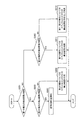
- FIG. 3 is an explanatory diagram for describing an example of the configuration of the medical observation system according to the embodiment; It is a block diagram showing an example of the functional composition of the medical observation system concerning the embodiment. It is a flow chart which showed an example of a flow of a series of processings of a medical observation system concerning the embodiment.
- FIG. 9 is an explanatory diagram for describing an overview of a medical observation system according to a first modification.
- FIG. 1 is an explanatory diagram for describing a basic idea of a technique relating to observation of an affected part in a medical observation system according to an embodiment of the present disclosure.
- FIG. 3 is an explanatory diagram for describing an example of the configuration of the medical observation system
- FIG. 14 is an explanatory diagram for describing an overview of a medical observation system according to a modification 2.
- FIG. 19 is an explanatory diagram for describing an example of a process of the medical observation system according to Modification Example 4.
- 1 is a functional block diagram illustrating a configuration example of a hardware configuration of an information processing device configuring a medical observation system according to an embodiment of the present disclosure.
- FIG. 14 is an explanatory diagram for describing an application example of the medical observation system according to an embodiment of the present disclosure.
- FIG. 1 is a diagram illustrating an example of a schematic configuration of an endoscopic surgery system to which the technology according to the present disclosure can be applied.
- FIG. 1 illustrates a state in which an operator (doctor) 167 performs an operation on a patient 171 on a patient bed 169 using the endoscopic operation system 100.
- the endoscope operation system 100 includes an endoscope 101, other surgical instruments 117, a support arm device 127 for supporting the endoscope 101, and various devices for endoscopic surgery. And a cart 137 on which is mounted.
- trocars 125a to 125d are punctured into the abdominal wall. Then, the lens barrel 103 of the endoscope 101 and other surgical instruments 117 are inserted into the body cavity of the patient 171 from the trocars 125a to 125d.
- an insufflation tube 119, an energy treatment device 121, and forceps 123 are inserted into the body cavity of the patient 171 as other operation tools 117.
- the energy treatment tool 121 is a treatment tool that performs incision and exfoliation of tissue, sealing of blood vessels, and the like by high-frequency current and ultrasonic vibration.
- the illustrated surgical tool 117 is merely an example, and various surgical tools that are generally used in an endoscopic operation, such as a set, a retractor, and the like, may be used as the surgical tool 117.
- the image of the operative site in the body cavity of the patient 171 taken by the endoscope 101 is displayed on the display device 141.
- the operator 167 performs a procedure such as excision of the affected part using the energy treatment tool 121 and the forceps 123 while viewing the image of the operated part displayed on the display device 141 in real time.
- the insufflation tube 119, the energy treatment tool 121, and the forceps 123 are supported by the surgeon 167 or an assistant during the operation.
- the support arm device 127 includes an arm 131 extending from the base 129.
- the arm unit 131 includes joints 133a, 133b, and 133c, and links 135a and 135b, and is driven by the control of the arm control device 145.
- the endoscope 101 is supported by the arm 131, and its position and posture are controlled. Thereby, stable fixing of the position of the endoscope 101 can be realized.
- the endoscope 101 includes a lens barrel 103 in which a region of a predetermined length from the distal end is inserted into a body cavity of the patient 171, and a camera head 105 connected to a proximal end of the lens barrel 103.
- the endoscope 101 is configured as a so-called rigid scope having a hard barrel 103.
- the endoscope 101 is configured as a so-called flexible scope having a flexible barrel 103. Is also good.
- the camera head 105 or the endoscope 101 including the camera head 105 corresponds to an example of a “medical observation device”.
- an opening in which the objective lens is fitted is provided.
- a light source device 143 is connected to the endoscope 101, and light generated by the light source device 143 is guided to a tip of the lens barrel by a light guide extending inside the lens barrel 103, and an objective is provided.
- the light is irradiated toward an observation target (in other words, an imaging target) in the body cavity of the patient 171 via the lens.
- the endoscope 101 may be a direct view, a perspective view, or a side view.
- An optical system and an image sensor are provided inside the camera head 105, and light (observation light) from an observation target is focused on the image sensor by the optical system.
- the observation light is photoelectrically converted by the imaging element, and an electric signal corresponding to the observation light, that is, an image signal corresponding to the observation image is generated.
- the image signal is transmitted to a camera control unit (CCU) 139 as RAW data.
- the camera head 105 has a function of adjusting the magnification and the focal length by appropriately driving the optical system.
- the camera head 105 may be provided with a plurality of image sensors in order to support, for example, stereoscopic viewing (3D display).
- a plurality of relay optical systems are provided inside the lens barrel 103 in order to guide observation light to each of the plurality of imaging elements.
- the CCU 139 is configured by a CPU (Central Processing Unit), a GPU (Graphics Processing Unit), and the like, and controls the operations of the endoscope 101 and the display device 141 as a whole. Specifically, the CCU 139 performs various types of image processing for displaying an image based on the image signal, such as a development process (demosaicing process), on the image signal received from the camera head 105. The CCU 139 provides the image signal subjected to the image processing to the display device 141. In addition, the CCU 139 transmits a control signal to the camera head 105 and controls its driving. The control signal may include information on imaging conditions such as a magnification and a focal length.
- the control signal may include information on imaging conditions such as a magnification and a focal length.
- the display device 141 displays an image based on an image signal on which image processing has been performed by the CCU 139 under the control of the CCU 139.
- the endoscope 101 supports high-resolution imaging such as 4K (3840 horizontal pixels ⁇ 2160 vertical pixels) or 8K (7680 horizontal pixels ⁇ 4320 vertical pixels), and / or 3D display
- high-resolution imaging such as 4K (3840 horizontal pixels ⁇ 2160 vertical pixels) or 8K (7680 horizontal pixels ⁇ 4320 vertical pixels)
- 3D display In the case where the display device 141 is compatible, a display device that can display a high-resolution image and / or a device that can display a 3D image can be used.
- the use of the display device 141 having a size of 55 inches or more can provide a more immersive feeling.
- a plurality of display devices 141 having different resolutions and sizes may be provided depending on the application.
- the light source device 143 includes a light source such as an LED (light emitting diode), for example, and supplies the endoscope 101 with irradiation light when imaging the operation site.
- a light source such as an LED (light emitting diode)
- the arm control device 145 is configured by a processor such as a CPU, for example, and operates according to a predetermined program to control the driving of the arm 131 of the support arm device 127 according to a predetermined control method.
- the input device 147 is an input interface to the endoscopic surgery system 100.
- the user can input various information and input instructions to the endoscopic surgery system 100 via the input device 147.
- the user inputs, via the input device 147, various types of information related to surgery, such as physical information of a patient and information about a surgical procedure.
- the user issues an instruction to drive the arm unit 131 via the input device 147 or an instruction to change imaging conditions (such as the type of irradiation light, magnification, and focal length) of the endoscope 101.
- An instruction to drive the energy treatment tool 121 is input.
- the type of the input device 147 is not limited, and the input device 147 may be various known input devices.
- the input device 147 for example, a mouse, a keyboard, a touch panel, a switch, a foot switch 157, and / or a lever can be applied.
- the touch panel may be provided on the display surface of the display device 141.
- the input device 147 is a device worn by a user, such as a glasses-type wearable device or an HMD (Head Mounted Display), and various inputs are performed according to a user's gesture or line of sight detected by these devices. Is performed. Further, the input device 147 includes a camera capable of detecting the movement of the user, and various inputs are performed in accordance with the user's gestures and eyes, which are detected from the video captured by the camera. Further, the input device 147 includes a microphone capable of collecting a user's voice, and various inputs are performed by voice via the microphone.
- a glasses-type wearable device or an HMD Head Mounted Display
- the input device 147 is configured to be capable of inputting various kinds of information in a non-contact manner, a user (for example, an operator 167) belonging to a clean area can operate a device belonging to a dirty area in a non-contact manner. Becomes possible. In addition, since the user can operate the device without releasing his / her hand from the surgical tool, the convenience for the user is improved.
- the treatment instrument control device 149 controls the driving of the energy treatment instrument 121 for cauterizing, incising a tissue, or sealing a blood vessel.
- the insufflation device 151 supplies gas through the insufflation tube 119 through the insufflation tube 119 to inflate the body cavity of the patient 171 for the purpose of securing the visual field by the endoscope 101 and securing the working space of the operator.
- the recorder 153 is a device that can record various types of information related to surgery.
- the printer 155 is a device that can print various types of information related to surgery in various formats such as text, images, and graphs.
- the support arm device 127 includes a base 129 as a base, and an arm 131 extending from the base 129.
- the arm unit 131 includes a plurality of joints 133a, 133b, and 133c, and a plurality of links 135a and 135b connected by the joints 133b.
- FIG. The configuration of the arm section 131 is simplified. Actually, the shapes, numbers and arrangements of the joints 133a to 133c and the links 135a and 135b, the directions of the rotation axes of the joints 133a to 133c, and the like are appropriately set so that the arm 131 has a desired degree of freedom. obtain.
- the arm part 131 can be preferably configured to have six or more degrees of freedom. Accordingly, the endoscope 101 can be freely moved within the movable range of the arm 131, so that the lens barrel 103 of the endoscope 101 can be inserted into the body cavity of the patient 171 from a desired direction. Will be possible.
- the joints 133a to 133c are provided with actuators, and the joints 133a to 133c are configured to be rotatable around a predetermined rotation axis by driving the actuators.
- the drive of the actuator is controlled by the arm control device 145
- the rotation angles of the joints 133a to 133c are controlled, and the drive of the arm 131 is controlled.
- the arm control device 145 can control the driving of the arm unit 131 by various known control methods such as force control or position control.
- the drive of the arm unit 131 is appropriately controlled by the arm control device 145 in accordance with the operation input.
- the position and orientation of the endoscope 101 may be controlled. With this control, after the endoscope 101 at the tip of the arm 131 is moved from an arbitrary position to an arbitrary position, it can be fixedly supported at the position after the movement.
- the arm 131 may be operated by a so-called master slave method. In this case, the arm 131 can be remotely controlled by the user via the input device 147 installed at a location away from the operating room.
- the arm control device 145 When force control is applied, the arm control device 145 receives the external force from the user, and controls the actuators of the joints 133a to 133c so that the arm 131 moves smoothly in accordance with the external force. Driving, so-called power assist control, may be performed.
- the arm 131 when the user moves the arm 131 while directly touching the arm 131, the arm 131 can be moved with a relatively light force. Therefore, the endoscope 101 can be moved more intuitively and with a simpler operation, and the convenience for the user can be improved.
- the endoscope 101 is supported by a doctor called a scopist.
- the position of the endoscope 101 can be fixed more reliably without manual operation, so that an image of the operation site can be stably obtained.
- the operation can be performed smoothly.
- the arm control device 145 is not necessarily provided in the cart 137. Further, the arm control device 145 need not necessarily be one device. For example, the arm control device 145 may be provided in each of the joint portions 133a to 133c of the arm portion 131 of the support arm device 127, and the plurality of arm control devices 145 cooperate with each other to drive the arm portion 131. Control may be realized.
- the light source device 143 supplies the endoscope 101 with irradiation light when capturing an image of an operation part.
- the light source device 143 includes, for example, a white light source including an LED, a laser light source, or a combination thereof.
- a white light source including an LED, a laser light source, or a combination thereof.
- the output intensity and output timing of each color can be controlled with high accuracy. Can be adjusted.
- the laser light from each of the RGB laser light sources is irradiated to the observation target in a time-division manner, and the driving of the image pickup device of the camera head 105 is controlled in synchronization with the irradiation timing, so that each of the RGB laser light sources is controlled. It is also possible to capture the image obtained in a time sharing manner. According to this method, a color image can be obtained without providing a color filter in the image sensor.
- the driving of the light source device 143 may be controlled so as to change the intensity of the output light every predetermined time.
- the driving of the image pickup device of the camera head 105 in synchronization with the timing of the change of the light intensity, an image is acquired in a time-division manner, and the image is synthesized, so that a high dynamic image without a so-called blackout or overexposure is obtained. An image of the range can be generated.
- the light source device 143 may be configured to be able to supply light in a predetermined wavelength band corresponding to special light observation.
- special light observation for example, by utilizing the wavelength dependence of light absorption in body tissue, by irradiating light in a narrower band compared to irradiation light (ie, white light) during normal observation, the surface of the mucous membrane is exposed.
- a so-called narrow-band light observation (Narrow Band Imaging) for photographing a predetermined tissue such as a blood vessel with high contrast is performed.
- a fluorescence observation for obtaining an image by fluorescence generated by irradiating the excitation light may be performed.
- a body tissue is irradiated with excitation light to observe fluorescence from the body tissue (autofluorescence observation), or a reagent such as indocyanine green (ICG) is locally injected into the body tissue and the body tissue is irradiated with the reagent. Irradiation with excitation light corresponding to the fluorescence wavelength of the reagent to obtain a fluorescence image may be performed.
- the light source device 143 can be configured to be able to supply narrowband light and / or excitation light corresponding to such special light observation.
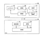
- FIG. 2 is a block diagram illustrating an example of a functional configuration of the camera head 105 and the CCU 139 illustrated in FIG.
- the camera head 105 has, as its functions, a lens unit 107, an imaging unit 109, a driving unit 111, a communication unit 113, and a camera head control unit 115.
- the CCU 139 has a communication unit 159, an image processing unit 161, and a control unit 163 as its functions.
- the camera head 105 and the CCU 139 are communicably connected by a transmission cable 165.
- the lens unit 107 is an optical system provided at a connection with the lens barrel 103. Observation light taken in from the tip of the lens barrel 103 is guided to the camera head 105 and enters the lens unit 107.
- the lens unit 107 is configured by combining a plurality of lenses including a zoom lens and a focus lens. The optical characteristics of the lens unit 107 are adjusted so that the observation light is focused on the light receiving surface of the imaging element of the imaging unit 109. Further, the zoom lens and the focus lens are configured such that their positions on the optical axis are movable for adjusting the magnification and the focus of the captured image.
- the imaging unit 109 is configured by an imaging element, and is arranged at a stage subsequent to the lens unit 107.
- the observation light that has passed through the lens unit 107 is collected on the light receiving surface of the image sensor, and an image signal corresponding to the observation image is generated by photoelectric conversion.
- the image signal generated by the imaging unit 109 is provided to the communication unit 113.
- the imaging device constituting the imaging unit 109 for example, a CMOS (Complementary Metal Oxide Semiconductor) type image sensor which has a Bayer array and can perform color imaging is used.
- CMOS Complementary Metal Oxide Semiconductor
- an image pickup device capable of capturing a high-resolution image of, for example, 4K or more may be used.
- the imaging device constituting the imaging unit 109 is configured to have a pair of imaging devices for acquiring right-eye and left-eye image signals corresponding to 3D display. By performing the 3D display, the operator 167 can more accurately grasp the depth of the living tissue in the operative part.
- the image pickup unit 109 is configured as a multi-plate type, a plurality of lens units 107 are provided corresponding to the respective image pickup devices.
- the imaging unit 109 does not necessarily need to be provided in the camera head 105.
- the imaging unit 109 may be provided inside the lens barrel 103 immediately after the objective lens.
- the drive unit 111 is configured by an actuator, and moves the zoom lens and the focus lens of the lens unit 107 by a predetermined distance along the optical axis under the control of the camera head control unit 115. Thereby, the magnification and the focus of the image captured by the imaging unit 109 can be appropriately adjusted.
- the communication unit 113 includes a communication device for transmitting and receiving various information to and from the CCU 139.
- the communication unit 113 transmits the image signal obtained from the imaging unit 109 as RAW data to the CCU 139 via the transmission cable 165.
- the image signal be transmitted by optical communication in order to display a captured image of the operation section with low latency.
- the operator 167 performs the operation while observing the state of the affected part with the captured image, so that a moving image of the operation part is displayed in real time as much as possible for safer and more reliable operation. Is required.
- the communication unit 113 includes a photoelectric conversion module that converts an electric signal into an optical signal.
- the image signal is converted into an optical signal by the photoelectric conversion module, and then transmitted to the CCU 139 via the transmission cable 165.
- the communication unit 113 receives a control signal for controlling the driving of the camera head 105 from the CCU 139.
- the control signal includes, for example, information indicating the frame rate of the captured image, information indicating the exposure value at the time of imaging, and / or information indicating the magnification and focus of the captured image. Contains information about the condition.
- the communication unit 113 provides the received control signal to the camera head control unit 115.
- the control signal from the CCU 139 may also be transmitted by optical communication.
- the communication unit 113 is provided with a photoelectric conversion module that converts an optical signal into an electric signal, and the control signal is provided to the camera head control unit 115 after being converted into an electric signal by the photoelectric conversion module.
- imaging conditions such as the frame rate, the exposure value, the magnification, and the focus are automatically set by the control unit 163 of the CCU 139 based on the acquired image signals. That is, a so-called AE (Auto Exposure) function, an AF (Auto Focus) function, and an AWB (Auto White Balance) function are mounted on the endoscope 101.
- AE Auto Exposure
- AF Automatic Focus
- AWB Automatic White Balance
- the camera head control unit 115 controls the driving of the camera head 105 based on the control signal from the CCU 139 received via the communication unit 113. For example, the camera head control unit 115 controls the driving of the imaging element of the imaging unit 109 based on the information for specifying the frame rate of the captured image and / or the information for specifying the exposure at the time of imaging. In addition, for example, the camera head control unit 115 appropriately moves the zoom lens and the focus lens of the lens unit 107 via the driving unit 111 based on information for designating the magnification and the focus of the captured image.
- the camera head control unit 115 may further have a function of storing information for identifying the lens barrel 103 and the camera head 105.
- the camera head 105 can have resistance to autoclave sterilization.
- the communication unit 159 is configured by a communication device for transmitting and receiving various information to and from the camera head 105.
- the communication unit 159 receives an image signal transmitted from the camera head 105 via the transmission cable 165.
- the image signal can be suitably transmitted by optical communication.
- the communication unit 159 is provided with a photoelectric conversion module that converts an optical signal into an electric signal corresponding to the optical communication.
- the communication unit 159 provides the image signal converted to the electric signal to the image processing unit 161.
- the communication unit 159 transmits a control signal for controlling the driving of the camera head 105 to the camera head 105.
- the control signal may also be transmitted by optical communication.
- the image processing unit 161 performs various types of image processing on an image signal that is RAW data transmitted from the camera head 105.
- the image processing includes, for example, development processing, high image quality processing (band enhancement processing, super-resolution processing, NR (Noise reduction) processing, and / or camera shake correction processing, etc.), and / or enlargement processing (electronic zoom processing). And various known signal processing.
- the image processing unit 161 performs a detection process on the image signal for performing AE, AF, and AWB.
- the image processing unit 161 is configured by a processor such as a CPU and a GPU, and the above-described image processing and detection processing can be performed by the processor operating according to a predetermined program.
- the image processing unit 161 is configured by a plurality of GPUs, the image processing unit 161 appropriately divides information related to the image signal and performs image processing in parallel by the plurality of GPUs.
- the control unit 163 performs various controls related to the imaging of the operation site by the endoscope 101 and the display of the captured image. For example, the control unit 163 generates a control signal for controlling driving of the camera head 105. At this time, when the imaging condition is input by the user, the control unit 163 generates a control signal based on the input by the user. Alternatively, when the endoscope 101 has the AE function, the AF function, and the AWB function, the control unit 163 determines the optimal exposure value, the focal length, and the like in accordance with the result of the detection processing by the image processing unit 161. The white balance is appropriately calculated and a control signal is generated.
- the control unit 163 causes the display device 141 to display an image of the surgical site based on the image signal on which the image processing has been performed by the image processing unit 161.
- the control unit 163 recognizes various objects in the operative image using various image recognition techniques.
- the control unit 163 detects a surgical tool such as forceps, a specific living body site, a bleeding, a mist at the time of using the energy treatment tool 121, and the like by detecting an edge shape, a color, and the like of an object included in the surgical image. Can be recognized.
- the control unit 163 superimposes and displays various types of surgery support information on the image of the surgical site using the recognition result. By superimposing the operation support information and presenting it to the operator 167, the operation can be performed more safely and reliably.
- the transmission cable 165 connecting the camera head 105 and the CCU 139 is an electric signal cable corresponding to electric signal communication, an optical fiber corresponding to optical communication, or a composite cable thereof.
- the communication is performed by wire using the transmission cable 165, but the communication between the camera head 105 and the CCU 139 may be performed wirelessly.
- the transmission cable 165 does not need to be laid in the operating room, and the situation in which the movement of the medical staff in the operating room is hindered by the transmission cable 165 can be solved.
- the endoscopic surgery system 100 As described above, an example of the endoscopic surgery system 100 to which the technology according to the present disclosure can be applied has been described. Although the endoscopic surgery system 100 has been described here as an example, a system to which the technology according to the present disclosure can be applied is not limited to such an example. For example, the technology according to the present disclosure may be applied to an inspection flexible endoscope system or a microscopic surgery system.
- speckle interference is a phenomenon in which a spot-like pattern appears on an irradiation surface according to the uneven shape of the irradiation surface.
- speckle interference acts as noise, so that measures to further reduce the influence of the speckle interference may be performed.
- a method of using such speckle interference for observation of an affected part has also been proposed, and one of the methods is a method of using speckle contrast.
- the speckle contrast is a value calculated according to the light intensity distribution.
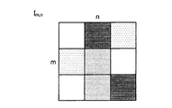
- FIG. 3 is an explanatory diagram for describing an overview of speckle contrast.
- the speckle contrast is calculated by dividing a standard deviation of pixel values by an average value of the pixel values in a plurality of pixels (for example, 3 pixels ⁇ 3 pixels, 5 pixels ⁇ 5 pixels, etc.) around the target pixel. Is done. Specifically, assuming that the pixel value of a pixel located at m rows and n columns (m and n are integers equal to or greater than 1) is Im , n , the speckle contrast is calculated as shown in (Equation 1) below. The formula is calculated for each pixel of interest.
- ⁇ m, n indicates a standard deviation of pixel values of a plurality of pixels centered on a pixel located at m rows and n columns.
- ⁇ I m, n > indicates the average value of the pixel values of a plurality of pixels centered on the pixel located in m rows and n columns.
- the speckle pattern changes in accordance with the movement, and a relatively long exposure time (for example, a change in the movement of the By setting an exposure time longer than a possible period, the speckle pattern imaged within the exposure time is averaged, and the speckle contrast is further reduced.
- FIG. 4 is an explanatory diagram for describing an overview of speckle contrast, and shows an image in which speckle is generated for each of a moving object and a non-moving object (that is, a speckle pattern becomes apparent). ) And an image based on the speckle contrast calculated for each pixel of the image.
- an image having speckles is also referred to as a “speckle image”.
- An image obtained by calculating the speckle contrast for each pixel of the speckle image and forming an image is also referred to as a “speckle contrast image”.
- FIG. 4 shows a speckle image and a speckle contrast image in a case where a blood simulating liquid flows through the flow path M111 simulating a blood vessel and a case where the liquid is not flowing.
- reference numeral V111 indicates an area where a speckle image is to be captured.
- Reference numeral V113 indicates an example of a speckle image captured when the liquid is not flowing through the flow path M111 (that is, when there is no flow).
- reference numeral V117 indicates an example of a speckle image captured when a liquid flows in the flow path M111 (that is, when there is a flow).
- FIG. 4 shows a speckle image and a speckle contrast image in a case where a blood simulating liquid flows through the flow path M111 simulating a blood vessel and a case where the liquid is not flowing.
- reference numeral V111 indicates an area where a speckle image is to be captured.
- Reference numeral V113 indicates an example of a speckle image captured when the liquid is not flowing through the flow
- the speckle image V117 is different from the speckle image V113 in that a portion corresponding to the flow path M111 having a flow and other portions (that is, a portion other than the flow path M111) It can be seen that there is a difference in speckle distribution between (a) and (no).
- ⁇ Circumflex over (V) ⁇ indicates a speckle contrast image generated by calculating a speckle contrast for each pixel of the speckle image V113.
- reference numeral V119 indicates a speckle contrast image generated by calculating speckle contrast for each pixel of the speckle image V117.
- a portion corresponding to the channel M111 that is, a moving portion
- another portion are included in the speckle contrast image V119 obtained when a liquid is caused to flow through the channel M111. It can be seen that the distribution of the calculation result of the speckle contrast is different between the portion (ie, the portion having no motion). From such characteristics, for example, when a blood vessel is an observation target, it is possible to obtain an image in which a blood flow is presented by generating a speckle contrast image based on an imaging result of a speckle image. .
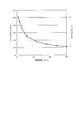
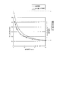
- FIG. 5 is an explanatory diagram for describing an example of a relationship between speckle contrast and movement of an object.
- the horizontal axis indicates the speed (mm / s) of the target object (that is, the object indicating the movement).
- the vertical axis indicates speckle contrast.
- the speckle contrast calculation result is higher as the speed of the object is lower, and the speckle contrast tends to decrease as the speed of the object increases.
- the range in which the speckle contrast value can be taken is also referred to as “dynamic range” for convenience.
- light reflected by the object may include two polarization components orthogonal to each other.
- Speckle itself is a phenomenon caused by light interference.
- two orthogonally polarized lights do not interfere with each other, light intensity is simply superimposed, and as a result, a speckle pattern is averaged. From such characteristics, it may be possible to obtain a higher speckle contrast by observing only one of the two polarized lights orthogonal to each other.
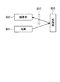
- FIG. 6 is an explanatory diagram for explaining the influence of the use of polarized light on the calculation result of speckle contrast, and schematically illustrates a configuration related to imaging of a speckle image.
- the light emitted from the light source 801 is reflected by the diffusion plate 805, and the speckle pattern is formed. get.
- a polarization filter 807 between the diffusion plate 805 and the imaging unit 803
- one of two orthogonally polarized lights included in the reflected light from the diffusion plate 805 can be used. Only the polarized light can be imaged by the imaging unit 803.
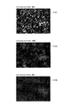
- FIG. 7 shows an example of images having different levels of speckle contrast. Specifically, in the example shown in FIG. 7, the speckle contrast of the image V101 is the highest, and the speckle contrast is sequentially lower in the order of the images V101, V103, and V105.
- the image V105 shown in FIG. 7 is obtained as a speckle contrast image by using the imaging result without interposing the polarizing filter 807.
- a speckle image having a higher speckle contrast like the image V103 or the image V101 shown in FIG. can be obtained.
- FIG. 8 is an explanatory diagram for describing another example of the relationship between the speckle contrast and the motion of the object, and illustrates an example in which polarized light is used for observing the object (that is, acquiring a speckle image). Is shown. Specifically, FIG. 8 additionally shows a result of observation using only one of two polarized light beams orthogonal to each other with respect to the example shown in FIG. In FIG. 8, the example shown as normal observation is the example shown in FIG. 5, that is, the case where the light from the target object (for example, the light reflected by the object) is observed without being separated into polarized light. An example of the characteristic is shown.
- observation with single polarized light shows an example of characteristics when only one polarized light is observed among two orthogonal polarized lights constituting light from a target object.
- the description “normal observation” indicates a case where light from a target object is observed without being separated into polarized light, unless otherwise specified.
- observation with a single polarized light unless otherwise specified, a plurality of polarized lights having different polarization directions included in light from a target object (for example, two polarized lights orthogonal to each other) ) Shows a case where only one polarized light is observed.
- the value of the speckle contrast tends to be higher in a state where the movement of the object is small (and, consequently, in a state where the object is stationary) as compared with the normal observation. It is in.
- the difference in the value of the speckle contrast between the normal observation and the observation with a single polarization becomes smaller (therefore, the difference is smaller). , The difference disappears). Due to such characteristics, observation with single polarized light causes a larger change in the value of the speckle contrast with respect to a change in the speed of the object (that is, a wider dynamic range) than normal observation.
- the present disclosure proposes a technique that enables observation of a moving diseased part in a more suitable manner.
- observation of an object with higher sensitivity for example, realization of a wider dynamic range
- efficient use of light from the object for example, the amount of light available for observation
- the present invention proposes a technique that makes it possible to achieve both of the above-described methods in a more suitable manner.
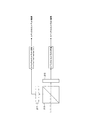
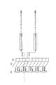
- FIG. 9 is an explanatory diagram for describing a basic idea of a technique relating to observation of an affected part in a medical observation system according to an embodiment of the present disclosure.
- reference numeral 213 indicates a branch optical system that separates incident light into a plurality of polarized lights having different polarization directions.
- the branching optical system 213 may be configured to include, for example, a polarizing beam splitter (PBS: Polarizing Beam Splitter).
- PBS Polarizing Beam Splitter
- the branching optical system 213 reflects, for example, a part of the polarized light (for example, p-wave and s-wave) included in the incident light and transmits another part of the polarized light, thereby Separate multiple polarizations.
- Reference numerals 215 and 217 each schematically show an image sensor.
- the light from the target object (for example, the light reflected by the object) is split into a plurality of polarizations (for example, reflected light) by the branching optical system 213.
- the light is separated into two polarized lights whose polarization directions are orthogonal to each other), and the separated polarized lights are individually detected by the imaging devices 215 and 217, respectively.
- the imaging devices 215 and 217 respectively.
- the polarized light transmitted through the branch optical system 213 is detected by the imaging element 215, and the polarized light reflected by the branch optical system 213 is detected. Is detected by the image sensor 217.
- the medical observation system includes at least one of the images individually captured by the imaging elements 215 and 217 (that is, images according to the imaging results of the respective polarizations). Using one of the images, a process related to observation of a target object (for example, an affected part) is executed. At this time, the medical observation system individually applies predetermined arithmetic processing to the images captured by the imaging elements 215 and 217, and uses at least one of the application results of the arithmetic processing for each image. Then, the processing related to the observation of the target object may be executed.
- the medical observation system calculates a speckle contrast for each pixel of an image (speckle image) corresponding to the imaging result of each of the imaging elements 215 and 217. Generate a speckle contrast image. Then, the medical observation system executes a process related to observation of the object (for example, the affected part) based on at least one of the speckle contrast images generated for each of the plurality of polarized lights separated from the light from the object. .
- the medical observation system may combine speckle contrast images generated for each of a plurality of polarizations.
- the medical observation system synthesizes the speckle contrast image generated for each polarization by averaging the pixel value for each pixel between the speckle contrast images generated for each of the plurality of polarizations. May be.
- the medical observation system may combine the speckle contrast images generated for each of the plurality of polarized lights based on the weight according to the light intensity of each of the plurality of polarized lights.
- the medical observation system assigns a weight corresponding to the light intensity of each of the plurality of polarizations.
- the reflected weighted average may be performed.
- the above-described method of synthesizing the speckle contrast image is merely an example, and the method is not particularly limited as long as the speckle contrast image generated for each of the plurality of polarizations can be synthesized. With such a configuration, it is possible to efficiently use the condensed light (in other words, light from an object) and obtain a brighter image.
- each of the speckle contrast images generated for each polarization has a wider dynamic range than the speckle contrast image generated in normal observation. That is, by combining the generated speckle contrast images generated for each polarization, the speckle contrast having a wider dynamic range than that of normal observation is maintained while maintaining the same brightness as that of normal observation. Images can be obtained.
- the speckle contrast is evaluated (calculated) for each of a plurality of polarizations for each minute region, and the analysis is performed by averaging the evaluation results. It is possible to reduce the feeling of noise in a later evaluation image. That is, as shown in FIG. 9, the collected light (for example, light from the affected part) is separated into two polarized lights, and the speckle contrast is evaluated (calculated) for each polarized light. Can be evaluated with twice as many sample pixels as in normal observation.
- speckle contrast is individually determined for each of a plurality of polarized lights separated from collected light (for example, light from an affected part). Etc. can be obtained. Therefore, in the medical observation system according to an embodiment of the present disclosure, various analyzes using such characteristics can be performed.
- a target object as affected part
- a specific polarization by using laser light as a light source.
- light reflected on the surface of the object is used.
- a specific polarization component when light reflected on the surface of the object is directly observed, stronger light (for example, brighter light) is observed as compared with the case where scattered light is observed.
- an image signal in other words, a pixel value
- a pixel value corresponding to the imaging result may be saturated in a portion where the influence of surface reflection is even better.
- speckle images are acquired for a plurality of polarizations having different polarization directions. From such characteristics, for example, even when a part of the speckle image corresponding to a part of the polarization is saturated, by using the speckle image corresponding to the other polarization, signal processing in a subsequent stage is performed. In the processing related to the observation of the affected part such as the above, the influence of surface reflection can be further reduced. This is not limited to a speckle image, but is also true of a speckle contrast image.
- a speckle image obtained for each of a plurality of polarizations having different polarization directions and a method of using a speckle contrast image generated based on a speckle image for each polarization are not particularly limited.
- one of a speckle image acquired for each polarization and a speckle contrast image generated for each polarization may be selected and used according to a predetermined condition.
- the speckle image or the speckle contrast image may be synthesized between a plurality of polarized lights, and a result of the synthesis may be used.
- the medical observation system according to the present disclosure by using at least one of a speckle image acquired for each polarization and a speckle contrast image generated for each polarization, observation of an affected part is possible. Such various processes can be realized.
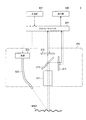
- FIG. 10 is an explanatory diagram for describing an example of a configuration of a medical observation system according to an embodiment of the present disclosure.
- FIG. 10 is obtained by irradiating the affected part with light of a predetermined wavelength (for example, narrow-band light) and imaging light from the affected part (for example, light reflected by the affected part).
- a predetermined wavelength for example, narrow-band light
- 1 shows an example of a schematic system configuration of a medical observation system when observing an affected part based on a speckle image.
- the medical observation system shown in FIG. 10 is also referred to as “medical observation system 2” for convenience.
- the medical observation system 2 includes a control unit 201, an imaging unit 203, an input unit 207, and an output unit 209.
- the input unit 207 and the output unit 209 correspond to the input device 147 and the display device 141 in the example illustrated in FIG.
- the imaging unit 203 includes, for example, an imaging optical system 211, a branching optical system 213, imaging elements 215 and 217, and a light source 223.
- the light source 223 corresponds to an example of the light source device 143 in the example shown in FIG.
- the light emitted from the light source 223 is transmitted through a transmission cable 225 configured to be able to guide the light using an optical fiber or the like, and is irradiated on the diseased part M101.
- the wavelength of the light emitted from the light source 223 may be controlled or the light source 223 itself may be selectively switched according to the observation target and the observation method.
- a light source configured to be able to emit visible light (for example, RGB light) may be applied as the light source 223.
- a light source configured to emit a wavelength for exciting a phosphor to be used may be applied as the light source 223.
- a light source configured to emit a wavelength for exciting a phosphor to be used
- the near-infrared light can be irradiated as the light source 223.
- a configured light source may be applied.
- the branch optical system 213 and the imaging devices 215 and 217 correspond to the branch optical system 213 and the imaging devices 215 and 217 described with reference to FIG. That is, the branching optical system 213 separates the light (for example, light from the affected part, which is also simply referred to as “incident light”) incident on the imaging unit 203 into a plurality of polarized lights having different polarization directions, and separates the light. A part of the polarized light is guided to the image sensor 215, and another part of the polarized light is guided to the image sensor 217.
- the branching optical system 213 separates the light (for example, light from the affected part, which is also simply referred to as “incident light”) incident on the imaging unit 203 into a plurality of polarized lights having different polarization directions, and separates the light.
- a part of the polarized light is guided to the image sensor 215, and another part of the polarized light is guided to the image sensor 217.
- Each of the imaging elements 215 and 217 is provided at the subsequent stage of the branch optical system 213, and individually detects polarized light separated from incident light by the branch optical system 213.
- imaging elements 215 and 217 for example, imaging elements such as CCD and CMOS can be applied.
- the control unit 201 corresponds to the CCU 139 shown in FIG. 1, and controls the operation of each component of the medical observation system 2.
- the control unit 201 may control the operation of the light source 223 according to the observation target and the observation method.
- the control unit 201 may control an operation related to imaging of an image by at least one of the imaging elements 215 and 217.
- the control unit 201 may control the imaging conditions of the image (for example, shutter speed, aperture, gain, and the like).
- the control unit 201 may acquire an image corresponding to an imaging result of at least one of the imaging elements 215 and 217, and cause the output unit 209 to present the image.
- the control unit 201 may perform predetermined image processing on the acquired image.
- control unit 201 may control the operation of each unit according to the detection results of various states.
- the control unit 201 generates a blur (for example, a camera shake) that appears in the imaging results of the imaging elements 215 and 217 in accordance with the detection result of the movement of the imaging unit 203 by various sensors (not shown). May be corrected.
- the control unit 201 may execute the above-described various processes according to an instruction from the user input via the input unit 207.
- the example described with reference to FIG. 10 is merely an example, and does not necessarily limit the configuration of the medical observation system according to an embodiment of the present disclosure. That is, as long as the basic idea of the medical observation system according to the embodiment described above is not deviated, a part of the configuration may be appropriately changed according to the observation target and the observation method.
- FIG. 11 is a block diagram illustrating an example of a functional configuration of a medical observation system according to an embodiment of the present disclosure.
- FIG. 11 illustrates the configuration of the medical observation system according to the present embodiment, in particular, based on a speckle image corresponding to a detection result of each of a plurality of polarized lights separated from light from the affected part.
- a description will be given focusing on a portion that executes various processes related to observation of the image.
- the medical observation system shown in FIG. 11 is also referred to as “medical observation system 3” for convenience.
- the medical observation system 3 includes a control unit 301, a detection unit 313, and an output unit 317.
- the output unit 317 may correspond to the output unit 209 illustrated in FIG. Therefore, detailed description of the output unit 317 is omitted.
- the detection unit 313 includes a first imaging unit 313a and a second imaging unit 313b.
- the detection unit 313 may correspond to, for example, the imaging unit 203 illustrated in FIG.
- One of the first imaging unit 313a and the second imaging unit 313b may correspond to the imaging device 215 illustrated in FIG. 5, and the other may correspond to the imaging device 217 illustrated in FIG.
- a part of the polarization is imaged (detected) by the first imaging unit 313a
- Polarized light is imaged (detected) by the second imaging unit 313b.
- first imaging unit 313a and the second imaging unit 313b can apply substantially the same configuration as the imaging elements 215 and 217 illustrated in FIG. 5 as described above, and thus a detailed description is omitted.
- Each of the first imaging unit 313a and the second imaging unit 313b outputs an image (for example, a speckle image) corresponding to the imaging result of the corresponding polarization to the control unit 301.
- the control unit 301 may correspond to the control unit 201 shown in FIG. As shown in FIG. 11, the control unit 301 includes a calculation unit 305 and a processing unit 303.
- the calculation unit 305 executes various calculation processes based on the polarization imaging results (detection results) of the first imaging unit 313a and the second imaging unit 313b.
- the calculation unit 305 includes a first calculation unit 305a and a second calculation unit 305b.
- the first calculation unit 305a performs various calculation processes based on the result of the polarization imaging performed by the first imaging unit 313a.
- the second calculation unit 305b performs various calculation processes based on the polarization imaging result obtained by the second imaging unit 313b.
- the first calculation unit 305a and the second calculation unit 305b may be provided as hardware independent configurations. Further, the first calculation unit 305a and the second calculation unit 305b may be realized by software such as a process in which each of the processing units individually executes a process.
- the arithmetic processing executed by the first arithmetic unit 305a and the second arithmetic unit 305b includes, for example, processing related to generation of a speckle contrast image.
- the first calculation unit 305a calculates a speckle contrast by using each pixel of an image (speckle image) acquired in accordance with the polarization imaging result by the first imaging unit 313a as a pixel of interest.
- a speckle contrast image is generated based on the result of (1).
- the second calculation unit 305b generates a speckle contrast image based on an image obtained in accordance with the result of the polarization imaging performed by the second imaging unit 313b.
- the first calculation unit 305a and the second calculation unit 305b may appropriately change the calculation process applied to the polarization imaging result in accordance with the process related to the observation of the affected part performed at a later stage.
- the first calculation unit 305a and the second calculation unit 305b may execute a process related to detection (extraction) of the optical frequency shift based on the imaging result of the corresponding polarization.
- the arithmetic unit 305 outputs, to the processing unit 303, each of the arithmetic results obtained for each polarization by the first arithmetic unit 305a and the second arithmetic unit 305b.
- the calculation unit 305 uses the speckle contrast generated separately for each polarization by the first calculation unit 305a and the second calculation unit 305b. A description will be given focusing on a case where an image is output to the processing unit 303. Note that, in this case, the calculation unit 305 may output the speckle image from which the speckle contrast image is generated (that is, an image corresponding to the imaging result of each polarized light) to the processing unit 303.
- the processing unit 303 obtains, from the calculation unit 305, the result of the operation individually applied to each of the plurality of polarizations separated from the light from the affected part and having different polarization directions, and obtains at least one of the results of the operation for each polarization.
- the processing related to the observation of the affected part is executed depending on the condition. For example, the processing unit 303 acquires, from the calculation unit 305, a speckle contrast image generated separately for each of a plurality of polarized lights separated from the light from the affected part and having different polarization directions.
- the processing unit 303 executes a process related to observation of the diseased part based on at least one of the individually generated speckle contrast images generated for each of the plurality of polarizations.
- the processing unit 303 includes an analysis unit 307, an image processing unit 309, , An output control unit 311.
- the analysis unit 307 performs various analysis processes based on the acquired speckle contrast image.
- the analysis unit 307 determines an object included in an area based on a pixel value of a pixel included in at least a part of the acquired speckle contrast image (that is, a calculated value of the speckle contrast). (In other words, the moving speed of the affected part to be observed) may be calculated.
- the analysis unit 307 may extract a characteristic part (for example, a part corresponding to an affected part) from the speckle contrast image by performing image analysis on the speckle contrast image.
- a characteristic part for example, a part corresponding to an affected part
- the analysis unit 307 may perform a predetermined determination based on the result of the image analysis by performing an image analysis on the speckle contrast image. As a specific example, the analysis unit 307 may determine whether at least a part of the speckle contrast image is saturated by evaluating the pixel value of each pixel of the speckle contrast image. By utilizing such a determination result, for example, in a speckle contrast image corresponding to each of a plurality of polarizations, when saturation occurs in a speckle contrast image corresponding to a part of the polarization, another polarization Can be selected as a target of the subsequent processing.
- the analysis unit 307 may analyze only the speckle contrast image corresponding to any one of the plurality of polarizations. As another example, the analysis unit 307 may analyze speckle contrast images corresponding to a plurality of polarizations, respectively. As another example, the analysis unit 307 may analyze an image obtained by combining speckle contrast images corresponding to a plurality of polarizations, respectively. Note that the combination is performed by, for example, an image processing unit 309 described below.
- the image processing unit 309 performs various image processing on the acquired speckle contrast image.
- the image processing unit 309 may execute a process related to adjustment of brightness, contrast, color tone, and the like on each of the acquired speckle contrast images.
- the image processing unit 309 may synthesize a speckle contrast image corresponding to each of a plurality of polarizations. As a specific example, the image processing unit 309 averages a pixel value for each pixel between the speckle contrast images corresponding to each of the plurality of polarizations, thereby forming a speckle contrast image corresponding to each of the plurality of polarizations. They may be synthesized.
- each of the analysis unit 307 and the image processing unit 309 is not limited to the speckle contrast image, and the speckle image from which the speckle contrast image is generated may be subjected to the above-described various processes.
- the output control unit 311 presents the information by causing the output unit 317 to output various information as display information.
- the output control unit 311 may cause the output unit 317 to output a speckle contrast image generated for each polarization or a speckle image from which the speckle contrast image is generated as display information.
- the output control unit 311 converts the image in which the speckle contrast image corresponding to each of the plurality of polarizations is synthesized by the image processing unit 309 or the image in which the speckle image which is the generation source of the speckle contrast image is synthesized. , May be output to the output unit 317 as display information.
- the output control unit 311 may cause the output unit 317 to output information (for example, the speed of an object to be observed) according to the analysis result of the analysis unit 307.
- the output control unit 311 may control information to be output to the output unit 317 according to the result of the determination by the analysis unit 307.
- the output control unit 311 may cause the output unit 317 to output two or more pieces of information among the various types of information described above in association with each other.
- the output control unit 311 outputs display information in which information according to the calculation result of the speed of the object calculated based on the speckle contrast image is superimposed on the speckle contrast image. 317 may be output.
- the output control unit 311 may cause the output unit 317 to output display information in which two or more images among the speckle contrast images for each polarization or the speckle images for each polarization are associated with each other.
- the output control unit 311 may cause the output unit 317 to output display information in which the two or more images are displayed side by side.
- the output control unit 311 outputs a so-called PIP (Picture @ In @ Picture) image in which another image is superimposed on a partial area of a partial image to the output unit 317 as display information. You may let it. Further, the output control unit 311 may selectively switch information to be output to the output unit 317 as display information according to a predetermined condition.
- PIP Picture @ In @ Picture
- the above-described functional configuration is merely an example, and the functional configuration of the medical observation system is not necessarily limited to the example illustrated in FIG. 11 as long as the operation of each configuration described above can be realized.
- at least one of the detection unit 313 and the output unit 317 and the control unit 301 may be integrally configured.
- some functions of the control unit 301 may be provided outside the control unit 301.
- at least a part of the function of the control unit 301 may be realized by a plurality of devices operating in cooperation with each other.
- a part of the configuration of the medical observation system may be changed, and other configurations may be used. It may be added separately.
- an apparatus including a configuration corresponding to the control unit 301 shown in FIG. 11 corresponds to an example of a “medical observation apparatus”.
- an example of a functional configuration of the medical observation system according to an embodiment of the present disclosure, in particular, an example of a functional configuration of a control unit that controls the operation of each configuration of the medical observation system It was explained focusing on.
- FIG. 12 is a flowchart illustrating an example of a flow of a series of processes of the medical observation system according to an embodiment of the present disclosure.
- the detection unit 313 individually detects (images) each of a plurality of polarized lights having different polarization directions from which the light from the affected part is separated by the branch optical system 213 or the like shown in FIG.
- the detection unit 313 individually outputs images (speckle images) corresponding to the detection results of the plurality of polarizations to the control unit 301 (S101).
- the control unit 301 (arithmetic unit 305) individually obtains images from the detection unit 313 according to the detection results of the plurality of polarizations.
- the control unit 301 (arithmetic unit 305) individually applies predetermined arithmetic processing to the detection results of each of the plurality of polarizations.
- the control unit 301 (arithmetic unit 305) calculates a speckle contrast for each of a plurality of polarized lights, using each pixel of an image (speckle image) corresponding to a detection result of the polarized light as a pixel of interest, A speckle contrast image is generated based on the calculation result (S103).
- control unit 301 executes a process related to observation of the diseased part in accordance with a result of the calculation with respect to at least a part of the polarization results among the calculation results of the detection results of the plurality of polarizations.
- control unit 301 performs a process related to observation on the diseased part based on at least a part of the speckle contrast images generated for each of the plurality of polarizations ( S105).
- the control unit 301 calculates the moving speed of the object included in the area based on the pixel values of the pixels included in at least a part of the area of the speckle contrast image. Is also good. Further, the control unit 301 (the output control unit 311) may cause the output unit 317 to output at least a part of the speckle contrast images among the speckle contrast images generated for each polarization as display information. Further, the control unit 301 (image processing unit 309) averages the pixel values of the speckle contrast images corresponding to the respective polarizations for each pixel, thereby obtaining the speckle contrast image corresponding to the respective polarizations. May be synthesized. In this case, the combined image may be the target of the processing related to the analysis or the processing related to the output.
- FIG. 13 is an explanatory diagram for describing an outline of a medical observation system according to Modification Example 1, and has a configuration for separating light from an affected part into a plurality of polarized lights and individually detecting each polarized light. An example is shown.
- the medical observation system according to the first modification is different from the medical observation system according to the above embodiment in that light from an affected part is separated into a plurality of polarized lights having different polarization directions and each polarized light is individually detected by one imaging device.
- This is different from the observation system (for example, see FIGS. 9 and 10).
- reference numeral 231 indicates a branch optical system that separates incident light into a plurality of polarized lights having different polarization directions, and corresponds to the branch optical system 213 in the example illustrated in FIG. 9.
- Reference numeral 233 schematically shows an image sensor, and the image sensors 215 and 217 in the example shown in FIG. 9 and the detector 313 (that is, the first imager 313a and the second imager 313) in the example shown in FIG. It corresponds to the imaging unit 313b).
- a part of the polarized light is referred to in the light receiving surface of the image sensor 233.
- the light is guided (imaged) in a region indicated by reference numeral 235a.
- other polarized light is guided (imaged) to a region indicated by reference numeral 235b on the light receiving surface of the image sensor 233. That is, in the example illustrated in FIG. 13
- images are individually generated based on the detection results (imaging results) of the polarizations in the regions 235 a and 235 b on the light receiving surface of the imaging element 233, and each image is generated. Speckle contrast processing is individually performed on the image. As a result, speckle contrast images are individually generated for each of the plurality of polarized lights separated from the incident light.
- the medical observation system can capture a speckle image for each of a plurality of polarizations using one imaging device.
- a difference may occur between the plurality of polarized lights separated from the incident light in the optical path until each polarized light is guided to the corresponding region on the imaging surface of the imaging element 233. is there.
- the optical path of at least one polarized light may be adjusted by interposing another optical system such as a relay lens.
- FIG. 13 As described above, with reference to FIG. 13 as a first modification, an example of a configuration for separating light from an affected part into a plurality of polarized lights and individually detecting (imaging) each polarized light, in particular, an example shown in FIG.
- the description has been made by focusing on the configuration corresponding to the branch optical system 213 and the imaging elements 215 and 217 in FIG.
- FIG. 14 is an explanatory diagram for describing an overview of a medical observation system according to Modification Example 2 and has a configuration for separating light from an affected part into a plurality of polarized lights and individually detecting each polarized light. An example is shown.
- the light from the affected part is separated into a plurality of polarized lights having different polarization directions, and each polarized light is individually separated by one image sensor. To be detected.
- the light receiving surface of the image sensor is divided into a plurality of regions in smaller units than the case of the medical observation system according to the first modification. For each of the regions, one of a plurality of polarized lights separated from the incident light is guided (imaged).
- reference numeral 253 indicates a polarization separation element that separates incident light into a plurality of polarized lights having different polarization directions. That is, in the example illustrated in FIG. 14, the configuration corresponding to the branch optical system 231 in the example illustrated in FIG. 13 includes a plurality of polarization splitters 253.
- the polarization separation element 253 can be composed of, for example, PBS, anisotropic crystal, or the like.
- reference numeral 255 schematically shows an image sensor, and corresponds to the image sensor 233 in the example shown in FIG. That is, in the example illustrated in FIG. 14, the image sensor 255 includes the image sensors 215 and 217 in the example illustrated in FIG.
- each of the plurality of polarization separation elements 253 separates incident light into a plurality of polarizations having different polarization directions. Then, each of the plurality of polarized lights separated from the incident light by the plurality of polarization separation elements 253 is guided (imaged) to a different area on the light receiving surface of the imaging element 255.
- an optical system 251 for guiding a part of the incident light to the polarization separation element 253 may be provided in a stage preceding the polarization separation element 253.
- the optical system 251 can be configured as, for example, an array lens in which a condenser lens is arrayed.
- some of the polarized light is indicated by an area 257a on the light receiving surface of the image sensor 255.
- the light is guided (imaged).
- other polarized light is guided (imaged) to a region indicated by reference numeral 257b on the light receiving surface of the image sensor 255.
- a region where each of the plurality of polarized lights separated by each polarization separation element 253 is guided forms a light receiving surface of the imaging element 255, such as a line or a tile. May be defined as an area including one or more unit areas.
- the detection result of the polarized light in the region where the polarized light having the same polarization direction is guided among the regions on the light receiving surface of the imaging element 255 is combined, so that the incident light is separated.
- An image (speckle image) is individually generated for each of the plurality of polarized lights. Then, speckle contrast processing is performed on each of the images generated for each polarization, so that a speckle contrast image corresponding to the polarization is generated.
- the medical observation system according to Modification 2 captures a speckle image for each of a plurality of polarizations using one image sensor, similarly to the medical observation system according to Modification 1. It is possible to do. Further, the medical observation system according to Modification 2 is different from the medical observation system according to Modification 1 in that each of the plurality of polarized lights whose incident light has been separated by the polarization separation element 253 has an imaging surface of the imaging element 255. It is possible to further reduce the difference in the optical path until the light is guided to the corresponding area.
- FIG. 14 As described above, with reference to FIG. 14 as Modification Example 2, another example of a configuration for separating light from an affected part into a plurality of polarized lights and individually detecting (imaging) each polarized light is illustrated in FIG. The description has been given by focusing on the configuration corresponding to the branch optical system 213 and the imaging elements 215 and 217 in the illustrated example.
- the configuration of the medical observation system according to Modification 3 is not necessarily limited.
- the medical observation system may combine a speckle image according to the detection result of each polarized light by a method similar to the method of combining the above-described speckle contrast image.
- treatment may be performed while applying saline to prevent the surface from drying out.
- the observation is performed in a state where the liquid is present on the surface, and there is a possibility that surface reflection occurs at the interface between the liquid and the air.
- an image for example, a speckle contrast image
- Modification 4 An example of control according to the detection result of each polarized light
- Modification 4 an example of control according to the detection result of each polarized light
- FIG. 15 is an explanatory diagram for describing an example of a process of the medical observation system according to Modification 4, and illustrates an example of a process flow for further reducing the influence of surface reflection.
- an image signal corresponding to the imaging result in other words, , Pixel value
- the subsequent processing is selectively switched according to whether or not each of the image signals corresponding to the detection results of the plurality of polarized lights from which the light from the affected part is separated is saturated.
- first polarized light first polarized light
- second polarized light second polarized light
- the medical observation system compares the calculation result of speckle contrast (for example, a speckle contrast image) for each of the first polarized light and the second polarized light with the observation of the affected part (for example, the movement of blood flow). (S213).
- speckle contrast for example, a speckle contrast image
- the medical observation system averages the calculation results of the speckle contrast between the first polarized light and the second polarized light, and uses the averaged speckle contrast for observing the affected part.
- the medical observation system performs The calculation result of the speckle contrast for the first polarized light is used for observation of the affected part (S211).
- the detection result of the first polarized light is saturated (S201, YES) and the detection result of the second polarized light is not saturated (S203, NO)
- the medical observation system performs the second observation.
- the calculation result of the speckle contrast for the two polarized lights is used for observation of the affected part (S209).
- the medical observation system may notify the user via the output unit that the detection results of both the first polarization and the second polarization are saturated (S207).
- a cerebral aneurysm refers to a part of a blood vessel (artery) of the brain that is swollen and weakened. Large bulging cerebral aneurysms can rupture in the future and cause bleeding. Therefore, in order to prevent blood from flowing into the aneurysm in a preventive manner, for example, a treatment may be performed to cut off the blood flow by clipping (ie, clipping) the neck of the aneurysm. At this time, blood observation is performed to confirm whether or not the flow of blood into the aneurysm is blocked by clipping (that is, whether or not blood has flowed into the aneurysm).
- clipping ie, clipping
- a perforator is a small blood vessel, clipping this blood vessel can cause a serious impairment in the functioning of the brain where it is supplying oxygen and nutrients.
- this is an important perforator, it is a blood vessel of about 1 mm or less, and there are situations where it is difficult to evaluate the presence or absence of blood flow using an ultrasonic Doppler blood flow meter.
- a technique for observing an object based on the result of imaging such as speckle blood flow imaging, has a higher resolution than an ultrasonic Doppler blood flow meter, and confirms the presence or absence of blood flow even in a blood vessel of 1 mm or less. It is possible.
- the average value of the luminance and the luminance value in a certain calculation area (for example, a pixel area of a predetermined size centering on the target pixel) are calculated. Calculate the deviation.
- the calculation area is made larger, the resolution of the obtained speckle contrast image tends to decrease, and the size of the calculation area is often limited.
- the speckle contrast is calculated in the calculation region whose size is limited, the variation of the calculated speckle contrast value is relatively large according to the magnitude of the pixel value included in the calculation region. Tend to be.
- the speckle contrast image obtained under such conditions looks like a so-called noise-like image in which the luminance varies as a whole.
- the medical observation system as described above, light from an observation target (affected part) is separated into a plurality of polarized lights, and a speckle pattern is individually captured for each polarized light.
- the speckle pattern formed for each polarization is different, so that the value of the speckle contrast calculated for each polarization is also different. From such characteristics, for example, by combining speckle contrast images generated for each polarization by averaging the pixel values of each pixel, it is possible to further reduce variations in luminance such as noise. (That is, it is possible to obtain an image with reduced noise.)
- the description has been made focusing on a technique for observing an affected part mainly using a speckle image or a speckle contrast image, but it is not necessarily limited to a target to which the medical observation system according to the present disclosure is applied. Absent. That is, the medical observation system according to the present disclosure separates light from an observation target (for example, an affected part) into a plurality of polarized lights having different polarization directions, and individually detects each of the plurality of polarized lights. It has a characteristic configuration in which processing related to observation of a target is executed based on at least one of the detection results of the respective polarized lights. Therefore, for example, a medical observation system according to the present embodiment is used for a system that enables observation of an object by capturing an image of the object using an image sensor, and an observation method using the system. It is possible to apply.
- a method using the above-described optical Doppler and a method using a fluorescent agent may be used.
- a method using optical Doppler for example, extraction of an optical frequency shift is performed based on detection results (imaging results) of a plurality of polarized lights separated from light from an observation target. May be individually executed. Then, the speed of the observation target (for example, the speed of blood flow) may be calculated based on at least one of the frequency shift extraction results corresponding to the plurality of polarizations. Further, the velocity of the observation target (for example, the velocity of the blood flow) may be calculated by combining and using the extraction results of the frequency shifts corresponding to the plurality of polarizations.
- the method of using a fluorescent agent is a method of introducing a fluorescent agent such as an ICG agent into blood and observing a fluorescent image.
- a fluorescent agent such as an ICG agent
- the fluorescence emitted by the fluorescent agent is imaged using the imaging device, and the fluorescence along the blood vessel follows the blood flow after the introduction of the fluorescent agent. Is observed. Therefore, for example, by performing a temporal analysis based on the observation result of the fluorescence, it is possible to obtain information on the blood flow.
- At least one of the imaging results (i.e., the fluorescence image) of each of a plurality of polarized lights separated from the light from the observation target is used for the above-described time period. Analysis may be performed. Further, the imaging results of the plurality of polarized lights may be combined based on a predetermined condition, and the above-described temporal analysis may be performed on the combined result.
- the description has been made focusing on the case where the present invention is mainly applied to blood flow observation.
- the characteristic configuration of the medical observation system according to the present embodiment described above can be used, the medical It goes without saying that the application target of the observation system is not limited to blood flow observation.
- FIG. 16 is a functional block diagram illustrating a configuration example of a hardware configuration of an information processing device included in the medical observation system according to an embodiment of the present disclosure.
- the information processing device 900 configuring the medical observation system mainly includes a CPU 901, a ROM 902, and a RAM 903.
- the information processing device 900 further includes a host bus 907, a bridge 909, an external bus 911, an interface 913, an input device 915, an output device 917, a storage device 919, a drive 921, and a connection port 923. And a communication device 925.
- the CPU 901 functions as an arithmetic processing device and a control device, and controls the entire operation or a part of the operation in the information processing device 900 according to various programs recorded in the ROM 902, the RAM 903, the storage device 919, or the removable recording medium 927.
- the ROM 902 stores programs used by the CPU 901 and operation parameters.
- the RAM 903 temporarily stores a program used by the CPU 901, parameters that appropriately change in execution of the program, and the like. These are interconnected by a host bus 907 constituted by an internal bus such as a CPU bus. Note that each component of the control unit 301 shown in FIG.
- the arithmetic unit 305 that is, the first arithmetic unit 305a and the second arithmetic unit 305b
- the processing unit 303 that is, the analyzing unit 307, the image processing unit 309, And the output control unit 311 can be realized by the CPU 901.
- the host bus 907 is connected to an external bus 911 such as a PCI (Peripheral Component Interconnect / Interface) bus via a bridge 909.
- the input device 915, the output device 917, the storage device 919, the drive 921, the connection port 923, and the communication device 925 are connected to the external bus 911 via the interface 913.
- the input device 915 is an operation unit operated by the user, such as a mouse, a keyboard, a touch panel, a button, a switch, a lever, and a pedal.
- the input device 915 may be, for example, a remote control unit (so-called remote controller) using infrared rays or other radio waves, or an externally connected device such as a mobile phone or a PDA corresponding to the operation of the information processing device 900. 929.
- the input device 915 includes, for example, an input control circuit that generates an input signal based on information input by a user using the above-described operation means and outputs the input signal to the CPU 901.
- the user of the information processing device 900 can input various data to the information processing device 900 and instruct a processing operation.
- the output device 917 is a device that can visually or audibly notify the user of the acquired information.
- Such devices include CRT display devices, liquid crystal display devices, plasma display devices, display devices such as EL display devices and lamps, audio output devices such as speakers and headphones, and printer devices.
- the output device 917 outputs, for example, results obtained by various processes performed by the information processing device 900.
- the display device displays results obtained by various processes performed by the information processing device 900 as text or images.
- the audio output device converts an audio signal including reproduced audio data, acoustic data, and the like into an analog signal and outputs the analog signal. Note that the output unit 317 illustrated in FIG. 11 can be realized by the output device 917.
- the storage device 919 is a data storage device configured as an example of a storage unit of the information processing device 900.
- the storage device 919 is configured by, for example, a magnetic storage device such as an HDD (Hard Disk Drive), a semiconductor storage device, an optical storage device, or a magneto-optical storage device.
- the storage device 919 stores programs executed by the CPU 901 and various data.
- the drive 921 is a reader / writer for a recording medium, and is built in or externally attached to the information processing apparatus 900.
- the drive 921 reads information recorded on a removable recording medium 927 such as a mounted magnetic disk, optical disk, magneto-optical disk, or semiconductor memory, and outputs the information to the RAM 903.
- the drive 921 can also write data on a removable recording medium 927 such as a mounted magnetic disk, optical disk, magneto-optical disk, or semiconductor memory.
- the removable recording medium 927 is, for example, a DVD medium, an HD-DVD medium, or a Blu-ray (registered trademark) medium.
- the removable recording medium 927 may be a Compact Flash (registered trademark) (CF: CompactFlash), a flash memory, an SD memory card (Secure Digital memory card), or the like. Further, the removable recording medium 927 may be, for example, an IC card (Integrated Circuit card) on which a non-contact type IC chip is mounted, an electronic device, or the like.
- CF CompactFlash
- SD memory card Secure Digital memory card
- the connection port 923 is a port for directly connecting to the information processing device 900.
- Examples of the connection port 923 include a USB (Universal Serial Bus) port, an IEEE 1394 port, and a SCSI (Small Computer System Interface) port.
- Other examples of the connection port 923 include an RS-232C port, an optical audio terminal, and an HDMI (registered trademark) (High-Definition Multimedia Interface) port.
- the communication device 925 is, for example, a communication interface including a communication device for connecting to a communication network (network) 931.
- the communication device 925 is, for example, a communication card for a wired or wireless LAN (Local Area Network), Bluetooth (registered trademark), or WUSB (Wireless USB).
- the communication device 925 may be a router for optical communication, a router for ADSL (Asymmetric Digital Subscriber Line), a modem for various kinds of communication, or the like.
- the communication device 925 can transmit and receive signals and the like to and from the Internet and other communication devices in accordance with a predetermined protocol such as TCP / IP.
- the communication network 931 connected to the communication device 925 is configured by a network or the like connected by wire or wirelessly, and may be, for example, the Internet, a home LAN, infrared communication, radio wave communication, satellite communication, or the like. .
- each of the above components may be configured using a general-purpose member, or may be configured by hardware specialized for the function of each component. Therefore, it is possible to appropriately change the hardware configuration to be used according to the technical level at the time of implementing the present embodiment.
- various configurations corresponding to the information processing apparatus 900 included in the medical observation system are naturally provided.
- a computer program for realizing each function of the information processing device 900 included in the medical observation system according to the present embodiment as described above can be created and mounted on a personal computer or the like.
- a computer-readable recording medium in which such a computer program is stored can be provided.
- the recording medium is, for example, a magnetic disk, an optical disk, a magneto-optical disk, a flash memory, or the like.
- the above-described computer program may be distributed, for example, via a network without using a recording medium.
- the number of computers that execute the computer program is not particularly limited. For example, a plurality of computers (for example, a plurality of servers) may execute the computer program in cooperation with each other.
- FIG. 17 is an explanatory diagram for describing an application example of the medical observation system according to an embodiment of the present disclosure, and illustrates an example of a schematic configuration of a microscope imaging system. Specifically, FIG. 17 illustrates an example in which a surgical video microscope apparatus having an arm is used as an application example in which the microscope imaging system according to an embodiment of the present disclosure is used. I have.
- FIG. 17 schematically shows a state of a treatment using a video microscope apparatus for surgery.
- a doctor who is a practitioner (user) 820 uses a surgical instrument 821 such as a scalpel, forceps, forceps, or the like to perform a treatment (patient) on a treatment table 830.
- a state in which an operation is performed on the 840 is illustrated.
- the term “treatment” is a general term for various medical treatments, such as surgery and examination, performed by a doctor who is a user 820 on a patient who is a treatment target 840.
- the state of the operation is illustrated as an example of the operation.
- the operation using the video microscope for operation 810 is not limited to the operation, and may be various other operations. .
- a surgical video microscope apparatus 810 is provided beside the treatment table 830.
- the surgical video microscope apparatus 810 includes a base 811 serving as a base, an arm 812 extending from the base 811, and an imaging unit 815 connected to a tip of the arm 812 as a tip unit.
- the arm 812 includes a plurality of joints 813a, 813b, 813c, a plurality of links 814a, 814b connected by the joints 813a, 813b, and an imaging unit 815 provided at the tip of the arm 812.
- the arm 812 has three joints 813a to 813c and two links 814a and 814b.
- the positions and positions of the arm 812 and the imaging unit 815 are determined.
- the number and shape of the joints 813a to 813c and the links 814a and 814b, the directions of the drive axes of the joints 813a to 813c, and the like are appropriately set so as to realize the desired degree of freedom in consideration of the degree of freedom of the posture. Good.
- the joints 813a to 813c have a function of rotatably connecting the links 814a and 814b to each other, and the rotation of the joints 813a to 813c controls the driving of the arm 812.
- the position of each component of the surgical video microscope device 810 means a position (coordinate) in a space defined for drive control
- the posture of each component is , The direction (angle) with respect to an arbitrary axis in a space defined for drive control.
- the driving (or driving control) of the arm 812 refers to the driving (or driving control) of the joints 813a to 813c and the driving (or driving control) of the joints 813a to 813c. Means that the position and posture of each component of the arm 812 is changed (change is controlled).
- the imaging unit 815 is connected to the tip of the arm 812 as a tip unit.
- the imaging unit 815 is a unit that acquires an image of an imaging target, and is, for example, a camera that can capture a moving image or a still image.
- the posture of the arm unit 812 and the imaging unit 815 is operated by the surgical video microscope device 810 such that the imaging unit 815 provided at the distal end of the arm unit 812 captures an image of the treatment site of the operation target 840. And position are controlled.
- the configuration of the imaging unit 815 connected as a tip unit to the tip of the arm 812 is not particularly limited.
- the imaging unit 815 is configured as a microscope that acquires an enlarged image of an imaging target.
- the imaging unit 815 may be configured to be detachable from the arm unit 812. With such a configuration, for example, the imaging unit 815 corresponding to the intended use may be appropriately connected to the tip of the arm 812 as a tip unit.
- the imaging unit 815 for example, an imaging device to which the branch optical system according to the above-described embodiment is applied can be applied. That is, in this application example, the imaging unit 815 or the surgical video microscope device 810 including the imaging unit 815 can correspond to an example of a “medical observation device”. In this description, the description has been made focusing on the case where the imaging unit 815 is applied as the distal end unit. However, the distal end unit connected to the distal end of the arm 812 is not necessarily limited to the imaging unit 815.
- a display device 850 such as a monitor or a display is provided at a position facing the user 820.
- the image of the treatment site captured by the imaging unit 815 is displayed on the display screen of the display device 850 as an electronic image.
- the user 820 performs various treatments while viewing the electronic image of the treatment site displayed on the display screen of the display device 850.
- the technique according to the present disclosure described above can be applied without departing from the basic idea of the medical observation system according to an embodiment of the present disclosure without being limited to the above.
- the present invention is not limited to a system to which the endoscope or the operation microscope described above is applied, and a system in which an image of an affected part can be observed by capturing an image of the affected part by an imaging device of a desired form.
- the technology according to the present disclosure described above can be appropriately applied.
- the medical observation system is configured as a microscope imaging system including a microscope unit.
- the medical observation system includes a light source that illuminates an affected part, a branch optical system, a detection unit, a calculation unit, and a processing unit.
- the branching optical system separates the light from the affected part into a plurality of polarized lights having different polarization directions.
- the detection unit individually detects each of the plurality of polarized lights.
- the calculation unit individually calculates the speckle contrast based on the detection results of the plurality of polarized lights.
- the processing unit executes a process related to the observation of the affected part based on at least one of the calculation results of the speckle contrast corresponding to each of the plurality of polarized lights.
- the processing unit may calculate an average of the calculation results of the speckle contrast corresponding to each of the plurality of polarizations, and execute a process related to observation of the diseased part based on the calculation result of the average.
- the speckle contrast calculated individually for each polarization as described above has a greater change with respect to the speed of movement of the affected part compared to the speckle contrast calculated without separating the light from the affected part into polarized light. (Ie, the dynamic range is wider). From such characteristics, according to the medical observation system according to an embodiment of the present disclosure, compared to a case where light from an affected part is observed without being separated into polarized light, a minute speed change of the movement of the affected part is reduced. It is possible to capture with high sensitivity. Further, according to the medical observation system according to the present disclosure, since it is also possible to use all of the speckle contrast calculated for each of a plurality of polarizations separated from the light from the affected part, the light from the affected part It can be used efficiently.
- a light source for illuminating the affected area A branching optical system that separates light from the affected part into a plurality of polarized lights having different polarization directions, A detection unit that individually detects each of the plurality of polarized lights, An arithmetic unit that individually calculates speckle contrast based on each of the plurality of polarization detection results, Based on at least one of the calculation results of the speckle contrast corresponding to each of a plurality of polarizations, a processing unit that performs processing related to observation of the affected part, A medical observation system comprising: (2) An endoscope unit including a lens barrel inserted into the body cavity of the patient, The branch optical system separates the light from the affected area acquired by the endoscope unit into the plurality of polarized lights, The medical observation system according to (1).
- the branching optical system separates the enlarged image based on the light from the affected part acquired by the microscope unit into the plurality of polarized lights, The medical observation system according to (1).
- a branching optical system that separates light from the affected part into a plurality of polarized lights having different polarization directions, A detection unit that individually detects each of the plurality of polarized lights, An arithmetic unit that individually calculates speckle contrast based on each of the plurality of polarization detection results, Based on at least one of the calculation results of the speckle contrast corresponding to each of a plurality of polarizations, a processing unit that performs processing related to observation of the affected part, A medical observation device comprising: (5) The medical observation apparatus according to (4), wherein the processing unit combines the calculation results of the speckle contrast corresponding to each of the plurality of polarized lights, and executes a process related to observation of the diseased part based on the combination result.
- the medical device calculates an average of the calculation results of the speckle contrast corresponding to each of the plurality of polarized lights, and executes a process related to observation of the affected part based on the calculation result of the average.
- Observation device Observation device.
- the processing unit combines the calculation results of the speckle contrast corresponding to each of the plurality of polarizations based on the weight according to the light intensity of each of the plurality of polarizations, and performs processing related to observation of the diseased part based on the result of the combination.
- the medical observation device according to the above (5), which performs the following.
- the processor is configured to calculate the speckle contrast based on a result of calculation of the speckle contrast corresponding to polarized light for which signal saturation is not detected, when signal saturation is detected for some detection results of the plurality of polarizations.
- the medical observation device which executes a process relating to observation of the medical observation.
- the detection unit includes a plurality of image sensors, Each of the plurality of polarized lights separated from the affected part by the branching optical system forms an image on a different one of the plurality of imaging elements.
- the medical observation device according to any one of (4) to (8).
- the detection unit includes an image sensor, Each of the plurality of polarized lights separated from the affected part by the branching optical system forms an image on mutually different areas of the light receiving surface of the imaging device.
- the medical observation device according to any one of (4) to (8).
- the branch optical system includes a plurality of polarization separation elements, Each of the plurality of polarization separation elements separates light from the affected part into a plurality of polarizations, Each of the plurality of polarized lights separated from the light from the affected part by each of the plurality of polarization splitting elements forms an image on a different region of the light receiving surface of the imaging element,
- the medical observation device according to (10).
- the affected part is a blood vessel
- the processing unit based on at least one of the calculation results of the speckle contrast corresponding to each of a plurality of polarizations, executes a process related to observation of blood flow,
- the medical observation device according to any one of the above (4) to (11).
- (13) The medical observation according to (12), wherein the processing unit generates an image in which the blood flow is presented based on at least one of the calculation results of the speckle contrast corresponding to each of a plurality of polarizations. apparatus.
- An arithmetic unit that individually calculates speckle contrast based on the detection results of a plurality of polarized lights having different polarization directions, which are separated from the light from the affected part, Based on at least one of the calculation results of the speckle contrast corresponding to each of a plurality of polarizations, a processing unit that performs processing related to observation of the affected part,
- a medical observation device comprising: (15) Computer Separated from the light from the affected area, based on each of the detection results of a plurality of polarizations different in the polarization direction, to calculate the speckle contrast individually, Based on at least one of the calculation results of the speckle contrast corresponding to each of a plurality of polarizations, to perform a process related to the observation of the affected part,
- a method for driving a medical observation device comprising: (16) On the computer, Separated from the light from the affected area, based on each of the detection results of a plurality of polarizations different in the polarization direction, to calculate the spe
- Control unit 203 Imaging unit 207 Input unit 209 Output unit 211 Imaging optical system 213 Branch optical system 215 Image sensor 217 Image sensor 223 Light source 225 Transmission cable 231 Branch optical system 233 Image sensor 301
- Control unit 303 Processing Unit 305 operation unit 305a first operation unit 305b second operation unit 307 analysis unit 309 image processing unit 311 output control unit 313 detection unit 313a first imaging unit 313b second imaging unit 317 output unit
Abstract
A medical observation system (2, 3) is provided with: a light source (223) that illuminates an affected area; a separation optical system (213) that separates light from the affected area into a plurality of polarized light beams, the polarization directions of which are different from each other; a detection unit (313) that individually detects the plurality of polarized light beams; a calculation unit (305) that individually calculates speckle contrasts on the basis of results of detections of the plurality of polarized light beams; and a processing unit (303) that, on the basis of at least any one of results of calculations of the speckle contrasts respectively corresponding to the plurality of polarized light beams, executes a process for observation of the affected area.
Description
本開示は、医療用観察システム、医療用観察装置、及び医療用観察装置の駆動方法に関する。
The present disclosure relates to a medical observation system, a medical observation device, and a driving method of the medical observation device.
近年では、手術用顕微鏡や内視鏡等に代表される、患部の観察に係る技術の発展に伴い、より多くの対象を観察することが可能となってきている。特に近年では、血流を観察可能とする技術も各種提案されている。
In recent years, it has become possible to observe a greater number of objects with the development of techniques for observing diseased parts, such as surgical microscopes and endoscopes. Particularly in recent years, various techniques for observing a blood flow have been proposed.
血流等の動きのある部分を観察する技術として、観察対象となる患部への光の照射によって発生するスペックルを利用する技術が挙げられ、特に、スペックルコントラスを利用した技術が注目されている。スペックルコントラストは光の強度分布に応じて算出される値であり、動きの無い部分では値がより高くなり、動きのある部分では値がより低くなるという特性を有する。このような特性から、スペックルコントラストを評価することで、動きのある部分の特定や、当該動きの量の大きさの認識等が可能となる。例えば、特許文献1には、スペックルコントラストを利用して血流等のような動きのある部分を精度良く観察可能とする技術の一例が開示されている。
As a technique for observing a moving part such as a blood flow, there is a technique using speckle generated by irradiating light to an affected part to be observed.In particular, a technique using speckle contrast has been attracting attention. I have. The speckle contrast is a value calculated according to the intensity distribution of light, and has a characteristic that the value is higher in a portion where there is no movement and is lower in a portion where there is movement. By evaluating the speckle contrast based on such characteristics, it is possible to specify a moving part, recognize the magnitude of the movement, and the like. For example, Patent Literature 1 discloses an example of a technique that enables accurate observation of a moving part such as a blood flow using speckle contrast.
一方で、観察対象となる患部の動きがわずかな場合には、当該動きの検知が困難となる場合がある。例えば、スペックルコントラスを患部の観察に利用する場合においても、患部の動きがわずかな場合には、スペックルコントラストの変化もより小さくなる傾向にあり、当該動きの検知が困難となる場合がある。また、患者の胎内を観察するような状況下では、患部の画像を得るために撮像部等により集光可能な光の量が限られるため、集光された光を効率よく利用可能な仕組みが求められる。
On the other hand, when the movement of the affected part to be observed is slight, it may be difficult to detect the movement. For example, even when the speckle contrast is used for observing the affected part, if the movement of the affected part is slight, the change in the speckle contrast tends to be smaller, and it may be difficult to detect the movement. . In addition, under conditions such as observing the inside of a patient's womb, the amount of light that can be collected by the imaging unit or the like to obtain an image of the affected part is limited, so a mechanism that can efficiently use the collected light is used. Desired.
そこで、本開示では、動きのある患部の観察をより好適な態様で実現可能とする技術を提案する。
Therefore, the present disclosure proposes a technique that makes it possible to observe a moving affected part in a more suitable manner.
本開示によれば、患部を照明する光源と、前記患部からの光を、偏光方向が互いに異なる複数の偏光に分離する分岐光学系と、前記複数の偏光それぞれを個別に検出する検出部と、前記複数の偏光の検出結果それぞれに基づき、個別にスペックルコントラストを算出する演算部と、複数の偏光それぞれに対応する前記スペックルコントラストの算出結果のうち少なくともいずれかに基づき、前記患部の観察に関する処理を実行する処理部と、を備える、医療用観察システムが提供される。
According to the present disclosure, a light source that illuminates an affected part, light from the affected part, a branching optical system that separates polarization directions into a plurality of different polarizations, and a detection unit that individually detects each of the plurality of polarizations, Based on each of the detection results of the plurality of polarizations, an arithmetic unit that individually calculates speckle contrast, and at least one of the calculation results of the speckle contrast corresponding to each of the plurality of polarizations, based on the observation of the diseased part And a processing unit that performs processing.
また、本開示によれば、患部からの光を、偏光方向が互いに異なる複数の偏光に分離する分岐光学系と、前記複数の偏光それぞれを個別に検出する検出部と、前記複数の偏光の検出結果それぞれに基づき、個別にスペックルコントラストを算出する演算部と、複数の偏光それぞれに対応する前記スペックルコントラストの算出結果のうち少なくともいずれかに基づき、前記患部の観察に関する処理を実行する処理部と、を備える、医療用観察装置が提供される。
Further, according to the present disclosure, a branch optical system that separates light from an affected part into a plurality of polarized lights having different polarization directions, a detection unit that individually detects each of the plurality of polarized lights, and detection of the plurality of polarized lights. A calculation unit that individually calculates speckle contrast based on each of the results, and a processing unit that performs processing related to observation of the diseased part based on at least one of the calculation results of the speckle contrast corresponding to each of a plurality of polarizations. And a medical observation device comprising:
また、本開示によれば、患部からの光から分離された、偏光方向が互いに異なる複数の偏光の検出結果それぞれに基づき、個別にスペックルコントラストを算出する演算部と、複数の偏光それぞれに対応する前記スペックルコントラストの算出結果のうち少なくともいずれかに基づき、前記患部の観察に関する処理を実行する処理部と、を備える、医療用観察装置が提供される。
Further, according to the present disclosure, based on each of the detection results of a plurality of polarizations different from each other in the polarization direction separated from the light from the affected area, an arithmetic unit that individually calculates speckle contrast, and corresponds to each of the plurality of polarizations And a processing unit that executes a process related to the observation of the diseased part based on at least one of the calculation results of the speckle contrast to be performed.
また、本開示によれば、コンピュータが、患部からの光から分離された、偏光方向が互いに異なる複数の偏光の検出結果それぞれに基づき、個別にスペックルコントラストを算出することと、複数の偏光それぞれに対応する前記スペックルコントラストの算出結果のうち少なくともいずれかに基づき、前記患部の観察に関する処理を実行することと、を含む、医療用観察装置の駆動方法が提供される。
Further, according to the present disclosure, the computer is separated from the light from the diseased part, based on each of the detection results of a plurality of polarizations different from each other in the polarization direction, to calculate the speckle contrast individually, each of the plurality of polarization Executing a process related to observation of the diseased part based on at least one of the calculation results of the speckle contrast corresponding to the above.
以上説明したように本開示によれば、動きのある患部の観察をより好適な態様で実現可能とする技術が提供される。
According to the present disclosure as described above, a technique is provided that enables observation of a moving affected part in a more suitable manner.
なお、上記の効果は必ずしも限定的なものではなく、上記の効果とともに、または上記の効果に代えて、本明細書に示されたいずれかの効果、または本明細書から把握され得る他の効果が奏されてもよい。
Note that the above effects are not necessarily limited, and any of the effects described in the present specification or other effects that can be grasped from the present specification, together with or instead of the above effects. May be played.
以下に添付図面を参照しながら、本開示の好適な実施の形態について詳細に説明する。なお、本明細書及び図面において、実質的に同一の機能構成を有する構成要素については、同一の符号を付することにより重複説明を省略する。
Hereinafter, preferred embodiments of the present disclosure will be described in detail with reference to the accompanying drawings. In the specification and the drawings, components having substantially the same functional configuration are denoted by the same reference numerals, and redundant description is omitted.
なお、説明は以下の順序で行うものとする。
1.医療用観察システムの構成例
2.スペックルを利用した観察に関する検討
3.技術的特長
3.1.基本思想
3.2.システムの構成例
3.3.機能構成
3.4.処理
3.5.変形例
3.6.作用効果
3.7.補足
4.ハードウェア構成の一例
5.応用例
6.むすび The description will be made in the following order.
1. 1. Configuration example ofmedical observation system 2. Examination on observation using speckle Technical features 3.1. Basic philosophy 3.2. System configuration example 3.3. Functional configuration 3.4. Processing 3.5. Modified example 3.6. Function and effect 3.7. Supplement 4. 4. Example of hardware configuration Application example 6. Conclusion
1.医療用観察システムの構成例
2.スペックルを利用した観察に関する検討
3.技術的特長
3.1.基本思想
3.2.システムの構成例
3.3.機能構成
3.4.処理
3.5.変形例
3.6.作用効果
3.7.補足
4.ハードウェア構成の一例
5.応用例
6.むすび The description will be made in the following order.
1. 1. Configuration example of
<<1.医療用観察システムの構成例>>
まず、図1及び図2を参照して、本開示の一実施形態に係る技術が適用され得る医療用観察システムの概略的な構成の一例として、所謂内視鏡手術システムの一例について説明する。 << 1. Configuration example of medical observation system >>
First, an example of a so-called endoscopic surgery system will be described as an example of a schematic configuration of a medical observation system to which the technology according to an embodiment of the present disclosure can be applied, with reference to FIGS. 1 and 2.
例えば、図1は、本開示に係る技術が適用され得る内視鏡手術システムの概略的な構成の一例を示す図である。図1では、術者(医師)167が、内視鏡手術システム100を用いて、患者ベッド169上の患者171に手術を行っている様子が図示されている。図示するように、内視鏡手術システム100は、内視鏡101と、その他の術具117と、内視鏡101を支持する支持アーム装置127と、内視鏡下手術のための各種の装置が搭載されたカート137と、から構成される。
For example, FIG. 1 is a diagram illustrating an example of a schematic configuration of an endoscopic surgery system to which the technology according to the present disclosure can be applied. FIG. 1 illustrates a state in which an operator (doctor) 167 performs an operation on a patient 171 on a patient bed 169 using the endoscopic operation system 100. As shown in the figure, the endoscope operation system 100 includes an endoscope 101, other surgical instruments 117, a support arm device 127 for supporting the endoscope 101, and various devices for endoscopic surgery. And a cart 137 on which is mounted.
内視鏡手術では、腹壁を切って開腹する代わりに、トロッカ125a~125dと呼ばれる筒状の開孔器具が腹壁に複数穿刺される。そして、トロッカ125a~125dから、内視鏡101の鏡筒103や、その他の術具117が患者171の体腔内に挿入される。図示する例では、その他の術具117として、気腹チューブ119、エネルギー処置具121及び鉗子123が、患者171の体腔内に挿入されている。また、エネルギー処置具121は、高周波電流や超音波振動により、組織の切開及び剥離、又は血管の封止等を行う処置具である。ただし、図示する術具117はあくまで一例であり、術具117としては、例えば攝子、レトラクタ等、一般的に内視鏡下手術において用いられる各種の術具が用いられてよい。
In endoscopic surgery, instead of cutting the abdominal wall and opening the abdomen, a plurality of tubular opening instruments called trocars 125a to 125d are punctured into the abdominal wall. Then, the lens barrel 103 of the endoscope 101 and other surgical instruments 117 are inserted into the body cavity of the patient 171 from the trocars 125a to 125d. In the illustrated example, an insufflation tube 119, an energy treatment device 121, and forceps 123 are inserted into the body cavity of the patient 171 as other operation tools 117. The energy treatment tool 121 is a treatment tool that performs incision and exfoliation of tissue, sealing of blood vessels, and the like by high-frequency current and ultrasonic vibration. However, the illustrated surgical tool 117 is merely an example, and various surgical tools that are generally used in an endoscopic operation, such as a set, a retractor, and the like, may be used as the surgical tool 117.
内視鏡101によって撮影された患者171の体腔内の術部の画像が、表示装置141に表示される。術者167は、表示装置141に表示された術部の画像をリアルタイムで見ながら、エネルギー処置具121や鉗子123を用いて、例えば患部を切除する等の処置を行う。なお、図示は省略しているが、気腹チューブ119、エネルギー処置具121及び鉗子123は、手術中に、術者167又は助手等によって支持される。
画像 The image of the operative site in the body cavity of the patient 171 taken by the endoscope 101 is displayed on the display device 141. The operator 167 performs a procedure such as excision of the affected part using the energy treatment tool 121 and the forceps 123 while viewing the image of the operated part displayed on the display device 141 in real time. Although not shown, the insufflation tube 119, the energy treatment tool 121, and the forceps 123 are supported by the surgeon 167 or an assistant during the operation.
(支持アーム装置)
支持アーム装置127は、ベース部129から延伸するアーム部131を備える。図示する例では、アーム部131は、関節部133a、133b、133c、及びリンク135a、135bから構成されており、アーム制御装置145からの制御により駆動される。アーム部131によって内視鏡101が支持され、その位置及び姿勢が制御される。これにより、内視鏡101の安定的な位置の固定が実現され得る。 (Support arm device)
Thesupport arm device 127 includes an arm 131 extending from the base 129. In the illustrated example, the arm unit 131 includes joints 133a, 133b, and 133c, and links 135a and 135b, and is driven by the control of the arm control device 145. The endoscope 101 is supported by the arm 131, and its position and posture are controlled. Thereby, stable fixing of the position of the endoscope 101 can be realized.
支持アーム装置127は、ベース部129から延伸するアーム部131を備える。図示する例では、アーム部131は、関節部133a、133b、133c、及びリンク135a、135bから構成されており、アーム制御装置145からの制御により駆動される。アーム部131によって内視鏡101が支持され、その位置及び姿勢が制御される。これにより、内視鏡101の安定的な位置の固定が実現され得る。 (Support arm device)
The
(内視鏡)
内視鏡101は、先端から所定の長さの領域が患者171の体腔内に挿入される鏡筒103と、鏡筒103の基端に接続されるカメラヘッド105と、から構成される。図示する例では、硬性の鏡筒103を有するいわゆる硬性鏡として構成される内視鏡101を図示しているが、内視鏡101は、軟性の鏡筒103を有するいわゆる軟性鏡として構成されてもよい。なお、カメラヘッド105または当該カメラヘッド105を含む内視鏡101が、「医療用観察装置」の一例に相当する。 (Endoscope)
Theendoscope 101 includes a lens barrel 103 in which a region of a predetermined length from the distal end is inserted into a body cavity of the patient 171, and a camera head 105 connected to a proximal end of the lens barrel 103. In the illustrated example, the endoscope 101 is configured as a so-called rigid scope having a hard barrel 103. However, the endoscope 101 is configured as a so-called flexible scope having a flexible barrel 103. Is also good. Note that the camera head 105 or the endoscope 101 including the camera head 105 corresponds to an example of a “medical observation device”.
内視鏡101は、先端から所定の長さの領域が患者171の体腔内に挿入される鏡筒103と、鏡筒103の基端に接続されるカメラヘッド105と、から構成される。図示する例では、硬性の鏡筒103を有するいわゆる硬性鏡として構成される内視鏡101を図示しているが、内視鏡101は、軟性の鏡筒103を有するいわゆる軟性鏡として構成されてもよい。なお、カメラヘッド105または当該カメラヘッド105を含む内視鏡101が、「医療用観察装置」の一例に相当する。 (Endoscope)
The
鏡筒103の先端には、対物レンズが嵌め込まれた開口部が設けられている。内視鏡101には光源装置143が接続されており、当該光源装置143によって生成された光が、鏡筒103の内部に延設されるライトガイドによって当該鏡筒の先端まで導光され、対物レンズを介して患者171の体腔内の観察対象(換言すると、撮像対象物)に向かって照射される。なお、内視鏡101は、直視鏡であってもよいし、斜視鏡又は側視鏡であってもよい。
開口 At the tip of the lens barrel 103, an opening in which the objective lens is fitted is provided. A light source device 143 is connected to the endoscope 101, and light generated by the light source device 143 is guided to a tip of the lens barrel by a light guide extending inside the lens barrel 103, and an objective is provided. The light is irradiated toward an observation target (in other words, an imaging target) in the body cavity of the patient 171 via the lens. In addition, the endoscope 101 may be a direct view, a perspective view, or a side view.
カメラヘッド105の内部には光学系及び撮像素子が設けられており、観察対象からの光(観察光)は当該光学系によって当該撮像素子に集光される。当該撮像素子によって観察光が光電変換され、観察光に対応する電気信号、すなわち観察像に対応する画像信号が生成される。当該画像信号は、RAWデータとしてカメラコントロールユニット(CCU:Camera Control Unit)139に送信される。なお、カメラヘッド105には、その光学系を適宜駆動させることにより、倍率及び焦点距離を調整する機能が搭載される。
光学 An optical system and an image sensor are provided inside the camera head 105, and light (observation light) from an observation target is focused on the image sensor by the optical system. The observation light is photoelectrically converted by the imaging element, and an electric signal corresponding to the observation light, that is, an image signal corresponding to the observation image is generated. The image signal is transmitted to a camera control unit (CCU) 139 as RAW data. The camera head 105 has a function of adjusting the magnification and the focal length by appropriately driving the optical system.
なお、例えば立体視(3D表示)等に対応するために、カメラヘッド105には撮像素子が複数設けられてもよい。この場合、鏡筒103の内部には、当該複数の撮像素子のそれぞれに観察光を導光するために、リレー光学系が複数系統設けられる。
Note that the camera head 105 may be provided with a plurality of image sensors in order to support, for example, stereoscopic viewing (3D display). In this case, a plurality of relay optical systems are provided inside the lens barrel 103 in order to guide observation light to each of the plurality of imaging elements.
(カートに搭載される各種の装置)
CCU139は、CPU(Central Processing Unit)やGPU(Graphics Processing Unit)等によって構成され、内視鏡101及び表示装置141の動作を統括的に制御する。具体的には、CCU139は、カメラヘッド105から受け取った画像信号に対して、例えば現像処理(デモザイク処理)等の、当該画像信号に基づく画像を表示するための各種の画像処理を施す。CCU139は、当該画像処理を施した画像信号を表示装置141に提供する。また、CCU139は、カメラヘッド105に対して制御信号を送信し、その駆動を制御する。当該制御信号には、倍率や焦点距離等、撮像条件に関する情報が含まれ得る。 (Various devices mounted on cart)
TheCCU 139 is configured by a CPU (Central Processing Unit), a GPU (Graphics Processing Unit), and the like, and controls the operations of the endoscope 101 and the display device 141 as a whole. Specifically, the CCU 139 performs various types of image processing for displaying an image based on the image signal, such as a development process (demosaicing process), on the image signal received from the camera head 105. The CCU 139 provides the image signal subjected to the image processing to the display device 141. In addition, the CCU 139 transmits a control signal to the camera head 105 and controls its driving. The control signal may include information on imaging conditions such as a magnification and a focal length.
CCU139は、CPU(Central Processing Unit)やGPU(Graphics Processing Unit)等によって構成され、内視鏡101及び表示装置141の動作を統括的に制御する。具体的には、CCU139は、カメラヘッド105から受け取った画像信号に対して、例えば現像処理(デモザイク処理)等の、当該画像信号に基づく画像を表示するための各種の画像処理を施す。CCU139は、当該画像処理を施した画像信号を表示装置141に提供する。また、CCU139は、カメラヘッド105に対して制御信号を送信し、その駆動を制御する。当該制御信号には、倍率や焦点距離等、撮像条件に関する情報が含まれ得る。 (Various devices mounted on cart)
The
表示装置141は、CCU139からの制御により、当該CCU139によって画像処理が施された画像信号に基づく画像を表示する。内視鏡101が例えば4K(水平画素数3840×垂直画素数2160)又は8K(水平画素数7680×垂直画素数4320)等の高解像度の撮影に対応したものである場合、及び/又は3D表示に対応したものである場合には、表示装置141としては、それぞれに対応して、高解像度の表示が可能なもの、及び/又は3D表示可能なものが用いられ得る。4K又は8K等の高解像度の撮影に対応したものである場合、表示装置141として55インチ以上のサイズのものを用いることで一層の没入感が得られる。また、用途に応じて、解像度、サイズが異なる複数の表示装置141が設けられてもよい。
The display device 141 displays an image based on an image signal on which image processing has been performed by the CCU 139 under the control of the CCU 139. When the endoscope 101 supports high-resolution imaging such as 4K (3840 horizontal pixels × 2160 vertical pixels) or 8K (7680 horizontal pixels × 4320 vertical pixels), and / or 3D display In the case where the display device 141 is compatible, a display device that can display a high-resolution image and / or a device that can display a 3D image can be used. In the case of shooting at a high resolution such as 4K or 8K, the use of the display device 141 having a size of 55 inches or more can provide a more immersive feeling. Further, a plurality of display devices 141 having different resolutions and sizes may be provided depending on the application.
光源装置143は、例えばLED(light emitting diode)等の光源から構成され、術部を撮影する際の照射光を内視鏡101に供給する。
The light source device 143 includes a light source such as an LED (light emitting diode), for example, and supplies the endoscope 101 with irradiation light when imaging the operation site.
アーム制御装置145は、例えばCPU等のプロセッサによって構成され、所定のプログラムに従って動作することにより、所定の制御方式に従って支持アーム装置127のアーム部131の駆動を制御する。
The arm control device 145 is configured by a processor such as a CPU, for example, and operates according to a predetermined program to control the driving of the arm 131 of the support arm device 127 according to a predetermined control method.
入力装置147は、内視鏡手術システム100に対する入力インタフェースである。ユーザは、入力装置147を介して、内視鏡手術システム100に対して各種の情報の入力や指示入力を行うことができる。例えば、ユーザは、入力装置147を介して、患者の身体情報や、手術の術式についての情報等、手術に関する各種の情報を入力する。また、例えば、ユーザは、入力装置147を介して、アーム部131を駆動させる旨の指示や、内視鏡101による撮像条件(照射光の種類、倍率及び焦点距離等)を変更する旨の指示、エネルギー処置具121を駆動させる旨の指示等を入力する。
The input device 147 is an input interface to the endoscopic surgery system 100. The user can input various information and input instructions to the endoscopic surgery system 100 via the input device 147. For example, the user inputs, via the input device 147, various types of information related to surgery, such as physical information of a patient and information about a surgical procedure. Further, for example, the user issues an instruction to drive the arm unit 131 via the input device 147 or an instruction to change imaging conditions (such as the type of irradiation light, magnification, and focal length) of the endoscope 101. , An instruction to drive the energy treatment tool 121 is input.
入力装置147の種類は限定されず、入力装置147は各種の公知の入力装置であってよい。入力装置147としては、例えば、マウス、キーボード、タッチパネル、スイッチ、フットスイッチ157及び/又はレバー等が適用され得る。入力装置147としてタッチパネルが用いられる場合には、当該タッチパネルは表示装置141の表示面上に設けられてもよい。
The type of the input device 147 is not limited, and the input device 147 may be various known input devices. As the input device 147, for example, a mouse, a keyboard, a touch panel, a switch, a foot switch 157, and / or a lever can be applied. When a touch panel is used as the input device 147, the touch panel may be provided on the display surface of the display device 141.
あるいは、入力装置147は、例えばメガネ型のウェアラブルデバイスやHMD(Head Mounted Display)等の、ユーザによって装着されるデバイスであり、これらのデバイスによって検出されるユーザのジェスチャや視線に応じて各種の入力が行われる。また、入力装置147は、ユーザの動きを検出可能なカメラを含み、当該カメラによって撮像された映像から検出されるユーザのジェスチャや視線に応じて各種の入力が行われる。更に、入力装置147は、ユーザの声を収音可能なマイクロフォンを含み、当該マイクロフォンを介して音声によって各種の入力が行われる。このように、入力装置147が非接触で各種の情報を入力可能に構成されることにより、特に清潔域に属するユーザ(例えば術者167)が、不潔域に属する機器を非接触で操作することが可能となる。また、ユーザは、所持している術具から手を離すことなく機器を操作することが可能となるため、ユーザの利便性が向上する。
Alternatively, the input device 147 is a device worn by a user, such as a glasses-type wearable device or an HMD (Head Mounted Display), and various inputs are performed according to a user's gesture or line of sight detected by these devices. Is performed. Further, the input device 147 includes a camera capable of detecting the movement of the user, and various inputs are performed in accordance with the user's gestures and eyes, which are detected from the video captured by the camera. Further, the input device 147 includes a microphone capable of collecting a user's voice, and various inputs are performed by voice via the microphone. As described above, since the input device 147 is configured to be capable of inputting various kinds of information in a non-contact manner, a user (for example, an operator 167) belonging to a clean area can operate a device belonging to a dirty area in a non-contact manner. Becomes possible. In addition, since the user can operate the device without releasing his / her hand from the surgical tool, the convenience for the user is improved.
処置具制御装置149は、組織の焼灼、切開又は血管の封止等のためのエネルギー処置具121の駆動を制御する。気腹装置151は、内視鏡101による視野の確保及び術者の作業空間の確保の目的で、患者171の体腔を膨らめるために、気腹チューブ119を介して当該体腔内にガスを送り込む。レコーダ153は、手術に関する各種の情報を記録可能な装置である。プリンタ155は、手術に関する各種の情報を、テキスト、画像又はグラフ等各種の形式で印刷可能な装置である。
The treatment instrument control device 149 controls the driving of the energy treatment instrument 121 for cauterizing, incising a tissue, or sealing a blood vessel. The insufflation device 151 supplies gas through the insufflation tube 119 through the insufflation tube 119 to inflate the body cavity of the patient 171 for the purpose of securing the visual field by the endoscope 101 and securing the working space of the operator. Send. The recorder 153 is a device that can record various types of information related to surgery. The printer 155 is a device that can print various types of information related to surgery in various formats such as text, images, and graphs.
以下、内視鏡手術システム100において特に特徴的な構成について、更に詳細に説明する。
Hereinafter, a particularly characteristic configuration of the endoscopic surgery system 100 will be described in more detail.
(支持アーム装置)
支持アーム装置127は、基台であるベース部129と、ベース部129から延伸するアーム部131と、を備える。図示する例では、アーム部131は、複数の関節部133a、133b、133cと、関節部133bによって連結される複数のリンク135a、135bと、から構成されているが、図1では、簡単のため、アーム部131の構成を簡略化して図示している。実際には、アーム部131が所望の自由度を有するように、関節部133a~133c及びリンク135a、135bの形状、数及び配置、並びに関節部133a~133cの回転軸の方向等が適宜設定され得る。例えば、アーム部131は、好適に、6自由度以上の自由度を有するように構成され得る。これにより、アーム部131の可動範囲内において内視鏡101を自由に移動させることが可能になるため、所望の方向から内視鏡101の鏡筒103を患者171の体腔内に挿入することが可能になる。 (Support arm device)
Thesupport arm device 127 includes a base 129 as a base, and an arm 131 extending from the base 129. In the illustrated example, the arm unit 131 includes a plurality of joints 133a, 133b, and 133c, and a plurality of links 135a and 135b connected by the joints 133b. However, in FIG. , The configuration of the arm section 131 is simplified. Actually, the shapes, numbers and arrangements of the joints 133a to 133c and the links 135a and 135b, the directions of the rotation axes of the joints 133a to 133c, and the like are appropriately set so that the arm 131 has a desired degree of freedom. obtain. For example, the arm part 131 can be preferably configured to have six or more degrees of freedom. Accordingly, the endoscope 101 can be freely moved within the movable range of the arm 131, so that the lens barrel 103 of the endoscope 101 can be inserted into the body cavity of the patient 171 from a desired direction. Will be possible.
支持アーム装置127は、基台であるベース部129と、ベース部129から延伸するアーム部131と、を備える。図示する例では、アーム部131は、複数の関節部133a、133b、133cと、関節部133bによって連結される複数のリンク135a、135bと、から構成されているが、図1では、簡単のため、アーム部131の構成を簡略化して図示している。実際には、アーム部131が所望の自由度を有するように、関節部133a~133c及びリンク135a、135bの形状、数及び配置、並びに関節部133a~133cの回転軸の方向等が適宜設定され得る。例えば、アーム部131は、好適に、6自由度以上の自由度を有するように構成され得る。これにより、アーム部131の可動範囲内において内視鏡101を自由に移動させることが可能になるため、所望の方向から内視鏡101の鏡筒103を患者171の体腔内に挿入することが可能になる。 (Support arm device)
The
関節部133a~133cにはアクチュエータが設けられており、関節部133a~133cは当該アクチュエータの駆動により所定の回転軸まわりに回転可能に構成されている。当該アクチュエータの駆動がアーム制御装置145によって制御されることにより、各関節部133a~133cの回転角度が制御され、アーム部131の駆動が制御される。これにより、内視鏡101の位置及び姿勢の制御が実現され得る。この際、アーム制御装置145は、力制御又は位置制御等、各種の公知の制御方式によってアーム部131の駆動を制御することができる。
The joints 133a to 133c are provided with actuators, and the joints 133a to 133c are configured to be rotatable around a predetermined rotation axis by driving the actuators. When the drive of the actuator is controlled by the arm control device 145, the rotation angles of the joints 133a to 133c are controlled, and the drive of the arm 131 is controlled. Thereby, control of the position and orientation of the endoscope 101 can be realized. At this time, the arm control device 145 can control the driving of the arm unit 131 by various known control methods such as force control or position control.
例えば、術者167が、入力装置147(フットスイッチ157を含む)を介して適宜操作入力を行うことにより、当該操作入力に応じてアーム制御装置145によってアーム部131の駆動が適宜制御され、内視鏡101の位置及び姿勢が制御されてよい。当該制御により、アーム部131の先端の内視鏡101を任意の位置から任意の位置まで移動させた後、その移動後の位置で固定的に支持することができる。なお、アーム部131は、いわゆるマスタースレイブ方式で操作されてもよい。この場合、アーム部131は、手術室から離れた場所に設置される入力装置147を介してユーザによって遠隔操作され得る。
For example, when the surgeon 167 appropriately performs an operation input via the input device 147 (including the foot switch 157), the drive of the arm unit 131 is appropriately controlled by the arm control device 145 in accordance with the operation input. The position and orientation of the endoscope 101 may be controlled. With this control, after the endoscope 101 at the tip of the arm 131 is moved from an arbitrary position to an arbitrary position, it can be fixedly supported at the position after the movement. Note that the arm 131 may be operated by a so-called master slave method. In this case, the arm 131 can be remotely controlled by the user via the input device 147 installed at a location away from the operating room.
また、力制御が適用される場合には、アーム制御装置145は、ユーザからの外力を受け、その外力にならってスムーズにアーム部131が移動するように、各関節部133a~133cのアクチュエータを駆動させる、いわゆるパワーアシスト制御を行ってもよい。これにより、ユーザが直接アーム部131に触れながらアーム部131を移動させる際に、比較的軽い力で当該アーム部131を移動させることができる。従って、より直感的に、より簡易な操作で内視鏡101を移動させることが可能となり、ユーザの利便性を向上させることができる。
When force control is applied, the arm control device 145 receives the external force from the user, and controls the actuators of the joints 133a to 133c so that the arm 131 moves smoothly in accordance with the external force. Driving, so-called power assist control, may be performed. Thus, when the user moves the arm 131 while directly touching the arm 131, the arm 131 can be moved with a relatively light force. Therefore, the endoscope 101 can be moved more intuitively and with a simpler operation, and the convenience for the user can be improved.
ここで、一般的に、内視鏡下手術では、スコピストと呼ばれる医師によって内視鏡101が支持されていた。これに対して、支持アーム装置127を用いることにより、人手によらずに内視鏡101の位置をより確実に固定することが可能になるため、術部の画像を安定的に得ることができ、手術を円滑に行うことが可能になる。
Here, generally, in the endoscopic operation, the endoscope 101 is supported by a doctor called a scopist. On the other hand, by using the support arm device 127, the position of the endoscope 101 can be fixed more reliably without manual operation, so that an image of the operation site can be stably obtained. Thus, the operation can be performed smoothly.
なお、アーム制御装置145は必ずしもカート137に設けられなくてもよい。また、アーム制御装置145は必ずしも1つの装置でなくてもよい。例えば、アーム制御装置145は、支持アーム装置127のアーム部131の各関節部133a~133cにそれぞれ設けられてもよく、複数のアーム制御装置145が互いに協働することにより、アーム部131の駆動制御が実現されてもよい。
Note that the arm control device 145 is not necessarily provided in the cart 137. Further, the arm control device 145 need not necessarily be one device. For example, the arm control device 145 may be provided in each of the joint portions 133a to 133c of the arm portion 131 of the support arm device 127, and the plurality of arm control devices 145 cooperate with each other to drive the arm portion 131. Control may be realized.
(光源装置)
光源装置143は、内視鏡101に術部を撮影する際の照射光を供給する。光源装置143は、例えばLED、レーザー光源又はこれらの組み合わせによって構成される白色光源から構成される。このとき、RGBレーザー光源の組み合わせにより白色光源が構成される場合には、各色(各波長)の出力強度及び出力タイミングを高精度に制御することができるため、光源装置143において撮像画像のホワイトバランスの調整を行うことができる。また、この場合には、RGBレーザー光源それぞれからのレーザー光を時分割で観察対象に照射し、その照射タイミングに同期してカメラヘッド105の撮像素子の駆動を制御することにより、RGBそれぞれに対応した画像を時分割で撮像することも可能である。当該方法によれば、当該撮像素子にカラーフィルタを設けなくても、カラー画像を得ることができる。 (Light source device)
Thelight source device 143 supplies the endoscope 101 with irradiation light when capturing an image of an operation part. The light source device 143 includes, for example, a white light source including an LED, a laser light source, or a combination thereof. At this time, when a white light source is formed by combining the RGB laser light sources, the output intensity and output timing of each color (each wavelength) can be controlled with high accuracy. Can be adjusted. In this case, the laser light from each of the RGB laser light sources is irradiated to the observation target in a time-division manner, and the driving of the image pickup device of the camera head 105 is controlled in synchronization with the irradiation timing, so that each of the RGB laser light sources is controlled. It is also possible to capture the image obtained in a time sharing manner. According to this method, a color image can be obtained without providing a color filter in the image sensor.
光源装置143は、内視鏡101に術部を撮影する際の照射光を供給する。光源装置143は、例えばLED、レーザー光源又はこれらの組み合わせによって構成される白色光源から構成される。このとき、RGBレーザー光源の組み合わせにより白色光源が構成される場合には、各色(各波長)の出力強度及び出力タイミングを高精度に制御することができるため、光源装置143において撮像画像のホワイトバランスの調整を行うことができる。また、この場合には、RGBレーザー光源それぞれからのレーザー光を時分割で観察対象に照射し、その照射タイミングに同期してカメラヘッド105の撮像素子の駆動を制御することにより、RGBそれぞれに対応した画像を時分割で撮像することも可能である。当該方法によれば、当該撮像素子にカラーフィルタを設けなくても、カラー画像を得ることができる。 (Light source device)
The
また、光源装置143は、出力する光の強度を所定の時間ごとに変更するようにその駆動が制御されてもよい。その光の強度の変更のタイミングに同期してカメラヘッド105の撮像素子の駆動を制御して時分割で画像を取得し、その画像を合成することにより、いわゆる黒つぶれ及び白とびのない高ダイナミックレンジの画像を生成することができる。
The driving of the light source device 143 may be controlled so as to change the intensity of the output light every predetermined time. By controlling the driving of the image pickup device of the camera head 105 in synchronization with the timing of the change of the light intensity, an image is acquired in a time-division manner, and the image is synthesized, so that a high dynamic image without a so-called blackout or overexposure is obtained. An image of the range can be generated.
また、光源装置143は、特殊光観察に対応した所定の波長帯域の光を供給可能に構成されてもよい。特殊光観察では、例えば、体組織における光の吸収の波長依存性を利用して、通常の観察時における照射光(すなわち、白色光)に比べて狭帯域の光を照射することにより、粘膜表層の血管等の所定の組織を高コントラストで撮影する、いわゆる狭帯域光観察(Narrow Band Imaging)が行われる。あるいは、特殊光観察では、励起光を照射することにより発生する蛍光により画像を得る蛍光観察が行われてもよい。蛍光観察では、体組織に励起光を照射し当該体組織からの蛍光を観察するもの(自家蛍光観察)、又はインドシアニングリーン(ICG)等の試薬を体組織に局注するとともに当該体組織にその試薬の蛍光波長に対応した励起光を照射し蛍光像を得るもの等が行われ得る。光源装置143は、このような特殊光観察に対応した狭帯域光及び/又は励起光を供給可能に構成され得る。
The light source device 143 may be configured to be able to supply light in a predetermined wavelength band corresponding to special light observation. In the special light observation, for example, by utilizing the wavelength dependence of light absorption in body tissue, by irradiating light in a narrower band compared to irradiation light (ie, white light) during normal observation, the surface of the mucous membrane is exposed. A so-called narrow-band light observation (Narrow Band Imaging) for photographing a predetermined tissue such as a blood vessel with high contrast is performed. Alternatively, in the special light observation, a fluorescence observation for obtaining an image by fluorescence generated by irradiating the excitation light may be performed. In fluorescence observation, a body tissue is irradiated with excitation light to observe fluorescence from the body tissue (autofluorescence observation), or a reagent such as indocyanine green (ICG) is locally injected into the body tissue and the body tissue is irradiated with the reagent. Irradiation with excitation light corresponding to the fluorescence wavelength of the reagent to obtain a fluorescence image may be performed. The light source device 143 can be configured to be able to supply narrowband light and / or excitation light corresponding to such special light observation.
(カメラヘッド及びCCU)
図2を参照して、内視鏡101のカメラヘッド105及びCCU139の機能についてより詳細に説明する。図2は、図1に示すカメラヘッド105及びCCU139の機能構成の一例を示すブロック図である。 (Camera head and CCU)
The functions of thecamera head 105 of the endoscope 101 and the CCU 139 will be described in more detail with reference to FIG. FIG. 2 is a block diagram illustrating an example of a functional configuration of the camera head 105 and the CCU 139 illustrated in FIG.
図2を参照して、内視鏡101のカメラヘッド105及びCCU139の機能についてより詳細に説明する。図2は、図1に示すカメラヘッド105及びCCU139の機能構成の一例を示すブロック図である。 (Camera head and CCU)
The functions of the
図2を参照すると、カメラヘッド105は、その機能として、レンズユニット107と、撮像部109と、駆動部111と、通信部113と、カメラヘッド制御部115と、を有する。また、CCU139は、その機能として、通信部159と、画像処理部161と、制御部163と、を有する。カメラヘッド105とCCU139とは、伝送ケーブル165によって双方向に通信可能に接続されている。
Referring to FIG. 2, the camera head 105 has, as its functions, a lens unit 107, an imaging unit 109, a driving unit 111, a communication unit 113, and a camera head control unit 115. The CCU 139 has a communication unit 159, an image processing unit 161, and a control unit 163 as its functions. The camera head 105 and the CCU 139 are communicably connected by a transmission cable 165.
まず、カメラヘッド105の機能構成について説明する。レンズユニット107は、鏡筒103との接続部に設けられる光学系である。鏡筒103の先端から取り込まれた観察光は、カメラヘッド105まで導光され、当該レンズユニット107に入射する。レンズユニット107は、ズームレンズ及びフォーカスレンズを含む複数のレンズが組み合わされて構成される。レンズユニット107は、撮像部109の撮像素子の受光面上に観察光を集光するように、その光学特性が調整されている。また、ズームレンズ及びフォーカスレンズは、撮像画像の倍率及び焦点の調整のため、その光軸上の位置が移動可能に構成される。
First, the functional configuration of the camera head 105 will be described. The lens unit 107 is an optical system provided at a connection with the lens barrel 103. Observation light taken in from the tip of the lens barrel 103 is guided to the camera head 105 and enters the lens unit 107. The lens unit 107 is configured by combining a plurality of lenses including a zoom lens and a focus lens. The optical characteristics of the lens unit 107 are adjusted so that the observation light is focused on the light receiving surface of the imaging element of the imaging unit 109. Further, the zoom lens and the focus lens are configured such that their positions on the optical axis are movable for adjusting the magnification and the focus of the captured image.
撮像部109は撮像素子によって構成され、レンズユニット107の後段に配置される。レンズユニット107を通過した観察光は、当該撮像素子の受光面に集光され、光電変換によって、観察像に対応した画像信号が生成される。撮像部109によって生成された画像信号は、通信部113に提供される。
The imaging unit 109 is configured by an imaging element, and is arranged at a stage subsequent to the lens unit 107. The observation light that has passed through the lens unit 107 is collected on the light receiving surface of the image sensor, and an image signal corresponding to the observation image is generated by photoelectric conversion. The image signal generated by the imaging unit 109 is provided to the communication unit 113.
撮像部109を構成する撮像素子としては、例えばCMOS(Complementary Metal Oxide Semiconductor)タイプのイメージセンサであり、ベイヤ(Bayer)配列を有するカラー撮影可能なものが用いられる。なお、当該撮像素子としては、例えば4K以上の高解像度の画像の撮影に対応可能なものが用いられてもよい。術部の画像が高解像度で得られることにより、術者167は、当該術部の様子をより詳細に把握することができ、手術をより円滑に進行することが可能となる。
As the imaging device constituting the imaging unit 109, for example, a CMOS (Complementary Metal Oxide Semiconductor) type image sensor which has a Bayer array and can perform color imaging is used. Note that, as the image pickup device, an image pickup device capable of capturing a high-resolution image of, for example, 4K or more may be used. By obtaining the image of the operation part with high resolution, the operator 167 can grasp the state of the operation part in more detail, and can perform the operation more smoothly.
また、撮像部109を構成する撮像素子は、3D表示に対応する右目用及び左目用の画像信号をそれぞれ取得するための1対の撮像素子を有するように構成される。3D表示が行われることにより、術者167は術部における生体組織の奥行きをより正確に把握することが可能になる。なお、撮像部109が多板式で構成される場合には、各撮像素子に対応して、レンズユニット107も複数系統設けられる。
(4) The imaging device constituting the imaging unit 109 is configured to have a pair of imaging devices for acquiring right-eye and left-eye image signals corresponding to 3D display. By performing the 3D display, the operator 167 can more accurately grasp the depth of the living tissue in the operative part. When the image pickup unit 109 is configured as a multi-plate type, a plurality of lens units 107 are provided corresponding to the respective image pickup devices.
また、撮像部109は、必ずしもカメラヘッド105に設けられなくてもよい。例えば、撮像部109は、鏡筒103の内部に、対物レンズの直後に設けられてもよい。
撮 像 In addition, the imaging unit 109 does not necessarily need to be provided in the camera head 105. For example, the imaging unit 109 may be provided inside the lens barrel 103 immediately after the objective lens.
駆動部111は、アクチュエータによって構成され、カメラヘッド制御部115からの制御により、レンズユニット107のズームレンズ及びフォーカスレンズを光軸に沿って所定の距離だけ移動させる。これにより、撮像部109による撮像画像の倍率及び焦点が適宜調整され得る。
The drive unit 111 is configured by an actuator, and moves the zoom lens and the focus lens of the lens unit 107 by a predetermined distance along the optical axis under the control of the camera head control unit 115. Thereby, the magnification and the focus of the image captured by the imaging unit 109 can be appropriately adjusted.
通信部113は、CCU139との間で各種の情報を送受信するための通信装置によって構成される。通信部113は、撮像部109から得た画像信号をRAWデータとして伝送ケーブル165を介してCCU139に送信する。この際、術部の撮像画像を低レイテンシで表示するために、当該画像信号は光通信によって送信されることが好ましい。手術の際には、術者167が撮像画像によって患部の状態を観察しながら手術を行うため、より安全で確実な手術のためには、術部の動画像が可能な限りリアルタイムに表示されることが求められるからである。光通信が行われる場合には、通信部113には、電気信号を光信号に変換する光電変換モジュールが設けられる。画像信号は当該光電変換モジュールによって光信号に変換された後、伝送ケーブル165を介してCCU139に送信される。
The communication unit 113 includes a communication device for transmitting and receiving various information to and from the CCU 139. The communication unit 113 transmits the image signal obtained from the imaging unit 109 as RAW data to the CCU 139 via the transmission cable 165. At this time, it is preferable that the image signal be transmitted by optical communication in order to display a captured image of the operation section with low latency. At the time of the operation, the operator 167 performs the operation while observing the state of the affected part with the captured image, so that a moving image of the operation part is displayed in real time as much as possible for safer and more reliable operation. Is required. When optical communication is performed, the communication unit 113 includes a photoelectric conversion module that converts an electric signal into an optical signal. The image signal is converted into an optical signal by the photoelectric conversion module, and then transmitted to the CCU 139 via the transmission cable 165.
また、通信部113は、CCU139から、カメラヘッド105の駆動を制御するための制御信号を受信する。当該制御信号には、例えば、撮像画像のフレームレートを指定する旨の情報、撮像時の露出値を指定する旨の情報、並びに/又は撮像画像の倍率及び焦点を指定する旨の情報等、撮像条件に関する情報が含まれる。通信部113は、受信した制御信号をカメラヘッド制御部115に提供する。なお、CCU139からの制御信号も、光通信によって伝送されてもよい。この場合、通信部113には、光信号を電気信号に変換する光電変換モジュールが設けられ、制御信号は当該光電変換モジュールによって電気信号に変換された後、カメラヘッド制御部115に提供される。
(4) The communication unit 113 receives a control signal for controlling the driving of the camera head 105 from the CCU 139. The control signal includes, for example, information indicating the frame rate of the captured image, information indicating the exposure value at the time of imaging, and / or information indicating the magnification and focus of the captured image. Contains information about the condition. The communication unit 113 provides the received control signal to the camera head control unit 115. Note that the control signal from the CCU 139 may also be transmitted by optical communication. In this case, the communication unit 113 is provided with a photoelectric conversion module that converts an optical signal into an electric signal, and the control signal is provided to the camera head control unit 115 after being converted into an electric signal by the photoelectric conversion module.
なお、上記のフレームレートや露出値、倍率、焦点等の撮像条件は、取得された画像信号に基づいてCCU139の制御部163によって自動的に設定される。つまり、いわゆるAE(Auto Exposure)機能、AF(Auto Focus)機能及びAWB(Auto White Balance)機能が内視鏡101に搭載される。
Note that the above-described imaging conditions such as the frame rate, the exposure value, the magnification, and the focus are automatically set by the control unit 163 of the CCU 139 based on the acquired image signals. That is, a so-called AE (Auto Exposure) function, an AF (Auto Focus) function, and an AWB (Auto White Balance) function are mounted on the endoscope 101.
カメラヘッド制御部115は、通信部113を介して受信したCCU139からの制御信号に基づいて、カメラヘッド105の駆動を制御する。例えば、カメラヘッド制御部115は、撮像画像のフレームレートを指定する旨の情報及び/又は撮像時の露光を指定する旨の情報に基づいて、撮像部109の撮像素子の駆動を制御する。また、例えば、カメラヘッド制御部115は、撮像画像の倍率及び焦点を指定する旨の情報に基づいて、駆動部111を介してレンズユニット107のズームレンズ及びフォーカスレンズを適宜移動させる。カメラヘッド制御部115は、更に、鏡筒103やカメラヘッド105を識別するための情報を記憶する機能を備えてもよい。
The camera head control unit 115 controls the driving of the camera head 105 based on the control signal from the CCU 139 received via the communication unit 113. For example, the camera head control unit 115 controls the driving of the imaging element of the imaging unit 109 based on the information for specifying the frame rate of the captured image and / or the information for specifying the exposure at the time of imaging. In addition, for example, the camera head control unit 115 appropriately moves the zoom lens and the focus lens of the lens unit 107 via the driving unit 111 based on information for designating the magnification and the focus of the captured image. The camera head control unit 115 may further have a function of storing information for identifying the lens barrel 103 and the camera head 105.
なお、レンズユニット107や撮像部109等の構成を、気密性及び防水性が高い密閉構造内に配置することで、カメラヘッド105について、オートクレーブ滅菌処理に対する耐性を持たせることができる。
By arranging the components such as the lens unit 107 and the imaging unit 109 in a hermetically sealed structure having high airtightness and waterproofness, the camera head 105 can have resistance to autoclave sterilization.
次に、CCU139の機能構成について説明する。通信部159は、カメラヘッド105との間で各種の情報を送受信するための通信装置によって構成される。通信部159は、カメラヘッド105から、伝送ケーブル165を介して送信される画像信号を受信する。この際、上記のように、当該画像信号は好適に光通信によって送信され得る。この場合、光通信に対応して、通信部159には、光信号を電気信号に変換する光電変換モジュールが設けられる。通信部159は、電気信号に変換した画像信号を画像処理部161に提供する。
Next, the functional configuration of the CCU 139 will be described. The communication unit 159 is configured by a communication device for transmitting and receiving various information to and from the camera head 105. The communication unit 159 receives an image signal transmitted from the camera head 105 via the transmission cable 165. At this time, as described above, the image signal can be suitably transmitted by optical communication. In this case, the communication unit 159 is provided with a photoelectric conversion module that converts an optical signal into an electric signal corresponding to the optical communication. The communication unit 159 provides the image signal converted to the electric signal to the image processing unit 161.
また、通信部159は、カメラヘッド105に対して、カメラヘッド105の駆動を制御するための制御信号を送信する。当該制御信号も光通信によって送信されてよい。
(4) The communication unit 159 transmits a control signal for controlling the driving of the camera head 105 to the camera head 105. The control signal may also be transmitted by optical communication.
画像処理部161は、カメラヘッド105から送信されたRAWデータである画像信号に対して各種の画像処理を施す。当該画像処理としては、例えば現像処理、高画質化処理(帯域強調処理、超解像処理、NR(Noise reduction)処理及び/又は手ブレ補正処理等)、並びに/又は拡大処理(電子ズーム処理)等、各種の公知の信号処理が含まれる。また、画像処理部161は、AE、AF及びAWBを行うための、画像信号に対する検波処理を行う。
The image processing unit 161 performs various types of image processing on an image signal that is RAW data transmitted from the camera head 105. The image processing includes, for example, development processing, high image quality processing (band enhancement processing, super-resolution processing, NR (Noise reduction) processing, and / or camera shake correction processing, etc.), and / or enlargement processing (electronic zoom processing). And various known signal processing. The image processing unit 161 performs a detection process on the image signal for performing AE, AF, and AWB.
画像処理部161は、CPUやGPU等のプロセッサによって構成され、当該プロセッサが所定のプログラムに従って動作することにより、上述した画像処理や検波処理が行われ得る。なお、画像処理部161が複数のGPUによって構成される場合には、画像処理部161は、画像信号に係る情報を適宜分割し、これら複数のGPUによって並列的に画像処理を行う。
The image processing unit 161 is configured by a processor such as a CPU and a GPU, and the above-described image processing and detection processing can be performed by the processor operating according to a predetermined program. When the image processing unit 161 is configured by a plurality of GPUs, the image processing unit 161 appropriately divides information related to the image signal and performs image processing in parallel by the plurality of GPUs.
制御部163は、内視鏡101による術部の撮像、及びその撮像画像の表示に関する各種の制御を行う。例えば、制御部163は、カメラヘッド105の駆動を制御するための制御信号を生成する。この際、撮像条件がユーザによって入力されている場合には、制御部163は、当該ユーザによる入力に基づいて制御信号を生成する。あるいは、内視鏡101にAE機能、AF機能及びAWB機能が搭載されている場合には、制御部163は、画像処理部161による検波処理の結果に応じて、最適な露出値、焦点距離及びホワイトバランスを適宜算出し、制御信号を生成する。
The control unit 163 performs various controls related to the imaging of the operation site by the endoscope 101 and the display of the captured image. For example, the control unit 163 generates a control signal for controlling driving of the camera head 105. At this time, when the imaging condition is input by the user, the control unit 163 generates a control signal based on the input by the user. Alternatively, when the endoscope 101 has the AE function, the AF function, and the AWB function, the control unit 163 determines the optimal exposure value, the focal length, and the like in accordance with the result of the detection processing by the image processing unit 161. The white balance is appropriately calculated and a control signal is generated.
また、制御部163は、画像処理部161によって画像処理が施された画像信号に基づいて、術部の画像を表示装置141に表示させる。この際、制御部163は、各種の画像認識技術を用いて術部画像内における各種の物体を認識する。例えば、制御部163は、術部画像に含まれる物体のエッジの形状や色等を検出することにより、鉗子等の術具、特定の生体部位、出血、エネルギー処置具121使用時のミスト等を認識することができる。制御部163は、表示装置141に術部の画像を表示させる際に、その認識結果を用いて、各種の手術支援情報を当該術部の画像に重畳表示させる。手術支援情報が重畳表示され、術者167に提示されることにより、より安全かつ確実に手術を進めることが可能になる。
(4) The control unit 163 causes the display device 141 to display an image of the surgical site based on the image signal on which the image processing has been performed by the image processing unit 161. At this time, the control unit 163 recognizes various objects in the operative image using various image recognition techniques. For example, the control unit 163 detects a surgical tool such as forceps, a specific living body site, a bleeding, a mist at the time of using the energy treatment tool 121, and the like by detecting an edge shape, a color, and the like of an object included in the surgical image. Can be recognized. When displaying the image of the surgical site on the display device 141, the control unit 163 superimposes and displays various types of surgery support information on the image of the surgical site using the recognition result. By superimposing the operation support information and presenting it to the operator 167, the operation can be performed more safely and reliably.
カメラヘッド105及びCCU139を接続する伝送ケーブル165は、電気信号の通信に対応した電気信号ケーブル、光通信に対応した光ファイバ、又はこれらの複合ケーブルである。
The transmission cable 165 connecting the camera head 105 and the CCU 139 is an electric signal cable corresponding to electric signal communication, an optical fiber corresponding to optical communication, or a composite cable thereof.
ここで、図示する例では、伝送ケーブル165を用いて有線で通信が行われていたが、カメラヘッド105とCCU139との間の通信は無線で行われてもよい。両者の間の通信が無線で行われる場合には、伝送ケーブル165を手術室内に敷設する必要がなくなるため、手術室内における医療スタッフの移動が当該伝送ケーブル165によって妨げられる事態が解消され得る。
Here, in the illustrated example, the communication is performed by wire using the transmission cable 165, but the communication between the camera head 105 and the CCU 139 may be performed wirelessly. When the communication between the two is performed wirelessly, the transmission cable 165 does not need to be laid in the operating room, and the situation in which the movement of the medical staff in the operating room is hindered by the transmission cable 165 can be solved.
以上、本開示に係る技術が適用され得る内視鏡手術システム100の一例について説明した。なお、ここでは、一例として内視鏡手術システム100について説明したが、本開示に係る技術が適用され得るシステムはかかる例に限定されない。例えば、本開示に係る技術は、検査用軟性内視鏡システムや顕微鏡手術システムに適用されてもよい。
As described above, an example of the endoscopic surgery system 100 to which the technology according to the present disclosure can be applied has been described. Although the endoscopic surgery system 100 has been described here as an example, a system to which the technology according to the present disclosure can be applied is not limited to such an example. For example, the technology according to the present disclosure may be applied to an inspection flexible endoscope system or a microscopic surgery system.
<<2.スペックルを利用した観察に関する検討>>
スペックルを利用して患部を観察する方法の一例について、特に、スペックルコントラスを利用する場合に着目して概要を説明したうえで、当該観察における技術的課題について説明する。 <<< 2. Study on observation using speckle >>
An example of a method of observing an affected part using speckle will be described, focusing on a case where speckle contrast is used, and a technical problem in the observation will be described.
まず、スペックルについて説明する。光学的手法を用いたイメージング技術においては、様々なノイズの発生が検出精度の低下をもたらすことが懸念されており、ノイズの一つとして、スペックル干渉が知られている。スペックル干渉は、照射面の凹凸形状に応じて、照射面上に斑点状のパターンが出現する現象である。観察手法によっては、スペックル干渉はノイズとして作用するため、当該スペックル干渉の影響をより低減する対応が行われる場合がある。一方で、このようなスペックル干渉を患部の観察に利用する方法も提案されており、その一つとして、スペックルコントラスを利用する方法が挙げられる。
First, speckle will be described. In an imaging technique using an optical technique, there is a concern that the occurrence of various noises may lower detection accuracy, and speckle interference is known as one of the noises. Speckle interference is a phenomenon in which a spot-like pattern appears on an irradiation surface according to the uneven shape of the irradiation surface. Depending on the observation method, speckle interference acts as noise, so that measures to further reduce the influence of the speckle interference may be performed. On the other hand, a method of using such speckle interference for observation of an affected part has also been proposed, and one of the methods is a method of using speckle contrast.
スペックルコントラストは光の強度分布に応じて算出される値である。例えば、図3は、スペックルコントラストの概要について説明するための説明図である。スペックルコントラストは、注目画素を中心とした複数画素(例えば、3画素×3画素、5画素×5画素等)において、画素値の標準偏差を、当該画素値の平均値で除算することで算出される。具体的には、m行n列に位置する画素(m、nは1以上の整数)の画素値をIm,nとした場合に、スペックルコントラストは、以下に(式1)として示す計算式で注目画素ごとに算出される。
The speckle contrast is a value calculated according to the light intensity distribution. For example, FIG. 3 is an explanatory diagram for describing an overview of speckle contrast. The speckle contrast is calculated by dividing a standard deviation of pixel values by an average value of the pixel values in a plurality of pixels (for example, 3 pixels × 3 pixels, 5 pixels × 5 pixels, etc.) around the target pixel. Is done. Specifically, assuming that the pixel value of a pixel located at m rows and n columns (m and n are integers equal to or greater than 1) is Im , n , the speckle contrast is calculated as shown in (Equation 1) below. The formula is calculated for each pixel of interest.

上記(式1)において、σm,nは、m行n列に位置する画素を中心とした複数画素の画素値の標準偏差を示している。また、<Im,n>は、m行n列に位置する画素を中心とした複数画素の画素値の平均値を示している。
In the above (Equation 1), σ m, n indicates a standard deviation of pixel values of a plurality of pixels centered on a pixel located at m rows and n columns. <I m, n > indicates the average value of the pixel values of a plurality of pixels centered on the pixel located in m rows and n columns.
ここで、スペックルコントラストを算出することで、動きのある部分を観察可能とする技術の基本原理について説明する。動きの無い部分では、スペックルパターンの変化が小さく(理想的には変化が無く)、光の強度分布の標準偏差が大きくなるため、スペックルコントラストがより高くなる。これに対して、動きのある部分においては、動きに応じてスペックルパターンが変化することとなり、対象の画像の撮像に際し比較的長い露光時間(例えば、画角内で対象の動きの変化が確認できる期間以上の露光時間)が設定されることで、当該露光時間内で撮像されたスペックルパターンが平均化され、スペックルコントラストがより低くなる。
Here, a description will be given of a basic principle of a technique for calculating a speckle contrast so that a moving part can be observed. In a portion where there is no movement, the change in the speckle pattern is small (ideally, there is no change), and the standard deviation of the light intensity distribution is large, so that the speckle contrast is higher. On the other hand, in a moving part, the speckle pattern changes in accordance with the movement, and a relatively long exposure time (for example, a change in the movement of the By setting an exposure time longer than a possible period, the speckle pattern imaged within the exposure time is averaged, and the speckle contrast is further reduced.
例えば、図4は、スペックルコントラストの概要について説明するための説明図であり、動きのある対象と動きの無い対象とのそれぞれについてスペックルが生じている画像(即ち、スペックルパターンが顕在化した画像)と、当該画像の各画素について算出されたスペックルコントラストに基づく画像とを模式的に示している。なお、以降の説明では、便宜上、スペックルが生じている画像を「スペックル画像」とも称する。また、スペックル画像の各画素についてスペックルコントラストを算出して画像化したものを「スペックルコントラスト画像」とも称する。
For example, FIG. 4 is an explanatory diagram for describing an overview of speckle contrast, and shows an image in which speckle is generated for each of a moving object and a non-moving object (that is, a speckle pattern becomes apparent). ) And an image based on the speckle contrast calculated for each pixel of the image. In the following description, for the sake of convenience, an image having speckles is also referred to as a “speckle image”. An image obtained by calculating the speckle contrast for each pixel of the speckle image and forming an image is also referred to as a “speckle contrast image”.
具体的には、図4では、血管を模した流路M111に血液を模した液体を流した場合と、当該液体を流していない場合と、のそれぞれにおけるスペックル画像及びスペックルコントラスト画像を示している。図4において、参照符号V111は、スペックル画像の撮像対象となる領域を示している。また、参照符号V113は、流路M111に液体を流していない場合(即ち、流れが無い場合)に撮像されたスペックル画像の一例を示している。これに対して、参照符号V117は、流路M111に液体を流した場合(即ち、流れがある場合)に撮像されたスペックル画像の一例を示している。図4に示すように、スペックル画像V117は、スペックル画像V113に比べて、流れがある流路M111に相当する部分と、その他の部分(即ち、流路M111以外の部分であり、流れの無い部分)と、の間で、スペックルの分布が異なることがわかる。
Specifically, FIG. 4 shows a speckle image and a speckle contrast image in a case where a blood simulating liquid flows through the flow path M111 simulating a blood vessel and a case where the liquid is not flowing. ing. In FIG. 4, reference numeral V111 indicates an area where a speckle image is to be captured. Reference numeral V113 indicates an example of a speckle image captured when the liquid is not flowing through the flow path M111 (that is, when there is no flow). On the other hand, reference numeral V117 indicates an example of a speckle image captured when a liquid flows in the flow path M111 (that is, when there is a flow). As shown in FIG. 4, the speckle image V117 is different from the speckle image V113 in that a portion corresponding to the flow path M111 having a flow and other portions (that is, a portion other than the flow path M111) It can be seen that there is a difference in speckle distribution between (a) and (no).
また、参照符号V115は、スペックル画像V113の各画素についてスペックルコントラストを算出することで生成されたスペックルコントラスト画像を示している。同様に、参照符号V119は、スペックル画像V117の各画素についてスペックルコントラストを算出することで生成されたスペックルコントラスト画像を示している。スペックルコントラスト画像V115及びV119を比較するとわかるように、流路M111に液体を流した場合のスペックルコントラスト画像V119では、当該流路M111に相当する部分(即ち、動きのある部分)と、他の部分(即ち、動きの無い部分)とで、スペックルコントラストの算出結果の分布が異なることがわかる。このような特性から、例えば、血管を観察対象とした場合に、スペックル画像の撮像結果に基づきスペックルコントラスト画像を生成することで、血液の流れが提示された画像を得ることが可能となる。
{Circumflex over (V)} indicates a speckle contrast image generated by calculating a speckle contrast for each pixel of the speckle image V113. Similarly, reference numeral V119 indicates a speckle contrast image generated by calculating speckle contrast for each pixel of the speckle image V117. As can be seen by comparing the speckle contrast images V115 and V119, in the speckle contrast image V119 obtained when a liquid is caused to flow through the channel M111, a portion corresponding to the channel M111 (that is, a moving portion) and another portion are included. It can be seen that the distribution of the calculation result of the speckle contrast is different between the portion (ie, the portion having no motion). From such characteristics, for example, when a blood vessel is an observation target, it is possible to obtain an image in which a blood flow is presented by generating a speckle contrast image based on an imaging result of a speckle image. .
また、図5は、スペックルコントラストと物体の動きとの関係の一例について説明するための説明図である。図5において、横軸は、対象となる物体(即ち、動きを示す物体)の速度(mm/s)を示している。また、縦軸は、スペックルコントラストを示している。図4に示すように、物体の速度が低いほどスペックルコントラスト算出結果はより高く、物体の速度の上昇に伴いスペックルコントラストがより低下する傾向にある。なお、以降の説明では、図4に示すように、スペックルコントラストの値が取り得る範囲を、便宜上、「ダイナミックレンジ」とも称する。
FIG. 5 is an explanatory diagram for describing an example of a relationship between speckle contrast and movement of an object. In FIG. 5, the horizontal axis indicates the speed (mm / s) of the target object (that is, the object indicating the movement). The vertical axis indicates speckle contrast. As shown in FIG. 4, the speckle contrast calculation result is higher as the speed of the object is lower, and the speckle contrast tends to decrease as the speed of the object increases. In the following description, as shown in FIG. 4, the range in which the speckle contrast value can be taken is also referred to as “dynamic range” for convenience.
図5に示すような特性を利用することで、例えば、スペックルコントラストの算出結果に基づき、対象となる物体の動き(例えば、血液の流れ)の速さを算出することも可能となる。
By using the characteristics shown in FIG. 5, for example, it is also possible to calculate the speed of the movement of the target object (for example, blood flow) based on the calculation result of the speckle contrast.
一方で、物体(例えば、観察対象となる患部)の動きがわずかな場合には、当該動きに伴うスペックルコントラストの変化がより小さくなるため、当該物体の検知や、当該物体の動きの検知が困難となる場合がある。このような課題に対する解決策の一つとして、観察対象となる物体からの光(例えば、当該物体で反射した光)を、偏光方向が互いに異なる複数の偏光に分離し、いずれかの偏光のみを観察対象とする(即ち、撮像対象とする)方法が挙げられる。
On the other hand, when the movement of the object (for example, the affected part to be observed) is slight, the change in the speckle contrast accompanying the movement is smaller, so that the detection of the object or the detection of the movement of the object is difficult. It can be difficult. As one solution to such a problem, light from an object to be observed (for example, light reflected by the object) is separated into a plurality of polarized lights having different polarization directions, and only one of the polarized lights is separated. There is a method of setting an observation target (that is, an imaging target).
観測対象となる物体を撮像する場合には、一般的には、当該物体で反射した光は、互いに直交する2つの偏光の成分を含み得る。スペックル自体は光の干渉によって生じる現象であるが、互いに直交する2つの偏光は互いに干渉しないため、単純に光強度の重畳となり、結果として、スペックルパターンの平均化がなされることとなる。このような特性から、互いに直交する2つの偏光のうち、一方の偏光のみを観察することで、より高いスペックルコントラストを得ることが可能となる場合がある。
When imaging an object to be observed, generally, light reflected by the object may include two polarization components orthogonal to each other. Speckle itself is a phenomenon caused by light interference. However, since two orthogonally polarized lights do not interfere with each other, light intensity is simply superimposed, and as a result, a speckle pattern is averaged. From such characteristics, it may be possible to obtain a higher speckle contrast by observing only one of the two polarized lights orthogonal to each other.
ここで、図6~図8を参照して、スペックルコントラストの算出結果に基づき観察を行う場合において、互いに直交する2つの偏光のうち一方の偏光のみを観察対象とする場合の一例について概要を説明する。
Here, with reference to FIGS. 6 to 8, an outline will be given of an example of a case where only one of the two orthogonally polarized lights is to be observed when the observation is performed based on the calculation result of the speckle contrast. explain.
例えば、図6は、偏光を利用した場合におけるスペックルコントラストの算出結果への影響について説明するための説明図であり、スペックル画像の撮像に係る構成を模式的に示している。具体的には、図6に示す例では、光源801から射出された光を拡散板805で反射させることでスペックルパターンが形成された反射光を撮像部803で撮像することでスペックル画像を取得する。このような構成の基で、例えば、拡散板805と撮像部803との間に偏光フィルタ807を介在させることで、拡散板805からの反射光に含まれる互いに直交する2つの偏光のうち一方の偏光のみを撮像部803に撮像させることが可能となる。
For example, FIG. 6 is an explanatory diagram for explaining the influence of the use of polarized light on the calculation result of speckle contrast, and schematically illustrates a configuration related to imaging of a speckle image. Specifically, in the example illustrated in FIG. 6, the light emitted from the light source 801 is reflected by the diffusion plate 805, and the speckle pattern is formed. get. Under such a configuration, for example, by interposing a polarization filter 807 between the diffusion plate 805 and the imaging unit 803, one of two orthogonally polarized lights included in the reflected light from the diffusion plate 805 can be used. Only the polarized light can be imaged by the imaging unit 803.
また、図7は、スペックルコントラストの高さの異なる画像の一例を示している。具体的には、図7に示す例では、画像V101のスペックルコントラストが最も高く、画像V101、V103、V105の順に、スペックルコントラストが順次低くなっている。
FIG. 7 shows an example of images having different levels of speckle contrast. Specifically, in the example shown in FIG. 7, the speckle contrast of the image V101 is the highest, and the speckle contrast is sequentially lower in the order of the images V101, V103, and V105.
ここで、図6に示す例において、偏光フィルタ807を介在させずに撮像結果を利用することで、スペックルコントラスト画像として、図7に示す画像V105が得られたものとする。この場合には、例えば、図6に示す例において偏光フィルタ807を介在させることで、スペックルコントラスト画像として、図7に示す画像V103や画像V101のように、よりスペックルコントラストの高いスペックル画像を得ることが可能となり得る。
Here, in the example shown in FIG. 6, it is assumed that the image V105 shown in FIG. 7 is obtained as a speckle contrast image by using the imaging result without interposing the polarizing filter 807. In this case, for example, by interposing the polarizing filter 807 in the example shown in FIG. 6, as a speckle contrast image, a speckle image having a higher speckle contrast like the image V103 or the image V101 shown in FIG. Can be obtained.
また、図8は、スペックルコントラストと物体の動きとの関係の他の一例について説明するための説明図であり、物体の観察(即ち、スペックル画像の取得)に偏光を利用した場合の一例を示している。具体的には、図8は、図5に示した例に対して、互いに直交する2つの偏光のうち一方の偏光のみを利用した観察の結果を追加で示している。図8において、通常観察として示した例が、図5に示した例、即ち、対象となる物体からの光(例えば、当該物体で反射した反射光)を偏光に分離せずに観察した場合の特性の一例を示している。また、単一偏光での観察として示した例が、対象となる物体からの光を構成する互いに直交する2つの偏光のうち、一方の偏光のみを観察した場合の特性の一例を示している。なお、以降の説明では、便宜上、「通常観察」と記載した場合には、特に説明が無い限りは、対象となる物体からの光を偏光に分離せずに観察する場合を示すものとする。また、「単一偏光での観察」と記載した場合には、特に説明が無い限りは、対象となる物体からの光に含まれる偏光方向が異なる複数の偏光(例えば、互いに直交する2つの偏光)のうち、一つの偏光のみを観察する場合を示すものとする。
FIG. 8 is an explanatory diagram for describing another example of the relationship between the speckle contrast and the motion of the object, and illustrates an example in which polarized light is used for observing the object (that is, acquiring a speckle image). Is shown. Specifically, FIG. 8 additionally shows a result of observation using only one of two polarized light beams orthogonal to each other with respect to the example shown in FIG. In FIG. 8, the example shown as normal observation is the example shown in FIG. 5, that is, the case where the light from the target object (for example, the light reflected by the object) is observed without being separated into polarized light. An example of the characteristic is shown. Further, the example shown as observation with single polarized light shows an example of characteristics when only one polarized light is observed among two orthogonal polarized lights constituting light from a target object. In the following description, for the sake of convenience, the description “normal observation” indicates a case where light from a target object is observed without being separated into polarized light, unless otherwise specified. Further, in the case of describing “observation with a single polarized light”, unless otherwise specified, a plurality of polarized lights having different polarization directions included in light from a target object (for example, two polarized lights orthogonal to each other) ) Shows a case where only one polarized light is observed.
図8に示すように、単一偏光での観察では、物体の動きがより小さい状態(ひいては、物体が静止している状態)では、通常観察に比べてスペックルコントラストの値がより高くなる傾向にある。一方で、物体の動きが比較的速く、スペックルコントラストの値がより低くなる条件下では、通常観察と単一偏光での観察との間におけるスペックルコントラストの値の差がより小さくなる(ひいては、差がなくなる)傾向にある。このような特性から、単一偏光での観察は、通常観察に比べて、物体の速度の変化に対するスペックルコントラストの値の変化がより大きくなる(即ち、ダイナミックレンジがより広くなる)。そのため、単一偏光での観察を適用することで、通常観察を適用する場合に比べて、物体の速度の変化が微小な場合においても、通常観察に比べてより高い感度で当該物体の観測(例えば、物体の速度の測定)が可能となる。
As shown in FIG. 8, in observation with a single polarized light, the value of the speckle contrast tends to be higher in a state where the movement of the object is small (and, consequently, in a state where the object is stationary) as compared with the normal observation. It is in. On the other hand, under the condition that the movement of the object is relatively fast and the value of the speckle contrast is lower, the difference in the value of the speckle contrast between the normal observation and the observation with a single polarization becomes smaller (therefore, the difference is smaller). , The difference disappears). Due to such characteristics, observation with single polarized light causes a larger change in the value of the speckle contrast with respect to a change in the speed of the object (that is, a wider dynamic range) than normal observation. Therefore, by applying observation with a single polarization, even when the change in the speed of the object is small, compared to the case of applying the normal observation, the observation of the object with higher sensitivity than the normal observation ( For example, measurement of the speed of an object) becomes possible.
しかしながら、単一偏光での観察を適用する場合には、対象となる物体からの光(例えば、当該物体からの反射光)に含まれる偏光方向が異なる複数の偏光のうち一つの偏光のみを観察に利用するという特性上、通常観察に比べて、観察に利用可能な光量が少なくなる。即ち、観察対象となる光の光量が微小な場合には、光量がさらに低下し、ひいては当該観察対象を観察することが困難となる場合も想定され得る。
However, when observation with single polarization is applied, only one of a plurality of polarizations having different polarization directions included in light from a target object (for example, light reflected from the object) is observed. Due to the characteristic that the light is used for observation, the amount of light that can be used for observation is smaller than that in normal observation. That is, when the light amount of the light to be observed is very small, the light amount may further decrease, and it may be supposed that it becomes difficult to observe the observation target.
以上のような状況を鑑み、本開示では、動きのある患部の観察をより好適な態様で実現可能とする技術を提案する。具体的な一例として、本開示では、より高い感度での物体の観測(例えば、より広いダイナミックレンジの実現)と、当該物体からの光の効率的な利用(例えば、観測に利用可能な光量の低下の抑制)と、をより好適な態様で両立可能とする技術を提案する。
In view of the above situation, the present disclosure proposes a technique that enables observation of a moving diseased part in a more suitable manner. As a specific example, in the present disclosure, observation of an object with higher sensitivity (for example, realization of a wider dynamic range) and efficient use of light from the object (for example, the amount of light available for observation, The present invention proposes a technique that makes it possible to achieve both of the above-described methods in a more suitable manner.
<<3.技術的特長>>
以下に、本開示の一実施形態に係る医療用観察システムの技術的特徴について説明する。 << 3. Technical Features >>
Hereinafter, the technical features of the medical observation system according to an embodiment of the present disclosure will be described.
以下に、本開示の一実施形態に係る医療用観察システムの技術的特徴について説明する。 << 3. Technical Features >>
Hereinafter, the technical features of the medical observation system according to an embodiment of the present disclosure will be described.
<3.1.基本思想>
まず、図9を参照して、本開示の一実施形態に係る医療用観察システムにおける、スペックルを利用した患部の観察に係る技術の基本思想について説明する。図9は、本開示の一実施形態に係る医療用観察システムにおける、患部の観察に係る技術の基本思想について説明するための説明図である。 <3.1. Basic Thought>
First, with reference to FIG. 9, a description will be given of a basic concept of a technique relating to observation of an affected part using speckle in a medical observation system according to an embodiment of the present disclosure. FIG. 9 is an explanatory diagram for describing a basic idea of a technique relating to observation of an affected part in a medical observation system according to an embodiment of the present disclosure.
図9において、参照符号213は、入射した光を、偏光方向が互いに異なる複数の偏光に分離する分岐光学系を示している。分岐光学系213は、例えば、偏光ビームスプリッタ(PBS:Polarizing Beam Splitter)を含んで構成され得る。分岐光学系213は、例えば、入射した光に含まれる複数の偏光(例えば、p波及びs波)のうち、一部の偏光を反射させ、他の一部の偏光を透過させることで、当該複数の偏光を分離する。また、参照符号215及び217のそれぞれは、撮像素子を模式的に示している。
In FIG. 9, reference numeral 213 indicates a branch optical system that separates incident light into a plurality of polarized lights having different polarization directions. The branching optical system 213 may be configured to include, for example, a polarizing beam splitter (PBS: Polarizing Beam Splitter). The branching optical system 213 reflects, for example, a part of the polarized light (for example, p-wave and s-wave) included in the incident light and transmits another part of the polarized light, thereby Separate multiple polarizations. Reference numerals 215 and 217 each schematically show an image sensor.
即ち、本実施形態に係る医療用観察システムでは、対象となる物体からの光(例えば、当該物体で反射した反射光等)を、分岐光学系213により偏光方向が互いに異なる複数の偏光(例えば、偏光方向が互いに直交する2つの偏光)に分離し、分離された各偏光を撮像素子215及び217それぞれにより個別に検出する。例えば、図9に示す例では、分岐光学系213により分離された複数の偏光のうち、当該分岐光学系213を透過した偏光を撮像素子215により検出し、当該分岐光学系213で反射された偏光を撮像素子217により検出している。
That is, in the medical observation system according to the present embodiment, the light from the target object (for example, the light reflected by the object) is split into a plurality of polarizations (for example, reflected light) by the branching optical system 213. The light is separated into two polarized lights whose polarization directions are orthogonal to each other), and the separated polarized lights are individually detected by the imaging devices 215 and 217, respectively. For example, in the example illustrated in FIG. 9, among the plurality of polarized lights separated by the branch optical system 213, the polarized light transmitted through the branch optical system 213 is detected by the imaging element 215, and the polarized light reflected by the branch optical system 213 is detected. Is detected by the image sensor 217.
以上のような構成の基で、本実施形態に係る医療用観察システムは、撮像素子215及び217それぞれにより個別に撮像された画像(即ち、各偏光の撮像結果に応じて画像)のうち、少なくともいずれかの画像を利用して、対象となる物体(例えば、患部)の観察に係る処理を実行する。このとき、医療用観察システムは、撮像素子215及び217それぞれにより撮像された画像に対して、所定の演算処理を個別に適用し、各画像に対する当該演算処理の適用結果のうち少なくともいずれかを利用して、対象となる物体の観察に係る処理を実行してもよい。
With the configuration as described above, the medical observation system according to the present embodiment includes at least one of the images individually captured by the imaging elements 215 and 217 (that is, images according to the imaging results of the respective polarizations). Using one of the images, a process related to observation of a target object (for example, an affected part) is executed. At this time, the medical observation system individually applies predetermined arithmetic processing to the images captured by the imaging elements 215 and 217, and uses at least one of the application results of the arithmetic processing for each image. Then, the processing related to the observation of the target object may be executed.
具体的な一例として、図9に示す例では、医療用観察システムは、撮像素子215及び217それぞれによる撮像結果に応じた画像(スペックル画像)の各画素についてスペックルコントラストを算出することで、スペックルコントラスト画像を生成する。そして、医療用観察システムは、物体からの光から分離された複数の偏光それぞれについて生成されたスペックルコントラスト画像のうち少なくともいずれかに基づき、当該物体(例えば、患部)の観察に関する処理を実行する。
As a specific example, in the example illustrated in FIG. 9, the medical observation system calculates a speckle contrast for each pixel of an image (speckle image) corresponding to the imaging result of each of the imaging elements 215 and 217. Generate a speckle contrast image. Then, the medical observation system executes a process related to observation of the object (for example, the affected part) based on at least one of the speckle contrast images generated for each of the plurality of polarized lights separated from the light from the object. .
例えば、医療用観察システムは、複数の偏光それぞれについて生成したスペックルコントラスト画像を合成してもよい。この場合には、例えば、医療用観察システムは、複数の偏光それぞれについて生成したスペックルコントラスト画像間で、画素ごとに画素値を平均化することで、偏光ごとに生成したスペックルコントラスト画像を合成してもよい。また、他の一例として、医療用観察システムは、複数の偏光それぞれの光強度に応じた重みに基づき、当該複数の偏光それぞれについて生成したスペックルコントラスト画像を合成してもよい。この場合には、医療用観察システムは、複数の偏光それぞれについて生成したスペックルコントラスト画像間で、画素ごとに画素値を平均化する際に、当該複数の偏光それぞれの光強度に応じた重みを反映した重み付け平均を行えばよい。なお、上述した、スペックルコントラスト画像の合成方法はあくまで一例であり、複数の偏光それぞれについて生成したスペックルコントラスト画像を合成することが可能であれば、その方法は特に限定されない。このような構成により、集光された光(換言すると、物体からの光)を効率よく利用することが可能となり、より明るい画像を得ることが可能となる。
For example, the medical observation system may combine speckle contrast images generated for each of a plurality of polarizations. In this case, for example, the medical observation system synthesizes the speckle contrast image generated for each polarization by averaging the pixel value for each pixel between the speckle contrast images generated for each of the plurality of polarizations. May be. As another example, the medical observation system may combine the speckle contrast images generated for each of the plurality of polarized lights based on the weight according to the light intensity of each of the plurality of polarized lights. In this case, when averaging the pixel values for each pixel between the speckle contrast images generated for each of the plurality of polarizations, the medical observation system assigns a weight corresponding to the light intensity of each of the plurality of polarizations. The reflected weighted average may be performed. Note that the above-described method of synthesizing the speckle contrast image is merely an example, and the method is not particularly limited as long as the speckle contrast image generated for each of the plurality of polarizations can be synthesized. With such a configuration, it is possible to efficiently use the condensed light (in other words, light from an object) and obtain a brighter image.
また、前述したように、単一偏光での観察は、通常観察に比べてダイナミックレンジがより広くなる傾向にある。即ち、偏光ごとに生成されたスペックルコントラスト画像のそれぞれは、通常観察において生成されるスペックルコントラスト画像に比べて、ダイナミックレンジがより広くなる。即ち、偏光ごとに生成した生成されたスペックルコントラスト画像を合成することで、通常観察の場合と同程度の明るさを維持しつつ、通常観察の場合に比べてよりダイナミックレンジの広いスペックルコントラスト画像を得ることが可能となる。
Also, as described above, observation with single polarized light tends to have a wider dynamic range than normal observation. That is, each of the speckle contrast images generated for each polarization has a wider dynamic range than the speckle contrast image generated in normal observation. That is, by combining the generated speckle contrast images generated for each polarization, the speckle contrast having a wider dynamic range than that of normal observation is maintained while maintaining the same brightness as that of normal observation. Images can be obtained.
また、偏光ごとに生成したスペックルコントラスト画像を合成することで、通常観察の場合に比べてノイズをより抑制することが可能である。具体的には、一般的なスペックルの画像処理は、微小領域(例えば、5×5画素や7×7画素等)における画素値の平均や標準偏差等を用いて行われる。しかしながら、微小領域での評価値であるという特性上、当該領域にスペックルパターンがどのように含まれるかによって値がバラツキやすい傾向にある。つまり、微小領域での評価結果は全体的にばらつきが大きく、ノイズが顕在化したような見え方になる傾向にある。一方で微小領域を広くとり、サンプル画素数を増やす方法が考えられるが、この方法では広い領域での平均的な値になるため、処理後の画像の解像感を得ることが困難となる場合がある。
ノ イ ズ Also, by combining the speckle contrast images generated for each polarization, it is possible to suppress noise more than in the case of normal observation. Specifically, image processing of general speckle is performed using an average or a standard deviation of pixel values in a minute area (for example, 5 × 5 pixels or 7 × 7 pixels). However, due to the characteristic of being an evaluation value in a minute area, the value tends to vary depending on how the speckle pattern is included in the area. In other words, the evaluation result in the minute area has a large variation as a whole, and tends to look like noise becomes apparent. On the other hand, it is conceivable to increase the number of sample pixels by widening the minute area.However, this method has an average value over a wide area, and it is difficult to obtain the resolution of the processed image. There is.
一方で、上述した本開示の一実施形態に係る技術に依れば、微小領域ごとに、複数の偏光それぞれについてスペックルコントラストの評価(算出)を行い、評価結果を平均化することで、解析後の評価画像におけるノイズ感を低減することが可能となる。即ち、図9に示すように、集光された光(例えば、患部からの光)を2つの偏光に分離し、各偏光についてスペックルコントラストの評価(算出)が行われることで、実質的には、通常観察の場合に比べて2倍のサンプル画素数での評価が可能となる。
On the other hand, according to the technology according to the embodiment of the present disclosure described above, the speckle contrast is evaluated (calculated) for each of a plurality of polarizations for each minute region, and the analysis is performed by averaging the evaluation results. It is possible to reduce the feeling of noise in a later evaluation image. That is, as shown in FIG. 9, the collected light (for example, light from the affected part) is separated into two polarized lights, and the speckle contrast is evaluated (calculated) for each polarized light. Can be evaluated with twice as many sample pixels as in normal observation.
また、図9に示すように、本開示の一実施形態に係る医療用観察システムでは、集光された光(例えば、患部からの光)から分離された複数の偏光それぞれについて個別にスペックルコントラスト等の情報を得ることが可能である。そのため、本開示の一実施形態に係る医療用観察システムでは、このような特性を利用した各種解析も可能となる。
As illustrated in FIG. 9, in the medical observation system according to an embodiment of the present disclosure, speckle contrast is individually determined for each of a plurality of polarized lights separated from collected light (for example, light from an affected part). Etc. can be obtained. Therefore, in the medical observation system according to an embodiment of the present disclosure, various analyzes using such characteristics can be performed.
具体的な一例として、光源としてレーザー光を利用することで、特定の偏光で対象となる物体(患部)を照明することも可能であり、この場合には、当該物体の表面で反射される光も特定の偏光の成分を有することとなる。このような状況下で、物体の表面で反射された光が直接観察されることで、散乱された光が観察される場合に比べて、より強い光(例えば、より明るい光)が観察される場合がある。即ち、観察される画像においては、表面反射の影響がよりついよい部分では、撮像結果に応じた画像信号(換言すると、画素値)が飽和する場合もある。
As a specific example, it is also possible to illuminate a target object (affected part) with a specific polarization by using laser light as a light source. In this case, light reflected on the surface of the object is used. Also have a specific polarization component. In such a situation, when light reflected on the surface of the object is directly observed, stronger light (for example, brighter light) is observed as compared with the case where scattered light is observed. There are cases. That is, in an image to be observed, an image signal (in other words, a pixel value) corresponding to the imaging result may be saturated in a portion where the influence of surface reflection is even better.
一方で、本開示の一実施形態に係る技術に依れば、上述したように、偏光方向の互いに異なる複数の偏光それぞれについてスペックル画像が取得される。このような特性から、例えば、一部の偏光に対応するスペックル画像の一部が飽和している場合にも、他の偏光に対応するスペックル画像を利用することで、後段での信号処理等のような患部の観察に関する処理において、表面反射の影響をより低減することが可能となる。これは、スペックル画像に限らず、スペックルコントラスト画像についても同様である。
On the other hand, according to the technology according to an embodiment of the present disclosure, as described above, speckle images are acquired for a plurality of polarizations having different polarization directions. From such characteristics, for example, even when a part of the speckle image corresponding to a part of the polarization is saturated, by using the speckle image corresponding to the other polarization, signal processing in a subsequent stage is performed. In the processing related to the observation of the affected part such as the above, the influence of surface reflection can be further reduced. This is not limited to a speckle image, but is also true of a speckle contrast image.
もちろん、上記はあくまで一例であり、偏光方向の互いに異なる複数の偏光それぞれについて取得されるスペックル画像や、偏光ごとのスペックル画像に基づき生成されるスペックルコントラスト画像を利用する方法は特に限定されない。例えば、偏光ごとに取得されるスペックル画像や、偏光ごとに生成されるスペックルコントラスト画像のうち、所定の条件に応じていずれかが選択されて使用されてもよい。また、複数の偏光間で、上記スペックル画像や、上記スペックルコントラスト画像が合成され、当該合成の結果が使用されてもよい。このように、本開示に係る医療用観察システムでは、偏光ごとに取得されるスペックル画像や、偏光ごとに生成されるスペックルコントラスト画像のうち少なくともいずれかを利用することで、患部の観察に係る多様な処理を実現することが可能となる。
Of course, the above is merely an example, and a speckle image obtained for each of a plurality of polarizations having different polarization directions and a method of using a speckle contrast image generated based on a speckle image for each polarization are not particularly limited. . For example, one of a speckle image acquired for each polarization and a speckle contrast image generated for each polarization may be selected and used according to a predetermined condition. Further, the speckle image or the speckle contrast image may be synthesized between a plurality of polarized lights, and a result of the synthesis may be used. Thus, in the medical observation system according to the present disclosure, by using at least one of a speckle image acquired for each polarization and a speckle contrast image generated for each polarization, observation of an affected part is possible. Such various processes can be realized.
以上、図9を参照して、本開示の一実施形態に係る医療用観察システムにおける、スペックルを利用した患部の観察に係る技術の基本思想について説明した。
With reference to FIG. 9, the basic idea of the technology for observing an affected part using speckle in the medical observation system according to an embodiment of the present disclosure has been described above.
<3.2.システムの構成例>
続いて、本開示の一実施形態に係る医療用観察システムの構成の一例について説明する。例えば、図10は、本開示の一実施形態に係る医療用観察システムの構成の一例について説明するための説明図である。具体的には、図10は、所定の波長の光(例えば、狭帯域光)を患部に照射し、当該患部からの光(例えば、当該患部で反射した反射光)を撮像することで得られるスペックル画像に基づき、患部の観察を行う場合における、医療用観察システムの概略的なシステム構成の一例を示している。なお、以降の説明では、図10に示す医療用観察システムを、便宜上、「医療用観察システム2」とも称する。 <3.2. Example of system configuration>
Subsequently, an example of a configuration of a medical observation system according to an embodiment of the present disclosure will be described. For example, FIG. 10 is an explanatory diagram for describing an example of a configuration of a medical observation system according to an embodiment of the present disclosure. Specifically, FIG. 10 is obtained by irradiating the affected part with light of a predetermined wavelength (for example, narrow-band light) and imaging light from the affected part (for example, light reflected by the affected part). 1 shows an example of a schematic system configuration of a medical observation system when observing an affected part based on a speckle image. In the following description, the medical observation system shown in FIG. 10 is also referred to as “medical observation system 2” for convenience.
続いて、本開示の一実施形態に係る医療用観察システムの構成の一例について説明する。例えば、図10は、本開示の一実施形態に係る医療用観察システムの構成の一例について説明するための説明図である。具体的には、図10は、所定の波長の光(例えば、狭帯域光)を患部に照射し、当該患部からの光(例えば、当該患部で反射した反射光)を撮像することで得られるスペックル画像に基づき、患部の観察を行う場合における、医療用観察システムの概略的なシステム構成の一例を示している。なお、以降の説明では、図10に示す医療用観察システムを、便宜上、「医療用観察システム2」とも称する。 <3.2. Example of system configuration>
Subsequently, an example of a configuration of a medical observation system according to an embodiment of the present disclosure will be described. For example, FIG. 10 is an explanatory diagram for describing an example of a configuration of a medical observation system according to an embodiment of the present disclosure. Specifically, FIG. 10 is obtained by irradiating the affected part with light of a predetermined wavelength (for example, narrow-band light) and imaging light from the affected part (for example, light reflected by the affected part). 1 shows an example of a schematic system configuration of a medical observation system when observing an affected part based on a speckle image. In the following description, the medical observation system shown in FIG. 10 is also referred to as “
図5に示す例では、医療用観察システム2は、コントロールユニット201と、撮像ユニット203と、入力部207と、出力部209とを含む。入力部207及び出力部209は、図1に示す例における入力装置147及び表示装置141に相当する。
In the example shown in FIG. 5, the medical observation system 2 includes a control unit 201, an imaging unit 203, an input unit 207, and an output unit 209. The input unit 207 and the output unit 209 correspond to the input device 147 and the display device 141 in the example illustrated in FIG.
撮像ユニット203は、例えば、撮像光学系211と、分岐光学系213と、撮像素子215及び217と、光源223とを含む。
The imaging unit 203 includes, for example, an imaging optical system 211, a branching optical system 213, imaging elements 215 and 217, and a light source 223.
光源223は、図1に示す例における光源装置143の一例に相当する。光源223から出射された光は、光ファイバ等を利用して光を導光可能に構成された伝送ケーブル225を介して伝送されて患部M101に照射される。なお、観察対象や観察方法に応じて、光源223から出射される光に波長が制御されてもよいし、光源223自体が選択的に切り替えられてもよい。具体的な一例として、患部の明視野画像を観察する場合には、光源223として、可視光(例えば、RGB光)を照射可能に構成された光源が適用されてもよい。また、他の一例として、蛍光観察が行われる場合には、光源223として、使用される蛍光体の励起する波長を出射可能に構成された光源が適用されてもよい。より具体的な一例として、ICG(Indocyanine green)等のような近赤外光により励起する蛍光体を利用した蛍光観察が行われる場合には、光源223として、当該近赤外光を照射可能に構成された光源が適用されてもよい。
The light source 223 corresponds to an example of the light source device 143 in the example shown in FIG. The light emitted from the light source 223 is transmitted through a transmission cable 225 configured to be able to guide the light using an optical fiber or the like, and is irradiated on the diseased part M101. Note that the wavelength of the light emitted from the light source 223 may be controlled or the light source 223 itself may be selectively switched according to the observation target and the observation method. As a specific example, when observing a bright-field image of an affected part, a light source configured to be able to emit visible light (for example, RGB light) may be applied as the light source 223. Further, as another example, when fluorescence observation is performed, a light source configured to emit a wavelength for exciting a phosphor to be used may be applied as the light source 223. As a more specific example, when performing fluorescence observation using a phosphor excited by near-infrared light such as ICG (Indocyanine green), the near-infrared light can be irradiated as the light source 223. A configured light source may be applied.
分岐光学系213と、撮像素子215及び217とは、図9を参照して説明した、分岐光学系213と、撮像素子215及び217とに相当する。即ち、分岐光学系213は、撮像ユニット203に入射した光(例えば、患部からの光が該当し、以下、単に「入射光」とも称する)を偏光方向が互いに異なる複数の偏光に分離し、分離された一部の偏光を撮像素子215に導光させ、他の一部の偏光を撮像素子217に導光させる。
The branch optical system 213 and the imaging devices 215 and 217 correspond to the branch optical system 213 and the imaging devices 215 and 217 described with reference to FIG. That is, the branching optical system 213 separates the light (for example, light from the affected part, which is also simply referred to as “incident light”) incident on the imaging unit 203 into a plurality of polarized lights having different polarization directions, and separates the light. A part of the polarized light is guided to the image sensor 215, and another part of the polarized light is guided to the image sensor 217.
撮像素子215及び217のそれぞれは、分岐光学系213の後段に設けられ、当該分岐光学系213により入射光から分離された偏光を個別に検出する。撮像素子215及び217としては、例えば、CCDやCMOS等の撮像素子が適用され得る。
Each of the imaging elements 215 and 217 is provided at the subsequent stage of the branch optical system 213, and individually detects polarized light separated from incident light by the branch optical system 213. As the imaging elements 215 and 217, for example, imaging elements such as CCD and CMOS can be applied.
コントロールユニット201は、図1に示すCCU139に相当し、医療用観察システム2の各構成の動作を制御する。例えば、コントロールユニット201は、観察対象や観察方法に応じて、光源223の動作を制御してもよい。また、コントロールユニット201は、撮像素子215及び217のうち少なくともいずれかの撮像素子による画像の撮像に係る動作を制御してもよい。このとき、コントロールユニット201は、画像の撮像条件(例えば、シャッタースピード、絞り、ゲイン等)を制御してもよい。また、コントロールユニット201は、撮像素子215及び217のうち少なくともいずれかによる撮像結果に応じた画像を取得し、当該画像を出力部209に提示させてもよい。また、このときコントロールユニット201は、取得した画像に対して所定の画像処理を施してもよい。また、コントロールユニット201は、各種状態の検出結果に応じて、各部の動作を制御してもよい。具体的な一例として、コントロールユニット201は、各種センサ(図示を省略する)による撮像ユニット203の動きの検出結果に応じて、撮像素子215及び217の撮像結果に顕在化するぶれ(例えば、手ぶれ)を補正してもよい。また、コントロールユニット201は、入力部207を介して入力されるユーザからの指示に応じて、上述した各種処理を実行してもよい。
The control unit 201 corresponds to the CCU 139 shown in FIG. 1, and controls the operation of each component of the medical observation system 2. For example, the control unit 201 may control the operation of the light source 223 according to the observation target and the observation method. Further, the control unit 201 may control an operation related to imaging of an image by at least one of the imaging elements 215 and 217. At this time, the control unit 201 may control the imaging conditions of the image (for example, shutter speed, aperture, gain, and the like). In addition, the control unit 201 may acquire an image corresponding to an imaging result of at least one of the imaging elements 215 and 217, and cause the output unit 209 to present the image. At this time, the control unit 201 may perform predetermined image processing on the acquired image. Further, the control unit 201 may control the operation of each unit according to the detection results of various states. As a specific example, the control unit 201 generates a blur (for example, a camera shake) that appears in the imaging results of the imaging elements 215 and 217 in accordance with the detection result of the movement of the imaging unit 203 by various sensors (not shown). May be corrected. Further, the control unit 201 may execute the above-described various processes according to an instruction from the user input via the input unit 207.
なお、図10を参照して説明した例はあくまで一例であり、必ずしも本開示の一実施形態に係る医療用観察システムの構成を限定するものではない。即ち、前述した本実施形態に係る医療用観察システムの基本思想を逸脱しない範囲であれば、観察対象や観察方法に応じて、一部の構成が適宜変更されてもよい。
Note that the example described with reference to FIG. 10 is merely an example, and does not necessarily limit the configuration of the medical observation system according to an embodiment of the present disclosure. That is, as long as the basic idea of the medical observation system according to the embodiment described above is not deviated, a part of the configuration may be appropriately changed according to the observation target and the observation method.
以上、図10を参照して、本開示の一実施形態に係る医療用観察システムの構成の一例について説明した。
As described above, an example of the configuration of the medical observation system according to an embodiment of the present disclosure has been described with reference to FIG.
<3.3.機能構成>
続いて、本開示の一実施形態に係る医療用観察システムの機能構成の一例について、特に、当該医療用観察システムの各構成の動作を制御するコントロールユニットの機能構成の一例に着目して説明する。例えば、図11は、本開示の一実施形態に係る医療用観察システムの機能構成の一例を示したブロック図である。具体的には、図11は、本実施形態に係る医療用観察システムの構成について、特に、患部からの光から分離された複数の偏光それぞれの検出結果に応じたスペックル画像に基づき、当該患部の観察に関する各種処理を実行する部分に着目して説明する。なお、以降の説明では、図11に示す医療用観察システムを、便宜上、「医療用観察システム3」とも称する。 <3.3. Functional Configuration>
Subsequently, an example of a functional configuration of the medical observation system according to an embodiment of the present disclosure will be described, particularly focusing on an example of a functional configuration of a control unit that controls the operation of each configuration of the medical observation system. . For example, FIG. 11 is a block diagram illustrating an example of a functional configuration of a medical observation system according to an embodiment of the present disclosure. Specifically, FIG. 11 illustrates the configuration of the medical observation system according to the present embodiment, in particular, based on a speckle image corresponding to a detection result of each of a plurality of polarized lights separated from light from the affected part. A description will be given focusing on a portion that executes various processes related to observation of the image. In the following description, the medical observation system shown in FIG. 11 is also referred to as “medical observation system 3” for convenience.
続いて、本開示の一実施形態に係る医療用観察システムの機能構成の一例について、特に、当該医療用観察システムの各構成の動作を制御するコントロールユニットの機能構成の一例に着目して説明する。例えば、図11は、本開示の一実施形態に係る医療用観察システムの機能構成の一例を示したブロック図である。具体的には、図11は、本実施形態に係る医療用観察システムの構成について、特に、患部からの光から分離された複数の偏光それぞれの検出結果に応じたスペックル画像に基づき、当該患部の観察に関する各種処理を実行する部分に着目して説明する。なお、以降の説明では、図11に示す医療用観察システムを、便宜上、「医療用観察システム3」とも称する。 <3.3. Functional Configuration>
Subsequently, an example of a functional configuration of the medical observation system according to an embodiment of the present disclosure will be described, particularly focusing on an example of a functional configuration of a control unit that controls the operation of each configuration of the medical observation system. . For example, FIG. 11 is a block diagram illustrating an example of a functional configuration of a medical observation system according to an embodiment of the present disclosure. Specifically, FIG. 11 illustrates the configuration of the medical observation system according to the present embodiment, in particular, based on a speckle image corresponding to a detection result of each of a plurality of polarized lights separated from light from the affected part. A description will be given focusing on a portion that executes various processes related to observation of the image. In the following description, the medical observation system shown in FIG. 11 is also referred to as “
図11に示すように、医療用観察システム3は、コントロールユニット301と、検出部313と、出力部317とを含む。出力部317は、図10に示す出力部209に相当し得る。そのため、出力部317については詳細な説明は省略する。
As shown in FIG. 11, the medical observation system 3 includes a control unit 301, a detection unit 313, and an output unit 317. The output unit 317 may correspond to the output unit 209 illustrated in FIG. Therefore, detailed description of the output unit 317 is omitted.
検出部313は、第1撮像部313aと、第2撮像部313bとを含む。検出部313は、例えば、図10に示す撮像ユニット203に相当し得る。第1撮像部313a及び第2撮像部313bのうち、一方が図5に示す撮像素子215に相当し、他方が図5に示す撮像素子217に相当し得る。即ち、図10に示す分岐光学系213等により患部からの光が分離された偏光方向が互いに異なる複数の偏光のうち、一部の偏光が第1撮像部313aにより撮像(検出)され、他の偏光が第2撮像部313bにより撮像(検出)される。なお、第1撮像部313a及び第2撮像部313bについては、上述の通り図5に示す撮像素子215及び217と実質的に同様の構成を適用され得るため、詳細な説明は省略する。第1撮像部313a及び第2撮像部313bのそれぞれは、対応する偏光の撮像結果に応じた画像(例えば、スペックル画像)をコントロールユニット301に出力する。
The detection unit 313 includes a first imaging unit 313a and a second imaging unit 313b. The detection unit 313 may correspond to, for example, the imaging unit 203 illustrated in FIG. One of the first imaging unit 313a and the second imaging unit 313b may correspond to the imaging device 215 illustrated in FIG. 5, and the other may correspond to the imaging device 217 illustrated in FIG. In other words, of the plurality of polarizations in which the light from the affected part is separated by the splitting optical system 213 or the like illustrated in FIG. 10 and the polarization directions are different from each other, a part of the polarization is imaged (detected) by the first imaging unit 313a, Polarized light is imaged (detected) by the second imaging unit 313b. Note that the first imaging unit 313a and the second imaging unit 313b can apply substantially the same configuration as the imaging elements 215 and 217 illustrated in FIG. 5 as described above, and thus a detailed description is omitted. Each of the first imaging unit 313a and the second imaging unit 313b outputs an image (for example, a speckle image) corresponding to the imaging result of the corresponding polarization to the control unit 301.
コントロールユニット301は、図10に示すコントロールユニット201に相当し得る。図11に示すように、コントロールユニット301は、演算部305と、処理部303とを含む。
The control unit 301 may correspond to the control unit 201 shown in FIG. As shown in FIG. 11, the control unit 301 includes a calculation unit 305 and a processing unit 303.
演算部305は、第1撮像部313a及び第2撮像部313bそれぞれによる偏光の撮像結果(検出結果)に基づき各種演算処理を実行する。例えば、図11に示す例では、演算部305は、第1演算部305aと、第2演算部305bとを含む。第1演算部305aは、第1撮像部313aによる偏光の撮像結果に基づき各種演算処理を実行する。また、第2演算部305bは、第2撮像部313bによる偏光の撮像結果に基づき各種演算処理を実行する。第1演算部305aと第2演算部305bとは、ハードウェア的に独立した構成として設けられていてもよい。また、第1演算部305aと第2演算部305bとは、それぞれが個別に処理を実行するプロセス等のようにソフトウェア的に実現されてもよい。
The calculation unit 305 executes various calculation processes based on the polarization imaging results (detection results) of the first imaging unit 313a and the second imaging unit 313b. For example, in the example illustrated in FIG. 11, the calculation unit 305 includes a first calculation unit 305a and a second calculation unit 305b. The first calculation unit 305a performs various calculation processes based on the result of the polarization imaging performed by the first imaging unit 313a. In addition, the second calculation unit 305b performs various calculation processes based on the polarization imaging result obtained by the second imaging unit 313b. The first calculation unit 305a and the second calculation unit 305b may be provided as hardware independent configurations. Further, the first calculation unit 305a and the second calculation unit 305b may be realized by software such as a process in which each of the processing units individually executes a process.
第1演算部305a及び第2演算部305bにより実行される演算処理としては、例えば、スペックルコントラスト画像の生成に係る処理が挙げられる。具体的には、第1演算部305aは、第1撮像部313aによる偏光の撮像結果に応じて取得される画像(スペックル画像)の各画素を注目画素としてスペックルコントラストを算出し、当該算出の結果に基づきスペックルコントラスト画像を生成する。同様に、第2演算部305bは、第2撮像部313bによる偏光の撮像結果に応じて取得される画像に基づき、スペックルコントラスト画像を生成する。
演算 The arithmetic processing executed by the first arithmetic unit 305a and the second arithmetic unit 305b includes, for example, processing related to generation of a speckle contrast image. Specifically, the first calculation unit 305a calculates a speckle contrast by using each pixel of an image (speckle image) acquired in accordance with the polarization imaging result by the first imaging unit 313a as a pixel of interest. A speckle contrast image is generated based on the result of (1). Similarly, the second calculation unit 305b generates a speckle contrast image based on an image obtained in accordance with the result of the polarization imaging performed by the second imaging unit 313b.
もちろん、上記はあくまで一例であり、必ずしも第1演算部305a及び第2演算部305bにより実行される演算処理の内容を限定するものではない。即ち、第1演算部305a及び第2演算部305bは、後段で実行される患部の観察に係る処理に応じて、偏光の撮像結果に対して適用する演算処理を適宜変更してもよい。例えば、血流観察の一例として、光ドップラを利用する手法、即ち、光が血流によって散乱された際に生じる光周波数シフトをとらえることで血流の速度を算出する方法が挙げられる。この場合には、第1演算部305a及び第2演算部305bは、それぞれが対応する偏光の撮像結果に基づき光周波数シフトの検出(抽出)に係る処理を実行してもよい。
Of course, the above is only an example, and the content of the arithmetic processing executed by the first arithmetic unit 305a and the second arithmetic unit 305b is not necessarily limited. That is, the first calculation unit 305a and the second calculation unit 305b may appropriately change the calculation process applied to the polarization imaging result in accordance with the process related to the observation of the affected part performed at a later stage. For example, as an example of blood flow observation, there is a method using optical Doppler, that is, a method of calculating a blood flow speed by capturing an optical frequency shift generated when light is scattered by the blood flow. In this case, the first calculation unit 305a and the second calculation unit 305b may execute a process related to detection (extraction) of the optical frequency shift based on the imaging result of the corresponding polarization.
そして、演算部305は、第1演算部305a及び第2演算部305bによる偏光ごとの上記演算結果のそれぞれを、処理部303に出力する。なお、以降の説明では、医療用観察システム3の特徴をよりわかりやすくするために、演算部305は、第1演算部305a及び第2演算部305bにより偏光ごとに個別に生成されたスペックルコントラスト画像を処理部303に出力する場合に着目して説明する。なお、この場合には、演算部305は、スペックルコントラスト画像の生成元となったスペックル画像(即ち、各偏光の撮像結果に応じた画像)を処理部303に出力してもよい。
演算 Then, the arithmetic unit 305 outputs, to the processing unit 303, each of the arithmetic results obtained for each polarization by the first arithmetic unit 305a and the second arithmetic unit 305b. In the following description, in order to make the characteristics of the medical observation system 3 easier to understand, the calculation unit 305 uses the speckle contrast generated separately for each polarization by the first calculation unit 305a and the second calculation unit 305b. A description will be given focusing on a case where an image is output to the processing unit 303. Note that, in this case, the calculation unit 305 may output the speckle image from which the speckle contrast image is generated (that is, an image corresponding to the imaging result of each polarized light) to the processing unit 303.
処理部303は、患部からの光から分離された偏光方向が互いに異なる複数の偏光それぞれについて個別に適用された演算の結果を演算部305から取得し、偏光ごとの当該演算の結果のうち少なくともいずれかに応じて、患部の観察に関する処理を実行する。例えば、処理部303は、患部からの光から分離された偏光方向が互いに異なる複数の偏光それぞれについて個別に生成されたスペックルコントラスト画像を演算部305から取得する。処理部303は、複数の偏光それぞれについて生成された個別に生成されたスペックルコントラスト画像のうち、少なくともいずれかのスペックルコントラスト画像に基づき、患部の観察に関する処理を実行する。この場合を想定した具体的な構成の一例(即ち、患部の観察に関する処理を実行する構成の一例)として、図3に示す例では、処理部303は、解析部307と、画像処理部309と、出力制御部311とを含む。
The processing unit 303 obtains, from the calculation unit 305, the result of the operation individually applied to each of the plurality of polarizations separated from the light from the affected part and having different polarization directions, and obtains at least one of the results of the operation for each polarization. The processing related to the observation of the affected part is executed depending on the condition. For example, the processing unit 303 acquires, from the calculation unit 305, a speckle contrast image generated separately for each of a plurality of polarized lights separated from the light from the affected part and having different polarization directions. The processing unit 303 executes a process related to observation of the diseased part based on at least one of the individually generated speckle contrast images generated for each of the plurality of polarizations. As an example of a specific configuration assuming this case (that is, an example of a configuration for executing processing relating to observation of an affected part), in the example illustrated in FIG. 3, the processing unit 303 includes an analysis unit 307, an image processing unit 309, , An output control unit 311.
解析部307は、取得されたスペックルコントラスト画像に基づき各種解析処理を実行する。具体的な一例として、解析部307は、取得したスペックルコントラスト画像中の少なくとも一部の領域に含まれる画素の画素値(即ち、スペックルコントラストの算出値)に基づき、当該領域に含まれる物体(換言すると、観察対象となる患部)の動く速度を算出してもよい。
The analysis unit 307 performs various analysis processes based on the acquired speckle contrast image. As a specific example, the analysis unit 307 determines an object included in an area based on a pixel value of a pixel included in at least a part of the acquired speckle contrast image (that is, a calculated value of the speckle contrast). (In other words, the moving speed of the affected part to be observed) may be calculated.
また、解析部307は、スペックルコントラスト画像に対して画像解析を施すことで、当該スペックルコントラスト画像中から特徴的な部分(例えば、患部に相当する部分)を抽出してもよい。
The analysis unit 307 may extract a characteristic part (for example, a part corresponding to an affected part) from the speckle contrast image by performing image analysis on the speckle contrast image.
また、解析部307は、スペックルコントラスト画像に対して画像解析を施すことで、当該画像解析の結果に基づき所定の判定を行ってもよい。具体的な一例として、解析部307は、スペックルコントラスト画像の各画素の画素値を評価することで、当該スペックルコントラスト画像の少なくとも一部が飽和しているか否かを判定してもよい。このような判定結果を利用することで、例えば、複数の偏光それぞれに対応するスペックルコントラスト画像のうち、一部の偏光に対応するスペックルコントラスト画像で飽和が生じている場合に、他の偏光に対応するスペックルコントラスト画像を以降の処理の対象として選択することも可能となる。
The analysis unit 307 may perform a predetermined determination based on the result of the image analysis by performing an image analysis on the speckle contrast image. As a specific example, the analysis unit 307 may determine whether at least a part of the speckle contrast image is saturated by evaluating the pixel value of each pixel of the speckle contrast image. By utilizing such a determination result, for example, in a speckle contrast image corresponding to each of a plurality of polarizations, when saturation occurs in a speckle contrast image corresponding to a part of the polarization, another polarization Can be selected as a target of the subsequent processing.
なお、解析部307は、複数の偏光のうちのいずれかの偏光に対応するスペックルコントラスト画像のみを解析の対象としてもよい。また、他の一例として、解析部307は、複数の偏光それぞれに対応するスペックルコントラスト画像を解析の対象としてもよい。また、他の一例として、解析部307は、複数の偏光それぞれに対応するスペックルコントラスト画像が合成された画像を解析の対象としてもよい。なお、当該合成については、例えば、後述する画像処理部309により実行される。
Note that the analysis unit 307 may analyze only the speckle contrast image corresponding to any one of the plurality of polarizations. As another example, the analysis unit 307 may analyze speckle contrast images corresponding to a plurality of polarizations, respectively. As another example, the analysis unit 307 may analyze an image obtained by combining speckle contrast images corresponding to a plurality of polarizations, respectively. Note that the combination is performed by, for example, an image processing unit 309 described below.
画像処理部309は、取得されたスペックルコントラスト画像に対して各種画像処理を施す。例えば、画像処理部309は、取得されたスペックルコントラスト画像それぞれに対して、明度、コントラスト、色調等の調整に係る処理を実行してもよい。
The image processing unit 309 performs various image processing on the acquired speckle contrast image. For example, the image processing unit 309 may execute a process related to adjustment of brightness, contrast, color tone, and the like on each of the acquired speckle contrast images.
また、画像処理部309は、複数の偏光それぞれに対応するスペックルコントラスト画像を合成してもよい。具体的な一例として、画像処理部309は、複数の偏光それぞれに対応するスペックルコントラスト画像間で画素ごとに画素値を平均化することで、当該複数の偏光それぞれに対応するスペックルコントラスト画像を合成してもよい。
{Circle around (4)} The image processing unit 309 may synthesize a speckle contrast image corresponding to each of a plurality of polarizations. As a specific example, the image processing unit 309 averages a pixel value for each pixel between the speckle contrast images corresponding to each of the plurality of polarizations, thereby forming a speckle contrast image corresponding to each of the plurality of polarizations. They may be synthesized.
なお、上記解析部307及び上記画像処理部309のそれぞれは、スペックルコントラスト画像のみに限らず、当該スペックルコントラスト画像の生成元となるスペックル画像を上述した各種処理の対象としてもよい。
Note that each of the analysis unit 307 and the image processing unit 309 is not limited to the speckle contrast image, and the speckle image from which the speckle contrast image is generated may be subjected to the above-described various processes.
出力制御部311は、各種情報を表示情報として出力部317に出力させることで、当該情報を提示する。例えば、出力制御部311は、偏光ごとに生成されたスペックルコントラスト画像や、当該スペックルコントラスト画像の生成元となるスペックル画像を、表示情報として出力部317に出力させてもよい。また、出力制御部311は、画像処理部309により複数の偏光それぞれに対応するスペックルコントラスト画像が合成された画像や、当該スペックルコントラスト画像の生成元となるスペックル画像が合成された画像を、表示情報として出力部317に出力させてもよい。また、出力制御部311は、解析部307による解析結果に応じた情報(例えば、観察対象となる物体の速度)を出力部317に出力させてもよい。また、出力制御部311は、解析部307による判定の結果に応じて、出力部317に出力させる情報を制御してもよい。
The output control unit 311 presents the information by causing the output unit 317 to output various information as display information. For example, the output control unit 311 may cause the output unit 317 to output a speckle contrast image generated for each polarization or a speckle image from which the speckle contrast image is generated as display information. Further, the output control unit 311 converts the image in which the speckle contrast image corresponding to each of the plurality of polarizations is synthesized by the image processing unit 309 or the image in which the speckle image which is the generation source of the speckle contrast image is synthesized. , May be output to the output unit 317 as display information. In addition, the output control unit 311 may cause the output unit 317 to output information (for example, the speed of an object to be observed) according to the analysis result of the analysis unit 307. The output control unit 311 may control information to be output to the output unit 317 according to the result of the determination by the analysis unit 307.
また、出力制御部311は、上述した各種情報のうち2以上の情報を関連付けて、出力部317に出力させてもよい。具体的な一例として、出力制御部311は、スペックルコントラスト画像に対して、当該スペックルコントラスト画像に基づき算出された物体の速度の算出結果に応じた情報が重畳された表示情報を、出力部317に出力させてもよい。また、出力制御部311は、偏光ごとのスペックルコントラスト画像や、偏光ごとのスペックル画像のうち、2以上の画像を関連付けて提示した表示情報を、出力部317に出力させてもよい。具体的な一例として、出力制御部311は、当該2以上の画像が並べて提示された表示情報を、出力部317に出力させてもよい。また、他の一例として、出力制御部311は、一部の画像の一部の領域に対して他の画像を重畳させた所謂PIP(Picture In Picture)画像を、表示情報として出力部317に出力させてもよい。また、出力制御部311は、表示情報として出力部317に出力させる情報を、所定の条件に応じて選択的に切り替えてもよい。
(4) The output control unit 311 may cause the output unit 317 to output two or more pieces of information among the various types of information described above in association with each other. As a specific example, the output control unit 311 outputs display information in which information according to the calculation result of the speed of the object calculated based on the speckle contrast image is superimposed on the speckle contrast image. 317 may be output. In addition, the output control unit 311 may cause the output unit 317 to output display information in which two or more images among the speckle contrast images for each polarization or the speckle images for each polarization are associated with each other. As a specific example, the output control unit 311 may cause the output unit 317 to output display information in which the two or more images are displayed side by side. As another example, the output control unit 311 outputs a so-called PIP (Picture @ In @ Picture) image in which another image is superimposed on a partial area of a partial image to the output unit 317 as display information. You may let it. Further, the output control unit 311 may selectively switch information to be output to the output unit 317 as display information according to a predetermined condition.
なお、上述した機能構成はあくまで一例であり、上述した各構成の動作を実現することが可能であれば、当該医療用観察システムの機能構成は必ずしも図11に示す例には限定されない。具体的な一例として、検出部313及び出力部317の少なくともいずれかと、コントロールユニット301とが一体的に構成されていてもよい。また、他の一例として、コントロールユニット301の一部の機能が、当該コントロールユニット301の外部に設けられていてもよい。また、コントロールユニット301の少なくとも一部の機能が、複数の装置が連携して動作することで実現されてもよい。また、前述した本実施形態に係る医療用観察システムの技術的特長の基本思想を逸脱しない範囲であれば、当該医療用観察システムの一部の構成が変更されてもよく、また他の構成が別途追加されてもよい。
The above-described functional configuration is merely an example, and the functional configuration of the medical observation system is not necessarily limited to the example illustrated in FIG. 11 as long as the operation of each configuration described above can be realized. As a specific example, at least one of the detection unit 313 and the output unit 317 and the control unit 301 may be integrally configured. Further, as another example, some functions of the control unit 301 may be provided outside the control unit 301. Further, at least a part of the function of the control unit 301 may be realized by a plurality of devices operating in cooperation with each other. Further, within the range not departing from the basic concept of the technical features of the medical observation system according to the present embodiment described above, a part of the configuration of the medical observation system may be changed, and other configurations may be used. It may be added separately.
なお、図11に示すコントロールユニット301に相当する構成を含む装置が、「医療用観察装置」の一例に相当する。
Note that an apparatus including a configuration corresponding to the control unit 301 shown in FIG. 11 corresponds to an example of a “medical observation apparatus”.
以上、図11を参照して、本開示の一実施形態に係る医療用観察システムの機能構成の一例について、特に、当該医療用観察システムの各構成の動作を制御するコントロールユニットの機能構成の一例に着目して説明した。
As described above, with reference to FIG. 11, an example of a functional configuration of the medical observation system according to an embodiment of the present disclosure, in particular, an example of a functional configuration of a control unit that controls the operation of each configuration of the medical observation system It was explained focusing on.
<3.4.処理>
続いて、本開示の一実施形態に係る医療用観察システムの一連の処理の流れの一例について、特に、図11に示すコントロールユニット301の動作に着目して説明する。例えば、図12は、本開示の一実施形態に係る医療用観察システムの一連の処理の流れの一例を示したフローチャートである。 <3.4. Processing>
Subsequently, an example of a flow of a series of processes of the medical observation system according to an embodiment of the present disclosure will be described, particularly focusing on the operation of thecontrol unit 301 illustrated in FIG. For example, FIG. 12 is a flowchart illustrating an example of a flow of a series of processes of the medical observation system according to an embodiment of the present disclosure.
続いて、本開示の一実施形態に係る医療用観察システムの一連の処理の流れの一例について、特に、図11に示すコントロールユニット301の動作に着目して説明する。例えば、図12は、本開示の一実施形態に係る医療用観察システムの一連の処理の流れの一例を示したフローチャートである。 <3.4. Processing>
Subsequently, an example of a flow of a series of processes of the medical observation system according to an embodiment of the present disclosure will be described, particularly focusing on the operation of the
まず、検出部313は、図10に示す分岐光学系213等により患部からの光が分離された偏光方向が互いに異なる複数の偏光それぞれを個別に検出(撮像)する。検出部313は、当該複数の偏光それぞれの検出結果に応じた画像(スペックル画像)を、個別にコントロールユニット301に出力する(S101)。
First, the detection unit 313 individually detects (images) each of a plurality of polarized lights having different polarization directions from which the light from the affected part is separated by the branch optical system 213 or the like shown in FIG. The detection unit 313 individually outputs images (speckle images) corresponding to the detection results of the plurality of polarizations to the control unit 301 (S101).
コントロールユニット301(演算部305)は、上記複数の偏光それぞれの検出結果に応じた画像を個別に検出部313から取得する。コントロールユニット301(演算部305)は、複数の偏光それぞれの検出結果に対して、所定の演算処理を個別に適用する。具体的な一例として、コントロールユニット301(演算部305)は、複数の偏光それぞれについて、当該偏光の検出結果に応じた画像(スペックル画像)の各画素を注目画素としてスペックルコントラストを算出し、当該算出の結果に基づきスペックルコントラスト画像を生成する(S103)。
(4) The control unit 301 (arithmetic unit 305) individually obtains images from the detection unit 313 according to the detection results of the plurality of polarizations. The control unit 301 (arithmetic unit 305) individually applies predetermined arithmetic processing to the detection results of each of the plurality of polarizations. As a specific example, the control unit 301 (arithmetic unit 305) calculates a speckle contrast for each of a plurality of polarized lights, using each pixel of an image (speckle image) corresponding to a detection result of the polarized light as a pixel of interest, A speckle contrast image is generated based on the calculation result (S103).
次いで、コントロールユニット301(処理部303)は、複数の偏光それぞれの検出結果に対する上記演算の結果のうち、少なくとも一部の偏光について当該演算の結果に応じて、患部の観察に関する処理を実行する。具体的な一例として、コントロールユニット301(処理部303)は、複数の偏光それぞれについて生成されたスペックルコントラスト画像のうち少なくとも一部のスペックルコントラスト画像に基づき、患部に観察に関する処理を実行する(S105)。
Next, the control unit 301 (the processing unit 303) executes a process related to observation of the diseased part in accordance with a result of the calculation with respect to at least a part of the polarization results among the calculation results of the detection results of the plurality of polarizations. As a specific example, the control unit 301 (the processing unit 303) performs a process related to observation on the diseased part based on at least a part of the speckle contrast images generated for each of the plurality of polarizations ( S105).
より具体的な一例として、コントロールユニット301(解析部307)は、スペックルコントラスト画像の少なくとも一部の領域に含まれる画素の画素値に基づき、当該領域に含まれる物体の動く速度を算出してもよい。また、コントロールユニット301(出力制御部311)は、偏光ごとに生成されたスペックルコントラスト画像のうち少なくとも一部のスペックルコントラスト画像を、表示情報として出力部317に出力させてもよい。また、コントロールユニット301(画像処理部309)は、複数の偏光それぞれに対応するスペックルコントラスト画像間で画素ごとに画素値を平均化することで、当該複数の偏光それぞれに対応するスペックルコントラスト画像を合成してもよい。この場合には、合成後の画像を、上記解析に係る処理や、上記出力に係る処理の対象としてもよい。
As a more specific example, the control unit 301 (the analysis unit 307) calculates the moving speed of the object included in the area based on the pixel values of the pixels included in at least a part of the area of the speckle contrast image. Is also good. Further, the control unit 301 (the output control unit 311) may cause the output unit 317 to output at least a part of the speckle contrast images among the speckle contrast images generated for each polarization as display information. Further, the control unit 301 (image processing unit 309) averages the pixel values of the speckle contrast images corresponding to the respective polarizations for each pixel, thereby obtaining the speckle contrast image corresponding to the respective polarizations. May be synthesized. In this case, the combined image may be the target of the processing related to the analysis or the processing related to the output.
以上、図12を参照して、本開示の一実施形態に係る医療用観察システムの一連の処理の流れの一例について、特に、図11に示すコントロールユニット301の動作に着目して説明する。
With reference to FIG. 12, an example of a flow of a series of processes of the medical observation system according to an embodiment of the present disclosure will be described with particular attention to the operation of the control unit 301 illustrated in FIG.
<3.5.変形例>
続いて、本開示の一実施形態に係る医療用観察システムの変形例について説明する。 <3.5. Modification>
Subsequently, a modified example of the medical observation system according to an embodiment of the present disclosure will be described.
続いて、本開示の一実施形態に係る医療用観察システムの変形例について説明する。 <3.5. Modification>
Subsequently, a modified example of the medical observation system according to an embodiment of the present disclosure will be described.
(変形例1:各偏光を個別に検出するための構成の一例)
まず、変形例1として、患部からの光を複数の偏光に分離し、各偏光を個別に検出(撮像)するための構成の一例について、特に、図9に示す例における分岐光学系213と撮像素子215及び217とに相当する構成に着目して説明する。例えば、図13は、変形例1に係る医療用観察システムについて概要を説明するための説明図であり、患部からの光を複数の偏光に分離し、各偏光を個別に検出するための構成の一例について示している。 (Modification 1: An example of a configuration for individually detecting each polarized light)
First, as a first modified example, an example of a configuration for separating light from an affected part into a plurality of polarized lights and individually detecting (imaging) each polarized light, particularly, the branchoptical system 213 in the example illustrated in FIG. A description will be given focusing on a configuration corresponding to the elements 215 and 217. For example, FIG. 13 is an explanatory diagram for describing an outline of a medical observation system according to Modification Example 1, and has a configuration for separating light from an affected part into a plurality of polarized lights and individually detecting each polarized light. An example is shown.
まず、変形例1として、患部からの光を複数の偏光に分離し、各偏光を個別に検出(撮像)するための構成の一例について、特に、図9に示す例における分岐光学系213と撮像素子215及び217とに相当する構成に着目して説明する。例えば、図13は、変形例1に係る医療用観察システムについて概要を説明するための説明図であり、患部からの光を複数の偏光に分離し、各偏光を個別に検出するための構成の一例について示している。 (Modification 1: An example of a configuration for individually detecting each polarized light)
First, as a first modified example, an example of a configuration for separating light from an affected part into a plurality of polarized lights and individually detecting (imaging) each polarized light, particularly, the branch
変形例1に係る医療用観察システムでは、患部からの光を偏光方向が互いに異なる複数の偏光に分離し、各偏光を1つの撮像素子により個別に検出する点で、上記実施形態に係る医療用観察システム(例えば、図9、図10参照)と異なる。具体的には、図13において、参照符号231は、入射した光を、偏光方向が互いに異なる複数の偏光に分離する分岐光学系を示しており、図9に示す例における分岐光学系213に相当する。また、参照符号233は、撮像素子を模式的に示しており、図9に示す例における撮像素子215及び217や、図11に示す例における検出部313(即ち、第1撮像部313a及び第2撮像部313b)に相当する。
The medical observation system according to the first modification is different from the medical observation system according to the above embodiment in that light from an affected part is separated into a plurality of polarized lights having different polarization directions and each polarized light is individually detected by one imaging device. This is different from the observation system (for example, see FIGS. 9 and 10). Specifically, in FIG. 13, reference numeral 231 indicates a branch optical system that separates incident light into a plurality of polarized lights having different polarization directions, and corresponds to the branch optical system 213 in the example illustrated in FIG. 9. I do. Reference numeral 233 schematically shows an image sensor, and the image sensors 215 and 217 in the example shown in FIG. 9 and the detector 313 (that is, the first imager 313a and the second imager 313) in the example shown in FIG. It corresponds to the imaging unit 313b).
即ち、図13に示す例では、分岐光学系231により入射光(即ち、患部からの光)から分離された複数の偏光のうち、一部の偏光については、撮像素子233の受光面のうち参照符号235aで示された領域に導光(結像)される。また、当該複数の偏光のうち、他の偏光については、撮像素子233の受光面のうち参照符号235bで示された領域に導光(結像)される。即ち、図13に示す例では、撮像素子233受光面のうち領域235a及び235bそれぞれでの偏光の検出結果(撮像結果)に基づき、個別に画像(スペックル画像)が生成され、当該画像それぞれに対して個別にスペックルコントラスト処理が施される。これにより、入射光から分離された複数の偏光それぞれについてスペックルコントラスト画像が個別に生成される。
That is, in the example illustrated in FIG. 13, of the plurality of polarized lights separated from the incident light (that is, the light from the affected part) by the branch optical system 231, a part of the polarized light is referred to in the light receiving surface of the image sensor 233. The light is guided (imaged) in a region indicated by reference numeral 235a. Further, of the plurality of polarized lights, other polarized light is guided (imaged) to a region indicated by reference numeral 235b on the light receiving surface of the image sensor 233. That is, in the example illustrated in FIG. 13, images (speckle images) are individually generated based on the detection results (imaging results) of the polarizations in the regions 235 a and 235 b on the light receiving surface of the imaging element 233, and each image is generated. Speckle contrast processing is individually performed on the image. As a result, speckle contrast images are individually generated for each of the plurality of polarized lights separated from the incident light.
以上のような特徴から、変形例1に係る医療用観察システムは、1つの撮像素子を利用して、複数の偏光それぞれについてスペックル画像を撮像することが可能となる。なお、図13に示す例では、入射光から分離された複数の偏光間において、各偏光が撮像素子233の撮像面のうちの対応する領域に導光されるまでの光路に差が生じる場合がある。このような場合には、例えば、リレーレンズ等の他の光学系を介在させることで、少なくとも一方の偏光について光路が調整されてもよい。
From the above features, the medical observation system according to the first modification can capture a speckle image for each of a plurality of polarizations using one imaging device. In the example illustrated in FIG. 13, a difference may occur between the plurality of polarized lights separated from the incident light in the optical path until each polarized light is guided to the corresponding region on the imaging surface of the imaging element 233. is there. In such a case, for example, the optical path of at least one polarized light may be adjusted by interposing another optical system such as a relay lens.
以上、変形例1として、図13を参照して、患部からの光を複数の偏光に分離し、各偏光を個別に検出(撮像)するための構成の一例について、特に、図9に示す例における分岐光学系213と撮像素子215及び217とに相当する構成に着目して説明した。
As described above, with reference to FIG. 13 as a first modification, an example of a configuration for separating light from an affected part into a plurality of polarized lights and individually detecting (imaging) each polarized light, in particular, an example shown in FIG. The description has been made by focusing on the configuration corresponding to the branch optical system 213 and the imaging elements 215 and 217 in FIG.
(変形例2:各偏光を個別に検出するための構成の他の一例)
続いて、変形例2として、患部からの光を複数の偏光に分離し、各偏光を個別に検出(撮像)するための構成の他の一例について、特に、図9に示す例における分岐光学系213と撮像素子215及び217と相当する構成に着目して説明する。例えば、図14は、変形例2に係る医療用観察システムについて概要を説明するための説明図であり、患部からの光を複数の偏光に分離し、各偏光を個別に検出するための構成に一例について示している。 (Modification 2: Another example of a configuration for detecting each polarized light individually)
Subsequently, as a second modification, another example of a configuration for separating light from the affected part into a plurality of polarized lights and individually detecting (imaging) each polarized light, particularly, the branch optical system in the example shown in FIG. A description will be given focusing on a configuration corresponding to 213 and the imaging elements 215 and 217. For example, FIG. 14 is an explanatory diagram for describing an overview of a medical observation system according to Modification Example 2 and has a configuration for separating light from an affected part into a plurality of polarized lights and individually detecting each polarized light. An example is shown.
続いて、変形例2として、患部からの光を複数の偏光に分離し、各偏光を個別に検出(撮像)するための構成の他の一例について、特に、図9に示す例における分岐光学系213と撮像素子215及び217と相当する構成に着目して説明する。例えば、図14は、変形例2に係る医療用観察システムについて概要を説明するための説明図であり、患部からの光を複数の偏光に分離し、各偏光を個別に検出するための構成に一例について示している。 (Modification 2: Another example of a configuration for detecting each polarized light individually)
Subsequently, as a second modification, another example of a configuration for separating light from the affected part into a plurality of polarized lights and individually detecting (imaging) each polarized light, particularly, the branch optical system in the example shown in FIG. A description will be given focusing on a configuration corresponding to 213 and the
変形例2に係る医療用観察システムでは、変形例1に係る医療用観察システムと同様に、患部からの光を偏光方向が互いに異なる複数の偏光に分離し、各偏光を1つの撮像素子により個別に検出する。一方で、変形例2に係る医療用観察システムでは、イメージセンサの受光面を、変形例1に係る医療用観察システムの場合よりもさらに細かい単位で複数の領域に分割し、分割された複数の領域それぞれに対して、入射光から分離された複数の偏光のうちのいずれかを導光(結像)させる。
In the medical observation system according to the second modification, similarly to the medical observation system according to the first modification, the light from the affected part is separated into a plurality of polarized lights having different polarization directions, and each polarized light is individually separated by one image sensor. To be detected. On the other hand, in the medical observation system according to the second modification, the light receiving surface of the image sensor is divided into a plurality of regions in smaller units than the case of the medical observation system according to the first modification. For each of the regions, one of a plurality of polarized lights separated from the incident light is guided (imaged).
例えば、図14において、参照符号253は、入射した光を、偏光方向が互いに異なる複数の偏光に分離する偏光分離素子を示している。即ち、図14に示す例では、図13に示す例における分岐光学系231に相当する構成が、複数の偏光分離素子253を含む。偏光分離素子253は、例えば、PBSや異方性結晶等により構成され得る。また、参照符号255は、撮像素子を模式的に示しており、図13に示す例における撮像素子233に相当する。即ち、図14に示す例では、撮像素子255が、図9に示す例における撮像素子215及び217や、図11に示す例における検出部313(即ち、第1撮像部313a及び第2撮像部313b)に相当する。図14に示す例では、複数の偏光分離素子253のそれぞれが、入射光を偏光方向が互いに異なる複数の偏光に分離する。そして、複数の偏光分離素子253により入射光から分離された複数の偏光のそれぞれが、撮像素子255の受光面のうち互いに異なる領域に導光(結像)される。
For example, in FIG. 14, reference numeral 253 indicates a polarization separation element that separates incident light into a plurality of polarized lights having different polarization directions. That is, in the example illustrated in FIG. 14, the configuration corresponding to the branch optical system 231 in the example illustrated in FIG. 13 includes a plurality of polarization splitters 253. The polarization separation element 253 can be composed of, for example, PBS, anisotropic crystal, or the like. Further, reference numeral 255 schematically shows an image sensor, and corresponds to the image sensor 233 in the example shown in FIG. That is, in the example illustrated in FIG. 14, the image sensor 255 includes the image sensors 215 and 217 in the example illustrated in FIG. 9 and the detection unit 313 (that is, the first image capturing unit 313a and the second image capturing unit 313b) in the example illustrated in FIG. ). In the example shown in FIG. 14, each of the plurality of polarization separation elements 253 separates incident light into a plurality of polarizations having different polarization directions. Then, each of the plurality of polarized lights separated from the incident light by the plurality of polarization separation elements 253 is guided (imaged) to a different area on the light receiving surface of the imaging element 255.
以上のような特性から、図14に示す例では、偏光分離素子253の前段に、入射光の一部を当該偏光分離素子253に導光させるための光学系251が設けられていてもよい。光学系251は、例えば、集光レンズをアレイ化したアレイレンズとして構成され得る。
From the above characteristics, in the example shown in FIG. 14, an optical system 251 for guiding a part of the incident light to the polarization separation element 253 may be provided in a stage preceding the polarization separation element 253. The optical system 251 can be configured as, for example, an array lens in which a condenser lens is arrayed.
以上のような構成により、一部の偏光分離素子253により入射光から分離された複数の偏光のうち、一部の偏光については、撮像素子255の受光面のうち参照符号257aで示された領域に導光(結像)される。また、当該複数の偏光のうち、他の偏光については、撮像素子255の受光面のうち参照符号257bで示された領域に導光(結像)される。なお、領域257a及び257bのように、各偏光分離素子253により分離された複数の偏光のそれぞれが導光される領域は、例えば、ラインやタイル等のような、撮像素子255の受光面を構成する単位領域を1以上含む領域として規定され得る。以上のような構成の基で、撮像素子255の受光面の各領域のうち、偏光方向が同じ偏光が導光された領域における当該偏光の検出結果が合成されることで、入射光が分離された複数の偏光それぞれについて個別に画像(スペックル画像)が生成される。そして、偏光ごとに生成された当該画像それぞれに対してスペックルコントラスト処理が施されることで、当該偏光に対応するスペックルコントラスト画像が生成される。
With the above configuration, of the plurality of polarized lights separated from the incident light by some of the polarization splitters 253, some of the polarized light is indicated by an area 257a on the light receiving surface of the image sensor 255. The light is guided (imaged). Further, of the plurality of polarized lights, other polarized light is guided (imaged) to a region indicated by reference numeral 257b on the light receiving surface of the image sensor 255. Note that, as in the regions 257a and 257b, a region where each of the plurality of polarized lights separated by each polarization separation element 253 is guided forms a light receiving surface of the imaging element 255, such as a line or a tile. May be defined as an area including one or more unit areas. Based on the above configuration, the detection result of the polarized light in the region where the polarized light having the same polarization direction is guided among the regions on the light receiving surface of the imaging element 255 is combined, so that the incident light is separated. An image (speckle image) is individually generated for each of the plurality of polarized lights. Then, speckle contrast processing is performed on each of the images generated for each polarization, so that a speckle contrast image corresponding to the polarization is generated.
以上のような特徴から、変形例2に係る医療用観察システムは、変形例1に係る医療用観察システムと同様に、1つの撮像素子を利用して、複数の偏光それぞれについてスペックル画像を撮像することが可能となる。また、変形例2に係る医療用観察システムは、変形例1に係る医療用観察システムに比べて、偏光分離素子253により入射光が分離された複数の偏光それぞれが、撮像素子255の撮像面のうち対応する領域に導光されるまでの光路の差をより小さくすることが可能となる。
From the above features, the medical observation system according to Modification 2 captures a speckle image for each of a plurality of polarizations using one image sensor, similarly to the medical observation system according to Modification 1. It is possible to do. Further, the medical observation system according to Modification 2 is different from the medical observation system according to Modification 1 in that each of the plurality of polarized lights whose incident light has been separated by the polarization separation element 253 has an imaging surface of the imaging element 255. It is possible to further reduce the difference in the optical path until the light is guided to the corresponding area.
以上、変形例2として、図14を参照して、患部からの光を複数の偏光に分離し、各偏光を個別に検出(撮像)するための構成の他の一例について、特に、図9に示す例における分岐光学系213と撮像素子215及び217と相当する構成に着目して説明した。
As described above, with reference to FIG. 14 as Modification Example 2, another example of a configuration for separating light from an affected part into a plurality of polarized lights and individually detecting (imaging) each polarized light is illustrated in FIG. The description has been given by focusing on the configuration corresponding to the branch optical system 213 and the imaging elements 215 and 217 in the illustrated example.
(変形例3:スペックルコントラスト画像の合成方法の一例)
続いて、変形例3として、患部からの光から分離された複数の偏光それぞれについて生成されたスペックルコントラスト画像を合成する方法の一例について説明する。 (Variation 3: An example of a method of synthesizing a speckle contrast image)
Subsequently, asModification 3, an example of a method of combining speckle contrast images generated for a plurality of polarized lights separated from light from an affected part will be described.
続いて、変形例3として、患部からの光から分離された複数の偏光それぞれについて生成されたスペックルコントラスト画像を合成する方法の一例について説明する。 (Variation 3: An example of a method of synthesizing a speckle contrast image)
Subsequently, as
複数の偏光それぞれが撮像された画像(偏光画像)において、画像間に共通の一部の領域について光強度を比較することで、表面反射成分の強さを推測することが可能となる。各偏光に対応する偏光画像間において、光強度の差が大きい領域では、光強度がより大きい値を示す偏光画像に対応する偏光の表面反射がより支配的であることが推測される。そのため、例えば、複数の偏光それぞれについて生成されたスペックルコントラスト画像を合成する際に、画素値を単純に平均化するのではなく、各偏光の光強度に応じた重みを考慮した重み付け平均を行ってもよい。このような構成により、例えば、表面反射の影響のより少ないスペックルコントラスト画像を取得することも可能となり得る。
に お い て In an image (polarized image) in which each of a plurality of polarized lights is captured, it is possible to estimate the intensity of the surface reflection component by comparing the light intensity in a partial region common between the images. In a region where the light intensity difference is large between the polarization images corresponding to the respective polarizations, it is presumed that the surface reflection of the polarization corresponding to the polarization image having the higher light intensity is more dominant. Therefore, for example, when combining speckle contrast images generated for each of a plurality of polarizations, instead of simply averaging pixel values, weighted averaging is performed in consideration of the weight according to the light intensity of each polarization. May be. With such a configuration, for example, it may be possible to acquire a speckle contrast image less affected by surface reflection.
なお、上記では、偏光ごとに生成されたスペックルコントラスト画像を合成する場合の一例について説明したが、必ずしも、変形例3に係る医療用観察システムの構成を限定するものではない。具体的な一例として、医療用観察システムは、各偏光の検出結果に応じたスペックル画像を、上述したスペックルコントラスト画像を合成する場合と同様の方法で合成してもよい。
In the above, an example in which the speckle contrast image generated for each polarization is synthesized has been described. However, the configuration of the medical observation system according to Modification 3 is not necessarily limited. As a specific example, the medical observation system may combine a speckle image according to the detection result of each polarized light by a method similar to the method of combining the above-described speckle contrast image.
特に、脳手術においては、表面が乾燥しないように生理食塩水をかけながら処置を行う場合がある。このような場合には、表面に液体が存在するような状態で観察が行われることとなり、液体と空気の界面での表面反射が発生する可能性がある。このような状況下においても、変形例3に係る医療用観察システムに依れば、表面反射の影響をより低減した画像(例えば、スペックルコントラスト画像)を得ることが可能となる。
Especially in brain surgery, treatment may be performed while applying saline to prevent the surface from drying out. In such a case, the observation is performed in a state where the liquid is present on the surface, and there is a possibility that surface reflection occurs at the interface between the liquid and the air. Even in such a situation, according to the medical observation system according to Modification 3, it is possible to obtain an image (for example, a speckle contrast image) in which the influence of surface reflection is further reduced.
以上、変形例3として、患部からの光から分離された複数の偏光それぞれについて生成されたスペックルコントラスト画像を合成する方法の一例について説明した。
As described above, as the third modification, an example of the method of combining the speckle contrast images generated for each of the plurality of polarized lights separated from the light from the affected part has been described.
(変形例4:各偏光の検出結果に応じた制御の一例)
続いて、変形例4として、患部からの光が分離された複数の偏光それぞれの検出結果に応じた、後段で実行される処理の制御の一例について説明する。 (Modification 4: An example of control according to the detection result of each polarized light)
Subsequently, as a fourth modification, an example of control of a process executed in a subsequent stage according to a detection result of each of a plurality of polarized lights from which light from an affected part is separated will be described.
例えば、図15は、変形例4に係る医療用観察システムの処理の一例について説明するための説明図であり、表面反射の影響をより低減するための処理の流れの一例を示している。具体的には、前述したように、特定の偏光で対象となる物体(患部)を照明するような状況下では、表面反射の影響がより強い部分では、撮像結果に応じた画像信号(換言すると、画素値)が飽和する場合がある。そこで、図15に示す例では、患部からの光が分離された複数の偏光それぞれの検出結果に応じた画像信号それぞれが飽和しているか否かに応じて、後段の処理を選択的に切り替える。なお、以降の説明では、患部からの光から分離された偏光方向が互いに直交する2つの偏光が個別に検出されるものとする。また、便宜上、当該2つの偏光のうち、一方を「第1の偏光」とも称し、他方を「第2の偏光」とも称する。
For example, FIG. 15 is an explanatory diagram for describing an example of a process of the medical observation system according to Modification 4, and illustrates an example of a process flow for further reducing the influence of surface reflection. Specifically, as described above, in a situation where a target object (affected part) is illuminated with specific polarized light, in a portion where the influence of surface reflection is stronger, an image signal corresponding to the imaging result (in other words, , Pixel value) may be saturated. Therefore, in the example illustrated in FIG. 15, the subsequent processing is selectively switched according to whether or not each of the image signals corresponding to the detection results of the plurality of polarized lights from which the light from the affected part is separated is saturated. In the following description, it is assumed that two polarized lights separated from the light from the affected part and whose polarization directions are orthogonal to each other are individually detected. For convenience, one of the two polarized lights is also referred to as “first polarized light”, and the other is also referred to as “second polarized light”.
まず、第1の偏光の検出結果が飽和しておらず(S201、NO)、かつ、第2の偏光の検出結果が飽和していない(S205、NO)場合について説明する。この場合には、医療用観察システムは、第1の偏光及び第2の偏光それぞれについてのスペックルコントラストの算出結果(例えば、スペックルコントラスト画像)を、患部の観察(例えば、血流の動きの評価等)に利用する(S213)。具体的な一例として、医療用観察システムは、第1の偏光及び第2の偏光間でスペックルコントラストの算出結果を平均化し、当該平均化後のスペックルコントラストを患部の観察に利用する。
First, a case where the detection result of the first polarization is not saturated (S201, NO) and the detection result of the second polarization is not saturated (S205, NO) will be described. In this case, the medical observation system compares the calculation result of speckle contrast (for example, a speckle contrast image) for each of the first polarized light and the second polarized light with the observation of the affected part (for example, the movement of blood flow). (S213). As a specific example, the medical observation system averages the calculation results of the speckle contrast between the first polarized light and the second polarized light, and uses the averaged speckle contrast for observing the affected part.
次いで、第1の偏光及び第2の偏光それぞれの検出結果のうちいずれかが飽和している場合の一例について説明する。例えば、第1の偏光の検出結果が飽和しておらず(S201、NO)、かつ、第2の偏光の検出結果が飽和している(S205、YES)場合には、医療用観察システムは、第1の偏光についてスペックルコントラストの算出結果を、患部の観察に利用する(S211)。また、第1の偏光の検出結果が飽和しており(S201、YES)、かつ、第2の偏光の検出結果が飽和していない(S203、NO)場合には、医療用観察システムは、第2の偏光についてスペックルコントラストの算出結果を、患部の観察に利用する(S209)。
Next, an example in which one of the detection results of the first polarized light and the second polarized light is saturated will be described. For example, when the detection result of the first polarization is not saturated (S201, NO) and the detection result of the second polarization is saturated (S205, YES), the medical observation system performs The calculation result of the speckle contrast for the first polarized light is used for observation of the affected part (S211). When the detection result of the first polarized light is saturated (S201, YES) and the detection result of the second polarized light is not saturated (S203, NO), the medical observation system performs the second observation. The calculation result of the speckle contrast for the two polarized lights is used for observation of the affected part (S209).
一方で、第1の偏光の検出結果が飽和しており(S201、YES)、かつ、第2の偏光の検出結果が飽和している(S203、YES)場合も想定され得る。この場合には、医療用観察システムは、第1の偏光及び第2の偏光双方の検出結果を患部の観察に利用することが困難であることが推測される。そのため、医療用観察システムは、例えば、第1の偏光及び第2の偏光双方の検出結果が飽和していることを、出力部を介してユーザに通知してもよい(S207)。
On the other hand, a case where the detection result of the first polarized light is saturated (S201, YES) and the detection result of the second polarized light is saturated (S203, YES) may be assumed. In this case, it is assumed that it is difficult for the medical observation system to use the detection results of both the first polarized light and the second polarized light for observation of the affected part. Therefore, for example, the medical observation system may notify the user via the output unit that the detection results of both the first polarization and the second polarization are saturated (S207).
以上、変形例4として、図15を参照して、患部からの光が分離された複数の偏光それぞれの検出結果に応じた、後段で実行される処理の制御の一例について説明した。
As described above, with reference to FIG. 15, an example of the control of the processing executed in the subsequent stage according to the detection result of each of the plurality of polarized lights from which the light from the affected part is separated has been described as the fourth modification.
<3.6.作用効果>
医療の現場においては、血流観察が様々な用途で求められる。例えば、血液観察が求められる例として、脳動脈瘤に対して手技を行うような状況が想定され得る。脳動脈瘤とは、脳の血管(動脈)の一部が膨れ上がり弱くなっている部分を指す。大きく膨れ上がった脳動脈瘤は、将来的に破裂し、出血を引き起こす可能性がある。そのため、予防的に動脈瘤への血液の流入を防ぐために、例えば、動脈瘤のネックをクリップで挟み込む(即ち、クリッピングする)ことで、血液の流れを遮断する処置が行われる場合がある。この際に、クリッピングにより動脈瘤への血液の流入が遮断されているか否か(即ち、動脈瘤への血液の流入の有無)を確認するために血液観察が行われる。 <3.6. Effect>
In medical practice, blood flow observation is required for various uses. For example, a situation in which a procedure is performed on a cerebral aneurysm may be assumed as an example where blood observation is required. A cerebral aneurysm refers to a part of a blood vessel (artery) of the brain that is swollen and weakened. Large bulging cerebral aneurysms can rupture in the future and cause bleeding. Therefore, in order to prevent blood from flowing into the aneurysm in a preventive manner, for example, a treatment may be performed to cut off the blood flow by clipping (ie, clipping) the neck of the aneurysm. At this time, blood observation is performed to confirm whether or not the flow of blood into the aneurysm is blocked by clipping (that is, whether or not blood has flowed into the aneurysm).
また、動脈瘤のクリッピング時に重要な点の一つとして、穿通枝と呼ばれる動脈から分岐した細い血管がクリッピングされていないことの確認がある。穿通枝は細い血管であるものの、この血管がクリッピングされると、当該血管が酸素や栄養分を送っている脳の機能に重大な障害を引き起こす可能性がある。このように重要な穿通枝であるが、1mm以下程度の血管であり超音波ドップラ血流計により血流の有無を評価することが難しい状況がある。一方でスペックル血流イメージングのように、画像の撮像結果に基づき対象を観察する技術は、超音波ドップラ血流計に比べて解像度が高く、1mm以下の血管においても血流の有無を確認することが可能である。
時 に Also, one of the important points when clipping an aneurysm is confirming that a thin blood vessel branching from an artery called a perforator is not clipped. Although the perforator is a small blood vessel, clipping this blood vessel can cause a serious impairment in the functioning of the brain where it is supplying oxygen and nutrients. Although this is an important perforator, it is a blood vessel of about 1 mm or less, and there are situations where it is difficult to evaluate the presence or absence of blood flow using an ultrasonic Doppler blood flow meter. On the other hand, a technique for observing an object based on the result of imaging, such as speckle blood flow imaging, has a higher resolution than an ultrasonic Doppler blood flow meter, and confirms the presence or absence of blood flow even in a blood vessel of 1 mm or less. It is possible.
また、図8を参照して前述したように、観察対象(患部)からの光から分離された偏光に基づき観察を行うことで、観察対象が静止状態にある場合に、偏光への分離を行わない通常観察に比べて、より高いスペックルコントラストを得ることが可能である。また、観察対象の動きが十分に速い場合においても、通常観察と同程度までスペックルコントラストが低下する。このような特性から、観察対象(患部)からの光から分離された偏光に基づき観察を行うことで、通常観察に比べて、観察対象の動きの速度に対するスペックルコントラストの変化(即ち、ダイナミックレンジ)がより大きくなる。このような特性により、例えば、微小な速度変化に対しても比較的感度の高い測定を行うことが可能となる。
In addition, as described above with reference to FIG. 8, by performing observation based on polarized light separated from light from the observation target (affected part), separation into polarized light is performed when the observation target is in a stationary state. It is possible to obtain a higher speckle contrast as compared with a normal observation without. Further, even when the movement of the observation target is sufficiently fast, the speckle contrast is reduced to about the same level as in normal observation. From such characteristics, by performing observation based on polarized light separated from light from the observation target (affected part), a change in speckle contrast with respect to the speed of movement of the observation target (that is, a dynamic range), as compared with normal observation. ) Is larger. Due to such characteristics, for example, it is possible to perform measurement with relatively high sensitivity even for a small change in speed.
血流の微小な速度変化をとらえることができるようになることで、細い血管における血流変化をより好適に観察することが可能となるため、例えば、クリップをかけて血流を途絶えさせてしまうような状況の発生を未然に防ぐことが可能となる効果が期待される。特に、細い血管については、一度クリップがかけられると、クリップを外したとしても閉塞された状態から元の状態に速やかに戻らない場合もある。このような点を鑑みると、上述のように誤ってクリップがかけられるリスクをより低減することは重要であると考えられ、本開示に係る技術を適用することで、当該リスクの低減の効果を期待することが可能である。
By being able to capture minute changes in blood flow velocity, it is possible to more appropriately observe changes in blood flow in thin blood vessels. It is expected that such a situation can be prevented from occurring. In particular, once a clip is applied to a thin blood vessel, even if the clip is removed, the closed state may not quickly return to the original state. In view of these points, it is considered important to further reduce the risk of erroneous clipping as described above, and by applying the technology according to the present disclosure, the effect of reducing the risk can be reduced. It is possible to expect.
また、スペックルパターンに基づきスペックルコントラストを算出する場合には、一般的には、ある計算領域(例えば、注目画素を中心とした所定の広さの画素領域)における輝度の平均値と輝度の偏差とを計算する。計算領域をより大きくとると、得られるスペックルコントラスト画像の解像度が低下する傾向にあり、計算領域の大きさを制限する場合が多い。一方で、大きさが制限された計算領域でスペックルコントラスが算出されることで、当該計算領域に含まれる画素値の大小に応じて、算出されるスペックルコントラストの値のばらつきが比較的大きくなる傾向にある。このような条件の基で得られるスペックルコントラスト画像は、全体的には輝度がばらついた、所謂ノイズ感の強い画像のように見える。
When calculating the speckle contrast based on the speckle pattern, generally, the average value of the luminance and the luminance value in a certain calculation area (for example, a pixel area of a predetermined size centering on the target pixel) are calculated. Calculate the deviation. When the calculation area is made larger, the resolution of the obtained speckle contrast image tends to decrease, and the size of the calculation area is often limited. On the other hand, since the speckle contrast is calculated in the calculation region whose size is limited, the variation of the calculated speckle contrast value is relatively large according to the magnitude of the pixel value included in the calculation region. Tend to be. The speckle contrast image obtained under such conditions looks like a so-called noise-like image in which the luminance varies as a whole.
一方で、本開示に係る医療用観察システムでは、前述したように、観察対象(患部)からの光を複数の偏光に分離し、偏光ごとに個別にスペックルパターンが撮像される。一般的には、偏光ごとに形成されるスペックルパターンは異なるため、偏光ごとに算出されるスペックルコントラストの値も異なる。このような特性から、例えば、偏光ごとに生成されたスペックルコントラスト画像を、各画素の画素値の平均化により合成することで、ノイズのような輝度のばらつきをより軽減することが可能となる(即ち、ノイズ間がより低減された画像を得ることが可能となる)。
On the other hand, in the medical observation system according to the present disclosure, as described above, light from an observation target (affected part) is separated into a plurality of polarized lights, and a speckle pattern is individually captured for each polarized light. Generally, the speckle pattern formed for each polarization is different, so that the value of the speckle contrast calculated for each polarization is also different. From such characteristics, for example, by combining speckle contrast images generated for each polarization by averaging the pixel values of each pixel, it is possible to further reduce variations in luminance such as noise. (That is, it is possible to obtain an image with reduced noise.)
特に、ノイズのような輝度のばらつきがあるような状況下では、微細な血管を認識することが困難となる場合もある。前述したように、微細な血管であっても、例えば、脳の各部位へ酸素や栄養を送る穿通枝のように、重要な役割を担うものがある。そのため、このような微細な血管をより明瞭に認識可能となることで、当該血管が傷つけられるようなリスクをより低減可能となる効果が見込まれる。
Especially, it may be difficult to recognize minute blood vessels in a situation where there is variation in luminance such as noise. As described above, even a small blood vessel plays an important role, for example, a perforator that sends oxygen and nutrients to various parts of the brain. Therefore, by being able to more clearly recognize such fine blood vessels, the effect of being able to further reduce the risk of damaging the blood vessels is expected.
<3.7.補足>
なお、上記では、主にスペックル画像やスペックルコントラスト画像を利用して患部を観察する手法に着目して説明したが、必ずしも、本開示に係る医療用観察システムの適用対象を限定するものではない。即ち、本開示に係る医療用観察システムは、観察対象(例えば、患部)からの光を偏光方向が異なる複数の偏光に分離し、当該複数の偏光それぞれを個別に検出したうえで、当該複数の偏光それぞれの検出結果のうち少なくともいずれかに基づき対象の観察に係る処理を実行するという特徴的な構成を有する。そのため、例えば、撮像素子を利用して対象の画像を撮像することで、当該対象を観察可能とするシステムや、当該システムを利用した観察手法に対して、本実施形態に係る医療用観察システムを適用することが可能である。 <3.7. Supplement>
Note that, in the above description, the description has been made focusing on a technique for observing an affected part mainly using a speckle image or a speckle contrast image, but it is not necessarily limited to a target to which the medical observation system according to the present disclosure is applied. Absent. That is, the medical observation system according to the present disclosure separates light from an observation target (for example, an affected part) into a plurality of polarized lights having different polarization directions, and individually detects each of the plurality of polarized lights. It has a characteristic configuration in which processing related to observation of a target is executed based on at least one of the detection results of the respective polarized lights. Therefore, for example, a medical observation system according to the present embodiment is used for a system that enables observation of an object by capturing an image of the object using an image sensor, and an observation method using the system. It is possible to apply.
例えば、血流観察に着目した場合に、スペックルコントラストを利用した手法以外にも、前述した光ドップラを利用する手法や、蛍光薬剤を利用する手法が挙げられる。
For example, when focusing on blood flow observation, in addition to the method using speckle contrast, a method using the above-described optical Doppler and a method using a fluorescent agent may be used.
より具体的な一例として、光ドップラを利用する手法を適用する場合には、例えば、観察対象からの光から分離された複数の偏光それぞれの検出結果(撮像結果)に基づき、光周波数シフトの抽出に係る処理が個別に実行されてもよい。そして、当該複数の偏光それぞれに対応する周波数シフトの抽出結果のうち、少なくともいずれかに基づき観察対象の速度(例えば、血流の速度)が算出されてもよい。また、複数の偏光それぞれに対応する周波数シフトの抽出結果を組み合わせて利用することで、観察対象の速度(例えば、血流の速度)の算出が行われてもよい。
As a more specific example, when a method using optical Doppler is applied, for example, extraction of an optical frequency shift is performed based on detection results (imaging results) of a plurality of polarized lights separated from light from an observation target. May be individually executed. Then, the speed of the observation target (for example, the speed of blood flow) may be calculated based on at least one of the frequency shift extraction results corresponding to the plurality of polarizations. Further, the velocity of the observation target (for example, the velocity of the blood flow) may be calculated by combining and using the extraction results of the frequency shifts corresponding to the plurality of polarizations.
また、蛍光薬剤を利用する手法は、ICG薬剤等のような蛍光薬剤を血中に導入し、蛍光像を観察する手法である。本手法では、撮像素子を利用して蛍光薬剤が発する蛍光(例えば、光源からの光により励起した蛍光)を撮像することで、蛍光薬剤の導入後に血液の流れに伴って、血管に沿って蛍光が観察される。そのため、例えば、当該蛍光の観察結果に基づき時間的な解析を行うことで、血流に関する情報を得ることが可能となる。本手法を適用する場合には、例えば、観察対象からの光から分離された複数の偏光それぞれの撮像結果(即ち、蛍光像)のうち、少なくともいずれかの撮像結果を利用して、上述した時間的な解析が行われてもよい。また、複数の偏光それぞれの撮像結果を所定の条件に基づき合成し、合成結果に対して上述した時間的な解析が行われてもよい。
手法 The method of using a fluorescent agent is a method of introducing a fluorescent agent such as an ICG agent into blood and observing a fluorescent image. In this method, the fluorescence emitted by the fluorescent agent (for example, the fluorescence excited by the light from the light source) is imaged using the imaging device, and the fluorescence along the blood vessel follows the blood flow after the introduction of the fluorescent agent. Is observed. Therefore, for example, by performing a temporal analysis based on the observation result of the fluorescence, it is possible to obtain information on the blood flow. When the present method is applied, for example, at least one of the imaging results (i.e., the fluorescence image) of each of a plurality of polarized lights separated from the light from the observation target is used for the above-described time period. Analysis may be performed. Further, the imaging results of the plurality of polarized lights may be combined based on a predetermined condition, and the above-described temporal analysis may be performed on the combined result.
また、上記では主に血流観察に適用する場合に着目して説明したが、上述した本実施形態に係る医療用観察システムの特徴的な構成を利用することが可能であれば、当該医療用観察システムの適用対象が血流観察に限定されないことは言うまでもない。
In the above description, the description has been made focusing on the case where the present invention is mainly applied to blood flow observation. However, if the characteristic configuration of the medical observation system according to the present embodiment described above can be used, the medical It goes without saying that the application target of the observation system is not limited to blood flow observation.
<<4.ハードウェア構成の一例>>
続いて、図16を参照しながら、本実施形態に係る医療用観察システムにおいて、各種処理を実行する情報処理装置(例えば、図10に示すコントロールユニット201や、図11に示すコントロールユニット301等)のハードウェア構成の一例について、詳細に説明する。図16は、本開示の一実施形態に係る医療用観察システムを構成する情報処理装置のハードウェア構成の一構成例を示す機能ブロック図である。 << 4. Example of hardware configuration >>
Subsequently, with reference to FIG. 16, in the medical observation system according to the present embodiment, an information processing device that executes various processes (for example, thecontrol unit 201 illustrated in FIG. 10 and the control unit 301 illustrated in FIG. 11). An example of the hardware configuration will be described in detail. FIG. 16 is a functional block diagram illustrating a configuration example of a hardware configuration of an information processing device included in the medical observation system according to an embodiment of the present disclosure.
続いて、図16を参照しながら、本実施形態に係る医療用観察システムにおいて、各種処理を実行する情報処理装置(例えば、図10に示すコントロールユニット201や、図11に示すコントロールユニット301等)のハードウェア構成の一例について、詳細に説明する。図16は、本開示の一実施形態に係る医療用観察システムを構成する情報処理装置のハードウェア構成の一構成例を示す機能ブロック図である。 << 4. Example of hardware configuration >>
Subsequently, with reference to FIG. 16, in the medical observation system according to the present embodiment, an information processing device that executes various processes (for example, the
本実施形態に係る医療用観察システムを構成する情報処理装置900は、主に、CPU901と、ROM902と、RAM903と、を備える。また、情報処理装置900は、更に、ホストバス907と、ブリッジ909と、外部バス911と、インタフェース913と、入力装置915と、出力装置917と、ストレージ装置919と、ドライブ921と、接続ポート923と、通信装置925とを備える。
情報 処理 The information processing device 900 configuring the medical observation system according to the present embodiment mainly includes a CPU 901, a ROM 902, and a RAM 903. The information processing device 900 further includes a host bus 907, a bridge 909, an external bus 911, an interface 913, an input device 915, an output device 917, a storage device 919, a drive 921, and a connection port 923. And a communication device 925.
CPU901は、演算処理装置及び制御装置として機能し、ROM902、RAM903、ストレージ装置919又はリムーバブル記録媒体927に記録された各種プログラムに従って、情報処理装置900内の動作全般又はその一部を制御する。ROM902は、CPU901が使用するプログラムや演算パラメータ等を記憶する。RAM903は、CPU901が使用するプログラムや、プログラムの実行において適宜変化するパラメータ等を一次記憶する。これらはCPUバス等の内部バスにより構成されるホストバス907により相互に接続されている。なお、図11に示すコントロールユニット301の各構成、即ち、演算部305(即ち、第1演算部305a及び第2演算部305b)と、処理部303(即ち、解析部307、画像処理部309、及び出力制御部311)とは、CPU901による実現され得る。
The CPU 901 functions as an arithmetic processing device and a control device, and controls the entire operation or a part of the operation in the information processing device 900 according to various programs recorded in the ROM 902, the RAM 903, the storage device 919, or the removable recording medium 927. The ROM 902 stores programs used by the CPU 901 and operation parameters. The RAM 903 temporarily stores a program used by the CPU 901, parameters that appropriately change in execution of the program, and the like. These are interconnected by a host bus 907 constituted by an internal bus such as a CPU bus. Note that each component of the control unit 301 shown in FIG. 11, that is, the arithmetic unit 305 (that is, the first arithmetic unit 305a and the second arithmetic unit 305b), and the processing unit 303 (that is, the analyzing unit 307, the image processing unit 309, And the output control unit 311) can be realized by the CPU 901.
ホストバス907は、ブリッジ909を介して、PCI(Peripheral Component Interconnect/Interface)バスなどの外部バス911に接続されている。また、外部バス911には、インタフェース913を介して、入力装置915、出力装置917、ストレージ装置919、ドライブ921、接続ポート923及び通信装置925が接続される。
The host bus 907 is connected to an external bus 911 such as a PCI (Peripheral Component Interconnect / Interface) bus via a bridge 909. The input device 915, the output device 917, the storage device 919, the drive 921, the connection port 923, and the communication device 925 are connected to the external bus 911 via the interface 913.
入力装置915は、例えば、マウス、キーボード、タッチパネル、ボタン、スイッチ、レバー及びペダル等、ユーザが操作する操作手段である。また、入力装置915は、例えば、赤外線やその他の電波を利用したリモートコントロール手段(いわゆる、リモコン)であってもよいし、情報処理装置900の操作に対応した携帯電話やPDA等の外部接続機器929であってもよい。さらに、入力装置915は、例えば、上記の操作手段を用いてユーザにより入力された情報に基づいて入力信号を生成し、CPU901に出力する入力制御回路などから構成されている。情報処理装置900のユーザは、この入力装置915を操作することにより、情報処理装置900に対して各種のデータを入力したり処理動作を指示したりすることができる。
The input device 915 is an operation unit operated by the user, such as a mouse, a keyboard, a touch panel, a button, a switch, a lever, and a pedal. The input device 915 may be, for example, a remote control unit (so-called remote controller) using infrared rays or other radio waves, or an externally connected device such as a mobile phone or a PDA corresponding to the operation of the information processing device 900. 929. Further, the input device 915 includes, for example, an input control circuit that generates an input signal based on information input by a user using the above-described operation means and outputs the input signal to the CPU 901. By operating the input device 915, the user of the information processing device 900 can input various data to the information processing device 900 and instruct a processing operation.
出力装置917は、取得した情報をユーザに対して視覚的又は聴覚的に通知することが可能な装置で構成される。このような装置として、CRTディスプレイ装置、液晶ディスプレイ装置、プラズマディスプレイ装置、ELディスプレイ装置及びランプ等の表示装置や、スピーカ及びヘッドホン等の音声出力装置や、プリンタ装置等がある。出力装置917は、例えば、情報処理装置900が行った各種処理により得られた結果を出力する。具体的には、表示装置は、情報処理装置900が行った各種処理により得られた結果を、テキスト又はイメージで表示する。他方、音声出力装置は、再生された音声データや音響データ等からなるオーディオ信号をアナログ信号に変換して出力する。なお、図11に示す出力部317は、出力装置917により実現され得る。
The output device 917 is a device that can visually or audibly notify the user of the acquired information. Such devices include CRT display devices, liquid crystal display devices, plasma display devices, display devices such as EL display devices and lamps, audio output devices such as speakers and headphones, and printer devices. The output device 917 outputs, for example, results obtained by various processes performed by the information processing device 900. Specifically, the display device displays results obtained by various processes performed by the information processing device 900 as text or images. On the other hand, the audio output device converts an audio signal including reproduced audio data, acoustic data, and the like into an analog signal and outputs the analog signal. Note that the output unit 317 illustrated in FIG. 11 can be realized by the output device 917.
ストレージ装置919は、情報処理装置900の記憶部の一例として構成されたデータ格納用の装置である。ストレージ装置919は、例えば、HDD(Hard Disk Drive)等の磁気記憶部デバイス、半導体記憶デバイス、光記憶デバイス又は光磁気記憶デバイス等により構成される。このストレージ装置919は、CPU901が実行するプログラムや各種データ等を格納する。
The storage device 919 is a data storage device configured as an example of a storage unit of the information processing device 900. The storage device 919 is configured by, for example, a magnetic storage device such as an HDD (Hard Disk Drive), a semiconductor storage device, an optical storage device, or a magneto-optical storage device. The storage device 919 stores programs executed by the CPU 901 and various data.
ドライブ921は、記録媒体用リーダライタであり、情報処理装置900に内蔵、あるいは外付けされる。ドライブ921は、装着されている磁気ディスク、光ディスク、光磁気ディスク又は半導体メモリ等のリムーバブル記録媒体927に記録されている情報を読み出して、RAM903に出力する。また、ドライブ921は、装着されている磁気ディスク、光ディスク、光磁気ディスク又は半導体メモリ等のリムーバブル記録媒体927に記録を書き込むことも可能である。リムーバブル記録媒体927は、例えば、DVDメディア、HD-DVDメディア又はBlu-ray(登録商標)メディア等である。また、リムーバブル記録媒体927は、コンパクトフラッシュ(登録商標)(CF:CompactFlash)、フラッシュメモリ又はSDメモリカード(Secure Digital memory card)等であってもよい。また、リムーバブル記録媒体927は、例えば、非接触型ICチップを搭載したICカード(Integrated Circuit card)又は電子機器等であってもよい。
The drive 921 is a reader / writer for a recording medium, and is built in or externally attached to the information processing apparatus 900. The drive 921 reads information recorded on a removable recording medium 927 such as a mounted magnetic disk, optical disk, magneto-optical disk, or semiconductor memory, and outputs the information to the RAM 903. The drive 921 can also write data on a removable recording medium 927 such as a mounted magnetic disk, optical disk, magneto-optical disk, or semiconductor memory. The removable recording medium 927 is, for example, a DVD medium, an HD-DVD medium, or a Blu-ray (registered trademark) medium. In addition, the removable recording medium 927 may be a Compact Flash (registered trademark) (CF: CompactFlash), a flash memory, an SD memory card (Secure Digital memory card), or the like. Further, the removable recording medium 927 may be, for example, an IC card (Integrated Circuit card) on which a non-contact type IC chip is mounted, an electronic device, or the like.
接続ポート923は、情報処理装置900に直接接続するためのポートである。接続ポート923の一例として、USB(Universal Serial Bus)ポート、IEEE1394ポート、SCSI(Small Computer System Interface)ポート等がある。接続ポート923の別の例として、RS-232Cポート、光オーディオ端子、HDMI(登録商標)(High-Definition Multimedia Interface)ポート等がある。この接続ポート923に外部接続機器929を接続することで、情報処理装置900は、外部接続機器929から直接各種のデータを取得したり、外部接続機器929に各種のデータを提供したりする。
The connection port 923 is a port for directly connecting to the information processing device 900. Examples of the connection port 923 include a USB (Universal Serial Bus) port, an IEEE 1394 port, and a SCSI (Small Computer System Interface) port. Other examples of the connection port 923 include an RS-232C port, an optical audio terminal, and an HDMI (registered trademark) (High-Definition Multimedia Interface) port. By connecting the external connection device 929 to the connection port 923, the information processing apparatus 900 obtains various data directly from the external connection device 929 or provides various data to the external connection device 929.
通信装置925は、例えば、通信網(ネットワーク)931に接続するための通信デバイス等で構成された通信インタフェースである。通信装置925は、例えば、有線若しくは無線LAN(Local Area Network)、Bluetooth(登録商標)又はWUSB(Wireless USB)用の通信カード等である。また、通信装置925は、光通信用のルータ、ADSL(Asymmetric Digital Subscriber Line)用のルータ又は各種通信用のモデム等であってもよい。この通信装置925は、例えば、インターネットや他の通信機器との間で、例えばTCP/IP等の所定のプロトコルに則して信号等を送受信することができる。また、通信装置925に接続される通信網931は、有線又は無線によって接続されたネットワーク等により構成され、例えば、インターネット、家庭内LAN、赤外線通信、ラジオ波通信又は衛星通信等であってもよい。
The communication device 925 is, for example, a communication interface including a communication device for connecting to a communication network (network) 931. The communication device 925 is, for example, a communication card for a wired or wireless LAN (Local Area Network), Bluetooth (registered trademark), or WUSB (Wireless USB). The communication device 925 may be a router for optical communication, a router for ADSL (Asymmetric Digital Subscriber Line), a modem for various kinds of communication, or the like. The communication device 925 can transmit and receive signals and the like to and from the Internet and other communication devices in accordance with a predetermined protocol such as TCP / IP. Further, the communication network 931 connected to the communication device 925 is configured by a network or the like connected by wire or wirelessly, and may be, for example, the Internet, a home LAN, infrared communication, radio wave communication, satellite communication, or the like. .
以上、本開示の実施形態に係る医療用観察システムを構成する情報処理装置900の機能を実現可能なハードウェア構成の一例を示した。上記の各構成要素は、汎用的な部材を用いて構成されていてもよいし、各構成要素の機能に特化したハードウェアにより構成されていてもよい。従って、本実施形態を実施する時々の技術レベルに応じて、適宜、利用するハードウェア構成を変更することが可能である。なお、図16では図示しないが、医療用観察システムを構成する情報処理装置900に対応する各種の構成を当然備える。
As described above, an example of the hardware configuration capable of realizing the function of the information processing device 900 included in the medical observation system according to the embodiment of the present disclosure has been described. Each of the above components may be configured using a general-purpose member, or may be configured by hardware specialized for the function of each component. Therefore, it is possible to appropriately change the hardware configuration to be used according to the technical level at the time of implementing the present embodiment. Although not shown in FIG. 16, various configurations corresponding to the information processing apparatus 900 included in the medical observation system are naturally provided.
なお、上述のような本実施形態に係る医療用観察システムを構成する情報処理装置900の各機能を実現するためのコンピュータプログラムを作製し、パーソナルコンピュータ等に実装することが可能である。また、このようなコンピュータプログラムが格納された、コンピュータで読み取り可能な記録媒体も提供することができる。記録媒体は、例えば、磁気ディスク、光ディスク、光磁気ディスク、フラッシュメモリなどである。また、上記のコンピュータプログラムは、記録媒体を用いずに、例えばネットワークを介して配信してもよい。また、当該コンピュータプログラムを実行させるコンピュータの数は特に限定されない。例えば、当該コンピュータプログラムを、複数のコンピュータ(例えば、複数のサーバ等)が互いに連携して実行してもよい。
Note that a computer program for realizing each function of the information processing device 900 included in the medical observation system according to the present embodiment as described above can be created and mounted on a personal computer or the like. Further, a computer-readable recording medium in which such a computer program is stored can be provided. The recording medium is, for example, a magnetic disk, an optical disk, a magneto-optical disk, a flash memory, or the like. Further, the above-described computer program may be distributed, for example, via a network without using a recording medium. The number of computers that execute the computer program is not particularly limited. For example, a plurality of computers (for example, a plurality of servers) may execute the computer program in cooperation with each other.
<<5.応用例>>
続いて、本開示の一実施形態に係る医療用観察システムの応用例として、図17を参照して、当該医療用観察システムを、顕微鏡ユニットを備えた顕微鏡撮像システムとして構成した場合の一例について説明する。 << 5. Application examples >>
Subsequently, as an application example of the medical observation system according to an embodiment of the present disclosure, an example in which the medical observation system is configured as a microscope imaging system including a microscope unit will be described with reference to FIG. I do.
図17は、本開示の一実施形態に係る医療用観察システムの応用例について説明するための説明図であり、顕微鏡撮像システムの概略的な構成の一例について示している。具体的には、図17には、本開示の一実施形態に係る顕微鏡撮像システムが用いられる場合の一適用例として、アームを備えた手術用ビデオ顕微鏡装置が用いられる場合の一例について示されている。
FIG. 17 is an explanatory diagram for describing an application example of the medical observation system according to an embodiment of the present disclosure, and illustrates an example of a schematic configuration of a microscope imaging system. Specifically, FIG. 17 illustrates an example in which a surgical video microscope apparatus having an arm is used as an application example in which the microscope imaging system according to an embodiment of the present disclosure is used. I have.
例えば、図17は、手術用ビデオ顕微鏡装置を用いた施術の様子を模式的に表している。具体的には、図17を参照すると、施術者(ユーザ)820である医師が、例えばメス、鑷子、鉗子等の手術用の器具821を使用して、施術台830上の施術対象(患者)840に対して手術を行っている様子が図示されている。なお、以下の説明においては、施術とは、手術や検査等、ユーザ820である医師が施術対象840である患者に対して行う各種の医療的な処置の総称であるものとする。また、図17に示す例では、施術の一例として手術の様子を図示しているが、手術用ビデオ顕微鏡装置810が用いられる施術は手術に限定されず、他の各種の施術であってもよい。
For example, FIG. 17 schematically shows a state of a treatment using a video microscope apparatus for surgery. Specifically, referring to FIG. 17, a doctor who is a practitioner (user) 820 uses a surgical instrument 821 such as a scalpel, forceps, forceps, or the like to perform a treatment (patient) on a treatment table 830. A state in which an operation is performed on the 840 is illustrated. In the following description, the term “treatment” is a general term for various medical treatments, such as surgery and examination, performed by a doctor who is a user 820 on a patient who is a treatment target 840. In addition, in the example illustrated in FIG. 17, the state of the operation is illustrated as an example of the operation. However, the operation using the video microscope for operation 810 is not limited to the operation, and may be various other operations. .
施術台830の脇には手術用ビデオ顕微鏡装置810が設けられる。手術用ビデオ顕微鏡装置810は、基台であるベース部811と、ベース部811から延伸するアーム部812と、アーム部812の先端に先端ユニットとして接続される撮像ユニット815とを備える。アーム部812は、複数の関節部813a、813b、813cと、関節部813a、813bによって連結される複数のリンク814a、814bと、アーム部812の先端に設けられる撮像ユニット815を有する。図17に示す例では、簡単のため、アーム部812は3つの関節部813a~813c及び2つのリンク814a、814bを有しているが、実際には、アーム部812及び撮像ユニット815の位置及び姿勢の自由度を考慮して、所望の自由度を実現するように関節部813a~813c及びリンク814a、814bの数や形状、関節部813a~813cの駆動軸の方向等が適宜設定されてもよい。
手術 A surgical video microscope apparatus 810 is provided beside the treatment table 830. The surgical video microscope apparatus 810 includes a base 811 serving as a base, an arm 812 extending from the base 811, and an imaging unit 815 connected to a tip of the arm 812 as a tip unit. The arm 812 includes a plurality of joints 813a, 813b, 813c, a plurality of links 814a, 814b connected by the joints 813a, 813b, and an imaging unit 815 provided at the tip of the arm 812. In the example shown in FIG. 17, for simplicity, the arm 812 has three joints 813a to 813c and two links 814a and 814b. However, in actuality, the positions and positions of the arm 812 and the imaging unit 815 are determined. The number and shape of the joints 813a to 813c and the links 814a and 814b, the directions of the drive axes of the joints 813a to 813c, and the like are appropriately set so as to realize the desired degree of freedom in consideration of the degree of freedom of the posture. Good.
関節部813a~813cは、リンク814a、814bを互いに回動可能に連結する機能を有し、関節部813a~813cの回転が駆動されることにより、アーム部812の駆動が制御される。ここで、以下の説明においては、手術用ビデオ顕微鏡装置810の各構成部材の位置とは、駆動制御のために規定している空間における位置(座標)を意味し、各構成部材の姿勢とは、駆動制御のために規定している空間における任意の軸に対する向き(角度)を意味する。また、以下の説明では、アーム部812の駆動(又は駆動制御)とは、関節部813a~813cの駆動(又は駆動制御)、及び、関節部813a~813cの駆動(又は駆動制御)を行うことによりアーム部812の各構成部材の位置及び姿勢が変化される(変化が制御される)ことをいう。
The joints 813a to 813c have a function of rotatably connecting the links 814a and 814b to each other, and the rotation of the joints 813a to 813c controls the driving of the arm 812. Here, in the following description, the position of each component of the surgical video microscope device 810 means a position (coordinate) in a space defined for drive control, and the posture of each component is , The direction (angle) with respect to an arbitrary axis in a space defined for drive control. In the following description, the driving (or driving control) of the arm 812 refers to the driving (or driving control) of the joints 813a to 813c and the driving (or driving control) of the joints 813a to 813c. Means that the position and posture of each component of the arm 812 is changed (change is controlled).
アーム部812の先端には、先端ユニットとして撮像ユニット815が接続されている。撮像ユニット815は、撮像対象物の画像を取得するユニットであり、例えば動画や静止画を撮像できるカメラ等である。図17に示すように、アーム部812の先端に設けられた撮像ユニット815が施術対象840の施術部位の様子を撮像するように、手術用ビデオ顕微鏡装置810によってアーム部812及び撮像ユニット815の姿勢や位置が制御される。なお、アーム部812の先端に先端ユニットとして接続される撮像ユニット815の構成は特に限定されず、例えば、撮像ユニット815は、撮像対象物の拡大像を取得する顕微鏡として構成されている。また、撮像ユニット815は、当該アーム部812に対して着脱可能に構成されていてもよい。このような構成により、例えば、利用用途に応じた撮像ユニット815が、アーム部812の先端に先端ユニットとして適宜接続されてもよい。なお、当該撮像ユニット815として、例えば、前述した実施形態に係る分岐光学系が適用された撮像装置を適用することが可能である。即ち、本応用例においては、撮像ユニット815または当該撮像ユニット815を含む手術用ビデオ顕微鏡装置810が、「医療用観察装置」の一例に相当し得る。また本説明では、先端ユニットとして撮像ユニット815が適用されている場合に着目して説明したが、アーム部812の先端に接続される先端ユニットは、必ずしも撮像ユニット815に限定されない。
The imaging unit 815 is connected to the tip of the arm 812 as a tip unit. The imaging unit 815 is a unit that acquires an image of an imaging target, and is, for example, a camera that can capture a moving image or a still image. As shown in FIG. 17, the posture of the arm unit 812 and the imaging unit 815 is operated by the surgical video microscope device 810 such that the imaging unit 815 provided at the distal end of the arm unit 812 captures an image of the treatment site of the operation target 840. And position are controlled. The configuration of the imaging unit 815 connected as a tip unit to the tip of the arm 812 is not particularly limited. For example, the imaging unit 815 is configured as a microscope that acquires an enlarged image of an imaging target. Further, the imaging unit 815 may be configured to be detachable from the arm unit 812. With such a configuration, for example, the imaging unit 815 corresponding to the intended use may be appropriately connected to the tip of the arm 812 as a tip unit. Note that, as the imaging unit 815, for example, an imaging device to which the branch optical system according to the above-described embodiment is applied can be applied. That is, in this application example, the imaging unit 815 or the surgical video microscope device 810 including the imaging unit 815 can correspond to an example of a “medical observation device”. In this description, the description has been made focusing on the case where the imaging unit 815 is applied as the distal end unit. However, the distal end unit connected to the distal end of the arm 812 is not necessarily limited to the imaging unit 815.
また、ユーザ820と対向する位置には、モニタやディスプレイ等の表示装置850が設置される。撮像ユニット815によって撮像された施術部位の画像は、表示装置850の表示画面に電子画像として表示される。ユーザ820は、表示装置850の表示画面に表示される施術部位の電子画像を見ながら各種の処置を行う。
表示 A display device 850 such as a monitor or a display is provided at a position facing the user 820. The image of the treatment site captured by the imaging unit 815 is displayed on the display screen of the display device 850 as an electronic image. The user 820 performs various treatments while viewing the electronic image of the treatment site displayed on the display screen of the display device 850.
以上のような構成により、手術用ビデオ顕微鏡装置810によって施術部位の撮像を行いながら手術を行うことが可能となる。
With the above configuration, it is possible to perform an operation while capturing an image of a treatment site by the video microscope for operation 810.
なお、上記に限らず、本開示の一実施形態に係る医療用観察システムの基本思想を逸脱しない範囲であれば、上述した本開示に係る技術を応用することが可能である。具体的な一例として、上述した内視鏡や施術用顕微鏡を適用したシステムに限らず、所望の形態の撮像装置により患部の画像を撮像することで、当該患部を観察可能とするシステムに対して、上述した本開示に係る技術を適宜応用することが可能である。
The technique according to the present disclosure described above can be applied without departing from the basic idea of the medical observation system according to an embodiment of the present disclosure without being limited to the above. As a specific example, the present invention is not limited to a system to which the endoscope or the operation microscope described above is applied, and a system in which an image of an affected part can be observed by capturing an image of the affected part by an imaging device of a desired form. The technology according to the present disclosure described above can be appropriately applied.
以上、本開示の一実施形態に係る医療用観察システムの応用例として、図17を参照して、当該医療用観察システムを、顕微鏡ユニットを備えた顕微鏡撮像システムとして構成した場合の一例について説明した。
As described above, as an application example of the medical observation system according to an embodiment of the present disclosure, an example in which the medical observation system is configured as a microscope imaging system including a microscope unit has been described with reference to FIG. .
<<6.むすび>>
以上説明したように、本開示の一実施形態に係る医療用観察システムは、患部を照明する光源と、分岐光学系と、検出部と、演算部と、処理部とを含む。分岐光学系は、上記患部からの光を、偏光方向が互いに異なる複数の偏光に分離する。検出部は、上記複数の偏光それぞれを個別に検出する。演算部は、上記複数の偏光の検出結果それぞれに基づき、個別にスペックルコントラストを算出する。処理部は、複数の偏光それぞれに対応する前記スペックルコントラストの算出結果のうち少なくともいずれかに基づき、上記患部の観察に関する処理を実行する。具体的な一例として、処理部は、複数の偏光それぞれに対応するスペックルコントラストの算出結果の平均を算出し、当該平均の算出結果に基づき患部の観察に関する処理を実行してもよい。 << 6. Conclusion >>
As described above, the medical observation system according to an embodiment of the present disclosure includes a light source that illuminates an affected part, a branch optical system, a detection unit, a calculation unit, and a processing unit. The branching optical system separates the light from the affected part into a plurality of polarized lights having different polarization directions. The detection unit individually detects each of the plurality of polarized lights. The calculation unit individually calculates the speckle contrast based on the detection results of the plurality of polarized lights. The processing unit executes a process related to the observation of the affected part based on at least one of the calculation results of the speckle contrast corresponding to each of the plurality of polarized lights. As a specific example, the processing unit may calculate an average of the calculation results of the speckle contrast corresponding to each of the plurality of polarizations, and execute a process related to observation of the diseased part based on the calculation result of the average.
以上のようにして偏光ごとに個別に算出されたスペックルコントラストは、患部からの光を偏光に分離せずに算出されるスペックルコントラストに比べて、患部の動きの速度に対する変化がより大きくなる(即ち、ダイナミックレンジがより広くなる)。このような特性から、本開示の一実施形態に係る医療用観察システムに依れば、患部からの光を偏光に分離せずに観察する場合に比べて、患部の動きの微小な速度変化を感度良くとらえることが可能となる。また、本開示に係る医療用観察システムに依れば、患部からの光から分離された複数の偏光それぞれについて算出されたスペックルコントラストを全て利用することも可能なため、当該患部からの光を効率よく利用することが可能となる。
The speckle contrast calculated individually for each polarization as described above has a greater change with respect to the speed of movement of the affected part compared to the speckle contrast calculated without separating the light from the affected part into polarized light. (Ie, the dynamic range is wider). From such characteristics, according to the medical observation system according to an embodiment of the present disclosure, compared to a case where light from an affected part is observed without being separated into polarized light, a minute speed change of the movement of the affected part is reduced. It is possible to capture with high sensitivity. Further, according to the medical observation system according to the present disclosure, since it is also possible to use all of the speckle contrast calculated for each of a plurality of polarizations separated from the light from the affected part, the light from the affected part It can be used efficiently.
以上、添付図面を参照しながら本開示の好適な実施形態について詳細に説明したが、本開示の技術的範囲はかかる例に限定されない。本開示の技術分野における通常の知識を有する者であれば、特許請求の範囲に記載された技術的思想の範疇内において、各種の変更例または修正例に想到し得ることは明らかであり、これらについても、当然に本開示の技術的範囲に属するものと了解される。
Although the preferred embodiments of the present disclosure have been described above in detail with reference to the accompanying drawings, the technical scope of the present disclosure is not limited to such examples. It is apparent that a person having ordinary knowledge in the technical field of the present disclosure can arrive at various changes or modifications within the scope of the technical idea described in the claims. It is understood that also belongs to the technical scope of the present disclosure.
また、本明細書に記載された効果は、あくまで説明的または例示的なものであって限定的ではない。つまり、本開示に係る技術は、上記の効果とともに、または上記の効果に代えて、本明細書の記載から当業者には明らかな他の効果を奏しうる。
効果 In addition, the effects described in this specification are merely illustrative or exemplary, and are not restrictive. That is, the technology according to the present disclosure can exhibit other effects that are obvious to those skilled in the art from the description in the present specification, in addition to or instead of the above effects.
なお、以下のような構成も本開示の技術的範囲に属する。
(1)
患部を照明する光源と、
前記患部からの光を、偏光方向が互いに異なる複数の偏光に分離する分岐光学系と、
前記複数の偏光それぞれを個別に検出する検出部と、
前記複数の偏光の検出結果それぞれに基づき、個別にスペックルコントラストを算出する演算部と、
複数の偏光それぞれに対応する前記スペックルコントラストの算出結果のうち少なくともいずれかに基づき、前記患部の観察に関する処理を実行する処理部と、
を備える、医療用観察システム。
(2)
患者の体腔内に挿入される鏡筒を含む内視鏡部を備え、
前記分岐光学系は、前記内視鏡部により取得された前記患部からの光を前記複数の偏光に分離する、
前記(1)に記載の医療用観察システム。
(3)
前記患部の拡大像を取得する顕微鏡部を備え、
前記分岐光学系は、前記顕微鏡部により取得された前記患部からの光に基づく前記拡大像を前記複数の偏光に分離する、
前記(1)に記載の医療用観察システム。
(4)
患部からの光を、偏光方向が互いに異なる複数の偏光に分離する分岐光学系と、
前記複数の偏光それぞれを個別に検出する検出部と、
前記複数の偏光の検出結果それぞれに基づき、個別にスペックルコントラストを算出する演算部と、
複数の偏光それぞれに対応する前記スペックルコントラストの算出結果のうち少なくともいずれかに基づき、前記患部の観察に関する処理を実行する処理部と、
を備える、医療用観察装置。
(5)
前記処理部は、複数の偏光それぞれに対応する前記スペックルコントラストの算出結果を合成し、当該合成の結果に基づき前記患部の観察に関する処理を実行する、前記(4)に記載の医療用観察装置。
(6)
前記処理部は、複数の偏光それぞれに対応する前記スペックルコントラストの算出結果の平均を算出し、当該平均の算出結果に基づき前記患部の観察に関する処理を実行する、前記(5)に記載の医療用観察装置。
(7)
前記処理部は、複数の偏光それぞれの光強度に応じた重みに基づき、当該複数の偏光それぞれに対応する前記スペックルコントラストの算出結果を合成し、当該合成の結果に基づき前記患部の観察に関する処理を実行する、前記(5)に記載の医療用観察装置。
(8)
前記処理部は、複数の偏光のうち一部の検出結果について信号の飽和が検出された場合に、信号の飽和が検出されていない偏光に対応する前記スペックルコントラストの算出結果に基づき、前記患部の観察に関する処理を実行する、前記(4)に記載の医療用観察装置。
(9)
前記検出部は、複数の撮像素子を含み、
前記分岐光学系により前記患部からの光が分離された前記複数の偏光それぞれは、前記複数の撮像素子のうち互いに異なる撮像素子に結像する、
前記(4)~(8)のいずれか一項に記載の医療用観察装置。
(10)
前記検出部は、撮像素子を含み、
前記分岐光学系により前記患部からの光が分離された前記複数の偏光それぞれは、前記撮像素子の受光面のうち互いに異なる領域に結像する、
前記(4)~(8)のいずれか一項に記載の医療用観察装置。
(11)
前記分岐光学系は、複数の偏光分離素子を含み、
前記複数の偏光分離素子のそれぞれは、前記患部からの光を複数の偏光に分離し、
前記複数の偏光分離素子それぞれにより前記患部からの光から分離された前記複数の偏光のそれぞれは、前記撮像素子の受光面のうち互いに異なる領域に結像する、
前記(10)に記載の医療用観察装置。
(12)
前記患部は、血管であり、
前記処理部は、複数の偏光それぞれに対応する前記スペックルコントラストの算出結果のうち少なくともいずれかに基づき、血液の流れの観察に関する処理を実行する、
前記(4)~(11)のいずれか一項に記載の医療用観察装置。
(13)
前記処理部は、複数の偏光それぞれに対応する前記スペックルコントラストの算出結果のうち少なくともいずれかに基づき、前記血液の流れが提示された画像を生成する、前記(12)に記載の医療用観察装置。
(14)
患部からの光から分離された、偏光方向が互いに異なる複数の偏光の検出結果それぞれに基づき、個別にスペックルコントラストを算出する演算部と、
複数の偏光それぞれに対応する前記スペックルコントラストの算出結果のうち少なくともいずれかに基づき、前記患部の観察に関する処理を実行する処理部と、
を備える、医療用観察装置。
(15)
コンピュータが、
患部からの光から分離された、偏光方向が互いに異なる複数の偏光の検出結果それぞれに基づき、個別にスペックルコントラストを算出することと、
複数の偏光それぞれに対応する前記スペックルコントラストの算出結果のうち少なくともいずれかに基づき、前記患部の観察に関する処理を実行することと、
を含む、医療用観察装置の駆動方法。
(16)
コンピュータに、
患部からの光から分離された、偏光方向が互いに異なる複数の偏光の検出結果それぞれに基づき、個別にスペックルコントラストを算出することと、
複数の偏光それぞれに対応する前記スペックルコントラストの算出結果のうち少なくともいずれかに基づき、前記患部の観察に関する処理を実行することと、
を実行させる、プログラム。 The following configuration also belongs to the technical scope of the present disclosure.
(1)
A light source for illuminating the affected area,
A branching optical system that separates light from the affected part into a plurality of polarized lights having different polarization directions,
A detection unit that individually detects each of the plurality of polarized lights,
An arithmetic unit that individually calculates speckle contrast based on each of the plurality of polarization detection results,
Based on at least one of the calculation results of the speckle contrast corresponding to each of a plurality of polarizations, a processing unit that performs processing related to observation of the affected part,
A medical observation system comprising:
(2)
An endoscope unit including a lens barrel inserted into the body cavity of the patient,
The branch optical system separates the light from the affected area acquired by the endoscope unit into the plurality of polarized lights,
The medical observation system according to (1).
(3)
With a microscope unit to obtain an enlarged image of the affected area,
The branching optical system separates the enlarged image based on the light from the affected part acquired by the microscope unit into the plurality of polarized lights,
The medical observation system according to (1).
(4)
A branching optical system that separates light from the affected part into a plurality of polarized lights having different polarization directions,
A detection unit that individually detects each of the plurality of polarized lights,
An arithmetic unit that individually calculates speckle contrast based on each of the plurality of polarization detection results,
Based on at least one of the calculation results of the speckle contrast corresponding to each of a plurality of polarizations, a processing unit that performs processing related to observation of the affected part,
A medical observation device comprising:
(5)
The medical observation apparatus according to (4), wherein the processing unit combines the calculation results of the speckle contrast corresponding to each of the plurality of polarized lights, and executes a process related to observation of the diseased part based on the combination result. .
(6)
The medical device according to (5), wherein the processing unit calculates an average of the calculation results of the speckle contrast corresponding to each of the plurality of polarized lights, and executes a process related to observation of the affected part based on the calculation result of the average. Observation device.
(7)
The processing unit combines the calculation results of the speckle contrast corresponding to each of the plurality of polarizations based on the weight according to the light intensity of each of the plurality of polarizations, and performs processing related to observation of the diseased part based on the result of the combination. The medical observation device according to the above (5), which performs the following.
(8)
The processor is configured to calculate the speckle contrast based on a result of calculation of the speckle contrast corresponding to polarized light for which signal saturation is not detected, when signal saturation is detected for some detection results of the plurality of polarizations. The medical observation device according to the above (4), which executes a process relating to observation of the medical observation.
(9)
The detection unit includes a plurality of image sensors,
Each of the plurality of polarized lights separated from the affected part by the branching optical system forms an image on a different one of the plurality of imaging elements.
The medical observation device according to any one of (4) to (8).
(10)
The detection unit includes an image sensor,
Each of the plurality of polarized lights separated from the affected part by the branching optical system forms an image on mutually different areas of the light receiving surface of the imaging device.
The medical observation device according to any one of (4) to (8).
(11)
The branch optical system includes a plurality of polarization separation elements,
Each of the plurality of polarization separation elements separates light from the affected part into a plurality of polarizations,
Each of the plurality of polarized lights separated from the light from the affected part by each of the plurality of polarization splitting elements forms an image on a different region of the light receiving surface of the imaging element,
The medical observation device according to (10).
(12)
The affected part is a blood vessel,
The processing unit, based on at least one of the calculation results of the speckle contrast corresponding to each of a plurality of polarizations, executes a process related to observation of blood flow,
The medical observation device according to any one of the above (4) to (11).
(13)
The medical observation according to (12), wherein the processing unit generates an image in which the blood flow is presented based on at least one of the calculation results of the speckle contrast corresponding to each of a plurality of polarizations. apparatus.
(14)
An arithmetic unit that individually calculates speckle contrast based on the detection results of a plurality of polarized lights having different polarization directions, which are separated from the light from the affected part,
Based on at least one of the calculation results of the speckle contrast corresponding to each of a plurality of polarizations, a processing unit that performs processing related to observation of the affected part,
A medical observation device comprising:
(15)
Computer
Separated from the light from the affected area, based on each of the detection results of a plurality of polarizations different in the polarization direction, to calculate the speckle contrast individually,
Based on at least one of the calculation results of the speckle contrast corresponding to each of a plurality of polarizations, to perform a process related to the observation of the affected part,
A method for driving a medical observation device, comprising:
(16)
On the computer,
Separated from the light from the affected area, based on each of the detection results of a plurality of polarizations different in the polarization direction, to calculate the speckle contrast individually,
Based on at least one of the calculation results of the speckle contrast corresponding to each of a plurality of polarizations, to perform a process related to the observation of the affected part,
To run the program.
(1)
患部を照明する光源と、
前記患部からの光を、偏光方向が互いに異なる複数の偏光に分離する分岐光学系と、
前記複数の偏光それぞれを個別に検出する検出部と、
前記複数の偏光の検出結果それぞれに基づき、個別にスペックルコントラストを算出する演算部と、
複数の偏光それぞれに対応する前記スペックルコントラストの算出結果のうち少なくともいずれかに基づき、前記患部の観察に関する処理を実行する処理部と、
を備える、医療用観察システム。
(2)
患者の体腔内に挿入される鏡筒を含む内視鏡部を備え、
前記分岐光学系は、前記内視鏡部により取得された前記患部からの光を前記複数の偏光に分離する、
前記(1)に記載の医療用観察システム。
(3)
前記患部の拡大像を取得する顕微鏡部を備え、
前記分岐光学系は、前記顕微鏡部により取得された前記患部からの光に基づく前記拡大像を前記複数の偏光に分離する、
前記(1)に記載の医療用観察システム。
(4)
患部からの光を、偏光方向が互いに異なる複数の偏光に分離する分岐光学系と、
前記複数の偏光それぞれを個別に検出する検出部と、
前記複数の偏光の検出結果それぞれに基づき、個別にスペックルコントラストを算出する演算部と、
複数の偏光それぞれに対応する前記スペックルコントラストの算出結果のうち少なくともいずれかに基づき、前記患部の観察に関する処理を実行する処理部と、
を備える、医療用観察装置。
(5)
前記処理部は、複数の偏光それぞれに対応する前記スペックルコントラストの算出結果を合成し、当該合成の結果に基づき前記患部の観察に関する処理を実行する、前記(4)に記載の医療用観察装置。
(6)
前記処理部は、複数の偏光それぞれに対応する前記スペックルコントラストの算出結果の平均を算出し、当該平均の算出結果に基づき前記患部の観察に関する処理を実行する、前記(5)に記載の医療用観察装置。
(7)
前記処理部は、複数の偏光それぞれの光強度に応じた重みに基づき、当該複数の偏光それぞれに対応する前記スペックルコントラストの算出結果を合成し、当該合成の結果に基づき前記患部の観察に関する処理を実行する、前記(5)に記載の医療用観察装置。
(8)
前記処理部は、複数の偏光のうち一部の検出結果について信号の飽和が検出された場合に、信号の飽和が検出されていない偏光に対応する前記スペックルコントラストの算出結果に基づき、前記患部の観察に関する処理を実行する、前記(4)に記載の医療用観察装置。
(9)
前記検出部は、複数の撮像素子を含み、
前記分岐光学系により前記患部からの光が分離された前記複数の偏光それぞれは、前記複数の撮像素子のうち互いに異なる撮像素子に結像する、
前記(4)~(8)のいずれか一項に記載の医療用観察装置。
(10)
前記検出部は、撮像素子を含み、
前記分岐光学系により前記患部からの光が分離された前記複数の偏光それぞれは、前記撮像素子の受光面のうち互いに異なる領域に結像する、
前記(4)~(8)のいずれか一項に記載の医療用観察装置。
(11)
前記分岐光学系は、複数の偏光分離素子を含み、
前記複数の偏光分離素子のそれぞれは、前記患部からの光を複数の偏光に分離し、
前記複数の偏光分離素子それぞれにより前記患部からの光から分離された前記複数の偏光のそれぞれは、前記撮像素子の受光面のうち互いに異なる領域に結像する、
前記(10)に記載の医療用観察装置。
(12)
前記患部は、血管であり、
前記処理部は、複数の偏光それぞれに対応する前記スペックルコントラストの算出結果のうち少なくともいずれかに基づき、血液の流れの観察に関する処理を実行する、
前記(4)~(11)のいずれか一項に記載の医療用観察装置。
(13)
前記処理部は、複数の偏光それぞれに対応する前記スペックルコントラストの算出結果のうち少なくともいずれかに基づき、前記血液の流れが提示された画像を生成する、前記(12)に記載の医療用観察装置。
(14)
患部からの光から分離された、偏光方向が互いに異なる複数の偏光の検出結果それぞれに基づき、個別にスペックルコントラストを算出する演算部と、
複数の偏光それぞれに対応する前記スペックルコントラストの算出結果のうち少なくともいずれかに基づき、前記患部の観察に関する処理を実行する処理部と、
を備える、医療用観察装置。
(15)
コンピュータが、
患部からの光から分離された、偏光方向が互いに異なる複数の偏光の検出結果それぞれに基づき、個別にスペックルコントラストを算出することと、
複数の偏光それぞれに対応する前記スペックルコントラストの算出結果のうち少なくともいずれかに基づき、前記患部の観察に関する処理を実行することと、
を含む、医療用観察装置の駆動方法。
(16)
コンピュータに、
患部からの光から分離された、偏光方向が互いに異なる複数の偏光の検出結果それぞれに基づき、個別にスペックルコントラストを算出することと、
複数の偏光それぞれに対応する前記スペックルコントラストの算出結果のうち少なくともいずれかに基づき、前記患部の観察に関する処理を実行することと、
を実行させる、プログラム。 The following configuration also belongs to the technical scope of the present disclosure.
(1)
A light source for illuminating the affected area,
A branching optical system that separates light from the affected part into a plurality of polarized lights having different polarization directions,
A detection unit that individually detects each of the plurality of polarized lights,
An arithmetic unit that individually calculates speckle contrast based on each of the plurality of polarization detection results,
Based on at least one of the calculation results of the speckle contrast corresponding to each of a plurality of polarizations, a processing unit that performs processing related to observation of the affected part,
A medical observation system comprising:
(2)
An endoscope unit including a lens barrel inserted into the body cavity of the patient,
The branch optical system separates the light from the affected area acquired by the endoscope unit into the plurality of polarized lights,
The medical observation system according to (1).
(3)
With a microscope unit to obtain an enlarged image of the affected area,
The branching optical system separates the enlarged image based on the light from the affected part acquired by the microscope unit into the plurality of polarized lights,
The medical observation system according to (1).
(4)
A branching optical system that separates light from the affected part into a plurality of polarized lights having different polarization directions,
A detection unit that individually detects each of the plurality of polarized lights,
An arithmetic unit that individually calculates speckle contrast based on each of the plurality of polarization detection results,
Based on at least one of the calculation results of the speckle contrast corresponding to each of a plurality of polarizations, a processing unit that performs processing related to observation of the affected part,
A medical observation device comprising:
(5)
The medical observation apparatus according to (4), wherein the processing unit combines the calculation results of the speckle contrast corresponding to each of the plurality of polarized lights, and executes a process related to observation of the diseased part based on the combination result. .
(6)
The medical device according to (5), wherein the processing unit calculates an average of the calculation results of the speckle contrast corresponding to each of the plurality of polarized lights, and executes a process related to observation of the affected part based on the calculation result of the average. Observation device.
(7)
The processing unit combines the calculation results of the speckle contrast corresponding to each of the plurality of polarizations based on the weight according to the light intensity of each of the plurality of polarizations, and performs processing related to observation of the diseased part based on the result of the combination. The medical observation device according to the above (5), which performs the following.
(8)
The processor is configured to calculate the speckle contrast based on a result of calculation of the speckle contrast corresponding to polarized light for which signal saturation is not detected, when signal saturation is detected for some detection results of the plurality of polarizations. The medical observation device according to the above (4), which executes a process relating to observation of the medical observation.
(9)
The detection unit includes a plurality of image sensors,
Each of the plurality of polarized lights separated from the affected part by the branching optical system forms an image on a different one of the plurality of imaging elements.
The medical observation device according to any one of (4) to (8).
(10)
The detection unit includes an image sensor,
Each of the plurality of polarized lights separated from the affected part by the branching optical system forms an image on mutually different areas of the light receiving surface of the imaging device.
The medical observation device according to any one of (4) to (8).
(11)
The branch optical system includes a plurality of polarization separation elements,
Each of the plurality of polarization separation elements separates light from the affected part into a plurality of polarizations,
Each of the plurality of polarized lights separated from the light from the affected part by each of the plurality of polarization splitting elements forms an image on a different region of the light receiving surface of the imaging element,
The medical observation device according to (10).
(12)
The affected part is a blood vessel,
The processing unit, based on at least one of the calculation results of the speckle contrast corresponding to each of a plurality of polarizations, executes a process related to observation of blood flow,
The medical observation device according to any one of the above (4) to (11).
(13)
The medical observation according to (12), wherein the processing unit generates an image in which the blood flow is presented based on at least one of the calculation results of the speckle contrast corresponding to each of a plurality of polarizations. apparatus.
(14)
An arithmetic unit that individually calculates speckle contrast based on the detection results of a plurality of polarized lights having different polarization directions, which are separated from the light from the affected part,
Based on at least one of the calculation results of the speckle contrast corresponding to each of a plurality of polarizations, a processing unit that performs processing related to observation of the affected part,
A medical observation device comprising:
(15)
Computer
Separated from the light from the affected area, based on each of the detection results of a plurality of polarizations different in the polarization direction, to calculate the speckle contrast individually,
Based on at least one of the calculation results of the speckle contrast corresponding to each of a plurality of polarizations, to perform a process related to the observation of the affected part,
A method for driving a medical observation device, comprising:
(16)
On the computer,
Separated from the light from the affected area, based on each of the detection results of a plurality of polarizations different in the polarization direction, to calculate the speckle contrast individually,
Based on at least one of the calculation results of the speckle contrast corresponding to each of a plurality of polarizations, to perform a process related to the observation of the affected part,
To run the program.
2、3 医療用観察システム
201 コントロールユニット
203 撮像ユニット
207 入力部
209 出力部
211 撮像光学系
213 分岐光学系
215 撮像素子
217 撮像素子
223 光源
225 伝送ケーブル
231 分岐光学系
233 撮像素子
301 コントロールユニット
303 処理部
305 演算部
305a 第1演算部
305b 第2演算部
307 解析部
309 画像処理部
311 出力制御部
313 検出部
313a 第1撮像部
313b 第2撮像部
317 出力部 2, 3Medical observation system 201 Control unit 203 Imaging unit 207 Input unit 209 Output unit 211 Imaging optical system 213 Branch optical system 215 Image sensor 217 Image sensor 223 Light source 225 Transmission cable 231 Branch optical system 233 Image sensor 301 Control unit 303 Processing Unit 305 operation unit 305a first operation unit 305b second operation unit 307 analysis unit 309 image processing unit 311 output control unit 313 detection unit 313a first imaging unit 313b second imaging unit 317 output unit
201 コントロールユニット
203 撮像ユニット
207 入力部
209 出力部
211 撮像光学系
213 分岐光学系
215 撮像素子
217 撮像素子
223 光源
225 伝送ケーブル
231 分岐光学系
233 撮像素子
301 コントロールユニット
303 処理部
305 演算部
305a 第1演算部
305b 第2演算部
307 解析部
309 画像処理部
311 出力制御部
313 検出部
313a 第1撮像部
313b 第2撮像部
317 出力部 2, 3
Claims (15)
- 患部を照明する光源と、
前記患部からの光を、偏光方向が互いに異なる複数の偏光に分離する分岐光学系と、
前記複数の偏光それぞれを個別に検出する検出部と、
前記複数の偏光の検出結果それぞれに基づき、個別にスペックルコントラストを算出する演算部と、
複数の偏光それぞれに対応する前記スペックルコントラストの算出結果のうち少なくともいずれかに基づき、前記患部の観察に関する処理を実行する処理部と、
を備える、医療用観察システム。 A light source for illuminating the affected area,
A branching optical system that separates light from the affected part into a plurality of polarized lights having different polarization directions,
A detection unit that individually detects each of the plurality of polarized lights,
An arithmetic unit that individually calculates speckle contrast based on each of the plurality of polarization detection results,
Based on at least one of the calculation results of the speckle contrast corresponding to each of a plurality of polarizations, a processing unit that performs processing related to observation of the affected part,
A medical observation system comprising: - 患者の体腔内に挿入される鏡筒を含む内視鏡部を備え、
前記分岐光学系は、前記内視鏡部により取得された前記患部からの光を前記複数の偏光に分離する、
請求項1に記載の医療用観察システム。 An endoscope unit including a lens barrel inserted into the body cavity of the patient,
The branch optical system separates the light from the affected area acquired by the endoscope unit into the plurality of polarized lights,
The medical observation system according to claim 1. - 前記患部の拡大像を取得する顕微鏡部を備え、
前記分岐光学系は、前記顕微鏡部により取得された前記患部からの光に基づく前記拡大像を前記複数の偏光に分離する、
請求項1に記載の医療用観察システム。 With a microscope unit to obtain an enlarged image of the affected area,
The branching optical system separates the enlarged image based on the light from the affected part acquired by the microscope unit into the plurality of polarized lights,
The medical observation system according to claim 1. - 患部からの光を、偏光方向が互いに異なる複数の偏光に分離する分岐光学系と、
前記複数の偏光それぞれを個別に検出する検出部と、
前記複数の偏光の検出結果それぞれに基づき、個別にスペックルコントラストを算出する演算部と、
複数の偏光それぞれに対応する前記スペックルコントラストの算出結果のうち少なくともいずれかに基づき、前記患部の観察に関する処理を実行する処理部と、
を備える、医療用観察装置。 A branching optical system that separates light from the affected part into a plurality of polarized lights having different polarization directions,
A detection unit that individually detects each of the plurality of polarized lights,
An arithmetic unit that individually calculates speckle contrast based on each of the plurality of polarization detection results,
Based on at least one of the calculation results of the speckle contrast corresponding to each of a plurality of polarizations, a processing unit that performs processing related to observation of the affected part,
A medical observation device comprising: - 前記処理部は、複数の偏光それぞれに対応する前記スペックルコントラストの算出結果を合成し、当該合成の結果に基づき前記患部の観察に関する処理を実行する、請求項4に記載の医療用観察装置。 5. The medical observation apparatus according to claim 4, wherein the processing unit combines the calculation results of the speckle contrast corresponding to each of the plurality of polarized lights, and executes a process related to observation of the diseased part based on a result of the combination.
- 前記処理部は、複数の偏光それぞれに対応する前記スペックルコントラストの算出結果の平均を算出し、当該平均の算出結果に基づき前記患部の観察に関する処理を実行する、請求項5に記載の医療用観察装置。 The medical device according to claim 5, wherein the processing unit calculates an average of the calculation results of the speckle contrast corresponding to each of the plurality of polarized lights, and executes a process related to observation of the diseased part based on the calculation result of the average. Observation device.
- 前記処理部は、複数の偏光それぞれの光強度に応じた重みに基づき、当該複数の偏光それぞれに対応する前記スペックルコントラストの算出結果を合成し、当該合成の結果に基づき前記患部の観察に関する処理を実行する、請求項5に記載の医療用観察装置。 The processing unit combines the calculation results of the speckle contrast corresponding to each of the plurality of polarizations based on the weight according to the light intensity of each of the plurality of polarizations, and performs processing related to observation of the diseased part based on the result of the combination. The medical observation device according to claim 5, which performs the following.
- 前記処理部は、複数の偏光のうち一部の検出結果について信号の飽和が検出された場合に、信号の飽和が検出されていない偏光に対応する前記スペックルコントラストの算出結果に基づき、前記患部の観察に関する処理を実行する、請求項4に記載の医療用観察装置。 The processor is configured to calculate the speckle contrast based on a result of calculation of the speckle contrast corresponding to polarized light for which signal saturation is not detected, when signal saturation is detected for some detection results of the plurality of polarizations. The medical observation device according to claim 4, wherein the medical observation device performs a process related to observation of the medical image.
- 前記検出部は、複数の撮像素子を含み、
前記分岐光学系により前記患部からの光が分離された前記複数の偏光それぞれは、前記複数の撮像素子のうち互いに異なる撮像素子に結像する、
請求項4に記載の医療用観察装置。 The detection unit includes a plurality of image sensors,
Each of the plurality of polarized lights separated from the affected part by the branching optical system forms an image on a different one of the plurality of imaging elements.
The medical observation device according to claim 4. - 前記検出部は、撮像素子を含み、
前記分岐光学系により前記患部からの光が分離された前記複数の偏光それぞれは、前記撮像素子の受光面のうち互いに異なる領域に結像する、
請求項4に記載の医療用観察装置。 The detection unit includes an image sensor,
Each of the plurality of polarized lights separated from the affected part by the branching optical system forms an image on mutually different areas of the light receiving surface of the imaging device.
The medical observation device according to claim 4. - 前記分岐光学系は、複数の偏光分離素子を含み、
前記複数の偏光分離素子のそれぞれは、前記患部からの光を複数の偏光に分離し、
前記複数の偏光分離素子それぞれにより前記患部からの光から分離された前記複数の偏光のそれぞれは、前記撮像素子の受光面のうち互いに異なる領域に結像する、
請求項10に記載の医療用観察装置。 The branch optical system includes a plurality of polarization separation elements,
Each of the plurality of polarization separation elements separates light from the affected part into a plurality of polarizations,
Each of the plurality of polarized lights separated from the light from the affected part by each of the plurality of polarization splitting elements forms an image on a different region of the light receiving surface of the imaging element,
The medical observation device according to claim 10. - 前記患部は、血管であり、
前記処理部は、複数の偏光それぞれに対応する前記スペックルコントラストの算出結果のうち少なくともいずれかに基づき、血液の流れの観察に関する処理を実行する、
請求項4に記載の医療用観察装置。 The affected part is a blood vessel,
The processing unit, based on at least one of the calculation results of the speckle contrast corresponding to each of a plurality of polarizations, executes a process related to observation of blood flow,
The medical observation device according to claim 4. - 前記処理部は、複数の偏光それぞれに対応する前記スペックルコントラストの算出結果のうち少なくともいずれかに基づき、前記血液の流れが提示された画像を生成する、請求項12に記載の医療用観察装置。 The medical observation device according to claim 12, wherein the processing unit generates an image in which the blood flow is presented based on at least one of the calculation results of the speckle contrast corresponding to each of a plurality of polarizations. .
- 患部からの光から分離された、偏光方向が互いに異なる複数の偏光の検出結果それぞれに基づき、個別にスペックルコントラストを算出する演算部と、
複数の偏光それぞれに対応する前記スペックルコントラストの算出結果のうち少なくともいずれかに基づき、前記患部の観察に関する処理を実行する処理部と、
を備える、医療用観察装置。 An arithmetic unit that individually calculates speckle contrast based on the detection results of a plurality of polarized lights having different polarization directions, which are separated from the light from the affected part,
Based on at least one of the calculation results of the speckle contrast corresponding to each of a plurality of polarizations, a processing unit that performs processing related to observation of the affected part,
A medical observation device comprising: - コンピュータが、
患部からの光から分離された、偏光方向が互いに異なる複数の偏光の検出結果それぞれに基づき、個別にスペックルコントラストを算出することと、
複数の偏光それぞれに対応する前記スペックルコントラストの算出結果のうち少なくともいずれかに基づき、前記患部の観察に関する処理を実行することと、
を含む、医療用観察装置の駆動方法。 Computer
Separated from the light from the affected part, based on each of the detection results of a plurality of polarizations different in the polarization direction, to calculate the speckle contrast individually,
Based on at least one of the calculation results of the speckle contrast corresponding to each of a plurality of polarizations, to perform a process related to the observation of the affected part,
A method for driving a medical observation device, comprising:
Priority Applications (2)
| Application Number | Priority Date | Filing Date | Title |
|---|---|---|---|
| US17/252,744 US20210177284A1 (en) | 2018-07-02 | 2019-06-21 | Medical observation system, medical observation apparatus, and method for driving medical observation apparatus |
| CN201980043493.8A CN112334055A (en) | 2018-07-02 | 2019-06-21 | Medical observation system, medical observation apparatus, and method of driving medical observation apparatus |
Applications Claiming Priority (2)
| Application Number | Priority Date | Filing Date | Title |
|---|---|---|---|
| JP2018125829A JP2021164494A (en) | 2018-07-02 | 2018-07-02 | Medical observation system, medical observation apparatus, and method for driving medical observation apparatus |
| JP2018-125829 | 2018-07-02 |
Publications (1)
| Publication Number | Publication Date |
|---|---|
| WO2020008920A1 true WO2020008920A1 (en) | 2020-01-09 |
Family
ID=69059561
Family Applications (1)
| Application Number | Title | Priority Date | Filing Date |
|---|---|---|---|
| PCT/JP2019/024775 WO2020008920A1 (en) | 2018-07-02 | 2019-06-21 | Medical observation system, medical observation device, and medical observation device driving method |
Country Status (4)
| Country | Link |
|---|---|
| US (1) | US20210177284A1 (en) |
| JP (1) | JP2021164494A (en) |
| CN (1) | CN112334055A (en) |
| WO (1) | WO2020008920A1 (en) |
Cited By (1)
| Publication number | Priority date | Publication date | Assignee | Title |
|---|---|---|---|---|
| WO2021200003A1 (en) * | 2020-03-31 | 2021-10-07 | オリンパス株式会社 | Microscope system, projection unit, and sperm sorting assistance method |
Families Citing this family (1)
| Publication number | Priority date | Publication date | Assignee | Title |
|---|---|---|---|---|
| US20210235968A1 (en) * | 2018-08-28 | 2021-08-05 | Sony Corporation | Medical system, information processing apparatus, and information processing method |
Citations (7)
| Publication number | Priority date | Publication date | Assignee | Title |
|---|---|---|---|---|
| JP2000508430A (en) * | 1998-03-09 | 2000-07-04 | オーティーエム テクノロジーズ リミテッド | Optical measurement of translation |
| JP2010532699A (en) * | 2007-07-06 | 2010-10-14 | インダストリアル リサーチ リミテッド | Laser speckle imaging system and method |
| WO2013188520A2 (en) * | 2012-06-12 | 2013-12-19 | Yale University | Multimode optical fiber spectrometer |
| US20170248518A1 (en) * | 2011-02-18 | 2017-08-31 | The General Hospital Corporation | Laser speckle micro-rheology in characterization of biomechanical properties of tissues |
| WO2018030665A1 (en) * | 2016-08-10 | 2018-02-15 | 삼성전자 주식회사 | Method and apparatus for measuring blood pressure |
| US9970955B1 (en) * | 2015-05-26 | 2018-05-15 | Verily Life Sciences Llc | Methods for depth estimation in laser speckle imaging |
| JP2018514335A (en) * | 2015-05-07 | 2018-06-07 | ノバダック テクノロジーズ インコーポレイテッド | Method and system for laser speckle imaging of tissue using a color image sensor |
Family Cites Families (2)
| Publication number | Priority date | Publication date | Assignee | Title |
|---|---|---|---|---|
| US9226673B2 (en) * | 2011-01-10 | 2016-01-05 | East Carolina University | Methods, systems and computer program products for non-invasive determination of blood flow distribution using speckle imaging techniques and hemodynamic modeling |
| US11020015B2 (en) * | 2015-10-09 | 2021-06-01 | Vasoptic Medical, Inc. | System and method for rapid examination of vasculature and particulate flow using laser speckle contrast imaging |
-
2018
- 2018-07-02 JP JP2018125829A patent/JP2021164494A/en active Pending
-
2019
- 2019-06-21 CN CN201980043493.8A patent/CN112334055A/en not_active Withdrawn
- 2019-06-21 US US17/252,744 patent/US20210177284A1/en active Pending
- 2019-06-21 WO PCT/JP2019/024775 patent/WO2020008920A1/en active Application Filing
Patent Citations (7)
| Publication number | Priority date | Publication date | Assignee | Title |
|---|---|---|---|---|
| JP2000508430A (en) * | 1998-03-09 | 2000-07-04 | オーティーエム テクノロジーズ リミテッド | Optical measurement of translation |
| JP2010532699A (en) * | 2007-07-06 | 2010-10-14 | インダストリアル リサーチ リミテッド | Laser speckle imaging system and method |
| US20170248518A1 (en) * | 2011-02-18 | 2017-08-31 | The General Hospital Corporation | Laser speckle micro-rheology in characterization of biomechanical properties of tissues |
| WO2013188520A2 (en) * | 2012-06-12 | 2013-12-19 | Yale University | Multimode optical fiber spectrometer |
| JP2018514335A (en) * | 2015-05-07 | 2018-06-07 | ノバダック テクノロジーズ インコーポレイテッド | Method and system for laser speckle imaging of tissue using a color image sensor |
| US9970955B1 (en) * | 2015-05-26 | 2018-05-15 | Verily Life Sciences Llc | Methods for depth estimation in laser speckle imaging |
| WO2018030665A1 (en) * | 2016-08-10 | 2018-02-15 | 삼성전자 주식회사 | Method and apparatus for measuring blood pressure |
Cited By (1)
| Publication number | Priority date | Publication date | Assignee | Title |
|---|---|---|---|---|
| WO2021200003A1 (en) * | 2020-03-31 | 2021-10-07 | オリンパス株式会社 | Microscope system, projection unit, and sperm sorting assistance method |
Also Published As
| Publication number | Publication date |
|---|---|
| CN112334055A (en) | 2021-02-05 |
| JP2021164494A (en) | 2021-10-14 |
| US20210177284A1 (en) | 2021-06-17 |
Similar Documents
| Publication | Publication Date | Title |
|---|---|---|
| US11788966B2 (en) | Imaging system | |
| US10904437B2 (en) | Control apparatus and control method | |
| US11004197B2 (en) | Medical image processing apparatus, medical image processing method, and program | |
| JP7074065B2 (en) | Medical image processing equipment, medical image processing methods, programs | |
| WO2020045015A1 (en) | Medical system, information processing device and information processing method | |
| JP7095693B2 (en) | Medical observation system | |
| WO2019239942A1 (en) | Surgical observation device, surgical observation method, surgical light source device, and light irradiation method for surgery | |
| WO2020008920A1 (en) | Medical observation system, medical observation device, and medical observation device driving method | |
| US11883120B2 (en) | Medical observation system, medical signal processing device, and medical signal processing device driving method | |
| WO2021140923A1 (en) | Medical image generation device, medical image generation method, and medical image generation program | |
| WO2020009127A1 (en) | Medical observation system, medical observation device, and medical observation device driving method | |
| WO2020045014A1 (en) | Medical system, information processing device and information processing method | |
| WO2020241651A1 (en) | Medical image processing device, method for driving medical image processing device, medical imaging system, and medical signal acquisition system | |
| WO2018043205A1 (en) | Medical image processing device, medical image processing method, and program | |
| JP2020163037A (en) | Medical system, information processing device and information processing method | |
| WO2020184228A1 (en) | Medical image processing device, method for driving medical image processing device, and medical observation system | |
| WO2022019057A1 (en) | Medical arm control system, medical arm control method, and medical arm control program |
Legal Events
| Date | Code | Title | Description |
|---|---|---|---|
| 121 | Ep: the epo has been informed by wipo that ep was designated in this application |
Ref document number: 19830995 Country of ref document: EP Kind code of ref document: A1 |
|
| NENP | Non-entry into the national phase |
Ref country code: DE |
|
| 122 | Ep: pct application non-entry in european phase |
Ref document number: 19830995 Country of ref document: EP Kind code of ref document: A1 |
|
| NENP | Non-entry into the national phase |
Ref country code: JP |