WO2021200003A1 - Microscope system, projection unit, and sperm sorting assistance method - Google Patents
Microscope system, projection unit, and sperm sorting assistance method Download PDFInfo
- Publication number
- WO2021200003A1 WO2021200003A1 PCT/JP2021/009685 JP2021009685W WO2021200003A1 WO 2021200003 A1 WO2021200003 A1 WO 2021200003A1 JP 2021009685 W JP2021009685 W JP 2021009685W WO 2021200003 A1 WO2021200003 A1 WO 2021200003A1
- Authority
- WO
- WIPO (PCT)
- Prior art keywords
- image
- sperm
- microscope system
- microscope
- information
- Prior art date
Links
- 238000000034 method Methods 0.000 title claims description 60
- 230000003287 optical effect Effects 0.000 claims abstract description 81
- 238000012545 processing Methods 0.000 claims abstract description 68
- 238000003384 imaging method Methods 0.000 claims abstract description 25
- 238000003860 storage Methods 0.000 claims description 37
- 210000001161 mammalian embryo Anatomy 0.000 claims description 28
- 238000010191 image analysis Methods 0.000 claims description 25
- 230000008569 process Effects 0.000 claims description 23
- 238000001514 detection method Methods 0.000 claims description 19
- 238000012549 training Methods 0.000 claims description 16
- 230000004899 motility Effects 0.000 claims description 11
- 230000019100 sperm motility Effects 0.000 claims description 9
- 230000000877 morphologic effect Effects 0.000 claims description 8
- 238000000926 separation method Methods 0.000 claims description 7
- 238000013467 fragmentation Methods 0.000 claims description 4
- 238000006062 fragmentation reaction Methods 0.000 claims description 4
- 238000010186 staining Methods 0.000 claims description 4
- 239000000463 material Substances 0.000 abstract description 2
- 235000013601 eggs Nutrition 0.000 description 29
- 238000010586 diagram Methods 0.000 description 16
- 239000000725 suspension Substances 0.000 description 12
- 230000004720 fertilization Effects 0.000 description 10
- 238000005286 illumination Methods 0.000 description 10
- 230000010287 polarization Effects 0.000 description 9
- 238000004891 communication Methods 0.000 description 8
- 230000000007 visual effect Effects 0.000 description 8
- 230000008859 change Effects 0.000 description 7
- 238000012360 testing method Methods 0.000 description 7
- 238000002347 injection Methods 0.000 description 6
- 239000007924 injection Substances 0.000 description 6
- 230000005540 biological transmission Effects 0.000 description 5
- 230000012447 hatching Effects 0.000 description 5
- 238000000386 microscopy Methods 0.000 description 5
- 230000002093 peripheral effect Effects 0.000 description 5
- 239000000243 solution Substances 0.000 description 5
- 239000003990 capacitor Substances 0.000 description 4
- 238000011156 evaluation Methods 0.000 description 4
- 238000000338 in vitro Methods 0.000 description 4
- 238000002834 transmittance Methods 0.000 description 4
- 238000007667 floating Methods 0.000 description 3
- 230000006870 function Effects 0.000 description 3
- 230000005778 DNA damage Effects 0.000 description 2
- 231100000277 DNA damage Toxicity 0.000 description 2
- 101100256276 Drosophila melanogaster NaCP60E gene Proteins 0.000 description 2
- DPKHZNPWBDQZCN-UHFFFAOYSA-N acridine orange free base Chemical compound C1=CC(N(C)C)=CC2=NC3=CC(N(C)C)=CC=C3C=C21 DPKHZNPWBDQZCN-UHFFFAOYSA-N 0.000 description 2
- 238000004458 analytical method Methods 0.000 description 2
- DZBUGLKDJFMEHC-UHFFFAOYSA-N benzoquinolinylidene Natural products C1=CC=CC2=CC3=CC=CC=C3N=C21 DZBUGLKDJFMEHC-UHFFFAOYSA-N 0.000 description 2
- 238000004364 calculation method Methods 0.000 description 2
- 238000004140 cleaning Methods 0.000 description 2
- 239000003086 colorant Substances 0.000 description 2
- 238000005516 engineering process Methods 0.000 description 2
- 230000000394 mitotic effect Effects 0.000 description 2
- 238000002360 preparation method Methods 0.000 description 2
- 230000008685 targeting Effects 0.000 description 2
- 238000010200 validation analysis Methods 0.000 description 2
- 238000012795 verification Methods 0.000 description 2
- 102000002322 Egg Proteins Human genes 0.000 description 1
- 108010000912 Egg Proteins Proteins 0.000 description 1
- OWXMKDGYPWMGEB-UHFFFAOYSA-N HEPPS Chemical compound OCCN1CCN(CCCS(O)(=O)=O)CC1 OWXMKDGYPWMGEB-UHFFFAOYSA-N 0.000 description 1
- 210000004027 cell Anatomy 0.000 description 1
- 238000006243 chemical reaction Methods 0.000 description 1
- 230000035606 childbirth Effects 0.000 description 1
- 230000000295 complement effect Effects 0.000 description 1
- 239000012141 concentrate Substances 0.000 description 1
- 230000008602 contraction Effects 0.000 description 1
- 238000002790 cross-validation Methods 0.000 description 1
- 238000005520 cutting process Methods 0.000 description 1
- 238000013135 deep learning Methods 0.000 description 1
- 238000013136 deep learning model Methods 0.000 description 1
- 230000035558 fertility Effects 0.000 description 1
- 230000004907 flux Effects 0.000 description 1
- 210000004602 germ cell Anatomy 0.000 description 1
- 229910052736 halogen Inorganic materials 0.000 description 1
- 150000002367 halogens Chemical class 0.000 description 1
- 230000036512 infertility Effects 0.000 description 1
- 208000000509 infertility Diseases 0.000 description 1
- 231100000535 infertility Toxicity 0.000 description 1
- 239000004973 liquid crystal related substance Substances 0.000 description 1
- 239000003550 marker Substances 0.000 description 1
- 230000008774 maternal effect Effects 0.000 description 1
- 239000011159 matrix material Substances 0.000 description 1
- 239000002480 mineral oil Substances 0.000 description 1
- 235000010446 mineral oil Nutrition 0.000 description 1
- 210000004681 ovum Anatomy 0.000 description 1
- 238000003825 pressing Methods 0.000 description 1
- 238000013441 quality evaluation Methods 0.000 description 1
- 230000001850 reproductive effect Effects 0.000 description 1
- 230000004044 response Effects 0.000 description 1
- 238000005096 rolling process Methods 0.000 description 1
- 210000000582 semen Anatomy 0.000 description 1
- 239000004065 semiconductor Substances 0.000 description 1
- 210000002966 serum Anatomy 0.000 description 1
- 239000007787 solid Substances 0.000 description 1
- 230000003068 static effect Effects 0.000 description 1
- 238000005406 washing Methods 0.000 description 1
- 210000004340 zona pellucida Anatomy 0.000 description 1
Images


Classifications
-
- G—PHYSICS
- G02—OPTICS
- G02B—OPTICAL ELEMENTS, SYSTEMS OR APPARATUS
- G02B21/00—Microscopes
- G02B21/36—Microscopes arranged for photographic purposes or projection purposes or digital imaging or video purposes including associated control and data processing arrangements
- G02B21/365—Control or image processing arrangements for digital or video microscopes
-
- G01N15/1433—
-
- G—PHYSICS
- G06—COMPUTING; CALCULATING OR COUNTING
- G06T—IMAGE DATA PROCESSING OR GENERATION, IN GENERAL
- G06T7/00—Image analysis
- G06T7/0002—Inspection of images, e.g. flaw detection
- G06T7/0012—Biomedical image inspection
-
- G—PHYSICS
- G06—COMPUTING; CALCULATING OR COUNTING
- G06V—IMAGE OR VIDEO RECOGNITION OR UNDERSTANDING
- G06V20/00—Scenes; Scene-specific elements
- G06V20/60—Type of objects
- G06V20/69—Microscopic objects, e.g. biological cells or cellular parts
- G06V20/695—Preprocessing, e.g. image segmentation
-
- G—PHYSICS
- G06—COMPUTING; CALCULATING OR COUNTING
- G06V—IMAGE OR VIDEO RECOGNITION OR UNDERSTANDING
- G06V20/00—Scenes; Scene-specific elements
- G06V20/60—Type of objects
- G06V20/69—Microscopic objects, e.g. biological cells or cellular parts
- G06V20/698—Matching; Classification
-
- A—HUMAN NECESSITIES
- A61—MEDICAL OR VETERINARY SCIENCE; HYGIENE
- A61D—VETERINARY INSTRUMENTS, IMPLEMENTS, TOOLS, OR METHODS
- A61D19/00—Instruments or methods for reproduction or fertilisation
- A61D19/02—Instruments or methods for reproduction or fertilisation for artificial insemination
-
- C—CHEMISTRY; METALLURGY
- C12—BIOCHEMISTRY; BEER; SPIRITS; WINE; VINEGAR; MICROBIOLOGY; ENZYMOLOGY; MUTATION OR GENETIC ENGINEERING
- C12M—APPARATUS FOR ENZYMOLOGY OR MICROBIOLOGY; APPARATUS FOR CULTURING MICROORGANISMS FOR PRODUCING BIOMASS, FOR GROWING CELLS OR FOR OBTAINING FERMENTATION OR METABOLIC PRODUCTS, i.e. BIOREACTORS OR FERMENTERS
- C12M21/00—Bioreactors or fermenters specially adapted for specific uses
- C12M21/06—Bioreactors or fermenters specially adapted for specific uses for in vitro fertilization
-
- C—CHEMISTRY; METALLURGY
- C12—BIOCHEMISTRY; BEER; SPIRITS; WINE; VINEGAR; MICROBIOLOGY; ENZYMOLOGY; MUTATION OR GENETIC ENGINEERING
- C12M—APPARATUS FOR ENZYMOLOGY OR MICROBIOLOGY; APPARATUS FOR CULTURING MICROORGANISMS FOR PRODUCING BIOMASS, FOR GROWING CELLS OR FOR OBTAINING FERMENTATION OR METABOLIC PRODUCTS, i.e. BIOREACTORS OR FERMENTERS
- C12M47/00—Means for after-treatment of the produced biomass or of the fermentation or metabolic products, e.g. storage of biomass
- C12M47/04—Cell isolation or sorting
-
- C—CHEMISTRY; METALLURGY
- C12—BIOCHEMISTRY; BEER; SPIRITS; WINE; VINEGAR; MICROBIOLOGY; ENZYMOLOGY; MUTATION OR GENETIC ENGINEERING
- C12N—MICROORGANISMS OR ENZYMES; COMPOSITIONS THEREOF; PROPAGATING, PRESERVING, OR MAINTAINING MICROORGANISMS; MUTATION OR GENETIC ENGINEERING; CULTURE MEDIA
- C12N5/00—Undifferentiated human, animal or plant cells, e.g. cell lines; Tissues; Cultivation or maintenance thereof; Culture media therefor
- C12N5/06—Animal cells or tissues; Human cells or tissues
- C12N5/0602—Vertebrate cells
- C12N5/0608—Germ cells
- C12N5/0612—Germ cells sorting of gametes, e.g. according to sex or motility
-
- G—PHYSICS
- G01—MEASURING; TESTING
- G01N—INVESTIGATING OR ANALYSING MATERIALS BY DETERMINING THEIR CHEMICAL OR PHYSICAL PROPERTIES
- G01N15/00—Investigating characteristics of particles; Investigating permeability, pore-volume, or surface-area of porous materials
- G01N15/10—Investigating individual particles
- G01N2015/1006—Investigating individual particles for cytology
-
- G01N2015/1028—
-
- G—PHYSICS
- G06—COMPUTING; CALCULATING OR COUNTING
- G06T—IMAGE DATA PROCESSING OR GENERATION, IN GENERAL
- G06T2207/00—Indexing scheme for image analysis or image enhancement
- G06T2207/10—Image acquisition modality
- G06T2207/10056—Microscopic image
-
- G—PHYSICS
- G06—COMPUTING; CALCULATING OR COUNTING
- G06T—IMAGE DATA PROCESSING OR GENERATION, IN GENERAL
- G06T2207/00—Indexing scheme for image analysis or image enhancement
- G06T2207/20—Special algorithmic details
- G06T2207/20081—Training; Learning
-
- G—PHYSICS
- G06—COMPUTING; CALCULATING OR COUNTING
- G06T—IMAGE DATA PROCESSING OR GENERATION, IN GENERAL
- G06T2207/00—Indexing scheme for image analysis or image enhancement
- G06T2207/20—Special algorithmic details
- G06T2207/20084—Artificial neural networks [ANN]
Definitions
- the disclosure of this specification relates to a microscope system, a projection unit, and a sperm sorting support method.
- ART is a general term for techniques such as in vitro fertilization (IVF: In vitro fertilization) and microfertilization, in which eggs and sperms taken out from humans are fertilized in vitro. Distinguished from in vitro fertilization.
- Patent Document 1 describes a microscope suitable for an intracytoplasmic sperm injection method (ICSI) used in microinsemination, which is a type of ART.
- ICSI is a method of directly injecting sperm into an egg by piercing an injection pipette containing sperm into an egg fixed with a holding pipette.
- an object of one aspect of the present invention is to provide a technique for easily grasping high-quality sperms in sperm sorting work.
- the microscope system is based on a microscope, a photographing device that acquires a photographed image of a sample containing sperm placed on the stage of the microscope, and the photographed image acquired by the photographing device.
- An image processing device that generates an auxiliary image including auxiliary information that contributes to sorting and the auxiliary image generated by the image processing device are superimposed on an optical image of the sample formed on an image plane on the optical path of the microscope. It is provided with a superimposing device.
- the projection unit according to one aspect of the present invention is a projection unit used by being mounted on a microscope, and is auxiliary information that contributes to sperm selection based on a photographed image of a sample containing sperm placed on the stage of the microscope.
- An image processing device that generates an auxiliary image including To be equipped with.
- the sperm sorting support method acquires a photographed image of a sample containing sperm placed on a stage of a microscope, and based on the acquired image, an auxiliary image including auxiliary information contributing to sperm separation. Is generated, and the generated auxiliary image is superimposed on the optical image of the sample formed on the image plane on the optical path of the microscope.
- good quality sperm can be easily grasped in the sperm sorting operation.
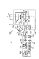
- FIG. 1 is a diagram illustrating the configuration of the microscope system 1.
- FIG. 2 is a diagram illustrating the configuration of the microscope 100.
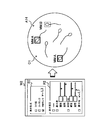
- FIG. 3 is a diagram illustrating the configuration of the operation unit of the input device 50.
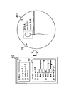
- FIG. 4 is a diagram illustrating the configuration of the image processing device 200.
- the microscope system 1 is a system for observing a sample by looking through the eyepiece 101.
- the microscope system 1 is an inverted microscope system provided with a transmission illumination system 120 used for microinsemination, particularly sperm sorting, and is used by, for example, an embryo culture technician.
- the sample to be observed by the microscope system 1 is a sperm suspension containing sperm contained in a petri dish or the like during sperm sorting work.
- the microscope system 1 includes at least a microscope 100, a photographing device 143, a projection device 153 which is an example of a superimposing device, and an image processing device 200.
- the microscope system 1 superimposes an auxiliary image on the optical image by projecting the auxiliary image on the image plane on which the optical image of the sample is formed by the optical system of the microscope 100 by using the projection device 153.
- the auxiliary image contains information that contributes to sperm separation (hereinafter referred to as auxiliary information).
- the auxiliary image is created by the image processing device 200 based on the captured image of the sample captured by the imaging device 143.
- the embryo culture person of the microscope system 1 who looks into the eyepiece 101 and observes the sample can obtain information that contributes to sperm selection without taking his eyes off the eyepiece 101, so that good sperm can be shortened. It is possible to accurately identify and collect by time. Therefore, according to the microscope system 1, it is possible to support the sperm sorting work of the embryo cultivator.
- the microscope system 1 includes a microscope 100 including an imaging device 143 and a projection device 153, and an image processing device 200. Further, the microscope system 1 includes a microscope controller 10, a display device 30, a plurality of input devices (input device 40, input device 50, input device 60, input device 70), and an identification device 80. Further, the microscope system 1 is connected to a database server 20 in which various data are stored.
- the microscope 100 is an inverted microscope provided with an eyepiece 101, and as shown in FIG. 1, the microscope main body 110, a plurality of objective lenses 102 attached to the microscope main body 110, a stage 111, a transmission illumination system 120, and a transmission illumination system 120.
- the eyepiece tube 170 is provided.
- the microscope 100 is provided with a modulation element for visualizing an unstained sample such as a sperm or an egg in each of the illumination optical path and the observation optical path.
- Users such as embryo culture specialists use the microscope 100 to perform four microscopy methods: bright field (BF) observation, polarization (PO) observation, differential interference contrast (DIC) observation, and modulation contrast (MC) observation. Can be observed.
- the modulated contrast observation is also referred to as relief contrast (RC) observation.
- the plurality of objective lenses 102 are attached to the revolver 112. As shown in FIG. 2, the plurality of objective lenses 102 include an objective lens 102a for BF observation, an objective lens 102b for PO observation and DIC observation, and an objective lens 102c for MC observation. Further, the objective lens 102c includes a modulator 104.
- the modulator 104 includes three regions having different transmittances (for example, a region having a transmittance of about 100%, a region having a transmittance of about 5%, and a region having a transmittance of about 0%).
- the plurality of objective lenses 102 may include a plurality of objective lenses having different magnifications for each microscopy method.
- a 4x objective lens for BF observation a 10x, 20x, 40x objective lens for MC observation, a 20x objective lens for PO observation, and a 60x objective lens for DIC observation are included. Will be described as an example.
- the revolver 112 is a switching device for switching objective lenses arranged on an optical path among a plurality of objective lenses 102.
- the revolver 112 switches the objective lens arranged on the optical path according to the microscopy and the observation magnification.
- the objective lens arranged on the optical path by the revolver 112 guides the transmitted light transmitted through the sample to the eyepiece 101.
- the sample contained in the container is placed on the stage 111.
- the container is, for example, a petri dish, and the sample contains germ cells such as sperm and eggs.
- the stage 111 moves in the direction of the optical axis of the objective lens 102 arranged on the optical path and in the direction orthogonal to the optical axis of the objective lens 102.
- the stage 111 may be a manual stage or an electric stage.
- the transmission illumination system 120 illuminates the sample placed on the stage 111 from above the stage 111.
- the transmission illumination system 120 includes a light source 121 and a universal capacitor 122.
- the light source 121 may be, for example, an LED (Light Emitting Diode) light source or a lamp light source such as a halogen lamp light source.
- the universal capacitor 122 includes a polarizer 123 (first polarizing plate), a plurality of optical elements housed in the turret 124, and a capacitor lens 128.
- Polarizer 123 is used in MC observation, PO observation and DIC observation.
- the turret 124 contains a plurality of optical elements that are switched and used according to the microscopy method.
- the DIC prism 125 is used for DIC observation.
- the opening plate 126 is used for BF observation and PO observation.
- the optical element 127 is a combination of a slit plate 127a, which is a light-shielding plate on which a slit is formed, and a polarizing plate 127b (second polarizing plate) arranged so as to cover a part of the slit, and is observed by MC observation. used.
- the eyepiece tube 170 includes an eyepiece lens 101.
- the imaging lens 103 is arranged between the eyepiece lens 101 and the objective lens 102.
- the imaging lens 103 forms an optical image of the sample on the image plane IP between the eyepiece lens 101 and the imaging lens 103 based on the transmitted light.
- an auxiliary image described later is also formed on the image plane IP based on the light from the projection device 153.
- the auxiliary image is superimposed on the optical image in the image plane IP.
- the user of the microscope system 1 uses the eyepiece lens 101 to observe a virtual image of an image in which an auxiliary image is superimposed on an optical image formed on the image plane IP.
- the microscope main body 110 includes a laser assisted hatching unit 130, an imaging unit 140, and a projection unit 150. Further, as shown in FIG. 2, the microscope main body 110 includes an intermediate scaling unit 160. Further, the microscope main body 110 includes a DIC prism 105 and an analyzer 106 so as to be removable with respect to an optical path.
- the laser assisted hatching unit 130 is a laser unit arranged between the objective lens 102 and the imaging lens 103.
- the laser assisted hatching unit 130 irradiates the sample with the laser beam by introducing the laser beam between the objective lens 102 and the imaging lens 103. More specifically, the laser assisted hatching unit 130 irradiates, for example, a laser beam on a zona pellucida surrounding an embryo grown from a fertilized egg.
- the laser assisted hatching unit 130 includes a splitter 131, a scanner 133, a lens 134, and a laser 135.
- the splitter 131 is, for example, a dichroic mirror.
- the scanner 133 is, for example, a galvano scanner, and adjusts the irradiation position of the laser beam in a direction orthogonal to the optical axis of the objective lens 102.
- the lens 134 converts the laser beam into a parallel luminous flux. As a result, the laser beam is focused on the sample by the objective lens 102.
- the photographing unit 140 includes a splitter 141 and a photographing device 143 that acquires a photographed image of a sample based on transmitted light.
- the photographing unit 140 is arranged between the imaging lens 103 and the eyepiece lens 101.
- the splitter 141 is, for example, a half mirror.
- the imaging lens 103 forms an optical image of the sample on the light receiving surface of the image pickup device included in the photographing apparatus 143.
- the photographing device 143 is, for example, a digital camera, and the image sensor included in the photographing device 143 is, for example, a CCD (Charge Coupled Device) image sensor, a CMOS (Complementary Metal-Oxide-Semiconducor) image sensor, or the like.
- the image sensor detects light from the sample and converts the detected light into an electric signal by photoelectric conversion.
- the photographing unit 140 outputs the photographed image acquired by the photographing device 143 to the image processing device 200.
- the microscope system 1 is used for sperm sorting, but the details of sperm, for example, the tail part are about ⁇ 0.5 ⁇ m.
- the total magnification is 10x.
- the pitch of the pixel projected image on the object surface is 0.345 ⁇ m, and the tail portion of the sperm can also be discriminated.
- the region consisting of effective pixels has a size that fills the entire field of view.
- the projection unit 150 is arranged between the imaging lens 103 and the eyepiece lens 101. As shown in FIG. 2, the projection unit 150 includes a splitter 151, a lens 152, and a projection device 153.
- the splitter 151 is, for example, a half mirror.
- the projection device 153 projects an auxiliary image generated by the image processing device 200. More specifically, the projection device 153 causes the lens 152 to collect the light from the projection device 153 at the same position as the image plane of the imaging lens 103, that is, the image plane IP on which the optical image is formed. , The auxiliary image is projected on the optical image formed on the image plane IP on the optical path.
- the size of sperm from the head to the tail is about 60 ⁇ m, and the short side of the size of the head is about 3 ⁇ m.
- the sperm image is 1.2 mm x 0.06 mm. It becomes the size of.
- the minimum rectangle is about 1.5 mm ⁇ 0.1 mm.
- the projection magnification of the lens 152 is 1x, it is composed of light emitting elements (in the case of a single color) with a pitch of 0.05 mm or less.
- the projected projection device 153 may be used. This makes it possible to display an auxiliary image in which the user can recognize a gap of 0.1 mm.
- the projection device 153 not only fills the field of view of the eyepiece 101 having a field of view of ⁇ 22, but also projects an auxiliary image in a range having a field of view of ⁇ 23 or more, which is one size larger than that.
- a projection device 153 having an effective light emitting region corresponding to a range of a field of view of ⁇ 23 or more is used.
- sperms in the peripheral portion of the visual field that have entered the visual field from outside the visual field of the eyepiece 101 are also included in the auxiliary image. Therefore, it is possible to recognize good sperms from all sperms in the visual field including the peripheral portion of the visual field of the eyepiece 101.
- the effective pixel region of the photographing device 143 also needs to correspond to the range of the number of visual fields ⁇ 23 or more in the eyepiece.
- the intermediate scaling unit 160 is arranged between the objective lens 102 and the imaging lens 103.
- the intermediate magnification unit 160 includes a plurality of lenses (lens 161 and lens 162, lens 163), and is formed on the image plane by switching the lens arranged on the optical path between them. Change the magnification of the optical image to be made. By using the intermediate magnification unit 160, the magnification of the optical image can be changed without switching the objective lens 102 located near the sample.
- the DIC prism 105 and the analyzer 106 are arranged between the objective lens 102 and the imaging lens 103.
- the DIC prism 105 is used for DIC observation.
- Analyzer 106 is used in PO and DIC observations.
- a polarizer 123 and an optical element 127 are arranged on the illumination optical path as a modulation element (hereinafter referred to as a first modulation element) that modulates the illumination light applied to the sample.
- a modulator 104 is arranged on the observation optical path as a modulation element (hereinafter, referred to as a second modulation element) that modulates the transmitted light.
- the polarizer 123 is arranged on the illumination optical path as the first modulation element
- the analyzer 106 is arranged on the observation optical path as the second modulation element.
- the polarizer 123 and the DIC prism 125 are arranged on the illumination optical path as the first modulation element, and the analyzer 106 and the DIC prism 105 are arranged on the observation optical path as the second modulation element. .. Thereby, it is possible to visualize the unstained sample, and for example, sperm can be sorted.
- the microscope controller 10 is a device that controls the microscope 100.
- the microscope controller 10 is connected to the image processing device 200, the input device 50, and the microscope 100, and controls the microscope 100 in response to a command from the image processing device 200 or the input device 50.
- the display device 30 is, for example, a display device such as a liquid crystal display, a plasma display, an organic EL display, a CRT display, or an LED matrix panel.
- the input device 40 includes a handle 41 and a handle 42. By operating the handle 41 and the handle 42, the operation of the pipette 43 and the micromanipulator (not shown) for moving the pipette 44 is controlled. Pipette 43 and pipette 44 are used to manipulate the sample in microinsemination operations, including sperm sorting.
- the pipette 43 is, for example, a holding pipette
- the pipette 44 is, for example, an injection pipette.
- the input device 50 is a hand switch device for changing the settings related to the microscope method and the observation magnification of the microscope 100. As shown in FIG. 3, the input device 50 has, for example, six buttons (buttons 51 to 56), and the user can quickly switch the settings of the microscope 100 simply by pressing these buttons. Can be done.
- the setting of the microscope 100 is switched to the setting of BF observation (hereinafter referred to as BF4 ⁇ observation) with an observation magnification of 4 times.
- the setting of the microscope 100 is switched to the setting of MC observation (hereinafter referred to as MC10 ⁇ observation) at an observation magnification of 10 times.
- the setting of the microscope 100 is switched to the setting of MC observation (hereinafter referred to as MC20 ⁇ observation) at an observation magnification of 20 times.
- the setting of the microscope 100 is switched to the setting of MC observation (hereinafter referred to as MC40 ⁇ observation) having an observation magnification of 40 times.
- the setting of the microscope 100 is switched to the setting of PO observation (hereinafter referred to as PO20 ⁇ observation) at an observation magnification of 20 times.
- the setting of the microscope 100 is switched to the setting of DIC observation (hereinafter referred to as DIC 60 ⁇ observation) having an observation magnification of 60 times.
- the input device 60 is a keyboard.
- the input device 70 is a mouse.
- the input device 60 and the input device 70 are each connected to the image processing device 200.
- the microscope system 1 may include other input devices (not shown) such as a touch panel, a voice input device, and a foot pedal.
- the identification device 80 is a device that acquires identification information added to the sample.
- the term "added to the sample” includes, for example, the case where the identification information is attached to the container for accommodating the sample.
- the identification information is information that identifies the sample, and more specifically, for example, information that identifies the patient who provided the sample.
- the identification device 80 may be, for example, a barcode reader, an RFID (registered trademark) reader, a QR code (registered trademark) reader, or the like.
- the image processing device 200 generates an auxiliary image based on the captured image acquired by the photographing device 143.
- the generated auxiliary image is output to the projection device 153 of the microscope 100, directly or via the microscope controller 10.
- the image processing device 200 is connected to the microscope 100, the microscope controller 10, the display device 30, the input device 60, the input device 70, and the identification device 80.
- the image processing device 200 is also connected to the database server 20.
- the image processing device 200 includes an image analysis unit 210, an image generation unit 220, and a storage unit 230 as functional components related to the generation of an auxiliary image including auxiliary information that contributes to sperm selection. Twice
- the image analysis unit 210 performs image analysis including object detection for sperm for a captured image and recommendation degree estimation for estimating the recommendation degree of sperm detected by the object detection. Specifically, the image analysis unit 210 performs object detection and recommendation degree estimation using, for example, a learned model stored in the storage unit 230. Object detection and recommendation degree estimation may be performed using two or more trained models, or may be performed using a single trained algorithm. The algorithm of the trained model is not particularly limited, but for example, a deep learning model such as SSD, YOLO, or FasterR-CNN may be used.
- the image generation unit 220 generates an auxiliary image including auxiliary information that contributes to sperm selection based on the result of the image analysis of the image analysis unit 210.
- the auxiliary information includes information on the sperm recommendation level (hereinafter referred to as recommendation level information) generated based on the result of the recommendation level estimation. That is, the image generation unit 220 generates an auxiliary image including at least recommendation degree information.
- the recommendation level information may be numerical information such as DFI described later, or symbol information indicating a grade such as DFI rank and MM rank described later. Further, the recommendation degree information may be a combination of one or more numerical information and one or more symbol information.
- the recommendation degree information may include at least one or more numerical information and at least one or more symbolic information.
- the auxiliary information may further include information regarding the sperm position (hereinafter referred to as position information) generated based on the result of object detection. That is, the image generation unit 220 may generate an auxiliary image including position information in addition to the recommendation degree information.
- the recommendation degree estimation performed by the image analysis unit 210 may include an integrity estimation for estimating the DNA integrity of the sperm detected by the object detection.
- the integrity information may include integrity information regarding sperm DNA integrity generated based on the results of integrity estimation. It is desirable that the integrity information includes at least one of DFI and a rank corresponding to DFI, which will be described later.
- the DFI or DFI rank preferably includes at least two of the latest information, average information, and maximum information.
- the recommendation level estimation performed by the image analysis unit 210 may include quality estimation for estimating the quality of at least one of sperm morphology and motility detected by object detection. In that case, the recommendation level information may include quality information regarding at least one of the morphological quality of sperm and the quality of sperm motility generated based on the result of quality estimation.
- Non-Patent Document 1 Wang, Y. et al., Prediction of DNA Integrity from Morphological Parameters Using a Single-Sperm DNA Fragmentation Index 20 SCDNA, VSC. There is a correlation between completeness and sperm morphology.
- the completeness estimation performed by the image analysis unit 210 is performed using a trained model in which the DNA completeness of sperm with respect to the sperm morphology extracted from the image is learned by utilizing this fact.
- the recommendation level information included in the auxiliary image may have an aspect according to the recommendation level estimated by the recommendation level estimation. More specifically, for example, it may have a color corresponding to the recommendation level estimated by the recommendation level estimation. Further, the position information included in the auxiliary image may also have an aspect corresponding to the recommendation level estimated by the recommendation level estimation, as in the recommendation level information, and may be, for example, the recommendation level estimated by the recommendation level estimation. It may have a corresponding color.
- the storage unit 230 stores the trained model used in the image analysis performed by the image generation unit 220.
- the storage unit 230 stores a learned model for detecting an object targeting sperm, and the image generation unit 220 performs object detection using the learned model stored in the storage unit 230. Further, for example, when the image generation unit 220 generates the completeness information, the storage unit 230 stores a learned model in which the DNA completeness of the sperm with respect to the sperm morphology is learned.
- the image generation unit 220 performs integrity estimation using the trained model stored in the storage unit 230.
- the storage unit 230 stores a learned model that learns the quality of sperm with respect to at least one of sperm morphology and sperm motility. ing.
- the image generation unit 220 performs quality estimation using the trained model stored in the storage unit 230.
- the object detection, completeness estimation, and quality estimation may be performed using a single trained model stored in the storage unit 230, and two or more trained models stored in the storage unit 230 may be used. It may be done using a model.
- the image processing device 200 may be a general-purpose computer or a dedicated computer.
- the image processing device 200 is not particularly limited to this configuration, but may have, for example, a physical configuration as shown in FIG.
- the image processing device 200 may include a processor 201, a storage device 202, an input interface (I / F) 203, an output interface (I / F) 204, and a communication device 205. , They may be connected to each other by bus 206.
- the processor 201 may include hardware, which may include, for example, at least one of a circuit for processing digital signals and a circuit for processing analog signals.
- Processor 201 may include, for example, one or more circuit devices (eg, ICs) or one or more circuit elements (eg, resistors, capacitors) on a circuit board.
- the processor 201 may be a CPU (central processing unit). Further, various types of processors including GPU (Graphics processing unit) and DSP (Digital Signal Processor) may be used for the processor 201.
- the processor 201 may be a hardware circuit having an ASIC (Application Specific Integrated Circuit) or an FPGA (Field-Programmable Gate Array).
- the processor 201 can include an amplifier circuit, a filter circuit, and the like for processing an analog signal.
- the processor 201 functions as the image analysis unit 210 and the image generation unit 220 described above by executing the program stored in the storage device 202.
- the storage device 202 may include a memory and / or other storage device.
- the memory may be, for example, a random access memory (RAM).
- the memory may be a semiconductor memory such as SRAM (Static Random Access Memory) or DRAM (Dynamic Random Access Memory).
- the storage device 202 may include, for example, a register, a magnetic storage device such as a hard disk device, an optical storage device such as an optical disk device, an internal or external hard disk drive, a solid state storage device, a CD-ROM, a DVD, or other optical or magnetic. It may be a disk storage device or another storage device.
- the storage device 202 stores programs, trained models, and other data executed by the processor 201, and functions as the storage unit 230 described above.
- the storage device 202 is an example of a non-temporary computer-readable storage medium.
- the input I / F 203 is connected to an input device operated by a user of the microscope system 1 (for example, an embryo culture technician), receives an operation signal corresponding to the operation of the input device, and outputs the operation signal to the processor 201.
- a user of the microscope system 1 for example, an embryo culture technician
- the output I / F 204 is connected to the display device 30.
- the output I / F 204 may be further connected to an audio output device such as a speaker that outputs audio, a light emitting device such as a lamp or light that outputs light, or a vibrating device such as a vibrator that outputs vibration, which is not shown. ..
- the communication device 205 is a device that exchanges data with the microscope 100 and other devices.
- the communication device 205 may be a communication device that exchanges data by wire, or may be a communication device that exchanges data wirelessly.
- the program or learned model stored in the storage device 202 may be acquired by the communication device 205 from another device via the Internet.
- FIG. 5 is a flowchart showing an example of the procedure for creating a learning data set.
- FIG. 6 is a flowchart showing an example of the learning process.
- the procedure for constructing the trained model stored in the storage unit 230 will be described with reference to FIGS. 5 and 6 by taking as an example the case of constructing the trained model for estimating the DNA integrity.
- the preparation procedure shown in FIG. 5 may be performed by the microscope system 1 or may be performed by another device or system. Further, the learning process shown in FIG. 6 may be performed by a computer different from the image processing device 200, and the image processing device 200 may acquire the completed trained model via a network or a recording medium. .. In the following, a case where the microscope system 1 performs the creation procedure shown in FIG. 5 and the image processing apparatus 200 performs the learning process shown in FIG. 6 will be described as an example.
- the microscope system 1 first captures a moving image of sperm (step S1).
- the operator observes the sperm suspension using the microscope system 1, for example, at a magnification of 40, and picks up the sperms contained in the sperm suspension one by one.
- the worker is, for example, an embryo culture person.
- the microscope system 1 captures a moving image of each sperm picked up by, for example, the imaging unit 140.
- the magnification at this time is, for example, 40 times, 60 times, and the like.
- the operator rotates the sperm using the tip of a pipette or the like. As a result, the microscope system 1 photographs the entire circumference of the sperm head and neck.
- the microscope system 1 stains the sperm whose moving image has been taken and then takes a picture again (step S2).
- the operator fixes each of the spermatozoa imaged in step S1 at a position in the assigned container, and then stains the sperm in the container with a dye that labels DNA damage.
- the operator observes the sperm in the stained container by a fluorescence observation method, and further, photographs the sperm with the microscope system 1 to acquire a stained image of the sperm.
- the microscope system 1 calculates the DNA fragmentation index (DFI: DNA fragmentation index) of each sperm from the stained image acquired in step S2 (step S3).
- DFI is an index of DNA integrity, and the smaller the value, the better.
- the specific calculation method of DFI is not particularly limited, but for example, Non-Patent Document 2 (McCallum, C. et al., Deep learning-based selection of human sperm with high DNA integrity, Communications 2, Communications Biol). As described in 2019)), it may be calculated using an AO (Acridine Orange) test.
- the microscope system 1 labels the unstained image of sperm extracted from the moving image acquired in step S1 with the DFI calculated in step S3 (step S4).
- the microscope system 1 assigns DFI to each frame image (unstained image) of the moving image, so that the unstained image of the sperm and the DFI of the sperm are stored in association with each other.
- the association between the moving image taken in step S1 and the DFI calculated in step S3 can be performed by managing the ID assigned to the moving image and the position in the container.
- the learning process is performed by using a large number of unstained images labeled according to the procedure of FIG. 5 as a learning data set.
- the image processing apparatus 200 first acquires the created training data set (step S11).
- the image processing apparatus 200 trains the sperm into a model that estimates the integrity of the DNA (step S12).
- the image processing apparatus 200 trains, verifies, and tests the model using the training data set.
- the learning data set acquired in step S11 may be divided into training data / verification data and test data in step S12. In that case, it is desirable that the training and validation data be used for both training and validation using cross-validation.
- the training data is data used for training the model
- the verification data is data used for verifying the model.
- the test data is data used for testing the model.
- the image processing device 200 repeats the above processing until the model clears the test, and when the processing is cleared, that is, when learning is completed (step S13YES), the processing of FIG. 6 is completed.
- the obtained trained model is stored in the storage unit 230 of the image processing device 200.
- this trained model has a label indicating DNA completeness calculated from a non-stained image obtained by photographing the sperm before staining and a stained image obtained by photographing the sperm after staining attached to the unstained image.
- FIG. 7 is a flowchart showing another example of the procedure for creating the learning data set.
- FIG. 8 is a diagram showing an example of a screen for creating a learning data set.
- the learning of a model for estimating DNA completeness for sperm has been described as an example, but quality estimation for estimating the morphological quality of sperm and the quality of sperm motility have been described.
- the training data set may be created by the creation procedure shown in FIG. 7 instead of the creation procedure shown in FIG.
- the procedure for constructing the trained model stored in the storage unit 230 when constructing a trained model that estimates the quality of at least one of sperm morphology and motility. Will be described as an example.
- the microscope system 1 first captures a moving image or a still image of sperm (step S21).
- the operator observes the sperm suspension using the microscope system 1 at a magnification of, for example, 20 times, and photographs the sperm in the sperm suspension as a moving image or a still image with the photographing unit 140.
- the microscope system 1 cuts out an image of the sperm portion from the captured image (moving image or still image) and displays it side by side (step S22).
- the microscope system 1 reads out the moving image or still image taken in step S21, cuts out an image of the sperm portion from the moving image or still image, and displays them side by side on the display device 30 as shown in FIG.
- the operator evaluates the morphological quality of sperm and the quality of sperm motility from the images of sperm displayed side by side. Therefore, it is desirable that the worker is a skilled embryo cultivator with a high fertilization success rate.
- the image obtained by cutting out the sperm portion will be referred to as a reference image.
- the microscope system 1 labels each reference image with a quality evaluation by the embryo cultivator (step S23).
- the microscope system 1 assigns a quality rank to each sperm reference image (unstained image) to associate and store the unstained sperm image and the sperm quality.
- the image (T1, T10, T14, %) Clicked with the button B1 on the window W1 selected is saved in association with the label of rank A indicating the quality. .. Further, the image (T2, T3, T6, T8, T9, T11, T15 %) Clicked with the button B2 selected is saved in association with the label of rank B indicating the quality. Further, the image (T4, T5, T13, T16 %) Clicked with the button B3 selected is saved in association with the label of rank C indicating the quality. Further, the image (T7, T12 ...) Clicked with the button B4 selected is saved in association with the label of rank D indicating the quality. Note that rank A is assigned to the image evaluated with the highest quality, and rank D is assigned to the image evaluated with the lowest quality. That is, ranks A, B, C, and D indicate that the quality deteriorates in this order.
- the learning process shown in FIG. 6 may be performed by using a large number of unstained images labeled in the procedure of FIG. 7 as a learning data set.
- the obtained trained model is stored in the storage unit 230 of the image processing device 200.
- this trained model contains a data set including a reference image obtained by photographing the sperm and a label attached to the reference image indicating the quality of the sperm evaluated by the embryo culture specialist based on the reference image. It is a trained model whose parameters are adjusted by supervised learning used as training data.
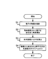
- FIG. 9 is a flowchart showing an example of sperm sorting support processing.
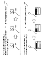
- FIG. 10 is a flowchart showing an example of the auxiliary image generation process.
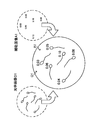
- FIG. 11 is a diagram for explaining image processing on a captured image.
- FIG. 12 is a diagram for explaining an image projected on the image plane.
- the microscope system 1 first projects an optical image onto the image plane (step S31).
- the optical system including the objective lens 102 and the imaging lens 103 is placed on the optical path of the microscope 100, for example, based on the light from the sperm suspension which is a sample placed on the stage of the microscope 100.
- An optical image O1 of a sperm suspension is formed as shown in.
- the microscope system 1 acquires a captured image at the same time as step S31 (step S32).
- the photographing device 143 acquires a photographed image of the sperm suspension based on the light from the sperm suspension, and outputs the photographed image to the image processing device 200.
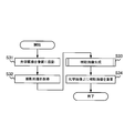
- the microscope system 1 performs the auxiliary image generation process shown in FIG. 10 (step S33).
- the image processing device 200 first detects sperm from the captured image (step S41).
- the image analysis unit 210 detects an object targeting sperm by inputting the captured image M as an input image into the trained model, for example, as shown in FIG.
- the image analysis unit 210 may detect sperms by classifying them according to the quality of sperm morphology or motility.
- FIG. 11 shows how sperms detected by object detection are classified from rank A to rank C. In this case, it may be considered that the object detection in step S41 also serves as the recommendation degree estimation in step S42, which will be described later.
- the image processing device 200 estimates the degree of recommendation from the image of the sperm detected in step S41 (step S42).
- the image analysis unit 210 estimates the sperm recommendation level by inputting the detected sperm images (images M1 to M6) into the trained model as input images. do.
- FIG. 11 shows an example in which DFI was calculated as a recommendation level.
- the image processing device 200 After that, the image processing device 200 generates an auxiliary image including sperm recommendation degree information (step S43).
- the image generation unit 220 generates recommendation degree information regarding the sperm recommendation degree based on the result of the recommendation degree estimation in step S42, and for example, an auxiliary image including the recommendation degree information as shown in FIG. Generate A1.
- the microscope system 1 When the auxiliary image generation process is completed, the microscope system 1 superimposes the auxiliary image on the optical image (step S34), and ends the process shown in FIG.
- the projection device 153 projects the auxiliary image A1 generated in step S33 on the image plane IP on which the optical image O1 is formed, whereby the auxiliary image A1 is projected on the optical image O1 as shown in FIG. Are superimposed.
- the embryo culture person who is the user of the microscope system 1 looks into the eyepiece 101 and sees the optical image O1 containing sperm and the auxiliary image A1 containing auxiliary information contributing to sperm selection as shown in FIG. You can sort sperm while looking at the image on which. Therefore, according to the microscope system 1, it is possible to support the sperm sorting work by the embryo cultivator.
- the auxiliary information includes sperm recommendation level information, it becomes easy to judge good sperm, so that sperm sorting work can be performed quickly in a short time.
- the recommendation level information includes the completeness information regarding the DNA completeness of the sperm, the sperm can be selected in consideration of the presence or absence of DNA damage which is difficult to judge from the optical image O1 alone. Therefore, according to the microscope system 1, the embryo culture technician can select good sperms with higher reliability than the conventional judgment based on morphology and motility.
- FIG. 13 is a flowchart showing an example of the ICSI procedure.
- FIG. 14 is a diagram illustrating the configuration of a drop formed as a sample 300 in a petri dish 310.
- FIG. 15 is a flowchart showing an example of a sperm sorting procedure.
- FIG. 16 is a flowchart showing another example of the auxiliary image generation process.
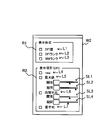
- FIG. 17 is a diagram for explaining a configuration example of the auxiliary image setting window.
- 18 to 24 are diagrams illustrating the relationship between the auxiliary image setting and the image seen from the eyepiece 101, respectively.
- FIGS. 13 to 24 specific utilization of the sperm sorting support method performed by the microscope system 1 in ICSI will be described with reference to FIGS. 13 to 24.
- the user prepares a sample (step S51).
- a sample 300 containing a plurality of drops in the petri dish 310 and arranges the sample 300 on the stage 111.
- Drop 301 is a cleaning drop and is used for cleaning pipettes.
- the drop 302 is a sperm floating drop, for example, a sperm suspension added dropwise to a PVP solution.
- the drop 303 is an egg manipulation drop, for example, an egg is put in an m-HTF solution.
- the m-HTF solution is a Hepps-containing HTF solution to which 10% serum is added. These drops are covered with mineral oil.
- the user sets up the microscope system 1 (step S52).
- the user presses the button 51 of the input device 50 to switch the setting of the microscope system 1 to BF4 ⁇ observation.
- the input device 40 is operated to adjust the positions of the pipette 43 and the pipette 44 to focus on the pipette 43 and the pipette 44.
- the stage 111 is moved to wash the pipette 43 and the pipette 44 with the drop 301 (washing drop).
- the user confirms the growth state of the egg (egg cell) in the drop 303 (drop for egg operation) (step S53).
- the user presses the button 53 of the input device 50 to switch the setting of the microscope system 1 to MC20 ⁇ observation.
- Eggs are selected by observing the morphology of the eggs with MC20 ⁇ observation.
- the button 55 of the input device 50 may be pressed to switch the setting of the microscope system 1 to PO20 ⁇ observation.
- the maturity of the egg may be determined, and the egg may be further selected.
- step S54 the user selects the sperm according to the procedure shown in FIG. 15 (step S54).
- the stage 111 is moved to move the observation position to the drop 302 (sperm floating drop), and the sperm is focused by MC20 ⁇ observation (step S61).
- step S62 the user selects good sperms suitable for fertilization by MC20 ⁇ observation.
- an embryo culture person judges the quality of sperm based on the morphology and motility of sperm observed in an optical image, and selects good sperm based on the judgment.
- the criteria for determining good sperm are not always clear. For this reason, sperms are often selected based on the experience and intuition of the embryo cultivator, and as a result, the judgment differs depending on the embryo cultivator. This was the cause of the difference in fertilization success rate among embryo culture specialists.
- the microscope system 1 supports the sperm sorting work of the embryo cultivator by superimposing an auxiliary image including auxiliary information contributing to sperm sorting on the optical image.
- step S62 the microscope system 1 performs the auxiliary image generation process shown in FIG. 16, and as a result, the generated auxiliary image is projected onto the image plane.
- the image processing device 200 detects sperm from the captured image of the drop 302 (sperm floating drop) captured by the imaging device 143, and generates position information regarding the position of the detected sperm (step S71).
- object detection for sperm is performed using the trained model.
- the image processing device 200 estimates the degree of recommendation from the sperm image detected in the captured image (step S72).
- recommendation degree estimation such as completeness estimation and quality estimation is performed using the trained model.
- the DFI is estimated for each sperm by the completeness estimation, and the sperm morphology and motility rank (hereinafter referred to as MM rank) are determined for each sperm by the quality estimation.
- MM rank sperm morphology and motility rank
- the image processing device 200 generates recommendation degree information according to the setting by the user (step S73).
- the image processing device 200 is set in step S72 according to the settings previously made by the user on the window W2 shown in FIG. 17 displayed on the display device 30 by using the input device 60 and the input device 70.
- Recommendation level information is generated from the obtained estimation results.
- the window W2 is an auxiliary image setting window for setting recommendation level information included in the auxiliary image, and includes an area R1 for setting a display format and an area R2 for setting display items.
- a list box L1 for selecting a DFI value As shown in FIG. 17, in the area R1, as a display format of the recommendation level, a list box L1 for selecting a DFI value, a list box L2 for selecting a DFI rank, and an MM rank are selected.
- the list box L3 is included.
- the DFI value is the DFI itself, and the DFI rank is obtained by dividing the DFI into a predetermined range and assigning a rank to each range.
- the DFI value can be included as the recommendation level information in the auxiliary image.
- the DFI rank can be included as the recommendation degree information in the auxiliary image.
- the MM rank can be included as the recommendation degree information in the auxiliary image. It is also possible to select a plurality of list boxes L3 from the list box L1, and in that case, information in a plurality of display formats can be included as recommendation degree information.
- a list box L6 for selecting an average and a list box L7 for selecting a circumference average are included.
- Raw is DFI estimated from the latest captured image.
- the maximum value is the maximum value of DFI estimated within the period set by the slider SL2.
- the threshold value set by the slider SL1 is the upper limit of the maximum value included in the recommendation degree information.
- the time average is the average value of DFI estimated within the period set by the slider SL4.
- the threshold value set by the slider SL3 is the upper limit of the average value included in the recommendation degree information.
- the image processing device 200 When the recommendation level information is generated, the image processing device 200 generates an auxiliary image including the recommendation level information and the position information in a mode corresponding to the recommendation level (step S74).
- the image processing apparatus 200 may generate, for example, an auxiliary image including recommendation degree information and position information in colors corresponding to the recommendation degree. More specifically, if the position information is generated as a bounding box surrounding the sperm, the thickness and line type of the lines constituting the bounding box included in the auxiliary image may be different depending on the degree of recommendation. ..
- the microscope system 1 performs the auxiliary image generation process shown in FIG. 16 and projects the generated auxiliary image onto the image plane, so that in step S62, the user can use the optical image O1 as shown in FIG. Sperm can be selected while looking at the superimposed auxiliary image A11.
- FIG. 18 shows an example of an image projected in the field of view of the eyepiece 101 when the DFI value is selected as the display format and the maximum value is selected as the display item.
- the displayed DFI is the maximum value for the last 2 seconds and is limited to 0.05 or less by the threshold setting.
- the sperm selection in step S62 selects good sperms from a large number of sperms contained in the sperm suspension, and it is expected that many sperms are also contained in the visual field.
- the threshold setting by the slider SL1 is effective.
- the threshold value By setting the threshold value, only the recommendation level information of sperms having DFI below the threshold value (here, the maximum value of DFI) can be projected, so that the amount of information superimposed on the optical image O1 is appropriately limited. be able to.
- innumerable sperm recommendation level information is projected in the field of view, and the visibility of the optical image (sperm) is reduced, and there are too many pieces of information to make it difficult to understand the necessary information. It can be avoided.
- by limiting the amount of information using a threshold value it becomes possible for the user to concentrate on only the sperms with high evaluation and observe them.
- step S62 since the sperm freely move around in the sperm suspension, the direction and shape of the sperm in the captured image change from moment to moment. Therefore, it is expected that the estimated DFI will change from moment to moment even for the same sperm.
- the period setting by the slider SL2 is effective. By setting the period, it is possible to extract or reconstruct necessary information from a large number of estimation results obtained within the set period and project it. This makes it possible to provide the user with the recommendation level of sperm without being influenced by the temporary estimation result at a specific time.
- the position information is formed as a bounding box surrounding the sperm head. As shown in FIG. 18, location information may be formed to identify a major portion of sperm rather than the entire sperm. Such display of position information is also particularly suitable in step S62, where a large number of sperms are expected to be detected.
- FIG. 18 shows an example in which one recommendation degree information is superimposed on one sperm
- a plurality of recommendation degree information may be superimposed.
- FIG. 19 shows an example of an image projected in the field of view of the eyepiece 101 when the DFI value is selected as the display format and raw and the maximum value are selected as the display items. ..
- the displayed DFI is the latest value (raw) and the maximum value for the last 2 seconds, and is limited to 0.05 or less by the threshold setting.
- the auxiliary image A13 including a plurality of information for each sperm may be superimposed on the optical image O1.
- the user can hit the sperm to be observed in the DFI rank and observe the sperm while checking the DFI value, so that the sperm can be efficiently selected.
- FIG. 20 shows an example of an image projected in the field of view of the eyepiece 101 when the DFI value and the DFI rank are selected as the display format and the time average is selected as the display item. There is.
- the DFI displayed together with the DFI rank is the time average value for the last 1 second, and is limited to 0.05 or less by the threshold setting.
- FIGS. 18 to 20 an example in which information on DNA completeness is superimposed as recommendation degree information is shown, but as shown in FIG. 21, the MM rank based on the sperm morphology and motility that has been conventionally performed is shown.
- the auxiliary image A14 including the above as the recommendation degree information may be superimposed on the optical image O1.
- the auxiliary image A15 including both the MM rank and the information on the DNA integrity (here, the DFI value) as the recommendation degree information may be superimposed on the optical image O1.
- the DFI value and the MM rank are selected as the display format and the time average is selected as the display item.
- the DFI displayed together with the MM rank is the time average value for the last 1 second, and is limited to 0.05 or less by the threshold setting.
- step S62 by superimposing the auxiliary image on the optical image O1, the user can easily recognize the sperm of particular interest by the auxiliary image, so that good sperm can be selected. Therefore, the number of sperms confirmed by the user can be significantly reduced. Therefore, the sperm sorting work becomes easy and the sperm sorting can be performed in a short time, so that the burden of the sorting work is greatly reduced.
- step S62 When good sperms are selected in step S62, the user injures the tail of the good sperms by RC20 ⁇ observation and immobilizes the good sperms (step S63). Here, the user immobilizes the good sperm by rubbing the tail of the good sperm against the bottom surface of the petri dish 310 with a pipette.
- the user observes the morphology of the immobilized good sperm in more detail and further selects the good sperm (step S64).
- the user for example, presses the button 54 of the input device 50 to switch the setting of the microscope system 1 to MC40 ⁇ observation. After that, the user selects better sperm by MC40 ⁇ observation.
- the microscope system 1 performs the auxiliary image generation process shown in FIG. 16 as in step S64, and as a result, the generated auxiliary image is projected onto the image plane to perform the sperm separation work of the embryo incubator. Support.
- the microscope system 1 performs the auxiliary image generation process shown in FIG. 16 and projects the generated auxiliary image onto the image plane, so that in step S64, the user can use the optical image O2 as shown in FIG. Sperm can be selected while looking at the superimposed auxiliary image A21.
- FIG. 23 shows an example of an image projected in the field of view of the eyepiece 101 when the DFI value and the DFI rank are selected as the display format and raw and the circumferential average are selected as the display items. Has been done.
- the sperm selection in step S64 is performed in a state where a specific sperm is immobilized, and it is expected that a single sperm is included in the visual field.
- the user can observe the sperm from any direction by adjusting the direction of the sperm with the tip of the pipette, and by rolling the sperm with the tip of the pipette, the head of the sperm and the sperm can be observed. The entire circumference of the neck can be photographed. Therefore, as shown in FIG. 23, the calculation setting of the peripheral average by selecting the list box L7 is effective. By calculating the perimeter average, it is possible to provide the user with highly reliable DNA integrity regardless of the imaging direction.
- step S64 the image processing apparatus 200 calculates the sperm rotation amount, and when the sperm rotation amount is insufficient (for example, the rotation amount is less than 360 °), as shown in FIG. 24, the sperm rotation amount is insufficient.
- the auxiliary image A22 including the information to be notified may be generated, and the projection device 153 may superimpose the auxiliary image A22 on the optical image O2. That is, the image analysis performed by the image analysis unit 210 may include a process of estimating the recommended operation in addition to the object detection and the recommendation degree estimation, and the image analysis unit 210 is selecting sperm based on the captured image.
- the notification of the recommended operation may be notified by voice, light, vibration, or the like instead of or in addition to the notification by using the auxiliary image so as to be visible. That is, the notification device may be a projection device 153, or may be a speaker, a lamp, a vibrator, or the like (not shown).
- step S65 When the selection of good sperm by MC40 ⁇ observation is completed, the user further observes the head of the good sperm in detail and further selects the good sperm according to the size of the blank present in the head (step S65). ).
- the user selects good spermatozoa with small blanks as better spermatozoa by DIC60 ⁇ observation.
- step S65 may be performed under MC40 ⁇ observation. In this case, the user selects good sperms by recognizing the bright spots generated on the head as blanks.
- the user takes the selected good sperm into the pipette 44, which is an injection pipette, moves the observation position to the drop 303 (drop for egg manipulation) (step S66), and performs a series of sperm selection shown in FIG. End the procedure of.
- the user confirms the position of the mitotic spindle in preparation for good sperm injection (step S55).
- the user observes the egg selected in step S53 existing in the drop 303 and confirms the position of the spindle of the egg.
- the user presses, for example, the button 55 of the input device 50 to switch the setting of the microscope system 1 to PO20 ⁇ observation.
- the user changes the orientation of the spindle by operating the pipette 43, which is a holding pipette, so that the spindle of the egg visualized by PO20 ⁇ observation is located in the direction of 12 o'clock or 6 o'clock. This is to avoid damaging the mitotic spindle by the pipette thrust into the egg from the 3 o'clock or 9 o'clock direction in step S56, which will be described later.
- the user injects sperm into the egg (step S56) and ends ICSI.
- the user presses the button 53 of the input device 50 to switch the setting of the microscope system 1 to MC20 ⁇ observation.
- the user fixes the egg whose orientation was adjusted in step S55 with the pipette 43, which is a holding pipette, and pierces the pipette 44, which is an injection pipette, by observing MC20 ⁇ . Then, good sperm is injected into the egg from the pipette 44.
- the user When the series of ICSI procedures shown in FIG. 13 is completed, the user returns the sperm-injected egg to the incubator and incubates it. Further, the user may operate the processing device 200 by using the input device 60 and the input device 70, and save the information obtained by ICSI in the database server 20. For example, image data of sperm-injected eggs, image data of selected good sperms, ICSI working hours, sperm and egg patient information (maternal clinical data, test results of sperm-containing semen, etc.), Data of sperm and egg culture solutions (eg, type, concentration, PH, etc.) may be associated and stored in the database server 20.
- an auxiliary image contributing to sperm separation is projected on the image plane in ICSI.
- the size of sperm is about 60 ⁇ m, and an objective lens of at least 20 times is used to distinguish good sperm.
- the number of fields of view of an inverted microscope is about 22, so the actual field of view is about ⁇ 1 mm.
- the work of selecting sperms that move around freely in this region of the actual field of view ⁇ 1 mm is a very difficult work.
- sperms presumed to be good sperms have high motility, and ICSI work needs to be performed in a short time. Therefore, in sperm sorting work, the morphology of sperms that move relatively quickly is quickly observed.
- FIG. 25 is a diagram showing the configuration of the microscope 400.
- the projection device 153 arranged on the optical path branched from the optical path between the objective lens 102 and the eyepiece lens 101 is illustrated, but the device for superimposing the auxiliary image is an objective as shown in FIG. It may be arranged on the optical path between the lens 102 and the eyepiece 101.
- the microscope 400 differs from the microscope 100 in that instead of the projection unit 150, a display device 401 is included on an image plane on which an optical image is formed.
- the display device 401 is a transmissive image display device, and is an example of a superimposition device that superimposes an auxiliary image on an optical image by displaying the auxiliary image directly on the image plane. Even when the microscope 400 is used, it is possible to support the sperm sorting of the embryo incubator as in the case of using the microscope 100.
- FIG. 26 is a diagram showing the configuration of the microscope system 2.
- the imaging device 143 and the projection device 153 are provided in the microscope 100, and the image processing device 200 independent of the microscope 100 exchanges data with the imaging device 143 and the projection device 153 to obtain an optical image of the auxiliary image.
- the photographing apparatus, the projection apparatus, and the image processing apparatus may be integrally configured as shown in FIG.
- the projection unit 600 mounted between the microscope main body 510 of the microscope 500 and the lens barrel 520 includes an imaging device 143, a projection device 153, and an image processing device (image analysis unit 210, image generation unit 220, A storage unit 230) may be provided.
- an image processing device image analysis unit 210, image generation unit 220, A storage unit 230
- the DFI value, DFI rank, and MM rank are illustrated as the recommendation level information included in the auxiliary image, but the recommendation level information is not limited to these.
- the recommendation level information may be a sperm quality determination result.
- object detection and recommendation degree estimation may be performed using a trained model that has learned the quality of sperm.
- FIG. 27 is a diagram showing still another example of the relationship between the auxiliary image setting and the image seen from the eyepiece lens 101. As shown in FIG. 27, by selecting the list box L8 provided in the area R1 for selecting the recommended display format, the auxiliary image A16 including the quality determination result may be superimposed on the optical image O1. ..
- the auxiliary image A16 may include, for example, a bounding box A16a that encloses the sperm that is most frequently judged as "good” by the quality judgment performed for each frame.
- the sperm having the largest value calculated by multiplying the number of times determined to be "good” by the value of VSL (linear velocity) may be surrounded by the bounding box A16a.
- VSL linear velocity
- the sperm movement locus A16b surrounded by the bounding box A16a may be included in the auxiliary image A16.
- FIG. 28 is a diagram showing still another example of the relationship between the auxiliary image setting and the image seen from the eyepiece lens 101. 29 and 30 are diagrams for explaining the merits of the bar display. As shown in FIG. 28, by selecting the list box L8 provided in the area R1 for selecting the recommended display format, the auxiliary image A17 including the bar indicating the pass / fail judgment result is superimposed on the optical image O3. You may. That is, the recommendation level may be presented to the user by displaying a bar.
- the three bars showing the pass / fail judgment results shown in FIG. 28 show the probabilities of each classification of "good”, “bad”, and “undecidable” output from the trained model by length. be.
- FIG. 31 is a diagram for explaining a desirable change example regarding the display format of the auxiliary image.
- the simple display using the bounding box and the bar display have merits, and by using them properly according to the situation, it is possible to efficiently and surely select good sperm.
- the quality of each sperm is determined on the optical image O1 as shown in FIG.
- Auxiliary image A17 including a bounding box in which the result is expressed in color may be superimposed.
- the immobilized sperm quality determination result is displayed on the optical image O2.
- Auxiliary image A22 represented by using a plurality of bars may be superimposed.
Abstract
A microscope system 1 comprises: a microscope 100; an imaging device 143 for acquiring a captured image of a material that includes sperm placed on a stage 111 of the microscope 100; an image processing device 200 for generating an auxiliary image including auxiliary information that contributes to sperm sorting, on the basis of the captured image acquired by the imaging device 143; and a projection device 153 which is a superimposing device for superimposing the auxiliary image generated by the image processing device 200 on an optical image of a sample, formed on an image plane in the optical path of the microscope 100.
Description
本明細書の開示は、顕微鏡システム、投影ユニット、及び、精子選別支援方法に関する。
The disclosure of this specification relates to a microscope system, a projection unit, and a sperm sorting support method.
晩婚化・晩産化が進む現在、不妊治療を受ける患者の数は年々増加しており、生殖補助医療(ART:Assisted Reproductive Technology)の需要もますます高まっている。
With the progress of late marriage and late childbirth, the number of patients receiving infertility treatment is increasing year by year, and the demand for assisted reproductive technology (ART) is also increasing.
ARTは、体外受精(IVF:In vitro fertilization)や顕微授精など、ヒトから取り出した卵子と精子を体外で受精させる技術の総称であり、採取した精子を子宮に注入し体内で卵子と受精させる一般的な人工授精とは区別される。
ART is a general term for techniques such as in vitro fertilization (IVF: In vitro fertilization) and microfertilization, in which eggs and sperms taken out from humans are fertilized in vitro. Distinguished from in vitro fertilization.
ARTに関連する技術は、例えば、特許文献1に記載されている。特許文献1には、ARTの一種である顕微授精において用いられる卵細胞質内精子注入法(ICSI:Intracytoplasmic sperm injection)に好適な顕微鏡が記載されている。なお、ICSIは、ホールディングピペットで固定した卵子に精子が納められたインジェクションピペットを突き刺すことで卵子内に精子を直接注入する方法である。
The technology related to ART is described in, for example, Patent Document 1. Patent Document 1 describes a microscope suitable for an intracytoplasmic sperm injection method (ICSI) used in microinsemination, which is a type of ART. ICSI is a method of directly injecting sperm into an egg by piercing an injection pipette containing sperm into an egg fixed with a holding pipette.
ところで、ICSIの成功率を高めるためには、精子を選別して受精に適した精子を卵子に注入することが重要である。しかしながら、選別作業により得られる精子が良質か否かは、作業者である胚培養士の経験によるところが大きく、胚培養士間で受精率に格差が生じやすい。
By the way, in order to increase the success rate of ICSI, it is important to select sperms and inject sperms suitable for fertilization into the ovum. However, whether or not the sperm obtained by the sorting operation is of good quality depends largely on the experience of the embryo cultivator who is the worker, and the fertilization rate tends to differ among the embryo cultivators.
以上のような実情から、本発明の一側面に係る目的は、精子選別作業において良質な精子を容易に把握する技術を提供することである。
From the above circumstances, an object of one aspect of the present invention is to provide a technique for easily grasping high-quality sperms in sperm sorting work.
本発明の一態様に係る顕微鏡システムは、顕微鏡と、前記顕微鏡のステージに置かれた精子を含む試料の撮影画像を取得する撮影装置と、前記撮影装置で取得した前記撮影画像に基づいて、精子選別に資する補助情報を含む補助画像を生成する画像処理装置と、前記顕微鏡の光路上の像面に形成される前記試料の光学画像上に、前記画像処理装置で生成された前記補助画像を重畳する重畳装置と、を備える。
The microscope system according to one aspect of the present invention is based on a microscope, a photographing device that acquires a photographed image of a sample containing sperm placed on the stage of the microscope, and the photographed image acquired by the photographing device. An image processing device that generates an auxiliary image including auxiliary information that contributes to sorting and the auxiliary image generated by the image processing device are superimposed on an optical image of the sample formed on an image plane on the optical path of the microscope. It is provided with a superimposing device.
本発明の一態様に係る投影ユニットは、顕微鏡に装着して使用される投影ユニットであって、前記顕微鏡のステージに置かれた精子を含む試料の撮影画像に基づいて、精子選別に資する補助情報を含む補助画像を生成する画像処理装置と、前記顕微鏡の光路上の像面に形成される前記試料の光学画像上に、前記画像処理装置で生成された前記補助画像を重畳する重畳装置と、を備える。
The projection unit according to one aspect of the present invention is a projection unit used by being mounted on a microscope, and is auxiliary information that contributes to sperm selection based on a photographed image of a sample containing sperm placed on the stage of the microscope. An image processing device that generates an auxiliary image including To be equipped with.
本発明の一態様に係る精子選別支援方法は、顕微鏡のステージに置かれた精子を含む試料の撮影画像を取得し、取得した前記撮影画像に基づいて、精子選別に資する補助情報を含む補助画像を生成し、前記顕微鏡の光路上の像面に形成される前記試料の光学画像上に、生成された前記補助画像を重畳する。
The sperm sorting support method according to one aspect of the present invention acquires a photographed image of a sample containing sperm placed on a stage of a microscope, and based on the acquired image, an auxiliary image including auxiliary information contributing to sperm separation. Is generated, and the generated auxiliary image is superimposed on the optical image of the sample formed on the image plane on the optical path of the microscope.
上記の態様によれば、精子選別作業において良質な精子を容易に把握することができる。
According to the above aspect, good quality sperm can be easily grasped in the sperm sorting operation.
図1は、顕微鏡システム1の構成を例示した図である。図2は、顕微鏡100の構成を例示した図である。図3は、入力装置50の操作部の構成を例示した図である。図4は、画像処理装置200の構成を例示した図である。
FIG. 1 is a diagram illustrating the configuration of the microscope system 1. FIG. 2 is a diagram illustrating the configuration of the microscope 100. FIG. 3 is a diagram illustrating the configuration of the operation unit of the input device 50. FIG. 4 is a diagram illustrating the configuration of the image processing device 200.
顕微鏡システム1は、接眼レンズ101を覗いて試料を観察するためのシステムである。具体的には、顕微鏡システム1は、顕微授精、特に、精子選別に用いられる、透過照明系120を備えた倒立型の顕微鏡システムであり、例えば、胚培養士によって利用される。顕微鏡システム1が観察対象とする試料は、精子選別作業時であれば、シャーレなどに収容された精子を含む精子懸濁液などである。
The microscope system 1 is a system for observing a sample by looking through the eyepiece 101. Specifically, the microscope system 1 is an inverted microscope system provided with a transmission illumination system 120 used for microinsemination, particularly sperm sorting, and is used by, for example, an embryo culture technician. The sample to be observed by the microscope system 1 is a sperm suspension containing sperm contained in a petri dish or the like during sperm sorting work.
顕微鏡システム1は、少なくとも、顕微鏡100と、撮影装置143と、重畳装置の一例である投影装置153と、画像処理装置200と、を備えている。顕微鏡システム1は、顕微鏡100の光学系によって試料の光学画像が形成されている像面に、投影装置153を用いて補助画像を投影することによって、光学画像上に補助画像を重畳する。補助画像には、精子選別に資する情報(以降、補助情報と記す。)が含まれている。なお、補助画像は、撮影装置143が撮影した試料の撮影画像に基づいて画像処理装置200によって作成される。
The microscope system 1 includes at least a microscope 100, a photographing device 143, a projection device 153 which is an example of a superimposing device, and an image processing device 200. The microscope system 1 superimposes an auxiliary image on the optical image by projecting the auxiliary image on the image plane on which the optical image of the sample is formed by the optical system of the microscope 100 by using the projection device 153. The auxiliary image contains information that contributes to sperm separation (hereinafter referred to as auxiliary information). The auxiliary image is created by the image processing device 200 based on the captured image of the sample captured by the imaging device 143.
これにより、接眼レンズ101を覗いて試料を観察している顕微鏡システム1の胚培養士は、接眼レンズ101から目を離すことなく精子選別に資する情報を得ることができるため、良好な精子を短時間で精度よく特定して採取することが可能となる。従って、顕微鏡システム1によれば、胚培養士の精子選別作業を支援することができる。
As a result, the embryo culture person of the microscope system 1 who looks into the eyepiece 101 and observes the sample can obtain information that contributes to sperm selection without taking his eyes off the eyepiece 101, so that good sperm can be shortened. It is possible to accurately identify and collect by time. Therefore, according to the microscope system 1, it is possible to support the sperm sorting work of the embryo cultivator.
以下、図1から図4を参照しながら、顕微鏡システム1の構成の具体例について詳細に説明する。顕微鏡システム1は、図1に示すように、撮影装置143と投影装置153とを備える顕微鏡100と、画像処理装置200と、を備えている。さらに、顕微鏡システム1は、顕微鏡コントローラ10と、表示装置30と、複数の入力装置(入力装置40、入力装置50、入力装置60、入力装置70)と、識別装置80を備えている。また、顕微鏡システム1は、種々のデータが格納されているデータベースサーバ20に接続されている。
Hereinafter, a specific example of the configuration of the microscope system 1 will be described in detail with reference to FIGS. 1 to 4. As shown in FIG. 1, the microscope system 1 includes a microscope 100 including an imaging device 143 and a projection device 153, and an image processing device 200. Further, the microscope system 1 includes a microscope controller 10, a display device 30, a plurality of input devices (input device 40, input device 50, input device 60, input device 70), and an identification device 80. Further, the microscope system 1 is connected to a database server 20 in which various data are stored.
顕微鏡100は、接眼レンズ101を備えた倒立顕微鏡であり、図1に示すように、顕微鏡本体110と、顕微鏡本体110に取り付けられた、複数の対物レンズ102、ステージ111、透過照明系120、及び接眼鏡筒170を備えている。また、顕微鏡100は、後述するように、精子や卵子などの無染色の試料を可視化するための変調素子を、照明光路と観察光路のそれぞれに備えている。胚培養士などの利用者は、顕微鏡100を用いて、明視野(BF)観察、偏光(PO)観察、微分干渉(DIC)観察、及び変調コントラスト(MC)観察の4つの顕微鏡法で、試料を観察することができる。なお、変調コントラスト観察は、レリーフコントラスト(RC)観察とも称される。
The microscope 100 is an inverted microscope provided with an eyepiece 101, and as shown in FIG. 1, the microscope main body 110, a plurality of objective lenses 102 attached to the microscope main body 110, a stage 111, a transmission illumination system 120, and a transmission illumination system 120. The eyepiece tube 170 is provided. Further, as will be described later, the microscope 100 is provided with a modulation element for visualizing an unstained sample such as a sperm or an egg in each of the illumination optical path and the observation optical path. Users such as embryo culture specialists use the microscope 100 to perform four microscopy methods: bright field (BF) observation, polarization (PO) observation, differential interference contrast (DIC) observation, and modulation contrast (MC) observation. Can be observed. The modulated contrast observation is also referred to as relief contrast (RC) observation.
複数の対物レンズ102は、レボルバ112に装着されている。複数の対物レンズ102には、図2に示すように、BF観察用の対物レンズ102a、PO観察及びDIC観察用の対物レンズ102b、MC観察用の対物レンズ102cが含まれている。また、対物レンズ102cには、モジュレータ104が含まれている。モジュレータ104は、透過率の異なる3つ領域(例えば、透過率100%程度の領域、5%程度の領域、0%程度の領域)を含んでいる。
The plurality of objective lenses 102 are attached to the revolver 112. As shown in FIG. 2, the plurality of objective lenses 102 include an objective lens 102a for BF observation, an objective lens 102b for PO observation and DIC observation, and an objective lens 102c for MC observation. Further, the objective lens 102c includes a modulator 104. The modulator 104 includes three regions having different transmittances (for example, a region having a transmittance of about 100%, a region having a transmittance of about 5%, and a region having a transmittance of about 0%).
図2には、顕微鏡法に応じた3本の対物レンズが例示されているが、複数の対物レンズ102には、顕微鏡法毎に複数の倍率の異なる対物レンズが含まれてもよい。以降では、BF観察用の4倍対物レンズ、MC観察用の10倍、20倍、40倍対物レンズ、PO観察用の20倍対物レンズ、DIC観察用の60倍対物レンズが含まれている場合を例にして説明する。
Although FIG. 2 illustrates three objective lenses according to the microscopy method, the plurality of objective lenses 102 may include a plurality of objective lenses having different magnifications for each microscopy method. In the following, when a 4x objective lens for BF observation, a 10x, 20x, 40x objective lens for MC observation, a 20x objective lens for PO observation, and a 60x objective lens for DIC observation are included. Will be described as an example.
レボルバ112は、複数の対物レンズ102の間で光路上に配置する対物レンズを切り替える切替装置である。レボルバ112は、顕微鏡法及び観察倍率に応じて光路上に配置する対物レンズを切り替える。レボルバ112によって光路上に配置された対物レンズは、試料を透過した透過光を接眼レンズ101へ導く。
The revolver 112 is a switching device for switching objective lenses arranged on an optical path among a plurality of objective lenses 102. The revolver 112 switches the objective lens arranged on the optical path according to the microscopy and the observation magnification. The objective lens arranged on the optical path by the revolver 112 guides the transmitted light transmitted through the sample to the eyepiece 101.
ステージ111には、容器に入れられた試料が載置される。容器は、例えばシャーレであり、試料には、精子や卵子などの生殖細胞が含まれている。ステージ111は、光路上に配置された対物レンズ102の光軸方向、及び、対物レンズ102の光軸と直交する方向に移動する。なお、ステージ111は、手動ステージであっても、電動ステージであってもよい。
The sample contained in the container is placed on the stage 111. The container is, for example, a petri dish, and the sample contains germ cells such as sperm and eggs. The stage 111 moves in the direction of the optical axis of the objective lens 102 arranged on the optical path and in the direction orthogonal to the optical axis of the objective lens 102. The stage 111 may be a manual stage or an electric stage.
透過照明系120は、ステージ111に載置された試料を、ステージ111の上方から照明する。透過照明系120は、図1及び図2に示すように、光源121と、ユニバーサルコンデンサ122を含んでいる。光源121は、例えば、LED(Light Emitting Diode)光源であってもよく、ハロゲンランプ光源などのランプ光源であってもよい。
The transmission illumination system 120 illuminates the sample placed on the stage 111 from above the stage 111. As shown in FIGS. 1 and 2, the transmission illumination system 120 includes a light source 121 and a universal capacitor 122. The light source 121 may be, for example, an LED (Light Emitting Diode) light source or a lamp light source such as a halogen lamp light source.
ユニバーサルコンデンサ122には、図2に示すように、ポラライザ123(第1の偏光板)と、ターレット124に収容された複数の光学素子と、コンデンサレンズ128が含まれている。ポラライザ123は、MC観察、PO観察及びDIC観察で使用される。ターレット124には、顕微鏡法に応じて切り替えて使用される複数の光学素子が収容されている。DICプリズム125は、DIC観察で使用される。開口板126は、BF観察及びPO観察で使用される。光学素子127は、スリットが形成された遮光板であるスリット板127aと、スリットの一部を覆うように配置された偏光板127b(第2の偏光板)と、の組み合わせであり、MC観察で使用される。
As shown in FIG. 2, the universal capacitor 122 includes a polarizer 123 (first polarizing plate), a plurality of optical elements housed in the turret 124, and a capacitor lens 128. Polarizer 123 is used in MC observation, PO observation and DIC observation. The turret 124 contains a plurality of optical elements that are switched and used according to the microscopy method. The DIC prism 125 is used for DIC observation. The opening plate 126 is used for BF observation and PO observation. The optical element 127 is a combination of a slit plate 127a, which is a light-shielding plate on which a slit is formed, and a polarizing plate 127b (second polarizing plate) arranged so as to cover a part of the slit, and is observed by MC observation. used.
接眼鏡筒170には、接眼レンズ101が含まれている。結像レンズ103は、接眼レンズ101と対物レンズ102の間に配置されている。結像レンズ103は、接眼レンズ101と結像レンズ103の間の像面IPに、透過光に基づいて試料の光学画像を形成する。また、像面IPには、投影装置153からの光に基づいて後述する補助画像も形成される。これにより、像面IPにおいて光学画像に補助画像が重畳される。顕微鏡システム1の利用者は、像面IPに形成されている光学画像に補助画像が重畳した画像の虚像を、接眼レンズ101を用いて観察する。
The eyepiece tube 170 includes an eyepiece lens 101. The imaging lens 103 is arranged between the eyepiece lens 101 and the objective lens 102. The imaging lens 103 forms an optical image of the sample on the image plane IP between the eyepiece lens 101 and the imaging lens 103 based on the transmitted light. Further, an auxiliary image described later is also formed on the image plane IP based on the light from the projection device 153. As a result, the auxiliary image is superimposed on the optical image in the image plane IP. The user of the microscope system 1 uses the eyepiece lens 101 to observe a virtual image of an image in which an auxiliary image is superimposed on an optical image formed on the image plane IP.
顕微鏡本体110は、図1に示すように、レーザアシステッドハッチングユニット130と、撮影ユニット140と、投影ユニット150を含んでいる。また、顕微鏡本体110は、図2に示すように、中間変倍ユニット160を含んでいる。さらに、顕微鏡本体110は、DICプリズム105と、アナライザ106を、光路に対して挿脱可能に含んでいる。
As shown in FIG. 1, the microscope main body 110 includes a laser assisted hatching unit 130, an imaging unit 140, and a projection unit 150. Further, as shown in FIG. 2, the microscope main body 110 includes an intermediate scaling unit 160. Further, the microscope main body 110 includes a DIC prism 105 and an analyzer 106 so as to be removable with respect to an optical path.
レーザアシステッドハッチングユニット130は、図2に示すように、対物レンズ102と結像レンズ103の間に配置されたレーザユニットである。レーザアシステッドハッチングユニット130は、対物レンズ102と結像レンズ103の間からレーザ光を導入することによって、試料にレーザ光を照射する。より具体的には、レーザアシステッドハッチングユニット130は、例えば、受精卵から成長した胚を取り囲む透明帯に、レーザ光を照射する。レーザアシステッドハッチングユニット130は、スプリッタ131と、スキャナ133と、レンズ134と、レーザ135を含んでいる。スプリッタ131は、例えば、ダイクロイックミラーである。スキャナ133は、例えば、ガルバノスキャナであり、レーザ光の照射位置を対物レンズ102の光軸と直交する方向に調整する。レンズ134は、レーザ光を平行光束に変換する。これにより、レーザ光は、対物レンズ102によって試料上に集光する。
As shown in FIG. 2, the laser assisted hatching unit 130 is a laser unit arranged between the objective lens 102 and the imaging lens 103. The laser assisted hatching unit 130 irradiates the sample with the laser beam by introducing the laser beam between the objective lens 102 and the imaging lens 103. More specifically, the laser assisted hatching unit 130 irradiates, for example, a laser beam on a zona pellucida surrounding an embryo grown from a fertilized egg. The laser assisted hatching unit 130 includes a splitter 131, a scanner 133, a lens 134, and a laser 135. The splitter 131 is, for example, a dichroic mirror. The scanner 133 is, for example, a galvano scanner, and adjusts the irradiation position of the laser beam in a direction orthogonal to the optical axis of the objective lens 102. The lens 134 converts the laser beam into a parallel luminous flux. As a result, the laser beam is focused on the sample by the objective lens 102.
撮影ユニット140は、図2に示すように、スプリッタ141と、透過光に基づいて試料の撮影画像を取得する撮影装置143と、を含んでいる。撮影ユニット140は、結像レンズ103と接眼レンズ101の間に配置されている。スプリッタ141は、例えば、ハーフミラーである。結像レンズ103は、試料の光学画像を撮影装置143に含まれる撮像素子の受光面に形成する。撮影装置143は、例えば、デジタルカメラであり、撮影装置143に含まれる撮像素子は、例えば、CCD(Charge Coupled Device)イメージセンサ、CMOS(Complementary Metal-Oxide-Semiconductor)イメージセンサなどである。撮像素子は、試料からの光を検出し、検出した光を光電変換によって電気信号へ変換する。撮影ユニット140は、撮影装置143で取得した撮影画像を画像処理装置200へ出力する。
As shown in FIG. 2, the photographing unit 140 includes a splitter 141 and a photographing device 143 that acquires a photographed image of a sample based on transmitted light. The photographing unit 140 is arranged between the imaging lens 103 and the eyepiece lens 101. The splitter 141 is, for example, a half mirror. The imaging lens 103 forms an optical image of the sample on the light receiving surface of the image pickup device included in the photographing apparatus 143. The photographing device 143 is, for example, a digital camera, and the image sensor included in the photographing device 143 is, for example, a CCD (Charge Coupled Device) image sensor, a CMOS (Complementary Metal-Oxide-Semiconducor) image sensor, or the like. The image sensor detects light from the sample and converts the detected light into an electric signal by photoelectric conversion. The photographing unit 140 outputs the photographed image acquired by the photographing device 143 to the image processing device 200.
なお、顕微鏡システム1は、精子選別に用いられるが、精子の細部、例えば、尻尾の部分はΦ0.5μm程度である。これを画像上で識別するためには、物体面に投影されたときにΦ0.5μm以下となる画素ピッチが要求される。つまり、総合倍率(=対物レンズ102の倍率×中間変倍ユニット160の倍率×図示しないカメラアダプタの倍率)で画素ピッチを割ることで算出される物体面における画素投影像のピッチがΦ0.5μm以下であることが要求される。例えば、20倍の対物レンズ、2倍の中間変倍レンズ、0.25倍のカメラアダプタの組み合わせであれば総合倍率は10倍である。この場合、画素ピッチ3.45μmの顕微鏡用デジタルカメラを用いることで、物体面での画素投影像のピッチは0.345μmとなり、精子の尻尾部分も判別可能である。なお、実際のデジタルカメラの選択においては、さらに、有効画素からなる領域が視野全体を満たすサイズを有することにも留意する。
The microscope system 1 is used for sperm sorting, but the details of sperm, for example, the tail part are about Φ0.5 μm. In order to identify this on the image, a pixel pitch of Φ0.5 μm or less when projected onto the object surface is required. That is, the pitch of the pixel projection image on the object surface calculated by dividing the pixel pitch by the total magnification (= magnification of the objective lens 102 × magnification of the intermediate scaling unit 160 × magnification of the camera adapter (not shown)) is Φ0.5 μm or less. Is required to be. For example, if a combination of a 20x objective lens, a 2x intermediate magnification lens, and a 0.25x camera adapter is used, the total magnification is 10x. In this case, by using a digital camera for a microscope having a pixel pitch of 3.45 μm, the pitch of the pixel projected image on the object surface is 0.345 μm, and the tail portion of the sperm can also be discriminated. In selecting an actual digital camera, it should be noted that the region consisting of effective pixels has a size that fills the entire field of view.
投影ユニット150は、結像レンズ103と接眼レンズ101の間に配置されている。投影ユニット150は、図2に示すように、スプリッタ151と、レンズ152と、投影装置153を含んでいる。スプリッタ151は、例えば、ハーフミラーである。投影装置153は、画像処理装置200が生成した補助画像を投影する。より詳細には、レンズ152が、結像レンズ103の像面、即ち、光学画像が形成される像面IPと同じ位置に、投影装置153からの光を集光することによって、投影装置153が、光路上の像面IPに形成される光学画像上に、補助画像を投影する。
The projection unit 150 is arranged between the imaging lens 103 and the eyepiece lens 101. As shown in FIG. 2, the projection unit 150 includes a splitter 151, a lens 152, and a projection device 153. The splitter 151 is, for example, a half mirror. The projection device 153 projects an auxiliary image generated by the image processing device 200. More specifically, the projection device 153 causes the lens 152 to collect the light from the projection device 153 at the same position as the image plane of the imaging lens 103, that is, the image plane IP on which the optical image is formed. , The auxiliary image is projected on the optical image formed on the image plane IP on the optical path.
例えば、精子の頭部から尾部までの大きさはおおよそ60μm、頭部の大きさの短辺は3μm程度である。これをMC観察用の20倍の対物レンズと1倍の中間変倍レンズの組み合わせで、接眼レンズ101よりも物体側の像面IPに投影すると、精子の像は、1.2mm×0.06mmの大きさになる。例えば、後述するように精子の位置を示すために精子の像を囲うバウンディングボックスを含む補助画像を作ると最小で1.5mm×0.1mm程度の長方形になる。この最小0.1mmの隙間を接眼レンズの視野内に認識できるように投影するためには、レンズ152の投影倍率が1倍の場合、0.05mmピッチ以下の発光素子(単色の場合)で構成された投影装置153を用いればよい。これにより、利用者が0.1mmの隙間を認識することが可能な補助画像を表示することができる。
For example, the size of sperm from the head to the tail is about 60 μm, and the short side of the size of the head is about 3 μm. When this is projected onto the image plane IP on the object side of the eyepiece 101 with a combination of a 20x objective lens for MC observation and a 1x intermediate magnification lens, the sperm image is 1.2 mm x 0.06 mm. It becomes the size of. For example, as will be described later, if an auxiliary image including a bounding box surrounding the sperm image is created to show the position of the sperm, the minimum rectangle is about 1.5 mm × 0.1 mm. In order to project this minimum 0.1 mm gap so that it can be recognized in the field of view of the eyepiece, when the projection magnification of the lens 152 is 1x, it is composed of light emitting elements (in the case of a single color) with a pitch of 0.05 mm or less. The projected projection device 153 may be used. This makes it possible to display an auxiliary image in which the user can recognize a gap of 0.1 mm.
さらに、投影装置153は、視野数Φ22の接眼レンズ101の視野を満たすだけでなく、それより一回り大きい視野数Φ23以上の範囲に補助画像を投影する。具体的には、レンズ152の投影倍率が1倍の場合、視野数Φ23以上の範囲に対応する有効発光領域を有する投影装置153が用いられる。これにより、接眼レンズ101の視野外から視野内に入ってきた視野周辺部の精子も補助画像に含まれることになる。このため、接眼レンズ101の視野周辺部を含む視野内の全精子から、余すことなく良好精子を認識することが可能となる。なお、この場合、撮影装置143の有効画素領域も接眼レンズにおける視野数Φ23以上の範囲に対応する必要がある。
Further, the projection device 153 not only fills the field of view of the eyepiece 101 having a field of view of Φ22, but also projects an auxiliary image in a range having a field of view of Φ23 or more, which is one size larger than that. Specifically, when the projection magnification of the lens 152 is 1, a projection device 153 having an effective light emitting region corresponding to a range of a field of view of Φ23 or more is used. As a result, sperms in the peripheral portion of the visual field that have entered the visual field from outside the visual field of the eyepiece 101 are also included in the auxiliary image. Therefore, it is possible to recognize good sperms from all sperms in the visual field including the peripheral portion of the visual field of the eyepiece 101. In this case, the effective pixel region of the photographing device 143 also needs to correspond to the range of the number of visual fields Φ23 or more in the eyepiece.
中間変倍ユニット160は、対物レンズ102と結像レンズ103の間に配置されている。中間変倍ユニット160は、図2に示すように、複数のレンズ(レンズ161、レンズ162、レンズ163)を含み、これらの間で光路上に配置されるレンズを切り替えることで、像面に形成される光学画像の倍率を変更する。中間変倍ユニット160を用いることで、試料の近くに位置する対物レンズ102を切り替えることなく光学画像の倍率を変更することができる。
The intermediate scaling unit 160 is arranged between the objective lens 102 and the imaging lens 103. As shown in FIG. 2, the intermediate magnification unit 160 includes a plurality of lenses (lens 161 and lens 162, lens 163), and is formed on the image plane by switching the lens arranged on the optical path between them. Change the magnification of the optical image to be made. By using the intermediate magnification unit 160, the magnification of the optical image can be changed without switching the objective lens 102 located near the sample.
DICプリズム105とアナライザ106は、対物レンズ102と結像レンズ103の間に配置されている。DICプリズム105は、DIC観察で使用される。アナライザ106は、PO観察及びDIC観察で使用される。
The DIC prism 105 and the analyzer 106 are arranged between the objective lens 102 and the imaging lens 103. The DIC prism 105 is used for DIC observation. Analyzer 106 is used in PO and DIC observations.
顕微鏡100では、MC観察を行うときには、試料に照射される照明光を変調する変調素子(以降、第1の変調素子と記す。)として、照明光路上にポラライザ123と光学素子127が配置され、透過光を変調する変調素子(以降、第2の変調素子と記す。)として、観察光路上にモジュレータ104が配置される。また、PO観察を行うときには、第1の変調素子として、照明光路上にポラライザ123が配置され、第2の変調素子として、観察光路上にアナライザ106が配置される。また、DIC観察を行うときには、第1の変調素子として、照明光路上にポラライザ123とDICプリズム125が配置され、第2の変調素子として、観察光路上にアナライザ106とDICプリズム105が配置される。これにより、無染色の試料を可視化することが可能であり、例えば、精子の選別などを行うことができる。
In the microscope 100, when MC observation is performed, a polarizer 123 and an optical element 127 are arranged on the illumination optical path as a modulation element (hereinafter referred to as a first modulation element) that modulates the illumination light applied to the sample. A modulator 104 is arranged on the observation optical path as a modulation element (hereinafter, referred to as a second modulation element) that modulates the transmitted light. Further, when performing PO observation, the polarizer 123 is arranged on the illumination optical path as the first modulation element, and the analyzer 106 is arranged on the observation optical path as the second modulation element. Further, when performing DIC observation, the polarizer 123 and the DIC prism 125 are arranged on the illumination optical path as the first modulation element, and the analyzer 106 and the DIC prism 105 are arranged on the observation optical path as the second modulation element. .. Thereby, it is possible to visualize the unstained sample, and for example, sperm can be sorted.
顕微鏡コントローラ10は、顕微鏡100を制御する装置である。顕微鏡コントローラ10は、画像処理装置200と入力装置50と顕微鏡100に接続されていて、画像処理装置200又は入力装置50からの命令に応じて顕微鏡100を制御する。
The microscope controller 10 is a device that controls the microscope 100. The microscope controller 10 is connected to the image processing device 200, the input device 50, and the microscope 100, and controls the microscope 100 in response to a command from the image processing device 200 or the input device 50.
表示装置30は、例えば、液晶ディスプレイ、プラズマディスプレイ、有機ELディスプレイ、CRTディスプレイ、LEDマトリクスパネルなどの表示装置である。
The display device 30 is, for example, a display device such as a liquid crystal display, a plasma display, an organic EL display, a CRT display, or an LED matrix panel.
入力装置40は、ハンドル41とハンドル42を含んでいる。ハンドル41及びハンドル42を操作することで、ピペット43及びピペット44を動かす図示しないマイクロマニュピレータの動作を制御する。ピペット43及びピペット44は、精子選別を含む顕微授精の作業において試料を操作するために用いられる。ピペット43は、例えば、ホールディングピペットであり、ピペット44は、例えば、インジェクションピペットである。
The input device 40 includes a handle 41 and a handle 42. By operating the handle 41 and the handle 42, the operation of the pipette 43 and the micromanipulator (not shown) for moving the pipette 44 is controlled. Pipette 43 and pipette 44 are used to manipulate the sample in microinsemination operations, including sperm sorting. The pipette 43 is, for example, a holding pipette, and the pipette 44 is, for example, an injection pipette.
入力装置50は、顕微鏡100の顕微鏡法と観察倍率に関する設定を変更するためのハンドスイッチ装置である。入力装置50は、図3に示すように、例えば、6つのボタン(ボタン51~ボタン56)を有していて、利用者はこれらのボタンを押下するだけで、顕微鏡100の設定を素早く切り替えることができる。
The input device 50 is a hand switch device for changing the settings related to the microscope method and the observation magnification of the microscope 100. As shown in FIG. 3, the input device 50 has, for example, six buttons (buttons 51 to 56), and the user can quickly switch the settings of the microscope 100 simply by pressing these buttons. Can be done.
利用者がボタン51を押下することで、顕微鏡100の設定は、観察倍率4倍のBF観察(以降、BF4×観察と記す。)の設定に切り替わる。利用者がボタン52を押下することで、顕微鏡100の設定は、観察倍率10倍のMC観察(以降、MC10×観察と記す。)の設定に切り替わる。利用者がボタン53を押下することで、顕微鏡100の設定は、観察倍率20倍のMC観察(以降、MC20×観察と記す。)の設定に切り替わる。利用者がボタン54を押下することで、顕微鏡100の設定は、観察倍率40倍のMC観察(以降、MC40×観察と記す。)の設定に切り替わる。利用者がボタン55を押下することで、顕微鏡100の設定は、観察倍率20倍のPO観察(以降、PO20×観察と記す。)の設定に切り替わる。利用者がボタン56を押下することで、顕微鏡100の設定は、観察倍率60倍のDIC観察(以降、DIC60×観察と記す。)の設定に切り替わる。
When the user presses the button 51, the setting of the microscope 100 is switched to the setting of BF observation (hereinafter referred to as BF4 × observation) with an observation magnification of 4 times. When the user presses the button 52, the setting of the microscope 100 is switched to the setting of MC observation (hereinafter referred to as MC10 × observation) at an observation magnification of 10 times. When the user presses the button 53, the setting of the microscope 100 is switched to the setting of MC observation (hereinafter referred to as MC20 × observation) at an observation magnification of 20 times. When the user presses the button 54, the setting of the microscope 100 is switched to the setting of MC observation (hereinafter referred to as MC40 × observation) having an observation magnification of 40 times. When the user presses the button 55, the setting of the microscope 100 is switched to the setting of PO observation (hereinafter referred to as PO20 × observation) at an observation magnification of 20 times. When the user presses the button 56, the setting of the microscope 100 is switched to the setting of DIC observation (hereinafter referred to as DIC 60 × observation) having an observation magnification of 60 times.
入力装置60は、キーボードである。入力装置70は、マウスである。入力装置60及び入力装置70は、それぞれ画像処理装置200に接続されている。なお、顕微鏡システム1には、タッチパネル、音声入力装置、フットペダルなどの図示しないその他の入力装置が含まれてもよい。
The input device 60 is a keyboard. The input device 70 is a mouse. The input device 60 and the input device 70 are each connected to the image processing device 200. The microscope system 1 may include other input devices (not shown) such as a touch panel, a voice input device, and a foot pedal.
識別装置80は、試料に付加された識別情報を取得する装置である。なお、試料に付加されたとは、例えば、識別情報が試料を収容する容器に貼付等されている場合を含む。識別情報は、試料を識別する情報であり、より具体的には、例えば、試料を提供した患者を特定する情報である。識別装置80は、例えば、バーコードリーダ、RFID(登録商標)リーダ、QRコード(登録商標)リーダなどであってもよい。
The identification device 80 is a device that acquires identification information added to the sample. The term "added to the sample" includes, for example, the case where the identification information is attached to the container for accommodating the sample. The identification information is information that identifies the sample, and more specifically, for example, information that identifies the patient who provided the sample. The identification device 80 may be, for example, a barcode reader, an RFID (registered trademark) reader, a QR code (registered trademark) reader, or the like.
画像処理装置200は、撮影装置143で取得した撮影画像に基づいて補助画像を生成する。生成した補助画像は、顕微鏡100の投影装置153へ、直接または顕微鏡コントローラ10を経由して、出力される。なお、画像処理装置200は、図1に示すように、顕微鏡100、顕微鏡コントローラ10、表示装置30、入力装置60、入力装置70、及び、識別装置80に接続されている。また、画像処理装置200は、データベースサーバ20にも接続されている。
The image processing device 200 generates an auxiliary image based on the captured image acquired by the photographing device 143. The generated auxiliary image is output to the projection device 153 of the microscope 100, directly or via the microscope controller 10. As shown in FIG. 1, the image processing device 200 is connected to the microscope 100, the microscope controller 10, the display device 30, the input device 60, the input device 70, and the identification device 80. The image processing device 200 is also connected to the database server 20.
画像処理装置200は、精子選別に資する補助情報を含む補助画像の生成に関連する機能的構成要素として、画像解析部210と、画像生成部220と、記憶部230を備えている。
The image processing device 200 includes an image analysis unit 210, an image generation unit 220, and a storage unit 230 as functional components related to the generation of an auxiliary image including auxiliary information that contributes to sperm selection. Twice
画像解析部210は、撮影画像に対する精子を対象とする物体検出と、物体検出で検出された精子の推奨度を推定する推奨度推定と、を含む画像解析を行う。具体的には、画像解析部210は、例えば、記憶部230に記憶されている学習済みモデルを用いて物体検出と推奨度推定を行う。物体検出と推奨度推定は2つ以上の学習済みモデルを用いて行われてもよく、単一の学習済みアルゴリズムを用いて行われてもよい。なお、学習済みモデルのアルゴリズムは、特に限定しないが、例えば、SSD、YOLO、FasterR-CNNなどの深層学習モデルが用いられてもよい。
The image analysis unit 210 performs image analysis including object detection for sperm for a captured image and recommendation degree estimation for estimating the recommendation degree of sperm detected by the object detection. Specifically, the image analysis unit 210 performs object detection and recommendation degree estimation using, for example, a learned model stored in the storage unit 230. Object detection and recommendation degree estimation may be performed using two or more trained models, or may be performed using a single trained algorithm. The algorithm of the trained model is not particularly limited, but for example, a deep learning model such as SSD, YOLO, or FasterR-CNN may be used.
画像生成部220は、画像解析部210の画像解析の結果に基づいて、精子選別に資する補助情報を含む補助画像を生成する。補助情報には、推奨度推定の結果に基づいて生成された、精子の推奨度に関する情報(以降、推奨度情報と記す。)が含まれている。即ち、画像生成部220は、少なくとも推奨度情報を含む補助画像を生成する。なお、推奨度情報は、後述するDFIのような数値情報であってもよく、後述するDFIランク及びMMランクのようなグレードを表す記号情報であってもよい。また、推奨度情報は、1つ以上の数値情報と1つ以上の記号情報の組み合わせであってよい。推奨度情報は、少なくとも1つ以上の数値情報と1つ以上の記号情報の少なくとも一方を含んでいればよい。推奨度情報の少なくとも一部は、所定期間内における推奨度推定の結果の履歴に基づいて算出されてもよい。補助情報には、さらに、物体検出の結果に基づいて生成された、精子の位置に関する情報(以降、位置情報と記す。)が含まれてもよい。即ち、画像生成部220は、推奨度情報に加えて位置情報を含む補助画像を生成してもよい。
The image generation unit 220 generates an auxiliary image including auxiliary information that contributes to sperm selection based on the result of the image analysis of the image analysis unit 210. The auxiliary information includes information on the sperm recommendation level (hereinafter referred to as recommendation level information) generated based on the result of the recommendation level estimation. That is, the image generation unit 220 generates an auxiliary image including at least recommendation degree information. The recommendation level information may be numerical information such as DFI described later, or symbol information indicating a grade such as DFI rank and MM rank described later. Further, the recommendation degree information may be a combination of one or more numerical information and one or more symbol information. The recommendation degree information may include at least one or more numerical information and at least one or more symbolic information. At least a part of the recommendation level information may be calculated based on the history of the result of the recommendation level estimation within a predetermined period. The auxiliary information may further include information regarding the sperm position (hereinafter referred to as position information) generated based on the result of object detection. That is, the image generation unit 220 may generate an auxiliary image including position information in addition to the recommendation degree information.
画像解析部210が行う推奨度推定には、物体検出で検出された精子のDNA完全性(integrity)を推定する完全性推定が含まれてもよい。その場合、推奨度情報には、完全性推定の結果に基づいて生成された、精子のDNA完全性に関する完全性情報が含まれてもよい。なお、完全性情報には、後述するDFIとDFIに応じたランクの少なくとも一方が含まれていることが望ましい。さらに、DFI又はDFIランクは、最新情報、平均情報、最大情報のうちの少なくとも2つを含むことが望ましい。また、画像解析部210が行う推奨度推定には、物体検出で検出された精子の形態(morphology)と運動性(motility)の少なくとも一方の質を推定する質推定が含まれてもよい。その場合、推奨度情報には、質推定の結果に基づいて生成された、精子の形態的な質と精子の運動性の質の少なくとも一方に関する質情報が含まれていてもよい。
The recommendation degree estimation performed by the image analysis unit 210 may include an integrity estimation for estimating the DNA integrity of the sperm detected by the object detection. In that case, the integrity information may include integrity information regarding sperm DNA integrity generated based on the results of integrity estimation. It is desirable that the integrity information includes at least one of DFI and a rank corresponding to DFI, which will be described later. In addition, the DFI or DFI rank preferably includes at least two of the latest information, average information, and maximum information. In addition, the recommendation level estimation performed by the image analysis unit 210 may include quality estimation for estimating the quality of at least one of sperm morphology and motility detected by object detection. In that case, the recommendation level information may include quality information regarding at least one of the morphological quality of sperm and the quality of sperm motility generated based on the result of quality estimation.
なお、従来の精子選別では、胚培養士は、精子の形態的な質と精子の運動性の質を接眼レンズから見える光学画像に基づいて判断し、主にこれらの質に基づいて良好精子を選別する。これは、DNA完全性が精子の生殖能を評価する有効な予後マーカーであることは認識されているものの、人間が精子を目視で観察してDNA完全性を判断することが難しいためである。一方で、例えば、非特許文献1(Wang, Y. et al.、 Prediction of DNA Integrity from Morphological Parameters Using a Single-Sperm DNA Fragmentation Index Assay、ADVANCED SCIENCE、(2019))に記載されるように、DNA完全性と精子の形態には相関が認められる。このため、精子の画像から精子の完全性を推定することが可能である。画像解析部210が行う完全性推定は、この事実を利用して、画像から抽出される精子の形態に対する精子のDNA完全性を学習した学習済みモデルを用いて行われるものである。
In the conventional sperm sorting, the embryo culture person judges the morphological quality of sperm and the quality of sperm motility based on the optical image seen from the eyepiece, and selects good sperm mainly based on these qualities. Sort. This is because, although it is recognized that DNA integrity is an effective prognostic marker for assessing sperm fertility, it is difficult for humans to visually observe sperm to determine DNA integrity. On the other hand, for example, Non-Patent Document 1 (Wang, Y. et al., Prediction of DNA Integrity from Morphological Parameters Using a Single-Sperm DNA Fragmentation Index 20 SCDNA, VSC. There is a correlation between completeness and sperm morphology. Therefore, it is possible to estimate sperm integrity from sperm images. The completeness estimation performed by the image analysis unit 210 is performed using a trained model in which the DNA completeness of sperm with respect to the sperm morphology extracted from the image is learned by utilizing this fact.
補助画像に含まれる推奨度情報は、推奨度推定で推定された推奨度に応じた態様を有してもよい。より具体的には、例えば、推奨度推定で推定された推奨度に応じた色を有してもよい。また、補助画像に含まれる位置情報も、推奨度情報と同様に、推奨度推定で推定された推奨度に応じた態様を有してもよく、例えば、推奨度推定で推定された推奨度に応じた色を有してもよい。
The recommendation level information included in the auxiliary image may have an aspect according to the recommendation level estimated by the recommendation level estimation. More specifically, for example, it may have a color corresponding to the recommendation level estimated by the recommendation level estimation. Further, the position information included in the auxiliary image may also have an aspect corresponding to the recommendation level estimated by the recommendation level estimation, as in the recommendation level information, and may be, for example, the recommendation level estimated by the recommendation level estimation. It may have a corresponding color.
記憶部230は、画像生成部220が行う画像解析で用いられる学習済みモデルを記憶する。記憶部230には、精子を対象とする物体検出用の学習済みモデルが記憶されていて、画像生成部220は、記憶部230に記憶されている学習済みモデルを用いて物体検出を行う。さらに、例えば、画像生成部220で完全性情報が生成される場合であれば、記憶部230には、精子の形態に対する精子のDNA完全性を学習した学習済みモデルが記憶されている。画像生成部220は、記憶部230に記憶されている学習済みモデルを用いて完全性推定を行う。また、例えば、画像生成部220で質情報が生成される場合であれば、記憶部230には、精子の形態又は精子の運動性の少なくとも一方に対する精子の質を学習した学習済みモデルが記憶されている。画像生成部220は、記憶部230に記憶されている学習済みモデルを用いて質推定を行う。なお、物体検出、完全性推定、質推定は、記憶部230に記憶されている単一の学習済みモデルを用いて行われてもよく、記憶部230に記憶されている2つ以上の学習済みモデルを用いて行われてもよい。
The storage unit 230 stores the trained model used in the image analysis performed by the image generation unit 220. The storage unit 230 stores a learned model for detecting an object targeting sperm, and the image generation unit 220 performs object detection using the learned model stored in the storage unit 230. Further, for example, when the image generation unit 220 generates the completeness information, the storage unit 230 stores a learned model in which the DNA completeness of the sperm with respect to the sperm morphology is learned. The image generation unit 220 performs integrity estimation using the trained model stored in the storage unit 230. Further, for example, when quality information is generated by the image generation unit 220, the storage unit 230 stores a learned model that learns the quality of sperm with respect to at least one of sperm morphology and sperm motility. ing. The image generation unit 220 performs quality estimation using the trained model stored in the storage unit 230. The object detection, completeness estimation, and quality estimation may be performed using a single trained model stored in the storage unit 230, and two or more trained models stored in the storage unit 230 may be used. It may be done using a model.
画像処理装置200は、汎用のコンピュータであっても、専用のコンピュータであってもよい。画像処理装置200は、特にこの構成に限定されるものではないが、例えば、図4に示すような物理構成を有してもよい。具体的には、画像処理装置200は、プロセッサ201と、記憶装置202と、入力インターフェース(I/F)203と、出力インターフェース(I/F)204と、通信装置205と、を備えてもよく、それらが互いにバス206によって接続されてもよい。
The image processing device 200 may be a general-purpose computer or a dedicated computer. The image processing device 200 is not particularly limited to this configuration, but may have, for example, a physical configuration as shown in FIG. Specifically, the image processing device 200 may include a processor 201, a storage device 202, an input interface (I / F) 203, an output interface (I / F) 204, and a communication device 205. , They may be connected to each other by bus 206.
プロセッサ201は、ハードウェアを含んでもよく、ハードウェアは例えば、デジタル信号を処理するための回路およびアナログ信号を処理するための回路のうちの少なくとも1つを含んでもよい。プロセッサ201は、例えば、回路基板上に、1つまたは複数の回路デバイス(例えば、IC)または1つまたは複数の回路素子(例えば、抵抗器、コンデンサ)を含むことができる。プロセッサ201は、CPU(central processing unit)であってもよい。また、プロセッサ201には、GPU(Graphics processing unit)及びDSP(Digital Signal Processor)を含む様々なタイプのプロセッサが使用されてもよい。プロセッサ201は、ASIC(Application Specific Integrated Circuit)またはFPGA(Field-Programmable Gate Array)を有するハードウェア回路であってもよい。プロセッサ201は、アナログ信号を処理するための増幅回路、フィルタ回路などを含むことができる。プロセッサ201は、記憶装置202に記憶されているプログラムを実行することで、上述した画像解析部210及び画像生成部220として機能する。
The processor 201 may include hardware, which may include, for example, at least one of a circuit for processing digital signals and a circuit for processing analog signals. Processor 201 may include, for example, one or more circuit devices (eg, ICs) or one or more circuit elements (eg, resistors, capacitors) on a circuit board. The processor 201 may be a CPU (central processing unit). Further, various types of processors including GPU (Graphics processing unit) and DSP (Digital Signal Processor) may be used for the processor 201. The processor 201 may be a hardware circuit having an ASIC (Application Specific Integrated Circuit) or an FPGA (Field-Programmable Gate Array). The processor 201 can include an amplifier circuit, a filter circuit, and the like for processing an analog signal. The processor 201 functions as the image analysis unit 210 and the image generation unit 220 described above by executing the program stored in the storage device 202.
記憶装置202は、メモリ及び/又はその他の記憶装置を含んでもよい。メモリは、例えば、ランダムアクセスメモリ(RAM)であってもよい。メモリは、SRAM(Static Randam Access Memory)やDRAM(Dynamic Random Access Memory)などの半導体メモリであってもよい。記憶装置202は、例えば、レジスタ、ハードディスク装置のような磁気記憶装置、光学ディスク装置のような光学記憶装置、内部または外部ハードディスクドライブ、ソリッドステート記憶装置、CD-ROM、DVD、他の光学または磁気ディスク記憶装置、または、他の記憶装置であってもよい。記憶装置202は、プロセッサ201によって実行されるプログラム、学習済みモデル、その他のデータを記憶し、上述した記憶部230として機能する。なお、記憶装置202は、非一時的なコンピュータ可読記憶媒体の一例である。
The storage device 202 may include a memory and / or other storage device. The memory may be, for example, a random access memory (RAM). The memory may be a semiconductor memory such as SRAM (Static Random Access Memory) or DRAM (Dynamic Random Access Memory). The storage device 202 may include, for example, a register, a magnetic storage device such as a hard disk device, an optical storage device such as an optical disk device, an internal or external hard disk drive, a solid state storage device, a CD-ROM, a DVD, or other optical or magnetic. It may be a disk storage device or another storage device. The storage device 202 stores programs, trained models, and other data executed by the processor 201, and functions as the storage unit 230 described above. The storage device 202 is an example of a non-temporary computer-readable storage medium.
入力I/F203は、顕微鏡システム1の利用者(例えば、胚培養士)が操作する入力装置に接続され、入力装置に対する操作に応じた操作信号を受信し、プロセッサ201へ出力する。
The input I / F 203 is connected to an input device operated by a user of the microscope system 1 (for example, an embryo culture technician), receives an operation signal corresponding to the operation of the input device, and outputs the operation signal to the processor 201.
出力I/F204は、表示装置30に接続される。出力I/F204は、さらに、図示しない、音声を出力するスピーカーなどの音声出力装置、光を出力するランプやライトなどの発光装置、振動を出力するバイブレータなどの振動装置などに接続されてもよい。
The output I / F 204 is connected to the display device 30. The output I / F 204 may be further connected to an audio output device such as a speaker that outputs audio, a light emitting device such as a lamp or light that outputs light, or a vibrating device such as a vibrator that outputs vibration, which is not shown. ..
通信装置205は、顕微鏡100やその他の装置とデータをやり取りする装置である。通信装置205は、有線でデータをやり取りする通信装置であってもよく、無線でデータをやり取りする通信装置であってもよい。記憶装置202に記憶されるプログラムや学習済みモデルは、通信装置205がインターネット経由で他の装置から取得したものであってもよい。
The communication device 205 is a device that exchanges data with the microscope 100 and other devices. The communication device 205 may be a communication device that exchanges data by wire, or may be a communication device that exchanges data wirelessly. The program or learned model stored in the storage device 202 may be acquired by the communication device 205 from another device via the Internet.
図5は、学習用データセットの作成手順の一例を示したフローチャートである。図6は、学習処理の一例を示したフローチャートである。以下、図5及び図6を参照しながら、記憶部230に記憶されている学習済みモデルを構築する手順について、DNA完全性を推定する学習済みモデルを構築する場合を例に説明する。
FIG. 5 is a flowchart showing an example of the procedure for creating a learning data set. FIG. 6 is a flowchart showing an example of the learning process. Hereinafter, the procedure for constructing the trained model stored in the storage unit 230 will be described with reference to FIGS. 5 and 6 by taking as an example the case of constructing the trained model for estimating the DNA integrity.
なお、図5に示す作成手順は、顕微鏡システム1によって行われてもよく、その他の装置やシステムで行われてもよい。また、図6に示す学習処理は、画像処理装置200とは別のコンピュータで行われてもよく、画像処理装置200は、完成した学習済みモデルをネットワーク経由や記録媒体経由で取得してもよい。なお、以降では、図5に示す作成手順を顕微鏡システム1が行い、図6に示す学習処理を画像処理装置200が行う場合を例に説明する。
The preparation procedure shown in FIG. 5 may be performed by the microscope system 1 or may be performed by another device or system. Further, the learning process shown in FIG. 6 may be performed by a computer different from the image processing device 200, and the image processing device 200 may acquire the completed trained model via a network or a recording medium. .. In the following, a case where the microscope system 1 performs the creation procedure shown in FIG. 5 and the image processing apparatus 200 performs the learning process shown in FIG. 6 will be described as an example.
顕微鏡システム1は、まず、精子の動画を撮影する(ステップS1)。ここでは、作業者は、顕微鏡システム1を用いて精子懸濁液を、例えば40倍で観察し、精子懸濁液に含まれる精子を1つずつピックアップする。作業者は、例えば、胚培養士である。その後、顕微鏡システム1は、ピックアップした各精子の動画を、例えば、撮影ユニット140で撮影する。この際の倍率は、例えば、40倍、60倍などである。また、動画を撮影する際、作業者がピペットの先などを用いて精子を回転させる。これにより、顕微鏡システム1は、精子の頭部及び頸部の全周を撮影する。
The microscope system 1 first captures a moving image of sperm (step S1). Here, the operator observes the sperm suspension using the microscope system 1, for example, at a magnification of 40, and picks up the sperms contained in the sperm suspension one by one. The worker is, for example, an embryo culture person. After that, the microscope system 1 captures a moving image of each sperm picked up by, for example, the imaging unit 140. The magnification at this time is, for example, 40 times, 60 times, and the like. Also, when shooting a moving image, the operator rotates the sperm using the tip of a pipette or the like. As a result, the microscope system 1 photographs the entire circumference of the sperm head and neck.
その後、顕微鏡システム1は、動画撮影された精子を染色後に再度撮影する(ステップS2)。ここでは、作業者は、ステップS1で動画撮影された精子のそれぞれを割り当てられた容器内の位置に固定した後、DNA損傷を標識する色素で容器内の精子を染色する。その後、作業者は、染色された容器内の精子を蛍光観察法で観察し、さらに、顕微鏡システム1で撮影することで、精子の染色画像を取得する。
After that, the microscope system 1 stains the sperm whose moving image has been taken and then takes a picture again (step S2). Here, the operator fixes each of the spermatozoa imaged in step S1 at a position in the assigned container, and then stains the sperm in the container with a dye that labels DNA damage. After that, the operator observes the sperm in the stained container by a fluorescence observation method, and further, photographs the sperm with the microscope system 1 to acquire a stained image of the sperm.
顕微鏡システム1は、ステップS2で取得した染色画像から各精子のDNA断片化指数(DFI:DNA fragmentation index)を算出する(ステップS3)。なお、DFIは、DNA完全性の指標であり、値が小さいほど良い。DFIの具体的な算出方法については、特に限定しないが、例えば、非特許文献2(McCallum, C. et al.、Deep learning-based selection of human sperm with high DNA integrity、Communications Biology 2,250、(2019))に記載されるように、AO(Acridine Orange)テストを用いて算出してもよい。
The microscope system 1 calculates the DNA fragmentation index (DFI: DNA fragmentation index) of each sperm from the stained image acquired in step S2 (step S3). DFI is an index of DNA integrity, and the smaller the value, the better. The specific calculation method of DFI is not particularly limited, but for example, Non-Patent Document 2 (McCallum, C. et al., Deep learning-based selection of human sperm with high DNA integrity, Communications 2, Communications Biol). As described in 2019)), it may be calculated using an AO (Acridine Orange) test.
最後に、顕微鏡システム1は、ステップS1で取得した動画から抽出される精子の非染色画像をステップS3で算出されたDFIでラベル付けする(ステップS4)。ここでは、顕微鏡システム1が、動画の各フレーム画像(非染色画像)に対してDFIを割り当てることで、精子の非染色画像とその精子のDFIとを関連付けて記憶する。なお、ステップS1で撮影した動画とステップS3で算出したDFIの関連付けは、動画に割り当てたIDと容器内の位置を管理することで行うことができる。
Finally, the microscope system 1 labels the unstained image of sperm extracted from the moving image acquired in step S1 with the DFI calculated in step S3 (step S4). Here, the microscope system 1 assigns DFI to each frame image (unstained image) of the moving image, so that the unstained image of the sperm and the DFI of the sperm are stored in association with each other. The association between the moving image taken in step S1 and the DFI calculated in step S3 can be performed by managing the ID assigned to the moving image and the position in the container.
図6では、図5の手順によりラベル付けされた多数の非染色画像を学習用データセットとして用いることで学習処理が行われる。図5の手順により十分な量の学習用データセットが準備されると、画像処理装置200は、まず、作成された学習用データセットを取得する(ステップS11)。
In FIG. 6, the learning process is performed by using a large number of unstained images labeled according to the procedure of FIG. 5 as a learning data set. When a sufficient amount of training data set is prepared by the procedure of FIG. 5, the image processing apparatus 200 first acquires the created training data set (step S11).
その後、画像処理装置200は、精子を対象としてDNA完全性を推定する完全性推定を行うモデルに学習させる(ステップS12)。ここでは、画像処理装置200は、学習用データセットを用いて、モデルを訓練し、検証し、テストする。なお、ステップS11で取得した学習用データセットは、ステップS12において、訓練データ兼検証データと、テストデータと、に分けてもよい。その場合、訓練データ兼検証データを、クロスバリデーション(交差検証)を用いて訓練と検証の両方に使用されることが望ましい。なお、訓練データとは、モデルの訓練に使用されるデータであり、検証データとは、モデルの検証に使用されるデータである。また、テストデータとは、モデルのテストに使用されるデータである。
After that, the image processing apparatus 200 trains the sperm into a model that estimates the integrity of the DNA (step S12). Here, the image processing apparatus 200 trains, verifies, and tests the model using the training data set. The learning data set acquired in step S11 may be divided into training data / verification data and test data in step S12. In that case, it is desirable that the training and validation data be used for both training and validation using cross-validation. The training data is data used for training the model, and the verification data is data used for verifying the model. The test data is data used for testing the model.
画像処理装置200は、モデルがテストをクリアするまで以上の処理を繰り返し、クリアすると、つまり、学習が終了すると(ステップS13YES)、図6の処理を終了する。図6の処理が行われることで、十分に訓練された完全性推定を行う学習済みモデルを得ることができる。得られた学習済みモデルは、画像処理装置200の記憶部230に記憶される。なお、この学習済みモデルは、染色前の精子を撮影した非染色画像と、その非染色画像に付された、染色後の精子を撮影した染色画像から算出されるDNA完全性を示すラベルと、を含むデータセットを訓練データとして用いた教師あり学習によって、パラメータが調整された学習済みモデルの一例である。
The image processing device 200 repeats the above processing until the model clears the test, and when the processing is cleared, that is, when learning is completed (step S13YES), the processing of FIG. 6 is completed. By performing the processing of FIG. 6, it is possible to obtain a trained model that performs a well-trained integrity estimation. The obtained trained model is stored in the storage unit 230 of the image processing device 200. In addition, this trained model has a label indicating DNA completeness calculated from a non-stained image obtained by photographing the sperm before staining and a stained image obtained by photographing the sperm after staining attached to the unstained image. This is an example of a trained model in which parameters are adjusted by supervised learning using a data set containing the above as training data.
図7は、学習用データセットの作成手順の別の例を示したフローチャートである。図8は、学習用データセットの作成画面の一例を示した図である。図5及び図6では、精子を対象としてDNA完全性を推定する完全性推定を行うモデルの学習を例に説明したが、精子の形態的な質と精子の運動性の質を推定する質推定を行うモデルを学習させる場合には、図5に示す作成手順の代わりに、図7に示す作成手順で学習用データセットを作成すればよい。以下、図7及び図8を参照しながら、記憶部230に記憶されている学習済みモデルを構築する手順について、精子の形態と運動性の少なくとも一方の質を推定する学習済みモデルを構築する場合を例に説明する。
FIG. 7 is a flowchart showing another example of the procedure for creating the learning data set. FIG. 8 is a diagram showing an example of a screen for creating a learning data set. In FIGS. 5 and 6, the learning of a model for estimating DNA completeness for sperm has been described as an example, but quality estimation for estimating the morphological quality of sperm and the quality of sperm motility have been described. When training the model to be performed, the training data set may be created by the creation procedure shown in FIG. 7 instead of the creation procedure shown in FIG. Hereinafter, with reference to FIGS. 7 and 8, regarding the procedure for constructing the trained model stored in the storage unit 230, when constructing a trained model that estimates the quality of at least one of sperm morphology and motility. Will be described as an example.
顕微鏡システム1は、まず、精子の動画又は静止画を撮影する(ステップS21)。ここでは、作業者は、顕微鏡システム1を用いて精子懸濁液を、例えば20倍で観察し、精子懸濁液内の精子を動画又は静止画として撮影ユニット140で撮影する。
The microscope system 1 first captures a moving image or a still image of sperm (step S21). Here, the operator observes the sperm suspension using the microscope system 1 at a magnification of, for example, 20 times, and photographs the sperm in the sperm suspension as a moving image or a still image with the photographing unit 140.
次に、顕微鏡システム1は、撮影した画像(動画又は静止画)から精子部分の画像を切り出して並べて表示する(ステップS22)。ここでは、顕微鏡システム1は、ステップS21で撮影した動画又は静止画を読み出して、動画又は静止画から精子部分の画像を切り出し、図8に示すように、表示装置30に並べて表示する。作業者は、並べて表示された精子の画像から、精子の形態的な質と精子の運動性の質を評価する。このため、作業者は、受精成功率の高い熟練の胚培養士であることが望ましい。なお、以降では、精子部分を切り出した画像を参照画像と記す。
Next, the microscope system 1 cuts out an image of the sperm portion from the captured image (moving image or still image) and displays it side by side (step S22). Here, the microscope system 1 reads out the moving image or still image taken in step S21, cuts out an image of the sperm portion from the moving image or still image, and displays them side by side on the display device 30 as shown in FIG. The operator evaluates the morphological quality of sperm and the quality of sperm motility from the images of sperm displayed side by side. Therefore, it is desirable that the worker is a skilled embryo cultivator with a high fertilization success rate. In the following, the image obtained by cutting out the sperm portion will be referred to as a reference image.
図8に示すように、胚培養士によって精子の参照画像の各々が評価されると、顕微鏡システム1は、各参照画像を胚培養士による質の評価でラベル付けする(ステップS23)。ここでは、顕微鏡システム1が、各精子の参照画像(非染色画像)に対して質のランクを割り当てることで、精子の非染色画像とその精子の質とを関連付けて記憶する。
As shown in FIG. 8, when each of the sperm reference images is evaluated by the embryo cultivator, the microscope system 1 labels each reference image with a quality evaluation by the embryo cultivator (step S23). Here, the microscope system 1 assigns a quality rank to each sperm reference image (unstained image) to associate and store the unstained sperm image and the sperm quality.
なお、図8の例では、ウィンドウW1上のボタンB1が選択された状態でクリックされた画像(T1、T10、T14、・・・)は、質を示すランクAのラベルと関連付けて保存される。また、ボタンB2が選択された状態でクリックされた画像(T2、T3、T6、T8、T9、T11、T15・・・)は、質を示すランクBのラベルと関連付けて保存される。また、ボタンB3が選択された状態でクリックされた画像(T4、T5、T13、T16・・・)は、質を示すランクCのラベルと関連付けて保存される。また、ボタンB4が選択された状態でクリックされた画像(T7、T12・・・)は、質を示すランクDのラベルと関連付けて保存される。なお、ランクAは質が最も高い評価された画像に付されるランクであり、ランクDは質が最も低く評価された画像に付される。即ち、ランクA、B、C、Dは、この順番に質が低下することを示している。
In the example of FIG. 8, the image (T1, T10, T14, ...) Clicked with the button B1 on the window W1 selected is saved in association with the label of rank A indicating the quality. .. Further, the image (T2, T3, T6, T8, T9, T11, T15 ...) Clicked with the button B2 selected is saved in association with the label of rank B indicating the quality. Further, the image (T4, T5, T13, T16 ...) Clicked with the button B3 selected is saved in association with the label of rank C indicating the quality. Further, the image (T7, T12 ...) Clicked with the button B4 selected is saved in association with the label of rank D indicating the quality. Note that rank A is assigned to the image evaluated with the highest quality, and rank D is assigned to the image evaluated with the lowest quality. That is, ranks A, B, C, and D indicate that the quality deteriorates in this order.
図6に示す学習処理は、図7の手順でラベル付けされた多数の非染色画像を学習用データセットとして用いることで行われてもよい。これにより、図6に示す学習処理によって、精子の形態的な質と精子の運動性の質を推定する質推定を行う学習済みモデルを得ることができる。得られた学習済みモデルは、画像処理装置200の記憶部230に記憶される。なお、この学習済みモデルは、精子を撮影した参照画像と、参照画像に付されるラベルであって参照画像に基づいて胚培養士が評価した精子の質を示すラベルと、を含むデータセットを訓練データとして用いた教師あり学習によって、パラメータが調整された学習済みモデルである。
The learning process shown in FIG. 6 may be performed by using a large number of unstained images labeled in the procedure of FIG. 7 as a learning data set. As a result, by the learning process shown in FIG. 6, it is possible to obtain a trained model that performs quality estimation that estimates the morphological quality of sperm and the quality of sperm motility. The obtained trained model is stored in the storage unit 230 of the image processing device 200. In addition, this trained model contains a data set including a reference image obtained by photographing the sperm and a label attached to the reference image indicating the quality of the sperm evaluated by the embryo culture specialist based on the reference image. It is a trained model whose parameters are adjusted by supervised learning used as training data.
図9は、精子選別支援処理の一例を示したフローチャートである。図10は、補助画像生成処理の一例を示したフローチャートである。図11は、撮影画像に対する画像処理を説明するための図である。図12は、像面に投影される画像について説明するための図である。以下、図9から図12を参照しながら、上述した学習処理によって得られた学習済みモデルを用いることで顕微鏡システム1において行われる精子選別支援方法について説明する。
FIG. 9 is a flowchart showing an example of sperm sorting support processing. FIG. 10 is a flowchart showing an example of the auxiliary image generation process. FIG. 11 is a diagram for explaining image processing on a captured image. FIG. 12 is a diagram for explaining an image projected on the image plane. Hereinafter, the sperm sorting support method performed in the microscope system 1 by using the trained model obtained by the above-mentioned learning process will be described with reference to FIGS. 9 to 12.
図9に示す精子選別支援処理が開始されると、顕微鏡システム1は、まず、光学画像を像面に投影する(ステップS31)。ここでは、対物レンズ102と結像レンズ103を含む光学系が、顕微鏡100のステージに置かれた試料である精子懸濁液からの光に基づいて、顕微鏡100の光路上に、例えば、図12に示すような、精子懸濁液の光学画像O1を形成する。
When the sperm sorting support process shown in FIG. 9 is started, the microscope system 1 first projects an optical image onto the image plane (step S31). Here, the optical system including the objective lens 102 and the imaging lens 103 is placed on the optical path of the microscope 100, for example, based on the light from the sperm suspension which is a sample placed on the stage of the microscope 100. An optical image O1 of a sperm suspension is formed as shown in.
顕微鏡システム1は、ステップS31と同時に、撮影画像を取得する(ステップS32)。ここでは、撮影装置143は、精子懸濁液からの光に基づいて精子懸濁液の撮影画像を取得し、撮影画像を画像処理装置200へ出力する。
The microscope system 1 acquires a captured image at the same time as step S31 (step S32). Here, the photographing device 143 acquires a photographed image of the sperm suspension based on the light from the sperm suspension, and outputs the photographed image to the image processing device 200.
その後、顕微鏡システム1は、図10に示す補助画像生成処理を行う(ステップS33)。補助画像生成処理では、画像処理装置200は、まず、撮影画像から精子を検出する(ステップS41)。ここでは、画像解析部210が、例えば、図11に示すように、撮影画像Mを入力画像として学習済みモデルに入力することで、精子を対象とする物体検出を行う。このとき、画像解析部210は、図11に示すように、精子を精子の形態的又は運動性の質でクラス分けして検出してもよい。なお、図11には、物体検出で検出された精子がランクAからランクCにクラス分けされている様子が示されている。この場合、ステップS41の物体検出は、後述するステップS42の推奨度推定を兼ねていると見做してもよい。
After that, the microscope system 1 performs the auxiliary image generation process shown in FIG. 10 (step S33). In the auxiliary image generation process, the image processing device 200 first detects sperm from the captured image (step S41). Here, the image analysis unit 210 detects an object targeting sperm by inputting the captured image M as an input image into the trained model, for example, as shown in FIG. At this time, as shown in FIG. 11, the image analysis unit 210 may detect sperms by classifying them according to the quality of sperm morphology or motility. Note that FIG. 11 shows how sperms detected by object detection are classified from rank A to rank C. In this case, it may be considered that the object detection in step S41 also serves as the recommendation degree estimation in step S42, which will be described later.
さらに、画像処理装置200は、ステップS41で検出された精子の画像から推奨度を推定する(ステップS42)。ここでは、画像解析部210は、例えば、図11に示すように、検出された精子の画像(画像M1から画像M6)を入力画像として学習済みモデルに入力することで、精子の推奨度を推定する。なお、図11には、推奨度としてDFIが算出された例が示されている。
Further, the image processing device 200 estimates the degree of recommendation from the image of the sperm detected in step S41 (step S42). Here, for example, as shown in FIG. 11, the image analysis unit 210 estimates the sperm recommendation level by inputting the detected sperm images (images M1 to M6) into the trained model as input images. do. In addition, FIG. 11 shows an example in which DFI was calculated as a recommendation level.
その後、画像処理装置200は、精子の推奨度情報を含む補助画像を生成する(ステップS43)。ここでは、画像生成部220は、ステップS42での推奨度推定の結果に基づいて、精子の推奨度に関する推奨度情報を生成し、例えば、図12に示すような、推奨度情報を含む補助画像A1を生成する。
After that, the image processing device 200 generates an auxiliary image including sperm recommendation degree information (step S43). Here, the image generation unit 220 generates recommendation degree information regarding the sperm recommendation degree based on the result of the recommendation degree estimation in step S42, and for example, an auxiliary image including the recommendation degree information as shown in FIG. Generate A1.
補助画像生成処理を終了すると、顕微鏡システム1は、光学画像上に補助画像を重畳し(ステップS34)、図9に示す処理を終了する。ここでは、投影装置153は、光学画像O1が形成された像面IPにステップS33で生成された補助画像A1を投影し、それによって、図12に示すように、光学画像O1上に補助画像A1を重畳する。
When the auxiliary image generation process is completed, the microscope system 1 superimposes the auxiliary image on the optical image (step S34), and ends the process shown in FIG. Here, the projection device 153 projects the auxiliary image A1 generated in step S33 on the image plane IP on which the optical image O1 is formed, whereby the auxiliary image A1 is projected on the optical image O1 as shown in FIG. Are superimposed.
これにより、顕微鏡システム1の利用者である胚培養士は、接眼レンズ101を覗くことで、図12に示すような、精子を含む光学画像O1と、精子選別に資する補助情報を含む補助画像A1と、が重畳した画像を見ながら、精子を選別することができる。従って、顕微鏡システム1によれば、胚培養士による精子の選別作業を支援することができる。
As a result, the embryo culture person who is the user of the microscope system 1 looks into the eyepiece 101 and sees the optical image O1 containing sperm and the auxiliary image A1 containing auxiliary information contributing to sperm selection as shown in FIG. You can sort sperm while looking at the image on which. Therefore, according to the microscope system 1, it is possible to support the sperm sorting work by the embryo cultivator.
また、補助情報に精子の推奨度情報が含まれることで、良好精子の判断が容易になるため、精子の選別作業を短時間で素早く行うことが可能となる。さらに、推奨度情報として精子のDNA完全性に関する完全性情報が含まれることで、光学画像O1だけからでは判断の難しいDNAの損傷の有無も考慮して精子を選別することができる。従って、顕微鏡システム1によれば、胚培養士は、従来の形態や運動性に基づく判断以上に高い信頼性で、良好精子を選別することが可能となる。
In addition, since the auxiliary information includes sperm recommendation level information, it becomes easy to judge good sperm, so that sperm sorting work can be performed quickly in a short time. Further, since the recommendation level information includes the completeness information regarding the DNA completeness of the sperm, the sperm can be selected in consideration of the presence or absence of DNA damage which is difficult to judge from the optical image O1 alone. Therefore, according to the microscope system 1, the embryo culture technician can select good sperms with higher reliability than the conventional judgment based on morphology and motility.
図13は、ICSIの手順の一例を示すフローチャートである。図14は、シャーレ310内に試料300として形成されるドロップの構成を例示した図である。図15は、精子選別手順の一例を示すフローチャートである。図16は、補助画像生成処理の別の例を示したフローチャートである。図17は、補助画像設定ウィンドウの構成例について説明するための図である。図18から図24は、それぞれ、補助画像設定と接眼レンズ101から見える画像の関係を例示した図である。以下、図13から図24を参照しながら、顕微鏡システム1が行う精子選別支援方法の、ICSIにおける具体的な活用について説明する。
FIG. 13 is a flowchart showing an example of the ICSI procedure. FIG. 14 is a diagram illustrating the configuration of a drop formed as a sample 300 in a petri dish 310. FIG. 15 is a flowchart showing an example of a sperm sorting procedure. FIG. 16 is a flowchart showing another example of the auxiliary image generation process. FIG. 17 is a diagram for explaining a configuration example of the auxiliary image setting window. 18 to 24 are diagrams illustrating the relationship between the auxiliary image setting and the image seen from the eyepiece 101, respectively. Hereinafter, specific utilization of the sperm sorting support method performed by the microscope system 1 in ICSI will be described with reference to FIGS. 13 to 24.
まず、利用者は、試料を準備する(ステップS51)。ここでは、利用者は、例えば、図14に示すように、シャーレ310内に複数のドロップを含む試料300を作成し、ステージ111上に配置する。
First, the user prepares a sample (step S51). Here, for example, as shown in FIG. 14, the user prepares a sample 300 containing a plurality of drops in the petri dish 310 and arranges the sample 300 on the stage 111.
ドロップ301は、洗浄用のドロップであり、ピペットの洗浄に使用される。ドロップ302は、精子浮遊ドロップであり、例えば、PVP溶液に精子懸濁液を滴下したものである。ドロップ303は、卵子操作用ドロップであり、例えば、m-HTF溶液に卵子を入れたものである。なお、m-HTF溶液は、10%血清を添加したHepps含有HTF溶液である。これらのドロップは、ミネラルオイルで覆われている。
Drop 301 is a cleaning drop and is used for cleaning pipettes. The drop 302 is a sperm floating drop, for example, a sperm suspension added dropwise to a PVP solution. The drop 303 is an egg manipulation drop, for example, an egg is put in an m-HTF solution. The m-HTF solution is a Hepps-containing HTF solution to which 10% serum is added. These drops are covered with mineral oil.
次に、利用者は、顕微鏡システム1をセットアップする(ステップS52)。ここでは、利用者は、例えば、入力装置50のボタン51を押下して、顕微鏡システム1の設定をBF4×観察に切り替える。その後、入力装置40を操作してピペット43及びピペット44の位置を調整し、ピペット43及びピペット44にピントを合わせる。さらに、ステージ111を動かして、ピペット43及びピペット44をドロップ301(洗浄用ドロップ)で洗浄する。
Next, the user sets up the microscope system 1 (step S52). Here, for example, the user presses the button 51 of the input device 50 to switch the setting of the microscope system 1 to BF4 × observation. After that, the input device 40 is operated to adjust the positions of the pipette 43 and the pipette 44 to focus on the pipette 43 and the pipette 44. Further, the stage 111 is moved to wash the pipette 43 and the pipette 44 with the drop 301 (washing drop).
セットアップが完了すると、利用者は、ドロップ303(卵子操作用ドロップ)内の卵子(卵細胞)の生育状態を確認する(ステップS53)。ここでは、利用者は、例えば、入力装置50のボタン53を押下して、顕微鏡システム1の設定をMC20×観察に切り替える。MC20×観察で卵子の形態を観察して、卵子を選別する。さらに、例えば、入力装置50のボタン55を押下して、顕微鏡システム1の設定をPO20×観察に切り替えてもよい。PO20×観察で卵子の紡錘体を観察することで、卵子の成熟度を判定し、更に卵子を選別してもよい。
When the setup is completed, the user confirms the growth state of the egg (egg cell) in the drop 303 (drop for egg operation) (step S53). Here, for example, the user presses the button 53 of the input device 50 to switch the setting of the microscope system 1 to MC20 × observation. Eggs are selected by observing the morphology of the eggs with MC20 × observation. Further, for example, the button 55 of the input device 50 may be pressed to switch the setting of the microscope system 1 to PO20 × observation. By observing the spindle of the egg by PO20 × observation, the maturity of the egg may be determined, and the egg may be further selected.
卵子の選別が終了すると、利用者は、図15に示す手順で精子の選別を行う(ステップS54)。まず、利用者は、例えば、入力装置50のボタン53を押下して、顕微鏡システム1の設定をMC20×観察に切り替える。そして、ステージ111を動かしてドロップ302(精子浮遊ドロップ)に観察位置を移動し、MC20×観察で精子にピントを合わせる(ステップS61)。
When the egg selection is completed, the user selects the sperm according to the procedure shown in FIG. 15 (step S54). First, the user presses, for example, the button 53 of the input device 50 to switch the setting of the microscope system 1 to MC20 × observation. Then, the stage 111 is moved to move the observation position to the drop 302 (sperm floating drop), and the sperm is focused by MC20 × observation (step S61).
次に、利用者は、MC20×観察で受精に適した良好精子を選別する(ステップS62)。従来、この工程では、胚培養士が、光学画像で観察される精子の形態と運動性に基づいて精子の質を判断し、その判断に基づいて良好精子を選別していた。しかしながら、良好精子を判断する基準は必ずしも明確ではない。このため、胚培養士の経験及び勘に頼って精子が選択されることが多く、その結果、胚培養士によって判断が異なってしまう。このことは、胚培養士によって受精成功率に差が生じる原因となっていた。このような課題を踏まえて、顕微鏡システム1は、精子選別に資する補助情報を含む補助画像を光学画像上に重畳することで、胚培養士の精子選別作業を支援する。
Next, the user selects good sperms suitable for fertilization by MC20 × observation (step S62). Conventionally, in this step, an embryo culture person judges the quality of sperm based on the morphology and motility of sperm observed in an optical image, and selects good sperm based on the judgment. However, the criteria for determining good sperm are not always clear. For this reason, sperms are often selected based on the experience and intuition of the embryo cultivator, and as a result, the judgment differs depending on the embryo cultivator. This was the cause of the difference in fertilization success rate among embryo culture specialists. Based on such a problem, the microscope system 1 supports the sperm sorting work of the embryo cultivator by superimposing an auxiliary image including auxiliary information contributing to sperm sorting on the optical image.
具体的には、ステップS62において、顕微鏡システム1が図16に示す補助画像生成処理を行い、その結果、生成された補助画像を像面に投影する。まず、画像処理装置200は、撮影装置143が撮影したドロップ302(精子浮遊ドロップ)の撮影画像から精子を検出し、検出した精子の位置に関する位置情報を生成する(ステップS71)。ここでは、例えば、上述したように、学習済みモデルを用いて、精子を対象とする物体検出が行われる。
Specifically, in step S62, the microscope system 1 performs the auxiliary image generation process shown in FIG. 16, and as a result, the generated auxiliary image is projected onto the image plane. First, the image processing device 200 detects sperm from the captured image of the drop 302 (sperm floating drop) captured by the imaging device 143, and generates position information regarding the position of the detected sperm (step S71). Here, for example, as described above, object detection for sperm is performed using the trained model.
さらに、画像処理装置200は、撮影画像中で検出された精子の画像から推奨度を推定する(ステップS72)。ここでは、例えば、上述したように、学習済みモデルを用いて、完全性推定や質推定といった推奨度推定が行われる。なお、以降では、ステップS72において、完全性推定により精子毎にDFIが推定され、質推定により精子毎に精子の形態(morphology)と運動性(motility)のランク(以降、MMランクと記す)が推定される場合を例に説明する。
Further, the image processing device 200 estimates the degree of recommendation from the sperm image detected in the captured image (step S72). Here, for example, as described above, recommendation degree estimation such as completeness estimation and quality estimation is performed using the trained model. In the following, in step S72, the DFI is estimated for each sperm by the completeness estimation, and the sperm morphology and motility rank (hereinafter referred to as MM rank) are determined for each sperm by the quality estimation. An estimated case will be described as an example.
次に、画像処理装置200は、利用者による設定に応じて推奨度情報を生成する(ステップS73)。ここでは、例えば、予め利用者が、入力装置60および入力装置70を用いて、表示装置30に表示される図17に示すウィンドウW2上で行った設定に従って、画像処理装置200が、ステップS72で得られた推定結果から推奨度情報を生成する。なお、ウィンドウW2は、補助画像に含まれる推奨度情報について設定するための補助画像設定ウィンドウであり、表示形式を設定する領域R1と、表示項目を設定する領域R2と、を含んでいる。
Next, the image processing device 200 generates recommendation degree information according to the setting by the user (step S73). Here, for example, the image processing device 200 is set in step S72 according to the settings previously made by the user on the window W2 shown in FIG. 17 displayed on the display device 30 by using the input device 60 and the input device 70. Recommendation level information is generated from the obtained estimation results. The window W2 is an auxiliary image setting window for setting recommendation level information included in the auxiliary image, and includes an area R1 for setting a display format and an area R2 for setting display items.
図17に示すように、領域R1には、推奨度の表示形式として、DFI値を選択するためのリストボックスL1と、DFIランクを選択するためのリストボックスL2と、MMランクを選択するためのリストボックスL3が含まれている。なお、DFI値とは、DFIそのものであり、DFIランクは、DFIを予め決められた範囲に区切ってそれぞれの範囲にランクを割り当てたものである。
As shown in FIG. 17, in the area R1, as a display format of the recommendation level, a list box L1 for selecting a DFI value, a list box L2 for selecting a DFI rank, and an MM rank are selected. The list box L3 is included. The DFI value is the DFI itself, and the DFI rank is obtained by dividing the DFI into a predetermined range and assigning a rank to each range.
利用者がリストボックスL1を選択することで、補助画像に推奨度情報としてDFI値を含めることができる。また、利用者がリストボックスL2を選択することで、補助画像に推奨度情報としてDFIランクを含めることができる。また、利用者がリストボックスL3を選択することで、補助画像に推奨度情報としてMMランクを含めることができる。なお、リストボックスL1からリストボックスL3を複数選択することも可能であり、その場合、推奨度情報として複数の表示形式の情報を含めることができる。
When the user selects the list box L1, the DFI value can be included as the recommendation level information in the auxiliary image. Further, when the user selects the list box L2, the DFI rank can be included as the recommendation degree information in the auxiliary image. Further, when the user selects the list box L3, the MM rank can be included as the recommendation degree information in the auxiliary image. It is also possible to select a plurality of list boxes L3 from the list box L1, and in that case, information in a plurality of display formats can be included as recommendation degree information.
また、図17に示すように、領域R2には、推奨度(特に、DFI)の表示項目として、rawを選択するためのリストボックスL4と、最大値を選択するためのリストボックスL5と、時間平均を選択するためのリストボックスL6と、周平均を選択するためのリストボックスL7が含まれている。rawとは、最新の撮影画像から推定されたDFIのことである。最大値とは、スライダSL2で設定される期間内に推定されたDFIの最大値のことである。スライダSL1で設定される閾値は、推奨度情報に含める最大値の上限のことである。時間平均とは、スライダSL4で設定される期間内に推定されたDFIの平均値のことである。スライダSL3で設定される閾値は、推奨度情報に含める平均値の上限のことである。スライダSL1およびスライダSL3で閾値を設定することで高すぎるDFI(つまり、低い評価)の表示を回避することができる。周平均とは、精子を回転させて様々な方向から撮影した撮影画像から推定されるDFIの平均値のことである。
Further, as shown in FIG. 17, in the area R2, a list box L4 for selecting raw as a display item of the recommendation level (particularly DFI), a list box L5 for selecting the maximum value, and a time. A list box L6 for selecting an average and a list box L7 for selecting a circumference average are included. Raw is DFI estimated from the latest captured image. The maximum value is the maximum value of DFI estimated within the period set by the slider SL2. The threshold value set by the slider SL1 is the upper limit of the maximum value included in the recommendation degree information. The time average is the average value of DFI estimated within the period set by the slider SL4. The threshold value set by the slider SL3 is the upper limit of the average value included in the recommendation degree information. By setting the threshold value with the slider SL1 and the slider SL3, it is possible to avoid the display of too high DFI (that is, low evaluation). The peripheral average is the average value of DFI estimated from captured images taken from various directions by rotating sperms.
推奨度情報が生成されると、画像処理装置200は、推奨度に応じた態様で推奨度情報と位置情報を含む補助画像を生成する(ステップS74)。ここでは、画像処理装置200は、例えば、推奨度に応じた色で推奨度情報及び位置情報を含む補助画像を生成してもよい。より具体的には、位置情報が精子を取り囲むバウンディングボックスとして生成される場合であれば、補助画像に含まれるバウンディングボックスを構成する線の太さや線種を推奨度に応じて異ならせてもよい。
When the recommendation level information is generated, the image processing device 200 generates an auxiliary image including the recommendation level information and the position information in a mode corresponding to the recommendation level (step S74). Here, the image processing apparatus 200 may generate, for example, an auxiliary image including recommendation degree information and position information in colors corresponding to the recommendation degree. More specifically, if the position information is generated as a bounding box surrounding the sperm, the thickness and line type of the lines constituting the bounding box included in the auxiliary image may be different depending on the degree of recommendation. ..
顕微鏡システム1が図16に示す補助画像生成処理を行い、生成した補助画像を像面に投影することで、ステップS62において、利用者は、例えば、図18に示すような、光学画像O1上に重畳された補助画像A11を見ながら、精子を選別することができる。なお、図18には、表示形式としてDFI値が選択され、且つ、表示項目として最大値が選択されたときに、接眼レンズ101の視野内に投影される画像の一例が示されている。表示されるDFIは、直近2秒間の最大値であり、閾値設定により0.05以下に制限されている。
The microscope system 1 performs the auxiliary image generation process shown in FIG. 16 and projects the generated auxiliary image onto the image plane, so that in step S62, the user can use the optical image O1 as shown in FIG. Sperm can be selected while looking at the superimposed auxiliary image A11. Note that FIG. 18 shows an example of an image projected in the field of view of the eyepiece 101 when the DFI value is selected as the display format and the maximum value is selected as the display item. The displayed DFI is the maximum value for the last 2 seconds and is limited to 0.05 or less by the threshold setting.
ステップS62における精子選別は、精子懸濁液に含まれる多数の精子から良好精子を選別するものであり、視野内にも多くの精子が含まれることが予想される。そのような状況では、図18に示すように、スライダSL1による閾値設定は効果的である。閾値を設定することで、閾値以下のDFI(ここでは、DFIの最大値)を有する精子の推奨度情報のみを投影することができるため、光学画像O1に重畳される情報量を適切に制限することができる。これにより、視野内に無数の精子の推奨度情報が投影されて、光学画像(精子)の視認性が低下する、情報が多すぎて却って必要な情報が分かりづらくなる、などといった問題を未然に回避することができる。また、閾値を用いて情報量を制限することで、評価の高い精子のみに集中して利用者が観察することが可能となる。
The sperm selection in step S62 selects good sperms from a large number of sperms contained in the sperm suspension, and it is expected that many sperms are also contained in the visual field. In such a situation, as shown in FIG. 18, the threshold setting by the slider SL1 is effective. By setting the threshold value, only the recommendation level information of sperms having DFI below the threshold value (here, the maximum value of DFI) can be projected, so that the amount of information superimposed on the optical image O1 is appropriately limited. be able to. As a result, innumerable sperm recommendation level information is projected in the field of view, and the visibility of the optical image (sperm) is reduced, and there are too many pieces of information to make it difficult to understand the necessary information. It can be avoided. In addition, by limiting the amount of information using a threshold value, it becomes possible for the user to concentrate on only the sperms with high evaluation and observe them.
また、ステップS62では、精子は精子懸濁液内を自由に動き回っているため、撮影画像内の精子の向きや形状も時々刻々と変化する。このため、同じ精子であっても、推定されるDFIが時々刻々と変化することが予想される。このような状況では、図18に示すように、スライダSL2による期間設定は効果的である。期間を設定することで、設定された期間内に得られた多数の推定結果から必要な情報を抽出若しくは再構築して投影することができる。これにより、特定の時刻における一時的な推定結果に左右されることなく、精子が有する推奨度を利用者に提供することが可能となる。
Further, in step S62, since the sperm freely move around in the sperm suspension, the direction and shape of the sperm in the captured image change from moment to moment. Therefore, it is expected that the estimated DFI will change from moment to moment even for the same sperm. In such a situation, as shown in FIG. 18, the period setting by the slider SL2 is effective. By setting the period, it is possible to extract or reconstruct necessary information from a large number of estimation results obtained within the set period and project it. This makes it possible to provide the user with the recommendation level of sperm without being influenced by the temporary estimation result at a specific time.
なお、図18では、位置情報は、精子の頭部を取り囲むバウンディングボックスとして形成されている。図18に示すように、位置情報は、精子全体ではなく、精子の主要部分を特定するように形成されてもよい。このような位置情報の表示についても、多数の精子が検出されることが予想されるステップS62において特に好適である。
In FIG. 18, the position information is formed as a bounding box surrounding the sperm head. As shown in FIG. 18, location information may be formed to identify a major portion of sperm rather than the entire sperm. Such display of position information is also particularly suitable in step S62, where a large number of sperms are expected to be detected.
また、図18では、1つの精子に対して1つの推奨度情報を重畳する例を示したが、複数の推奨度情報を重畳してもよい。例えば、図19に示すように、ウィンドウW2上で複数の表示項目を選択することで、精子毎にDNA完全性に関する複数の情報(ここでは、rawと最大値)を含む補助画像A12を光学画像O1に重畳してもよい。複数の情報を重畳することで、精子選別に際して各精子をより詳細に分析する材料を得ることができる。なお、図19には、表示形式としてDFI値が選択され、且つ、表示項目としてrawと最大値が選択されたときに、接眼レンズ101の視野内に投影される画像の一例が示されている。表示されるDFIは、最新値(raw)と直近2秒間の最大値であり、閾値設定により0.05以下に制限されている。
Further, although FIG. 18 shows an example in which one recommendation degree information is superimposed on one sperm, a plurality of recommendation degree information may be superimposed. For example, as shown in FIG. 19, by selecting a plurality of display items on the window W2, an auxiliary image A12 including a plurality of information (here, raw and maximum value) regarding DNA integrity is obtained as an optical image for each sperm. It may be superimposed on O1. By superimposing a plurality of pieces of information, it is possible to obtain a material for analyzing each sperm in more detail when selecting sperms. Note that FIG. 19 shows an example of an image projected in the field of view of the eyepiece 101 when the DFI value is selected as the display format and raw and the maximum value are selected as the display items. .. The displayed DFI is the latest value (raw) and the maximum value for the last 2 seconds, and is limited to 0.05 or less by the threshold setting.
また、図20に示すように、DFI値とDFIランクを選択することで、精子毎に複数の情報を含む補助画像A13を光学画像O1に重畳してもよい。この場合、利用者はDFIランクで観察すべき精子に当たりつけて、DFI値を確認しながら精子を観察することができるため、効率的に精子を選別することが可能となる。なお、図20には、表示形式としてDFI値とDFIランクが選択され、且つ、表示項目として時間平均が選択されたときに、接眼レンズ101の視野内に投影される画像の一例が示されている。DFIランクとともに表示されるDFIは、直近1秒間の時間平均値であり、閾値設定により0.05以下に制限されている。
Further, as shown in FIG. 20, by selecting the DFI value and the DFI rank, the auxiliary image A13 including a plurality of information for each sperm may be superimposed on the optical image O1. In this case, the user can hit the sperm to be observed in the DFI rank and observe the sperm while checking the DFI value, so that the sperm can be efficiently selected. Note that FIG. 20 shows an example of an image projected in the field of view of the eyepiece 101 when the DFI value and the DFI rank are selected as the display format and the time average is selected as the display item. There is. The DFI displayed together with the DFI rank is the time average value for the last 1 second, and is limited to 0.05 or less by the threshold setting.
また、図18から図20では、推奨度情報としてDNA完全性に関する情報を重畳する例を示したが、図21に示すように、従来から行われている精子の形態や運動性に基づくMMランクを推奨度情報として含む補助画像A14を光学画像O1に重畳してもよい。
Further, in FIGS. 18 to 20, an example in which information on DNA completeness is superimposed as recommendation degree information is shown, but as shown in FIG. 21, the MM rank based on the sperm morphology and motility that has been conventionally performed is shown. The auxiliary image A14 including the above as the recommendation degree information may be superimposed on the optical image O1.
また、図22に示すように、MMランクとDNA完全性に関する情報(ここではDFI値)の両方を推奨度情報として含む補助画像A15を光学画像O1に重畳してもよい。これにより、利用者は、従来同様の基準による評価とDNA完全性に関する評価とを組み合わせて精子を選別することが可能となる。なお、図22には、表示形式としてDFI値とMMランクが選択され、且つ、表示項目として時間平均が選択されたときに、接眼レンズ101の視野内に投影される画像の一例が示されている。MMランクとともに表示されるDFIは、直近1秒間の時間平均値であり、閾値設定により0.05以下に制限されている。
Further, as shown in FIG. 22, the auxiliary image A15 including both the MM rank and the information on the DNA integrity (here, the DFI value) as the recommendation degree information may be superimposed on the optical image O1. This allows the user to select sperm by combining the evaluation based on the same criteria as before and the evaluation regarding DNA integrity. Note that FIG. 22 shows an example of an image projected in the field of view of the eyepiece 101 when the DFI value and the MM rank are selected as the display format and the time average is selected as the display item. There is. The DFI displayed together with the MM rank is the time average value for the last 1 second, and is limited to 0.05 or less by the threshold setting.
このように、ステップS62では、補助画像が光学画像O1に重畳されることで、利用者は、補助画像によって特に注目すべき精子を容易に認識することが可能となるため、良好精子の選別のために利用者が確認する精子の数を大幅に削減することができる。このため、精子選別作業が容易となるととともに精子選別を短時間で行うことが可能となるため、選別作業の負担が大幅に軽減される。
As described above, in step S62, by superimposing the auxiliary image on the optical image O1, the user can easily recognize the sperm of particular interest by the auxiliary image, so that good sperm can be selected. Therefore, the number of sperms confirmed by the user can be significantly reduced. Therefore, the sperm sorting work becomes easy and the sperm sorting can be performed in a short time, so that the burden of the sorting work is greatly reduced.
ステップS62で良好精子が選別されると、利用者は、RC20×観察で良好精子の尾部を傷つけて良好精子を不動化する(ステップS63)。ここでは、利用者は、良好精子の尾部をピペットでシャーレ310の底面に擦り付けることで、良好精子を不動化する。
When good sperms are selected in step S62, the user injures the tail of the good sperms by RC20 × observation and immobilizes the good sperms (step S63). Here, the user immobilizes the good sperm by rubbing the tail of the good sperm against the bottom surface of the petri dish 310 with a pipette.
その後、利用者は、不動化した良好精子の形態を更に詳細に観察し、良好精子を更に選別する(ステップS64)。ここでは、利用者は、例えば、入力装置50のボタン54を押下して、顕微鏡システム1の設定をMC40×観察に切り替える。その後、利用者は、MC40×観察でさらに良好精子を選別する。ここでも、顕微鏡システム1は、ステップS64と同様に、図16に示す補助画像生成処理を行い、その結果、生成された補助画像を像面に投影することで、胚培養士の精子選別作業を支援する。
After that, the user observes the morphology of the immobilized good sperm in more detail and further selects the good sperm (step S64). Here, the user, for example, presses the button 54 of the input device 50 to switch the setting of the microscope system 1 to MC40 × observation. After that, the user selects better sperm by MC40 × observation. Here, too, the microscope system 1 performs the auxiliary image generation process shown in FIG. 16 as in step S64, and as a result, the generated auxiliary image is projected onto the image plane to perform the sperm separation work of the embryo incubator. Support.
顕微鏡システム1が図16に示す補助画像生成処理を行い、生成した補助画像を像面に投影することで、ステップS64において、利用者は、例えば、図23に示すような、光学画像O2上に重畳された補助画像A21を見ながら、精子を選別することができる。なお、図23には、表示形式としてDFI値とDFIランクが選択され、且つ、表示項目としてrawと周平均が選択されたときに、接眼レンズ101の視野内に投影される画像の一例が示されている。
The microscope system 1 performs the auxiliary image generation process shown in FIG. 16 and projects the generated auxiliary image onto the image plane, so that in step S64, the user can use the optical image O2 as shown in FIG. Sperm can be selected while looking at the superimposed auxiliary image A21. Note that FIG. 23 shows an example of an image projected in the field of view of the eyepiece 101 when the DFI value and the DFI rank are selected as the display format and raw and the circumferential average are selected as the display items. Has been done.
ステップS64における精子選別は、特定の精子を不動化した状態で行うものであり、視野内には単一の精子が含まれることが予想される。そのような状況では、利用者がピペットの先で精子の向きを調整することで任意の方向から精子を観察することが可能であり、ピペットの先で精子を転がすことで、精子の頭部及び頸部の全周を撮影することができる。そのため、図23に示すように、リストボックスL7の選択による周平均の算出設定は効果的である。周平均を算出することで、撮影方向によらない、信頼性の高いDNA完全性を利用者に提供することができる。
The sperm selection in step S64 is performed in a state where a specific sperm is immobilized, and it is expected that a single sperm is included in the visual field. In such a situation, the user can observe the sperm from any direction by adjusting the direction of the sperm with the tip of the pipette, and by rolling the sperm with the tip of the pipette, the head of the sperm and the sperm can be observed. The entire circumference of the neck can be photographed. Therefore, as shown in FIG. 23, the calculation setting of the peripheral average by selecting the list box L7 is effective. By calculating the perimeter average, it is possible to provide the user with highly reliable DNA integrity regardless of the imaging direction.
なお、精子の回転が不十分な場合には、周平均を算出しても方向依存性が大きく、信頼性の高い情報を提供することができない。このため、ステップS64では、画像処理装置200は、精子の回転量が算出し、不十分(例えば、回転量が360°未満)な場合には、図24に示すように、精子の回転不足を報知する情報を含む補助画像A22を生成し、投影装置153が光学画像O2上に補助画像A22を重畳してもよい。即ち、画像解析部210が行う画像解析には、物体検出及び推奨度推定に加えて、推奨操作を推定する処理が含まれてもよく、画像解析部210は、撮影画像に基づいて精子選別中に行うべき推奨操作を推定してもよい。推奨操作の報知は、補助画像を用いて視認可能に報知する代わりに、又は、加えて、音声、光、振動などによって報知してもよい。即ち、報知装置は、投影装置153であってもよく、図示しない、スピーカー、ランプ、バイブレータなどであってもよい。
If the sperm rotation is insufficient, even if the peripheral average is calculated, the direction dependence is large and it is not possible to provide highly reliable information. Therefore, in step S64, the image processing apparatus 200 calculates the sperm rotation amount, and when the sperm rotation amount is insufficient (for example, the rotation amount is less than 360 °), as shown in FIG. 24, the sperm rotation amount is insufficient. The auxiliary image A22 including the information to be notified may be generated, and the projection device 153 may superimpose the auxiliary image A22 on the optical image O2. That is, the image analysis performed by the image analysis unit 210 may include a process of estimating the recommended operation in addition to the object detection and the recommendation degree estimation, and the image analysis unit 210 is selecting sperm based on the captured image. You may estimate the recommended operation to be performed. The notification of the recommended operation may be notified by voice, light, vibration, or the like instead of or in addition to the notification by using the auxiliary image so as to be visible. That is, the notification device may be a projection device 153, or may be a speaker, a lamp, a vibrator, or the like (not shown).
MC40×観察での良好精子の選別が完了すると、利用者は、さらに、良好精子の頭部を詳細に観察し、頭部に存在する空包の大きさによって良好精子を更に選別する(ステップS65)。ここでは、利用者は、例えば、入力装置50のボタン56を押下して、顕微鏡システム1の設定をDIC60×観察に切り替える。その後、利用者は、DIC60×観察で空包が小さな良好精子をより良好な精子として選別する。なお、ステップS65は、MC40×観察下で行われてもよい。この場合、利用者は、頭部に生じる輝点を空包として認識することで、良好精子を選別する。
When the selection of good sperm by MC40 × observation is completed, the user further observes the head of the good sperm in detail and further selects the good sperm according to the size of the blank present in the head (step S65). ). Here, for example, the user presses the button 56 of the input device 50 to switch the setting of the microscope system 1 to DIC60 × observation. The user then selects good spermatozoa with small blanks as better spermatozoa by DIC60 × observation. In addition, step S65 may be performed under MC40 × observation. In this case, the user selects good sperms by recognizing the bright spots generated on the head as blanks.
その後、利用者は、選ばれた良好精子をインジェクションピペットであるピペット44中に取り込んで、観察位置をドロップ303(卵子操作用ドロップ)へ移動し(ステップS66)、図15に示す精子選別の一連の手順を終了する。
After that, the user takes the selected good sperm into the pipette 44, which is an injection pipette, moves the observation position to the drop 303 (drop for egg manipulation) (step S66), and performs a series of sperm selection shown in FIG. End the procedure of.
精子選別が完了すると、利用者は、良好精子の注入準備のために、紡錘体の位置を確認する(ステップS55)。ここでは、利用者は、ドロップ303内に存在するステップS53で選ばれた卵子を観察し、その卵子の紡錘体の位置を確認する。具体的には、利用者は、例えば、入力装置50のボタン55を押下して、顕微鏡システム1の設定をPO20×観察に切り替える。その後、利用者は、PO20×観察で可視化された卵子の紡錘体が12時又は6時の方向に位置するように、ホールディングピペットであるピペット43を操作することで紡錘体の向きを変える。これは、後述するステップS56において、3時又は9時の方向から卵子に突き立てられるピペットによって、紡錘体が傷つくことを避けるためである。
When sperm sorting is complete, the user confirms the position of the mitotic spindle in preparation for good sperm injection (step S55). Here, the user observes the egg selected in step S53 existing in the drop 303 and confirms the position of the spindle of the egg. Specifically, the user presses, for example, the button 55 of the input device 50 to switch the setting of the microscope system 1 to PO20 × observation. After that, the user changes the orientation of the spindle by operating the pipette 43, which is a holding pipette, so that the spindle of the egg visualized by PO20 × observation is located in the direction of 12 o'clock or 6 o'clock. This is to avoid damaging the mitotic spindle by the pipette thrust into the egg from the 3 o'clock or 9 o'clock direction in step S56, which will be described later.
最後に、利用者は、精子を卵子に注入し(ステップS56)、ICSIを終了する。ここでは、利用者は、例えば、入力装置50のボタン53を押下して、顕微鏡システム1の設定をMC20×観察に切り替える。その後、利用者は、MC20×観察で、ステップS55で向きを調整した卵子をホールディングピペットであるピペット43で固定し、インジェクションピペットであるピペット44を突き刺す。その後、ピペット44から卵子内部に良好精子を注入する。
Finally, the user injects sperm into the egg (step S56) and ends ICSI. Here, for example, the user presses the button 53 of the input device 50 to switch the setting of the microscope system 1 to MC20 × observation. After that, the user fixes the egg whose orientation was adjusted in step S55 with the pipette 43, which is a holding pipette, and pierces the pipette 44, which is an injection pipette, by observing MC20 ×. Then, good sperm is injected into the egg from the pipette 44.
図13に示すICSIの一連の手順が終了すると、利用者は、精子が注入された卵子をインキュベータに戻し、培養する。また、利用者は、入力装置60及び入力装置70を用いて処理装置200を操作して、ICSIで得られた情報をデータベースサーバ20に保存してもよい。例えば、精子が注入された卵子の画像データ、選り分けられた良好精子の画像データ、ICSIの作業時間などに、精子と卵子の患者情報(母体の臨床データ、精子を含む精液の検査結果など)、精子と卵子の培養液のデータ(例えば、種類、濃度、PHなど)を関連付けて、データベースサーバ20に保存してもよい。
When the series of ICSI procedures shown in FIG. 13 is completed, the user returns the sperm-injected egg to the incubator and incubates it. Further, the user may operate the processing device 200 by using the input device 60 and the input device 70, and save the information obtained by ICSI in the database server 20. For example, image data of sperm-injected eggs, image data of selected good sperms, ICSI working hours, sperm and egg patient information (maternal clinical data, test results of sperm-containing semen, etc.), Data of sperm and egg culture solutions (eg, type, concentration, PH, etc.) may be associated and stored in the database server 20.
以上のように、顕微鏡システム1では、ICSIにおいて、精子選別に資する補助画像が像面に投影される。精子の大きさは60μm程度であり、良好精子を見分けるためには最低でも20倍の対物レンズが用いられる。一般に倒立顕微鏡の視野数は22程度であるので、実視野はΦ1mm程度である。この実視野Φ1mmの領域内において、自由に動き回る精子を選別する作業は、非常に困難な作業である。一般に、良好精子と推定される精子は運動性が高いこと、及び、ICSI作業は短時間で行われる必要があることから、精子選別作業では、比較的速く移動する精子の形態を素早く観察して良否を判断しなければならない。このような厳しい制約が課された作業環境において、良好精子選別に資する補助画像が光学画像に重畳されることは、精子選別作業の負担軽減に大きく寄与する。また、注目すべき精子を特定するための解析(推奨度推定)に熟練の胚培養士の知見を活用して、解析アルゴリズムとして組み込むことで、受精成功率の向上、及び、胚培養士間での受精成功率のバラつきの抑制も同時に達成することができる。特に、熟練の胚培養士であっても見分けることができないDNA完全性に関する情報を補助画像に含めることで従来以上に信頼性の高い精子選別が可能となる。従って、顕微鏡システム1によれば、利用者による精子選別を効果的に補助することができる。
As described above, in the microscope system 1, an auxiliary image contributing to sperm separation is projected on the image plane in ICSI. The size of sperm is about 60 μm, and an objective lens of at least 20 times is used to distinguish good sperm. Generally, the number of fields of view of an inverted microscope is about 22, so the actual field of view is about Φ1 mm. The work of selecting sperms that move around freely in this region of the actual field of view Φ1 mm is a very difficult work. In general, sperms presumed to be good sperms have high motility, and ICSI work needs to be performed in a short time. Therefore, in sperm sorting work, the morphology of sperms that move relatively quickly is quickly observed. You have to judge the quality. In a work environment where such strict restrictions are imposed, superimposing an auxiliary image that contributes to good sperm sorting on an optical image greatly contributes to reducing the burden of sperm sorting work. In addition, by utilizing the knowledge of skilled embryo culture specialists in analysis (estimation of recommendation level) to identify sperm of interest and incorporating it as an analysis algorithm, the fertilization success rate can be improved and among embryo culture specialists. At the same time, it is possible to suppress variations in the fertilization success rate. In particular, by including information on DNA integrity that even a skilled embryo cultivator cannot distinguish in the auxiliary image, sperm selection with higher reliability than before becomes possible. Therefore, according to the microscope system 1, it is possible to effectively assist the user in selecting sperm.
上述した実施形態は、発明の理解を容易にするための具体例を示したものであり、本発明の実施形態はこれらに限定されるものではない。顕微鏡システム、投影ユニット、及び、精子選別支援方法は、特許請求の範囲の記載を逸脱しない範囲において、さまざまな変形、変更が可能である。
The above-described embodiments show specific examples for facilitating the understanding of the invention, and the embodiments of the present invention are not limited thereto. The microscope system, projection unit, and sperm sorting support method can be variously modified and modified without departing from the description of the claims.
図25は、顕微鏡400の構成を示した図である。上述した実施形態では、対物レンズ102と接眼レンズ101の間の光路から分岐した光路上に配置された投影装置153を例示したが、補助画像を重畳する装置は、図25に示すように、対物レンズ102と接眼レンズ101の間の光路上に配置されてもよい。顕微鏡400は、投影ユニット150の代わりに、光学画像が形成される像面上に表示装置401を含む点が、顕微鏡100とは異なっている。表示装置401は、透過型の画像表示装置であり、像面上に直接補助画像を表示することで、光学画像上に補助画像を重畳する重畳装置の一例である。顕微鏡400を用いた場合であっても、顕微鏡100を用いた場合と同様に、胚培養士の精子選別を支援することができる。
FIG. 25 is a diagram showing the configuration of the microscope 400. In the above-described embodiment, the projection device 153 arranged on the optical path branched from the optical path between the objective lens 102 and the eyepiece lens 101 is illustrated, but the device for superimposing the auxiliary image is an objective as shown in FIG. It may be arranged on the optical path between the lens 102 and the eyepiece 101. The microscope 400 differs from the microscope 100 in that instead of the projection unit 150, a display device 401 is included on an image plane on which an optical image is formed. The display device 401 is a transmissive image display device, and is an example of a superimposition device that superimposes an auxiliary image on an optical image by displaying the auxiliary image directly on the image plane. Even when the microscope 400 is used, it is possible to support the sperm sorting of the embryo incubator as in the case of using the microscope 100.
図26は、顕微鏡システム2の構成を示した図である。上述した実施形態では、撮影装置143と投影装置153が顕微鏡100に設けられ、顕微鏡100から独立した画像処理装置200が撮影装置143及び投影装置153とデータをやり取りすることで、補助画像を光学画像上に重畳する例を示したが、撮影装置と投影装置と画像処理装置は、図26に示すように、一体に構成されてもよい。
FIG. 26 is a diagram showing the configuration of the microscope system 2. In the above-described embodiment, the imaging device 143 and the projection device 153 are provided in the microscope 100, and the image processing device 200 independent of the microscope 100 exchanges data with the imaging device 143 and the projection device 153 to obtain an optical image of the auxiliary image. Although the example of superimposing on the above is shown, the photographing apparatus, the projection apparatus, and the image processing apparatus may be integrally configured as shown in FIG.
図26に示すように、顕微鏡500の顕微鏡本体510と鏡筒520との間に装着される投影ユニット600が撮影装置143と投影装置153と画像処理装置(画像解析部210、画像生成部220、記憶部230)を備えてもよい。このような投影ユニット600を用いることで、既存の顕微鏡に補助画像を重畳する機能を容易に追加することが可能となる。
As shown in FIG. 26, the projection unit 600 mounted between the microscope main body 510 of the microscope 500 and the lens barrel 520 includes an imaging device 143, a projection device 153, and an image processing device (image analysis unit 210, image generation unit 220, A storage unit 230) may be provided. By using such a projection unit 600, it is possible to easily add a function of superimposing an auxiliary image on an existing microscope.
以上では、補助画像に含まれる推奨度情報として、DFI値、DFIランク、MMランクを例示したが、推奨度情報はこれらに限らない。例えば、推奨度情報は、精子の良否判定結果であってもよい。この場合、精子の良否を学習した学習済みモデルを用いて物体検出と推奨度推定を行えばよい。
In the above, the DFI value, DFI rank, and MM rank are illustrated as the recommendation level information included in the auxiliary image, but the recommendation level information is not limited to these. For example, the recommendation level information may be a sperm quality determination result. In this case, object detection and recommendation degree estimation may be performed using a trained model that has learned the quality of sperm.
図27は、補助画像設定と接眼レンズ101から見える画像の関係の更に別の例を示した図である。図27に示すように、推奨度の表示形式を選択する領域R1に設けられたリストボックスL8を選択することで、光学画像O1上に、良否判定結果を含む補助画像A16が重畳されてもよい。
FIG. 27 is a diagram showing still another example of the relationship between the auxiliary image setting and the image seen from the eyepiece lens 101. As shown in FIG. 27, by selecting the list box L8 provided in the area R1 for selecting the recommended display format, the auxiliary image A16 including the quality determination result may be superimposed on the optical image O1. ..
補助画像A16には、例えば、フレーム毎に行われる良否判定によって「良好」と判定された回数が最も多い精子を囲うバウンディングボックスA16aが含まれてもよい。又は、「良好」と判定された回数にVSL(直線速度)の値を乗じることで算出した値が最も大きい精子をバウンディングボックスA16aで囲ってもよい。特に、良否判定が精子の形態的な特徴に基づいて行われている場合には、精子の運動性が十分に考慮されていない可能である。このため、VSLを「良好」と判定された回数に乗じて算出した値に基づいて補助画像を生成することが望ましい。また、運動性を考慮するために、バウンディングボックスA16aで囲った精子の移動軌跡A16bを補助画像A16に含めてもよい。
The auxiliary image A16 may include, for example, a bounding box A16a that encloses the sperm that is most frequently judged as "good" by the quality judgment performed for each frame. Alternatively, the sperm having the largest value calculated by multiplying the number of times determined to be "good" by the value of VSL (linear velocity) may be surrounded by the bounding box A16a. In particular, when the quality determination is based on the morphological characteristics of sperm, it is possible that sperm motility is not fully considered. Therefore, it is desirable to generate an auxiliary image based on a value calculated by multiplying the VSL by the number of times determined to be "good". Further, in order to consider the motility, the sperm movement locus A16b surrounded by the bounding box A16a may be included in the auxiliary image A16.
図27に示すように、最も高く評価された精子のみがバウンディングボックスで囲まれることで、ユーザは、注目すべき精子を一目で把握することが可能となる。
As shown in FIG. 27, by enclosing only the most highly rated sperm in the bounding box, the user can grasp the sperm to be noted at a glance.
図28は、補助画像設定と接眼レンズ101から見える画像の関係の更に別の例を示した図である。図29及び図30は、バー表示のメリットを説明するための図である。図28に示すように、推奨度の表示形式を選択する領域R1に設けられたリストボックスL8を選択することで、光学画像O3上に、良否判定結果を示すバーを含む補助画像A17が重畳されてもよい。即ち、バー表示で推奨度をユーザに提示してもよい。
FIG. 28 is a diagram showing still another example of the relationship between the auxiliary image setting and the image seen from the eyepiece lens 101. 29 and 30 are diagrams for explaining the merits of the bar display. As shown in FIG. 28, by selecting the list box L8 provided in the area R1 for selecting the recommended display format, the auxiliary image A17 including the bar indicating the pass / fail judgment result is superimposed on the optical image O3. You may. That is, the recommendation level may be presented to the user by displaying a bar.
なお、図28に示す良否判定結果を示す3つのバーは、それぞれ、学習済みモデルから出力される「良好」、「不良」、「判定不能」の各分類の確率を長さによって示したものである。
The three bars showing the pass / fail judgment results shown in FIG. 28 show the probabilities of each classification of "good", "bad", and "undecidable" output from the trained model by length. be.
図29のパターンP1で示すように、フレーム毎に行われる良否判定の結果を、確率を示す数値やバウンディングボックスの色を用いて表示する場合、フレーム毎に確率が変化すると、フレーム毎に数値や色が変化してしまう。数値や色がフレーム毎に変化するなど短い周期で変化すると、それらの内容を正しく読み取ることが難しい。これに対して、パターンP2で示すように、バー表示であれば、変化は長さの伸縮となって表れるため、長さが短い周期で変化したとしても、確率が高いかの低いかは容易に判断可能である。
As shown in the pattern P1 of FIG. 29, when the result of the pass / fail judgment performed for each frame is displayed using a numerical value indicating the probability or the color of the bounding box, if the probability changes for each frame, the numerical value or the value for each frame The color changes. If the numerical values and colors change in a short cycle such as changing from frame to frame, it is difficult to read their contents correctly. On the other hand, as shown in pattern P2, in the case of bar display, the change appears as an expansion and contraction of the length, so even if the length changes in a short cycle, it is easy to determine whether the probability is high or low. It is possible to judge.
また、図30のパターンP3で示すように、フレーム毎に行われる良否判定の結果を、バウンディングボックスの色を用いて表示する場合、判定結果は分類結果だけを示す単純化された情報としてユーザに提示される。このような表示は非常にシンプルなため、多数の精子の中から顕微授精に使用する良好な精子の候補に当たりをつけるなどの用途に好適である。一方で、どの程度の確率で「良好」又は「不良」に分類されたかをユーザが認識することはできない。このため、ユーザは、「良好」に分類された精子が「不良」である可能性に気付かず、より良い選択肢が存在する場合であっても、より選択肢を選択することができない。一方で、図30のパターンP4に示すように、バー表示であれば、「良好」の確率と「不良」の確率に大きな違いがないことに気付くことができる。このため、ユーザは、たとえ「良好」との判断が「不良」との判断に対して優勢であったとしても、その精子を選択することなく、より良い精子の探索を続けることができる。従って、バー表示を用いることで、ユーザが確実に良好な精子を選択することが可能となる。
Further, as shown by the pattern P3 in FIG. 30, when the result of the pass / fail judgment performed for each frame is displayed using the color of the bounding box, the judgment result is given to the user as simplified information indicating only the classification result. Presented. Since such a display is very simple, it is suitable for applications such as hitting a good sperm candidate to be used for microinsemination from a large number of sperms. On the other hand, the user cannot recognize the probability of being classified as "good" or "bad". As a result, the user is unaware that sperms classified as "good" may be "bad" and cannot select more options, even if better options exist. On the other hand, as shown in the pattern P4 of FIG. 30, it can be noticed that there is no big difference between the probability of "good" and the probability of "bad" in the case of bar display. Therefore, the user can continue to search for a better sperm without selecting the sperm, even if the judgment of "good" is superior to the judgment of "bad". Therefore, by using the bar display, the user can surely select a good sperm.
図31は、補助画像の表示形式に関する望ましい変更例を説明するための図である。上述したように、バウンディングボックスを用いたシンプルな表示とバー表示は、それぞれメリットがあり、状況に応じて使い分けることで、効率良く確実に良好な精子の選択が可能となる。具体的には、例えば、図15のステップS62の処理など、複数の精子の中から良好な精子を選択する場合には、図31に示すように、光学画像O1上に、各精子の良否判定結果を色で表したバウンディングボックスを含む補助画像A17が重畳されてもよい。また、例えば、図15のステップS64及びステップS65の処理など、不動化した精子を詳細に観察する場合には、図31に示すように、光学画像O2上に、不動化した精子良否判定結果を複数のバーを用いて表した補助画像A22が重畳されてもよい。
FIG. 31 is a diagram for explaining a desirable change example regarding the display format of the auxiliary image. As described above, the simple display using the bounding box and the bar display have merits, and by using them properly according to the situation, it is possible to efficiently and surely select good sperm. Specifically, when a good sperm is selected from a plurality of sperms, for example, in the process of step S62 of FIG. 15, the quality of each sperm is determined on the optical image O1 as shown in FIG. Auxiliary image A17 including a bounding box in which the result is expressed in color may be superimposed. Further, when observing the immobilized sperm in detail, for example, in the processes of steps S64 and S65 of FIG. 15, as shown in FIG. 31, the immobilized sperm quality determination result is displayed on the optical image O2. Auxiliary image A22 represented by using a plurality of bars may be superimposed.
1、2・・・顕微鏡システム、30・・・表示装置、100、400、500・・・顕微鏡、101・・・接眼レンズ、102、102a、102b、102c・・・対物レンズ、103・・・結像レンズ、111・・・ステージ、143・・・撮影装置、153・・・投影装置、200・・・画像処理装置、201・・・プロセッサ、202・・・記憶装置、210・・・画像解析部、220・・・画像生成部、230・・・記憶部、300・・・試料、401・・・表示装置、600・・・投影ユニット
1, 2 ... Microscope system, 30 ... Display device, 100, 400, 500 ... Microscope, 101 ... Eyepiece, 102, 102a, 102b, 102c ... Objective lens, 103 ... Imaging lens, 111 ... stage, 143 ... photographing device, 153 ... projection device, 200 ... image processing device, 201 ... processor, 202 ... storage device, 210 ... image Analysis unit, 220 ... image generation unit, 230 ... storage unit, 300 ... sample, 401 ... display device, 600 ... projection unit
Claims (21)
- 顕微鏡と、
前記顕微鏡のステージに置かれた精子を含む試料の撮影画像を取得する撮影装置と、
前記撮影装置で取得した前記撮影画像に基づいて、精子選別に資する補助情報を含む補助画像を生成する画像処理装置と、
前記顕微鏡の光路上の像面に形成される前記試料の光学画像上に、前記画像処理装置で生成された前記補助画像を重畳する重畳装置と、を備える
ことを特徴とする顕微鏡システム。 With a microscope
An imaging device that acquires a captured image of a sample containing sperm placed on the stage of the microscope, and
An image processing device that generates an auxiliary image including auxiliary information that contributes to sperm separation based on the photographed image acquired by the photographing device.
A microscope system comprising: a superimposing device for superimposing the auxiliary image generated by the image processing device on an optical image of the sample formed on an image plane on an optical path of the microscope. - 請求項1に記載の顕微鏡システムにおいて、
前記画像処理装置は、
前記撮影画像に対する精子を対象とする物体検出と、前記物体検出で検出された精子の推奨度を推定する推奨度推定と、を含む画像解析を行う画像解析部と、
前記画像解析の結果に基づいて、前記補助画像を生成する画像生成部と、を備え、
前記補助情報は、前記推奨度推定の結果に基づいて生成された、精子の推奨度に関する推奨度情報を含む
ことを特徴とする顕微鏡システム。 In the microscope system according to claim 1,
The image processing device is
An image analysis unit that performs image analysis including object detection for sperm for the captured image and recommendation degree estimation for estimating the recommendation degree of sperm detected by the object detection.
An image generation unit that generates the auxiliary image based on the result of the image analysis is provided.
The microscope system, characterized in that the auxiliary information includes recommendation degree information regarding sperm recommendation degree, which is generated based on the result of the recommendation degree estimation. - 請求項2に記載の顕微鏡システムにおいて、
前記推奨度情報の少なくとも一部は、所定期間内における前記推奨度推定の結果の履歴に基づいて算出される
ことを特徴とする顕微鏡システム。 In the microscope system according to claim 2.
A microscope system characterized in that at least a part of the recommendation degree information is calculated based on the history of the result of the recommendation degree estimation within a predetermined period. - 請求項2又は請求項3に記載の顕微鏡システムにおいて、
前記推奨度推定は、前記物体検出で検出された精子のDNA完全性(integrity)を推定する完全性推定を含み、
前記推奨度情報は、前記完全性推定の結果に基づいて生成された、精子のDNA完全性に関する完全性情報を含む
ことを特徴とする顕微鏡システム。 In the microscope system according to claim 2 or 3.
The recommendation degree estimation includes an integrity estimation for estimating the DNA integrity of sperm detected by the object detection.
The microscopic system comprising the integrity information regarding the DNA integrity of sperm generated based on the result of the integrity estimation. - 請求項4に記載の顕微鏡システムにおいて、
前記画像処理装置は、さらに、精子の形態に対する精子のDNA完全性を学習した学習済みモデルを記憶する記憶部を備え、
前記画像解析部は、前記記憶部に記憶されている前記学習済みモデルを用いて、前記完全性推定を行う
ことを特徴とする顕微鏡システム。 In the microscope system according to claim 4,
The image processing apparatus further includes a storage unit that stores a trained model that has learned the DNA integrity of sperm with respect to sperm morphology.
The image analysis unit is a microscope system characterized in that the integrity estimation is performed using the trained model stored in the storage unit. - 請求項5に記載の顕微鏡システムにおいて、
前記学習済みモデルは、染色前の精子を撮影した非染色画像と、前記非染色画像に付されるラベルであって染色後の精子を撮影した染色画像から算出されるDNA完全性を示すラベルと、を含むデータセットを訓練データとして用いた教師あり学習によって、パラメータが調整された学習済みモデルである
ことを特徴とする顕微鏡システム。 In the microscope system according to claim 5.
The trained model includes an unstained image obtained by photographing the sperm before staining and a label attached to the unstained image indicating DNA completeness calculated from the stained image obtained by photographing the sperm after staining. A microscope system characterized in that it is a trained model in which parameters are adjusted by supervised learning using a dataset containing, as training data. - 請求項4乃至請求項6のいずれか1項に記載の顕微鏡システムにおいて、
前記完全性情報は、精子のDNA完全性を示すDFI(DNA Fragmentation Index)と、前記DFIに応じたDFIランクと、の少なくとも一方を含む
ことを特徴とする顕微鏡システム。 In the microscope system according to any one of claims 4 to 6.
The microscope system is characterized in that the completeness information includes at least one of DFI (DNA Fragmentation Index) indicating DNA completeness of sperm and DFI rank according to the DFI. - 請求項7に記載の顕微鏡システムにおいて、
前記DFI又は前記DFIランクは、最新情報、平均情報、最大情報のうちの少なくとも2つを含む
ことを特徴とする顕微鏡システム。 In the microscope system according to claim 7.
The microscope system, wherein the DFI or the DFI rank includes at least two of the latest information, the average information, and the maximum information. - 請求項2又は請求項3に記載の顕微鏡システムにおいて、
前記推奨度推定は、前記物体検出で検出された精子の形態と運動性の少なくとも一方の質を推定する質推定を含み、
前記推奨度情報は、前記質推定の結果に基づいて生成された、精子の形態的な質と精子の運動性の質の少なくとも一方に関する質情報を含む
ことを特徴とする顕微鏡システム。 In the microscope system according to claim 2 or 3.
The recommendation level estimation includes a quality estimation that estimates the quality of at least one of sperm morphology and motility detected by the object detection.
The microscopic system comprising the recommendation level information regarding at least one of the morphological quality of sperm and the motility quality of sperm, which is generated based on the result of the quality estimation. - 請求項9に記載の顕微鏡システムにおいて、
前記画像処理装置は、さらに、精子の形態又は精子の運動性の少なくとも一方に対する精子の質を学習した学習済みモデルを記憶する記憶部を備え、
前記画像解析部は、前記記憶部に記憶されている前記学習済みモデルを用いて、前記質推定を行う
ことを特徴とする顕微鏡システム。 In the microscope system according to claim 9.
The image processor further comprises a storage unit that stores a trained model that has learned sperm quality for at least one of sperm morphology or sperm motility.
The image analysis unit is a microscope system characterized in that the quality estimation is performed using the trained model stored in the storage unit. - 請求項10に記載の顕微鏡システムにおいて、
前記学習済みモデルは、精子を撮影した参照画像と、前記参照画像に付されるラベルであって前記参照画像に基づいて胚培養士が評価した精子の質を示すラベルと、を含むデータセットを訓練データとして用いた教師あり学習によって、パラメータが調整された学習済みモデルである
ことを特徴とする顕微鏡システム。 In the microscope system according to claim 10,
The trained model contains a dataset containing a reference image of the sperm image and a label attached to the reference image indicating the quality of the sperm evaluated by the embryo culture specialist based on the reference image. A microscope system characterized in that it is a trained model in which parameters are adjusted by supervised learning used as training data. - 請求項2乃至請求項11のいずれか1項に記載の顕微鏡システムにおいて、
前記推奨度情報は、前記推奨度推定で推定された推奨度に応じた態様を有する
ことを特徴とする顕微鏡システム。 In the microscope system according to any one of claims 2 to 11.
The microscope system, characterized in that the recommendation degree information has an aspect corresponding to the recommendation degree estimated by the recommendation degree estimation. - 請求項12に記載の顕微鏡システムにおいて、
前記推奨度情報は、前記推奨度推定で推定された推奨度に応じた色を有する
ことを特徴とする顕微鏡システム。 In the microscope system according to claim 12,
The microscope system, characterized in that the recommendation degree information has a color corresponding to the recommendation degree estimated by the recommendation degree estimation. - 請求項2乃至請求項13のいずれか1項に記載の顕微鏡システムにおいて、
前記補助情報は、さらに、前記物体検出の結果に基づいて生成された、精子の位置に関する位置情報を含む
ことを特徴とする顕微鏡システム。 In the microscope system according to any one of claims 2 to 13.
The microscopic system, wherein the auxiliary information further includes position information regarding the position of sperm, which is generated based on the result of the object detection. - 請求項14に記載の顕微鏡システムにおいて、
前記位置情報は、前記推奨度推定で推定された推奨度に応じた態様を有する
ことを特徴とする顕微鏡システム。 In the microscope system according to claim 14,
A microscope system characterized in that the position information has an aspect corresponding to the recommendation degree estimated by the recommendation degree estimation. - 請求項15に記載の顕微鏡システムにおいて、
前記位置情報は、前記推奨度推定で推定された推奨度に応じた色を有する
ことを特徴とする顕微鏡システム。 In the microscope system according to claim 15,
A microscope system characterized in that the position information has a color corresponding to the recommendation degree estimated by the recommendation degree estimation. - 請求項2乃至請求項16のいずれか1項に記載の顕微鏡システムにおいて、
前記画像解析は、さらに、前記撮影画像に基づいて精子選別中に行うべき推奨操作を推定する処理を含み、
前記顕微鏡システムは、さらに、推定された推奨操作を報知する報知装置を備える
ことを特徴とする顕微鏡システム。 In the microscope system according to any one of claims 2 to 16.
The image analysis further includes a process of estimating recommended operations to be performed during sperm sorting based on the captured image.
The microscope system further includes a notification device for notifying an estimated recommended operation. - 請求項2乃至請求項17のいずれか1項に記載の顕微鏡システムにおいて、
前記推奨度情報は、少なくとも1つ以上の数値情報と1つ以上の記号情報の少なくとも一方を含む
ことを特徴とする顕微鏡システム。 In the microscope system according to any one of claims 2 to 17.
The microscope system, wherein the recommendation degree information includes at least one or more numerical information and one or more symbolic information. - 請求項1乃至請求項18のいずれか1項に記載の顕微鏡システムにおいて、
前記顕微鏡は、接眼レンズを備える倒立顕微鏡である
ことを特徴とする顕微鏡システム。 In the microscope system according to any one of claims 1 to 18.
The microscope is an inverted microscope provided with an eyepiece.
A microscope system characterized by that. - 顕微鏡に装着して使用される投影ユニットであって、
前記顕微鏡のステージに置かれた精子を含む試料の撮影画像に基づいて、精子選別に資する補助情報を含む補助画像を生成する画像処理装置と、
前記顕微鏡の光路上の像面に形成される前記試料の光学画像上に、前記画像処理装置で生成された前記補助画像を重畳する重畳装置と、を備える
ことを特徴とする投影ユニット。 A projection unit that is used by attaching it to a microscope.
An image processing device that generates an auxiliary image including auxiliary information that contributes to sperm separation based on an image taken of a sample containing sperm placed on the stage of the microscope.
A projection unit comprising: a superimposing device for superimposing the auxiliary image generated by the image processing device on an optical image of the sample formed on an image plane on an optical path of the microscope. - 顕微鏡のステージに置かれた精子を含む試料の撮影画像を取得し、
取得した前記撮影画像に基づいて、精子選別に資する補助情報を含む補助画像を生成し、
前記顕微鏡の光路上の像面に形成される前記試料の光学画像上に、生成された前記補助画像を重畳する
ことを特徴とする精子選別支援方法。 Obtain a photographed image of a sample containing sperm placed on the stage of a microscope
Based on the acquired image, an auxiliary image including auxiliary information that contributes to sperm separation is generated.
A sperm sorting support method comprising superimposing the generated auxiliary image on an optical image of the sample formed on an image plane on an optical path of the microscope.
Priority Applications (3)
| Application Number | Priority Date | Filing Date | Title |
|---|---|---|---|
| JP2022511751A JPWO2021200003A1 (en) | 2020-03-31 | 2021-03-10 | |
| CN202180025391.0A CN115485602A (en) | 2020-03-31 | 2021-03-10 | Microscope system, projection unit, and sperm screening assistance method |
| EP21779707.5A EP4130843A4 (en) | 2020-03-31 | 2021-03-10 | Microscope system, projection unit, and sperm sorting assistance method |
Applications Claiming Priority (2)
| Application Number | Priority Date | Filing Date | Title |
|---|---|---|---|
| JP2020063284 | 2020-03-31 | ||
| JP2020-063284 | 2020-03-31 |
Publications (1)
| Publication Number | Publication Date |
|---|---|
| WO2021200003A1 true WO2021200003A1 (en) | 2021-10-07 |
Family
ID=77928722
Family Applications (1)
| Application Number | Title | Priority Date | Filing Date |
|---|---|---|---|
| PCT/JP2021/009685 WO2021200003A1 (en) | 2020-03-31 | 2021-03-10 | Microscope system, projection unit, and sperm sorting assistance method |
Country Status (4)
| Country | Link |
|---|---|
| EP (1) | EP4130843A4 (en) |
| JP (1) | JPWO2021200003A1 (en) |
| CN (1) | CN115485602A (en) |
| WO (1) | WO2021200003A1 (en) |
Cited By (4)
| Publication number | Priority date | Publication date | Assignee | Title |
|---|---|---|---|---|
| US20220293219A1 (en) * | 2021-03-09 | 2022-09-15 | Thread Robotics Inc. | System and method for dfi-based gamete selection |
| US11694344B2 (en) | 2021-11-05 | 2023-07-04 | Thread Robotics Inc. | System and method for automated cell positioning |
| EP4209820A1 (en) * | 2021-12-27 | 2023-07-12 | Evident Corporation | Microscope system and sorting support method |
| WO2023248958A1 (en) * | 2022-06-24 | 2023-12-28 | 株式会社エビデント | Microscope system, projection unit, sorting assisting method, and recording medium |
Citations (7)
| Publication number | Priority date | Publication date | Assignee | Title |
|---|---|---|---|---|
| JPH0829694A (en) * | 1994-07-20 | 1996-02-02 | Nikon Corp | Microscope with image processor |
| JP2012198249A (en) * | 2012-07-27 | 2012-10-18 | Chiba Univ | Method for inspecting sperm function |
| WO2012150689A1 (en) | 2011-05-02 | 2012-11-08 | オリンパス株式会社 | Microscope and micro-insemination method using microscope |
| JP2017092730A (en) * | 2015-11-11 | 2017-05-25 | ソニー株式会社 | Information processing device, information processing method, program, and information processing system |
| WO2020008920A1 (en) * | 2018-07-02 | 2020-01-09 | ソニー株式会社 | Medical observation system, medical observation device, and medical observation device driving method |
| WO2020059522A1 (en) * | 2018-09-21 | 2020-03-26 | 公立大学法人横浜市立大学 | Reproductive medicine support system |
| WO2020138279A1 (en) * | 2018-12-28 | 2020-07-02 | オリンパス株式会社 | Microscope system |
-
2021
- 2021-03-10 WO PCT/JP2021/009685 patent/WO2021200003A1/en unknown
- 2021-03-10 EP EP21779707.5A patent/EP4130843A4/en active Pending
- 2021-03-10 JP JP2022511751A patent/JPWO2021200003A1/ja active Pending
- 2021-03-10 CN CN202180025391.0A patent/CN115485602A/en active Pending
Patent Citations (7)
| Publication number | Priority date | Publication date | Assignee | Title |
|---|---|---|---|---|
| JPH0829694A (en) * | 1994-07-20 | 1996-02-02 | Nikon Corp | Microscope with image processor |
| WO2012150689A1 (en) | 2011-05-02 | 2012-11-08 | オリンパス株式会社 | Microscope and micro-insemination method using microscope |
| JP2012198249A (en) * | 2012-07-27 | 2012-10-18 | Chiba Univ | Method for inspecting sperm function |
| JP2017092730A (en) * | 2015-11-11 | 2017-05-25 | ソニー株式会社 | Information processing device, information processing method, program, and information processing system |
| WO2020008920A1 (en) * | 2018-07-02 | 2020-01-09 | ソニー株式会社 | Medical observation system, medical observation device, and medical observation device driving method |
| WO2020059522A1 (en) * | 2018-09-21 | 2020-03-26 | 公立大学法人横浜市立大学 | Reproductive medicine support system |
| WO2020138279A1 (en) * | 2018-12-28 | 2020-07-02 | オリンパス株式会社 | Microscope system |
Non-Patent Citations (2)
| Title |
|---|
| MCCALLUM, C. ET AL.: "Deep learning-based selection of human sperm with high DNA integrity", COMMUNICATIONS BIOLOGY, vol. 2, 2019, pages 250, XP055843297, DOI: 10.1038/s42003-019-0491-6 |
| WANG, Y. ET AL.: "Prediction of DNA Integrity from Morphological Parameters Using a Single-Sperm DNA Fragmentation Index Assay", ADVANCED SCIENCE, 2019 |
Cited By (6)
| Publication number | Priority date | Publication date | Assignee | Title |
|---|---|---|---|---|
| US20220293219A1 (en) * | 2021-03-09 | 2022-09-15 | Thread Robotics Inc. | System and method for dfi-based gamete selection |
| US11481900B2 (en) | 2021-03-09 | 2022-10-25 | Thread Robotics Inc. | System and method for automated gamete selection |
| US11734822B2 (en) | 2021-03-09 | 2023-08-22 | Thread Robotics Inc. | System and method for automated gamete selection |
| US11694344B2 (en) | 2021-11-05 | 2023-07-04 | Thread Robotics Inc. | System and method for automated cell positioning |
| EP4209820A1 (en) * | 2021-12-27 | 2023-07-12 | Evident Corporation | Microscope system and sorting support method |
| WO2023248958A1 (en) * | 2022-06-24 | 2023-12-28 | 株式会社エビデント | Microscope system, projection unit, sorting assisting method, and recording medium |
Also Published As
| Publication number | Publication date |
|---|---|
| EP4130843A1 (en) | 2023-02-08 |
| CN115485602A (en) | 2022-12-16 |
| JPWO2021200003A1 (en) | 2021-10-07 |
| EP4130843A4 (en) | 2024-05-01 |
Similar Documents
| Publication | Publication Date | Title |
|---|---|---|
| WO2021200003A1 (en) | Microscope system, projection unit, and sperm sorting assistance method | |
| JP7214753B2 (en) | microscope system | |
| US11636627B2 (en) | System for histological examination of tissue specimens | |
| US10843190B2 (en) | Apparatus and method for analyzing a bodily sample | |
| US9189677B2 (en) | Recording medium having observation program recorded therein and observation apparatus | |
| EP2441827A1 (en) | Technique for determining the state of a cell mass, image processing program and image processing device using said technique, and method for producing a cell mass | |
| JPWO2008007725A1 (en) | Analytical apparatus and use thereof | |
| US20130309710A1 (en) | Observation system, recording medium, and control method of observation system | |
| US20210191101A1 (en) | Microscope system, projection unit, and image projection method | |
| US20220148282A1 (en) | Cell Image Analysis Method and Cell Image Analyzer | |
| CA3100751A1 (en) | A method for automated non-invasive measurement of sperm motility and morphology and automated selection of a sperm with high dna integrity | |
| JP2018000048A (en) | Method, program, arithmetic unit for supporting non-staining evaluation of pluripotent stem cells | |
| EP4028750A1 (en) | Artificial intelligence (ai) powered analysis of objects observable through a microscope | |
| JP7253273B2 (en) | Reproductive medical support system | |
| WO2023127001A1 (en) | Microscope system, projection unit, and selection assistance method | |
| WO2023248958A1 (en) | Microscope system, projection unit, sorting assisting method, and recording medium | |
| JP7382289B2 (en) | Image processing method, program and recording medium | |
| EP4209820A1 (en) | Microscope system and sorting support method | |
| CN116235223A (en) | Annotation data collection using gaze-based tracking | |
| JP6790734B2 (en) | Equipment, methods, and programs | |
| WO2020024227A1 (en) | Cell analysis method, cell analysis device, and storage medium | |
| WO2021200002A1 (en) | Microscope system, projection unit, and egg testing assistance method | |
| JP2024059329A (en) | Microscope System | |
| Darmawan et al. | Integration of Microscopic Image Capturing System for Automatic Detection of Mycobacterium Tuberculosis Bacteria | |
| CN115713767A (en) | Machine learning algorithm automatic training based on monitoring microscope measurement |
Legal Events
| Date | Code | Title | Description |
|---|---|---|---|
| 121 | Ep: the epo has been informed by wipo that ep was designated in this application |
Ref document number: 21779707 Country of ref document: EP Kind code of ref document: A1 |
|
| ENP | Entry into the national phase |
Ref document number: 2022511751 Country of ref document: JP Kind code of ref document: A |
|
| NENP | Non-entry into the national phase |
Ref country code: DE |
|
| ENP | Entry into the national phase |
Ref document number: 2021779707 Country of ref document: EP Effective date: 20221031 |