WO2012157071A1 - シリンダ装置設計方法およびシリンダ装置 - Google Patents
シリンダ装置設計方法およびシリンダ装置 Download PDFInfo
- Publication number
- WO2012157071A1 WO2012157071A1 PCT/JP2011/061278 JP2011061278W WO2012157071A1 WO 2012157071 A1 WO2012157071 A1 WO 2012157071A1 JP 2011061278 W JP2011061278 W JP 2011061278W WO 2012157071 A1 WO2012157071 A1 WO 2012157071A1
- Authority
- WO
- WIPO (PCT)
- Prior art keywords
- cylinder device
- chamber
- objects
- porous body
- pores
- Prior art date
- Legal status (The legal status is an assumption and is not a legal conclusion. Google has not performed a legal analysis and makes no representation as to the accuracy of the status listed.)
- Ceased
Links
Images




Classifications
-
- F—MECHANICAL ENGINEERING; LIGHTING; HEATING; WEAPONS; BLASTING
- F16—ENGINEERING ELEMENTS AND UNITS; GENERAL MEASURES FOR PRODUCING AND MAINTAINING EFFECTIVE FUNCTIONING OF MACHINES OR INSTALLATIONS; THERMAL INSULATION IN GENERAL
- F16F—SPRINGS; SHOCK-ABSORBERS; MEANS FOR DAMPING VIBRATION
- F16F9/00—Springs, vibration-dampers, shock-absorbers, or similarly-constructed movement-dampers using a fluid or the equivalent as damping medium
- F16F9/10—Springs, vibration-dampers, shock-absorbers, or similarly-constructed movement-dampers using a fluid or the equivalent as damping medium using liquid only; using a fluid of which the nature is immaterial
- F16F9/14—Devices with one or more members, e.g. pistons, vanes, moving to and fro in chambers and using throttling effect
- F16F9/16—Devices with one or more members, e.g. pistons, vanes, moving to and fro in chambers and using throttling effect involving only straight-line movement of the effective parts
- F16F9/18—Devices with one or more members, e.g. pistons, vanes, moving to and fro in chambers and using throttling effect involving only straight-line movement of the effective parts with a closed cylinder and a piston separating two or more working spaces therein
- F16F9/19—Devices with one or more members, e.g. pistons, vanes, moving to and fro in chambers and using throttling effect involving only straight-line movement of the effective parts with a closed cylinder and a piston separating two or more working spaces therein with a single cylinder and of single-tube type
-
- F—MECHANICAL ENGINEERING; LIGHTING; HEATING; WEAPONS; BLASTING
- F16—ENGINEERING ELEMENTS AND UNITS; GENERAL MEASURES FOR PRODUCING AND MAINTAINING EFFECTIVE FUNCTIONING OF MACHINES OR INSTALLATIONS; THERMAL INSULATION IN GENERAL
- F16F—SPRINGS; SHOCK-ABSORBERS; MEANS FOR DAMPING VIBRATION
- F16F9/00—Springs, vibration-dampers, shock-absorbers, or similarly-constructed movement-dampers using a fluid or the equivalent as damping medium
- F16F9/30—Springs, vibration-dampers, shock-absorbers, or similarly-constructed movement-dampers using a fluid or the equivalent as damping medium with solid or semi-solid material, e.g. pasty masses, as damping medium
-
- F—MECHANICAL ENGINEERING; LIGHTING; HEATING; WEAPONS; BLASTING
- F16—ENGINEERING ELEMENTS AND UNITS; GENERAL MEASURES FOR PRODUCING AND MAINTAINING EFFECTIVE FUNCTIONING OF MACHINES OR INSTALLATIONS; THERMAL INSULATION IN GENERAL
- F16F—SPRINGS; SHOCK-ABSORBERS; MEANS FOR DAMPING VIBRATION
- F16F9/00—Springs, vibration-dampers, shock-absorbers, or similarly-constructed movement-dampers using a fluid or the equivalent as damping medium
- F16F9/32—Details
- F16F9/3207—Constructional features
- F16F9/3235—Constructional features of cylinders
Definitions
- the present invention relates to a design method of a cylinder device that is provided between two objects that are arranged vertically and that move relative to each other, accommodates a porous body having pores and a working fluid, and functions as a colloidal damper.
- the present invention relates to a cylinder device that functions as a colloidal damper designed by a design method.
- the cylinder device described in the following patent document contains a colloidal solution in which a porous material such as hydrophobized porous silica gel and a working fluid are mixed, and operates on the pores of the porous material. It is configured to expand and contract as the liquid flows in and out. Since the hydraulic fluid flows into the pores against the surface tension, the pressure in the cylinder device is increased as the hydraulic fluid flows into the pores. In addition, the hydraulic fluid repeatedly flows in and out of the pores under the action of surface tension, thereby dissipating energy applied from the outside and functioning as a damper.
- a cylinder device that contains a colloidal solution therein is called a colloidal damper and has the characteristics described above.
- this colloidal damper is configured such that the pressure in the cylinder device increases as the working fluid flows into the pores of the porous body. For this reason, the colloidal damper can support an object connected to the upper side of the cylinder device by the pressure in the cylinder device in a state where the working fluid flows into the pores of the porous body.
- the above-described cylinder device functioning as a colloidal damper and a spring has characteristics required depending on the object it supports and the situation in which it is used. That is, it is considered that the practicality of the cylinder device functioning as the colloidal damper and the spring is improved by designing a cylinder device having characteristics required in accordance with the use situation and realizing such a cylinder device.
- the present invention has been made in view of such a situation, and an object of the present invention is to provide a cylinder device that functions as a highly practical colloidal damper. It is an object of the present invention to provide a cylinder device design method for obtaining characteristics required according to the above.
- the cylinder device design method operates on the pores of the porous body according to the weight of the upper one of the two relatively moving objects.
- a reference cracking pressure is set as an indication of the cracking pressure, which is the internal pressure of the chamber when the liquid begins to flow in. Based on the reference cracking pressure, based on the balance between the internal pressure of the chamber and the internal pressure of the pores of the porous body Based on the relationship between the determined cracking pressure and the pore diameter of the porous body, the reference pore diameter that serves as a guide for the pore diameter of the porous body is determined.
- the cylinder device design method provides an initial compression spring constant that is a change gradient of the internal pressure of the chamber with respect to the stroke amount of the cylinder device until the working fluid starts to flow into the pores of the porous body.
- Set the pressure receiving area of the hydraulic fluid and piston, and the initial compression spring constant is activated based on the determined bulk elastic modulus of the hydraulic fluid, the set pressure receiving area of the piston, and the set initial compression spring constant.
- the amount of the working fluid is determined on the basis that the product of the volume modulus of the fluid and the square of the pressure receiving area of the piston is divided by the amount of the working fluid.
- the cylinder device design method sets an initial compression spring constant, a piston pressure receiving area, a housing volume, and a porous body volume, and sets the set piston pressure receiving area and housing pressure. Based on the volume of the portion excluding the volume of the porous body from the volume and the initial spring constant at the time of compression, the bulk modulus calculated based on the same relationship as in the second invention is determined as the design bulk modulus. In order to accommodate a material having a volume modulus of elasticity different from that of the hydraulic fluid in the chamber and adjust the volume modulus of the chamber to the design volume modulus, the material to be accommodated in the chamber is determined. Is done.
- a cylinder device is configured such that a substance having a volume elastic modulus lower than the volume elastic modulus of water, which is a working fluid, is accommodated in the chamber.
- a cylinder device includes a sub-housing that is connected to a housing and has an interior communicating with the interior of the housing to define a chamber, and the volume of the sub-housing is porous from the volume of the housing. It is characterized by being 46% to 100% of the volume excluding the volume of the mass.
- the cracking pressure or the initial compression spring constant which is a characteristic of the colloidal damper, is determined depending on the situation in which the cylinder device is used. It is possible to That is, the cylinder device designed by the cylinder device design method of the present invention is highly practical.
- the cylinder device according to the fourth aspect is a cylinder device suitable for realizing the design bulk modulus determined by the cylinder device design method according to the third aspect, and the cylinder device according to the fifth aspect. Is a cylinder device suitable for containing the amount of hydraulic fluid determined by the cylinder device design method according to the third aspect.
- the following item (1) is not a design method of the claimable invention, but is a term indicating a configuration which is a premise of the cylinder device that is a target of the design method, and will be described later in the item (1).
- the aspect to which the technical feature described in any one of the items up to (11) is added corresponds to the design method of the claimable invention.
- the item (5) that cites the item (1) corresponds to the item (1)
- the claim 1 is obtained by adding the technical features of the item (6). This corresponds to item 2.
- a combination of the items (1), (8), and (10) corresponds to claim 3
- a combination of the items (1), (8), and (11) is claim 4.
- the technical feature of (9) is added to claim 3 or claim 4 and corresponds to claim 5.
- the following item (21) is not a claimable cylinder device, but a term indicating a configuration that is a premise of the claimable invention, and the technical item described in any of the following items is included in the item (21).
- the aspect to which the feature is added corresponds to the claimable invention.
- the combination of the items (21), (22), and (23) corresponds to claim 6, and the technical feature of claim (25) is included in claim 6.
- a feature to which features are added corresponds to claim 7.
- a combination of the items (21), (26), and (27) corresponds to claim 8.
- the technical feature of (28) is added to any one of claims 6 to 8, which corresponds to claim 9.
- A a housing connected to one of the two objects that move relative to each other, (B) a piston connected to the other of the two objects and slidable within the housing, and (C) the housing And a porous body having a large number of pores accommodated in a chamber defined by the piston and the working fluid, and (i) an object located on the upper side of the two objects, Support depending on the internal pressure of the chamber caused by the state in which the working fluid flows into the pores of the porous body, and (ii) to the pores of the porous body according to the relative movement of the two objects
- this section is a section showing a configuration that is a premise of the cylinder device that is a target of the design method of the claimable invention.
- the aspect described in this section is an aspect in which the basic components of the colloidal damper that are the object of the design method of the claimable invention are listed, and the design method of the cylinder device described below has been conventionally studied. Can be widely applied to colloidal dampers of construction.
- the cylinder device described in this section in which the colloidal solution in which the porous body and the hydraulic fluid are mixed, is called a colloidal damper and has a surface tension with respect to the pores of the porous body. It is configured to dissipate energy applied from the outside by repeatedly flowing in and out of the working fluid under the action.
- the colloidal damper is configured such that the pressure in the chamber increases as the working fluid flows into the pores of the porous body, and the colloidal damper depends on the internal pressure of the chamber when the working fluid flows into the porous body. It is possible to support an object located above itself, that is, to function as a spring.
- the characteristics of the cylinder device are optimized in accordance with the weight of the object located on the upper side and the degree of relative movement (amplitude, frequency, etc.) of the two objects. It is desirable. That is, in order to set the characteristics of a cylinder device that functions as a colloidal damper, a design method for the cylinder device is indispensable.
- a colloidal solution in which “porous body” and “working fluid” are mixed is used.
- the types of these “porous bodies” and “hydraulic fluids” are not particularly limited, but they have low affinity to each other and are difficult to bind to each other. To put it plainly, the porous bodies are hardly soluble in the hydraulic fluid. It is desirable.
- silica gel, aerogel, ceramics, zeolite, porous glass, porous polystyrene, or the like can be adopted as the porous body.
- water, a mixed solution of water and an antifreezing agent ethanol, ethylene glycol, propylene glycol, glycerin, etc.
- mercury, molten metal, or the like can be used as the “working fluid”. Since water has a relatively large surface tension, when water is used as the working fluid, a large force is generated by the large surface tension when water flows into and out of the pores of the porous body. It becomes a colloidal damper.
- the two objects are a vehicle body and a wheel holding member that rotatably holds the wheel
- the housing is connected to one of the vehicle body and the wheel holding member
- the piston is connected to the other of the vehicle body and the wheel holding member
- the cylinder device constitutes a suspension device for a vehicle and is a suspension cylinder that suspends the vehicle body
- the cylinder device to be designed is one component of the vehicle suspension device. More specifically, the design method described in this section is a design method of a cylinder device that functions as a shock absorber that attenuates the relative movement between the vehicle body and the wheel holding member.
- the working fluid and porous body used in the cylinder device are determined.
- water since water has a large surface tension, it is suitable as a working fluid for a colloidal damper.
- the porous body is desirably hydrophobic, and the latter mode is a desirable mode.
- the cylinder device design method is A reference cracking pressure that serves as a measure of the cracking pressure that is the internal pressure of the chamber when the working fluid starts to flow into the pores of the porous body according to the weight of the upper one of the two objects
- Cracking pressure setting process to set Based on the relationship between the cracking pressure determined based on the balance between the internal pressure of the chamber and the internal pressure of the pores of the porous body and the pore diameter of the porous body, based on the reference cracking pressure, the porous
- the hydraulic pressure of the working fluid is first increased in the colloidal solution in the chamber.
- the hydraulic pressure of the hydraulic fluid increases to a certain level, the hydraulic fluid flows into the pores of the porous body against the surface tension of the hydraulic fluid.
- the aspect described in this section is a design method in which the internal pressure of the chamber when the working fluid starts to flow into the pores of the porous body, that is, the cracking pressure is appropriately set.
- the cracking pressure is appropriately set.
- the cracking pressure is determined, the approximate magnitude of the force generated by the cylinder device to support the object located on the upper side is determined. Further, the force generated by the cylinder device to support the object located on the upper side is determined by the internal pressure of the chamber and the pressure receiving area of the piston.
- the reference cracking pressure is arbitrarily set, and the standard of the piston pressure receiving area is determined based on the reference cracking pressure and the weight of the object located on the upper side. Can be set. Further, as will be described in detail later, it is also possible to set a standard for the pressure receiving area of the piston and set the reference cracking pressure based on it and the weight of the object located on the upper side.
- the relationship between the cracking pressure and the pore diameter of the porous body is determined based on the balance between the internal pressure of the chamber and the internal pressure of the pores of the porous body.
- the internal pressure of the pores of the porous body depends on the surface tension of the hydraulic fluid, and is determined by the surface tension of the hydraulic fluid, the contact angle of the hydraulic fluid, and the pore diameter. That is, once the hydraulic fluid is determined, the pore diameter of the porous body can be determined by setting the reference cracking pressure. In other words, the cracking pressure can be adjusted by adjusting the pore diameter of the porous body.
- a porous body having a pore diameter close to the reference pore diameter is actually applied to the cylinder device. Can be adopted. Further, if a porous body having the reference pore diameter exists and the porous body having the reference pore diameter is actually employed in the cylinder device, the reference pore diameter becomes the design value itself. When a porous body having the reference pore diameter is actually employed in the cylinder device, the reference cracking pressure that is a parameter for determining the reference pore diameter is also the set value itself.
- a reference pressure receiving area serving as a guide for the pressure receiving area of the piston is set, and the reference cracking pressure is set based on the reference pressure receiving area and the weight of an object located above the two objects ( 5.
- the reference cracking pressure can be set by setting the reference pressure receiving area. That is, the mode described in this section is effective when the pressure receiving area of the piston is almost fixed.
- the cylinder device design method is The porous body used in the cylinder device is determined based on the reference cracking pressure, the reference pore diameter, and a reference pressure receiving area that is a measure of the pressure receiving area of the piston, and the cracking according to the porous body is determined.
- the cracking pressure and the pore diameter of the porous material described above are determined. Based on the relationship, the design value of the cracking pressure is determined, and the design value of the pressure receiving area of the piston is also determined based on the design value of the cracking pressure.
- the reference cracking pressure that is a parameter for determining the reference pore diameter is also the set value itself.
- the cylinder device design method is An initial compression spring constant setting process for setting an initial compression spring constant that is a change gradient of the internal pressure of the chamber with respect to the stroke amount of the cylinder device until the working fluid starts to flow into the pores of the porous body ( The cylinder device design method according to any one of items 1) to (7).
- the force with which the cylinder device supports the object located on the upper side mainly depends on the internal pressure of the chamber generated by the working fluid flowing into the pores of the porous body.
- the inflow / outflow of the working fluid into the pores of the porous body is not so much. This is not done, and the cylinder device expands and contracts with the change in the volume of the chamber whose main element is the change in the volume of the hydraulic fluid. That is, in such a case, the stroke of the cylinder device mainly depends on the volume modulus of elasticity (reciprocal of the compressibility) of the hydraulic fluid.
- the initial compression spring constant is the dynamic spring constant of the cylinder device. It is thought that it has a great influence on Therefore, in the “initial compression spring constant setting process” described in this section, the initial compression spring constant can be set so as to be the target value of the dynamic spring constant of the cylinder device. .
- the aspect described in this section is limited in the size for setting the initial compression spring constant.
- the spring constant determined depending on the bulk modulus of water is too large for the dynamic spring constant of the cylinder device described above.
- the initial compression spring constant is set to a value smaller than the spring constant determined depending on the volume elastic modulus of the water, the dynamic spring constant of the cylinder device is optimized. Will be.
- the cylinder device design method is Selecting the hydraulic fluid and setting the pressure receiving area of the piston, based on the volume elastic modulus of the selected hydraulic fluid, the set pressure receiving area of the piston, and the set initial compression spring constant, The amount of the hydraulic fluid is determined on the basis that the spring constant at the time of initial compression is equal to a value obtained by dividing the product of the volume elastic modulus of the hydraulic fluid and the square of the pressure receiving area of the piston by the amount of the hydraulic fluid.
- the cylinder device design method according to item (8) or (9), including a hydraulic fluid amount determination process.
- the cylinder device design method is The pressure receiving area of the piston and the amount of hydraulic fluid are set, and the initial compression spring constant based on the set pressure receiving area of the piston, the amount of hydraulic fluid, and the set initial compression spring constant. Is determined as a design bulk modulus based on the fact that is equal to the product of the bulk modulus of the hydraulic fluid and the square of the pressure-receiving area of the piston divided by the amount of the hydraulic fluid
- a bulk modulus determination process to A substance having a volume elastic modulus different from that of the hydraulic fluid is accommodated in the chamber, and the volume elastic modulus of the chamber, which is the reciprocal of the volume change of the chamber with respect to the force applied to the chamber, is changed to the design volume elastic modulus.
- the aspect described in the above two sections embodies a method for realizing the set initial compression spring constant.
- the spring constant at the time of initial compression is equal to a value obtained by dividing the product of the volume elastic modulus of the hydraulic fluid and the square of the pressure receiving area of the piston by the amount of hydraulic fluid.
- the former mode is a method of adjusting the amount of hydraulic fluid to set the initial compression spring constant to a set size
- the latter mode is to adjust the volumetric modulus of the chamber, that is, the hydraulic fluid.
- This is a method of setting the initial compression spring constant to a set size by changing the apparent bulk modulus.
- the cylinder device that accommodates the amount of hydraulic fluid determined by the hydraulic fluid amount determination process is realized by, for example, increasing the length of the cylinder device and increasing the radial dimension of the cylinder device. Is possible. However, since there are various restrictions depending on the location of the cylinder device, etc., as will be described in detail later, it is possible to operate by providing a sub-housing that connects to the housing using a part of the space outside the cylinder device. It is also possible to realize a cylinder device that contains the amount of hydraulic fluid determined by the fluid amount determination process.
- the “substance” described in the latter embodiment includes any of gas, liquid, and solid. Specifically, various materials such as compressed air, rubber, and oil can be adopted as the substance. In addition, since the volume elasticity modulus of these and those illustrated is lower than that of water, the initial compression spring constant is smaller than the spring constant determined depending on the volume elasticity of water. It is suitable as a substance.
- the substance may be put directly into the chamber. However, in the case of gas or liquid, the substance may be sealed in a container or the like and the container may be put into the chamber.
- (21) a housing connected to one of the two objects that move relative to each other; A piston coupled to the other of the two objects and slidable within the housing; A porous body and a working fluid having a large number of pores housed in a chamber defined by the housing and the piston; It is flexible and forms a sealed space inside the chamber, and seals the porous body and a part of the hydraulic fluid in the sealed space in a mixed state, and deforms itself. And a sealing member that allows a change in the volume of the sealed space, Depending on the pressure in the sealed space generated by the working fluid flowing into the pores of the porous body, the two objects are supported on the upper side, and the two objects are supported. A cylinder device that functions as a colloidal damper by attenuating the relative movement of the two objects by changing the amount of the working fluid flowing into the pores of the porous body according to the relative movement of .
- this term is a term that shows the premise of the claimable invention cylinder device. That is, the aspect described in this section is an aspect in which basic components of the colloidal damper of the claimable invention are listed.
- the cylinder device described in this section is configured so that the colloidal solution is sealed in the space formed by the sealing member, and the porous and hydraulic fluid do not flow out of the sealed space. That is, according to the aspect of this section, the porous body does not rub against the piston, and wear in the housing can be prevented. Therefore, according to the aspect of this section, a colloidal damper having excellent durability is realized.
- the aspect of this section is an aspect configured to transmit the force applied to the housing and the piston to the sealing member via the hydraulic fluid outside the sealed space that is the remaining part of the hydraulic fluid.
- the “part of hydraulic fluid (hereinafter sometimes referred to as“ hydraulic fluid in sealed space ”)” described in this section and the above “remaining hydraulic fluid (fluid outside the sealed space)” are the same. It may be a liquid or may be liquids that are different in nature.
- the “sealing member” described in this section is to allow a change in the volume of the colloidal solution accompanying the inflow / outflow of the working fluid to the porous body while maintaining the sealed state of the colloidal solution.
- the sealing member may form a space for sealing the colloidal solution only by the sealing member, or may form a space for sealing the colloidal solution in cooperation with the housing.
- an embodiment in which the space for sealing the colloidal solution is formed only by the sealing member can be realized by, for example, a container-like sealing member that fills the colloidal solution therein.
- the aspect in which the sealing member forms a space for sealing the colloidal solution in cooperation with the housing can be realized, for example, by fixing the outer peripheral portion of the flexible member to the inner surface of the housing.
- the sealing member is elastically deformed to change the volume in the sealed space.
- a plate-shaped member, a bag-shaped member, or a member having elasticity can be used.
- the material thereof is not particularly limited, and those made of rubber or metal can be adopted.
- the cylinder device is The cylinder device according to item (21), wherein the cylinder device is provided outside the sealed space inside the chamber and includes a substance having a volume elastic modulus different from that of the hydraulic fluid.
- the hydraulic fluid is water, The cylinder device according to item (22), wherein the substance has a bulk modulus lower than that of water.
- the volume elastic modulus of the chamber can be adjusted by the “substance”. That is, it is possible to adopt the above-mentioned “substance” determined by the “volume elastic modulus adjusting substance determination process” described above, and by configuring as such, In the cylinder device, the spring constant at the time of initial compression is made appropriate, and the dynamic spring constant is made appropriate.
- sealing member is a first sealing member
- the cylinder device according to any one of (22) to (24), wherein the cylinder device includes a second sealing member that has flexibility and seals the substance inside.
- the embodiment described in this section can prevent the bulk modulus adjusting material which is liquid or gas from being mixed with the working fluid when the bulk modulus adjusting material is liquid or gas. That is, the mode described in this section is suitable when the bulk modulus adjusting substance is a liquid or a gas.
- the cylinder device is The cylinder device according to (21), further comprising: a sub-housing connected to the housing and having an interior thereof communicating with the interior of the housing to define the chamber.
- the “sub-housing” is for adjusting the amount of hydraulic fluid stored in the chamber to the amount of hydraulic fluid determined by the “hydraulic fluid determination process” described above. It can be.
- the amount of hydraulic fluid stored in the chamber is increased by the volume of the sub housing.
- the spring constant is smaller than the spring constant determined depending on the volume modulus of water. The amount needs to be increased. That is, the aspect of this section is particularly effective when a hydraulic fluid having a relatively large volume modulus of elasticity such as water is employed.
- the cylinder device described in this section has a space only in a part of the outside of the cylinder device when the length of the cylinder device is limited or when there is some device around the cylinder device. If there is, it can be arranged.
- the size of the sub housing is limited, and the size of the sub housing is the volume of the portion excluding the volume of the porous body from the maximum volume of the housing, that is, the housing can be accommodated. Is determined based on the maximum amount of hydraulic fluid.
- the spring constant at the time of initial compression can be set to about 70% to 50% of the spring constant of the cylinder device not including the sub housing. That is, the aspect of this section is also particularly effective when a hydraulic fluid having a relatively large volume modulus of elasticity such as water is employed.
- the cylinder device is Any of the items (21) to (27), wherein the amount that can be stroked to the contraction side is larger than the amount that can be stroked to the expansion side from the state where the two objects are stopped.
- the colloidal damper increases the internal pressure of the chamber near the center of the expansion range of these cylinder devices and on the contraction side. There may be a delay. In other words, when the cylinder device repeatedly expands and contracts, there is a risk that the center position of the expansion / contraction range may be lowered from the neutral position in the stopped state. On the other hand, in the cylinder device described in this section, since the neutral position of the stopped state is set to the extension side, the stroke range during operation is optimized.
- the cylinder device 10 functioning as a colloidal damper having a simple configuration shown in FIG. 1 as an example.
- the cylinder device 10 includes a housing 12 and a piston 14 that slides in the housing 12.
- a chamber 16 formed by the housing 12 and the piston 14 is filled with a colloidal solution 24 in which a porous body 20 and a working fluid 22 are mixed.
- FIG. 2 schematically shows a cross-sectional view of the porous body 20.
- the porous body 20 is a spherical particle having an outer diameter D on the order of several ⁇ m to several tens of ⁇ m, and has a large number of pores 30 having an inner diameter d on the order of several nm to several tens of nm.
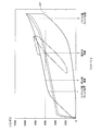
- FIG. 3 shows the relationship between the relative movement amount S (stroke of the cylinder device 10) between the housing 12 and the piston 14 and the internal pressure P of the chamber 16.
- the change amount of the internal pressure P with respect to the change amount of the stroke S that is, the change gradient of the internal pressure P with respect to the stroke S is referred to as a spring constant.
- each characteristic from point A to FB shown in FIG. 3 will be described in order, and a process of deriving an equation that is a concept of the cylinder device design method of the present embodiment will be described.
- K 1 P intr ⁇ Ap / (dV f / Ap) (3)
- Ap is the pressure receiving area of the piston 14.
- the initial compression spring constant K 1 is obtained by dividing the product of the volume modulus of elasticity G 1 of the hydraulic fluid 22 and the square of the piston pressure receiving area Ap by the hydraulic fluid amount V f . Is equal to the value obtained.
- K 1 G 1 ⁇ (Ap 2 / V f ) (5)
- Point C is a point at which the working fluid 22 begins to flow into the pores 30 of the porous body 20.
- the internal pressure of the chamber 16 when the working fluid 22 starts to flow into the pores 30 will be referred to as a cracking pressure P intr .
- the cracking pressure P int is obtained from a balance equation between the internal pressure of the chamber 16 and the internal pressure of the pores 30 (capillary pressure, Laplace pressure). Is done.
- P intr -2 ⁇ ⁇ ⁇ cos ⁇ in / r + P G ⁇ (6)
- sigma is the surface tension of the working fluid 22
- theta in is the contact angle at the inflow of the working fluid 22
- r is the radius of the pores
- P G is compressed air in the pores 30 It is the pressure by what was done.
- the sizes of P G is very small compared to the size of the components that rely on surface tension of the working fluid 22, it can be ignored. That is, it can be seen that a parameter that is dominant when determining the cracking pressure P intr is the radius r (pore diameter d) of the pore 30.
- the cylinder device 10 When the cylinder device 10 is configured to support an object positioned above itself by the internal pressure P of the chamber 16 generated by the state in which the hydraulic fluid 22 flows into the pore 30, the cracking pressure P intr The approximate weight that can be supported by the cylinder device 10 is determined by the pressure receiving area Ap of the piston 14.
- the spring characteristics (hereinafter sometimes referred to as “the spring characteristics of the colloidal solution”) due to the working fluid 22 flowing into the pores 30 of the porous body 20 are referred to as “a colloid solution spring characteristic”. Since this is the main characteristic, the spring constant K 2 (hereinafter sometimes referred to as “the spring constant K 2 of the colloidal solution”), which is the spring characteristic of the colloidal solution, is calculated below.
- the change d ⁇ in the contact area can be expressed by the following equation using dV as the amount of the working fluid 22 flowing in by the stroke of the cylinder device 10.
- d ⁇ 2 ⁇ dV / r (9)
- the inflow amount dV of the hydraulic fluid 22 can be expressed by the following equation using the displacement amount Xp of the piston 14 relative to the housing 12 from the point C.
- dV Ap ⁇ Xp (10)
- Substituting the formulas (9) and (10) into those formulas (8) gives the following formula.
- Point E-Point F-Point B (return path characteristics)
- Point E is a point at which the working fluid 22 starts to flow out of the pores 30 of the porous body 20.
- the pressure in the chamber at this point F is obtained from a balance equation between the internal pressure of the chamber 16 and the internal pressure of the pores 30 and is expressed by the following equation.
- P extr -2 ⁇ ⁇ ⁇ cos ⁇ ex / r + P G ⁇ (19)
- ⁇ ex is the contact angle when the hydraulic fluid 22 flows out.
- the contact angle ⁇ ex at the time of outflow is a value closer to 90 deg than the contact angle ⁇ in at the time of inflow, cos ⁇ ex is small, and the force for the working fluid 22 to flow out of the pore 30 is also small.
- the rubber, resin, seal, the hydraulic fluid 22 in the chamber 16 and the mixed air are released from the compressed state.
- the internal pressure of the chamber 16 rapidly decreases.
- the hydraulic fluid 22 flows out from the pores 30 of the porous body 20 in the section from the point F to the point B, the volume of the colloidal solution 24 increases, and the cylinder device 10 expands. Stroke operation will be performed.
- the cylinder device 10 is configured so that the change in the internal pressure of the chamber 16 in the operation of one cycle from the neutral position, which is a position in a state where the two objects that are moving relative to each other are stopped, If it shows by relationship, it will become like the broken line shown in FIG.
- the cylinder device 10 has a difference between the internal pressure of the chamber 16 when the hydraulic fluid flows in (shrinks) and the internal pressure of the chamber 16 when the hydraulic fluid flows out (expands).
- hysteresis occurs in the change in the internal pressure of the chamber 16 with respect to the change in the stroke S of the cylinder device 10.
- the area surrounded by the two-dot chain line in FIG. 3 corresponds to energy dissipated in one cycle of operation.
- the above broken line is a static characteristic, and the dynamic characteristic becomes elliptical, so that the attenuation efficiency is lowered.
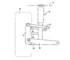
- a cylinder device 50 that is a target of the present design method is a component of a vehicle suspension device and a suspension cylinder that suspends a vehicle body.
- the vehicle suspension device is an independent suspension type device provided corresponding to each of the wheels 52 of the vehicle, and is a multi-link suspension device.
- the suspension device includes a first upper arm 60, a second upper arm 62, a first lower arm 64, a second lower arm 66, and a toe control arm 68, each of which is a suspension arm.
- each of the five arms 60, 62, 64, 66, 68 is rotatably connected to the vehicle body, and the other end is an axle carrier 70 as a wheel holding member that rotatably holds the wheel 52. It is connected to the pivotable. With these five arms 60, 62, 64, 66, 68, the axle carrier 70 is allowed to move up and down along a certain locus with respect to the vehicle body.
- the cylinder device 50 is disposed between a mount portion 72 provided in a tire housing that is a part of the vehicle body and the second lower arm 66.
- the cylinder device 50 uses a colloidal solution in which hydrophobic porous silica gel and water as a working fluid are mixed. That is, in the cylinder device 50, each of the particles of the hydrophobic porous silica gel functions as a porous body.
- the cracking pressure P int is expressed by equation (6) based on the balance equation between the internal pressure of the chamber 16 and the internal pressure of the pore 30 (capillary pressure, Laplace pressure).
- the P intr -2 ⁇ ⁇ ⁇ cos ⁇ in / r + P G ⁇ (6)
- the size of P G is very small compared to the size of the components that rely on surface tension of the working fluid 22, it can be ignored. Since ⁇ and ⁇ in are eigenvalues of water as the working fluid, there is a defined relationship between the cracking pressure P intr and the pore radius r of the porous body.
- N 9 average value
- 'it is substantially the same size as, the reference cracking pressure P intr' the reference cracking pressure P intr reference pressure receiving area Ap 'used for calculating the, and the design value of the pressure receiving area Ap of the piston.
- the internal pressure P of the chamber is the water to the pores of the hydrophobized porous silica gel in the entire range in which the cylinder device 50 is stroked to the contraction side, that is, from full rebound to full bound. It is designed to stroke within the range proportional to the amount of inflow.
- the amount (volume) of hydrophobic porous silica gel and the amount (volume) of water are set. First, in the cylinder device 50, the bounce direction from the neutral position in the standard state (for example, no one is on the vehicle, nothing is loaded, and the vehicle is stopped on the horizontal plane).
- an amount of water equal to the volume change ⁇ V can flow into the hydrophobic porous silica gel.
- ⁇ is the ratio of the limit amount of water in which the hydrophobic porous silica gel can be introduced to the volume of the hydrophobic porous silica gel
- V Smin the required minimum amount (volume) V Smin of the hydrophobic porous silica gel
- the amount (volume) V S ′ of the hydrophobized porous silica gel as a guide was determined by the following equation.
- V S ' V Smin / ⁇
- the initial compression time the spring constant K 1 is a spring constant of from the point B shown in FIG. 3 to point C.
- the initial compression spring constant K 1 has a great influence on the dynamic characteristics of the cylinder device 50, and therefore needs to be set.
- the initial compression spring constant K 1 is expressed by the equation (5).
- K 1 G 1 ⁇ (Ap 2 / V f ) (5)
- the design bulk modulus G 1 was set to 60% of the bulk modulus Gw of water.
- a material is configured to be contained within the chamber. Specifically, as will be described in detail later, the elastic modulus of water is lowered by enclosing compressed air in a sealed container and accommodating the sealed container in the chamber. In addition, the initial pressure of the compressed air in the sealed container is adjusted so that the volume elastic modulus of the chamber becomes the design volume elastic modulus G 1 .
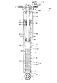
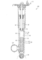
- FIG. 7 shows a cylinder device 50 configured based on the design values determined by the above-described cylinder device design method.
- FIG. 7 is a front sectional view of the cylinder device 50, and the configuration of the cylinder device 50 will be described in detail with reference to FIG.
- the cylinder device 50 includes a generally cylindrical housing 80 and a piston 82 slidably disposed with respect to the housing 80.
- the piston 82 has a piston main body 90, and the piston main body 90 divides the inside of the housing 80 into an upper chamber 92 and a lower chamber 94, which are two chambers, sandwiching itself.
- the piston 82 further includes a piston rod 98, which is connected to the piston main body 90 at the lower end portion and extends from a lid portion provided at the upper end portion of the housing 80. And the piston rod 98 is connected with the lower surface side of the mount part 72 via the upper support 102 comprised including the anti-vibration rubber 100 in the upper end part.
- the housing 80 is connected to the second lower arm 66 through the bush 104 at the lower end thereof.
- the housing 80, the piston rod 98, and the piston main body 90 coupled thereto can be relatively moved in the axial direction in accordance with the approach / separation of the vehicle body (mount portion 72) and the wheel 52 (axle carrier 70). ing.
- the cylinder device 50 can be expanded and contracted according to the approach and separation between the vehicle body and the wheels 52.
- the cylinder device 50 includes a cover tube 110.
- the cover tube 110 accommodates the piston rod 98 and the upper portion of the housing 80, and prevents entry of dust, mud and the like from the outside. Yes.
- a bellows 120 is fixed to the lower end of the housing 80 and is accommodated in the lower chamber 94.
- the bellows 120 is hermetically sealed with a colloidal solution 126 in which a hydrophobic porous silica gel 122 and water 124 are mixed.
- the bellows 120 is configured to expand and contract in the vertical direction while being fixed in the housing 80. Therefore, the bellows 120 is formed in a container shape, and functions as a first sealing member that forms a sealed space only by itself and seals the colloidal solution 126 therein, and this cylinder device 50 includes a colloidal solution sealing body 130 including the bellows 120 and the colloidal solution 124.
- bellows 140 is fixed to the colloidal solution sealing body 130 described above.
- the bellows 140 is sealed with compressed air 142 as a bulk elastic body adjusting substance determined by the previous design method. That is, the bellows 140 functions as a second sealing member.
- the lower chamber 94 is filled with water 150 in a state where the colloidal solution sealing body 130 and the bulk modulus adjusting substance are accommodated.
- the upper chamber 92 is also filled with water 150.
- the piston main body 90 described above is provided with a plurality of communication passages 152 that penetrate the piston main body 90 in the axial direction and connect the upper chamber 92 and the lower chamber 94. That is, when the volumes of the upper chamber 92 and the lower chamber 94 change as the piston 82 slides with respect to the housing 80, the water 150 flows between the upper chamber 92 and the lower chamber 94 by the communication path 152. Is acceptable.
- a plurality of high-pressure seals 154 are provided in the lid portion at the upper end portion and the lid portion at the lower end portion of the housing 80 in order to prevent water 150 from leaking.
- two seals 156 that are in contact with the sliding surface of the piston rod 98 are provided on the lid at the upper end where the piston rod 98 slides. Grease is sealed between the two seals 156 to improve the sealing performance.
- the cylinder device 50 has a mechanism for restricting the approaching and separating operation between the vehicle body and the wheel 52, a so-called bound stopper and a rebound stopper.
- the bound stopper is configured to include an annular buffer rubber 160 attached to the upper inner end of the cover tube 110, and the upper end of the housing 80 contacts the cover tube 110 via the buffer rubber 160. It is configured to touch.
- the rebound stopper is configured to include an annular buffer rubber 162 attached to the lower surface of the upper lid portion of the housing 80, and the upper surface of the piston main body 90 and the upper lid portion of the housing 80 are buffered. It is configured to abut via a rubber 162.
- the colloidal solution 126 is sealed in the bellows 120, but the force applied from the outside is transmitted to the sealed colloidal solution 130 through the water 150. That is, the hydraulic pressure of the water 150 is increased by the force applied from the outside, and the hydraulic pressure of the water 124 accommodated in the bellows 120 is also increased. Then, when the hydraulic pressure of the water 124 rises to a certain height, the water 124 flows into the pores of the hydrophobic porous silica gel 122 against the surface tension. Accordingly, the volume of the colloidal solution sealing body 130 decreases while the bellows 120 contracts.
- FIG. 8 shows a stroke amount and a cylinder when a cylinder device that does not include a bulk modulus adjusting substance, that is, a cylinder device whose initial compression spring constant depends on the volume modulus of water Gw is vibrated. Shows the relationship with force.
- the excitation condition is that the excitation amplitude A is ⁇ 15 mm, ⁇ 25 mm, ⁇ 35 mm, and the frequency is constant at 0.53 Hz. As can be seen from FIG.
- the dynamic spring constant is almost the same as the spring constant based on the volumetric modulus Gw of water, which is the spring constant at the time of initial compression. . That is, in the cylinder device functioning as a colloidal damper, the dynamic spring constant is greatly affected by the initial compression spring constant when vibration having a small amplitude occurs.
- the cylinder device 50 the initial compression time the spring constant K 1 is the bulk modulus adjustment material, the bulk modulus of water are smaller than reliance on the spring constant, a small vibration amplitude occurs In this case, deterioration of the attenuation performance is suppressed.
- the relationship between the stroke amount of the cylinder device 50 and the cylinder force is shown by the solid line in FIG.
- the amount that can be bound stroke is larger than the amount that can be rebound stroke from the state where the vehicle is stopped.
- the position where the cylinder force having the same magnitude as the shared load Wcf is generated is located on the rebound side from the center of the stroke possible range. That is, the vehicle height in the stop state is set to be high.
- the initial pressure is applied in the housing 80 by closing the upper cover of the housing 80 in a state where the pressure set in the piston 82 is applied. Accordingly, the cylinder force is balanced with the shared load Wcf on the rebound side from the center of the stroke possible range.
- the change in the cylinder force when starting a stroke from the stopped state to the bounce side and then performing two cycles thereafter is shown by a two-dot chain line. While the stroke to the bounce side in the first cycle operates along the static characteristics indicated by the solid line, the increase in cylinder force is delayed in the stroke to the bounce side in the second cycle. I understand. Thus, when the vehicle body and the wheel 52 are relatively moved, the vehicle height is lower than the stopped state. As described above, the cylinder device 50 is set so that the vehicle height in the stopped state is high, so that the amount of stroke possible in both the bound side and the rebound side is appropriate because the vehicle height decreases during traveling. Will be converted.
- the cylinder device design method according to the second embodiment is different from the design method according to the first embodiment in a method for realizing the initial compression spring constant K 1 set by the initial compression spring constant setting process. Therefore, only the design method of the second embodiment will be described, and then the cylinder device 200 designed by the design method of the second embodiment will be described.
- the initial compression spring constant K 1 is expressed by equation (5).
- K 1 G 1 ⁇ (Ap 2 / V f ) (5)
- the initial compression spring set to a magnitude of about 60% of the spring constant depending on the volume elastic modulus Gw of the water, the previously determined design pressure receiving area Ap of the piston, and the volume elastic modulus Gw of the water.
- the amount of hydraulic fluid V f that is, the total amount of water in the chamber was determined based on the above equation (5).
- FIG. 10 is a front sectional view of the cylinder device 200 configured based on the design value determined by the cylinder device design method of the second embodiment. Since the cylinder device 200 includes the same components as the cylinder device 50 of the first embodiment, description thereof will be omitted.
- the cylinder device 200 has substantially the same configuration as the cylinder device 50 of the first embodiment, but the compressed air 120, which is a volume elastic modulus adjusting material included in the cylinder device of the first embodiment, is accommodated in the chamber. It has not been.
- the cylinder device 200 of this embodiment includes a sub housing 210.
- the sub-housing 210 is connected to the lower end of the housing 80, and the inside of the sub-housing 210 communicates with the lower chamber 94 of the housing 80.
- the sub housing 210 is also filled with water 150 that is a working fluid.
- the volume of the sub housing 210 is determined based on the amount of hydraulic fluid V f determined by the design method described above. In other words, the volume of the sub-housing 210 can accommodate an amount obtained by subtracting the amount of water stored in the housing 80 and the amount of water in the colloid solution sealed body 130 from the amount of hydraulic fluid V f. It has been decided.
- the cylinder device 200 of the present embodiment also has an initial compression spring constant K 1 smaller than a spring constant that depends on the volume modulus of water Gw, and vibration with a small amplitude. In this case, the deterioration of the attenuation performance in the case of the occurrence of the phenomenon is suppressed.
- Cylinder device 12 Housing 14: Piston 16: Chamber 20: Porous body 22: Hydraulic fluid 30: Pore 50: Cylinder device [suspension cylinder] 52: Wheel 70: Axle carrier [Wheel holding member] 72: Mount part [Body] 80: Housing 82: Piston 92: Upper chamber 94: Lower chamber [chamber] 120: Bellows (first sealing member) 122: Hydrophobized porous silica gel [porous body] 124: Water [hydraulic fluid] 140: Bellows [second sealing member] 142: Compressed air [volume elastic modulus adjusting substance] 150: Water [hydraulic fluid] 200: Cylinder device 210: Sub housing
Landscapes
- Engineering & Computer Science (AREA)
- General Engineering & Computer Science (AREA)
- Mechanical Engineering (AREA)
- Fluid-Damping Devices (AREA)
- Combined Devices Of Dampers And Springs (AREA)
Abstract
Description
前記ハウジングが、前記車体と前記車輪保持部材との一方に連結されるものであるとともに、前記ピストンが、前記車体と前記車輪保持部材との他方に連結されるものであり、
当該シリンダ装置が、車両用サスペンション装置を構成して、前記車体を懸架する懸架シリンダとされ、
当該シリンダ装置設計方法が、その懸架シリンダとされたシリンダ装置の設計方法である(1)項に記載のシリンダ装置設計方法。
前記2つの物のうちの上方側に位置する物の重量に応じて、前記多孔質体の細孔に作動液が流入し始める時の前記チャンバの内圧であるクラッキング圧の目安となる基準クラッキング圧を設定するクラッキング圧設定プロセスと、
前記チャンバの内圧と前記多孔質体の細孔の内圧との釣り合いに基づいて定まる前記クラッキング圧と前記多孔質体の細孔径との関係を根拠に、前記基準クラッキング圧に基づいて、前記多孔質体の細孔径の目安となる基準細孔径を決定する細孔径決定プロセスと
を含む(1)項ないし(4)項のいずれか1つに記載のシリンダ装置設計方法。
前記ピストンの受圧面積の目安となる基準受圧面積を設定し、その基準受圧面積と、前記2つの物のうちの上方側に位置する物の重量とに基づいて、前記基準クラッキング圧を設定する(5)項に記載のシリンダ装置設計方法。
前記基準クラッキング圧,前記基準細孔径,および前記ピストンの受圧面積の目安となる基準受圧面積に基づいて、当該シリンダ装置に用いる前記多孔質体を決定するとともに、その多孔質体に応じた前記クラッキング圧の設計値および前記ピストンの受圧面積の設計値を決定する設計値決定プロセスを含む(5)項または(6)項に記載のシリンダ装置。
前記多孔質体の細孔に作動液が流入し始めるまでの当該シリンダ装置のストローク量に対する前記チャンバの内圧の変化勾配である初期圧縮時ばね定数を設定する初期圧縮時ばね定数設定プロセスを含む(1)項ないし(7)項のいずれか1つに記載のシリンダ装置設計方法。
前記初期圧縮時ばね定数を、水の体積弾性率に依拠して定まるばね定数より小さい値に設定する(8)項に記載のシリンダ装置設計方法。
前記作動液を選定するとともに前記ピストンの受圧面積を設定し、その選定された作動液の体積弾性率,設定された前記ピストンの受圧面積,および前記設定された初期圧縮時ばね定数に基づき、前記初期圧縮時ばね定数が前記作動液の体積弾性率と前記ピストンの受圧面積の2乗との積を前記作動液の量で除した値に等しいことを根拠に、前記作動液の量を決定する作動液量決定プロセスを含む(8)項または(9)項に記載のシリンダ装置設計方法。
前記ピストンの受圧面積,前記作動液の量を設定し、その設定された前記ピストンの受圧面積,前記作動液の量,および前記設定された初期圧縮時ばね定数に基づき、前記初期圧縮時ばね定数が前記作動液の体積弾性率と前記ピストンの受圧面積の2乗との積を前記作動液の量で除した値に等しいことを根拠に算出される体積弾性率を、設計体積弾性率として決定する体積弾性率決定プロセスと、
体積弾性率が前記作動液の体積弾性率と異なる物質をチャンバ内に収容して、前記チャンバに加わる力に対する前記チャンバの容積変化の逆数である前記チャンバの体積弾性率を前記設計体積弾性率に調整すべく、そのチャンバ内に収容する物質を決定する体積弾性率調整物質決定プロセスと
を含む(8)項または(9)項に記載のシリンダ装置設計方法。
前記2つの物の他方に連結されて前記ハウジング内を摺動可能なピストンと、
前記ハウジングと前記ピストンとによって区画形成されたチャンバの内部に収容された多数の細孔を有する多孔質体および作動液と、
可撓性を有し、前記チャンバの内部に密封空間を区画形成するとともにその密封空間に前記多孔質体と前記作動液の一部とをそれらが混合した状態で密封し、自身が変形することによって、前記密封空間の容積の変化を許容する密封部材と
を備え、
前記多孔質体の細孔に前記作動液が流入した状態によって生じる前記密封空間内の圧力に依存して、前記2つの物のうちの上方側に位置する物を支持するとともに、前記2つの物の相対動作に応じて、前記多孔質体の細孔へ流入している前記作動液の量が変化することによって、それら2つの物の相対動作を減衰させることで、コロイダルダンパとして機能するシリンダ装置。
前記チャンバの内部における前記密封空間の外部に収容され、体積弾性率が前記作動液の体積弾性率と異なる物質を備えた(21)項に記載のシリンダ装置。
前記物質が、体積弾性率が水の体積弾性率より低いものである(22)項に記載のシリンダ装置。
当該シリンダ装置が、可撓性を有して前記物質を内部に密封する第2密封部材を備えた(22)項ないし(24)項のいずれか1つに記載のシリンダ装置。
前記ハウジングに連結され、自身の内部が前記ハウジングの内部と連通して前記チャンバを区画形成するサブハウジングを備えた(21)項に記載のシリンダ装置。
前記2つの物が停止している状態から、収縮側にストローク可能な量が、伸張側にストローク可能な量に比較して大きくなるように構成された(21)項ないし(27)項のいずれか1つに記載のシリンダ装置。
本実施例のシリンダ装置設計方法の説明の前に、まず、図1に示す簡便な構成のコロイダルダンパとして機能するシリンダ装置10を例に、コロイダルダンパの特性について詳しく説明する。シリンダ装置10は、ハウジング12と、そのハウジング12内を摺動するピストン14とを含んで構成される。そして、シリンダ装置10は、それらハウジング12とピストン14とによって形成されるチャンバ16内に、多孔質体20と作動液22とが混合されたコロイド溶液24が充填されたものである。図2に、多孔質体20の断面図を模式的に示す。多孔質体20は、外径Dが数μm~数十μmオーダの球形状の粒子であり、内径dが数nm~数十nmオーダの多数の細孔30を有するものである。
点Aから点Bまでは、シリンダ装置10の組付時等にチャンバ16内に混入してしまう空気、複数の多孔質体20の間の空気、および、シール部間隙の空気等の存在によって生じるストローク、つまり、無駄ストロークである。
点Bから点Cまでは、シリンダ装置10の収縮ストロークに伴って、シリンダ装置10が有するゴム,樹脂,シールや、チャンバ16内の作動液22,混入してしまった空気等が圧縮することにより、チャンバ16の内圧Pが上昇する過程である。なお、その主な要素は、作動液22の圧縮によるものであるため、このB-C間のばね定数を、作動液22の圧縮率βfに基づいて算出する。その作動液22の圧縮率βfは、下記の(1)式で表せすことができる。
βf=(dVf/Pintr)・(1/Vf) ・・・(1)
ここで、Vfが作動液量であり、dVfがその作動液22の体積変化であり、Pintrが、後に詳しく説明するが、作動液22が多孔質体20内に流入する際のチャンバ16の内圧である。また、上記(1)式を変形し、作動液22の体積変化dVfを表した式が、下記の(2)式である。
dVf=βf・Pintr・Vf ・・・(2)
次に、B-C間のばね定数である初期圧縮時ばね定数K1は、下記の(3)式で表すことができる。
K1=Pintr・Ap/(dVf/Ap)・・・(3)
ここで、Apは、ピストン14の受圧面積である。この(3)式に、上記(2)式を代入すると、以下の式が得られる。
K1=Pintr・Ap2/(βf・Pintr・Vf)=1/βf・(Ap2/Vf) ・・・(4)
上記(4)式の1/βは、作動液22の圧縮率βの逆数であり、作動液22の体積弾性率G1である。つまり、下記(5)式に示すように、初期圧縮時ばね定数K1は、作動液22の体積弾性率G1とピストンの受圧面積Apの2乗との積を作動液量Vfで除した値に等しくなるのである。
K1=G1・(Ap2/Vf) ・・・(5)
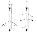
点Cは、多孔質体20が有する細孔30内に、作動液22が流入し始めるポイントである。以下、この細孔30内に作動液22が流入し始める時のチャンバ16の内圧をクラッキング圧Pintrと呼ぶこととする。このクラッキング圧Pintは、図4(a)の概念図に示すように、チャンバ16の内圧と細孔30の内圧(毛管の圧力,ラプラス圧力)との釣り合い式から求められ、次式で表される。
Pintr=-2・σ・cosθin/r+PG ・・・(6)
ここで、σは作動液22の表面張力であり、θinは作動液22の流入時の接触角であり、rは細孔30の半径であり、PGは細孔30内の空気が圧縮されたことによる圧力である。ちなみに、そのPGの大きさは、作動液22の表面張力に依拠した成分の大きさに比較して非常に小さいため、無視することが可能である。つまり、クラッキング圧Pintrを定める際に支配的なパラメータは、細孔30の半径r(細孔径d)であることが分かる。そして、シリンダ装置10を、細孔30内に作動液22が流入した状態によって生じるチャンバ16の内圧Pによって、自身の上方に位置する物を支持するように構成する場合、このクラッキング圧Pintrとピストン14の受圧面積Apとによって、シリンダ装置10が支持することが可能なおおよその重量が定まることになるのである。
チャンバ16の内圧がクラッキング圧に到達し、さらに、シリンダ装置10をストロークさせると、作動液22がさらに圧縮するとともに、それによる液圧の上昇によって多孔質体20の細孔30への作動液22の流入量が増加することになる。そして、その多孔質体20への作動液22の流入によって、コロイド溶液24の体積が減少し、シリンダ装置10が収縮するようにストロークすることになる。つまり、点CからD付近までの区間においては、シリンダ装置10は、上述した作動液22の体積弾性率G1に依存した特性のばねと、多孔質体20の細孔30に作動液22が流入することによる特性のばねとが直列に配置されたばね特性を有すると考えることができる。つまり、多孔質体20の細孔30に作動液22が流入することに依拠したばね特性のばね定数をK2とすれば、この点CからD付近までの区間のばね定数Kallは、次式によって表すことができる。
Kall=1/(1/K1+1/K2) ・・・(7)
この点CからD付近までの区間においては、多孔質体20の細孔30に作動液22が流入することによるばね特性(以下、「コロイド溶液のばね特性」と呼ぶ場合がある。)が、主な特性であるため、以下に、そのコロイド溶液のばね特性であるばね定数K2(以下、「コロイド溶液のばね定数K2」と呼ぶ場合がある。)を算出する。
E=-σ・dΩ・cosθin ・・・(8)
dΩ=2・dV/r ・・・(9)
また、その作動液22の流入量dVは、点Cからのハウジング12に対するピストン14の変位量Xpを用いて、次式で表すことができる。
dV=Ap・Xp ・・・(10)
それら(8)式に(9)式および(10)式を代入すると、次式が得られる。
E=-2・σ・cosθin・Ap・Xp/r ・・・(11)
一方、シリンダ装置10がばね定数K2のスプリングとして機能すると考えた場合に、そのシリンダ装置10が持つ位置エネルギは、次式であらわすことができる。
E=1/2・K2・Xp2 ・・・(12)
これら(11)式および(12)式から、次式が得られる。
-2・σ・cosθin・Ap・Xp/r=1/2・K2・Xp2 ・・・(13)
この(13)式を、コロイド溶液のばね定数K2について変形すれば、次式となる。
K2=-4・σ・Ap・cosθin/(r・Xp) ・・・(14)
なお、点Cからの線形領域とする変位量(有効ストローク)をXprとすれば、その有効ストロークXprは、多孔質体20の量Vpm,その多孔質体20の細孔容積率δvp,多孔質体の密度ρ,ピストン14の受圧面積Apを用いて、次式で表すことができる。
Xpr=Vpm・δvp・ρ/Ap ・・・(15)
この(15)式を(14)式に代入して、有効ストローク範囲のコロイド溶液のばね定数を算出したものが、次式である。
K2=-4・σ・Ap2・cosθin/(r・Vpm・δvp・ρ) ・・・(16)
この(16)式のうちの多孔質体20および作動液22が持つ固有値のみで定まる要素をG2とすれば、(16)式は、以下のようにまとめることができる。
K2=G2・(Ap2/Vpm) ・・・(17)
G2=-4・σ・cosθin/(r・δvp・ρ) ・・・(18)
つまり、このG2は、コロイド溶液の体積弾性率G2に相当するものと考えることができる。
点D付近~点E(非線形領域)においては、作動液22が、流入できる限界付近まで多孔質体20内に流入すると、作動液22の液圧が大きく上昇し始める。ちなみに、この領域において非線形となる要因は明らかにはなっていないが、例えば、多孔質体20の重量に対する細孔容積率、細孔径の勾配、多孔質体20が疎水化されたものである場合の疎水化処理の濃淡等が起因するのではないかと考えられている。
点Eにおいて、シリンダ装置10のストロークが収縮側から伸張側に反転するポイントである。また、点Fは、多孔質体20が有する細孔30内から、作動液22が流出し始めるポイントである。この点Fでのチャンバ内の圧力は、図4(b)の概念図に示すように、チャンバ16の内圧と細孔30の内圧との釣り合い式から求められ、次式で表される。
Pextr=-2・σ・cosθex/r+PG ・・・(19)
ここで、θexは作動液22の流出時の接触角である。その流出時の接触角θexは、流入時の接触角θinより90degに近い値となるためcosθexが小さく、作動液22が細孔30内から流出しようとする力も小さくなる。そのことにより、点Eから点Fまでの区間においては、シリンダ装置10が有するゴム,樹脂,シールや、チャンバ16内の作動液22,混入してしまった空気等が圧縮した状態から解放されて、急激にチャンバ16の内圧が低下することになる。そして、チャンバ16の内圧が低下すると、点Fから点Bまでの区間において、多孔質体20の細孔30から作動液22が流出し、コロイド溶液24の体積が増加し、シリンダ装置10が伸張するようにストローク動作することになる。
シリンダ装置10は、相対動作する2つの物が停止している状態における位置である中立位置からの1サイクルの動作におけるチャンバ16の内圧の変化を、シリンダ装置10のストロークSとの関係で示せば、図3に示す破線のようになる。シリンダ装置10は、先にも説明したように、作動液流入時(収縮時)のチャンバ16の内圧と、作動液流出時(伸張時)のチャンバ16の内圧とに差が生じ、図3に示すように、シリンダ装置10のストロークSの変化に対するチャンバ16の内圧の変化に、ヒステリシスが生じる。そして、その図3の二点鎖線によって囲まれた面積が、1サイクルの動作において散逸したエネルギに相当する。なお、上記の破線は、静的な特性であり、動的な特性は、楕円化するため、減衰効率は落ちることになる。
i)クラッキング圧設定プロセス
まず、疎水化多孔質シリカゲル粒子の細孔内に水が流入した状態におけるチャンバの内圧によって、車体の分担荷重Wcf(=6000N)を受け持つように、シリンダ装置50を設計する。シリンダ装置50が発生させる力は、チャンバの内圧Pとピストンの受圧面積Apとの積によって定まるため、まず、一般的な車両用のシリンダ装置の受圧面積を考慮して、ピストンの受圧面積の目安となる基準受圧面積Ap'(=2.01cm2)を設定した。その基準受圧面積Ap'に基づけば、中立位置におけるチャンバの内圧PとしてWcf/Ap'(=29.9MPa)だけ必要である。また、車体と車輪との相対動作範囲,図3の点CからD付近までの区間のばね定数Kallを一般的な車両のばね定数を目標値とすることを考慮し、クラッキング圧の目安となる基準クラッキング圧Pintr'(=25MPa)を設定した。
クラッキング圧Pintは、上述したように、チャンバ16の内圧と細孔30の内圧(毛管の圧力,ラプラス圧力)との釣り合い式に基づいて、(6)式で表される。
Pintr=-2・σ・cosθin/r+PG ・・・(6)
ちなみに、PGの大きさは、作動液22の表面張力に依拠した成分の大きさに比較して非常に小さいため、無視することが可能である。そして、σおよびθinは、作動液である水が持つ固有値であるため、クラッキング圧Pintrと多孔質体の細孔の半径rとの間には定められた関係がある。つまり、その(6)式を根拠に、水の表面張力σ(=72.8mN/m),水の表面張力の流入時の接触角θin(=128.5deg),上記の基準クラッキング圧Pintr'に基づき、多孔質体である疎水化多孔質シリカゲルの細孔径の目安となる基準細孔半径r'(=-2・σ・cosθin/Pintr'=3.62nm)を決定した。
次に、疎水化多孔質シリカゲルの細孔径が異なるものを3種類用意した。細孔半径が、3.5nm,5.0nm,7.5nmのものである。それらのストローク量とシリンダ力との関係を実測したものを、図6に示す。なお、実測に用いたシリンダ装置のピストンは、上記基準受圧面積Ap'とされたものである。図6からも、基準細孔半径r'に近い細孔半径3.5nmのものが、分担荷重Wcf(=6000N)を受け持つのに、最適であることが分かる。したがって、多孔質シリカゲルの細孔径の設計値を、7nm(半径3.5nm)と決定した。なお、上記の細孔半径3.5nmの疎水化多孔質シリカゲルを用いたシリンダ装置のクラッキング圧の実測値は、25.55MPa(N=9の平均値)であった。つまり、上記基準クラッキング圧Pintr'とほぼ同じ大きさであるため、その基準クラッキング圧Pintr'を算出するのに用いた基準受圧面積Ap'を、ピストンの受圧面積Apの設計値とした。
また、本設計方法においては、シリンダ装置50を、収縮側にストロークする全範囲において、つまり、フルリバウンドからフルバウンドまでの間において、チャンバの内圧Pが疎水化多孔質シリカゲルの細孔への水の流入量に比例する範囲内でストロークするように設計する。シリンダ装置50を、そのような構成とするために、疎水化多孔質シリカゲルの量(体積)と水の量(体積)を設定する。まず、シリンダ装置50において、標準状態(例えば、車両に一人も乗車しておらず、かつ、何も積載しておらず、さらに、水平面上において停車している状態)における中立位置から、バウンド方向にストローク量Sb(=70mm),リバウンド方向にストローク量Sr(=70mm)だけストロークできるようにすると、フルリバウンドからフルバウンドまでのチャンバの容積変化ΔVは、次式のように求まる。
ΔV=Ap・(Sb+Sr)
VSmin=ΔV/η
なお、疎水化多孔質シリカゲルは、疎水化処理の際に、全てが疎水化されずに吸水性を有するシリカゲルが残ってしまう場合がある。例えば、疎水化処理を行った全量に対する、疎水化されなかったシリカゲルの量を除いた疎水化されたシリカゲルの量の割合を、疎水化率αと定義すれば、その疎水化率のばらつき等に対応するために、目安となる疎水化多孔質シリカゲルの量(体積である)VS'を、次式によって決定した。
VS'=VSmin/α
i)初期圧縮時ばね定数設定プロセス
次に、本設計方法においては、図3に示す点Bから点Cまでのばね定数である初期圧縮時ばね定数K1を設定する。後に詳しく説明するが、この初期圧縮時ばね定数K1は、シリンダ装置50の動特性に大きく影響するため、これを設定する必要があるのである。本設計方法においては、初期圧縮時ばね定数K1を、水の体積弾性率Gw(=1/βw,βw:水の圧縮率)に依拠したばね定数より小さな値となるように、具体的には、水の体積弾性率Gw(=1/βw,βw:水の圧縮率)に依拠したばね定数の60%程度の値となるように設定した
先に述べたように、初期圧縮時ばね定数K1は、(5)式で表される。
K1=G1・(Ap2/Vf) ・・・(5)
その作動液量は、シリンダ装置のハウジングの容積の設定値VHから、先に設定された疎水化多孔質シリカゲルの量VS'を引いた容積である。そして、その目安となる作動液量Vf'(=VH-VS')と、先に決定されたピストンの設計受圧面積Ap(==2.01cm2)とに基づけば、上記(5)式を根拠に、チャンバの体積弾性率の設計値である設計体積弾性率G1を決定する。つまり、本設計方法においては、初期圧縮時ばね定数K1を、水の体積弾性率Gw(=1/βw,βw:水の圧縮率)に依拠したばね定数の60%程度の大きさとなるように、設計体積弾性率G1を、水の体積弾性率Gwの60%の大きさに設定した。
本設計方法においては、シリンダ装置50を、上記設計体積弾性率G1(=0.6・Gw)を実現するために、作動液としての水の弾性率を低下させる物質をチャンバ内に収容するように構成する。具体的には、後に詳しく説明するが、密封容器内に圧縮した空気を封入させ、その圧縮空気が密封された容器をチャンバ内に収容させることで、水の弾性率を低下させる。なお、チャンバの体積弾性率が、上記設計体積弾性率G1となるように、密封容器内の圧縮空気の初期圧を調整する。
i)コロイド溶液ばね定数決定プロセス
次に、上記の(7)式を利用して、コロイダル溶液のばね定数K2を決定する。
Kall=1/(1/K1+1/K2) ・・・(7)
図3に示した点Cから点D付近のばね定数Kallは、一般的な車両に用いられるサスペンションスプリングのばね定数Ktc(=36010N/m)に設定した。そして、コロイダル溶液のばね定数K2を、そのばね定数Ktcと、先に決定された初期圧縮時ばね定数K1とに基づき、(7)式を利用して決定した。
先に述べたように、コロイダル溶液のばね定数K2は、上記の(17)式で表される。
K2=G2・(Ap2/Vpm) ・・・(17)
このG2は、上記の(18)式で表されるものであり、多孔質体としての疎水化多孔質シリカゲルおよび作動液としての水が持つ固有値のみで定まるものである。
G2=-4・σ・cosθin/(r・δvp・ρ) ・・・(18)
つまり、このコロイド溶液の体積弾性率と、先に決定されたピストンの設計受圧面積Ap(=2.01cm2)、および、上記のように決定されたコロイダル溶液のばね定数K2に基づき、(17)式を根拠に、疎水化多孔質シリカゲルの量VSを決定した。
上記のシリンダ装置設計方法により決定された設計値をもとに構成されたシリンダ装置50を、図7に示す。図7は、シリンダ装置50の正面断面図であり、その図7を参照しつつ、シリンダ装置50の構成を詳しく説明する。
本シリンダ装置50は、上述した設計方法によって、初期圧縮時ばね定数K1が適切化されている。図8に、体積弾性率調整物質を備えていないシリンダ装置、つまり、初期圧縮時ばね定数が水の体積弾性率Gwに依拠した大きさとされているシリンダ装置を加振した場合のストローク量とシリンダ力との関係を示す。加振条件は、加振振幅Aが、±15mm,±25mm,±35mmで、周波数は0.53Hzで一定である。図8から分かるように、振幅が小さい場合ほど、疎水化多孔質シリカゲルへの水の流入・流出がなく、作動液である水の体積変化に依拠したストロークしか行われていない。特に、加振振幅が±15mmである場合には、動的なばね定数が、初期圧縮時ばね定数である水の体積弾性率Gwに依拠したばね定数と、ほぼ同程度となってしまっている。つまり、コロイダルダンパとして機能するシリンダ装置は、振幅の小さな振動が生じている場合に動的なばね定数が、初期圧縮時ばね定数の影響を大きく受けることになる。それに対して、本シリンダ装置50は、初期圧縮時ばね定数K1が、体積弾性率調整物質によって、水の体積弾性率に依拠したばね定数より小さくされており、振幅の小さな振動が生じている場合の減衰性能の悪化が抑制されたものとなっている。
先に述べたように、初期圧縮時ばね定数K1は、(5)式で表される。
K1=G1・(Ap2/Vf) ・・・(5)
本シリンダ装置200の作動液は、第1実施例のシリンダ装置50と同様に水であるため、チャンバの体積弾性率G1は、水の体積弾性率Gwと等価と考える。そして、その水の体積弾性率Gw、先に決定されたピストンの設計受圧面積Ap、および、水の体積弾性率Gwに依拠したばね定数の60%程度の大きさに設定された初期圧縮時ばね定数K1に基づき、上記(5)式を根拠に、作動液量Vf、つまり、チャンバ内のトータルの水の量を決定した。
上記第2実施例のシリンダ装置設計方法により決定された設計値をもとに構成されたシリンダ装置200を、図10の正面断面図に示す。なお、このシリンダ装置200は、第1実施例のシリンダ装置50と同じ構成要素を含むため、それらの説明は省略するものとする。
Claims (9)
- (A)相対動作する2つの物の一方に連結されるハウジングと、(B)前記2つの物の他方に連結されて前記ハウジング内を摺動可能なピストンと、(C)前記ハウジングと前記ピストンとによって区画形成されたチャンバの内部に収容された多数の細孔を有する多孔質体および作動液とを備え、(i)前記2つの物のうちの上方側に位置する物を、前記多孔質体の細孔に前記作動液が流入した状態によって生じる前記チャンバの内圧に依存して支持するとともに、(ii)前記2つの物の相対動作に応じて前記多孔質体の細孔へ流入している前記作動液の量が変化することによって、それら2つの物の相対動作を減衰させ、コロイダルダンパとして機能するシリンダ装置の設計方法であって、
前記2つの物のうちの上方側に位置する物の重量に応じて、前記多孔質体の細孔に作動液が流入し始める時の前記チャンバの内圧であるクラッキング圧の目安となる基準クラッキング圧を設定するクラッキング圧設定プロセスと、
前記チャンバの内圧と前記多孔質体の細孔の内圧との釣り合いに基づいて定まる前記クラッキング圧と前記多孔質体の細孔径との関係を根拠に、前記基準クラッキング圧に基づいて、前記多孔質体の細孔径の目安となる基準細孔径を決定する細孔径決定プロセスと
を含むシリンダ装置設計方法。 - 前記クラッキング圧設定プロセスにおいて、
前記ピストンの受圧面積の目安となる基準受圧面積を設定し、その基準受圧面積と、前記2つの物のうちの上方側に位置する物の重量とに基づいて、前記基準クラッキング圧を設定する請求項1に記載のシリンダ装置設計方法。 - (A)相対動作する2つの物の一方に連結されるハウジングと、(B)前記2つの物の他方に連結されて前記ハウジング内を摺動可能なピストンと、(C)前記ハウジングと前記ピストンとによって区画形成されたチャンバの内部に収容された多数の細孔を有する多孔質体および作動液とを備え、(i)前記2つの物のうちの上方側に位置する物を、前記多孔質体の細孔に前記作動液が流入した状態によって生じる前記チャンバの内圧に依存して支持するとともに、(ii)前記2つの物の相対動作に応じて前記多孔質体の細孔へ流入している前記作動液の量が変化することによって、それら2つの物の相対動作を減衰させ、コロイダルダンパとして機能するシリンダ装置の設計方法であって、
前記多孔質体の細孔に作動液が流入し始めるまでの当該シリンダ装置のストローク量に対する前記チャンバの内圧の変化勾配である初期圧縮時ばね定数を設定する初期圧縮時ばね定数設定プロセスと、
前記作動液を選定するとともに前記ピストンの受圧面積を設定し、その選定された作動液の体積弾性率,設定された前記ピストンの受圧面積,および前記設定された初期圧縮時ばね定数に基づき、前記初期圧縮時ばね定数が前記作動液の体積弾性率と前記ピストンの受圧面積の2乗との積を前記作動液の量で除した値に等しいことを根拠に、前記作動液の量を決定する作動液量決定プロセスと
を含むシリンダ装置設計方法。 - (A)相対動作する2つの物の一方に連結されるハウジングと、(B)前記2つの物の他方に連結されて前記ハウジング内を摺動可能なピストンと、(C)前記ハウジングと前記ピストンとによって区画形成されたチャンバの内部に収容された多数の細孔を有する多孔質体および作動液とを備え、(i)前記2つの物のうちの上方側に位置する物を、前記多孔質体の細孔に前記作動液が流入した状態によって生じる前記チャンバの内圧に依存して支持するとともに、(ii)前記2つの物の相対動作に応じて前記多孔質体の細孔へ流入している前記作動液の量が変化することによって、それら2つの物の相対動作を減衰させ、コロイダルダンパとして機能するシリンダ装置の設計方法であって、
前記多孔質体の細孔に作動液が流入し始めるまでの当該シリンダ装置のストローク量に対する前記チャンバの内圧の変化勾配である初期圧縮時ばね定数を設定する初期圧縮時ばね定数設定プロセスと、
前記ピストンの受圧面積,前記作動液の量を設定し、その設定された前記ピストンの受圧面積,前記作動液の量,および前記設定された初期圧縮時ばね定数に基づき、前記初期圧縮時ばね定数が前記作動液の体積弾性率と前記ピストンの受圧面積の2乗との積を前記作動液の量で除した値に等しいことを根拠に算出される体積弾性率を、設計体積弾性率として決定する体積弾性率決定プロセスと、
体積弾性率が前記作動液の体積弾性率と異なる物質をチャンバ内に収容して、前記チャンバに加わる力に対する前記チャンバの容積変化の逆数である前記チャンバの体積弾性率を前記設計体積弾性率に調整すべく、そのチャンバ内に収容する物質を決定する体積弾性率調整物質決定プロセスと
を含むシリンダ装置設計方法。 - 前記初期圧縮時ばね定数設定プロセスにおいて、
前記初期圧縮時ばね定数を、水の体積弾性率に依拠して定まるばね定数より小さい値に設定する請求項3また請求項4に記載のシリンダ装置設計方法。 - (A)相対動作する2つの物の一方に連結されるハウジングと、(B)前記2つの物の他方に連結されて前記ハウジング内を摺動可能なピストンと、(C)前記ハウジングと前記ピストンとによって区画形成されたチャンバの内部に収容された多数の細孔を有する多孔質体および作動液と、(D)可撓性を有し、前記チャンバの内部に密封空間を区画形成するとともにその密封空間に前記多孔質体と前記作動液の一部とをそれらが混合した状態で密封し、自身が変形することによって、前記密封空間の容積の変化を許容する密封部材とを備え、(i)前記多孔質体の細孔に前記作動液が流入した状態によって生じる前記密封空間内の圧力に依存して、前記2つの物のうちの上方側に位置する物を支持するとともに、(ii)前記2つの物の相対動作に応じて、前記多孔質体の細孔へ流入している前記作動液の量が変化することによって、それら2つの物の相対動作を減衰させることで、コロイダルダンパとして機能するシリンダ装置であって、
当該シリンダ装置が、さらに、
前記チャンバの内部における前記密封空間の外部に収容され、体積弾性率が前記作動液の体積弾性率と異なる物質を備え、
前記作動液が、水であり、前記物質が、体積弾性率が水の体積弾性率より低いものであるシリンダ装置。 - 前記密封部材を、第1密封部材とした場合に、
当該シリンダ装置が、可撓性を有して前記物質を内部に密封する第2密封部材を備えた請求項6に記載のシリンダ装置。 - (A)相対動作する2つの物の一方に連結されるハウジングと、(B)前記2つの物の他方に連結されて前記ハウジング内を摺動可能なピストンと、(C)前記ハウジングと前記ピストンとによって区画形成されたチャンバの内部に収容された多数の細孔を有する多孔質体および作動液と、(D)可撓性を有し、前記チャンバの内部に密封空間を区画形成するとともにその密封空間に前記多孔質体と前記作動液の一部とをそれらが混合した状態で密封し、自身が変形することによって、前記密封空間の容積の変化を許容する密封部材とを備え、(i)前記多孔質体の細孔に前記作動液が流入した状態によって生じる前記密封空間内の圧力に依存して、前記2つの物のうちの上方側に位置する物を支持するとともに、(ii)前記2つの物の相対動作に応じて、前記多孔質体の細孔へ流入している前記作動液の量が変化することによって、それら2つの物の相対動作を減衰させることで、コロイダルダンパとして機能するシリンダ装置であって、
当該シリンダ装置が、さらに、
前記ハウジングに連結され、自身の内部が前記ハウジングの内部と連通して前記チャンバを区画形成するサブハウジングを備え、
そのサブハウジングの容積が、前記ハウジングの容積から前記多孔質体の体積を除いた部分の容積の45パーセント以上100パーセント以下とされたシリンダ装置。 - 当該シリンダ装置が、
前記2つの物が停止している状態から、収縮側にストローク可能な量が、伸張側にストローク可能な量に比較して大きくなるように構成された請求項6ないし請求項8のいずれか1つに記載のシリンダ装置。
Priority Applications (6)
| Application Number | Priority Date | Filing Date | Title |
|---|---|---|---|
| JP2013514908A JP5637306B2 (ja) | 2011-05-17 | 2011-05-17 | シリンダ装置設計方法 |
| US14/110,820 US20140067340A1 (en) | 2011-05-17 | 2011-05-17 | Method for designing cylinder device and cylinder device |
| DE112011105254.5T DE112011105254T5 (de) | 2011-05-17 | 2011-05-17 | Verfahren zur Konstruktion einer Zylindervorrichtung und Zylindervorrichtung |
| CN201510552582.9A CN105179558A (zh) | 2011-05-17 | 2011-05-17 | 缸体装置设计方法 |
| PCT/JP2011/061278 WO2012157071A1 (ja) | 2011-05-17 | 2011-05-17 | シリンダ装置設計方法およびシリンダ装置 |
| CN201180070827.4A CN103518075B (zh) | 2011-05-17 | 2011-05-17 | 缸体装置设计方法 |
Applications Claiming Priority (1)
| Application Number | Priority Date | Filing Date | Title |
|---|---|---|---|
| PCT/JP2011/061278 WO2012157071A1 (ja) | 2011-05-17 | 2011-05-17 | シリンダ装置設計方法およびシリンダ装置 |
Publications (1)
| Publication Number | Publication Date |
|---|---|
| WO2012157071A1 true WO2012157071A1 (ja) | 2012-11-22 |
Family
ID=47176438
Family Applications (1)
| Application Number | Title | Priority Date | Filing Date |
|---|---|---|---|
| PCT/JP2011/061278 Ceased WO2012157071A1 (ja) | 2011-05-17 | 2011-05-17 | シリンダ装置設計方法およびシリンダ装置 |
Country Status (5)
| Country | Link |
|---|---|
| US (1) | US20140067340A1 (ja) |
| JP (1) | JP5637306B2 (ja) |
| CN (2) | CN105179558A (ja) |
| DE (1) | DE112011105254T5 (ja) |
| WO (1) | WO2012157071A1 (ja) |
Cited By (1)
| Publication number | Priority date | Publication date | Assignee | Title |
|---|---|---|---|---|
| WO2018199126A1 (ja) * | 2017-04-27 | 2018-11-01 | 日立オートモティブシステムズ株式会社 | シリンダ装置 |
Families Citing this family (2)
| Publication number | Priority date | Publication date | Assignee | Title |
|---|---|---|---|---|
| JP6233649B2 (ja) * | 2014-05-19 | 2017-11-22 | トヨタ自動車株式会社 | 非水系二次電池 |
| KR200484155Y1 (ko) * | 2017-04-18 | 2017-08-08 | 주식회사 비티에스 | 주름관 정압실린더 |
Citations (5)
| Publication number | Priority date | Publication date | Assignee | Title |
|---|---|---|---|---|
| JPH10510351A (ja) * | 1994-12-09 | 1998-10-06 | デー エル デー アンテルナシオナル | エネルギーを蓄積するため又は散逸させるための不均質構造物、そのような構造物を使用する方法、及び付随する装置 |
| JP2003521646A (ja) * | 2000-01-26 | 2003-07-15 | ソシエテ ア レスポンサビリテ リミテ デーエルデー アンテルナショナル | 高散逸力を有した緩衝器 |
| JP2005121092A (ja) * | 2003-10-15 | 2005-05-12 | Takuzo Iwatsubo | コロイダルダンパ |
| JP2008309250A (ja) * | 2007-06-14 | 2008-12-25 | Fukuoka Institute Of Technology | アクティブ制御コロイダルダンパ |
| JP2010185577A (ja) * | 2010-05-06 | 2010-08-26 | Takuzo Iwatsubo | コロイダルダンパ |
Family Cites Families (7)
| Publication number | Priority date | Publication date | Assignee | Title |
|---|---|---|---|---|
| US4108046A (en) * | 1975-06-06 | 1978-08-22 | The United States Of America As Represented By The Secretary Of The Navy | Liquid-gas constant force recoil spring |
| GB2027160B (en) * | 1978-06-14 | 1983-03-23 | Secoh Giken Kk | Hydraulic piston-cylinder damper |
| JP3734099B2 (ja) * | 1994-06-06 | 2006-01-11 | マツダ株式会社 | 振動緩衝装置 |
| JPH09177589A (ja) * | 1995-12-27 | 1997-07-08 | Mitsubishi Electric Corp | 内燃機関の筒内噴射式燃料制御装置 |
| US20020121416A1 (en) * | 2001-02-19 | 2002-09-05 | Yohei Katayama | Hydraulic cylinder apparatus |
| CN100439895C (zh) * | 2006-01-19 | 2008-12-03 | 浙江大学 | 基于体积弹性模量定义的油液弹性模量检测装置 |
| US20090308705A1 (en) * | 2006-09-06 | 2009-12-17 | Claudiu Valentin Suciu | Colloidal damper |
-
2011
- 2011-05-17 US US14/110,820 patent/US20140067340A1/en not_active Abandoned
- 2011-05-17 WO PCT/JP2011/061278 patent/WO2012157071A1/ja not_active Ceased
- 2011-05-17 DE DE112011105254.5T patent/DE112011105254T5/de not_active Withdrawn
- 2011-05-17 CN CN201510552582.9A patent/CN105179558A/zh active Pending
- 2011-05-17 JP JP2013514908A patent/JP5637306B2/ja not_active Expired - Fee Related
- 2011-05-17 CN CN201180070827.4A patent/CN103518075B/zh not_active Expired - Fee Related
Patent Citations (5)
| Publication number | Priority date | Publication date | Assignee | Title |
|---|---|---|---|---|
| JPH10510351A (ja) * | 1994-12-09 | 1998-10-06 | デー エル デー アンテルナシオナル | エネルギーを蓄積するため又は散逸させるための不均質構造物、そのような構造物を使用する方法、及び付随する装置 |
| JP2003521646A (ja) * | 2000-01-26 | 2003-07-15 | ソシエテ ア レスポンサビリテ リミテ デーエルデー アンテルナショナル | 高散逸力を有した緩衝器 |
| JP2005121092A (ja) * | 2003-10-15 | 2005-05-12 | Takuzo Iwatsubo | コロイダルダンパ |
| JP2008309250A (ja) * | 2007-06-14 | 2008-12-25 | Fukuoka Institute Of Technology | アクティブ制御コロイダルダンパ |
| JP2010185577A (ja) * | 2010-05-06 | 2010-08-26 | Takuzo Iwatsubo | コロイダルダンパ |
Cited By (2)
| Publication number | Priority date | Publication date | Assignee | Title |
|---|---|---|---|---|
| WO2018199126A1 (ja) * | 2017-04-27 | 2018-11-01 | 日立オートモティブシステムズ株式会社 | シリンダ装置 |
| JP2018185012A (ja) * | 2017-04-27 | 2018-11-22 | 日立オートモティブシステムズ株式会社 | シリンダ装置 |
Also Published As
| Publication number | Publication date |
|---|---|
| CN105179558A (zh) | 2015-12-23 |
| CN103518075A (zh) | 2014-01-15 |
| CN103518075B (zh) | 2016-03-16 |
| DE112011105254T5 (de) | 2014-04-10 |
| JP5637306B2 (ja) | 2014-12-10 |
| JPWO2012157071A1 (ja) | 2014-07-31 |
| US20140067340A1 (en) | 2014-03-06 |
Similar Documents
| Publication | Publication Date | Title |
|---|---|---|
| JP5131503B2 (ja) | コロイダルダンパ | |
| CN1208564C (zh) | 具有高耗散力的减震器 | |
| CN101287926B (zh) | 振幅可控的阻尼阀 | |
| JP5519502B2 (ja) | ショックアブソーバ | |
| JP4890272B2 (ja) | 気体式のショックアブソーバのロッドガイド及びシールシステム | |
| CN101680505B (zh) | 减振器 | |
| JP4814891B2 (ja) | エアスプリング−ダンパーユニット | |
| CN109477540B (zh) | 减振器 | |
| JP5637306B2 (ja) | シリンダ装置設計方法 | |
| JP5614247B2 (ja) | シリンダ装置 | |
| JP2012097853A (ja) | コロイダルダンパ | |
| JP6611352B2 (ja) | ショックアブソーバ | |
| JP4154112B2 (ja) | 緩衝器付きキャスター | |
| CN100422590C (zh) | 将空气弹簧压力用于fdd减振器的增压器 | |
| CN105073571B (zh) | 前叉 | |
| JP5614245B2 (ja) | 標準シリンダ長調整方法 | |
| JP5625790B2 (ja) | シリンダ装置 | |
| JP4932666B2 (ja) | 空圧緩衝器 | |
| CN205315596U (zh) | 囊式分子弹簧隔振缓冲器 | |
| CN113366241B (zh) | 弹性体弹簧/阻尼器 | |
| JP2001063336A (ja) | サスペンション装置 | |
| JP2015064094A (ja) | 緩衝器 | |
| JPH11294510A (ja) | 液圧式ダンパ | |
| JP2009127723A (ja) | サスペンション装置 |
Legal Events
| Date | Code | Title | Description |
|---|---|---|---|
| WWE | Wipo information: entry into national phase |
Ref document number: 201180070827.4 Country of ref document: CN |
|
| 121 | Ep: the epo has been informed by wipo that ep was designated in this application |
Ref document number: 11865608 Country of ref document: EP Kind code of ref document: A1 |
|
| ENP | Entry into the national phase |
Ref document number: 2013514908 Country of ref document: JP Kind code of ref document: A |
|
| WWE | Wipo information: entry into national phase |
Ref document number: 14110820 Country of ref document: US |
|
| WWE | Wipo information: entry into national phase |
Ref document number: 1120111052545 Country of ref document: DE Ref document number: 112011105254 Country of ref document: DE |
|
| 122 | Ep: pct application non-entry in european phase |
Ref document number: 11865608 Country of ref document: EP Kind code of ref document: A1 |