WO2012153811A1 - コネクタ - Google Patents
コネクタ Download PDFInfo
- Publication number
- WO2012153811A1 WO2012153811A1 PCT/JP2012/062034 JP2012062034W WO2012153811A1 WO 2012153811 A1 WO2012153811 A1 WO 2012153811A1 JP 2012062034 W JP2012062034 W JP 2012062034W WO 2012153811 A1 WO2012153811 A1 WO 2012153811A1
- Authority
- WO
- WIPO (PCT)
- Prior art keywords
- hose
- lock member
- protrusion
- connector
- mounting cylinder
- Prior art date
- Legal status (The legal status is an assumption and is not a legal conclusion. Google has not performed a legal analysis and makes no representation as to the accuracy of the status listed.)
- Ceased
Links
Images

Classifications
-
- F—MECHANICAL ENGINEERING; LIGHTING; HEATING; WEAPONS; BLASTING
- F16—ENGINEERING ELEMENTS AND UNITS; GENERAL MEASURES FOR PRODUCING AND MAINTAINING EFFECTIVE FUNCTIONING OF MACHINES OR INSTALLATIONS; THERMAL INSULATION IN GENERAL
- F16L—PIPES; JOINTS OR FITTINGS FOR PIPES; SUPPORTS FOR PIPES, CABLES OR PROTECTIVE TUBING; MEANS FOR THERMAL INSULATION IN GENERAL
- F16L33/00—Arrangements for connecting hoses to rigid members; Rigid hose-connectors, i.e. single members engaging both hoses
- F16L33/22—Arrangements for connecting hoses to rigid members; Rigid hose-connectors, i.e. single members engaging both hoses with means not mentioned in the preceding groups for gripping the hose between inner and outer parts
-
- F—MECHANICAL ENGINEERING; LIGHTING; HEATING; WEAPONS; BLASTING
- F16—ENGINEERING ELEMENTS AND UNITS; GENERAL MEASURES FOR PRODUCING AND MAINTAINING EFFECTIVE FUNCTIONING OF MACHINES OR INSTALLATIONS; THERMAL INSULATION IN GENERAL
- F16L—PIPES; JOINTS OR FITTINGS FOR PIPES; SUPPORTS FOR PIPES, CABLES OR PROTECTIVE TUBING; MEANS FOR THERMAL INSULATION IN GENERAL
- F16L33/00—Arrangements for connecting hoses to rigid members; Rigid hose-connectors, i.e. single members engaging both hoses
- F16L33/22—Arrangements for connecting hoses to rigid members; Rigid hose-connectors, i.e. single members engaging both hoses with means not mentioned in the preceding groups for gripping the hose between inner and outer parts
- F16L33/225—Arrangements for connecting hoses to rigid members; Rigid hose-connectors, i.e. single members engaging both hoses with means not mentioned in the preceding groups for gripping the hose between inner and outer parts a sleeve being movable axially
-
- F—MECHANICAL ENGINEERING; LIGHTING; HEATING; WEAPONS; BLASTING
- F16—ENGINEERING ELEMENTS AND UNITS; GENERAL MEASURES FOR PRODUCING AND MAINTAINING EFFECTIVE FUNCTIONING OF MACHINES OR INSTALLATIONS; THERMAL INSULATION IN GENERAL
- F16L—PIPES; JOINTS OR FITTINGS FOR PIPES; SUPPORTS FOR PIPES, CABLES OR PROTECTIVE TUBING; MEANS FOR THERMAL INSULATION IN GENERAL
- F16L33/00—Arrangements for connecting hoses to rigid members; Rigid hose-connectors, i.e. single members engaging both hoses
- F16L33/22—Arrangements for connecting hoses to rigid members; Rigid hose-connectors, i.e. single members engaging both hoses with means not mentioned in the preceding groups for gripping the hose between inner and outer parts
- F16L33/227—Arrangements for connecting hoses to rigid members; Rigid hose-connectors, i.e. single members engaging both hoses with means not mentioned in the preceding groups for gripping the hose between inner and outer parts the hose being introduced into or onto the connecting member and automatically locked
-
- B—PERFORMING OPERATIONS; TRANSPORTING
- B60—VEHICLES IN GENERAL
- B60S—SERVICING, CLEANING, REPAIRING, SUPPORTING, LIFTING, OR MANOEUVRING OF VEHICLES, NOT OTHERWISE PROVIDED FOR
- B60S1/00—Cleaning of vehicles
- B60S1/02—Cleaning windscreens, windows or optical devices
- B60S1/46—Cleaning windscreens, windows or optical devices using liquid; Windscreen washers
- B60S1/48—Liquid supply therefor
Definitions
- the present invention relates to a connector that can connect a hose quickly and reliably, for example, a connector used for a hose for a headlamp washer of an automobile or the like.
- a hose is attached to a connecting cylinder and tightened with a fastening band from the outer periphery to prevent it from coming off and preventing water leakage.
- the inner peripheral surface of the annular recess provided on the inner peripheral surface of the receptacle of the connector main body has an inclined inner peripheral surface whose diameter decreases toward the opening end side.
- the short cylindrical portion of the collet having a flange at one end of the short cylindrical portion is disposed in a loosely fitted state, and the short cylindrical portion having a small diameter is concentrically arranged with the axial center of the connector main body on the inner side of the collet. It is arranged so as to extend integrally from the inner peripheral surface to the opening end side, and a seal ring is mounted on an annular groove provided on the outer peripheral surface of this short cylindrical portion.
- the present invention has been made to solve the above inconveniences, and provides a connector capable of realizing high sealing performance.
- the connector of the present invention comprises a connector main body having a mounting cylinder for mounting a hose, and a lock member loosely fitted in a guide member of the connector main body so as to be slidable in the axial direction.
- the mounting cylinder is provided with a claw member erected on the inner wall surface, and the mounting cylinder has a protrusion on the outer periphery of the tip, and after inserting the hose into the mounting cylinder, the locking member is advanced by pulling the hose or the locking member. The hose is locked by the claw member, and the hose is sandwiched between a protrusion and a lock member provided on the mounting cylinder side.
- the lock member includes a protrusion on the inner wall surface, and the hose is interposed between the protrusion on the outer periphery of the mounting cylinder and the protrusion on the inner wall of the lock member, thereby shifting the position of the lock member. It is preferable to prevent. According to this preferred aspect, the forward and backward movements of the lock member are limited, so that high sealing performance can be maintained without the position of the lock member being displaced.
- the mounting cylinder includes a plurality of protrusions on the outer periphery of the tip, and the protrusion formed on the inner wall of the tip of the lock portion is positioned between the plurality of protrusions to fix the hose. It is preferable to do.
- the locking member includes a locking projection on an outer periphery, and the locking projection is held by a locked portion of the guide member to prevent the displacement of the locking member. According to this preferable aspect, high sealing performance can be maintained.
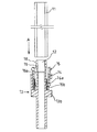
- FIG. 1 is a front view of a connector according to an embodiment of the present invention.
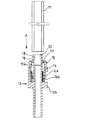
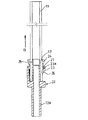
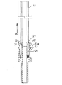
- FIG. 2 is a longitudinal sectional view showing a usage state of the connector.
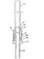
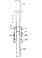
- FIG. 3 is a longitudinal sectional view showing a usage state of the connector.
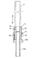
- FIG. 4 is a longitudinal sectional view showing a usage state of the connector.
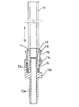
- FIG. 5 is a longitudinal sectional view showing a usage state of the connector.
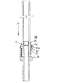
- FIG. 6 is a longitudinal sectional view showing a modification of the connector according to the present invention.
- FIG. 7 is a longitudinal sectional view showing a usage state of the connector.
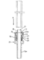
- FIG. 8 is a longitudinal sectional view showing a usage state of a connector according to another embodiment of the present invention.
- FIG. 9 is a longitudinal sectional view showing a usage state of the connector.
- FIG. 10 is a longitudinal sectional view showing a usage state of the connector.
- FIG. 11 is a longitudinal sectional view showing a usage state of the connector.
- FIG. 1 is a front view of a connector according to an embodiment of the present invention
- FIG. 2 is a longitudinal sectional view showing a use state of the connector of the present invention
- the connector 10 of the present invention includes a connector main body 13 having a mounting cylinder 12 for mounting the hose 11 and a lock member loosely fitted in the guide member 14 of the connector main body 13 so as to be slidable in the axial direction.
- the lock member 15 includes a claw member 16 erected in the direction of the attached hose facing the inner wall surface, and a protrusion 17.
- the connector main body 13 is continuously formed by a pipe portion 13a, a thick flange portion 13b, a plurality of columns 13c erected in the axial direction from the flange portion, an annular guide member 14 supported by the columns, and the pipe portion 13a. And a mounting cylinder 12 to which a hose is mounted.
- the flange portion 13b is integrally formed on the outer periphery of the pipe portion 13a.
- the support column 13 c and the guide member 14 are disposed at a predetermined distance from the mounting cylinder 12 in order to secure a storage space for the lock member 15 and the hose 11 around the mounting cylinder 12.
- the mounting cylinder 12 includes an annular first ridge 18 and a second ridge 19 on the outer periphery near the tip. Between this 1st protrusion 18 and the 2nd protrusion 19, it becomes the structure located when the protrusion 17 formed in the locking member 15 locks a hose.
- the lock member 15 has a substantially cylindrical shape, and includes a claw member 16 erected in the direction of the hose attached from the inner wall surface 15 a and a protrusion 17.
- the claw member 16 is provided at the lower end of the lock member 15 and has a configuration in which the periphery is notched and is easily elastically deformed. Further, as shown in FIGS. 2, 3 and the like, the claw member 16 has a wedge-shaped cross section from the gentle slope 16a and the horizontal surface 16b, so that it has little resistance when the hose is inserted, and is bitten when pulled out. .
- the ridge 17 is formed inside the vicinity of the upper end of the lock member 15, and when the lock member 15 is lifted, it is between the first ridge 18 and the second ridge 19 formed on the mounting cylinder 12. The hose 11 is pinched in the position.
- the hose 11 is inserted into the mounting cylinder 12 of the connector 10 from the direction of arrow A until it contacts the flange portion 13b.
- the claw member 16 of the lock member 15 contacts the outer periphery of the hose, but elastically deforms in the outer peripheral direction and is the gentle slope 16a, so that the hose 11 can be smoothly inserted (see FIGS. 2 and 3). .
- FIG. 4 shows the case where the lock member 15 is pulled directly in the direction of arrow B
- FIG. 5 shows the case where the hose 11 is pulled in the direction of arrow B.
- the connector of the present invention can be surely prevented from coming off by the claw member 16, the ridge 17, the first ridge 18, and the second ridge 19.
- the hose diameter expansion by internal pressure can be suppressed and it can adhere and seal to the connector 10 reliably. Furthermore, high sealing performance can be ensured even if the hose expands due to internal pressure. Further, a moderation feeling can be obtained by utilizing the bending of the hose.
- FIG. 6 is a longitudinal sectional view showing a modified example of the connector according to the present invention
- FIG. 7 is a longitudinal sectional view showing a usage state of the connector of the present invention.
- the lock member 15 has a substantially cylindrical shape, includes only the claw member 16 erected in the direction of the hose attached from the inner wall surface 15 a, and does not have the protrusion 17. Since other configurations are the same as those in the above-described embodiment, the same reference numerals are given and description thereof is omitted. Even if it is a case where it is comprised as mentioned above, if the hose 11 or the lock member 15 is pulled in the arrow B direction, the claw member 16 will lock the hose by biting on the hose surface by the wedge effect.
- FIG. 7 shows a case where the lock member 15 is pulled directly in the direction of arrow B. Even if the hose 11 is pulled directly in the direction of the arrow B, it can be locked.
- the connector 20 includes a connector main body 22 having a mounting cylinder 21 for mounting the hose 11, and a lock member loosely fitted in the guide member 23 of the connector main body 22 so as to be slidable in the axial direction.
- the lock member 24 includes a claw member 16 erected in the direction of the attached hose facing the inner wall surface, and a protrusion 17. Further, the same parts as those in the first embodiment are denoted by the same reference numerals and description thereof is omitted.
- the connector main body 22 is continuously formed by a pipe portion 13a, a thick flange portion 13b, a plurality of support columns 13c erected in the axial direction from the flange portion, an annular guide member 23 supported by the support columns, and the pipe portion 13a. And a mounting cylinder 21 to which a hose is mounted.
- the support column 13 c and the guide member 23 are arranged with a predetermined distance so as to secure a storage space for the lock member 24 and the hose 11 around the mounting cylinder 21.
- the mounting cylinder 21 includes an annular protrusion 25 on the outer periphery near the tip.
- the guide member 23 has a step portion 23a whose diameter changes on the inner periphery, and the inner diameter is larger above the step portion 23a and the inner diameter is smaller below. For this reason, the 2nd latching protrusion 27 formed in the outer periphery of the locking member 24 by the step part 23a is hold
- the locking member 24 includes a locking projection 26 on the outer periphery of the lower end and a second locking projection 27 having a predetermined interval in the axial direction, and the second locking projection 27 guides when the hose is locked. It is held by the step 23 a of the member 23.
- the hose 11 is inserted into the mounting cylinder 21 of the connector 20 in the direction of arrow A to the back.
- the claw member 16 of the lock member 24 is in contact with the outer periphery of the hose, but is elastically deformed in the outer peripheral direction and is a gentle slope, so that it can be smoothly inserted (see FIG. 9).
- FIG. 10 shows a case where the lock member 24 is pulled directly in the arrow B direction
- FIG. 11 shows a case where the hose 11 is pulled in the arrow B direction.
- the lock member 24 is fixed by the presence of the protrusion 17 and the protrusion 25 and the second locking protrusion 27 and the step portion 23a of the guide member 23, there is no possibility of lowering and the diameter of the hose is increased by the internal pressure. It is possible to prevent and securely fix and seal. Furthermore, high sealing performance can be ensured even if the hose expands due to internal pressure.
Landscapes
- Engineering & Computer Science (AREA)
- General Engineering & Computer Science (AREA)
- Mechanical Engineering (AREA)
- Quick-Acting Or Multi-Walled Pipe Joints (AREA)
- Joints That Cut Off Fluids, And Hose Joints (AREA)
Abstract
ホースを装着するための装着筒を有したコネクタ本体と、前記コネクタ本体の案内部材に軸線方向に摺動可能に遊嵌されたロック部材とから成り、前記ロック部材は、内壁面から対向する装着されたホース方向に立設された爪部材を備え、前記装着筒は、先端外周に突条を備え、ホースを前記装着筒に挿入した後、ホースまたはロック部材を引くと前記ロック部材が前進し、前記爪部材でホースを係止するとともに、装着筒側に設けられた突条とロック部材でホースを狭持するので、ホースの接続を容易に行うことができるとともに、高いシール性を達成することができる。
Description
この発明は、ホースを迅速かつ確実に接続することのできるコネクタに関し、例えば自動車のヘッドランプウオッシャー用ホース等に使用されるコネクタに関するものである。
従来は、例えば接続筒にホースを装着し、その外周から締結バンドで締め付けて抜け止め、水漏れを防止していた。また、特許文献1に示すように、コネクタ本体の受け口の内周面に設けられた環状凹部の内周面が開口端側に向かって縮径する傾斜内周面を有し、この環状凹部に、短円筒部の一端にフランジを有するコレットの短円筒部が遊嵌状態で配置され、このコレットの内方に、径小の短円筒部がコネクタ本体の軸心と同心状にコネクタ本体の奥部内周面から開口端側に一体に延設して配置され、この短円筒部の外周面に設けられた環状溝にシールリングが装着されて構成されている。
しかし、上記構成の従来の締結バンドを使用する場合では、作業性が悪くホースの固定に時間が掛かると云う欠点が存在した。また、確実に締結バンドが装着されているか否かの確認が必要であった。更に、特許文献1に示すものでは、使用するホースの種類や内圧の高さによっては、シールリングの存在だけでは止水性に問題が見られた。
この発明は、上記したような不都合を解消するためになされたもので、高いシール性能を実現することのできるコネクタを提供するものである。
この発明のコネクタは、ホースを装着するための装着筒を有したコネクタ本体と、前記コネクタ本体の案内部材に軸線方向に摺動可能に遊嵌されたロック部材とから成り、前記ロック部材は、内壁面に立設された爪部材を備えるとともに、前記装着筒は、先端外周に突条を備え、ホースを前記装着筒に挿入した後、ホースまたはロック部材を引くことにより前記ロック部材を前進させ、前記爪部材でホースを係止するとともに、装着筒側に設けられた突条とロック部材でホースを狭持することを特徴とする。
本発明のコネクタにおいて、前記ロック部材は、内壁面に突条を備え、前記装着筒外周の突条とロック部材内壁の突条との間にホースを介在させることにより前記ロック部材の位置ずれを防止することが好ましい。この好ましい態様によれば、前記ロック部材の前進および後退を制限するので、ロック部材の位置がずれることなく、高いシール性を維持することができる。
本発明のコネクタにおいて、前記装着筒は、先端外周に複数の突条を備え、前記ロック部の先端内壁に形成された突条が前記複数の突条の間に位置してホースを狭持固定することが好ましい。この好ましい態様によれば、ホースが高い内圧を受けてもシール性を確保できる。
本発明のコネクタにおいて、前記ロック部材は、外周に係止突起を備え、該係止突起を前記案内部材の被係止部で保持してロック部材の位置ずれを防止することが好ましい。この好ましい態様によれば、高いシール性を維持することができる。
本発明のコネクタにおいて、前記ロック部材は、内壁面に突条を備え、前記装着筒外周の突条とロック部材内壁の突条との間にホースを介在させることにより前記ロック部材の位置ずれを防止することが好ましい。この好ましい態様によれば、前記ロック部材の前進および後退を制限するので、ロック部材の位置がずれることなく、高いシール性を維持することができる。
本発明のコネクタにおいて、前記装着筒は、先端外周に複数の突条を備え、前記ロック部の先端内壁に形成された突条が前記複数の突条の間に位置してホースを狭持固定することが好ましい。この好ましい態様によれば、ホースが高い内圧を受けてもシール性を確保できる。
本発明のコネクタにおいて、前記ロック部材は、外周に係止突起を備え、該係止突起を前記案内部材の被係止部で保持してロック部材の位置ずれを防止することが好ましい。この好ましい態様によれば、高いシール性を維持することができる。
この発明によれば、ホースの接続作業を容易かつ確実に行うことができるとともに、高いシール性を達成できる。
以下、一実施の形態を示す図面に基づいて本発明を詳細に説明する。図1は本発明の一実施の形態であるコネクタの正面図、図2は本発明のコネクタの使用状態を示す縦断面図である。ここで、本発明のコネクタ10は、ホース11を装着するための装着筒12を有したコネクタ本体13と、このコネクタ本体13の案内部材14に軸線方向に摺動可能に遊嵌されたロック部材15とから成り、ロック部材15は、内壁面から対向する装着されたホース方向に立設された爪部材16と、突条17とを備えている。
コネクタ本体13は、パイプ部13aと肉厚のフランジ部13bとフランジ部から軸線方向に立設された複数の支柱13cとこの支柱によって支えられる環状の案内部材14とパイプ部13aに連続して形成され、ホースの装着される装着筒12とから構成されている。フランジ部13bは、パイプ部13aの外周に一体的に形成されている。支柱13cと案内部材14は、装着筒12の周囲にロック部材15及びホース11の収納空間を確保するべく、装着筒12と所定の距離を有して配設されている。装着筒12は、先端近傍の外周に環状の第1の突条18、第2の突条19を備えている。この第1の突条18と第2の突条19の間に、ロック部材15に形成された突条17がホースをロックした際に位置する構成となっている。
ロック部材15は、略筒状をしており、内壁面15aから装着されたホース方向に立設された爪部材16と、突条17とを備えている。爪部材16は、ロック部材15の下端に設けられるとともに周囲が切り欠かれて、弾性変形し易い構成となっている。また、爪部材16は、図2、3等に示すように緩斜面16aと水平面16bとから断面が楔形に構成されているため、ホース挿入時に抵抗が少なく、引き抜き時に噛み込む構成となっている。突条17は、ロック部材15の上端近傍の内側に形成されており、ロック部材15が上昇した際に、装着筒12に形成された第1の突条18と第2の突条19の間に位置してホース11を狭持する。
次に、以上のように構成されたコネクタ10の使用態様を図2~5に従って説明する。先ず、コネクタ10の装着筒12にホース11を、矢印A方向からフランジ部13bに当接するまで挿入する。この際、ロック部材15の爪部材16は、ホース外周に接触するが、外周方向に弾性変形するとともに緩斜面16aであるため、ホース11を円滑に挿入することができる(図2、3参照)。
その後、ホース11またはロック部材15を矢印B方向に引くと、爪部材16がホース表面に楔効果により噛み込むとともに、上昇したロック部材15の突条17が装着筒12の第1の突条18、第2の突条19間に位置して、前後からホースを狭持する。図4は、ロック部材15を直接矢印B方向に引いた場合であり、図5はホース11を矢印B方向に引いた場合である。
この様に、本発明のコネクタは、爪部材16及び突条17、第1の突条18、第2の突条19によって確実な抜け止めが実現できる。また、可撓性を有するホースであっても、内圧によるホースの拡径を抑制して、確実にコネクタ10に固着及びシールすることができる。更に、内圧でホースが拡径しても高いシール性能を確保することができる。また、ホースの撓みを利用して節度感を得ることができる。
この様に、本発明のコネクタは、爪部材16及び突条17、第1の突条18、第2の突条19によって確実な抜け止めが実現できる。また、可撓性を有するホースであっても、内圧によるホースの拡径を抑制して、確実にコネクタ10に固着及びシールすることができる。更に、内圧でホースが拡径しても高いシール性能を確保することができる。また、ホースの撓みを利用して節度感を得ることができる。
図6は、本発明に係るコネクタの変形例を示す縦断面図、図7は本発明のコネクタの使用状態を示す縦断面図である。本変形例において、ロック部材15は、略筒状をしており、内壁面15aから装着されたホース方向に立設された爪部材16のみを備えており、突条17を有していない。他の構成については上述した実施例と同一であるので、同一符号を付して説明を省略する。
以上のように構成した場合であっても、ホース11またはロック部材15を矢印B方向に引くと、爪部材16がホース表面に楔効果により噛み込にホースを係止する。また、ロック部材15が装着筒12の第1の突条18、第2の突条19上に移動するので、内圧によるホースの拡径を抑制し、シール性能を確保できる。図7は、ロック部材15を直接矢印B方向に引いた場合である。ホース11を直接矢印B方向に引いても係止できる。
以上のように構成した場合であっても、ホース11またはロック部材15を矢印B方向に引くと、爪部材16がホース表面に楔効果により噛み込にホースを係止する。また、ロック部材15が装着筒12の第1の突条18、第2の突条19上に移動するので、内圧によるホースの拡径を抑制し、シール性能を確保できる。図7は、ロック部材15を直接矢印B方向に引いた場合である。ホース11を直接矢印B方向に引いても係止できる。
図8~9は、本発明の他の実施形態であるコネクタの使用状態を示す縦断面図である。本実施の形態において、コネクタ20は、ホース11を装着するための装着筒21を有したコネクタ本体22と、このコネクタ本体22の案内部材23に軸線方向に摺動可能に遊嵌されたロック部材24とから成り、ロック部材24は、内壁面から対向する装着されたホース方向に立設された爪部材16と、突条17とを備えている。また、第1の実施形態と同一部分については、同一番号を付して説明を省略する。
コネクタ本体22は、パイプ部13aと肉厚のフランジ部13bとフランジ部から軸線方向に立設された複数の支柱13cと支柱によって支えられる環状の案内部材23とパイプ部13aに連続して形成され、ホースの装着される装着筒21とから構成されている。支柱13cと案内部材23は、装着筒21の周囲にロック部材24及びホース11の収納空間を確保するべく、所定の距離を有して配設されている。装着筒21は、先端近傍の外周に環状の突条25を備えている。
案内部材23は、内周に径の変化する段部23aを有しており、この段部23aより上で内径が大きく、下で内径が小さく形成されている。このため、段部23aでロック部材24の外周に形成された第2の係止突起27をロック時に保持する。なお、第2の係止突起27は、段部を有さない案内部材23の被係止部で保持してもよい。
ロック部材24は、下端外周に係止突起26と軸線方向に所定の間隔を有して第2の係止突起27を備えており、ホースをロックした際に第2の係止突起27が案内部材23の段部23aで保持される。
次に、以上のように構成されたコネクタ20の使用態様を図8~11に従って説明する。先ず、コネクタ20の装着筒21にホース11を、矢印A方向へ奥まで挿入する。この際、ロック部材24の爪部材16は、ホース外周に接触するが、外周方向に弾性変形するとともに緩斜面であるため、円滑に挿入することができる(図9参照)。
その後、ホース11またはロック部材24を矢印B方向に引くと、爪部材16がホース表面に楔効果により噛み込むとともに、ホースとともに上昇したロック部材24の突条17が装着筒21の突条25よりホース挿入方向に位置して、前後からホースを狭持する。図10は、ロック部材24を直接矢印B方向に引いた場合であり、図11はホース11を矢印B方向に引いた場合である。
この様に、本発明のコネクタは、爪部材16及び突条17、突条25によって確実な抜け止めが実現できる。また、ロック部材24は、突条17と突条25及び第2の係止突起27と案内部材23の段部23aの存在により固定されるので、下降する虞がなく、内圧によるホースの拡径を抑制して、確実に固着及びシールすることができる。更に、内圧でホースが拡径しても高いシール性能を確保することができる。
この様に、本発明のコネクタは、爪部材16及び突条17、突条25によって確実な抜け止めが実現できる。また、ロック部材24は、突条17と突条25及び第2の係止突起27と案内部材23の段部23aの存在により固定されるので、下降する虞がなく、内圧によるホースの拡径を抑制して、確実に固着及びシールすることができる。更に、内圧でホースが拡径しても高いシール性能を確保することができる。
更に、本発明は上述の実施例に限定されることなく、特許請求の範囲の記載に基づいて種々の設計変更が可能である。
2011年5月12日に出願された日本特許出願第2011-106902号の明細書、特許請求の範囲、図面及び要約書の全内容をここに引用し、本発明の明細書の開示として、取り入れるものである。
2011年5月12日に出願された日本特許出願第2011-106902号の明細書、特許請求の範囲、図面及び要約書の全内容をここに引用し、本発明の明細書の開示として、取り入れるものである。
Claims (4)
- ホースを装着するための装着筒を有したコネクタ本体と、前記コネクタ本体の案内部材に軸線方向に摺動可能に遊嵌されたロック部材とから成り、
前記ロック部材は、内壁面に立設された爪部材を備えるとともに、前記装着筒は、先端外周に突条を備え、ホースを前記装着筒に挿入した後、ホースまたはロック部材を引くことにより前記ロック部材を前進させ、前記爪部材でホースを係止するとともに、装着筒側に設けられた突条とロック部材でホースを狭持することを特徴とするコネクタ。 - 前記ロック部材は、内壁面に突条を備え、前記装着筒外周の突条とロック部材内壁の突条との間にホースを介在させることにより前記ロック部材の位置ずれを防止することを特徴とする請求項1に記載のコネクタ。
- 前記装着筒は、先端外周に複数の突条を備え、前記ロック部の先端内壁に形成された突条が前記複数の突条の間に位置してホースを狭持固定することを特徴とする請求項1または2に記載のコネクタ。
- 前記ロック部材は、外周に係止突起を備え、該係止突起を前記案内部材の被係止部で保持してロック部材の位置ずれを防止することを特徴とする請求項1から請求項3の何れか1項に記載のコネクタ。
Priority Applications (2)
| Application Number | Priority Date | Filing Date | Title |
|---|---|---|---|
| US14/116,214 US9016728B2 (en) | 2011-05-12 | 2012-05-10 | Connector |
| CN201280034327.XA CN103649611B (zh) | 2011-05-12 | 2012-05-10 | 连接器 |
Applications Claiming Priority (2)
| Application Number | Priority Date | Filing Date | Title |
|---|---|---|---|
| JP2011106902A JP5896370B2 (ja) | 2011-05-12 | 2011-05-12 | コネクタ |
| JP2011-106902 | 2011-05-12 |
Publications (1)
| Publication Number | Publication Date |
|---|---|
| WO2012153811A1 true WO2012153811A1 (ja) | 2012-11-15 |
Family
ID=47139286
Family Applications (1)
| Application Number | Title | Priority Date | Filing Date |
|---|---|---|---|
| PCT/JP2012/062034 Ceased WO2012153811A1 (ja) | 2011-05-12 | 2012-05-10 | コネクタ |
Country Status (4)
| Country | Link |
|---|---|
| US (1) | US9016728B2 (ja) |
| JP (1) | JP5896370B2 (ja) |
| CN (1) | CN103649611B (ja) |
| WO (1) | WO2012153811A1 (ja) |
Families Citing this family (3)
| Publication number | Priority date | Publication date | Assignee | Title |
|---|---|---|---|---|
| WO2012123827A2 (en) * | 2011-03-13 | 2012-09-20 | Netafim Ltd | Irrigation pipe coupler |
| ES2702615A1 (es) * | 2017-09-04 | 2019-03-04 | Bsh Electrodomesticos Espana Sa | Dispositivo de union y campo de coccion a gas |
| DE102017215896A1 (de) * | 2017-09-08 | 2019-03-14 | Mahle International Gmbh | Schlauchverbindung mit Elastomerschlauch |
Citations (5)
| Publication number | Priority date | Publication date | Assignee | Title |
|---|---|---|---|---|
| JPH0377893U (ja) * | 1989-10-04 | 1991-08-06 | ||
| JPH07151282A (ja) * | 1993-12-01 | 1995-06-13 | Usui Internatl Ind Co Ltd | 樹脂チューブ接続用継手 |
| JP2000170976A (ja) * | 1998-12-08 | 2000-06-23 | Sekisui Chem Co Ltd | 管継手 |
| JP2001021087A (ja) * | 1999-07-08 | 2001-01-26 | Sekisui Chem Co Ltd | 管継手 |
| JP2006220186A (ja) * | 2005-02-09 | 2006-08-24 | Toyox Co Ltd | ホース継手 |
Family Cites Families (7)
| Publication number | Priority date | Publication date | Assignee | Title |
|---|---|---|---|---|
| JPS48108215U (ja) * | 1972-03-18 | 1973-12-14 | ||
| CN87211263U (zh) * | 1987-10-09 | 1988-06-01 | 杨宗德 | 拉卡式塑料管快速接头 |
| JP2779866B2 (ja) * | 1990-03-23 | 1998-07-23 | ニッタ・ムアー株式会社 | 管継手 |
| JP3078731B2 (ja) * | 1995-08-04 | 2000-08-21 | 株式会社ナニワ製作所 | 樹脂チューブ用金属製管継手 |
| US6416085B1 (en) * | 2000-10-16 | 2002-07-09 | Branimir Markovic | Pressurized hose coupling |
| DE102006015158B4 (de) * | 2006-03-30 | 2009-10-29 | Kaimer Gmbh & Co. Holding Kg | Steckverbinder |
| CN201386876Y (zh) * | 2008-12-19 | 2010-01-20 | 安徽中鼎金亚汽车管件制造有限公司 | 汽车油管连接机构 |
-
2011
- 2011-05-12 JP JP2011106902A patent/JP5896370B2/ja active Active
-
2012
- 2012-05-10 WO PCT/JP2012/062034 patent/WO2012153811A1/ja not_active Ceased
- 2012-05-10 CN CN201280034327.XA patent/CN103649611B/zh not_active Expired - Fee Related
- 2012-05-10 US US14/116,214 patent/US9016728B2/en not_active Expired - Fee Related
Patent Citations (5)
| Publication number | Priority date | Publication date | Assignee | Title |
|---|---|---|---|---|
| JPH0377893U (ja) * | 1989-10-04 | 1991-08-06 | ||
| JPH07151282A (ja) * | 1993-12-01 | 1995-06-13 | Usui Internatl Ind Co Ltd | 樹脂チューブ接続用継手 |
| JP2000170976A (ja) * | 1998-12-08 | 2000-06-23 | Sekisui Chem Co Ltd | 管継手 |
| JP2001021087A (ja) * | 1999-07-08 | 2001-01-26 | Sekisui Chem Co Ltd | 管継手 |
| JP2006220186A (ja) * | 2005-02-09 | 2006-08-24 | Toyox Co Ltd | ホース継手 |
Also Published As
| Publication number | Publication date |
|---|---|
| JP5896370B2 (ja) | 2016-03-30 |
| US20140103639A1 (en) | 2014-04-17 |
| CN103649611B (zh) | 2017-03-15 |
| JP2012237380A (ja) | 2012-12-06 |
| CN103649611A (zh) | 2014-03-19 |
| US9016728B2 (en) | 2015-04-28 |
Similar Documents
| Publication | Publication Date | Title |
|---|---|---|
| CN100482999C (zh) | 管道的连接装置 | |
| JP3825278B2 (ja) | グロメット | |
| KR101335080B1 (ko) | 와이어 하네스용 그로밋 | |
| CN103765074B (zh) | 连接器 | |
| JP5099549B2 (ja) | 管接続構造 | |
| CN102691836B (zh) | 管接头 | |
| JP4929005B2 (ja) | フレキシブル管用継手のシール方法およびシール構造 | |
| WO2012153811A1 (ja) | コネクタ | |
| JP2011223747A (ja) | グロメット | |
| US20210172524A1 (en) | Gasket | |
| JP4949061B2 (ja) | 管継手 | |
| JP2011188619A (ja) | ワイヤハーネス用のグロメット | |
| JP2006038169A (ja) | 管継手 | |
| JP5193569B2 (ja) | フレキシブル管用継手 | |
| JP4948884B2 (ja) | 流体管の移動防止手段 | |
| JP4948883B2 (ja) | 流体管の移動防止手段 | |
| JP5037035B2 (ja) | 流体管の移動防止手段 | |
| JP4873604B2 (ja) | 管継手 | |
| JP5724740B2 (ja) | グロメット | |
| JP5427378B2 (ja) | フレキシブル管用継手 | |
| JP5484767B2 (ja) | 移動防止手段 | |
| KR101021410B1 (ko) | 접속 금구 및 이를 이용한 튜브와 호스의 연결구조 | |
| JP2008002498A (ja) | グロメット | |
| JP5380587B2 (ja) | フレキシブル管用継手 | |
| HK1176984A1 (zh) | 管接头 |
Legal Events
| Date | Code | Title | Description |
|---|---|---|---|
| 121 | Ep: the epo has been informed by wipo that ep was designated in this application |
Ref document number: 12782280 Country of ref document: EP Kind code of ref document: A1 |
|
| NENP | Non-entry into the national phase |
Ref country code: DE |
|
| WWE | Wipo information: entry into national phase |
Ref document number: 14116214 Country of ref document: US |
|
| 122 | Ep: pct application non-entry in european phase |
Ref document number: 12782280 Country of ref document: EP Kind code of ref document: A1 |