WO2012153592A1 - 等速自在継手 - Google Patents
等速自在継手 Download PDFInfo
- Publication number
- WO2012153592A1 WO2012153592A1 PCT/JP2012/059785 JP2012059785W WO2012153592A1 WO 2012153592 A1 WO2012153592 A1 WO 2012153592A1 JP 2012059785 W JP2012059785 W JP 2012059785W WO 2012153592 A1 WO2012153592 A1 WO 2012153592A1
- Authority
- WO
- WIPO (PCT)
- Prior art keywords
- joint member
- velocity universal
- constant velocity
- universal joint
- bellows
- Prior art date
Links
Images


Classifications
-
- F—MECHANICAL ENGINEERING; LIGHTING; HEATING; WEAPONS; BLASTING
- F16—ENGINEERING ELEMENTS AND UNITS; GENERAL MEASURES FOR PRODUCING AND MAINTAINING EFFECTIVE FUNCTIONING OF MACHINES OR INSTALLATIONS; THERMAL INSULATION IN GENERAL
- F16D—COUPLINGS FOR TRANSMITTING ROTATION; CLUTCHES; BRAKES
- F16D3/00—Yielding couplings, i.e. with means permitting movement between the connected parts during the drive
- F16D3/84—Shrouds, e.g. casings, covers; Sealing means specially adapted therefor
- F16D3/843—Shrouds, e.g. casings, covers; Sealing means specially adapted therefor enclosed covers
- F16D3/845—Shrouds, e.g. casings, covers; Sealing means specially adapted therefor enclosed covers allowing relative movement of joint parts due to the flexing of the cover
-
- F—MECHANICAL ENGINEERING; LIGHTING; HEATING; WEAPONS; BLASTING
- F16—ENGINEERING ELEMENTS AND UNITS; GENERAL MEASURES FOR PRODUCING AND MAINTAINING EFFECTIVE FUNCTIONING OF MACHINES OR INSTALLATIONS; THERMAL INSULATION IN GENERAL
- F16D—COUPLINGS FOR TRANSMITTING ROTATION; CLUTCHES; BRAKES
- F16D3/00—Yielding couplings, i.e. with means permitting movement between the connected parts during the drive
- F16D3/16—Universal joints in which flexibility is produced by means of pivots or sliding or rolling connecting parts
- F16D3/20—Universal joints in which flexibility is produced by means of pivots or sliding or rolling connecting parts one coupling part entering a sleeve of the other coupling part and connected thereto by sliding or rolling members
- F16D3/22—Universal joints in which flexibility is produced by means of pivots or sliding or rolling connecting parts one coupling part entering a sleeve of the other coupling part and connected thereto by sliding or rolling members the rolling members being balls, rollers, or the like, guided in grooves or sockets in both coupling parts
- F16D3/223—Universal joints in which flexibility is produced by means of pivots or sliding or rolling connecting parts one coupling part entering a sleeve of the other coupling part and connected thereto by sliding or rolling members the rolling members being balls, rollers, or the like, guided in grooves or sockets in both coupling parts the rolling members being guided in grooves in both coupling parts
- F16D3/2237—Universal joints in which flexibility is produced by means of pivots or sliding or rolling connecting parts one coupling part entering a sleeve of the other coupling part and connected thereto by sliding or rolling members the rolling members being balls, rollers, or the like, guided in grooves or sockets in both coupling parts the rolling members being guided in grooves in both coupling parts where the grooves are composed of radii and adjoining straight lines, i.e. undercut free [UF] type joints
Definitions
- the present invention is suitable for, for example, a fixed type constant velocity universal joint incorporated in a drive shaft of an automobile, particularly a front wheel drive shaft, and includes a boot that prevents foreign matter from entering from the outside of the joint and lubricant leakage from the inside of the joint. It relates to a constant velocity universal joint.
- constant velocity universal joints that are used as means for transmitting rotational force from an automobile engine to wheels at a constant speed: a fixed constant velocity universal joint and a sliding constant velocity universal joint. Both of these constant velocity universal joints have a structure in which two shafts on the driving side and the driven side are connected so that rotational torque can be transmitted at a constant speed even if the two shafts have an operating angle.
- the drive shaft that transmits power from the engine of the automobile to the driving wheel needs to correspond to the angular displacement and axial displacement due to the change in the relative positional relationship between the engine and the wheel, the engine side (inboard side) ) And a fixed type constant velocity universal joint on the drive wheel side (outboard side), and both constant velocity universal joints are connected by an intermediate shaft.
- the boot has a large-diameter end fastened to the outer peripheral surface of the opening of the outer joint member, a small-diameter end fastened to the outer peripheral surface of the intermediate shaft extending from the inner joint member, a large-diameter end, and a small-diameter end. And a bellows portion having a diameter reduced from the large diameter end portion toward the small diameter end portion. Since this constant velocity universal joint has a function of rotating while taking an operating angle, this boot has a bellows shape that can be expanded and contracted in order to ensure flexibility that can follow its behavior (see, for example, Patent Document 1). ).
- the bellows-shaped boot disclosed in Patent Document 1 described above has a uniform annular shape on at least one of two annular side surfaces of at least one of the plurality of annular folds.
- the structure has a plurality of raised portions protruding from the side surface or a plurality of recessed portions recessed.
- the opposed annular side surfaces of two adjacent annular folds are held at positions separated from each other by the ridges, and are not rubbed against each other on a plane by the recesses. It is designed to reduce the generation of noise, especially under wet rain conditions.
- the present invention has been proposed in view of the above-described problems, and the object of the present invention is to reliably eliminate the scratching noise generated by the contact between the bellows portions when rotating with the operating angle taken.
- An object of the present invention is to provide a constant velocity universal joint that can be suppressed.
- the present invention provides torque while allowing angular displacement between an outer joint member having an opening at one end and a torque transmission member between the outer joint member.
- a constant velocity universal joint comprising: an inner joint member for transmission; and an end portion of the bellows-like boot that closes the opening of the outer joint member fastened and fixed to the opening of the outer joint member and a shaft member extending from the inner joint member.
- the boot connects the large-diameter end fastened to the outer peripheral surface of the opening of the outer joint member and the small-diameter end fastened and fixed to the outer peripheral surface of the shaft member, and connects the large-diameter end to the small-diameter end.
- the boot of the present invention is preferably made of a resin made of a thermoplastic polyester elastomer.
- “at least a pair of adjacent slopes of the bellows portion” includes all adjacent slopes such as two pairs of adjacent slopes and three pairs of adjacent slopes in addition to the pair of adjacent slopes. Means.
- the boot rotates while deforming with the outer joint member and the inner joint member taking an operating angle.
- the grid-like convex portions provided on both the adjacent slopes come into contact with each other, and the contact area can be greatly reduced. . Therefore, it is possible to reliably suppress the rubbing sound that occurs when the inclined surfaces of the bellows portions come into contact with each other, and it is possible to ensure a long duration in which the rubbing sound does not occur.
- the bellows portion according to the present invention has a pair of slopes or a small diameter end portion in which five peak portions are formed along the joint axial direction and connects the second peak portion and the third peak portion from the small diameter end portion. It is preferable that at least one of the pair of slopes connecting the third peak and the fourth peak is provided with a grid-like convex part.
- the bellows part in which the five peak parts are formed along the joint axial direction the second peak part, the third peak part, and the fourth peak part 4 from the small diameter end part when rotating with the operating angle taken. Since the first ridge is greatly deformed, a pair of slopes connecting these ridges are likely to come into contact with each other and cause relative movement (stick-slip). In addition, it is possible to further reliably suppress the rubbing sound generated by the contact between the inclined surfaces of the bellows portions, and to ensure a long duration in which the rubbing sound does not occur.
- a pair of slopes connecting the second peak and the third peak from the end of the small diameter, or connecting the third peak and the fourth peak from the end of the small diameter At least one of the pair of slopes” means that when a grid-like convex portion is provided only on a pair of slopes connecting the second peak and the third peak from the small diameter end, When providing a grid-like convex part only on a pair of slopes connecting the first peak and the fourth peak, a pair connecting the second peak and the third peak from the small diameter end This includes the case where a grid-like convex portion is provided on both of the slope and the pair of slopes connecting the third peak and the fourth peak from the small-diameter end.
- the convex portions in the present invention are preferably formed so as to extend in a lattice shape with an inclination angle with respect to the joint axial direction.
- the convex portions in the present invention are preferably formed in a lattice shape with adjacent intervals of 2 mm or more and 6 mm or less. If it does in this way, the rubbing sound which generate
- the interval between adjacent protrusions is smaller than 2 mm, the lattice shape becomes too fine, and it becomes difficult to obtain the effect of suppressing the scratching sound.
- the convex portion in the present invention is preferably formed at a height of 0.2 mm to 0.6 mm from the slope. If it does in this way, the rubbing sound which generate
- the height of the convex part is smaller than 0.2 mm, when the slopes adjacent to the bellows part are close to each other with an operating angle, the slopes that are concave parts other than the convex part come into contact with the adjacent slopes. Therefore, it becomes difficult to obtain the effect of suppressing the scratching sound.
- the height of the convex portion is larger than 0.6 mm, the boot formability and the moldability are lowered.
- the convex portion in the present invention is preferably formed such that the tip width dimension in contact with the adjacent slope is 1/3 or less of the adjacent interval. If it does in this way, the rubbing sound which generate
- the tip width dimension of the convex part that contacts the adjacent slope is larger than 1/3 of the adjacent interval, the total contact area of the convex part tip that contacts the adjacent slope becomes large, so the effect of suppressing fretting noise is obtained. It becomes difficult to obtain.
- the present invention relates to an outer joint member in which a plurality of arc-shaped track grooves extending in the axial direction are formed on a spherical inner peripheral surface, and a plurality of arc-shaped members on a spherical outer peripheral surface in pairs with the track grooves of the outer joint member.
- the track groove of the outer joint member is held by a cage disposed between the inner joint member formed with the track groove and the spherical inner peripheral surface of the outer joint member and the spherical outer peripheral surface of the inner joint member.
- the boot rotates while the outer joint member and the inner joint member take an operating angle.
- the grid-like convex portions provided on both adjacent slopes come into contact with each other, and the contact area is greatly reduced. Can do. Therefore, it is possible to reliably suppress the rubbing sound that occurs when the inclined surfaces of the bellows portions come into contact with each other, and it is possible to ensure a long duration in which the rubbing sound does not occur.
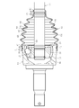
- it is a front view which shows the constant velocity universal joint of the state which mounted
- it is an expanded sectional view which illustrates the shape of a lattice-like convex part.
- it is an expanded sectional view which illustrates the shape of a lattice-like convex part.
- it is an expanded sectional view which illustrates the shape of a lattice-like convex part.
- it is an expanded sectional view which illustrates the height in a grid
- a fixed constant velocity is provided that is incorporated in a drive shaft of an automobile and has a structure in which two shafts on a driving side and a driven side are connected to transmit rotational torque at a constant speed even when the two shafts have an operating angle.
- An undercut-free constant velocity universal joint which is one of universal joints, will be exemplified.
- the present invention can also be applied to other fixed type constant velocity universal joints such as a Rzeppa type constant velocity universal joint, a double offset type constant velocity universal joint, a cross groove type constant velocity universal joint, a tripod type, and the like.
- the present invention can also be applied to a sliding type constant velocity universal joint such as a speed universal joint.
- the undercut-free type constant velocity universal joint of the embodiment shown in FIG. 2 includes an outer joint member 10 in which a plurality of arc-shaped track grooves 11 extending in the axial direction are formed on the spherical inner peripheral surface 12 at equal intervals in the circumferential direction.
- the inner joint member 20 having a plurality of arc-shaped track grooves 21 formed on the spherical outer peripheral surface 22 in pairs with the track grooves 11 of the outer joint member 10, and the track grooves 11 and the inner joint members of the outer joint member 10.
- a ball 30 serving as a torque transmitting member interposed between the 20 track grooves 21 and a spherical inner peripheral surface 12 of the outer joint member 10 and a spherical outer peripheral surface 22 of the inner joint member 20.
- the main part is comprised with the cage 40 holding 30.
- the opening side portion of the track groove 11 of the outer joint member 10 and the back side portion of the track groove 21 of the inner joint member 20 are formed in a straight shape parallel to the joint axial direction so as to increase the operating angle. Yes.
- One end of an intermediate shaft 50 that is a shaft member is connected to the shaft hole of the inner joint member 20 by spline fitting.
- An inner joint member of a sliding type constant velocity universal joint (not shown) is connected to the other end of the intermediate shaft 50 by spline fitting.
- This type of constant velocity universal joint has a bellows shape between the outer joint member 10 and the intermediate shaft 50 in order to prevent leakage of a lubricant such as grease enclosed in the joint and to prevent foreign matter from entering from the outside of the joint.
- the boot 60 is attached, and the opening 13 of the outer joint member 10 is closed with the boot 60.
- the lubricity during the operation in which the intermediate shaft 50 rotates while taking an operating angle with respect to the outer joint member 10 is ensured. I have to.
- the boot 60 is fastened and fixed to the outer peripheral surface of the opening 13 of the outer joint member 10 by the boot band 71 and the outer peripheral surface of the intermediate shaft 50 extending from the inner joint member 20 by the boot band 72.
- the small-diameter end portion 62 is connected to the large-diameter end portion 61 and the small-diameter end portion 62, and the bellows portion 63 is reduced in diameter from the large-diameter end portion 61 toward the small-diameter end portion 62. Since the constant velocity universal joint has a function of rotating while taking an operating angle, the boot 60 has a bellows shape that can be expanded and contracted in order to ensure flexibility to follow the behavior.
- the bellows portion 63 in which the five peak portions 64 are formed along the joint axis direction is illustrated, but the number thereof is arbitrary.
- two pairs of adjacent slopes 66 of the bellows portion 63 of the boot 60 that is, a second peak portion 64 and a third peak portion 64 from the small diameter end portion 62, And a pair of slopes 66 connecting the third peak portion 64 and the fourth peak portion 64 from the small-diameter end portion 62 with an inclination angle ⁇ with respect to the joint axis direction.
- a grid-like convex portion 67 is provided.
- the boot 60 in a state in which the outer joint member 10 and the inner joint member 20 take an operating angle.
- the lattice-like convex parts 67 provided on both the adjacent slopes 66 come into contact with each other.
- the contact area can be greatly reduced. For this reason, it is possible to reliably suppress the rubbing noise that occurs when the inclined surfaces 66 of the bellows portion 63 are in contact with each other, and to ensure a long duration during which the rubbing noise does not occur.
- the effect of suppressing the scratching noise generated by the contact between the inclined surfaces 66 of the bellows part 63 is that the constant velocity universal joint having a maximum operating angle exceeding 40 °, that is, the constant velocity universal where the deformation of the bellows part 63 of the boot 60 is large. Even when applied to a joint, it is sufficiently exerted, but even when applied to a constant velocity universal joint having a maximum operating angle smaller than 40 °, that is, a constant velocity universal joint in which the deformation of the bellows portion 63 of the boot 60 is small. If the inclined surface 66 of the bellows portion 63 comes into contact, the effect of suppressing the rubbing noise can be exhibited.
- the second peak part 64 and the third peak part 64 from the small diameter end part 62 when rotating with the operating angle taken. Since the peak portion 64 and the fourth peak portion 64 are greatly deformed, the two pairs of slopes 66 connecting the peak portions 64 are in contact with each other and are likely to cause relative movement (stick slip).
- the grid-like convex portions 67 on the slopes 66 it is possible to more reliably suppress the scratching sound that occurs when the slopes 66 of the bellows part 63 are in contact with each other, and to increase the duration during which the scratching noise does not occur. Can be secured.
- a convex portion 67 may be provided.
- the lattice-shaped convex portions 67 may be formed so as to extend in a direction parallel to and perpendicular to the joint axis direction, but as in this embodiment, the lattice-like convex portions 67 are 45 to the joint axis direction. It is formed so as to be inclined at an angle ⁇ of °. In this way, when the pair of adjacent inclined surfaces 66 of the bellows portion 63 are in contact with each other by inclining at an angle ⁇ of 45 °, the relative positions of the lattice-like convex portions 67 on the contacting inclined surfaces 66 do not coincide with each other. It becomes easy to make. In addition, the contact area can be greatly reduced easily, and it is possible to more reliably suppress the noise generated when the bellows parts 63 are in contact with each other, and to ensure a long duration during which the noise is not generated. .
- the cross-sectional shape of the grid-like convex portion 67 can be various shapes such as a rectangle, a triangle, a trapezoid, and an ellipse, and the shape is arbitrary.
- the convex part 67 is formed in the grid
- the adjacent interval t between the convex portions 67 is smaller than 2 mm, the lattice shape becomes too fine, and it becomes difficult to obtain the effect of suppressing the scratching sound.
- the adjacent interval t of the convex portions 67 is larger than 6 mm, when the adjacent inclined surfaces 66 of the bellows portion 63 come close to each other with an operating angle, the inclined surfaces 66 other than the convex portion 67 contact the adjacent inclined surfaces 66. Therefore, it becomes difficult to obtain the effect of suppressing the scratching sound.
- the lattice-like convex portion 67 (the cross-sectional shape is exemplified as a trapezoid) is formed with a height h of 0.2 mm or more and 0.6 mm or less from the slope 66.
- the height h of the convex portion 67 from the inclined surface 66 is set to 0.2 mm or more and 0.6 mm or less, it is possible to effectively suppress the noise generated when the inclined surfaces 66 of the bellows portion 63 contact each other. It is possible to ensure a long duration in which no scratching sound is generated.
- the height h of the convex portion 67 is smaller than 0.2 mm, when the adjacent inclined surfaces 66 of the bellows portion 63 come close to each other with an operating angle, the inclined surfaces 66 other than the convex portion 67 are adjacent to each other. It becomes difficult to obtain the effect of suppressing scratching noise. On the contrary, if the height h of the convex part 67 is larger than 0.6 mm, the moldability of the boot 60 is lowered and the workability of the molding die is lowered.
- the lattice-shaped convex portion 67 (the cross-sectional shape is exemplified as a trapezoid) has a tip width dimension w that contacts the adjacent inclined surface 66 of 1/3 or less, preferably 1/4 or less of the adjacent interval t. It is formed to become.
- the leading end width dimension w of the convex portion 67 includes a dimension in a state where the leading end portion is deformed when the convex portion 67 contacts the adjacent slope 66.
- the tip width dimension w of the convex portion 67 that contacts the adjacent slope 66 is larger than 1/3 of the adjacent interval t, the contact area when the tip of the convex portion 67 contacts the adjacent slope 66 is large. Therefore, it becomes difficult to obtain the effect of suppressing the scratching sound.
- the boot 60 used in this embodiment is made of a resin made of a thermoplastic polyester elastomer.
- This thermoplastic polyester elastomer has a hardness of 35 or more and 53 or less according to JIS K6253 according to a type D durometer, and is blended with an additive for preventing scratch noise.
- “HO (RO) ⁇ H” R: a functional group obtained by removing 2 hydrogen from a hydrocarbon compound having 1 to 6 carbon atoms, x: an integer of 1 to 1000
- a thermoplastic polyester elastomer containing 0.01 to 1.5 parts by weight of the compound represented by the formula is preferred.
Landscapes
- Engineering & Computer Science (AREA)
- General Engineering & Computer Science (AREA)
- Mechanical Engineering (AREA)
- Sealing Devices (AREA)
- Diaphragms And Bellows (AREA)
Abstract
一端に開口部を有する外側継手部材10と、その外側継手部材10との間でボールを介して角度変位を許容しながらトルクを伝達する内側継手部材20とを備え、外側継手部材10の開口部を閉塞する蛇腹状のブーツ60の端部61,62を、外側継手部材10の開口部と内側継手部材20から延びるシャフト50とにそれぞれ締め付け固定した等速自在継手であって、ブーツ60は、外側継手部材10の開口部の外周面に締め付け固定された大径端部61とシャフト50の外周面に締め付け固定された小径端部62とを繋ぎ、大径端部61から小径端部62へ向けて縮径した伸縮自在な蛇腹部63を備え、蛇腹部63の隣接する山部64を繋ぐ二対の斜面66に格子状の凸部67を設ける。
Description
本発明は、例えば自動車のドライブシャフト、特に前輪ドライブシャフト用に組み込まれる固定式等速自在継手などに好適で、継手外部からの異物侵入や継手内部からの潤滑剤漏洩を防止するブーツを備えた等速自在継手に関する。
例えば、自動車のエンジンから車輪に回転力を等速で伝達する手段として使用される等速自在継手には、固定式等速自在継手と摺動式等速自在継手の二種がある。これら両者の等速自在継手は、駆動側と従動側の二軸を連結してその二軸が作動角をとっても等速で回転トルクを伝達し得る構造を備えている。
自動車のエンジンから駆動車輪に動力を伝達するドライブシャフトは、エンジンと車輪との相対的位置関係の変化による角度変位と軸方向変位に対応する必要があるため、一般的にエンジン側(インボード側)に摺動式等速自在継手を、駆動車輪側(アウトボード側)に固定式等速自在継手をそれぞれ装備し、両者の等速自在継手を中間シャフトで連結した構造を具備する。
これら摺動式等速自在継手あるいは固定式等速自在継手では、継手内部に封入されたグリース等の潤滑剤の漏洩を防ぐと共に継手外部からの異物侵入を防止するため、等速自在継手の外側継手部材と中間シャフトとの間に蛇腹状ブーツを装着して、外側継手部材の開口部をブーツで閉塞した構造が一般的である。
ブーツは、外側継手部材の開口部の外周面に締め付け固定された大径端部と、内側継手部材から延びる中間シャフトの外周面に締め付け固定された小径端部と、大径端部と小径端部とを繋ぎ、その大径端部から小径端部へ向けて縮径した蛇腹部とで構成されている。このブーツは、等速自在継手が作動角をとりながら回転する機能を備えていることから、その挙動に追従できる柔軟性を確保するために伸縮自在な蛇腹形状としている(例えば、特許文献1参照)。
ところで、従来の等速自在継手においては、クロロプレンゴム等のゴム製ブーツが使用されていたが、ゴム製ブーツに比べて耐久性に優れる熱可塑性エラストマー材を使用した樹脂製ブーツが広く使用されるようになっている。しかしながら、樹脂製ブーツは、等速自在継手が高作動角にて回転すると、蛇腹部同士が接触することにより擦れ音(擦過音)が発生することがある。特に、樹脂製ブーツの表面が水に濡れた状態では、大きな擦過音が発生する場合もある。
この擦過音に関する問題を解消するため、前述の特許文献1に開示された蛇腹状ブーツでは、複数の環状折り目のうちの少なくとも1つにおける2つの環状側面のうち少なくとも一方の面に、均一な環状側面から突出する複数の隆起部または引っ込んだ複数の凹部を有する構造としている。この特許文献1では、継手の回転時、2つの隣接する環状折り目の対向する環状側面が、隆起部により互いに離れた位置に保持され、また、凹部により平面で互いに擦り合わないようにすることで、特に湿った雨の状況下で騒音の発生を低減するようにしている。
しかしながら、特許文献1に開示された蛇腹状ブーツでは、高作動角をとると、蛇腹部の変形が大きくなるため、隣接する2つの環状側面のうち、隆起部あるいは凹部が形成された一方の環状側面の隆起部あるいは凹部以外の部分が、もう一方の環状側面に接触してしまうので、隣接する2つの環状側面間での接触面積が大きくなり、擦過音の発生を防止する効果が十分に得られない。この2つの環状側面の接触部分間に水が介在すると、その擦過音の抑制効果がより一層顕著に低下する。
そこで、本発明は前述の問題点に鑑みて提案されたもので、その目的とするところは、作動角をとった状態で回転する際に蛇腹部同士が接触することにより発生する擦過音を確実に抑制し得る等速自在継手を提供することにある。
前述の目的を達成するための技術的手段として、本発明は、一端に開口部を有する外側継手部材と、その外側継手部材との間でトルク伝達部材を介して角度変位を許容しながらトルクを伝達する内側継手部材とを備え、外側継手部材の開口部を閉塞する蛇腹状ブーツの端部を、外側継手部材の開口部と内側継手部材から延びる軸部材とにそれぞれ締め付け固定した等速自在継手であって、ブーツは、外側継手部材の開口部の外周面に締め付け固定された大径端部と軸部材の外周面に締め付け固定された小径端部とを繋ぎ、大径端部から小径端部へ向けて縮径した伸縮自在な蛇腹部を備え、蛇腹部の少なくとも一対の隣接する斜面に格子状の凸部を設けたことを特徴とする。なお、本発明のブーツは、熱可塑性ポリエステル系エラストマーからなる樹脂製であることが望ましい。
ここで、「蛇腹部の少なくとも一対の隣接する斜面」とは、一対の隣接する斜面以外に、二対の隣接する斜面や三対の隣接する斜面などのように全ての隣接する斜面を含むことを意味する。
本発明では、ブーツの蛇腹部の少なくとも一対の隣接する斜面に格子状の凸部を設けたことにより、外側継手部材と内側継手部材が作動角をとった状態でブーツが変形しながら回転する際に、蛇腹部の一対の隣接する斜面同士が近接しても、隣接する両方の斜面に設けられた格子状の凸部同士が接触することになってその接触面積を大幅に低減することができる。そのため、蛇腹部の斜面同士が接触することにより発生する擦過音を確実に抑制でき、その擦過音が発生しない持続時間を長く確保することができる。
また、ブーツ表面に水が付着した状態で回転する際も、隣接する斜面に設けられた格子状の凸部以外の凹状部分で水を保持することができるので、この場合も、蛇腹部の斜面同士が接触することにより発生する擦過音を確実に抑制でき、その擦過音が発生しない持続時間を長く確保することができる。
本発明における蛇腹部は、5つの山部が継手軸方向に沿って形成され、小径端部から2つ目の山部と3つ目の山部とを繋ぐ一対の斜面、あるいは、小径端部から3つ目の山部と4つ目の山部とを繋ぐ一対の斜面のうち少なくとも一方に格子状の凸部を設けることが望ましい。5つの山部が継手軸方向に沿って形成された蛇腹部の場合、作動角をとった状態で回転する際に、小径端部から2つ目の山部と3つ目の山部と4つ目の山部が大きく変形することから、それら山部を繋ぐ一対の斜面同士が接触して相対的な移動(スティックスリップ)を起こし易いため、その斜面に格子状の凸部を設ければ、蛇腹部の斜面同士が接触することにより発生する擦過音をより一層確実に抑制でき、その擦過音が発生しない持続時間を長く確保することができる。
ここで、「小径端部から2つ目の山部と3つ目の山部とを繋ぐ一対の斜面、あるいは、小径端部から3つ目の山部と4つ目の山部とを繋ぐ一対の斜面のうち少なくとも一方」とは、小径端部から2つ目の山部と3つ目の山部とを繋ぐ一対の斜面のみに格子状の凸部を設ける場合、小径端部から3つ目の山部と4つ目の山部とを繋ぐ一対の斜面のみに格子状の凸部を設ける場合、小径端部から2つ目の山部と3つ目の山部とを繋ぐ一対の斜面および小径端部から3つ目の山部と4つ目の山部とを繋ぐ一対の斜面の両方に格子状の凸部を設ける場合を含むことを意味する。
本発明における凸部は、継手軸方向に対して傾斜角を持って格子状に延びるように形成されていることが望ましい。このようにすれば、蛇腹部の一対の隣接する斜面同士が接触する場合、接触する斜面同士での格子状の凸部の相対位置が一致しないようにすることが容易となり、接触面積の大幅な低減が容易となって、蛇腹部の斜面同士が接触することにより発生する擦過音をより一層確実に抑制でき、その擦過音が発生しない持続時間を長く確保することができる。
本発明における凸部は、2mm以上6mm以下の隣接間隔で格子状に形成されていることが望ましい。このようにすれば、蛇腹部の斜面同士が接触することにより発生する擦過音を効果的に抑制でき、その擦過音が発生しない持続時間を長く確保することができる。ここで、凸部の隣接間隔が2mmより小さいと、格子状が細かくなり過ぎることになって擦過音の抑制効果を得ることが困難となる。逆に、凸部の隣接間隔が6mmよりも大きいと、作動角をとって蛇腹部の隣接する斜面同士が近接した場合、凸部以外の凹状部分である斜面が隣接する斜面に接触することになって擦過音の抑制効果を得ることが困難となる。
本発明における凸部は、斜面から0.2mm以上0.6mm以下の高さで形成されていることが望ましい。このようにすれば、蛇腹部の斜面同士が接触することにより発生する擦過音を効果的に抑制でき、その擦過音が発生しない持続時間を長く確保することができる。ここで、凸部の高さが0.2mmよりも小さいと、作動角をとって蛇腹部の隣接する斜面同士が近接した場合、凸部以外の凹状部分である斜面が隣接する斜面に接触することになって擦過音の抑制効果を得ることが困難となる。逆に、凸部の高さが0.6mmよりも大きいと、ブーツの成形性の低下や成形金型の加工性の低下が生じる。
本発明における凸部は、隣接する斜面と接触する先端幅寸法が隣接間隔の1/3以下となるように形成されていることが望ましい。このようにすれば、蛇腹部の斜面同士が接触することにより発生する擦過音を効果的に抑制でき、その擦過音が発生しない持続時間を長く確保することができる。ここで、隣接する斜面と接触する凸部の先端幅寸法が隣接間隔の1/3よりも大きいと、隣接する斜面と接触する凸部先端の全接触面積が大きくなるので擦過音の抑制効果を得ることが困難となる。
本発明は、球面状内周面に軸方向に延びる複数の円弧状トラック溝が形成された外側継手部材と、その外側継手部材のトラック溝と対をなして球面状外周面に複数の円弧状トラック溝が形成された内側継手部材と、外側継手部材の球面状内周面と内側継手部材の球面状外周面との間に配されたケージにより保持された状態で、外側継手部材のトラック溝と内側継手部材のトラック溝との間に介在するトルク伝達部材としてのボールとで構成された等速自在継手、つまり、ツェッパ型やアンダーカットフリー型の固定式等速自在継手に適用すれば有効である。
本発明によれば、ブーツの蛇腹部の少なくとも一対の隣接する斜面に格子状の凸部を設けたことにより、外側継手部材と内側継手部材が作動角をとった状態でブーツが変形しながら回転する際に、蛇腹部の一対の隣接する斜面同士が近接しても、隣接する両方の斜面に設けられた格子状の凸部同士が接触することになってその接触面積を大幅に低減することができる。そのため、蛇腹部の斜面同士が接触することにより発生する擦過音を確実に抑制でき、その擦過音が発生しない持続時間を長く確保することができる。
また、ブーツ表面に水が付着した状態で回転する際も、隣接する斜面に設けられた格子状の凸部以外の凹状部分で水を保持することができるので、この場合も、蛇腹部の斜面同士が接触することにより発生する擦過音を確実に抑制でき、その擦過音が発生しない持続時間を長く確保することができる。その結果、高品質で信頼性の高い等速自在継手を提供できる。
本発明に係る等速自在継手の実施形態を以下に詳述する。以下の実施形態では、自動車のドライブシャフトに組み込まれ、駆動側と従動側の二軸を連結してその二軸が作動角をとっても等速で回転トルクを伝達する構造を備えた固定式等速自在継手の一つであるアンダーカットフリー型等速自在継手を例示する。
なお、本発明は、ツェッパ型等速自在継手などの他の固定式等速自在継手にも適用可能であり、また、ダブルオフセット型等速自在継手、クロスグルーブ型等速自在継手やトリポード型等速自在継手などの摺動式等速自在継手にも適用可能である。
図2に示す実施形態のアンダーカットフリー型等速自在継手は、軸方向に延びる複数の円弧状トラック溝11が球面状内周面12に円周方向等間隔で形成された外側継手部材10と、その外側継手部材10のトラック溝11と対をなして複数の円弧状トラック溝21が球面状外周面22に形成された内側継手部材20と、外側継手部材10のトラック溝11と内側継手部材20のトラック溝21との間に介在するトルク伝達部材としてのボール30と、外側継手部材10の球面状内周面12と内側継手部材20の球面状外周面22との間に配されてボール30を保持するケージ40とで主要部が構成されている。
なお、外側継手部材10のトラック溝11の開口側部分と内側継手部材20のトラック溝21の奥側部分は、継手軸方向に平行なストレート形状とすることにより、作動角の高角化を図っている。また、内側継手部材20の軸孔には軸部材である中間シャフト50の一端がスプライン嵌合により連結されている。この中間シャフト50の他端には、摺動式等速自在継手(図示せず)の内側継手部材がスプライン嵌合により連結されている。
この種の等速自在継手は、継手内部に封入されたグリース等の潤滑剤の漏洩を防ぐと共に継手外部からの異物侵入を防止するため、外側継手部材10と中間シャフト50との間に蛇腹状のブーツ60を装着して、外側継手部材10の開口部13をブーツ60で閉塞した構造を具備する。このように、外側継手部材10およびブーツ60の内部空間に潤滑剤を封入することにより、外側継手部材10に対して中間シャフト50が作動角をとりながら回転する動作時における潤滑性を確保するようにしている。
ブーツ60は、外側継手部材10の開口部13の外周面にブーツバンド71により締め付け固定された大径端部61と、内側継手部材20から延びる中間シャフト50の外周面にブーツバンド72により締め付け固定された小径端部62と、大径端部61と小径端部62とを繋ぎ、その大径端部61から小径端部62へ向けて縮径した蛇腹部63とで構成されている。このブーツ60は、等速自在継手が作動角をとりながら回転する機能を備えていることから、その挙動に追従できる柔軟性を確保するために伸縮自在な蛇腹形状としている。
この実施形態では、5つの山部64が継手軸方向に沿って形成された蛇腹部63を例示しているが、その数は任意である。図1のクロスハッチング部分で示すように、このブーツ60の蛇腹部63の二対の隣接する斜面66、つまり、小径端部62から2つ目の山部64と3つ目の山部64とを繋ぐ一対の斜面66、および小径端部62から3つ目の山部64と4つ目の山部64とを繋ぐ一対の斜面66に、継手軸方向に対して傾斜角θを持って延びる格子状の凸部67を設けている。
このように、ブーツ60の蛇腹部63の二対の隣接する斜面66に格子状の凸部67を設けたことにより、外側継手部材10と内側継手部材20が作動角をとった状態でブーツ60が変形しながら回転する際に、蛇腹部63の一対の隣接する斜面66同士が近接しても、隣接する両方の斜面66に設けられた格子状の凸部67同士が接触することになってその接触面積を大幅に低減することができる。そのため、蛇腹部63の斜面66同士が接触することにより発生する擦過音を確実に抑制でき、その擦過音が発生しない持続時間を長く確保することができる。
また、ブーツ60の表面に水が付着した状態で回転する際も、隣接する斜面66に設けられた格子状の凸部67以外の凹状部分で水を保持することができるので、この場合も、蛇腹部63の斜面66同士が接触することにより発生する擦過音を確実に抑制でき、その擦過音が発生しない持続時間を長く確保することができる。
蛇腹部63の斜面66同士が接触することにより発生する擦過音を抑制できる効果は、最大作動角が40°を超える等速自在継手、つまり、ブーツ60の蛇腹部63の変形が大きい等速自在継手に適用した場合に十分発揮されるが、最大作動角が40°よりも小さい等速自在継手、つまり、ブーツ60の蛇腹部63の変形が小さい等速自在継手に適用する場合であっても、その蛇腹部63の斜面66が接触する状態となるようであれば、擦過音を抑制できるという作用効果を発揮できる。
5つの山部64が継手軸方向に沿って形成された蛇腹部63の場合、作動角をとった状態で回転する際に、小径端部62から2つ目の山部64と3つ目の山部64と4つ目の山部64が大きく変形することから、それら山部64を繋ぐ二対の斜面66同士が接触して相対的な移動(スティックスリップ)を起こし易いため、それら二対の斜面66に格子状の凸部67を設けたことにより、蛇腹部63の斜面66同士が接触することにより発生する擦過音をより一層確実に抑制でき、その擦過音が発生しない持続時間を長く確保することができる。
なお、前述した2つ目と3つ目と4つ目の山部64を繋ぐ二対の斜面66以外に、小径端部62から1つ目の山部64と2つ目の山部64とを繋ぐ一対の斜面66、および小径端部62から4つ目の山部64と5つ目の山部64とを繋ぐ一対の斜面66を含めた蛇腹部63の全ての斜面66に格子状の凸部67を設けるようにしてもよい。
図1に示すように、格子状の凸部67は、継手軸方向に対して平行および垂直な方向に延びるように形成してもよいが、この実施形態のように継手軸方向に対して45°の角度θで傾斜するように形成されている。このように45°の角度θに傾斜させることにより、蛇腹部63の一対の隣接する斜面66同士が接触する場合、接触する斜面66同士での格子状の凸部67の相対位置を一致しないようにすることが容易となる。また、接触面積の大幅な低減が容易となって、蛇腹部63同士が接触することにより発生する擦過音をより一層確実に抑制でき、その擦過音が発生しない持続時間を長く確保することができる。
図3A~図3Dに示すように、格子状の凸部67の断面形状は、矩形、三角形、台形、楕円形などの種々のものが可能であり、その形状は任意である。また、図4に示すように、凸部67は、2mm以上6mm以下の隣接間隔tで格子状に形成されている。なお、格子状の凸部67は、継手軸方向に対して傾斜する縦横方向に等間隔で形成されている。このように凸部67の隣接間隔tを2mm以上6mm以下に設定することにより、蛇腹部63の斜面66同士が接触することにより発生する擦過音を効果的に抑制でき、その擦過音が発生しない持続時間を長く確保することができる。
ここで、凸部67の隣接間隔tが2mmより小さいと、格子状が細かくなり過ぎることになって擦過音の抑制効果を得ることが困難となる。逆に、凸部67の隣接間隔tが6mmよりも大きいと、作動角をとって蛇腹部63の隣接する斜面66同士が近接した場合、凸部67以外の斜面66が隣接する斜面66に接触することになって擦過音の抑制効果を得ることが困難となる。
図4に示すように、格子状の凸部67(断面形状が台形を例示)は、斜面66から0.2mm以上0.6mm以下の高さhで形成されている。凸部67の斜面66からの高さhを0.2mm以上0.6mm以下に設定することにより、蛇腹部63の斜面66同士が接触することにより発生する擦過音を効果的に抑制でき、その擦過音が発生しない持続時間を長く確保することができる。
ここで、凸部67の高さhが0.2mmよりも小さいと、作動角をとって蛇腹部63の隣接する斜面66同士が近接した場合、凸部67以外の斜面66が隣接する斜面66に接触することになって擦過音の抑制効果を得ることが困難となる。逆に、凸部67の高さhが0.6mmよりも大きいと、ブーツ60の成形性の低下や成形金型の加工性の低下が生じる。
図4に示すように、格子状の凸部67(断面形状が台形を例示)は、隣接する斜面66と接触する先端幅寸法wが隣接間隔tの1/3以下、好ましくは1/4以下となるように形成されている。なお、凸部67の先端幅寸法wとは、その凸部67が隣接する斜面66と接触する時にその先端部分が変形した状態での寸法を含むことを意味する。このように隣接する斜面66と接触する先端幅寸法wを規定することにより、蛇腹部63の斜面66同士が接触することにより発生する擦過音を効果的に抑制でき、その擦過音が発生しない持続時間を長く確保することができる。
ここで、隣接する斜面66と接触する凸部67の先端幅寸法wが隣接間隔tの1/3よりも大きいと、凸部67の先端が隣接する斜面66と接触した時の接触面積が大きくなるので擦過音の抑制効果を得ることが困難となる。
この実施形態で使用するブーツ60は、熱可塑性ポリエステル系エラストマーからなる樹脂製としている。この熱可塑性ポリエステル系エラストマーは、JIS K6253に規定されるタイプDデュロメーターによる硬さが35以上53以下であり、擦過音対策のための添加剤を配合する。例えば、ポリエステルブロック共重合体100重量部に対して、「HO(RO)xH」(R:炭素数1~6の炭化水素化合物から2水素を除いた官能基、x:1~1000の整数)で表される化合物を0.01~1.5重量部を配合した熱可塑性ポリエステル系エラストマーが好適である。ブーツ60の素材をこのように選定することにより、蛇腹部63の斜面66同士が接触することにより発生する擦過音を効果的に抑制でき、その擦過音が発生しない持続時間を長く確保することができる。
本発明は前述した実施形態に何ら限定されるものではなく、本発明の要旨を逸脱しない範囲内において、さらに種々なる形態で実施し得ることは勿論のことであり、本発明の範囲は、特許請求の範囲によって示され、さらに特許請求の範囲に記載の均等の意味、および範囲内のすべての変更を含む。
Claims (9)
- 一端に開口部を有する外側継手部材と、前記外側継手部材との間でトルク伝達部材を介して角度変位を許容しながらトルクを伝達する内側継手部材とを備え、前記外側継手部材の開口部を閉塞する蛇腹状ブーツの端部を、前記外側継手部材の開口部と前記内側継手部材から延びる軸部材とにそれぞれ締め付け固定した等速自在継手であって、
前記ブーツは、前記外側継手部材の開口部の外周面に締め付け固定された大径端部と前記軸部材の外周面に締め付け固定された小径端部とを繋ぎ、前記大径端部から小径端部へ向けて縮径した伸縮自在な蛇腹部を備え、前記蛇腹部の少なくとも一対の隣接する斜面に格子状の凸部を設けたことを特徴とする等速自在継手。 - 前記蛇腹部は、5つの山部が継手軸方向に沿って形成され、前記小径端部から2つ目の山部と3つ目の山部とを繋ぐ一対の斜面、あるいは、前記小径端部から3つ目の山部と4つ目の山部とを繋ぐ一対の斜面のうち少なくとも一方に格子状の凸部を設けた請求項1に記載の等速自在継手。
- 前記凸部は、継手軸方向に対して傾斜角を持って格子状に延びるように形成されている請求項1又は2に記載の等速自在継手。
- 前記凸部は、2mm以上6mm以下の隣接間隔で格子状に形成されている請求項1~3のいずれか一項に記載の等速自在継手。
- 前記凸部は、斜面から0.2mm以上0.6mm以下の高さで形成されている請求項1~4のいずれか一項に記載の等速自在継手。
- 前記凸部は、隣接する斜面と接触する先端幅寸法が隣接間隔の1/3以下となるように形成されている請求項1~5のいずれか一項に記載の等速自在継手。
- 前記ブーツは、樹脂製である請求項1~6のいずれか一項に記載の等速自在継手。
- 前記ブーツは、熱可塑性ポリエステル系エラストマーからなる樹脂製である請求項1~7のいずれか一項に記載の等速自在継手。
- 前記外側継手部材は、球面状内周面に軸方向に延びる複数の円弧状トラック溝が形成され、前記内側継手部材は、外側継手部材のトラック溝と対をなして球面状外周面に複数の円弧状トラック溝が形成され、前記トルク伝達部材は、外側継手部材の球面状内周面と内側継手部材の球面状外周面との間に配されたケージにより保持された状態で、前記外側継手部材のトラック溝と前記内側継手部材のトラック溝との間に介在するボールである請求項1~8のいずれか一項に記載の等速自在継手。
Applications Claiming Priority (2)
| Application Number | Priority Date | Filing Date | Title |
|---|---|---|---|
| JP2011105191A JP2012237332A (ja) | 2011-05-10 | 2011-05-10 | 等速自在継手 |
| JP2011-105191 | 2011-05-10 |
Publications (1)
| Publication Number | Publication Date |
|---|---|
| WO2012153592A1 true WO2012153592A1 (ja) | 2012-11-15 |
Family
ID=47139078
Family Applications (1)
| Application Number | Title | Priority Date | Filing Date |
|---|---|---|---|
| PCT/JP2012/059785 WO2012153592A1 (ja) | 2011-05-10 | 2012-04-10 | 等速自在継手 |
Country Status (2)
| Country | Link |
|---|---|
| JP (1) | JP2012237332A (ja) |
| WO (1) | WO2012153592A1 (ja) |
Families Citing this family (1)
| Publication number | Priority date | Publication date | Assignee | Title |
|---|---|---|---|---|
| US20190383332A1 (en) * | 2016-12-15 | 2019-12-19 | Fukoku Co., Ltd. | Resin boot |
Citations (1)
| Publication number | Priority date | Publication date | Assignee | Title |
|---|---|---|---|---|
| JPS62297541A (ja) * | 1986-06-13 | 1987-12-24 | Toyoda Gosei Co Ltd | ジヨイントブ−ツ |
-
2011
- 2011-05-10 JP JP2011105191A patent/JP2012237332A/ja not_active Withdrawn
-
2012
- 2012-04-10 WO PCT/JP2012/059785 patent/WO2012153592A1/ja active Application Filing
Patent Citations (1)
| Publication number | Priority date | Publication date | Assignee | Title |
|---|---|---|---|---|
| JPS62297541A (ja) * | 1986-06-13 | 1987-12-24 | Toyoda Gosei Co Ltd | ジヨイントブ−ツ |
Also Published As
| Publication number | Publication date |
|---|---|
| JP2012237332A (ja) | 2012-12-06 |
Similar Documents
| Publication | Publication Date | Title |
|---|---|---|
| US20160138660A1 (en) | Fixed-type constant velocity universal joint | |
| JP5666092B2 (ja) | 等速自在継手用ブーツおよび等速自在継手 | |
| US8262488B2 (en) | Silicone boot for constant velocity universal joint and constant velocity universal joint | |
| WO2012153592A1 (ja) | 等速自在継手 | |
| WO2016136355A1 (ja) | 等速自在継手 | |
| JP6884010B2 (ja) | 等速自在継手用ブーツ | |
| KR20180123137A (ko) | 프로펠러 샤프트용 교차 홈형 등속 조인트 | |
| JP2015132334A (ja) | 等速自在継手用ブーツ | |
| JP6955451B2 (ja) | 等速自在継手用ブーツ | |
| JP2009270628A (ja) | 等速自在継手用ブーツおよび等速自在継手 | |
| JP5188897B2 (ja) | 等速自在継手用ブーツおよび等速自在継手 | |
| JP4975341B2 (ja) | 等速自在継手用ブーツの取り付け構造 | |
| JP2007146932A (ja) | 等速自在継手用ブーツ | |
| CN214945866U (zh) | 驱动轴总成及车辆 | |
| JP4932355B2 (ja) | 等速自在継手用ブーツの取り付け構造 | |
| JP5183960B2 (ja) | 等速自在継手用ブーツ | |
| JP2008275175A (ja) | 固定型等速自在継手 | |
| JP2009180372A (ja) | 等速自在継手用ブーツ | |
| JP2024031436A (ja) | 等速自在継手用ブーツ及びこれを備えた等速自在継手 | |
| JP4932345B2 (ja) | 等速自在継手用ブーツの取り付け構造 | |
| JP2009275758A (ja) | 等速自在継手用ブーツ | |
| JP4242409B2 (ja) | 固定型等速自在継手 | |
| JP6253933B2 (ja) | 等速自在継手 | |
| JP2008101745A (ja) | 等速自在継手用ブーツの取付け構造 | |
| WO2018110379A1 (ja) | 樹脂ブーツ |
Legal Events
| Date | Code | Title | Description |
|---|---|---|---|
| 121 | Ep: the epo has been informed by wipo that ep was designated in this application |
Ref document number: 12782511 Country of ref document: EP Kind code of ref document: A1 |
|
| NENP | Non-entry into the national phase |
Ref country code: DE |
|
| 122 | Ep: pct application non-entry in european phase |
Ref document number: 12782511 Country of ref document: EP Kind code of ref document: A1 |