WO2012153417A1 - 車両用衝突検知装置 - Google Patents
車両用衝突検知装置 Download PDFInfo
- Publication number
- WO2012153417A1 WO2012153417A1 PCT/JP2011/060948 JP2011060948W WO2012153417A1 WO 2012153417 A1 WO2012153417 A1 WO 2012153417A1 JP 2011060948 W JP2011060948 W JP 2011060948W WO 2012153417 A1 WO2012153417 A1 WO 2012153417A1
- Authority
- WO
- WIPO (PCT)
- Prior art keywords
- bus bar
- electrode bus
- electrode plate
- positive electrode
- negative electrode
- Prior art date
- Legal status (The legal status is an assumption and is not a legal conclusion. Google has not performed a legal analysis and makes no representation as to the accuracy of the status listed.)
- Ceased
Links
Images










Classifications
-
- G—PHYSICS
- G01—MEASURING; TESTING
- G01R—MEASURING ELECTRIC VARIABLES; MEASURING MAGNETIC VARIABLES
- G01R27/00—Arrangements for measuring resistance, reactance, impedance, or electric characteristics derived therefrom
- G01R27/02—Measuring real or complex resistance, reactance, impedance, or other two-pole characteristics derived therefrom, e.g. time constant
- G01R27/26—Measuring inductance or capacitance; Measuring quality factor, e.g. by using the resonance method; Measuring loss factor; Measuring dielectric constants ; Measuring impedance or related variables
- G01R27/2605—Measuring capacitance
-
- B—PERFORMING OPERATIONS; TRANSPORTING
- B60—VEHICLES IN GENERAL
- B60L—PROPULSION OF ELECTRICALLY-PROPELLED VEHICLES; SUPPLYING ELECTRIC POWER FOR AUXILIARY EQUIPMENT OF ELECTRICALLY-PROPELLED VEHICLES; ELECTRODYNAMIC BRAKE SYSTEMS FOR VEHICLES IN GENERAL; MAGNETIC SUSPENSION OR LEVITATION FOR VEHICLES; MONITORING OPERATING VARIABLES OF ELECTRICALLY-PROPELLED VEHICLES; ELECTRIC SAFETY DEVICES FOR ELECTRICALLY-PROPELLED VEHICLES
- B60L15/00—Methods, circuits, or devices for controlling the traction-motor speed of electrically-propelled vehicles
- B60L15/007—Physical arrangements or structures of drive train converters specially adapted for the propulsion motors of electric vehicles
-
- B—PERFORMING OPERATIONS; TRANSPORTING
- B60—VEHICLES IN GENERAL
- B60L—PROPULSION OF ELECTRICALLY-PROPELLED VEHICLES; SUPPLYING ELECTRIC POWER FOR AUXILIARY EQUIPMENT OF ELECTRICALLY-PROPELLED VEHICLES; ELECTRODYNAMIC BRAKE SYSTEMS FOR VEHICLES IN GENERAL; MAGNETIC SUSPENSION OR LEVITATION FOR VEHICLES; MONITORING OPERATING VARIABLES OF ELECTRICALLY-PROPELLED VEHICLES; ELECTRIC SAFETY DEVICES FOR ELECTRICALLY-PROPELLED VEHICLES
- B60L15/00—Methods, circuits, or devices for controlling the traction-motor speed of electrically-propelled vehicles
- B60L15/20—Methods, circuits, or devices for controlling the traction-motor speed of electrically-propelled vehicles for control of the vehicle or its driving motor to achieve a desired performance, e.g. speed, torque, programmed variation of speed
-
- B—PERFORMING OPERATIONS; TRANSPORTING
- B60—VEHICLES IN GENERAL
- B60L—PROPULSION OF ELECTRICALLY-PROPELLED VEHICLES; SUPPLYING ELECTRIC POWER FOR AUXILIARY EQUIPMENT OF ELECTRICALLY-PROPELLED VEHICLES; ELECTRODYNAMIC BRAKE SYSTEMS FOR VEHICLES IN GENERAL; MAGNETIC SUSPENSION OR LEVITATION FOR VEHICLES; MONITORING OPERATING VARIABLES OF ELECTRICALLY-PROPELLED VEHICLES; ELECTRIC SAFETY DEVICES FOR ELECTRICALLY-PROPELLED VEHICLES
- B60L3/00—Electric devices on electrically-propelled vehicles for safety purposes; Monitoring operating variables, e.g. speed, deceleration or energy consumption
- B60L3/0007—Measures or means for preventing or attenuating collisions
-
- B—PERFORMING OPERATIONS; TRANSPORTING
- B60—VEHICLES IN GENERAL
- B60L—PROPULSION OF ELECTRICALLY-PROPELLED VEHICLES; SUPPLYING ELECTRIC POWER FOR AUXILIARY EQUIPMENT OF ELECTRICALLY-PROPELLED VEHICLES; ELECTRODYNAMIC BRAKE SYSTEMS FOR VEHICLES IN GENERAL; MAGNETIC SUSPENSION OR LEVITATION FOR VEHICLES; MONITORING OPERATING VARIABLES OF ELECTRICALLY-PROPELLED VEHICLES; ELECTRIC SAFETY DEVICES FOR ELECTRICALLY-PROPELLED VEHICLES
- B60L3/00—Electric devices on electrically-propelled vehicles for safety purposes; Monitoring operating variables, e.g. speed, deceleration or energy consumption
- B60L3/0023—Detecting, eliminating, remedying or compensating for drive train abnormalities, e.g. failures within the drive train
- B60L3/003—Detecting, eliminating, remedying or compensating for drive train abnormalities, e.g. failures within the drive train relating to inverters
-
- B—PERFORMING OPERATIONS; TRANSPORTING
- B60—VEHICLES IN GENERAL
- B60L—PROPULSION OF ELECTRICALLY-PROPELLED VEHICLES; SUPPLYING ELECTRIC POWER FOR AUXILIARY EQUIPMENT OF ELECTRICALLY-PROPELLED VEHICLES; ELECTRODYNAMIC BRAKE SYSTEMS FOR VEHICLES IN GENERAL; MAGNETIC SUSPENSION OR LEVITATION FOR VEHICLES; MONITORING OPERATING VARIABLES OF ELECTRICALLY-PROPELLED VEHICLES; ELECTRIC SAFETY DEVICES FOR ELECTRICALLY-PROPELLED VEHICLES
- B60L3/00—Electric devices on electrically-propelled vehicles for safety purposes; Monitoring operating variables, e.g. speed, deceleration or energy consumption
- B60L3/0023—Detecting, eliminating, remedying or compensating for drive train abnormalities, e.g. failures within the drive train
- B60L3/0069—Detecting, eliminating, remedying or compensating for drive train abnormalities, e.g. failures within the drive train relating to the isolation, e.g. ground fault or leak current
-
- B—PERFORMING OPERATIONS; TRANSPORTING
- B60—VEHICLES IN GENERAL
- B60L—PROPULSION OF ELECTRICALLY-PROPELLED VEHICLES; SUPPLYING ELECTRIC POWER FOR AUXILIARY EQUIPMENT OF ELECTRICALLY-PROPELLED VEHICLES; ELECTRODYNAMIC BRAKE SYSTEMS FOR VEHICLES IN GENERAL; MAGNETIC SUSPENSION OR LEVITATION FOR VEHICLES; MONITORING OPERATING VARIABLES OF ELECTRICALLY-PROPELLED VEHICLES; ELECTRIC SAFETY DEVICES FOR ELECTRICALLY-PROPELLED VEHICLES
- B60L3/00—Electric devices on electrically-propelled vehicles for safety purposes; Monitoring operating variables, e.g. speed, deceleration or energy consumption
- B60L3/04—Cutting off the power supply under fault conditions
-
- B—PERFORMING OPERATIONS; TRANSPORTING
- B60—VEHICLES IN GENERAL
- B60L—PROPULSION OF ELECTRICALLY-PROPELLED VEHICLES; SUPPLYING ELECTRIC POWER FOR AUXILIARY EQUIPMENT OF ELECTRICALLY-PROPELLED VEHICLES; ELECTRODYNAMIC BRAKE SYSTEMS FOR VEHICLES IN GENERAL; MAGNETIC SUSPENSION OR LEVITATION FOR VEHICLES; MONITORING OPERATING VARIABLES OF ELECTRICALLY-PROPELLED VEHICLES; ELECTRIC SAFETY DEVICES FOR ELECTRICALLY-PROPELLED VEHICLES
- B60L50/00—Electric propulsion with power supplied within the vehicle
- B60L50/10—Electric propulsion with power supplied within the vehicle using propulsion power supplied by engine-driven generators, e.g. generators driven by combustion engines
- B60L50/16—Electric propulsion with power supplied within the vehicle using propulsion power supplied by engine-driven generators, e.g. generators driven by combustion engines with provision for separate direct mechanical propulsion
-
- B—PERFORMING OPERATIONS; TRANSPORTING
- B60—VEHICLES IN GENERAL
- B60L—PROPULSION OF ELECTRICALLY-PROPELLED VEHICLES; SUPPLYING ELECTRIC POWER FOR AUXILIARY EQUIPMENT OF ELECTRICALLY-PROPELLED VEHICLES; ELECTRODYNAMIC BRAKE SYSTEMS FOR VEHICLES IN GENERAL; MAGNETIC SUSPENSION OR LEVITATION FOR VEHICLES; MONITORING OPERATING VARIABLES OF ELECTRICALLY-PROPELLED VEHICLES; ELECTRIC SAFETY DEVICES FOR ELECTRICALLY-PROPELLED VEHICLES
- B60L50/00—Electric propulsion with power supplied within the vehicle
- B60L50/50—Electric propulsion with power supplied within the vehicle using propulsion power supplied by batteries or fuel cells
- B60L50/60—Electric propulsion with power supplied within the vehicle using propulsion power supplied by batteries or fuel cells using power supplied by batteries
- B60L50/61—Electric propulsion with power supplied within the vehicle using propulsion power supplied by batteries or fuel cells using power supplied by batteries by batteries charged by engine-driven generators, e.g. series hybrid electric vehicles
-
- B—PERFORMING OPERATIONS; TRANSPORTING
- B60—VEHICLES IN GENERAL
- B60W—CONJOINT CONTROL OF VEHICLE SUB-UNITS OF DIFFERENT TYPE OR DIFFERENT FUNCTION; CONTROL SYSTEMS SPECIALLY ADAPTED FOR HYBRID VEHICLES; ROAD VEHICLE DRIVE CONTROL SYSTEMS FOR PURPOSES NOT RELATED TO THE CONTROL OF A PARTICULAR SUB-UNIT
- B60W20/00—Control systems specially adapted for hybrid vehicles
- B60W20/50—Control strategies for responding to system failures, e.g. for fault diagnosis, failsafe operation or limp mode
-
- G—PHYSICS
- G01—MEASURING; TESTING
- G01P—MEASURING LINEAR OR ANGULAR SPEED, ACCELERATION, DECELERATION, OR SHOCK; INDICATING PRESENCE, ABSENCE, OR DIRECTION, OF MOVEMENT
- G01P15/00—Measuring acceleration; Measuring deceleration; Measuring shock, i.e. sudden change of acceleration
- G01P15/02—Measuring acceleration; Measuring deceleration; Measuring shock, i.e. sudden change of acceleration by making use of inertia forces using solid seismic masses
- G01P15/04—Measuring acceleration; Measuring deceleration; Measuring shock, i.e. sudden change of acceleration by making use of inertia forces using solid seismic masses for indicating maximum value
- G01P15/06—Measuring acceleration; Measuring deceleration; Measuring shock, i.e. sudden change of acceleration by making use of inertia forces using solid seismic masses for indicating maximum value using members subjected to a permanent deformation
-
- G—PHYSICS
- G01—MEASURING; TESTING
- G01P—MEASURING LINEAR OR ANGULAR SPEED, ACCELERATION, DECELERATION, OR SHOCK; INDICATING PRESENCE, ABSENCE, OR DIRECTION, OF MOVEMENT
- G01P15/00—Measuring acceleration; Measuring deceleration; Measuring shock, i.e. sudden change of acceleration
- G01P15/02—Measuring acceleration; Measuring deceleration; Measuring shock, i.e. sudden change of acceleration by making use of inertia forces using solid seismic masses
- G01P15/08—Measuring acceleration; Measuring deceleration; Measuring shock, i.e. sudden change of acceleration by making use of inertia forces using solid seismic masses with conversion into electric or magnetic values
- G01P15/0891—Measuring acceleration; Measuring deceleration; Measuring shock, i.e. sudden change of acceleration by making use of inertia forces using solid seismic masses with conversion into electric or magnetic values with indication of predetermined acceleration values
-
- G—PHYSICS
- G01—MEASURING; TESTING
- G01P—MEASURING LINEAR OR ANGULAR SPEED, ACCELERATION, DECELERATION, OR SHOCK; INDICATING PRESENCE, ABSENCE, OR DIRECTION, OF MOVEMENT
- G01P15/00—Measuring acceleration; Measuring deceleration; Measuring shock, i.e. sudden change of acceleration
- G01P15/02—Measuring acceleration; Measuring deceleration; Measuring shock, i.e. sudden change of acceleration by making use of inertia forces using solid seismic masses
- G01P15/08—Measuring acceleration; Measuring deceleration; Measuring shock, i.e. sudden change of acceleration by making use of inertia forces using solid seismic masses with conversion into electric or magnetic values
- G01P15/125—Measuring acceleration; Measuring deceleration; Measuring shock, i.e. sudden change of acceleration by making use of inertia forces using solid seismic masses with conversion into electric or magnetic values by capacitive pick-up
-
- B—PERFORMING OPERATIONS; TRANSPORTING
- B60—VEHICLES IN GENERAL
- B60L—PROPULSION OF ELECTRICALLY-PROPELLED VEHICLES; SUPPLYING ELECTRIC POWER FOR AUXILIARY EQUIPMENT OF ELECTRICALLY-PROPELLED VEHICLES; ELECTRODYNAMIC BRAKE SYSTEMS FOR VEHICLES IN GENERAL; MAGNETIC SUSPENSION OR LEVITATION FOR VEHICLES; MONITORING OPERATING VARIABLES OF ELECTRICALLY-PROPELLED VEHICLES; ELECTRIC SAFETY DEVICES FOR ELECTRICALLY-PROPELLED VEHICLES
- B60L2210/00—Converter types
- B60L2210/10—DC to DC converters
-
- B—PERFORMING OPERATIONS; TRANSPORTING
- B60—VEHICLES IN GENERAL
- B60L—PROPULSION OF ELECTRICALLY-PROPELLED VEHICLES; SUPPLYING ELECTRIC POWER FOR AUXILIARY EQUIPMENT OF ELECTRICALLY-PROPELLED VEHICLES; ELECTRODYNAMIC BRAKE SYSTEMS FOR VEHICLES IN GENERAL; MAGNETIC SUSPENSION OR LEVITATION FOR VEHICLES; MONITORING OPERATING VARIABLES OF ELECTRICALLY-PROPELLED VEHICLES; ELECTRIC SAFETY DEVICES FOR ELECTRICALLY-PROPELLED VEHICLES
- B60L2210/00—Converter types
- B60L2210/40—DC to AC converters
-
- B—PERFORMING OPERATIONS; TRANSPORTING
- B60—VEHICLES IN GENERAL
- B60L—PROPULSION OF ELECTRICALLY-PROPELLED VEHICLES; SUPPLYING ELECTRIC POWER FOR AUXILIARY EQUIPMENT OF ELECTRICALLY-PROPELLED VEHICLES; ELECTRODYNAMIC BRAKE SYSTEMS FOR VEHICLES IN GENERAL; MAGNETIC SUSPENSION OR LEVITATION FOR VEHICLES; MONITORING OPERATING VARIABLES OF ELECTRICALLY-PROPELLED VEHICLES; ELECTRIC SAFETY DEVICES FOR ELECTRICALLY-PROPELLED VEHICLES
- B60L2240/00—Control parameters of input or output; Target parameters
- B60L2240/40—Drive Train control parameters
- B60L2240/42—Drive Train control parameters related to electric machines
- B60L2240/421—Speed
-
- B—PERFORMING OPERATIONS; TRANSPORTING
- B60—VEHICLES IN GENERAL
- B60L—PROPULSION OF ELECTRICALLY-PROPELLED VEHICLES; SUPPLYING ELECTRIC POWER FOR AUXILIARY EQUIPMENT OF ELECTRICALLY-PROPELLED VEHICLES; ELECTRODYNAMIC BRAKE SYSTEMS FOR VEHICLES IN GENERAL; MAGNETIC SUSPENSION OR LEVITATION FOR VEHICLES; MONITORING OPERATING VARIABLES OF ELECTRICALLY-PROPELLED VEHICLES; ELECTRIC SAFETY DEVICES FOR ELECTRICALLY-PROPELLED VEHICLES
- B60L2240/00—Control parameters of input or output; Target parameters
- B60L2240/40—Drive Train control parameters
- B60L2240/52—Drive Train control parameters related to converters
- B60L2240/527—Voltage
-
- B—PERFORMING OPERATIONS; TRANSPORTING
- B60—VEHICLES IN GENERAL
- B60L—PROPULSION OF ELECTRICALLY-PROPELLED VEHICLES; SUPPLYING ELECTRIC POWER FOR AUXILIARY EQUIPMENT OF ELECTRICALLY-PROPELLED VEHICLES; ELECTRODYNAMIC BRAKE SYSTEMS FOR VEHICLES IN GENERAL; MAGNETIC SUSPENSION OR LEVITATION FOR VEHICLES; MONITORING OPERATING VARIABLES OF ELECTRICALLY-PROPELLED VEHICLES; ELECTRIC SAFETY DEVICES FOR ELECTRICALLY-PROPELLED VEHICLES
- B60L2270/00—Problem solutions or means not otherwise provided for
- B60L2270/20—Inrush current reduction, i.e. avoiding high currents when connecting the battery
-
- B—PERFORMING OPERATIONS; TRANSPORTING
- B60—VEHICLES IN GENERAL
- B60R—VEHICLES, VEHICLE FITTINGS, OR VEHICLE PARTS, NOT OTHERWISE PROVIDED FOR
- B60R21/00—Arrangements or fittings on vehicles for protecting or preventing injuries to occupants or pedestrians in case of accidents or other traffic risks
- B60R21/01—Electrical circuits for triggering passive safety arrangements, e.g. airbags, safety belt tighteners, in case of vehicle accidents or impending vehicle accidents
- B60R21/013—Electrical circuits for triggering passive safety arrangements, e.g. airbags, safety belt tighteners, in case of vehicle accidents or impending vehicle accidents including means for detecting collisions, impending collisions or roll-over
- B60R21/0136—Electrical circuits for triggering passive safety arrangements, e.g. airbags, safety belt tighteners, in case of vehicle accidents or impending vehicle accidents including means for detecting collisions, impending collisions or roll-over responsive to actual contact with an obstacle, e.g. to vehicle deformation, bumper displacement or bumper velocity relative to the vehicle
-
- Y—GENERAL TAGGING OF NEW TECHNOLOGICAL DEVELOPMENTS; GENERAL TAGGING OF CROSS-SECTIONAL TECHNOLOGIES SPANNING OVER SEVERAL SECTIONS OF THE IPC; TECHNICAL SUBJECTS COVERED BY FORMER USPC CROSS-REFERENCE ART COLLECTIONS [XRACs] AND DIGESTS
- Y02—TECHNOLOGIES OR APPLICATIONS FOR MITIGATION OR ADAPTATION AGAINST CLIMATE CHANGE
- Y02T—CLIMATE CHANGE MITIGATION TECHNOLOGIES RELATED TO TRANSPORTATION
- Y02T10/00—Road transport of goods or passengers
- Y02T10/60—Other road transportation technologies with climate change mitigation effect
- Y02T10/62—Hybrid vehicles
-
- Y—GENERAL TAGGING OF NEW TECHNOLOGICAL DEVELOPMENTS; GENERAL TAGGING OF CROSS-SECTIONAL TECHNOLOGIES SPANNING OVER SEVERAL SECTIONS OF THE IPC; TECHNICAL SUBJECTS COVERED BY FORMER USPC CROSS-REFERENCE ART COLLECTIONS [XRACs] AND DIGESTS
- Y02—TECHNOLOGIES OR APPLICATIONS FOR MITIGATION OR ADAPTATION AGAINST CLIMATE CHANGE
- Y02T—CLIMATE CHANGE MITIGATION TECHNOLOGIES RELATED TO TRANSPORTATION
- Y02T10/00—Road transport of goods or passengers
- Y02T10/60—Other road transportation technologies with climate change mitigation effect
- Y02T10/64—Electric machine technologies in electromobility
-
- Y—GENERAL TAGGING OF NEW TECHNOLOGICAL DEVELOPMENTS; GENERAL TAGGING OF CROSS-SECTIONAL TECHNOLOGIES SPANNING OVER SEVERAL SECTIONS OF THE IPC; TECHNICAL SUBJECTS COVERED BY FORMER USPC CROSS-REFERENCE ART COLLECTIONS [XRACs] AND DIGESTS
- Y02—TECHNOLOGIES OR APPLICATIONS FOR MITIGATION OR ADAPTATION AGAINST CLIMATE CHANGE
- Y02T—CLIMATE CHANGE MITIGATION TECHNOLOGIES RELATED TO TRANSPORTATION
- Y02T10/00—Road transport of goods or passengers
- Y02T10/60—Other road transportation technologies with climate change mitigation effect
- Y02T10/70—Energy storage systems for electromobility, e.g. batteries
-
- Y—GENERAL TAGGING OF NEW TECHNOLOGICAL DEVELOPMENTS; GENERAL TAGGING OF CROSS-SECTIONAL TECHNOLOGIES SPANNING OVER SEVERAL SECTIONS OF THE IPC; TECHNICAL SUBJECTS COVERED BY FORMER USPC CROSS-REFERENCE ART COLLECTIONS [XRACs] AND DIGESTS
- Y02—TECHNOLOGIES OR APPLICATIONS FOR MITIGATION OR ADAPTATION AGAINST CLIMATE CHANGE
- Y02T—CLIMATE CHANGE MITIGATION TECHNOLOGIES RELATED TO TRANSPORTATION
- Y02T10/00—Road transport of goods or passengers
- Y02T10/60—Other road transportation technologies with climate change mitigation effect
- Y02T10/7072—Electromobility specific charging systems or methods for batteries, ultracapacitors, supercapacitors or double-layer capacitors
-
- Y—GENERAL TAGGING OF NEW TECHNOLOGICAL DEVELOPMENTS; GENERAL TAGGING OF CROSS-SECTIONAL TECHNOLOGIES SPANNING OVER SEVERAL SECTIONS OF THE IPC; TECHNICAL SUBJECTS COVERED BY FORMER USPC CROSS-REFERENCE ART COLLECTIONS [XRACs] AND DIGESTS
- Y02—TECHNOLOGIES OR APPLICATIONS FOR MITIGATION OR ADAPTATION AGAINST CLIMATE CHANGE
- Y02T—CLIMATE CHANGE MITIGATION TECHNOLOGIES RELATED TO TRANSPORTATION
- Y02T10/00—Road transport of goods or passengers
- Y02T10/60—Other road transportation technologies with climate change mitigation effect
- Y02T10/72—Electric energy management in electromobility
Definitions
- the present invention relates to a vehicle collision detection device, and more particularly to a vehicle collision detection device using a case that houses an electrical device such as an inverter.
- Patent Document 1 discloses a configuration in which a conductor film that is electrically disconnected when the cover is deformed is stretched around the inner surface of the cover of the case that houses the inverter.
- the ECU detects the current value I flowing through the conductor film and determines whether or not the current value I is substantially zero. If it is substantially zero, it is determined that the inverter has received an impact, and the system main relay is turned off so as to cut off the power from the traveling battery. Further, the inverter is stopped so that the motor generator cannot be operated with the motor generator being in an inoperative state.
- a conductor film is formed as a dedicated product for deformation detection. A separate process is required. For this reason, when detecting an impact by detecting the deformation of the case, it is desirable to be able to detect the impact without increasing the number of processes or the number of dedicated parts.
- the current flowing through the conductor film does not become substantially zero depending on the condition of the conductor pattern wiring and the inverter case. For example, adjacent conductor patterns are short-circuited, or the conductor pattern is in contact with the inverter case and causes a ground fault. In such a case, collision may not be detected.
- An object of the present invention is an apparatus that can detect a collision by reliably detecting deformation of a case that houses an electrical device such as an inverter due to an impact from an arbitrary direction without increasing the number of parts. Is to provide.
- the present invention is a vehicle collision detection device, a capacitor, a case housing the capacitor, an electrode bus bar connected to the electrode plate of the capacitor, protruding from the periphery of the capacitor and facing the inner surface of the case, And a controller that detects a collision by detecting a voltage change of the electrode bus bar.
- the electrode bus bar is connected to the electrode plate (electrode plate) of the capacitor, and the end thereof is extended so as to face the inner surface of the case.
- the electrode bus bar is connected to at least one of a positive electrode plate and a negative electrode plate of the capacitor. That is, in the present invention, first, the electrode bus bar is connected to the positive electrode plate and the negative electrode plate of the capacitor, respectively.
- the electrode bus bar connected to the positive electrode plate is a positive electrode bus bar
- the electrode bus bar connected to the negative electrode plate is a negative electrode bus bar.
- the mode of the voltage change due to the collision includes a voltage change caused by a short circuit between the positive electrode bus bar and the negative electrode bus bar, and a voltage change caused by a ground fault of at least one of the positive electrode bus bar or the negative electrode bus bar. A collision is detected by detecting either.
- the electrode bus bar is connected to either the positive electrode plate or the negative electrode plate of the capacitor.
- the mode of voltage change due to the collision includes a voltage change due to a ground fault of the positive electrode bus bar or the negative electrode bus bar.
- the collision is detected by detecting one of these.
- a metal frame that is housed in the case and surrounds the capacitor is further provided, and the electrode bus bar faces the inner surface of the case with the metal frame interposed therebetween.
- the present invention it is possible to detect a collision by reliably detecting deformation of a case housing an electric device such as an inverter due to an impact from an arbitrary direction without increasing the number of parts. Further, according to the present invention, it is possible to accurately determine whether a collision or another factor.
- FIG. 3 is a cross-sectional view taken along line AA in FIG. 2. It is the perspective view which looked at the capacitor of an embodiment from the upper surface. It is the perspective view which looked at the capacitor of an embodiment from the undersurface. It is a top view of the capacitor of an embodiment. It is a top view of the positive electrode plate of the capacitor of the embodiment. It is a top view of the negative electrode plate of the capacitor of the embodiment. It is a basic circuit diagram of a collision detection device. It is a detailed circuit diagram of a collision detection device. It is a 1st processing flowchart of an embodiment. It is a 2nd processing flowchart of an embodiment.
- FIG. 14 is a sectional view taken along line BB in FIG. It is a block diagram of the positive electrode plate and negative electrode plate of a capacitor in still another embodiment. It is a block diagram of the positive electrode plate and negative electrode plate of a capacitor in still another embodiment. It is a lineblock diagram of a capacitor in other embodiments. It is a top view which shows the positional relationship of the metal frame and electrode bus bar in FIG. It is a side view which shows the positional relationship of the metal frame and electrode bus bar in FIG. It is a top view which shows the positional relationship of the case and electrode bus bar in other embodiment. It is a side view which shows the positional relationship of the case and electrode bus bar in FIG. It is a top view which shows the positional relationship of the case and electrode bus bar in other embodiment. It is a side view which shows the positional relationship of the case and electrode bus bar in FIG. It is a top view which shows the positional relationship of the case and electrode bus bar in other embodiment. It is a side view which shows the positional relationship of the
- the present invention is not limited to a hybrid vehicle, and similarly applies to any vehicle that travels by driving a motor by controlling electric power from a battery with an electric device such as an inverter, such as an electric vehicle or a fuel cell vehicle. Applicable.
- the overall system configuration is basically the same as the system configuration described in Patent Document 1.
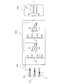
- FIG. 1 shows this system configuration.
- the system includes a traveling battery 220, a boost converter 242, an inverter 240, capacitors 510 and 520, system main relays SMR 500, 504, and 506, a limiting resistor 502, an ECU 600, and a control board 400.
- the inverter 240 includes six IGBTs (Insulated Gate Bipolar Transistors) and six diodes connected in parallel to the respective IGBTs so that a current flows from the emitter side to the collector side of the IGBT.
- Inverter 240 causes motor generator 140 to function as a motor or a generator based on a control signal from control board 400 based on a command from ECU 600, more specifically, a control signal from MG-ECU 700 in control board 400.
- the motor generator 140 functions as a motor
- the inverter 240 turns on / off the gate of each IGBT, converts the DC power supplied from the traveling battery 220 into AC power, and supplies the AC power to the motor generator 140.
- inverter 240 When inverter 240 functions as motor generator, inverter 240 turns on / off the gate of each IGBT to convert AC power generated by motor generator 140 into DC power to charge traveling battery 220.
- the motor generator 140 includes a motor generator 140A and a motor generator 140B.
- the motor generator 140A When the motor generator 140A is for driving, the upper inverter 240 functions as a driving inverter, and when the motor generator 140B is for power generation.
- the lower inverter 240 functions as a power generation inverter.
- Boost converter 242 includes a reactor 311, transistors 312 and 313, and diodes 314 and 315.
- One end of the reactor 311 is connected to the power supply line of the traveling battery 220, and the other end is connected to an intermediate point between the transistor 312 and the transistor 313.
- the transistors 312 and 313 are connected in series between the positive electrode side line and the negative electrode side line of the inverter 240.
- the collector of the transistor 312 is connected to the positive line, and the emitter of the transistor 313 is connected to the negative line.
- diodes 314 and 315 that flow current from the emitter side to the collector side are connected between the collectors and emitters of the transistors 312 and 313.
- boost converter 242 transistors 312 and 313 are turned on / off by control board 400, and the DC voltage supplied from capacitor 510 is boosted and supplied to capacitor 520.
- Capacitor 520 smoothes the DC voltage supplied from boost converter 242 and supplies the smoothed DC power to inverter 240. Since both the capacitors 510 and 520 function as a smoothing capacitor, the capacitors 510 and 520 will be collectively referred to as a smoothing capacitor as appropriate below.
- the positive line before being boosted by the boost converter 242 is referred to as a VL line for convenience
- the positive line after being boosted by the boost converter 242 is referred to as a VH line
- the negative line is referred to as a VN line for convenience.
- ECU 600 controls inverter 240 and SMRs 500, 504, and 506 based on the ignition switch, the amount of depression of the accelerator pedal, the amount of depression of the brake pedal, the detected voltages of the VH and VL lines, and the like.
- Boost converter 242 smoothing capacitors (capacitors 510 and 520), inverter 240, and control board 400 are housed in a case as a power control unit (PCU), and the case is housed in the engine room or below the rear floor.
- the inverter 240 is supplied with electric power obtained by further boosting a high voltage of about several hundred volts from the traveling battery 220 by the boost converter 242.
- the case may be damaged, and high voltage power from the inverter 240 may leak depending on the degree of damage. .
- control board 400 quickly detects an impact caused by the collision, and executes a process of immediately stopping the operation of the high-pressure system.
- the inverter 240 is provided with a rapid discharge circuit including a relay and a discharge resistor Rd between the VH line and the VN line, and the control board 400 instructs the relay of the rapid discharge circuit to be turned on. To discharge the charge accumulated in the smoothing capacitor.
- the collision detection structure of the present embodiment is a case in which an electric device such as an inverter 240 or a smoothing capacitor is accommodated, and a bus bar is protruded from the electrode plate of the smoothing capacitor to face the case.
- the bus bar and the case are brought into contact with each other by deformation of the case, and the occurrence of a collision is detected by detecting a change in the potential of the bus due to the contact.
- the smoothing capacitor includes a positive electrode plate and a negative electrode plate, but the bus bar protrudes from at least one of the positive electrode plate and the negative electrode plate.
- the bus bar potential that is, the smoothing capacitor potential
- the bus bar potential takes a certain value, but when the bus bar contacts the case, the bus bar potential becomes equal to the case potential. Is set to the ground potential, the bus bar potential is also equal to the ground potential. Such a change in the potential of the bus bar detects the contact between the bus bar and the case, and hence the occurrence of a collision.
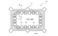
- FIG. 2 shows a plan view of the case 10 that houses the inverter 240 and the smoothing capacitors 510 and 520.
- the case 10 has a flange 11 formed around it, and houses a smoothing capacitor, an inverter 240, smoothing capacitors 510 and 520, and a control board 400 on which the MG-ECU 700 is mounted.
- the case 10 includes two case elements such as an upper case and a lower case or a lid and a main body, and these two case elements are joined to each other via a gasket. Case 10 is connected to the vehicle body earth via a bracket.
- the smoothing capacitors 510 and 520 accommodated in the case 10 occupy a large part of the volume of the case 10.
- the smoothing capacitors 510 and 520 are each composed of a positive electrode plate and a negative electrode plate facing each other, and a dielectric filling between the two electrode plates, but the positive electrode bus bar 12 protrudes from the positive electrode plate and is negative from the negative electrode plate.
- An electrode bus bar 14 is formed to protrude.
- the positive electrode bus bar 12 and the negative electrode bus bar 14 are formed so as to protrude from the entire periphery of the smoothing capacitors 510 and 520, and the negative electrode bus bar 14 exists adjacent to the positive electrode bus bar 12, and is adjacent to the negative electrode bus bar 14.
- the positive electrode bus bar 12 and the negative electrode bus bar 14 are alternately arranged in a plan view so that another positive electrode bus bar 12 is arranged. Both the positive electrode bus bar 12 and the negative electrode bus bar 14 protrude from the smoothing capacitors 510 and 520 to the outside of the capacitor case of the smoothing capacitors 510 and 520 and face the case 10.
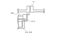
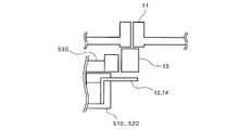
- FIG. 3 is a cross-sectional view taken along the line AA in FIG.
- a positive electrode bus bar 12 and a negative electrode bus bar 14 are formed to protrude from the positive electrode plate and the negative electrode plate of the smoothing capacitors 510 and 520, respectively.
- Both the positive electrode bus bar 12 and the negative electrode bus bar 14 are flat and have a bent shape having a plurality of bent portions, extend to the outside of the capacitor case 530 of the smoothing capacitors 510 and 520, and to the vicinity of the flange 11 of the case 10. Extend.
- the protruding end portions of the positive electrode bus bar 12 and the negative electrode bus bar 14 are bent so as to be substantially parallel to the surface of the flange 11 and face the surface of the flange 11.
- a gap between the flange 11 and the positive electrode bus bar 12 and the negative electrode bus bar 14 is set at an arbitrary interval and insulated.
- the flange 11 and the positive electrode bus bar 12 and the flange 11 and the negative electrode bus bar 14 of the case 10 are not in contact with each other and are in an insulated state.
- the case 10 is deformed by an impact at the time of the collision, and accordingly, the flange 11 is deformed and the flange 11 and the positive electrode bus bar 12 or the flange 11 and the negative electrode bus bar 14 come into contact with each other.
- the configuration of the smoothing capacitors 510 and 520 will be described in more detail. Since the smoothing capacitors 510 and 520 have basically the same shape, the following description will be made taking the smoothing capacitor 520 as an example.
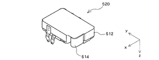
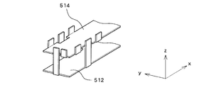
- FIG. 4 and 5 are perspective views seen from the top surface of the smoothing capacitor 520.
- FIG. The smoothing capacitor 520 is composed of a plurality of capacitor elements, and the common positive electrode plate 512 and negative electrode plate 514 of the plurality of capacitor elements are arranged in parallel to the xy plane when the three orthogonal axes are xyz. Is done.
- the positive electrode terminal and the negative electrode terminal 514 extend from the positive electrode plate 512 and the negative electrode plate 514, respectively, but apart from these, the positive electrode bus bar 12 protrudes from the positive electrode plate 512 and the negative electrode bus bar 14 extends from the negative electrode plate 514. Protruding.
- FIG. 6 schematically shows a plan view of the smoothing capacitor 520.
- 7 and 8 are plan views showing only the positive electrode plate 512 and the negative electrode plate 514, respectively.
- a plurality of positive electrode bus bars 12 protrude from the entire periphery of the positive electrode plate 512.
- the planar shape of the positive electrode plate 512 is substantially rectangular, with three positive electrode bus bars 12 protruding at equal intervals on the long side, and two positive electrode bus bars 12 protruding at equal intervals on the short side.
- a plurality of negative electrode bus bars 14 project from the entire periphery of the negative electrode plate 514.
- the planar shape of the negative electrode plate 514 is substantially rectangular, with three positive electrode bus bars 14 projecting at substantially equal intervals on the long side, and two negative electrode bus bars 14 projecting on the short side.
- the formation position of the negative electrode bus bar 14 on the plane is the positive electrode bus bar. It differs from the formation position on 12 planes.
- the formation positions thereof are positioned between the three positive electrode bus bars 12 formed on the long side of the positive electrode plate 512. Is done. The same applies to the two negative electrode bus bars 14 formed on the short side of the negative electrode plate 514.
- the capacitor 4 and 5 show capacitors in which a plurality of capacitor elements are arranged in the xy plane, and the positive electrode plate 512 and the negative electrode plate 514 are arranged in parallel to the xy plane.
- the capacitor 520 is not limited to this, and the same applies to a capacitor in which the positive electrode plate 512 and the negative electrode plate 514 are arranged perpendicular to the xy plane.
- the positive electrode bus bar 12 is formed to protrude from the entire periphery
- the negative electrode bus bar 14 is formed to protrude from the entire periphery.
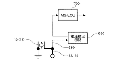
- FIG. 9 shows a basic circuit configuration of the collision detection apparatus according to this embodiment.
- a voltage detection line 630 is connected to the case 10, more specifically, to the positive electrode bus bar 12 and the negative electrode bus bar 14 arranged to extend to the vicinity of the flange 11.
- the voltage detection line 630 an existing voltage detection line for detecting the terminal voltage of the smoothing capacitor 520 can be used as it is. This is one of the advantages of forming the positive electrode bus bar 12 and the negative electrode bus bar 14 as the collision detection means so as to protrude from the positive electrode plate 512 and the negative electrode plate 514, respectively.
- the voltage detection line 630 that also functions as a detection line for detecting the terminal voltage of the smoothing capacitor 520 is connected to the voltage detection circuit 650, and the voltages of the positive electrode bus bar 12 and the negative electrode bus bar 14 are supplied to the voltage detection circuit 650.
- the voltage detection circuit 650 converts the voltages of the positive electrode bus bar 12 and the negative electrode bus bar 14 into a relatively low voltage and outputs the voltage to the MG-ECU 700.
- the MG-ECU 700 determines that at least one of the positive electrode bus bar 12 and the negative electrode bus bar 14 contacts the flange 11 of the case 10 based on the change in the voltage of the positive electrode bus bar 12 and the negative electrode bus bar 14 supplied from the voltage detection circuit 650. Whether or not the vehicle has collided is detected. When detecting a vehicle collision, MG-ECU 700 outputs a command to turn on the discharge circuit including relay and discharge resistor Rd shown in FIG.
- FIG. 10 shows a detailed circuit configuration of the collision detection apparatus according to this embodiment.
- the positive electrode plate of the smoothing capacitor 510 is connected to the VL line (see FIG. 1), and the positive electrode bus bar of the smoothing capacitor 510 is referred to as a positive electrode bus bar 12L correspondingly.
- the positive electrode plate of the smoothing capacitor 520 is connected to the VH line (see FIG. 1), and the positive electrode bus bar of the smoothing capacitor 520 is referred to as the positive electrode bus bar 12H accordingly.
- the negative plates of the smoothing capacitors 510 and 520 are both connected to the negative electrode line VN. Accordingly, the negative electrode bus bars of the smoothing capacitors 510 and 520 are both referred to as the negative electrode bus bar 14.
- the voltages of the positive electrode bus bar 12L and the negative electrode bus bar 14 of the smoothing capacitor 510 and the positive electrode bus bar 12H and the negative electrode bus bar 14 of the smoothing capacitor 520 are supplied to the voltage detection circuit 650 through the voltage detection line 630, respectively.
- the voltage detection circuit 650 is a voltage conversion circuit that converts an input voltage into a relatively low voltage, and includes a high voltage / low voltage conversion circuit that converts the voltage of the positive electrode bus bar 12L and the voltage of the positive electrode bus bar 12H to low voltages. Prepare.
- the high-voltage / low-voltage conversion circuit includes a plurality of voltage dividing resistors and a differential amplifier connected in series with each other.
- the voltage detection line 630 connected to the positive electrode bus bar 12H is connected to one end of the voltage dividing resistors R1, R2, R3, R4 connected in series.
- the voltage detection line 630 connected to the negative electrode bus bar 14 is connected to the other ends of the voltage dividing resistors R1, R2, R3, R4 connected in series.
- connection node between the voltage dividing resistors R1 and R2 is connected to the non-inverting input terminal (+) of the differential amplifier A1, and the connection node between the voltage dividing resistors R3 and R4 is connected to the inverting input terminal ( ⁇ ) of the differential amplifier A1.
- the connection node between the voltage dividing resistors R3 and R4 is set to the ground potential. For example, 5V is supplied as a control voltage to the differential amplifier A1, and the input voltage is converted to a low voltage in the range of the upper limit of 5V and output as VH information.
- the voltage detection line 630 connected to the positive electrode bus bar 12L is connected to one end of the voltage dividing resistors R5, R6, R7, R8 connected in series.
- the voltage detection line 630 connected to the negative electrode bus bar 14 is connected to the other ends of the voltage dividing resistors R5, R6, R7, R8 connected in series with each other.
- the connection node of the voltage dividing resistors R5 and R6 is connected to the non-inverting input terminal (+) of the differential amplifier A2, and the connection node of the voltage dividing resistors R7 and R8 is connected to the inverting input terminal ( ⁇ ) of the differential amplifier A2.
- the connection node between the voltage dividing resistors R6 and R7 is set to the ground potential.
- 5 V is supplied as a control voltage to the differential amplifier A2, and the input voltage is converted to a low voltage within a range of an upper limit of 5 V and output as VL information.
- VH information and VL information from voltage detection circuit 650 are supplied to MG-ECU 700 of control board 400.
- MG-ECU 700 detects the occurrence of a collision based on VH information and VL information. That is, when the voltage is normal, both the VH information and the VL information are in a certain range, for example, 1 V to 4 V. However, when the wire is disconnected due to a collision, both the VH information and the VL information are fixed to the control voltage of 5 V. Detect when it occurs. Further, when both the VH information and the VL information are 0V, it means that the positive electrode bus bars 12H and 12L and the negative electrode bus bar 14 are short-circuited. Therefore, it is detected that a collision has occurred.
- a configuration is added in which two input signals of the differential amplifier circuit A1 and two input signals of the difference image amplifier circuit A2 are supplied to the MG-ECU 700.
- the MG-ECU 700 can directly recognize the voltages of the positive electrode bus bars 12H and 12L and the voltage of the negative electrode bus bar 14 in addition to the VH information and the VL information. Can do. That is, when the voltage of the positive electrode bus bar 12H is 0V and the voltage of the negative electrode bus bar 14 is not 0V, it can be detected that the positive electrode bus bar 12H is in contact with the flange 11 and grounded.
- the positive electrode bus bar 12L when the voltage of the positive electrode bus bar 12L is 0V and the voltage of the negative electrode bus bar 14 is not 0V, it can be detected that the positive electrode bus bar 12L is in contact with the flange 11 and grounded. Further, when the voltages of the positive electrode bus bars 12H and 12L are not 0V and the voltage of the negative electrode bus bar 14 is 0V, it can be detected that the negative electrode bus bar 14 is in contact with the flange 11 and is grounded. In addition, although the case where both the voltage of the positive electrode bus bar 12H and the negative electrode bus bar 14 is 0V is a case where both contacted the flange 11, this is detected as a short circuit.
- FIG. 11 shows a process flowchart for detecting a short circuit between the positive electrode bus bar 12 and the negative electrode bus bar 14 due to a collision.
- the CPU of the MG-ECU 700 acquires the VH information and the VL information, and acquires the rotation speed (Rd) information of the motor generator (MG) 140 (S101).
- the CPU determines whether or not the magnitude (absolute value) of the difference between the previous value and the current value of the acquired VH information exceeds a threshold voltage, for example, 100 V in terms of actual voltage (S102). Similarly, it is determined whether or not the magnitude (absolute value) of the difference between the previous value and the current value of the acquired VL information exceeds the threshold voltage.
- a threshold voltage for example, 100 V in terms of actual voltage (S102).
- the CPU determines whether or not the magnitude (absolute value) of the difference between the previous value and the current value of the acquired VL information exceeds the threshold voltage.
- the CPU next determines whether or not the difference value of the rotational speed Rd exceeds a threshold, for example, 200 rpm. Determine (S103). This determination is a process for determining whether or not sudden braking is applied. When sudden braking is applied, the rotational speed Rd decreases rapidly, so the difference value exceeds the threshold value and is determined as YES.
- a threshold for example, 200 rpm.
- the CPU regards that sudden braking has been applied due to a collision (S104). Then, it detects that a PN short circuit has occurred due to a collision (S105), outputs a command to turn on a rapid discharge circuit comprising a relay and a discharge resistor, and rapidly discharges the smoothing capacitors 510 and 520 (S106).
- collision detection is performed when the difference value of VH information or the difference value of VL information exceeds the threshold voltage, but both the difference value of VH information and the difference value of VL information exceed the threshold voltage. In some cases, a collision may be detected.
- collision detection is performed when the difference value of VH information or the difference value of VL information exceeds a threshold voltage, but collision detection is performed when the difference value of VH information and VL information is approximately zero. May be.
- FIG. 12 shows a processing flowchart for detecting both a short circuit and a ground fault on the positive electrode side and the negative electrode side due to a collision.
- the CPU of the NG-ECU 700 acquires the VH and VL information and the rotation speed (Rd) information of the motor generator 140 (S201).
- the difference value of the rotational speed Rd is further set to a threshold value, for example, 200 rpm. It is determined whether or not (S211). When the difference value of the rotational speed exceeds the threshold value, it is considered that sudden braking has been applied due to the collision (S212), and it is detected that a P or N ground fault has occurred due to the collision (S213). A command to turn on the rapid discharge circuit is output to discharge the smoothing capacitors 510 and 520 (S206).
- the PN short circuit may be determined based on the fact that the difference between the VH information and the VL information is substantially zero.
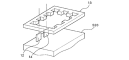
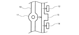
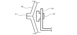
- FIGS. 13 and 14 are plan views of the case 10 according to another embodiment. 14 is a cross-sectional view taken along the line BB in FIG.
- the metal frame 13 is disposed around the smoothing capacitors 510 and 520 so as to surround them.
- the positive electrode bus bar 12 and the negative electrode bus bar 14 are formed to protrude from the positive and negative plates of the smoothing capacitors 510 and 520 and extend to the vicinity of the flange 11 of the case 10.
- a metal frame 13 is disposed between the bus bar 12 and the end of the negative electrode bus bar 14.
- FIG. 15 and 16 show other configurations of the positive electrode plate 512 and the negative electrode plate 514 of the smoothing capacitor 520.
- FIG. 15 the positive electrode plate 512 and the negative electrode plate 514 are disposed substantially perpendicular to the xy plane, and the positive electrode bus bar 12 protrudes from the end of the positive electrode plate 512.
- the positive electrode bus bar 12 extends in the y direction from the positive electrode plate 512 toward the negative electrode plate 514, and is further bent in the z direction so that an end portion exists on the same plane as the negative electrode plate 514.
- negative electrode bus bars 14 are formed on the negative electrode plate 514 so as to protrude in the z direction at equal intervals.
- the positive electrode bus bar 12 is disposed between the negative electrode bus bars 14. In FIG.
- the positive electrode plate 512 and the negative electrode plate 514 are disposed substantially parallel to the xy plane, and the positive electrode bus bar 12 is formed to protrude from the end of the positive electrode plate 512.
- the positive electrode bus bar 12 extends in the z direction from the positive electrode plate 512 toward the negative electrode plate 514.
- negative electrode bus bars 14 are formed on the negative electrode plate 514 so as to protrude in the z direction at equal intervals.
- the positive electrode bus bar 12 is disposed between the negative electrode bus bars 14.
- the metal frame 13 is disposed so as to surround the smoothing capacitors 510 and 520, as shown in FIG. 17, irregularities are formed on the inner surface side of the metal frame 13, and the positive electrode bus bar 12, The negative electrode bus bar 14 may be inserted.
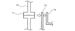
- FIG. 18 and 19 show the relationship between the metal frame 13, the positive electrode bus bar 12, and the negative electrode bus bar 14 at the time of collision in the configuration of FIG. 18 is a plan view, and FIG. 19 is a side view.
- Concavities and convexities are formed on the inner surface of the metal frame 13, and the positive electrode bus bars 12 and the negative electrode bus bars 14 are alternately inserted into adjacent concave portions.
- the flange 11 of the case 10 and the metal frame 13 are separated from each other, and the metal frame 13 and the positive electrode bus bar 12 and the metal frame 13 and the negative electrode bus bar 14 are also separated from each other.
- the flange 11 When a collision occurs, the flange 11 is deformed and moved by an impact at the time of the collision, and the flange 11 and the metal frame 13 come into contact with each other. Further, the metal frame 13 is deformed / moved to come into contact with the positive electrode bus bar 12 or the negative electrode bus bar 14. When the metal frame 13 contacts the positive electrode bus bar 12 and the negative electrode bus bar 14, a PN short circuit occurs. Further, when the metal frame 13 contacts the positive electrode bus bar 12 or the negative electrode bus bar 14, a P or N ground fault occurs.
- the positive electrode bus bar 12 and the negative electrode bus bar 14 are arranged in a direction substantially parallel to the inner surface of the case 10, and the distance from the case 10 is set to be the positive electrode bus bar 12 and the negative electrode bus bar 14.
- the positive electrode bus bar 12 may be arranged between the case 10 and the negative electrode bus bar 14. That is, the positive electrode bus bar 12 and the negative electrode bus bar 14 may be arranged in a direction substantially perpendicular to the inner surface of the case 10. In this case, when a collision occurs, the flange 11 of the case 10 is deformed / moved to come into contact with the positive electrode bus bar 12, and the positive electrode bus bar 12 comes into contact with the negative electrode bus bar 14.
- FIG. 22 and the side view of FIG. 23 are similarly configured such that the positive electrode bus bar 12 is disposed between the case 10 and the negative electrode bus bar 14, but facing the negative electrode bus bar 14 of the positive electrode bus bar 12.
- a convex portion is formed on the surface to be touched, and the positive electrode bus bar 12 and the negative electrode bus bar 14 are easily contacted by an impact at the time of collision.
- the positive electrode bus bar 12 and the negative electrode bus bar 14 are formed to protrude from the periphery of the smoothing capacitors 512 and 514 from the positive electrode plate 512 of the smoothing capacitors 510 and 520, but from the positive electrode plate 512.
- the collision may be detected by projecting only the positive electrode bus bar 12 and detecting only the ground fault of the positive electrode bus bar 12.
- the collision may be detected by forming only the negative electrode bus bar 14 to protrude from the negative electrode plate 514 and detecting only the ground fault of the negative electrode bus bar 14.
Landscapes
- Engineering & Computer Science (AREA)
- Transportation (AREA)
- Mechanical Engineering (AREA)
- Power Engineering (AREA)
- Sustainable Energy (AREA)
- Sustainable Development (AREA)
- Life Sciences & Earth Sciences (AREA)
- Physics & Mathematics (AREA)
- General Physics & Mathematics (AREA)
- Health & Medical Sciences (AREA)
- Biomedical Technology (AREA)
- General Health & Medical Sciences (AREA)
- Automation & Control Theory (AREA)
- Electric Propulsion And Braking For Vehicles (AREA)
Abstract
Description
まず、システムの全体構成について説明する。システムの全体構成は、特許文献1に記載されたシステム構成と基本的に同様である。図1に、このシステム構成を示す。
本実施形態の衝突検知構造は、インバータ240や平滑コンデンサ等の電気機器を収容するケースにおいて、平滑コンデンサの極板からバスバを突出させてケースに対向させ、衝突時の衝撃によるケースの変形によりバスバとケースとを接触させ、この接触によるバスパの電位変化を検出することで衝突の発生を検出するものである。平滑コンデンサは正極板及び負極板から構成されるが、バスバは正極板あるいは負極板の少なくともいずれかから突出させる。平常時には平滑コンデンサのバスバとケースとは絶縁されているためバスバの電位、すなわち平滑コンデンサの電位はある値をとるが、バスバがケースに接触すると、バスバの電位はケースの電位と等しくなり、ケースがアース電位に設定されている場合にはバスバの電位もアース電位に等しくなる。このようなバスバの電位変化により、バスバとケースとの接触、ひいては衝突の発生を検知する。
図13及び図14に、他の実施形態におけるケース10の平面図を示す。図14は、図13におけるB-B断面図である。本実施形態では、平滑コンデンサ510,520を囲むようにその周囲に金属枠13が配置される。図14に示すように、正電極バスバ12、負電極バスバ14は平滑コンデンサ510,520の正極板、負極板から突出形成されてケース10のフランジ11近傍まで延在するが、フランジ11と正電極バスバ12、負電極バスバ14の端部との間に金属枠13が配置される。
Claims (11)
- 車両用衝突検知装置であって、
コンデンサと、
前記コンデンサを収容するケースと、
前記コンデンサの極板に接続され、前記コンデンサの周囲から突出してケースの内面に対向する電極バスバと、
前記電極バスバの電圧変化を検出することで衝突を検知する制御部と、
を備えることを特徴とする車両用衝突検知装置。 - 請求項1記載の車両用衝突検知装置において、
前記電極バスバは、前記コンデンサの正極板あるいは負極板の少なくともいずれかに接続されることを特徴とする車両用衝突検知装置。 - 請求項1記載の車両用衝突検知装置において、さらに、
前記ケースに収容されるとともに前記コンデンサの周囲を囲む金属枠と、
を備え、前記電極バスバは、前記金属枠を挟んで前記ケースの内面に対向する
ことを特徴とする車両用衝突検知装置。 - 請求項1記載の車両用衝突検知装置において、
前記電極バスバは、前記ケースに形成されるフランジと同一面上において前記ケースの内面に対向する
ことを特徴とする車両用衝突検知装置。 - 請求項1記載の車両用衝突検知装置において、
前記コンデンサの端子電圧を前記制御部に供給する電圧検出線
を備え、前記電圧検出線が前記電極バスバの電圧を前記制御部に供給することを特徴とする車両用衝突検知装置。 - 請求項1記載の車両用衝突検知装置において、
前記電極バスバは、前記コンデンサの正極板及び負極板に接続され、
前記制御部は、前記正極板に接続される電極バスバと前記負極板に接続される電極バスバとの短絡による電圧変化を検出することで衝突を検知する
ことを特徴とする車両用衝突検知装置。 - 請求項1記載の車両用衝突検知装置において、
前記電極バスバは、前記コンデンサの正極板あるいは負極板のいずれかに接続され、
前記制御部は、前記正極板に接続される電極バスバあるいは前記負極板に接続される電極バスバの地絡による電圧変化を検出することで衝突を検知する
ことを特徴とする車両用衝突検知装置。 - 請求項1記載の車両用衝突検知装置において、
前記電極バスバは、前記コンデンサの正極板及び負極板に接続され、
前記正極板に接続される電極バスバ及び前記負極板に接続される電極バスバは、前記ケースの内面に対して互いに略平行な方向に配列することを特徴とする車両用衝突検知装置。 - 請求項1記載の車両用衝突検知装置において、
前記電極バスバは、前記コンデンサの正極板及び負極板に接続され、
前記正極板に接続される電極バスバ及び前記負極板に接続される電極バスバは、前記ケースの内面に対して互いに略垂直な方向に配列することを特徴とする車両用衝突検知装置。 - 請求項3記載の車両用衝突検知装置において、
前記電極バスバは、前記コンデンサの正極板及び負極板に接続され、
前記制御部は、前記正極板に接続される電極バスバ及び前記負極板に接続される電極バスバと前記金属枠との接触による電圧変化を検出することで衝突を検知する
ことを特徴とする車両用衝突検知装置。 - 請求項3記載の車両用衝突検知装置において、
前記電極バスバは、前記コンデンサの正極板あるいは負極板のいずれかに接続され、
前記制御部は、前記正極板に接続される電極バスバあるいは前記負極板に接続される電極バスバと前記金属枠との接触による電圧変化を検出することで衝突を検知する
ことを特徴とする車両用衝突検知装置。
Priority Applications (5)
| Application Number | Priority Date | Filing Date | Title |
|---|---|---|---|
| CN201180070690.2A CN103502059B (zh) | 2011-05-12 | 2011-05-12 | 车辆用碰撞检测装置 |
| JP2013513865A JP5590231B2 (ja) | 2011-05-12 | 2011-05-12 | 車両用衝突検知装置 |
| PCT/JP2011/060948 WO2012153417A1 (ja) | 2011-05-12 | 2011-05-12 | 車両用衝突検知装置 |
| DE112011105237.5T DE112011105237B4 (de) | 2011-05-12 | 2011-05-12 | Fahrzeug-Kollisionserfassungsvorrichtung |
| US14/115,520 US9075096B2 (en) | 2011-05-12 | 2011-05-12 | Collision detection device for vehicle |
Applications Claiming Priority (1)
| Application Number | Priority Date | Filing Date | Title |
|---|---|---|---|
| PCT/JP2011/060948 WO2012153417A1 (ja) | 2011-05-12 | 2011-05-12 | 車両用衝突検知装置 |
Publications (1)
| Publication Number | Publication Date |
|---|---|
| WO2012153417A1 true WO2012153417A1 (ja) | 2012-11-15 |
Family
ID=47138915
Family Applications (1)
| Application Number | Title | Priority Date | Filing Date |
|---|---|---|---|
| PCT/JP2011/060948 Ceased WO2012153417A1 (ja) | 2011-05-12 | 2011-05-12 | 車両用衝突検知装置 |
Country Status (5)
| Country | Link |
|---|---|
| US (1) | US9075096B2 (ja) |
| JP (1) | JP5590231B2 (ja) |
| CN (1) | CN103502059B (ja) |
| DE (1) | DE112011105237B4 (ja) |
| WO (1) | WO2012153417A1 (ja) |
Cited By (4)
| Publication number | Priority date | Publication date | Assignee | Title |
|---|---|---|---|---|
| CN103926450A (zh) * | 2014-04-25 | 2014-07-16 | 华为技术有限公司 | 母排电压检测方法和电路 |
| CN104880245A (zh) * | 2015-02-12 | 2015-09-02 | 无锡市崇安区科技创业服务中心 | 一种基于车辆碰撞噪声特征的车祸定位报警系统 |
| KR20160061114A (ko) * | 2014-11-21 | 2016-05-31 | 현대자동차주식회사 | 에어백 구동 장치 |
| JP2021019427A (ja) * | 2019-07-19 | 2021-02-15 | アイシン・エィ・ダブリュ株式会社 | インバータ装置 |
Families Citing this family (6)
| Publication number | Priority date | Publication date | Assignee | Title |
|---|---|---|---|---|
| CN104807538A (zh) * | 2015-02-12 | 2015-07-29 | 无锡市崇安区科技创业服务中心 | 一种车辆碰撞噪声特征检测系统 |
| GB2539659B (en) * | 2015-06-22 | 2019-05-01 | Octo Telematics Spa | Collision Diagnosis for a Traffic Event |
| US10541622B2 (en) * | 2016-06-15 | 2020-01-21 | Mitsubishi Electric Corporation | Electric motor drive device |
| JP6711312B2 (ja) * | 2017-05-12 | 2020-06-17 | 株式会社デンソー | 車両の自動運転制御システム |
| EP3810454A1 (en) * | 2018-06-21 | 2021-04-28 | Jaguar Land Rover Limited | Discharging a bus of an electrically powered or hybrid vehicle |
| DE102018221331A1 (de) * | 2018-12-10 | 2020-06-10 | Audi Ag | Vorrichtung und Verfahren zum Detektieren einer potentiellen mechanischen Beschädigung eines Fahrzeugbauteils eines Kraftfahrzeugs |
Citations (8)
| Publication number | Priority date | Publication date | Assignee | Title |
|---|---|---|---|---|
| JPH06213924A (ja) * | 1993-01-13 | 1994-08-05 | Hitachi Ltd | トランスジューサ、これを利用したマイクロセンサ、車両制御システム |
| JP2007155700A (ja) * | 2005-11-09 | 2007-06-21 | Denso Corp | 車両用衝突検知装置 |
| JP2007526841A (ja) * | 2004-04-02 | 2007-09-20 | ローベルト ボツシユ ゲゼルシヤフト ミツト ベシユレンクテル ハフツング | マルチファンクションアップフロントセンサ |
| JP2007292593A (ja) * | 2006-04-25 | 2007-11-08 | Denso Corp | 衝突検出装置 |
| JP2008154315A (ja) * | 2006-12-14 | 2008-07-03 | Toyota Motor Corp | 車両の制御装置 |
| JP2008207629A (ja) * | 2007-02-23 | 2008-09-11 | Nippon Soken Inc | 衝突検出装置 |
| JP2009143518A (ja) * | 2007-11-22 | 2009-07-02 | Denso Corp | 車両用側突検出装置及びそれを利用した車両用乗員保護システム |
| JP2010071858A (ja) * | 2008-09-19 | 2010-04-02 | Denso Corp | センサ信号処理装置 |
Family Cites Families (12)
| Publication number | Priority date | Publication date | Assignee | Title |
|---|---|---|---|---|
| DE4242230A1 (de) * | 1992-12-15 | 1994-06-16 | Diehl Gmbh & Co | Sensoreinrichtung zum Erkennen eines seitlichen Aufpralles auf ein Kraftfahrzeug |
| DE10018806A1 (de) * | 2000-04-15 | 2001-10-25 | Volkswagen Ag | Vorrichtung zur kapazitiven Messung einer Verformung eines Bauteils, insbesondere eines Bauteils eines Kraftfahrzeugs |
| JP2004361388A (ja) * | 2003-05-15 | 2004-12-24 | Mitsubishi Electric Corp | 容量型慣性力検出装置 |
| US7284432B2 (en) * | 2005-03-29 | 2007-10-23 | Agency For Science, Technology & Research | Acceleration sensitive switch |
| JP5042475B2 (ja) * | 2005-07-27 | 2012-10-03 | タカタ株式会社 | 変位情報導出装置、乗員拘束システム、車両、変位情報導出方法 |
| JP2008216118A (ja) * | 2007-03-06 | 2008-09-18 | Denso Corp | 力学量センサ |
| US8140218B2 (en) | 2007-11-07 | 2012-03-20 | Denso Corporation | Detection device for side collision of vehicle and passenger protection system having the same |
| JP5120240B2 (ja) | 2008-12-22 | 2013-01-16 | 株式会社豊田自動織機 | 電動コンプレッサ |
| JP5298907B2 (ja) | 2009-02-09 | 2013-09-25 | トヨタ自動車株式会社 | 放電機構 |
| JP2010200455A (ja) * | 2009-02-24 | 2010-09-09 | Toyota Motor Corp | 自動車および平滑コンデンサの放電方法 |
| JP2011128132A (ja) * | 2009-11-19 | 2011-06-30 | Seiko Epson Corp | 物理量センサー、物理量センサーの製造方法、および電子機器 |
| WO2012143987A1 (ja) | 2011-04-18 | 2012-10-26 | トヨタ自動車株式会社 | 車両用衝突検知装置 |
-
2011
- 2011-05-12 JP JP2013513865A patent/JP5590231B2/ja active Active
- 2011-05-12 CN CN201180070690.2A patent/CN103502059B/zh active Active
- 2011-05-12 US US14/115,520 patent/US9075096B2/en active Active
- 2011-05-12 DE DE112011105237.5T patent/DE112011105237B4/de active Active
- 2011-05-12 WO PCT/JP2011/060948 patent/WO2012153417A1/ja not_active Ceased
Patent Citations (8)
| Publication number | Priority date | Publication date | Assignee | Title |
|---|---|---|---|---|
| JPH06213924A (ja) * | 1993-01-13 | 1994-08-05 | Hitachi Ltd | トランスジューサ、これを利用したマイクロセンサ、車両制御システム |
| JP2007526841A (ja) * | 2004-04-02 | 2007-09-20 | ローベルト ボツシユ ゲゼルシヤフト ミツト ベシユレンクテル ハフツング | マルチファンクションアップフロントセンサ |
| JP2007155700A (ja) * | 2005-11-09 | 2007-06-21 | Denso Corp | 車両用衝突検知装置 |
| JP2007292593A (ja) * | 2006-04-25 | 2007-11-08 | Denso Corp | 衝突検出装置 |
| JP2008154315A (ja) * | 2006-12-14 | 2008-07-03 | Toyota Motor Corp | 車両の制御装置 |
| JP2008207629A (ja) * | 2007-02-23 | 2008-09-11 | Nippon Soken Inc | 衝突検出装置 |
| JP2009143518A (ja) * | 2007-11-22 | 2009-07-02 | Denso Corp | 車両用側突検出装置及びそれを利用した車両用乗員保護システム |
| JP2010071858A (ja) * | 2008-09-19 | 2010-04-02 | Denso Corp | センサ信号処理装置 |
Cited By (6)
| Publication number | Priority date | Publication date | Assignee | Title |
|---|---|---|---|---|
| CN103926450A (zh) * | 2014-04-25 | 2014-07-16 | 华为技术有限公司 | 母排电压检测方法和电路 |
| KR20160061114A (ko) * | 2014-11-21 | 2016-05-31 | 현대자동차주식회사 | 에어백 구동 장치 |
| KR101655573B1 (ko) * | 2014-11-21 | 2016-09-07 | 현대자동차주식회사 | 에어백 구동 장치 |
| CN104880245A (zh) * | 2015-02-12 | 2015-09-02 | 无锡市崇安区科技创业服务中心 | 一种基于车辆碰撞噪声特征的车祸定位报警系统 |
| JP2021019427A (ja) * | 2019-07-19 | 2021-02-15 | アイシン・エィ・ダブリュ株式会社 | インバータ装置 |
| JP7363151B2 (ja) | 2019-07-19 | 2023-10-18 | 株式会社アイシン | インバータ装置 |
Also Published As
| Publication number | Publication date |
|---|---|
| DE112011105237T5 (de) | 2014-02-13 |
| JP5590231B2 (ja) | 2014-09-17 |
| CN103502059A (zh) | 2014-01-08 |
| US9075096B2 (en) | 2015-07-07 |
| US20140077826A1 (en) | 2014-03-20 |
| CN103502059B (zh) | 2015-07-01 |
| DE112011105237B4 (de) | 2015-06-18 |
| JPWO2012153417A1 (ja) | 2014-07-28 |
Similar Documents
| Publication | Publication Date | Title |
|---|---|---|
| JP5590231B2 (ja) | 車両用衝突検知装置 | |
| JP5365705B2 (ja) | 車両用衝突検知装置 | |
| JP5629671B2 (ja) | 電源装置 | |
| JP5808678B2 (ja) | 電動車両 | |
| WO2007142173A1 (ja) | 車載用電子装置およびそれを搭載する車両 | |
| KR101714243B1 (ko) | 친환경 차량의 전류센서 진단 장치 및 그 방법 | |
| US9258934B2 (en) | In-vehicle electronic device and vehicle having the electronic device | |
| JP5508639B2 (ja) | 車両用の電源制御装置 | |
| KR101841053B1 (ko) | 실드 전선 및 통신 시스템 | |
| JP7135515B2 (ja) | 電力変換装置 | |
| CN104105974A (zh) | 车载电源装置 | |
| JP5699693B2 (ja) | 車両用衝突検知装置 | |
| JP6693323B2 (ja) | 電気自動車用の電源システム | |
| JP2012154860A (ja) | 車載電気機器の破損検知装置 | |
| JP2021112045A (ja) | 電力分配装置 | |
| CN108749579B (zh) | 一种高压系统的接地自检方法、装置、高压系统及汽车 | |
| JP2000102288A (ja) | インバータ装置 | |
| US20240027502A1 (en) | Current detection device, current sensor, and electric power conversion device | |
| JP6668851B2 (ja) | 電動車両の電力変換装置 | |
| JP2018102030A (ja) | 電気回路装置 | |
| JP6477787B2 (ja) | 通信システム | |
| JP2013027086A (ja) | 駆動用モータを備える自動車 | |
| CN120153547A (zh) | 电源装置 | |
| JP2021066189A (ja) | 電力変換器の車載構造 |
Legal Events
| Date | Code | Title | Description |
|---|---|---|---|
| 121 | Ep: the epo has been informed by wipo that ep was designated in this application |
Ref document number: 11865239 Country of ref document: EP Kind code of ref document: A1 |
|
| ENP | Entry into the national phase |
Ref document number: 2013513865 Country of ref document: JP Kind code of ref document: A |
|
| WWE | Wipo information: entry into national phase |
Ref document number: 14115520 Country of ref document: US |
|
| WWE | Wipo information: entry into national phase |
Ref document number: 1120111052375 Country of ref document: DE Ref document number: 112011105237 Country of ref document: DE |
|
| 122 | Ep: pct application non-entry in european phase |
Ref document number: 11865239 Country of ref document: EP Kind code of ref document: A1 |