WO2012147923A1 - 切削インサートおよび切削工具、並びにそれを用いた切削加工物の製造方法 - Google Patents
切削インサートおよび切削工具、並びにそれを用いた切削加工物の製造方法 Download PDFInfo
- Publication number
- WO2012147923A1 WO2012147923A1 PCT/JP2012/061389 JP2012061389W WO2012147923A1 WO 2012147923 A1 WO2012147923 A1 WO 2012147923A1 JP 2012061389 W JP2012061389 W JP 2012061389W WO 2012147923 A1 WO2012147923 A1 WO 2012147923A1
- Authority
- WO
- WIPO (PCT)
- Prior art keywords
- cutting edge
- cutting
- main
- corner
- sub
- Prior art date
Links
Images


Classifications
-
- B—PERFORMING OPERATIONS; TRANSPORTING
- B23—MACHINE TOOLS; METAL-WORKING NOT OTHERWISE PROVIDED FOR
- B23C—MILLING
- B23C5/00—Milling-cutters
- B23C5/16—Milling-cutters characterised by physical features other than shape
- B23C5/20—Milling-cutters characterised by physical features other than shape with removable cutter bits or teeth or cutting inserts
-
- B—PERFORMING OPERATIONS; TRANSPORTING
- B23—MACHINE TOOLS; METAL-WORKING NOT OTHERWISE PROVIDED FOR
- B23C—MILLING
- B23C5/00—Milling-cutters
- B23C5/02—Milling-cutters characterised by the shape of the cutter
- B23C5/06—Face-milling cutters, i.e. having only or primarily a substantially flat cutting surface
-
- B—PERFORMING OPERATIONS; TRANSPORTING
- B23—MACHINE TOOLS; METAL-WORKING NOT OTHERWISE PROVIDED FOR
- B23B—TURNING; BORING
- B23B27/00—Tools for turning or boring machines; Tools of a similar kind in general; Accessories therefor
- B23B27/14—Cutting tools of which the bits or tips or cutting inserts are of special material
- B23B27/18—Cutting tools of which the bits or tips or cutting inserts are of special material with cutting bits or tips or cutting inserts rigidly mounted, e.g. by brazing
-
- B—PERFORMING OPERATIONS; TRANSPORTING
- B23—MACHINE TOOLS; METAL-WORKING NOT OTHERWISE PROVIDED FOR
- B23C—MILLING
- B23C5/00—Milling-cutters
- B23C5/16—Milling-cutters characterised by physical features other than shape
- B23C5/20—Milling-cutters characterised by physical features other than shape with removable cutter bits or teeth or cutting inserts
- B23C5/202—Plate-like cutting inserts with special form
-
- B—PERFORMING OPERATIONS; TRANSPORTING
- B23—MACHINE TOOLS; METAL-WORKING NOT OTHERWISE PROVIDED FOR
- B23C—MILLING
- B23C5/00—Milling-cutters
- B23C5/16—Milling-cutters characterised by physical features other than shape
- B23C5/20—Milling-cutters characterised by physical features other than shape with removable cutter bits or teeth or cutting inserts
- B23C5/22—Securing arrangements for bits or teeth or cutting inserts
- B23C5/2204—Securing arrangements for bits or teeth or cutting inserts with cutting inserts clamped against the walls of the recess in the cutter body by a clamping member acting upon the wall of a hole in the insert
-
- B—PERFORMING OPERATIONS; TRANSPORTING
- B23—MACHINE TOOLS; METAL-WORKING NOT OTHERWISE PROVIDED FOR
- B23C—MILLING
- B23C2200/00—Details of milling cutting inserts
- B23C2200/04—Overall shape
- B23C2200/0405—Hexagonal
-
- B—PERFORMING OPERATIONS; TRANSPORTING
- B23—MACHINE TOOLS; METAL-WORKING NOT OTHERWISE PROVIDED FOR
- B23C—MILLING
- B23C2200/00—Details of milling cutting inserts
- B23C2200/04—Overall shape
- B23C2200/0405—Hexagonal
- B23C2200/0411—Hexagonal irregular
-
- B—PERFORMING OPERATIONS; TRANSPORTING
- B23—MACHINE TOOLS; METAL-WORKING NOT OTHERWISE PROVIDED FOR
- B23C—MILLING
- B23C2200/00—Details of milling cutting inserts
- B23C2200/08—Rake or top surfaces
- B23C2200/085—Rake or top surfaces discontinuous
-
- B—PERFORMING OPERATIONS; TRANSPORTING
- B23—MACHINE TOOLS; METAL-WORKING NOT OTHERWISE PROVIDED FOR
- B23C—MILLING
- B23C2200/00—Details of milling cutting inserts
- B23C2200/20—Top or side views of the cutting edge
- B23C2200/205—Discontinuous cutting edges
-
- B—PERFORMING OPERATIONS; TRANSPORTING
- B23—MACHINE TOOLS; METAL-WORKING NOT OTHERWISE PROVIDED FOR
- B23C—MILLING
- B23C2200/00—Details of milling cutting inserts
- B23C2200/20—Top or side views of the cutting edge
- B23C2200/208—Wiper, i.e. an auxiliary cutting edge to improve surface finish
-
- B—PERFORMING OPERATIONS; TRANSPORTING
- B23—MACHINE TOOLS; METAL-WORKING NOT OTHERWISE PROVIDED FOR
- B23C—MILLING
- B23C2210/00—Details of milling cutters
- B23C2210/04—Angles
- B23C2210/0407—Cutting angles
- B23C2210/0414—Cutting angles different
-
- B—PERFORMING OPERATIONS; TRANSPORTING
- B23—MACHINE TOOLS; METAL-WORKING NOT OTHERWISE PROVIDED FOR
- B23C—MILLING
- B23C2210/00—Details of milling cutters
- B23C2210/04—Angles
- B23C2210/0407—Cutting angles
- B23C2210/0421—Cutting angles negative
- B23C2210/0428—Cutting angles negative axial rake angle
-
- B—PERFORMING OPERATIONS; TRANSPORTING
- B23—MACHINE TOOLS; METAL-WORKING NOT OTHERWISE PROVIDED FOR
- B23C—MILLING
- B23C2210/00—Details of milling cutters
- B23C2210/04—Angles
- B23C2210/0407—Cutting angles
- B23C2210/0442—Cutting angles positive
- B23C2210/045—Cutting angles positive axial rake angle
-
- B—PERFORMING OPERATIONS; TRANSPORTING
- B23—MACHINE TOOLS; METAL-WORKING NOT OTHERWISE PROVIDED FOR
- B23C—MILLING
- B23C2210/00—Details of milling cutters
- B23C2210/04—Angles
- B23C2210/0407—Cutting angles
- B23C2210/0442—Cutting angles positive
- B23C2210/0457—Cutting angles positive radial rake angle
-
- B—PERFORMING OPERATIONS; TRANSPORTING
- B23—MACHINE TOOLS; METAL-WORKING NOT OTHERWISE PROVIDED FOR
- B23C—MILLING
- B23C2210/00—Details of milling cutters
- B23C2210/66—Markings, i.e. symbols or indicating marks
-
- B—PERFORMING OPERATIONS; TRANSPORTING
- B23—MACHINE TOOLS; METAL-WORKING NOT OTHERWISE PROVIDED FOR
- B23C—MILLING
- B23C2220/00—Details of milling processes
- B23C2220/56—Plunge milling
-
- Y—GENERAL TAGGING OF NEW TECHNOLOGICAL DEVELOPMENTS; GENERAL TAGGING OF CROSS-SECTIONAL TECHNOLOGIES SPANNING OVER SEVERAL SECTIONS OF THE IPC; TECHNICAL SUBJECTS COVERED BY FORMER USPC CROSS-REFERENCE ART COLLECTIONS [XRACs] AND DIGESTS
- Y10—TECHNICAL SUBJECTS COVERED BY FORMER USPC
- Y10T—TECHNICAL SUBJECTS COVERED BY FORMER US CLASSIFICATION
- Y10T407/00—Cutters, for shaping
- Y10T407/22—Cutters, for shaping including holder having seat for inserted tool
- Y10T407/2268—Cutters, for shaping including holder having seat for inserted tool with chip breaker, guide or deflector
-
- Y—GENERAL TAGGING OF NEW TECHNOLOGICAL DEVELOPMENTS; GENERAL TAGGING OF CROSS-SECTIONAL TECHNOLOGIES SPANNING OVER SEVERAL SECTIONS OF THE IPC; TECHNICAL SUBJECTS COVERED BY FORMER USPC CROSS-REFERENCE ART COLLECTIONS [XRACs] AND DIGESTS
- Y10—TECHNICAL SUBJECTS COVERED BY FORMER USPC
- Y10T—TECHNICAL SUBJECTS COVERED BY FORMER US CLASSIFICATION
- Y10T407/00—Cutters, for shaping
- Y10T407/23—Cutters, for shaping including tool having plural alternatively usable cutting edges
- Y10T407/235—Cutters, for shaping including tool having plural alternatively usable cutting edges with integral chip breaker, guide or deflector
-
- Y—GENERAL TAGGING OF NEW TECHNOLOGICAL DEVELOPMENTS; GENERAL TAGGING OF CROSS-SECTIONAL TECHNOLOGIES SPANNING OVER SEVERAL SECTIONS OF THE IPC; TECHNICAL SUBJECTS COVERED BY FORMER USPC CROSS-REFERENCE ART COLLECTIONS [XRACs] AND DIGESTS
- Y10—TECHNICAL SUBJECTS COVERED BY FORMER USPC
- Y10T—TECHNICAL SUBJECTS COVERED BY FORMER US CLASSIFICATION
- Y10T83/00—Cutting
- Y10T83/04—Processes
Definitions
- the present invention relates to a cutting insert, a cutting tool, and a manufacturing method of a cut product using the cutting insert.
- One of the problems of the present invention is to provide a cutting insert and a cutting tool having both a low cutting resistance and an excellent fracture resistance, and a method for producing a cut product using the cutting insert.
- a cutting insert includes a polygonal upper surface, a lower surface having the same shape as the upper surface, a side surface connected to each of the upper surface and the lower surface, and a line of intersection between the upper surface and the side surface.
- An upper cutting edge located at a portion, and the upper surface alternately includes three main corners having a first inner angle and three sub-corners having a second inner angle larger than the first inner angle.
- the upper cutting edge includes a first sub-corner and a second sub-corner that are adjacent to the first main corner of the three sub-corners from the first main corner of the three main corners.
- the minor cut It has a main cutting edge which is inclined at a second inclination angle greater than the first inclination angle toward the lower surface with respect to the said vertical plane with increasing distance from.
- the cutting tool which concerns on embodiment of this invention is equipped with the cutting insert which concerns on embodiment mentioned above, and the holder to which the said cutting insert is attached,
- the said cutting insert is a said 1st main corner among the said upper cutting blades.
- the axial rake angle of the first main cutting section across the adjacent first sub-corner is positive, and the non-cut across the second main corner adjacent to the first sub-corner among the upper cutting edges.
- the axial rake angle of the cutting part is negative.
- the manufacturing method of the cut workpiece which concerns on embodiment of this invention is a process which rotates the cutting tool which concerns on embodiment mentioned above on the basis of the rotating shaft of the said holder, The said upper cutting blade of the said cutting tool which is rotating A step of contacting the surface of the work material, and a step of separating the cutting tool from the work material.
- the upper surface has alternately three main corners provided with the 1st interior angle, and 3 sub corners provided with the 2nd interior angle larger than the 1st interior angle.
- each of the three main corners can be cut in both right-handed and left-handed Can be used.
- the upper cutting edge is directed from the first main corner of the three main corners to each of the first sub-corner and the second sub-corner adjacent to the first main corner of the three sub-corners.
- the secondary cutting edge inclined at the first inclination angle toward the lower surface with reference to a vertical plane perpendicular to the central axis passing through the upper and lower surfaces as the distance from the corner cutting edge, and the secondary cutting edge
- the main cutting edge which inclines with the 2nd inclination angle larger than a 1st inclination angle toward a lower surface on the basis of a perpendicular plane as it leaves
- the upper cutting edge includes a corner cutting edge perpendicular to the central axis in a side view and a sub cutting edge and a main cutting edge that are inclined in two stages on the lower surface side. Therefore, in combination with the main corner having a relatively small first interior angle and the sub-corner having a relatively large second interior angle as described above, it is possible to combine low cutting resistance and excellent chipping resistance.
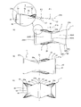
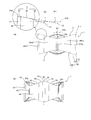
- FIG. 1 It is a figure which shows the cutting insert which concerns on embodiment of this invention, (a) is a perspective view, (b) is a top view (top view). It is a side view which shows the cutting insert shown in FIG. 1, (a) is a X1 arrow view, (b) is a X2 arrow view, (c) is a X3 arrow view. It is a figure which shows the modification of the cutting insert of FIG. 1, (a) is a perspective view, (b) is a top view (top view). It is a side view which shows the cutting insert of FIG. 3, (a) is a Z1 arrow view, (b) is a Z2 arrow view.
- FIGS. 6A and 6B are views showing the cutting insert of FIG. 5, in which FIG. 5A is a side view taken along arrow Z3, FIG. 5B is a cross-sectional view taken along line yy, and FIG. FIG. 6 is a cross-sectional view of the cutting insert of FIG. 5, where (a) is a cross-sectional view taken along the line aa, (b) is a cross-sectional view taken along the line bb, and (c) is a cross-sectional view taken along the line cc.
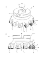
- FIG. 8 It is a figure which shows the cutting tool which concerns on embodiment of this invention
- (a) is a perspective view
- (b) is a side view. It is the side view which expands and shows the attachment state of the cutting insert in the cutting tool of FIG. 8,
- (a) is the figure which looked at the cutting insert from the side surface
- (b) is the figure which looked at the cutting insert from the upper surface.
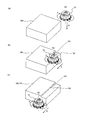
- (A)-(c) is process drawing which shows the manufacturing method of the cut material which concerns on 1st Embodiment of this invention.
- (A)-(c) is process drawing which shows the manufacturing method of the cut material which concerns on 2nd Embodiment of this invention.
- the insert 1 of this embodiment is generally connected to a polygonal (hexagonal) upper surface 2, a lower surface 3 having the same shape as the upper surface 2, and each of the upper surface 2 and the lower surface 3.
- a lower cutting edge 5P located at the intersection with the side surface 4.
- one side of the upper surface 2 may be 5 mm to 100 mm and the thickness of the upper and lower surfaces 2 and 3 may be 3 mm to 100 mm.
- the through hole 6 of the present embodiment is located at the center of each of the upper surface 2 and the lower surface 3.
- the insert 1 of the present embodiment has a hexagonal shape (substantially hexagonal) as shown in FIG.
- the top view means a state in which the insert 1 is viewed from the top surface 2 side.
- the hexagonal shape is not limited to a strict hexagonal shape (regular hexagonal shape), but is a concept including a slight deformation within a range where the function can be exhibited. That is, the hexagonal shape of the present embodiment includes, for example, a case where each side or each vertex has a slight curved shape.
- the insert 1 has three upper corners 2 having three main corners 21 (first to third main corners 21a to 21c) having a first inner angle ⁇ and a second inner angle ⁇ larger than the first inner angle ⁇ .
- Sub-corners 22 (first to third sub-corners 22a to 22c) are alternately provided.
- the insert 1 has lower surfaces 3 alternately having three main corners 21 having a first inner angle ⁇ and three sub-corners 22 having a second inner angle ⁇ larger than the first inner angle ⁇ . Yes.
- the insert 1 has the upper cutting edge 5 and the lower cutting edge 5P of the same shape from the one main corner 21 toward the two sub corners 22 and 22 adjacent to both sides thereof, the three main corners are provided.
- cutting can be performed by rotating both the right hand and the left hand in both directions. That is, according to the insert 1 of this embodiment, each of the three main corners 21 can be used as an insert having substantially six main corners by using the right hand and the left hand.
- the first interior angle ⁇ is preferably substantially a right angle. “Substantially perpendicular” means substantially perpendicular. Specifically, the substantially right angle of the present embodiment includes a range of 90 ° ⁇ 3 °. In particular, the first interior angle ⁇ is preferably larger than 90 °. The second interior angle ⁇ is preferably set within a range of 140 ° to 150 °. In addition, it is preferable that the length of each side is equal from a viewpoint of ensuring large length of the cutting blade which contributes to cutting, using all the sides for cutting.
- the upper cutting edge 5 is located over the entire circumference of the upper surface 2. Thereby, the insert 1 can use the three main corners 21 for cutting.
- the lower surface 3 functions as a seating surface (mounting portion) for partly attaching to the holder 11 described later.
- the insert 1 according to the present embodiment is a so-called negative type in which both the upper surface 2 and the lower surface 3 can be used as surfaces for performing a scooping function, as shown in FIGS. 1 (a) and 2 (a). It is an insert. Therefore, when cutting using the lower cutting edge 5P, a part of the lower surface 3 can be used as a scoop surface and a part of the upper surface 2 can be used as a seating surface (mounting portion). That is, the insert 1 of the present embodiment has a configuration in which the upper surface 2 and the lower surface 3 have the same shape, and the upper and lower surfaces can be used for cutting.
- the description regarding the upper surface 2 is also applied to the lower surface 3 unless otherwise specified.
- the upper surface 2 is a surface having a so-called scooping function for discharging chips, and in order from the upper cutting edge 5 inward, the scooping surface 23 is inclined to the lower surface 3 side, and is away from the lower surface 3 side.
- a planar mounting portion 26 substantially perpendicular to the central axis S1.
- “Inward” means the inside of the insert 1 with respect to the upper cutting edge 5 and means the through-hole 6 side (center axis S1 side).
- the central axis S1 is an axis that penetrates the upper and lower surfaces 2 and 3, and means an axis that becomes a rotation axis when the insert 1 is rotated in a top view.
- the rake face 23 is continuous with the upper cutting edge 5 as shown in FIG. Further, the rake face 23 is inclined downward at the third inclination angle ⁇ 3 toward the lower surface 3 with reference to the vertical plane S1b perpendicular to the central axis S1 from the upper cutting edge 5 toward the central axis S1 ( (See FIG. 7). In the present embodiment, the rake face 23 is located over the entire circumference of the insert 1.
- the third inclination angle ⁇ 3 is preferably set to 10 ° to 30 °.
- the rising surface 24 is continuous with the rake surface 23, and is away from the lower surface 3 with respect to the vertical surface S ⁇ b> 1 b as it goes from the upper cutting edge 5 toward the central axis S ⁇ b> 1 (inward), that is, It is inclined upward at a fourth inclination angle ⁇ 4 (not shown).
- the rising surface 24 is located at a portion corresponding to the three sub corners 22.
- the fourth inclination angle ⁇ 4 is preferably set to 40 ° to 70 °.
- the rake face 23 is continuous with the mounting portion 26 at the portion corresponding to the three main corners 21 and is the rising surface at the portion corresponding to the three sub-corners 22.
- 24 is continuous with the mounting portion 26.
- the mounting portion 26 has a polygonal shape, particularly a triangular shape, when viewed from above as a whole in the insert 1 of the present embodiment.
- the polygonal shape is not limited to having a vertex in a strict sense.
- a connection portion between sides is slightly curved as long as it is necessary to obtain a predetermined effect. It is a concept including the structure which is doing.
- the outer periphery of the through-hole 6 is located inside a region surrounded by a straight line L ⁇ b> 1 that connects the three top portions 26 t of the triangular mounting portion 26 in a top view.
- the top part 26t says the site
- the mounting portion 26 preferably has three separation portions 26a that are separated from each other.
- each of the three separating portions 26 a of the insert 1 can be brought into contact with the corresponding contact surface of the holder 11 separately, so that attachment stability to the holder 11 is improved. It becomes possible to improve.
- the three separating portions 26 a are independent from each other, and thus undergo another process such as polishing. It is possible to make the contact with the contact surface of the holder 11 relatively strong.
- each of the three separation portions 26a has a triangular shape in a top view.
- one triangular top portion of the separation portion 26 a is closest to the main corner 21.
- the mounting portion 26 on the lower surface 3 side is a surface that contacts the holder 11. The reverse is also true.
- the mounting portion 26 on the lower surface 2 side has an end portion located on the central axis S1 side with respect to the end portion located on the lower cutting edge 5P side, that is, on the upper surface 2 side with respect to the vertical surface S1b. Located above. In other words, the mounting portion 26 on the lower surface 2 side has an outer peripheral region located outside the center region in the thickness direction of the insert 1. Thereby, when attaching to the holder 11, the end located on the lower cutting edge 5 ⁇ / b> P side is brought into relatively strong contact with the corresponding contact surface of the holder 11 and is located on the center axis S ⁇ b> 1 side.
- the attachment to the holder 11 by the end portion located on the lower cutting edge 5P side is located on the central axis S1 side. It can assist by the edge part which is, and it becomes possible to improve the attachment stability with respect to the holder 11.
- FIG. The inclination angle from the central region to the outer peripheral region of the mounting portion 26 on the lower surface 2 side is preferably set to 80 ° to 90 °.
- the upper surface 2 further has a recess 25 positioned around the through hole 6 on the lower surface 3 side, that is, below the mounting portion 26, and the above three separations.
- the portions 26 a are separated from each other via the through hole 6 and the recess 25.
- each of the three separating portions 26a can be brought into contact with the corresponding contact surface of the holder 11 more reliably, thereby further improving the attachment stability to the holder 11 as described above. It becomes possible to make it.
- the upper cutting edge 5 has a corner cutting edge 51, a secondary cutting edge 52, and a main cutting edge 53 as shown in FIG. Specifically, as shown in FIGS. 1B and 2A, the upper cutting edge 5 is formed of, for example, the first main corner 21a to the three sub corners 22 out of the three main corners 21. In order toward each of the first sub-corner 22a and the second sub-corner 22b adjacent to the first main corner 21a, the lower the corner cutting edge 51, the lower the corner cutting edge 51, that is, with respect to the vertical plane S1b.
- the secondary cutting edge 52 that is inclined toward the lower surface 3 at the first inclination angle ⁇ 1 and the lower side from the auxiliary cutting edge 52, that is, from the first inclination angle ⁇ 1 toward the lower surface 3 with respect to the vertical surface S1b.
- the first inclination angle ⁇ 1 is preferably set to 3 ° to 15 °
- the second inclination angle ⁇ 2 is preferably set to 7 ° to 19 °.
- the first inclination angle ⁇ 1 means an angle formed by the vertical plane S1b and the virtual extension line L2 of the auxiliary cutting edge 52
- the second inclination angle ⁇ 2 is the vertical plane S1b. It means the angle formed by the virtual extension line L3 of the main cutting edge 53.
- the virtual extension line L2 means a straight line obtained by extending the tangent at the starting point of the auxiliary cutting edge 52, that is, the end of the auxiliary cutting edge 52 located on the corner cutting edge 51 side.
- the virtual extension line L3 means a straight line obtained by extending the tangent at the starting point of the main cutting edge 53, that is, the end of the main cutting edge 53 located on the sub cutting edge 52 side.
- the corner cutting edge 51 is located at the intersection of a later-described main corner side face 41 and the upper face 2 of the side face 4, and the upper cutting edge 5 is lost due to the cutting force applied during the cutting process. And has a curved shape in a top view.
- the corner cutting edge 51 is perpendicular to the central axis S1 and parallel to the vertical plane S1b.
- the auxiliary cutting edge 52 is located on the corner cutting edge 51 side in the intersecting portion between the first side face 42 and the upper face 2 described later. Further, as shown in FIG. 1B, the auxiliary cutting edge 52 is a cutting edge having a role as the first and second main cutting portions 5a and 5c together with the main cutting edge 53. At the same time, the auxiliary cutting edge 52 is a cutting edge having a role of mainly improving the accuracy of the finished surface 102 of the work material 100 described later, a so-called wiping edge. In the present embodiment, the auxiliary cutting edge 52 is linear.
- the main cutting edge 53 is located on the first sub-corner 22a side in the intersecting portion of the first side surface 42 and the upper surface 2, and plays a main role in chip generation in the cutting process. It has a cutting blade.
- the main cutting edge 53 is concave on the lower surface 3 side in a side view.
- the side view means a state in which the insert 1 is viewed from the side surface 4 side.
- the connecting portion 54 between the main cutting edge 53 and the auxiliary cutting edge 52 is preferably set so as to bend in a direction away from the lower surface 3, that is, upward within a range of R1.0 to R10.0.
- the upper cutting edge 5 is inclined toward the lower surface 3 as it goes to the corner cutting edge 51, the auxiliary cutting edge 52, and the main cutting edge 53, so that a high cutting edge strength is provided on the corner cutting edge 51 side. At the same time, it is possible to realize a low cutting resistance on the main cutting edge 53 side.
- the thickness of the insert 1 is decreasing as it goes to the corner cutting edge 51, the sub cutting edge 52, and the main cutting edge 53, the distance from the through-hole 6 to each cutting edge in top view becomes large in connection with it. Therefore, it is possible to ensure a high cutting edge strength in each cutting edge region.
- the lower cutting edge 5P has a corner cutting edge 51P, a secondary cutting edge 52P, and a main cutting edge 53P.
- the configuration of the corner cutting edge 51P, the auxiliary cutting edge 52P, and the main cutting edge 53P is the same as that of the corner cutting edge 51, the auxiliary cutting edge 52, and the main cutting edge 53.
- the side surface 4 is a surface functioning as a so-called escape portion for suppressing contact with the work material 100, and in the present embodiment, is perpendicular to the upper surface 2 and the lower surface 3 as shown in FIG. Therefore, compared to an insert having a clearance angle between the side surface and the upper surface 2 or the lower surface 3, the thickness of the insert 1 can be ensured, so that the insert 1 has excellent fracture resistance.
- the side surface 4 connected to the hexagonal upper surface 2 has a main corner side surface 41 from the first main corner 21a toward the second main corner 21b as shown in FIG.
- the first side surface 42, the sub-corner side surface 43, and the second side surface 44 are provided in this order.
- the first side surface 42 and the second side surface 44 are both flat surfaces, and the main corner side surface 41 and the sub-corner side surface 43 are both curved surfaces.
- the through-hole 6 has a role of fixing the insert 1 to a holder 11 described later. That is, the insert screw 12 (fixing member) is inserted into the through hole 6 and further screwed into the holder 11 to fix the insert 1 to the holder 11 and form the cutting tool 10.
- the central axis of the through-hole 6 exists in the same position as the central axis S1.
- the upper cutting edge 5 has the corner cutting edge 51, the sub cutting edge 52, and the main cutting edge 53 similarly to the cutting insert 1 which concerns on the above-mentioned embodiment.
- the upper cutting edge 5 of the present modification has three sub-corners from, for example, the first main corner 21a among the three main corners 21. 22 in order toward each of the first sub-corner 22a and the second sub-corner 22b adjacent to the first main corner 21a, with the vertical plane S1b as a reference as the distance from the corner cutting edge 51 increases.
- the secondary cutting edge 52 that is inclined toward the lower surface 3 at the first inclination angle ⁇ 1, and the larger the first inclination angle ⁇ 1 toward the lower surface 3 with respect to the vertical surface S1b as the distance from the auxiliary cutting edge 52 increases,
- the main cutting edge 53 is inclined at the second inclination angle ⁇ 2.
- the upper cutting edge 5 of this modified example has a secondary cutting edge 52 that is linear, and the main cutting edge 53 is continuous with the auxiliary cutting edge 52 and is located on the lower surface 3 side in a side view. It is concave.
- the rake face 23 of the present modification is located inside the corner rake face 231 positioned inward of the corner cutting edge 51 and inward of the auxiliary cutting edge 52.
- a secondary rake face 232 and a main rake face 233 positioned inward of the main cutting edge 53.
- the angle ⁇ z formed by the auxiliary rake face 232 and the main rake face 233 is defined by the auxiliary cutting edge 52 and the main cutting edge 53. It is substantially the same as the angle ⁇ x. According to this, the upper cutting edge 5 is damaged at a portion where the cutting edge strength is relatively small in the vicinity of the boundary between the secondary cutting edge 52 that is linear and the main cutting edge 53 that is concave on the lower surface 3 side. Can be reduced. As a result, the insert 1 of the present modification can also be used in so-called heavy cutting.
- the angle ⁇ y is substantially the same as the angle ⁇ x and the angle ⁇ z.
- angles ⁇ z and ⁇ y mean the angles formed by the virtual extension line L4 of the auxiliary rake face 232 and the virtual extension line L5 of the main rake face 233.
- the virtual extension line L4 means a straight line obtained by extending the tangent at the starting point of the sub rake face 232, that is, the end portion of the sub rake face 232 located on the corner rake face 231 side.
- the virtual extension line L5 means a straight line obtained by extending the tangent at the start point of the main rake face 233, that is, the end portion of the main rake face 233 located on the sub rake face 232 side.
- the angle ⁇ x means an angle formed by the virtual extension line L2 of the sub cutting edge 52 and the virtual extension line L3 of the main cutting edge 53.
- the fact that the angles ⁇ x, ⁇ y, ⁇ z are substantially the same means that there may be a difference of ⁇ 1 ° between them.
- the angle ⁇ z may be smaller than the angle ⁇ x. According to this, since the strength of the corresponding rake face 23 can be increased in a portion having a relatively small cutting edge strength in the vicinity of the boundary between the sub cutting edge 52 and the main cutting edge 53, damage to the cutting edge is reduced. It becomes possible to do.
- the boundary 23 a between the auxiliary rake face 232 and the main rake face 233 is a cutting edge between the auxiliary cutting edge 52 and the main cutting edge 53 as viewed from above.
- the boundary 5A extends in a direction substantially perpendicular to the tangent L6 at the cutting edge boundary 5A. According to this, during cutting, a relatively large cutting force applied in the vicinity of the cutting edge boundary 5A between the sub cutting edge 52 and the main cutting edge 53 is applied to the boundary 23a between the sub rake face 232 and the main rake face 233. It can be received with strength, and the upper cutting edge 5 can reduce damage at the cutting edge boundary 5A between the auxiliary cutting edge 52 and the main cutting edge 53.
- substantially vertical means substantially vertical.
- the substantially vertical direction of the present modification includes a range in which the angle formed by the boundary 23a and the tangent line L6 is 90 ° ⁇ 3 °.
- the boundary 23a between the sub rake face 232 and the main rake face 233 located between the first main corner 21a and the first sub corner 22a is The distance H from the straight line L7 connecting the first main corner 21a and the second sub corner 22b is substantially constant. Also in this configuration, the upper cutting edge 5 is damaged at a portion having a relatively small cutting edge strength in the vicinity of the cutting edge boundary 5A between the secondary cutting edge 52 that is linear and the main cutting edge 53 that is concave on the lower surface 3 side. Can be reduced.
- the straight line L7 will be described in more detail.
- the straight line L7 includes the end 21a1 located on the second sub-corner 22b side of the first main corner 21a and the first main of the second sub-corner 22b. It is a straight line connecting the end 22b1 located on the corner 21a side.
- substantially constant means equivalent to substantially constant.
- the distance H may be increased as the distance from the cutting blade 5 increases. Even in this case, it is possible to reduce damage to the cutting edge in a portion where the cutting edge strength is relatively small near the boundary between the sub cutting edge 52 and the main cutting edge 53.
- the third inclination angle ⁇ 3 of the rake face 23 includes the rake angle ⁇ 31 of the minor rake face 232, the rake angle ⁇ 32 of the boundary 23a between the minor rake face 232 and the major rake face 233, and the major rake face 233.
- the rake angle ⁇ 33 is substantially constant. According to this, at the time of cutting, since the cutting force is not locally applied and dispersed in the region from the sub rake face 232 to the main rake face 233, the boundary 23a between the sub cutting edge 52 and the main cutting edge 53 is obtained. It becomes possible to reduce damage in the case.
- substantially constant means that it is substantially equal to the constant as described above.
- the cutting edge strength at the boundary 23a between the auxiliary cutting edge 52 and the main cutting edge 53 may be further improved by satisfying the relationship of ⁇ 32 ⁇ 31 and ⁇ 32 ⁇ 33.
- the third inclination angle ⁇ 3 of the rake face 23 may be increased as it goes inward. According to this, since the strength of the corresponding rake face 23 can be increased in a portion having a relatively small cutting edge strength in the vicinity of the boundary between the sub cutting edge 52 and the main cutting edge 53, damage to the cutting edge is reduced. It becomes possible to do.
- the width W of the rake face 23 decreases as it goes from the first main corner 21a to the first sub-corner 22a, as shown in FIGS. That is, the width W of the rake face 23 of this modification is W1> W2> W3 as shown in FIG. As another example, by setting the width W of the rake face 23 such that W2> W1 and W2> W3, the cutting edge strength at the cutting edge boundary 5A between the auxiliary cutting edge 52 and the main cutting edge 53 is shown. You may make it improve more.
- connection surface 23b functions as a escape portion for chips passing through the rake surface 23, and is also a portion that contributes to ensuring a large area of the placement portion 26.
- the mounting portion 26 has a hexagonal shape in a top view. Thereby, since it can attach to the holder 11 using six hexagonal top parts 26t, the attachment stability with respect to the holder 11 can be improved.
- the upper surface 2 has a recess 25, but the mounting portion 26 of this modification is integrally formed without being separated.
- the six top portions 26t of the mounting portion 26 are three main top portions 26t1 located corresponding to the three main corners 21 and three sub-top portions located corresponding to the three sub corners 22. 26t2.
- each top part 26t is located corresponding to the corner part which receives a comparatively big cutting force at the time of cutting, chatter vibration can be reduced by attaching to the holder 11 in the said part. Damage to the upper cutting edge 5 can be reduced.
- the three main top portions 26t1 have a larger distance from the central axis S1 than the three sub top portions 26t2. That is, the main top portion 26t1 and the sub-top portion 26t2 of this modification satisfy the relationship D1> D2, as shown in FIG. As a result, the cutting edge regions functioning as the first and second main cutting portions 5a and 5c can be brought into contact with the holder 11 using the three main top portions 26t1 located at locations relatively far from the central axis S1. At the same time, since the other sub-tops 26t2 can be used to contact the holder 11 in the other areas, the three main tops 26t1 can be attached to the holder 11 by the three sub-tops 26t2. The attachment stability with respect to the holder 11 can be improved.
- the three main top portions 26t1 are located farther from the upper surface 2 with respect to the vertical surface S1b, that is, below the three sub-top portions 26t2.
- the three main top portions 26t1 can be brought into relatively strong contact with the corresponding contact surfaces of the holder 11, and Since the three sub-tops 26t2 can also be brought into relatively weak contact with the corresponding contact surfaces of the holder 11, the three sub-tops 26t2 can assist the attachment to the holder 11 by the three main tops 26t1. It is possible to improve the attachment stability to the holder 11.
- the mounting portion 26 on the upper surface 2 is located on the lower surface 3 side (downward) from any part of the upper cutting blade 5 in a side view, as shown in FIG. Yes.
- the insert 1 of this modification has the same thickness between the upper and lower mounting portions 26 as compared to the insert 1 of the above-described embodiment, whereas the upper surface 2 to the lower surface 3. In both the maximum thickness and the minimum thickness in the thickness direction, the thickness is set to a value larger than the thickness between the mounting portions 26 on the upper and lower surfaces.
- the distance between the upper cutting edge 5 and the mounting portion 26 on the upper surface 2 is increased, so that a large space for generating chips can be ensured, and chip discharge performance can be improved.
- the placement portion 26 is positioned on the lower surface 3 side with respect to the upper cutting edge 5 as described above.
- it is difficult to shape by the polishing process but by providing the mounting portion 26 with an inclination, it is possible to stably contact the contact surface of the holder 11 without performing the polishing process. Is possible.
- the cutting tool 10 of the present embodiment includes a plurality of inserts 1 described above and a holder 11 to which the plurality of inserts 1 are attached using a fixing member.
- the holder 11 has a plurality of insert pockets 11a at the outer peripheral tip. And the insert 1 is attached to the outer peripheral position in each insert pocket 11a. Specifically, when the cutting tool 10 is rotated in the direction of arrow A in FIG. 8A, the insert 1 has the upper surface (rake surface) 2 facing the front side of the arrow A that is the rotation direction, and the holder 11 is attached so that the main cutting edge 53 is positioned on the outermost periphery of the motor 11. As an attachment method, the plurality of inserts 1 are respectively fixed to the holder 11 by inserting attachment screws 12 (fixing members) into the respective through holes 6 of the plurality of inserts 1 and screwing them into the holders 11.
- attachment screws 12 fixing members
- the insert 1 is adjacent to the first main corner 21a of the upper cutting edge 5 with reference to a parallel surface S2a parallel to the rotation axis S2 of the holder 11.
- the first rake angle ⁇ a of the first main cutting portion 5a across the first sub-corner 22a is positive, and the non-cut across the second main corner 21b adjacent to the first sub-corner 22a of the upper cutting edge 5
- the cutting part 5b is attached to the holder 11 in such a state that the axial rake angle ⁇ b is negative.
- the first main cutting portion 5a includes a sub cutting edge 52 and a main cutting edge 53.
- the axial rake angle ⁇ a is positive in both the sub cutting edge 52 and the main cutting edge 53. is there.
- the axial rake angle of the auxiliary cutting edge 52 is preferably set to 0 ° to 10 °
- the axial rake angle of the main cutting edge 53 is preferably set to 5 ° to 20 °.
- the axial rake angle ⁇ a for example, for a curved cutting edge like the main cutting edge 53, extends the tangent at the starting point of the main cutting edge 53, that is, the end located on the sub cutting edge 52 side. What is necessary is just to measure using the straight line L8.
- the axial rake angle ⁇ b may be measured using, for example, a straight line L9 obtained by extending a tangent at the starting point of the non-cutting portion 5b, that is, the end located on the first sub-corner 22a side.
- the insert 1 is in a state where the axial rake angle ⁇ c of the straight line L10 connecting the first main corner 21a and the second main corner 21b of the upper cutting edge 5 is negative. And attached to the holder 11.
- the axial rake angle as a whole including the first main cutting portion 5a and the non-cutting portion 5b is negative.
- the cutting tool 10 is configured by attaching the insert 1 to the holder 11 as described above. By rotating such a cutting tool 10 in the direction of arrow A, it is possible to perform cutting such as face milling and plunge machining on the work material 100 as described later.
- the work material 100 is cut using the first main cutting portion 5a of the insert 1 to form the cutting surface 101, and the sub surface is cut.
- the finished surface 102 can be formed by cutting the workpiece 100 using the cutting edge 52.
- the auxiliary cutting edge 52 is set in a substantially parallel relationship with respect to the vertical surface S2b perpendicular to the rotation axis S2 of the holder 11.
- the manufacturing method of the cut workpiece of the first and second embodiments includes a step of rotating the cutting tool 10 described above with reference to the rotation axis S2 of the holder 11, and an upper cutting edge 5 of the rotating cutting tool 10 covered. A step of contacting the surface of the work material 100 and a step of separating the cutting tool 10 from the work material 100.
- the manufacturing method of the cut workpiece according to the present embodiment includes the following steps (i) to (iii).
- the order when the order which performs each process is not specified, the order may be changed suitably.
- the first main cutting portion 5 a extending from the first main corner 21 a to the first sub-corner 22 a adjacent to the upper cutting edge 5 of the rotating cutting tool 10 is formed on the surface of the work material 100.
- the process of making it contact As a result, the cut surface of the work material 100 cut in contact with the first main cutting portion 5a becomes a cut surface 101 as shown in FIG.
- the auxiliary cutting edge 52 located between the first main corner 21a and the second auxiliary corner 22b in the upper cutting edge 5 of the rotating cutting tool 10 is replaced with the first main cutting portion 5a.
- the process of making it contact the work surface of the work material 100 formed by contacting.
- the portion of the work surface of the work material 100 cut by the first main cutting portion 5a in the second step described above that is left uncut without being directly cut by the first main cutting portion 5a is sub-cut. Smoothed by the blade 52, a finished surface 102 as shown in FIG.
- a cut workpiece 110 is manufactured by cutting the workpiece 100 into a desired shape as shown in FIG.
- the process which maintains the state which rotated the cutting tool 10, for example, and makes the upper cutting blade 5 of the cutting tool 10 contact the different location of the workpiece 100 is carried out. Repeat it.
- the main corner 21 of the upper cutting edge 5 used for cutting is worn, the main corner 21 of the unused upper cutting edge 5 is used by rotating the insert 1 120 ° with respect to the central axis S1. That's fine.
- the one main corner 21 of the insert 1 can be used for reverse-handed cutting by rotating the rotation direction of the cutting tool 10 in the direction opposite to the arrow A, 3 By using each of the main corners 21 for both the right hand and the left hand, it can be used as an insert having substantially six main corners.
- the auxiliary cutting edge 52 in the first main cutting portion 5a has a role as a cutting edge for forming the finished surface 102.
- the upper cutting edge 5 has been described, but the same applies to the lower cutting edge 5P.
- each process mentioned above can be modified as follows.
- the work material 100 may be rotated while the cutting tool 10 is fixed.
- the cutting tool 10 and the work material 100 may be relatively close to each other.
- the work material 100 may be close to the cutting tool 10.
- the work material 100 and the cutting tool 10 need only be relatively distant from each other.
- the work material 100 may be kept away from the cutting tool 10 held at a predetermined position. Good. The same applies to the second embodiment described below.
- the manufacturing method of the cut workpiece according to the present embodiment includes the following steps (i) to (iii).
- the order when the order which performs each process is not specified, the order may be changed suitably.
- the second main cutting portion 5c extending from the first main corner 21a to the second sub corner 22b adjacent to the upper cutting edge 5 of the rotating cutting tool 10 is formed on the surface of the work material 100. The process of making it contact.
- the cut surface of the work material 100 cut in contact with the second main cutting portion 5c becomes a cut surface 101 as shown in FIG.
- the secondary cutting edge 52 located between the first primary corner 21a and the first secondary corner 22a in the upper cutting edge 5 of the rotating cutting tool 10 is replaced with the second primary cutting portion 5c.
- the process of making it contact the work surface of the work material 100 formed by contacting.
- the portion of the work surface of the work material 100 cut by the second main cutting portion 5c in the second step described above that is left uncut without being directly cut by the second main cutting portion 5c is sub-cut. Smoothed by the blade 52, a finished surface 102 as shown in FIG.
- a cut workpiece 110 is manufactured by cutting the workpiece 100 into a desired shape as shown in FIG.
- the colors of the upper surface 2 and the lower surface 3 may be different from each other.
- the insert body is a cemented carbide showing a silver color
- TiN titanium nitride
- both the upper surface 2 and the lower surface 3 function as rake surfaces, which may cause an erroneous mounting of the insert.
- the surface coated with TiN and the surface not coated have different colors.
- the coating target surface of either the upper surface 2 or the lower surface 3 does not need to cover the entire surface, and, for example, the same applies by coating TiN on a part of the coating target surface (for example, a portion other than the cutting edge). The effect of can be obtained.
- the material used for the coating is not limited to TiN as long as the color difference between the upper surface 2 and the lower surface 3 can be recognized.
- TiCN titanium carbonitride
- TiAlN titanium nitride aluminum
- the upper cutting edge 5 may have a land (not shown) substantially parallel to the vertical surface S1b. As a result, the strength of the upper cutting edge 5 can be improved, and it can be suitably used even under so-called heavy cutting processing conditions.
- the upper surface 2 has a hexagonal shape
- the upper surface 2 may have a polygonal shape other than the hexagonal shape.
Abstract
Description
そこで、低い切削抵抗と優れた耐欠損性を兼ね備えるインサートが求められている。
以下、本発明の実施形態に係る切削インサートについて、図1および図2を参照して詳細に説明する。
上面2は、切屑を排出するための所謂すくいの機能を有する面であり、上切刃5から内方に向かって順に、下面3側に傾斜しているすくい面23、下面3側から遠ざかるように傾斜している立ち上がり面24、および、中心軸S1に略垂直な平面状の載置部26(着座面)を有している。内方とは、上切刃5に対してインサート1の内側であり、貫通孔6側(中心軸S1側)のことを意味するものとする。中心軸S1とは、上下面2、3を貫く軸であり、上面視において、インサート1を回転させたときに回転軸となる軸を意味するものとする。
次に、上述の実施形態に係るインサート1の変形例について、図3~図7を参照して詳細に説明する。
次に、本発明の実施形態に係る切削工具について、図8および図9を参照して詳細に説明する。
次に、本発明の第1、第2実施形態に係る切削加工物の製造方法について、図10および図11を参照して、詳細に説明する。
第1実施形態に係る切削加工物の製造方法として、いわゆる正面フライス加工を例にとって、図10を参照して詳細に説明する。
次に、第2実施形態に係る切削加工物の製造方法として、いわゆるプランジ加工(突き加工)を例にとって、図11を参照して詳細に説明する。
Claims (20)
- 多角形状の上面と、
前記上面と同一形状の下面と、
前記上面および前記下面のそれぞれと接続している側面と、
前記上面と前記側面との交線部に位置している上切刃と、を備え、
前記上面は、第1内角を備える3つの主コーナーと、前記第1内角よりも大きい第2内角を備える3つの副コーナーと、を交互に有し、
前記上切刃は、前記3つの主コーナーのうちの第1主コーナーから前記3つの副コーナーのうちの前記第1主コーナーに隣接している第1副コーナーおよび第2副コーナーのそれぞれに向かって順に、コーナー切刃、前記コーナー切刃から離れるにつれて前記上下面を貫く中心軸に垂直な垂直面を基準にして前記下面に向かって第1傾斜角で傾斜している副切刃、および、前記副切刃から離れるにつれて前記垂直面を基準にして前記下面に向かって前記第1傾斜角よりも大きい第2傾斜角で傾斜している主切刃を有している、切削インサート。 - 前記コーナー切刃は前記垂直面に平行である、請求項1に記載の切削インサート。
- 前記主切刃は側面視において前記下面側に凹状である、請求項1または2に記載の切削インサート。
- 前記副切刃は直線状である、請求項1~3のいずれかに記載の切削インサート。
- 前記第1内角は略直角である、請求項1~4のいずれかに記載の切削インサート。
- 前記第1内角は90°よりも大きい、請求項5に記載の切削インサート。
- 前記上面から前記下面まで貫通している貫通孔、をさらに備える請求項1~6のいずれかに記載の切削インサート。
- 前記上面は、前記上切刃に連続しており、前記上切刃から内方に向かうにつれて前記垂直面を基準にして前記下面に向かって第3傾斜角で傾斜しているすくい面、をさらに有しており、
前記すくい面は、前記副切刃の内方に位置している副すくい面と、前記主切刃の内方に位置している主すくい面と、を有している、請求項1~7のいずれかに記載の切削インサート。 - 前記副すくい面と前記主すくい面とのなす角の角度は、前記副切刃と前記主切刃とのなす角の角度と実質的に同一である、請求項8に記載の切削インサート。
- 上面視において、前記第1主コーナーと前記第1副コーナーとの間に位置している前記副すくい面と前記主すくい面との境界は、前記第1主コーナーと前記第2副コーナーとを結ぶ直線からの距離が実質的に一定である、請求項9に記載の切削インサート。
- 上面視において、前記副すくい面と前記主すくい面との境界は、前記副切刃と前記主切刃との切刃境界から該切刃境界における接線に対して略垂直な方向に延びている、請求項9または10に記載の切削インサート。
- 前記すくい面の前記第3傾斜角は、前記副すくい面、前記副すくい面と前記主すくい面との境界、および前記主すくい面において実質的に一定である、請求項8~11のいずれかに記載の切削インサート。
- 前記すくい面の幅は、前記第1主コーナーから前記第1副コーナーに向かうにつれて小さくなっている、請求項8~12のいずれかに記載の切削インサート。
- 前記上面は、前記すくい面に連続しており、前記上切刃から内方に向かうにつれて前記垂直面を基準にして前記下面から離れる方向に向かって第4傾斜角で傾斜している立ち上がり面、をさらに有する、請求項8~13のいずれかに記載の切削インサート。
- 前記上面は、平面状の載置部、をさらに有し、
前記すくい面は、前記3つの主コーナーに対応する部位において前記載置部と連続しているとともに、前記3つの副コーナーに対応する部位において前記立ち上がり面を介して前記載置部と連続している、請求項14に記載の切削インサート。 - 請求項1~15のいずれかに記載の切削インサートと、
前記切削インサートが取り付けられるホルダと、を備え、
前記切削インサートは、前記上切刃のうち前記第1主コーナーから隣接している前記第1副コーナーに渡る第1主切削部のアキシャルレーキ角が正であり、且つ、前記上切刃のうち前記第1副コーナーから隣接している第2主コーナーに渡る非切削部のアキシャルレーキ角が負である、切削工具。 - 前記切削インサートは、前記上切刃のうち前記第1主コーナーと前記第2主コーナーとを結ぶ直線のアキシャルレーキ角が負である、請求項16に記載の切削工具。
- 請求項16または17に記載の切削工具を前記ホルダの回転軸を基準に回転させる工程と、
回転している前記切削工具の前記上切刃を被削材の表面に接触させる工程と、
前記切削工具を前記被削材から離隔する工程と、を備える、切削加工物の製造方法。 - 前記上切刃を被削材の表面に接触させる工程は、
回転している前記切削工具を、前記回転軸に対して垂直な方向に移動させる工程と、
回転している前記切削工具の前記上切刃のうち前記第1主コーナーから隣接している前記第1副コーナーに渡る第1主切削部を、被削材の表面に接触させる工程と、
回転している前記切削工具の前記上切刃のうち前記第1主コーナーと前記第2副コーナーとの間に位置している前記副切刃を、前記第1主切削部と接触することによって形成された前記被削材の被削面に接触させる工程と、を有する、請求項18に記載の切削加工物の製造方法。 - 前記上切刃を被削材の表面に接触させる工程は、
回転している前記切削工具を、前記回転軸に対して平行な方向に移動させる工程と、
回転している前記切削工具の前記上切刃のうち前記第1主コーナーから隣接している前記第2副コーナーに渡る第2主切削部を、被削材の表面に接触させる工程と、
回転している前記切削工具の前記上切刃のうち前記第1主コーナーと前記第1副コーナーとの間に位置している前記副切刃を、前記第2主切削部と接触することによって形成された前記被削材の被削面に接触させる工程と、を有する、請求項18に記載の切削加工物の製造方法。
Priority Applications (6)
| Application Number | Priority Date | Filing Date | Title |
|---|---|---|---|
| EP12776064.3A EP2703108B2 (en) | 2011-04-28 | 2012-04-27 | Cutting insert, cutting tool, and method for producing cut producing using same |
| KR1020137027670A KR101547510B1 (ko) | 2011-04-28 | 2012-04-27 | 절삭 인서트 및 절삭 공구, 그리고 그것을 이용한 절삭 가공물의 제조 방법 |
| US14/113,552 US9533356B2 (en) | 2011-04-28 | 2012-04-27 | Cutting insert, cutting tool, and method of manufacturing machined product using the same |
| JP2013512469A JP5715688B2 (ja) | 2011-04-28 | 2012-04-27 | 切削インサートおよび切削工具、並びにそれを用いた切削加工物の製造方法 |
| CN201280019701.9A CN103492109B (zh) | 2011-04-28 | 2012-04-27 | 切削镶刀、切削工具以及使用切削工具切削加工物的方法 |
| US15/358,698 US10058937B2 (en) | 2011-04-28 | 2016-11-22 | Cutting insert, cutting tool, and method of manufacturing machined product using the same |
Applications Claiming Priority (4)
| Application Number | Priority Date | Filing Date | Title |
|---|---|---|---|
| JP2011-101190 | 2011-04-28 | ||
| JP2011101190 | 2011-04-28 | ||
| JP2012-044134 | 2012-02-29 | ||
| JP2012044134 | 2012-02-29 |
Related Child Applications (2)
| Application Number | Title | Priority Date | Filing Date |
|---|---|---|---|
| US14/113,552 A-371-Of-International US9533356B2 (en) | 2011-04-28 | 2012-04-27 | Cutting insert, cutting tool, and method of manufacturing machined product using the same |
| US15/358,698 Continuation US10058937B2 (en) | 2011-04-28 | 2016-11-22 | Cutting insert, cutting tool, and method of manufacturing machined product using the same |
Publications (1)
| Publication Number | Publication Date |
|---|---|
| WO2012147923A1 true WO2012147923A1 (ja) | 2012-11-01 |
Family
ID=47072435
Family Applications (1)
| Application Number | Title | Priority Date | Filing Date |
|---|---|---|---|
| PCT/JP2012/061389 WO2012147923A1 (ja) | 2011-04-28 | 2012-04-27 | 切削インサートおよび切削工具、並びにそれを用いた切削加工物の製造方法 |
Country Status (6)
| Country | Link |
|---|---|
| US (2) | US9533356B2 (ja) |
| EP (1) | EP2703108B2 (ja) |
| JP (1) | JP5715688B2 (ja) |
| KR (1) | KR101547510B1 (ja) |
| CN (2) | CN106270705B (ja) |
| WO (1) | WO2012147923A1 (ja) |
Cited By (3)
| Publication number | Priority date | Publication date | Assignee | Title |
|---|---|---|---|---|
| JP5639710B2 (ja) * | 2011-04-28 | 2014-12-10 | 京セラ株式会社 | 切削インサートおよび切削工具、並びにそれを用いた切削加工物の製造方法 |
| WO2015104703A1 (en) | 2014-01-09 | 2015-07-16 | Iscar Ltd. | Double-sided indexable cutting insert and cutting tool therefor |
| WO2015199031A1 (ja) * | 2014-06-27 | 2015-12-30 | 京セラ株式会社 | 切削インサート、切削工具及び切削加工物の製造方法 |
Families Citing this family (19)
| Publication number | Priority date | Publication date | Assignee | Title |
|---|---|---|---|---|
| WO2012147923A1 (ja) * | 2011-04-28 | 2012-11-01 | 京セラ株式会社 | 切削インサートおよび切削工具、並びにそれを用いた切削加工物の製造方法 |
| US9770767B2 (en) * | 2011-05-31 | 2017-09-26 | Kyocera Corporation | Cutting insert, cutting tool, and method of manufacturing machined product using the same |
| CN103619517B (zh) * | 2011-06-30 | 2016-04-06 | 京瓷株式会社 | 切削镶刀及切削工具、以及使用该切削工具的切削加工物的制造方法 |
| EP2774705B1 (en) * | 2011-10-31 | 2020-12-23 | Kyocera Corporation | Cutting insert, cutting tool, and method for manufacturing cutting workpiece using same |
| CN107297531B (zh) | 2011-10-31 | 2019-11-22 | 京瓷株式会社 | 切削镶刀 |
| US9296054B2 (en) * | 2013-05-23 | 2016-03-29 | Kennametal Inc. | Indexable cutting insert with a triangular shape |
| CN104162704A (zh) * | 2014-07-14 | 2014-11-26 | 株洲钻石切削刀具股份有限公司 | 一种多功能铣削刀片及刀具 |
| WO2016017470A1 (ja) * | 2014-07-29 | 2016-02-04 | 京セラ株式会社 | 切削インサート、切削工具及び切削加工物の製造方法 |
| CN104439461B (zh) * | 2014-11-04 | 2017-01-18 | 厦门金鹭特种合金有限公司 | 一种负型铣削刀片 |
| EP3059037B1 (en) * | 2015-02-20 | 2023-08-02 | Seco Tools Ab | Double-sided high feed milling insert, high feed milling tool and method |
| DE102016109452A1 (de) * | 2016-05-23 | 2017-11-23 | Hartmetall-Werkzeugfabrik Paul Horn Gmbh | Schneidplatte für ein Fräswerkzeug und Fräswerkzeug |
| BR112019004787A2 (pt) * | 2016-10-14 | 2019-06-04 | Sumitomo Electric Hardmetal Corp | inserto de corte |
| US10112242B1 (en) * | 2017-04-21 | 2018-10-30 | Iscar, Ltd. | Ramping insert having non-positive cutting geometry and ramping tool |
| CN109475951B (zh) * | 2017-04-25 | 2020-10-16 | 住友电工硬质合金株式会社 | 切削刀具 |
| EP3845338A4 (en) * | 2018-08-30 | 2022-06-08 | Mitsubishi Materials Corporation | CUTTING INSERT AND CUTTING TOOL OF CUTTING EDGE REPLACEMENT TYPE |
| JP7119780B2 (ja) * | 2018-08-30 | 2022-08-17 | 三菱マテリアル株式会社 | 切削インサートおよび刃先交換式切削工具 |
| JP7119781B2 (ja) * | 2018-08-30 | 2022-08-17 | 三菱マテリアル株式会社 | 切削インサートおよび刃先交換式切削工具 |
| JP6744599B1 (ja) * | 2019-03-01 | 2020-08-19 | 株式会社タンガロイ | 切削インサート |
| JP7011689B1 (ja) * | 2020-08-11 | 2022-01-27 | 株式会社タンガロイ | 切削インサート及び回転切削工具 |
Citations (6)
| Publication number | Priority date | Publication date | Assignee | Title |
|---|---|---|---|---|
| JPH08323510A (ja) * | 1995-06-01 | 1996-12-10 | Mitsubishi Materials Corp | スローアウェイチップ及びスローアウェイ式カッタ |
| JPH09216113A (ja) | 1996-02-13 | 1997-08-19 | Sumitomo Electric Ind Ltd | スローアウェイチップおよび切削工具 |
| JP2002046010A (ja) * | 2000-05-23 | 2002-02-12 | Mitsubishi Materials Corp | スローアウェイチップ及びスローアウェイ式カッタ |
| WO2007037733A1 (en) | 2005-09-28 | 2007-04-05 | Seco Tools Ab | A milling insert and a milling tool |
| WO2007142224A1 (ja) * | 2006-06-06 | 2007-12-13 | Mitsubishi Materials Corporation | 切削工具及び切削インサート |
| JP2010523352A (ja) * | 2007-04-01 | 2010-07-15 | イスカーリミテッド | 切削インサート |
Family Cites Families (34)
| Publication number | Priority date | Publication date | Assignee | Title |
|---|---|---|---|---|
| DE2730418B1 (de) † | 1977-07-06 | 1979-01-11 | Komet Stahlhalter Werkzeug | Bohrwerkzeug fuer Bohrungen in Metallvollmaterial |
| US4411565A (en) † | 1981-05-08 | 1983-10-25 | General Electric Company | Finishing insert with improved chip control |
| SE500719C2 (sv) † | 1993-01-27 | 1994-08-15 | Sandvik Ab | Skär med skruvformigt vriden spånyta |
| IL109054A (en) † | 1994-03-21 | 1998-07-15 | Iscar Ltd | Cutting insert |
| IL111367A0 (en) * | 1994-10-23 | 1994-12-29 | Iscar Ltd | An exchangeable cutting insert |
| US5807031A (en) * | 1995-03-10 | 1998-09-15 | Mitsubishi Materials Corp. | Throw-away tip and throw-away type cutter |
| CN1154670A (zh) * | 1995-03-24 | 1997-07-16 | 伊斯卡有限公司 | 镶装刀片 |
| IL118797A (en) † | 1996-07-05 | 1999-10-28 | Iscar Ltd | Cutting insert |
| US6802676B2 (en) † | 2001-03-02 | 2004-10-12 | Valenite Llc | Milling insert |
| IL148535A (en) † | 2002-03-06 | 2009-02-11 | Gil Hecht | Metal cutting tool |
| AT8433U1 (de) † | 2005-03-11 | 2006-08-15 | Ceratizit Austria Gmbh | Wendeschneidplatte |
| KR100648383B1 (ko) † | 2005-06-13 | 2006-11-24 | 한국야금 주식회사 | 고생산성 및 고능률가공을 위한 절삭 인서트 |
| FR2887775B1 (fr) | 2005-07-01 | 2010-08-13 | Soc Extraction Principes Actif | Utilisation d'un extrait de levure en tant qu'agent actif inducteur de la synthese des proteines sirt dans les cellules de la peau. |
| SE529108C2 (sv) † | 2005-09-28 | 2007-05-02 | Seco Tools Ab | Fräs samt vändskär för spånavskiljande bearbetning med skäregg belägen lägre en stödyta |
| CN1775436A (zh) * | 2005-12-13 | 2006-05-24 | 株洲钻石切削刀具股份有限公司 | 大进给铣削刀片 |
| DE102006017074A1 (de) | 2006-04-10 | 2007-10-11 | Walter Ag | Unterlegplatte für doppelseitige Wendeschneideinsätze |
| US7476062B2 (en) * | 2006-05-08 | 2009-01-13 | Kennametal Inc. | Cutting insert with recessed corners |
| SE530090C2 (sv) † | 2006-06-27 | 2008-02-26 | Sandvik Intellectual Property | Planfrässkär med flera bågformiga deleggar och konvexa släppningsytor |
| KR100886455B1 (ko) † | 2006-12-27 | 2009-03-04 | 한국야금 주식회사 | 고능률 절삭 인서트 |
| IL182100A (en) † | 2007-03-21 | 2010-11-30 | Taegutec India Ltd | Cutting insert for a milling cutter |
| KR100901470B1 (ko) | 2007-07-05 | 2009-06-08 | 대구텍 주식회사 | 코너 리세스부를 지니는 절삭 인서트 |
| US8342779B2 (en) * | 2007-08-31 | 2013-01-01 | Kyocera Corporation | Cutting insert and cutting method |
| JP5227342B2 (ja) * | 2008-01-30 | 2013-07-03 | 京セラ株式会社 | 切削インサートおよび切削工具、並びに切削方法 |
| DE102008016732B3 (de) * | 2008-03-31 | 2009-06-04 | Hartmetall-Werkzeugfabrik Paul Horn Gmbh | Schneidwerkzeug für spanende Bearbeitung von Werkstücken, sowie Halter für ein Schneidwerkzeug |
| DE102008019426A1 (de) † | 2008-04-11 | 2009-10-15 | Hartmetall-Werkzeugfabrik Paul Horn Gmbh | Kugelbahnfräser und Schneideinsatz hierfür |
| SE532742C2 (sv) † | 2008-05-13 | 2010-03-30 | Sandvik Intellectual Property | Frässkär med biegg snedställd i måttlig vinkel |
| JP4661971B2 (ja) | 2009-05-27 | 2011-03-30 | 住友化学株式会社 | 発光装置 |
| WO2010137663A1 (ja) * | 2009-05-28 | 2010-12-02 | 京セラ株式会社 | 切削インサートおよび切削工具ならびにそれらを用いた切削加工物の製造方法 |
| KR100939085B1 (ko) † | 2009-07-15 | 2010-01-28 | 한국야금 주식회사 | 절삭 인서트 |
| JP2011051039A (ja) * | 2009-08-31 | 2011-03-17 | Kyocera Corp | 切削インサートおよび切削工具ならびにそれらを用いた被削加工物の製造方法 |
| JP2013006221A (ja) † | 2009-10-13 | 2013-01-10 | Mitsubishi Materials Corp | 切削インサート及び刃先交換式回転工具 |
| CA2788616A1 (en) † | 2010-03-31 | 2011-10-06 | Tungaloy Corporation | Cutting insert and cutting tool |
| WO2012147923A1 (ja) * | 2011-04-28 | 2012-11-01 | 京セラ株式会社 | 切削インサートおよび切削工具、並びにそれを用いた切削加工物の製造方法 |
| WO2012147924A1 (ja) * | 2011-04-28 | 2012-11-01 | 京セラ株式会社 | 切削インサートおよび切削工具、並びにそれを用いた切削加工物の製造方法 |
-
2012
- 2012-04-27 WO PCT/JP2012/061389 patent/WO2012147923A1/ja active Application Filing
- 2012-04-27 CN CN201610833626.XA patent/CN106270705B/zh active Active
- 2012-04-27 EP EP12776064.3A patent/EP2703108B2/en active Active
- 2012-04-27 US US14/113,552 patent/US9533356B2/en active Active
- 2012-04-27 CN CN201280019701.9A patent/CN103492109B/zh active Active
- 2012-04-27 KR KR1020137027670A patent/KR101547510B1/ko active IP Right Grant
- 2012-04-27 JP JP2013512469A patent/JP5715688B2/ja active Active
-
2016
- 2016-11-22 US US15/358,698 patent/US10058937B2/en active Active
Patent Citations (6)
| Publication number | Priority date | Publication date | Assignee | Title |
|---|---|---|---|---|
| JPH08323510A (ja) * | 1995-06-01 | 1996-12-10 | Mitsubishi Materials Corp | スローアウェイチップ及びスローアウェイ式カッタ |
| JPH09216113A (ja) | 1996-02-13 | 1997-08-19 | Sumitomo Electric Ind Ltd | スローアウェイチップおよび切削工具 |
| JP2002046010A (ja) * | 2000-05-23 | 2002-02-12 | Mitsubishi Materials Corp | スローアウェイチップ及びスローアウェイ式カッタ |
| WO2007037733A1 (en) | 2005-09-28 | 2007-04-05 | Seco Tools Ab | A milling insert and a milling tool |
| WO2007142224A1 (ja) * | 2006-06-06 | 2007-12-13 | Mitsubishi Materials Corporation | 切削工具及び切削インサート |
| JP2010523352A (ja) * | 2007-04-01 | 2010-07-15 | イスカーリミテッド | 切削インサート |
Non-Patent Citations (1)
| Title |
|---|
| See also references of EP2703108A4 |
Cited By (6)
| Publication number | Priority date | Publication date | Assignee | Title |
|---|---|---|---|---|
| JP5639710B2 (ja) * | 2011-04-28 | 2014-12-10 | 京セラ株式会社 | 切削インサートおよび切削工具、並びにそれを用いた切削加工物の製造方法 |
| WO2015104703A1 (en) | 2014-01-09 | 2015-07-16 | Iscar Ltd. | Double-sided indexable cutting insert and cutting tool therefor |
| US9289836B2 (en) | 2014-01-09 | 2016-03-22 | Iscar, Ltd. | Double-sided indexable cutting insert and cutting tool therefor |
| JP2017502848A (ja) * | 2014-01-09 | 2017-01-26 | イスカル リミテッド | 割出し可能な両面切削インサートおよびそれ用の切削工具 |
| WO2015199031A1 (ja) * | 2014-06-27 | 2015-12-30 | 京セラ株式会社 | 切削インサート、切削工具及び切削加工物の製造方法 |
| JPWO2015199031A1 (ja) * | 2014-06-27 | 2017-04-27 | 京セラ株式会社 | 切削インサート、切削工具及び切削加工物の製造方法 |
Also Published As
| Publication number | Publication date |
|---|---|
| KR101547510B1 (ko) | 2015-08-26 |
| EP2703108A1 (en) | 2014-03-05 |
| US20170197260A1 (en) | 2017-07-13 |
| EP2703108A4 (en) | 2015-02-11 |
| JP5715688B2 (ja) | 2015-05-13 |
| US9533356B2 (en) | 2017-01-03 |
| US10058937B2 (en) | 2018-08-28 |
| EP2703108B2 (en) | 2022-09-21 |
| CN106270705A (zh) | 2017-01-04 |
| CN103492109B (zh) | 2016-10-19 |
| KR20140002766A (ko) | 2014-01-08 |
| EP2703108B1 (en) | 2019-03-27 |
| JPWO2012147923A1 (ja) | 2014-07-28 |
| US20140041495A1 (en) | 2014-02-13 |
| CN106270705B (zh) | 2018-07-10 |
| CN103492109A (zh) | 2014-01-01 |
Similar Documents
| Publication | Publication Date | Title |
|---|---|---|
| JP5715688B2 (ja) | 切削インサートおよび切削工具、並びにそれを用いた切削加工物の製造方法 | |
| JP5740007B2 (ja) | 切削インサートおよび切削工具、並びにそれを用いた切削加工物の製造方法 | |
| JP5739995B2 (ja) | 切削インサートおよび切削工具、並びにそれを用いた切削加工物の製造方法 | |
| JP5639710B2 (ja) | 切削インサートおよび切削工具、並びにそれを用いた切削加工物の製造方法 | |
| JP5723447B2 (ja) | 切削インサートおよび切削工具、並びにそれを用いた切削加工物の製造方法 | |
| JP5525615B2 (ja) | 切削インサートおよび切削工具、並びにそれらを用いた切削加工物の製造方法 | |
| KR101292441B1 (ko) | 접선식 절삭 삽입체 | |
| KR101097658B1 (ko) | 절삭 삽입체 | |
| JP5568138B2 (ja) | 切削インサートおよび切削工具、並びにそれらを用いた切削加工物の製造方法 | |
| KR100887787B1 (ko) | 절삭 삽입체 | |
| WO2010035831A1 (ja) | 切削インサート、切削工具、およびそれらを用いる切削方法 | |
| WO2016186112A1 (ja) | 工具ボデー及び切削工具 | |
| WO2010098345A1 (ja) | 切削インサート及び切削工具、並びにそれを用いた被削材の切削方法 | |
| JP2011522712A (ja) | 切削挿入体 | |
| WO2017150608A1 (ja) | 切削インサートおよび切削工具 | |
| WO2014200090A1 (ja) | 切削インサート及び刃先交換式切削工具 | |
| JP2015523228A (ja) | 切削インサート及びこれを含む切削工具 | |
| WO2015137508A1 (ja) | 切削インサート、工具ボデーおよび切削工具 | |
| JP5197070B2 (ja) | 切削インサート及び切削工具、並びに切削方法 | |
| JP2013075346A (ja) | 切削工具、およびそれを用いた切削加工物の製造方法 | |
| JP2014091178A (ja) | 切削インサート及び切削工具、並びにそれを用いた切削加工物の製造方法 | |
| JP7055963B2 (ja) | 切削工具用ボディ、切削インサートおよび切削工具 | |
| CN115106582A (zh) | 切削刀片及切削刀具 | |
| JP2008055530A (ja) | 切削工具 |
Legal Events
| Date | Code | Title | Description |
|---|---|---|---|
| 121 | Ep: the epo has been informed by wipo that ep was designated in this application |
Ref document number: 12776064 Country of ref document: EP Kind code of ref document: A1 |
|
| ENP | Entry into the national phase |
Ref document number: 2013512469 Country of ref document: JP Kind code of ref document: A |
|
| ENP | Entry into the national phase |
Ref document number: 20137027670 Country of ref document: KR Kind code of ref document: A |
|
| WWE | Wipo information: entry into national phase |
Ref document number: 14113552 Country of ref document: US |
|
| NENP | Non-entry into the national phase |
Ref country code: DE |
|
| WWE | Wipo information: entry into national phase |
Ref document number: 2012776064 Country of ref document: EP |