WO2012147851A1 - ラッチ跳ね上げ防止機構を備えた紐状物の丸編機 - Google Patents
ラッチ跳ね上げ防止機構を備えた紐状物の丸編機 Download PDFInfo
- Publication number
- WO2012147851A1 WO2012147851A1 PCT/JP2012/061208 JP2012061208W WO2012147851A1 WO 2012147851 A1 WO2012147851 A1 WO 2012147851A1 JP 2012061208 W JP2012061208 W JP 2012061208W WO 2012147851 A1 WO2012147851 A1 WO 2012147851A1
- Authority
- WO
- WIPO (PCT)
- Prior art keywords
- knitted
- needle
- latch
- knitting machine
- guide
- Prior art date
- Legal status (The legal status is an assumption and is not a legal conclusion. Google has not performed a legal analysis and makes no representation as to the accuracy of the status listed.)
- Ceased
Links
Images






Classifications
-
- D—TEXTILES; PAPER
- D04—BRAIDING; LACE-MAKING; KNITTING; TRIMMINGS; NON-WOVEN FABRICS
- D04B—KNITTING
- D04B9/00—Circular knitting machines with independently-movable needles
- D04B9/42—Circular knitting machines with independently-movable needles specially adapted for producing goods of particular configuration
- D04B9/44—Circular knitting machines with independently-movable needles specially adapted for producing goods of particular configuration elongated tubular articles of small diameter, e.g. coverings for cables
Definitions
- This invention relates to a string-like circular knitting machine equipped with a latch jump-up prevention mechanism.
- the present invention also relates to a circular knitting machine capable of high-speed operation in a circular knitting machine for knitting a cylindrical string, which is used for a hollow porous membrane support.
- the present application is filed on April 26, 2011, Japanese Patent Application No. 2011-098202 filed in Japan, August 26, 2011, Japanese Patent Application No. 2011-185157, filed in Japan, and September 6, 2011.
- the circular knitting machine includes an outer cylinder that rotates around a hollow core rod, and the outer cylinder is provided with a yarn guide that guides a yarn supplied from a bobbin.
- a plurality of knitted needles also referred to as latch needles or Bella needles
- the yarn guide guides the supplied yarn to a predetermined position of the knitted needle (see Patent Document 1).
- the knitting needle is provided with a latch that opens and closes so that the thread locked during the lowering operation cannot be removed. Since this latch needs to be opened to lock the next thread when the knitting needle is raised, a circular knitting with a latch presser that prevents the latch from closing when the knitting needle is raised. (See Patent Document 2).
- a hollow porous membrane is used as such a water treatment filtration membrane, and this hollow porous membrane requires not only excellent separation characteristics and permeation performance, but also high mechanical characteristics.
- a porous porous membrane support made of a cylindrical braid formed by rounding a thread may be porous.
- a hollow porous membrane provided with a membrane layer is known. This hollow porous membrane is made by continuously passing the support through an annular nozzle, discharging the film-forming stock solution from the annular nozzle, applying the film-forming stock solution to the outer peripheral surface of the support, and then applying the film-forming stock solution. The support is passed through the coagulation bath and the film-forming stock solution is coagulated with the coagulation solution in the coagulation bath.
- Cylindrical braid as a support is usually manufactured by a string making machine.
- a stringing machine each thread is pulled out from a large number of bobbins erected on a flat plate, each thread is crossed and assembled, and each bobbin is moved along a predetermined path to thereby determine the positional relationship of the threads.
- a braid is manufactured by changing the pattern in a predetermined pattern.
- the stringing speed of the cylindrical braid by the stringing machine is usually about 10 to 20 m / hr.
- productivity is low, the cost of a support body (cylindrical braid) will rise, As a result, it will also lead to the cost increase of the hollow porous membrane which uses a support body.
- the present inventors have knitted a cylindrical braid by circular knitting as disclosed in Patent Document 3 and Patent Document 4 below, and thus have a machine equivalent to a cylindrical braid.
- Supports that have properties (pressure strength, tensile strength, etc.) and better productivity than braids, and pass cylindrical braids through heated heat treatment molds at temperatures below the melting temperature of the material
- a cylindrical braided string support hereinafter referred to as a braided string support
- a support for a hollow porous membrane based on this A body manufacturing method and apparatus have already been proposed.
- the outer diameter of the braided string support is determined by the outer diameter of the hollow porous membrane.
- the outer diameter of the hollow porous membrane is preferably 0.9 to 6.0 mm, more preferably 1.0 to 3.5 mm, from the required filtration area in the membrane module in which the hollow porous membranes are bundled. Therefore, the outer diameter of the support is preferably 0.7 to 5.0 mm, more preferably 0.9 to 3.0 mm.
- the heat treatment mold described above has an outlet inner diameter smaller than the inner diameter of the inlet through which the cylindrical braid is introduced and is the same as the desired outer diameter of the braid support, and the cylindrical braid is heated and heated when passing through the inside. Shrinkage occurs and the stitches become dense. Therefore, the outer diameter of the cylindrical string knitted by the circular knitting machine needs to be larger than the desired outer diameter of the braided string support.
- the fineness of the yarn is preferably 150 to 1000 dtex from the viewpoint of improving the durability of the hollow porous membrane and the adhesion to the porous membrane layer. If the fineness of the yarn is 150 dtex or more, although depending on the outer diameter, the crushing pressure of the hollow porous membrane is improved. When the fineness of the yarn is 1000 dtex or less, a decrease in water permeability due to a reduction in the inner diameter can be suppressed.
- the number of stitches of the cylindrical braid is preferably 5 or more per round.
- the number of stitches is the same as the number of knitting needles (knitting needles) of the circular knitting machine described later. If the number of stitches is 5 or more, the cross-sectional shape of the hollow part of the braided string support body is circular, and a decrease in water permeability due to a reduction in the inner diameter can be suppressed.
- the upper limit of the number of stitches is determined by the outer diameter of the cylindrical knitted string, the fineness of the yarn, the size of the stitch (the size of the loop), and the like.
- a method of increasing the rotational speed of the circular knitting machine to improve the productivity is taken in order to improve productivity, and the rotational speed is 3000 min depending on the manufacturing conditions. May exceed -1 .
- the rotational speed of a circular knitting machine for knitting a knitted string is 500 to 1000 min ⁇ 1
- the rotational speed of the circular knitting machine in these manufacturing methods and apparatuses is more than three times the normal speed, and constitutes a circular knitting machine Parts, especially the knitting needles and the cam crests that slide with the knitting needles, are severely deteriorated, and the durability of the circular knitting machine is significantly reduced.
- the frequency of maintenance such as device stoppage due to component breakage during operation and replacement of components increases, leading to a decrease in productivity.
- Patent Document 5 does not disclose a method of rotating the outer cylinder by fixing a general core rod, but conversely, fixing the outer cylinder to be the center of the rotating shaft.
- a circular knitting machine capable of knitting at a rotational speed of 2500 min ⁇ 1 by rotating a cylinder (core bar) in which a needle is disposed is disclosed.
- the weight of the yarn guide guide attached to a part of the outer cylinder in the circumferential direction is increased by the amount of the latch press, and the dynamic balance is deteriorated.
- the number of rotations of the outer cylinder must be limited, and the stringing speed does not increase, resulting in a decrease in productivity.
- the latch hits the latch press many times as the outer cylinder rotates, there is a problem that durability of the knitted needle is lowered.
- an object of the present invention is to provide a string-like circular knitting machine provided with a latch spring-up preventing mechanism that can suppress the generation of vibration and increase productivity even if the string making speed is increased.
- the present invention provides a support for a hollow porous membrane capable of producing a cylindrical knitted string with high productivity by suppressing wear of parts constituting the circular knitting machine even when the rotational speed of the circular knitting machine is increased.
- a circular knitting machine for knitting a cylindrical knitted string used in the present invention.
- the present invention has the following aspects.
- a plurality of knitting needles having a latch arranged in a circumferential direction of a hollow core rod are supported so as to be reciprocable along the axial direction of the core rod, and are supplied to the knitting needles.
- a knitting machine provided with a guide for guiding the yarn to be rotated around the core rod as a central axis; A knitting machine in which the guide is disposed at a position where the yarn is routed within a rotation range of the latch of the knitted needle immediately after the latch of the knitted needle is released from the loop knitted previously.
- a plurality of knitting needles arranged in the circumferential direction of a hollow core rod are supported so as to be reciprocable along the axial direction of the core rod, and guide the yarn supplied to the knitting needles.
- a knitting machine provided so that the guide rotates about the core rod as a central axis It is a knitting machine having a latch pressing portion (also referred to as a latch rebound prevention portion or a latch rebound prevention mechanism) by the yarn between the guide and a position where a hook of a knitted needle is engaged with the yarn.
- an outer cylinder is rotatably supported by the core rod, and a plurality of knitted needles arranged in the circumferential direction with respect to the core rod can move up and down along the axial direction of the core rod.
- a string knitting circular knitting machine provided with a yarn guide that is supported and guides a yarn supplied to the knit needle that protrudes and moves up and down from the end of the outer cylinder, Within the turning range of the latch of the knitted needle (for example, the turning range B in the embodiment) immediately after the latch is released from the loop during the ascending operation, and the next thread is about to be locked to the hook in the descending operation.
- the guide hole is positioned so as to be positioned on the extended line of the path along the circumscribed surface of the knitted needle connecting between the hook position of the knitted needle (locking range) (for example, the locking range C in the embodiment). It is a knitting machine in which a yarn guide guide is provided on an outer cylinder.
- the position of the guide ranges from 45 degrees to 100 degrees from the position of the knitted needle at the top dead center position toward the rotation direction of the guide.
- the knitting machine according to the third aspect wherein the knitting machine is set within a range of 2 mm upward and 4 mm downward from the hook in the vertical direction of the hook of the knitted needle at the top dead center position. It is.
- a fifth aspect of the present invention is the knitting machine according to any one of the first to fourth aspects, wherein the number of the knitting needles is in the range of 5 to 16.
- a sixth aspect of the present invention is the knitting machine according to the fifth aspect, wherein the guide groove has a bottom circumferential diameter in the range of 3 to 14 mm.
- a seventh aspect of the present invention is the knitting machine according to the sixth aspect, wherein the knitted fabric to be knitted has an outer diameter in the range of 3 to 8 mm.
- the eighth aspect of the present invention is the knitting machine according to the seventh aspect, wherein the cylindrical knitted string used for the support for the hollow porous membrane is knitted.
- a ninth aspect of the present invention is the knitting machine according to the eighth aspect, wherein a rotational speed of the outer cylinder is set in a range of 1800 to 4500 min ⁇ 1 .
- a plurality of guide grooves for supporting the knitted needle in a longitudinal direction of the outer peripheral surface of the core bar so as to be movable up and down along the axial direction of the core bar. are provided with two cylindrical cams for imparting up and down movement to the knitting needle, and includes a space portion in the outer cylinder including a sliding portion of a cam crest with which the cam and the knitting needle abut, and each guide groove.
- the knitting machine according to any one of the third to ninth aspects, wherein grease containing a solid lubricant is filled and enclosed.
- An eleventh aspect of the present invention is the knitting according to the tenth aspect, wherein the solid lubricant is selected from the group consisting of organic molybdenum, molybdenum disulfide, PTFE, aluminum oxide, zinc oxide, and cubic boron nitride. Machine.
- an outer cylinder (for example, the outer cylinder 7 in the embodiment) is rotatably supported by a core rod (for example, the core rod 5 in the embodiment), and is arranged in the circumferential direction of the core rod.
- a plurality of knitted needles protruding from the end of the outer cylinder are hooked (for example, the hook 27 in the embodiment) that is opened and closed by a latch (for example, the latch 28 in the embodiment).
- a thread guide (for example, a thread in the embodiment) that supports the thread (for example, the thread 40 in the embodiment) that is supported so as to move up and down along the axial direction of the core rod while being moved up and down.
- the latch of the knitted needle is looped (for example, in the embodiment) during the raising operation.
- the position where the hook of the descending knitting needle is locked to the thread, the position of the guide hole of the thread guide (for example, the guide hole 34 in the embodiment), It is characterized in that it is pressed by a thread that is arranged so as to be in contact with the plurality of knitted needles on the outside.
- an outer cylinder is rotatably supported by the core rod, and a plurality of knitted needles arranged in the circumferential direction with respect to the core rod move up and down along the axial direction of the core rod.
- a string-shaped circular knitting machine provided with a yarn guide for guiding the yarn supplied to the knitting needle that is supported and protrudes from the end of the outer cylinder and moves up and down.
- the thread guide is positioned so that the guide hole is located on the extended line of the path along the circumscribed surface of the plurality of knitted needles connecting with the locking position (locking range) (for example, the locking range C in the embodiment). It is provided on the outer cylinder.
- the position of the guide hole of the yarn guide guide is at the top dead center position in the circumferential direction of the outer cylinder. 2 mm upward from the hook in the vertical direction of the hook of the knitted needle that is set in the range of 45 to 100 degrees from the position of the knitted needle toward the rotation direction of the outer cylinder, It is set in the range of 4 mm below.
- a core rod for example, core rod 5 in the embodiment
- a core rod having a hollow cylindrical shape and having a plurality of guide grooves (for example, guide grooves 12 in the embodiment) along the longitudinal direction on the outer peripheral surface.
- a knitted needle for example, the knitted needle 8 in the embodiment
- two cylindrical cams for example, in the embodiment
- a cylindrical outer cylinder for example, the outer cylinder 7 in the embodiment
- a space portion (for example, the space portion 39 in the embodiment) including the sliding portion of the cam crest (for example, the cam crest 18Y and the cam crest 17Y in the embodiment) that contacts the knitted needle of the cam inside the cam and the core.
- the grease containing the solid lubricant is filled sealed.
- the solid lubricant is a lubricant selected from the group consisting of organic molybdenum, molybdenum disulfide, PTFE, aluminum oxide, zinc oxide, and cubic boron nitride.
- the first and second aspects of the present invention it is possible to prevent the latch from jumping up using the yarns that are sequentially supplied, and therefore, when the yarn guide guide is provided with another member to prevent the latch from jumping up.
- new yarns are sequentially supplied to prevent the latch from jumping up, there is no damage to the yarn, no separate member is required, and maintenance is required due to breakage of the latch compared to the case where another member is provided. In this respect, productivity can be improved.
- the third aspect of the present invention it is possible to prevent the latch from jumping up using the sequentially supplied yarns, so that compared with a case where another member is provided in the yarn guide guide to prevent the latch from jumping up.
- new yarns are sequentially supplied to prevent the latch from jumping up, there is no damage to the yarn, no separate member is required, and maintenance is required due to breakage of the latch compared to the case where another member is provided. In this respect, productivity can be improved.
- the position of the guide hole of the yarn guide guide is set within the above-mentioned angle range, so that the latch of the rising knitting needle jumps immediately after it exits the loop. Since the thread can be arranged within the range, it is possible to reliably prevent the latch from jumping up and to position the thread that has exited the thread guide guide reliably around the outside of the knitting needle, The thread can be securely locked to the descending knitted needle. By setting the position of the guide hole of the thread guide to the range of the dimensions described above, the thread can be securely locked to the descending knitted needle, and immediately after the rising knitted needle latch has exited the loop. Since the yarn can be arranged within the turning range of the latch that jumps up, the latch can be prevented from being flipped up reliably.
- the wear of the parts constituting the circular knitting machine, in particular, the two cylindrical cams and the knitted needle is minimized. It is possible to reduce the frequency of maintenance such as replacement of parts and increase the productivity of the cylindrical braid.
- FIG. 1 It is a sectional side view of the circular knitting machine of this embodiment. It is a perspective view which shows the attitude
- the string-like material knitted by the circular knitting machine of this embodiment is heat-treated by passing it through a heat-treating mold, and is subjected to sizing for reducing the outer diameter to a predetermined size to become a support body having no elasticity.
- this sized support becomes a hollow fiber membrane in which a porous membrane layer is formed on the outside by applying a film-forming resin solution on the outer surface thereof.
- This hollow fiber membrane is modularized and used, for example, as a filtration membrane for water treatment.
- polyester fiber is mainly used for the raw material used as the material of the support, but the raw yarn knitted by this circular knitting machine is not limited to polyester fiber depending on the use, and various fibers can be knitted. is there.
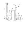
- FIG. 1 shows a circular knitting machine according to an embodiment of the present invention.
- the circular knitting machine 1 includes a plate-like base plate 2 fixed to a base.
- the base plate 2 has a fixing hole 3 fixed to the base on one end side, and an attachment hole 4 on the other end side.
- a hollow core rod 5 is fastened and fixed to the mounting hole 4 in a state in which the lower portion is prevented from loosening by two nuts 6 and 6.
- the core rod 5 protrudes from an upper end portion of an outer cylinder 7 to be described later, and functions as a rotation center axis of the outer cylinder 7.
- the core bar 5 has a function of guiding the string-like material knitted at the upper end portion downward through the hollow portion and a function of guiding a vertical movement of the knitted needle 8 described later.
- a size of 16 G is used for the knitted needle 8.
- the core rod 5 includes a male screw portion 9 in which nuts 6 and 6 are screwed to the outer periphery of the lower portion, and a bearing mounting portion 11 for mounting the inner peripheral side of the bearing 10 on the upper outer periphery of the male screw portion 9.
- Twelve guide grooves 12 for setting the knitted needle 8 in the circumferential direction are formed in the circumferential direction on the upper outer circumference in a range from the outer cylinder 7 to the upper end protruding from the outer cylinder 7.
- the diameter of the groove bottom 13 of the guide groove 12 is 8 mm, a diameter of 3 mm or more to less than 12 mm can be used according to the diameter of the string-like material to be knitted.
- a total of twelve knitted needles 8 are arranged in the guide groove 12.
- An inner race of the bearing 10 is fitted into the bearing mounting portion 11 of the core bar 5, and the bearing 10 is in a state where the end face is placed on the base plate 2.
- An outer cylinder 7 is rotatably mounted on the outer race of the bearing 10. Note that the rotation speed of the outer cylinder 7 is 3000 min ⁇ 1 , and it is required that the outer cylinder 7 is excellent without stitch skipping even after 100 hours of continuous operation.
- a large-diameter portion 14 having a larger diameter than the upper portion is formed in the lower portion of the outer cylinder 7.
- a belt groove 15 having a V-shaped cross section is formed on the outer periphery of the large-diameter portion 14, and a belt linked to a driving device (not shown) is stretched over the belt groove 15 to rotate the outer cylinder 7.
- the lower end surface of the large-diameter portion 14 slightly enters the spot facing portion 16 formed by cutting the upper surface of the base plate 2.
- the bearing 10 it is preferable to use a double-row angular type bearing so that the upper part does not shake even at high speed rotation.
- a toothed belt can be used instead of the belt V.
- a lower cam 17 and an upper cam 18 are respectively fixed to the inner peripheral surface of the outer cylinder 7 by a lower screw 19 and an upper screw 20 screwed from the outer peripheral surface of the outer cylinder 7.
- a fixed gap is secured as a groove width between the lower edge of the upper cam 18 and the upper edge of the lower cam 17, and a guide groove 21 having an inner peripheral surface of the outer cylinder 7 as a groove bottom is formed in an elliptical shape.
- the guide groove 21 receives a butt portion 22 projecting in the direction in which the latch 28 opens and closes near the lower portion of the knitted needle 8.
- the unfolded shape of the guide groove 21 is a mountain shape, and each outer needle 8 arranged around the core bar 5 moves up and down as the outer cylinder 7 rotates.
- the outer cylinder 7 is provided with a long hole 23, and the upper cam 18 is fixed with the upper screw 20 inserted through the long hole 23, and the upper screw 20 is loosened to form the lower tube 17. Further, the groove width (interval “H”) of the guide groove 21 can be adjusted.
- an end plate 24 having the same diameter as the outer cylinder 7 and forming a part of the outer cylinder 7 is attached to the outer cylinder 7 with a fixing screw 29.
- the end plate 24 includes a boss portion 30 that is inserted between the outer cylinder 7 and the core rod 5.
- the end plate 24 is provided with a stopper screw 25 that passes through the end plate 24 and positions the upper edge of the upper cam 18.
- the stopper screw 25 is provided with a lock screw 26 for fixing the position of the stopper screw 25.
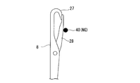
- the knitted needle 8 has a hook 27 at its upper end, and the hook 27 has a known structure that can be opened and closed by a latch 28. Twelve knitted needles 8 are arranged in the guide groove 12 with the hook 27 facing outward. These knitted needles 8 are sequentially raised and lowered along the guide groove 12 of the core bar 5 as the upper cam 18 and the lower cam 17 rotate together with the outer cylinder 7. Eleven knitted needles 8 protrude from the upper end surface of the core bar 5.
- a thread-shaped guide guide 31 having a rod-like and simple and light structure for guiding the yarn supplied to the knitted needle 8 is fixed by screwing a lower screw portion 32 therein.
- a yarn having a size of 420 dtex is used.
- a guide hole 34 is formed which is inserted with a yarn from a bobbin (not shown) and is constituted by another member.
- a lock nut 35 is provided on the screw portion 32. Further, it is desirable to use ceramic as a material of the guide hole 34 in order to suppress wear.
- the thread guide 31 also rotates together with the outer cylinder 7, the angle in the rotational direction to the knit needle 8 at the top dead center position with respect to the thread guide 31 does not change. While the yarn is fed from the yarn guide 31 that rotates together with the outer cylinder 7, the yarn is supplied so as to be wound around the knitted needle 8 protruding from the core rod 5, and is locked to the hook 27 of the knitted needle 8 that moves up and down sequentially. Thus, a new loop 37 is formed under the core bar 5.
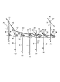
- FIG. 2 sequentially explains the state of the posture change in which the single knitting needle 8 moves up and down (schematic diagram showing the knitting operation by the circular knitting machine 1).
- the single movement of the knitted needle 8 is developed on a plane so that it can be easily explained.
- Reference numerals (1), (2), and (3) show the knitting needle 8 being lowered by the upper cam 18, and reference numerals (5), (6), and (7) are the knitting needle 8 by the lower cam 17. Shows the rise.
- Each knitted needle 8 is inserted with the previous loop 36 that constitutes the upper end of a string-like object (not shown).
- the posture (1) with the latch 28 opened, the knitted needle 8 starts to descend with the hook 27 engaging the thread 40.
- the knitted needle 8 is further lowered from the state in which the thread 40 is locked to the hook 27, and the posture is changed in the direction in which the latch 28 is closed by the previous loop 36.
- the latch 28 immediately before coming out of the previous loop 36 completely closes the hook 27, and the locked thread 40 does not come out of the hook 27 and continues to descend.
- the knitted needle 8 In the posture (4), the hook 27 is pulled out from the previous loop 36 and the thread 40 is pulled out.
- the knitted needle is now lifted to the outer peripheral side of the previous loop 36 in a state in which the knitting needle has left the previous loop 36.
- the thread 40 pulled out in the posture (5) becomes a new loop 37, and the new loop 37 starts to open the latch.
- the latch 28 of the knitted needle 8 which is further raised is opened by the new loop 37, and in the posture (7), the knitted needle 8 is locked to the thread 40 to which the hook 27 is next sent out with the latch 28 opened. To do. Thereafter, the knitted needle 8 is lowered to the posture (1).
- the latch 28 operates to jump up immediately after the latch 28 is released from the new loop 37.
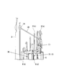
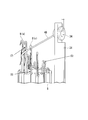
- FIGS. 3 and 4 are perspective views of the main part of the circular knitting machine as seen from different directions, and the loops already knitted are not shown for convenience of illustration.
- FIGS. 3 and 4 when an outer cylinder (not shown) rotates counterclockwise, the core rod 5 does not rotate and the thread guide guide rotates counterclockwise.
- the knitting needle 8 (a) that rises with the amount of protrusion gradually decreasing from the knitting needle 8 (a) at the top dead center to the knitting needle 8 (b) at the bottom dead center counterclockwise. Is located, and the protrusion amount gradually decreases from the knitted needle 8 (a) at the top dead center to the knitted needle 8 (b) at the bottom dead center in a clockwise direction. 8 is located.
- the thread 40 from the bobbin supplied from the guide hole 34 of the thread guide 31 has a second position in the counterclockwise direction from the knitted needle 8 (a) at the top dead center position.
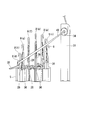
- FIG. 5 shows a passage path of the thread 40 that is arranged so as to be wound around the plurality of knitting needles 8.
- the thread 40 is the height of the base portion of the latch 28 and contacts the knitted needle 8.
- the previous loop 36 is just before coming out of the latch.
- the thread 40 is below the base portion of the latch 28 and is connected to the knitted needle 8. Passing through the contacted position, the previous loop 36 is immediately after the latch 28 is removed.
- the thread 40 passes through a position in contact with the vicinity of the central portion in the vertical direction of the latch 28, and the previous loop 36 is completely removed from the latch 28.
- the passing position of the thread 40 is specified at the position where the thread guide guide 31 is attached, the position within the rotation range of the latch 28 of the knitted needle 8 (e) immediately after the latch 28 is removed from the previous loop 36 during the ascending operation.
- the yarn guide guide 31 is attached to the outer cylinder 7 so that the guide hole 34 of the yarn guide guide 31 is located on the extended line of the path along the circumscribed surface of 8, 8, 8.
- the position through which the thread 40 passes is outside the knitted needle 8 arranged so that the thread 40 is wound as shown in FIG. 5, but the range through which the thread 40 passes is shown in FIG. Is set within the rotation range B at the base of the tip of the latch 28. That is, the yarn 40 supplied from the guide hole 34 of the yarn guide 31 is effectively used to form a new loop 37, and immediately after the latch 28 of the knitted needle 8 is removed from the previous loop 36 during the ascending operation. The latch 28 is prevented from jumping up.
- FIG. 8 is a view of the outer cylinder 7 and the core rod 5 as viewed from the upper side in the axial direction
- FIG. 9 is an enlarged view of a main part of FIG.
- the position of the guide hole 34 of the thread guide 31 in the circumferential direction of the outer cylinder 7 is counterclockwise (rotational direction) of the outer cylinder 7 from the position of the knitted needle 8 (a) at the top dead center position.
- the guide hole 34 of the yarn guide 31 is set in the range of angle ⁇ (45 ° to 100 °) toward the upper end of the hook 27 of the knitted needle 8 (a) at the top dead center position.
- the vertical dimension K is set within the range of 2 mm (2 mm upward) to ⁇ 4 mm (4 mm downward) from the hook 27.
- the distance L between the position of the guide hole 34 and the tangent to the core bar 5 on the line connecting the position of the guide hole 34 of the thread guide 31 and the axis of the core bar 5 is set to 5 mm to 8 mm. Yes. This value varies depending on the length of the latch 28.
- the range of the angle ⁇ is more preferably set to 45 degrees to 100 degrees.
- ⁇ 90 degrees
- K 2 mm
- the numerical range as described above is set because when the ⁇ is out of the above range, the yarn is out of the rotation range B of the latch 28 in FIG. If the angle ⁇ is outside the above range, the passing position of the yarn 40 immediately after exiting the yarn guide guide 31 is on the inner side of the diameter of the guide groove 12 of the core rod 5. When the thread 40 passes through the back surface of the knitted needle 8 that is raised downward, and then descends, the thread 40 cannot be locked to the hook 27.
- the thread 40 passes through a place higher than the knitted needle 8, and the hook 27 cannot be locked to the thread 40.
- the latch 28 shown in FIG. 6 deviates from the rotation range B, and the effect of preventing the latch 28 from jumping up cannot be exhibited.
- the diameter of the outer cylinder 7 increases, and the outer cylinder 7 expands, which is disadvantageous for high-speed rotation.
- the yarn guide The guide 31 itself contacts the latch 28.
- the latch 28 can be prevented from jumping up immediately after exiting the previous loop 36 using the yarns 40 that are sequentially supplied, so that the yarn guide guide 31 is provided with the yarn guide guide 31 to prevent the latch 28 from jumping up.
- the yarn guide 31 can be simplified and the outer cylinder 7 can be reduced in weight. Therefore, the rotation speed of the outer cylinder 7 can be increased (for example, 3000 to 4000 min ⁇ 1 ), the dynamic balance of the outer cylinder 7 is improved, and the string making speed depending on the rotation speed of the outer cylinder 7 is increased. Can also suppress the generation of vibrations and increase productivity.
- the knitting needle 8 that rises.
- the thread 40 can be arranged within the rotation range B of the latch 28 that jumps up immediately after the latch 28 has exited the previous loop 36. Therefore, the latch 28 can be reliably prevented from jumping up, and the yarn 40 that has exited the yarn guide guide 31 can be positioned so as to be surely wound around the outside of the knitted needle 8. Thus, the thread 40 can be reliably locked.
- the thread 40 can be securely attached to the descending knitting needle 8. Further, the thread 40 can be disposed in the rotation range B of the latch 28 that jumps immediately after the latch 28 of the rising knitted needle 8 exits the previous loop 36, so that the latch 28 Bounce-up can be surely prevented.
- this invention is not restricted to the said embodiment,
- the angular bearing was used as the bearing 10,
- positions a single row bearing up and down is also employable.
- the arrangement number, size, thread thickness, and the like of the knitted needle 8 are merely examples, and the present invention can also be applied to arrangement numbers, sizes, and thread thicknesses other than this embodiment.
- the core rod 5 is a cylindrical member having a hollow portion 5a through which the cylindrical braid A passes downward, and the upper end portion and the lower end portion are formed to have a slightly smaller diameter.
- a male threaded portion 9 in which nuts 6 and 6 are screwed onto the outer periphery of the lower end portion of the core bar 5 and a bearing mounting portion 11 for mounting the inner peripheral side of the bearing 10 on the upper outer periphery of the male threaded portion 9 are provided.
- Six guide grooves 12 for setting the knitted needle 8 in the circumferential direction are formed on the upper outer periphery of the bearing mounting portion 11 in the circumferential direction in a range from the outer cylinder 7 to the upper end portion protruding from the outer cylinder 7.
- the diameter d of the groove bottom 13 of the guide groove 12 (hereinafter referred to as the bottom circumferential diameter d) is set according to the outer diameter of the cylindrical braid A.
- the outer diameter of the cylindrical braid A is preferably in the range of 3 to 14 mm, more preferably 6 to 12 mm.
- the knitted needle 8 has a hook 27 at its upper end, and the hook 27 has a known structure that can be opened and closed by a latch 28.
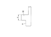
- a butt portion 22 is formed in the vicinity of the lower portion of the knitted needle 8 so as to protrude in the direction in which the latch 28 opens and closes.
- the knitted needle 8 is a thin plate material of about 0.5 mm, and the material is generally carbon tool steel, and the surface hardness after heat treatment is generally HRC 60 or more.
- the HRC measurement method is based on JIS Z 2245: 2005.
- the sizes of the hook 27 and the latch 28 are generally represented by a gauge “G”, and are appropriately selected depending on the fineness of the yarn 40 to be knitted. In this embodiment, 16G is preferable.
- the number of knitting needles 8 is preferably 5 to 16, more preferably 8 to 12, although it depends on the degree of opening of the knitted string A of the cylindrical knitted string A.
- the outer diameter of the cylindrical braid A obtained by combining the bottom circumferential diameter d of the core bar 5 and the number of the knitted needles 8 is about 3 to 8 mm.
- These knitted needles 8 are arranged in the guide groove 12 with the hooks 27 facing outward, and an upper cam 18 and a lower cam 17 (to be described later) rotate together with the outer cylinder 7 so that the butt portion 22 and the upper cam 18 are moved downward. It latches between the cams 17 and rises and descends in order along the guide grooves 12 of the core bar 5.
- a lower cam 17 and an upper cam 18 are respectively fixed to the inner peripheral surface of the outer cylinder 7.
- Both the lower cam 17 and the upper cam 18 are formed in a cylindrical shape, and the upper end of the lower cam 17 and the lower end of the upper cam 18 are inclined surfaces with a predetermined angle ⁇ with respect to the axis of the core rod 5.
- the upper cam 18 and the lower cam 17 face each other and are arranged vertically with the butt portion 22 of the knitted needle 8 interposed therebetween, and a vertical interval “slightly larger than the height“ h ”of the butt portion 22 shown in FIG.
- H ′′ is kept constant, and is fixed inside the cylinder of the outer cylinder 7 by a lower screw 19 and an upper screw 20 which are screwed from the outer peripheral surface of the outer cylinder 7.
- the inclined surface of the lower cam 17 is cut in the reverse direction on the upper end side
- the inclined surface of the upper cam 18 is cut in the reverse direction on the lower end side. Therefore, between the lower edge of the upper cam 18 and the upper edge of the lower cam 17, a guide groove 21 having an inner peripheral surface of the outer cylinder 7 as a groove bottom is formed in an elliptical shape. Part 22 is accepted.
- the outer cylinder 7 is provided with a long hole 23, and the upper cam 18 is fixed with the upper screw 20 inserted through the long hole 23, and the upper screw 20 is loosened to form the lower tube 17.
- the distance “H” between the guide grooves 21 can be adjusted.
- the angle ⁇ is determined by the bottom circumferential diameter d and the vertical movement stroke of the knitted needle 8. When the vertical movement stroke of the knitted needle 8 is the same, the angle ⁇ decreases and the inclined surface becomes steep when the bottom circumferential diameter d decreases. Conversely, as the bottom circumferential diameter d increases, the angle ⁇ increases and the inclined surface becomes gentler.
- an end plate 24 having the same diameter as the outer cylinder 7 and forming a part of the outer cylinder 7 is attached to the outer cylinder 7 with a fixing screw 29.
- the end plate 24 includes a boss portion 30 that is inserted between the outer cylinder 7 and the core rod 5.
- the end plate 24 is provided with a stopper screw 25 that passes through the end plate 24 and positions the upper edge of the upper cam 18.
- the stopper screw 25 is provided with a lock screw 26 for fixing the position of the stopper screw 25.
- the upper cam 18 and the lower cam 17 are rotated along with the rotation of the outer cylinder 7, and the butt portion 22 of the knitted needle 8 is raised along the cam crest 17 ⁇ / b> Y of the lower cam 17.
- the butt portion 22 of the knitted needle 8 that has reached the apex of the lower cam 17 is then lowered along the cam crest 18Y of the upper cam 18, so that the knitted needle 8 is lowered.
- the plurality of knitted needles 8 arranged on the circumference of the core bar 5 sequentially reciprocate.
- a tensioner (not shown) is provided upstream so as to apply a constant tension to the thread 40.
- tensile_strength etc. is provided.
- a rod-shaped, simple and light-weight thread guide 31 for guiding the thread 40 supplied to the knitting needle 8 is fixed by screwing a lower thread portion 32 therein.
- a guide hole 34 is provided which is inserted with a yarn 40 from a bobbin (not shown) and is constituted by another member.
- a lock nut 35 is provided on the screw portion 32.
- ceramic it is preferable to use ceramic as the material of the guide hole 34 in order to suppress wear with the yarn 40 moving at high speed. This is because if the yarn 40 is worn by friction, it may cause yarn breakage or yarn feathers.
- the thread guide 31 also rotates together with the outer cylinder 7, the angle in the rotational direction to the knit needle 8 at the top dead center position with respect to the thread guide 31 does not change.
- the yarn 40 is fed from the yarn guide 31 that rotates together with the outer cylinder 7, the yarn 40 is supplied so as to wrap around the knitted needle 8 protruding from the core bar 5, and is sequentially applied to the hook 27 of the knitted needle 8 that moves up and down.
- a new loop 37 is formed toward the bottom of the core bar 5 by being locked.
- the circular knitting performed by the circular knitting machine 1 is knitting a cylindrical horizontal knitted fabric.
- the horizontal knitted fabric is obtained by spirally forming a curved loop 37 and continuously connecting each loop 37 to the previous loop 36.
- a stitch 38 is provided in 36.
- the rotational speed of the outer cylinder 7 of the circular knitting machine 1 As the speed of knitting the cylindrical knitted string A (take-up speed) increases, the rotational speed of the outer cylinder 7 of the circular knitting machine 1 also increases accordingly.
- the rotational speed varies slightly depending on the number of the knitting needles 8, the bottom circumferential diameter d of the core bar 5, the size of the stitch 38, and the like, but when it is carried out within the preferred range of the present invention, the take-up speed is 1.7 m / At min, the rotational speed is about 1800-2200 min ⁇ 1 . Further, when the take-up speed is 3.4 m / min, the rotational speed is about 3000 to 3500 min ⁇ 1 . Further, when the take-up speed is 4.5 m / min, the rotation speed is about 4000 to 4500 min ⁇ 1 .
- the surface hardness of the cam crest 18Y and the cam crest 17Y greatly affects the wear.
- a cam with a cam peak surface hardness of HRC50 or less is used for continuous operation at a rotational speed of 3000 min -1 or more, significant wear occurs at the butt portion 22, cam peak 18 Y, and cam peak 17 Y after an operation time of 300 to 400 hours.
- the butt portion 22 breaks down, causing serious damage to the inside of the circular knitting machine 1 rotating at high speed.
- the surface hardness of the cam crest is preferably HRC51 or more, more preferably in the range of HRC55-60.
- the knitted needle 8, cam cam 18Y, and cam cam 17Y are hardly worn even during an operation time of 1000 hours, and sufficient durability is achieved. It turns out that there is sex.
- Examples of the method for bringing the surface hardness of the cam ridge into the above-described range include heat treatment such as quenching, or coating treatment such as DLC coating and TiN coating, and it is more preferable to perform the heat treatment.
- heat treatment such as quenching, or coating treatment such as DLC coating and TiN coating
- the material of the cam steel is used when heat treatment is performed, but carbon steel for machine structure, various tool steels, and the like can be used to obtain the above-described surface hardness.
- the material used for the coating treatment is not limited to steel, and various metals can be used.
- Examples of the heat treatment include carburizing and quenching, nitriding, induction hardening, and the like.
- the plurality of slit-shaped guide grooves 12 of the core rod 5 are likely to be worn by friction because the knitted needle 8 reciprocates.
- the knitted cylindrical knitted string A is pulled downward through the hollow portion 5a at the tip corner of the guide groove 12, so that the knitted needle 8 arranged on the circumference is loaded toward the center. Therefore, it is easy to wear. Therefore, it is preferable to improve the durability of the surface of the core bar 5 and the guide groove 12 by the same surface treatment as the cam crest 18Y and the cam crest 17Y. Also, the angle ⁇ shown in FIG. 13 affects the wear. When the angle ⁇ is small, that is, when the inclined surface is steep, the frictional resistance between the butt portion 22 and the cam crest 18Y and the cam crest 17Y increases, so that the wear easily proceeds. Therefore, the angle ⁇ is determined by the bottom circumferential diameter d and the vertical movement stroke of the knitted needle 8, but it is desirable to make it as large as possible.
- grease is used for lubrication, but the amount of grease applied and the consistency (consistency) indicating the hardness of the grease (corresponding to the kinematic viscosity of the lubricating oil) are also important for wear control.
- the grease present in the space 39 (see FIG. 1) formed between the outer cylinder 7 and the core rod 5.
- the grease becomes soft (viscosity decreases) due to heat generated by friction of the sliding portion.
- the grease becomes soft, it moves to the inner wall of the outer cylinder 7 due to the centrifugal force during high-speed operation as described above, and the sliding portions of the knitted needle 8, the upper cam 18, and the lower cam 17 are likely to be insufficiently lubricated. Progresses faster.
- the resistance of the grease imposes a load on each part of the knitting machine and the drive motor, thereby shortening the life of the apparatus. Accordingly, the hardness of the grease is also an important factor for suppressing wear.
- the hardness of the grease is represented by an NLGI (National Lubricating Grease Institute) consistency number described in JISK2220. The larger the number, the harder the grease.
- NLGI National Lubricating Grease Institute
- organic molybdenum grease containing solid lubricant molybdenum disulfide grease, fluorine-based grease, PTFE-containing grease, aluminum oxide, zinc oxide, ceramic grease containing ultrafine particles such as cubic boron nitride, etc. It is preferable to use it during high-speed operation because a low-friction lubricating coating is formed on the sliding surface to prevent metal contact and reduce wear and seizure.
- the wear of the parts constituting the circular knitting machine 1, particularly the upper cam 18, the lower cam 17 and the knitted needle 8, is suppressed as much as possible.
- the frequency of maintenance such as replacement of parts can be reduced, and the productivity of the cylindrical braided string A can be increased.
- the cam crest 18Y and the cam crest 17Y of the upper cam 18 and the lower cam 17 are hardened, the cost can be reduced as compared with the case where the hardness of the entire upper cam 18 and the lower cam 17 is increased. it can.
- the amount of wear of the butt portion 22 of the knitted needle 8 is determined by removing the knitted needle 8 from the circular knitting machine 1 after operation, and observing the butt portion 22 with a stereomicroscope, as shown in FIG.
- the amount of wear h2 was measured with a scale (ruler).
- Example 1 A cylindrical knitted string A was produced using the circular knitting machine 1 shown in FIG.
- a polyester fiber fineness: 420 dtex, number of filaments: 180
- a table-type string knitting machine manufactured by Sakurai Textile Machinery Co., Ltd., the number of knitting needles: 12, knitting needle size: 16G, the bottom circumferential diameter d of the core bar: 8 mm, cam hardness: HRC55
- lubricant Sumitomo Lubricant Co., Ltd. organic molybdenum grease (trade name: Mori FM-L grease (No.
- the space portion 39 (see FIG. 1) where the sliding portions of the upper cam 18 and the lower cam 17 are provided is sufficiently filled and sealed.
- the take-up speed of the take-up machine was 1.94 m / min. At this time, the rotational speed of the circular knitting machine 1 was about 2000 min ⁇ 1 .
- the operation time was about 100 hours. Immediately after the stop, the operation was continued using the new yarn 40, and a continuous operation was performed for a total of 3000 hours.
- the average value of the wear amount of the upper wear amount h1 and the lower wear amount h2 was about 0.35 mm. It was about 12% of the height h. Further, when the cam crest 18Y and the cam crest 17Y that are the sliding portions of the upper cam 18 and the lower cam 17 with the knitted needle 8 were observed, no wear was confirmed.
- Example 2 A cylindrical knitted string A was produced under the same conditions as in Example 1 except that the take-up speed of the take-up machine was 3.4 m / min. At this time, the rotational speed of the circular knitting machine 1 was about 3500 min ⁇ 1 . When the operation was continued until the yarn 40 wound around the supply bobbin disappeared, the operation time was about 50 hours. Immediately after the stop, the operation was continued using the new yarn 40, and a continuous operation was performed for a total of 500 hours. When the bat portion 22 of all the knitted needles 8 was observed with a stereomicroscope after the operation was completed, the average value of the wear amount of the upper wear amount h1 and the lower wear amount h2 was about 0.41 mm. It was about 14% of the height h. Further, when the cam crest 18Y and the cam crest 17Y that are the sliding portions of the upper cam 18 and the lower cam 17 with the knitted needle 6 were observed, no wear was confirmed.
- Example 3 A cylindrical knitted string A was produced under the same conditions as in Example 1 except that the take-up speed of the take-up machine was 4.5 m / min. At this time, the rotational speed of the circular knitting machine 1 was about 4500 min ⁇ 1 . When continuously operating until the yarn 40 wound around the supply bobbin disappeared, the operation time was about 38 hours. Immediately after the stop, the operation was continued using the new yarn 40, and a continuous operation was performed for a total of 265 hours. When the butt portion 22 of all the knitted needles 8 was observed with a stereomicroscope after the operation was completed, the average value of the wear amount of the upper wear amount h1 and the lower wear amount h2 was about 0.46 mm. It was about 15% of the height h. Further, when the cam crest 18Y and the cam crest 17Y that are the sliding portions of the upper cam 18 and the lower cam 17 with the knitted needle 6 were observed, no wear was confirmed.
- Example 1 A cylindrical knitted string A was produced under the same conditions as in Example 1 except that the filling amount of the lubricant was about 1/5 of that in Example 1. At this time, the rotational speed of the circular knitting machine 1 was about 2000 min ⁇ 1 . When the operation time was about 320 hours, the noise was generated from the circular knitting machine 1, so the operation was stopped. When the butt portion 22 of all the knitted needles 8 was observed with a stereomicroscope, the average value of the wear amount of the upper wear amount h1 and the lower wear amount h2 was about 1.5 mm, and the height h of the butt portion 22 was About 50%.
- the circular knitting machine of the present invention can effectively prevent latch jumping, it can be suitably used, for example, for manufacturing string-like objects.
Landscapes
- Engineering & Computer Science (AREA)
- Textile Engineering (AREA)
- Knitting Machines (AREA)
Abstract
Description
メリヤス針には、下降動作の際に係止した糸が抜けないように開閉するラッチが設けられている。このラッチはメリヤス針が上昇する際には、次の糸を係止するために開いている必要があるため、メリヤス針が上昇する際にラッチが閉じるのを防止するラッチ押さえを備えた丸編機がある(特許文献2参照)。
編目の数の上限は、円筒状編紐の外径、糸の繊度、編目の大きさ(ループの大きさ)等により決まる。編目が大きい場合、製膜原液を編紐支持体に塗布する際に、製膜原液が編紐支持体の内部に流入して中空部が閉塞するおそれがある。したがって、同じ外径の円筒状編紐を製造する場合、糸の繊度が高いと編目の数は少なく、繊度が低いと編目の数は多く設定する必要がある。
また、外筒の回転に伴いラッチがラッチ押さえに多回数当たるため、メリヤス針の耐久性が低下する課題がある。
また、カム側の磨耗は抑制できても、逆に硬度の低い編み針バット部側の磨耗が早くなると推測でき、編み針の交換頻度が多くなり、生産性低下に繋がると考えられる。
そこで、この発明は、丸編機の回転速度を上げてもカムが丸編機を構成する部品類の磨耗を抑制し、円筒状編紐を生産性良く製造できる中空状多孔質膜用支持体に用いる円筒状編紐を編成する丸編機をも提供する。
前記メリヤス針のラッチが前回編成したループからラッチが抜けた直後のメリヤス針の前記ラッチの回動範囲内に前記糸が配索する位置に前記ガイドを配設した編機である。
前記ガイドとメリヤス針のフックが前記糸を係止する位置との間に前記糸によるラッチ押え部(ラッチ跳ね返り防止部又はラッチ跳ね上げ防止機構ともいう)を有する編機である。
上昇動作中にラッチがループから抜けた直後の前記メリヤス針の前記ラッチの回動範囲(例えば、実施形態における回動範囲B)内と、下降動作にありフックに次の糸が係止しようとしているメリヤス針のフックの係止位置(係止範囲)(例えば、実施形態における係止範囲C)との間を結ぶメリヤス針の外接面に沿う経路の延長線上にガイド孔が位置するように前記糸案内ガイドを外筒に設けた編機である。
このように構成することで、メリヤス針に供給される糸自身を有効利用し、メリヤス針の上昇動作中にラッチがループから抜けた直後に跳ね上がるラッチの動きを規制してラッチがフックを閉じないようにすることができる。
このように構成することで、メリヤス針に供給される糸自身を有効利用し、メリヤス針の上昇動作中にラッチがループから抜けた直後に跳ね上がるラッチの動きを規制してラッチがフックを閉じないようにすることができる。
糸案内ガイドのガイド孔の位置を、前述した寸法の範囲に設定することにより、下降するメリヤス針に糸を確実に係止することができ、上昇するメリヤス針のラッチがループを抜けた直後に跳ね上がるラッチの回動範囲内に糸を配置することができるので、ラッチの跳ね上げを確実に防止することができる。
外筒7の下部には、それよりも上の部分に比較して直径が大きい大径部14が形成されている。大径部14の外周には断面V字状のベルト溝15が形成され、このベルト溝15に図示しない駆動装置に連係されたベルトを掛け渡して外筒7を回転駆動させる。ここで、大径部14の下端面はベース板2の上面を切除して形成された座グリ部16にやや入り込むようになっている。
ここで、糸案内ガイド31も外筒7と共に回転するので、糸案内ガイド31に対して上死点位置にあるメリヤス針8までの回転方向での角度は変化しない。
外筒7と共に回転する糸案内ガイド31から糸が送り出されながら、芯棒5から突出しているメリヤス針8に糸が巻き付くように供給され、順次上下動するメリヤス針8のフック27に係止して新しいループ37が芯棒5の下に向かって形成されてゆく。
各メリヤス針8には紐状物(図示略)の上端部を構成する前回のループ36が挿通されている。姿勢(1)では、ラッチ28が開いた状態でメリヤス針8はフック27が糸40を係止して下降を始める。姿勢(2)では、メリヤス針8はフック27に糸40を係止した状態から更に下降し、前回のループ36によってラッチ28が閉じる方向に姿勢変化する。姿勢(3)では、前回のループ36から抜け出る直前のラッチ28がフック27を完全に閉じ、係止した糸40がフック27から抜け出ない状態となり下降を続ける。
符号(1)において、糸40をフック27に引っ掛ける。符号(2)、(3)において、糸40を引き下げながら、以前に編成された既存ループ36を通過することによりラッチ28が閉じられ、フック27が既存ループ36に引っ掛らないようになっている。符号(4)において既存ループ36からメリヤス針8が下方に抜ける。次に、符号(5)、(6)に示すように、メリヤス針8が上昇すると、新たに形成されつつあるループ37の糸40によりラッチ28が開放され、符号(7)において、新たなループ37が形成される。以上の作用を繰り返すことにより連続的に丸編みを行い、円筒状編紐Aを編成する。
編成した円筒状編紐Aは、芯棒5の中空部5a(図1、図2参照)を通過して丸編機1の下方に排出され、図示しない引取り機によって引き取られる。
上死点のメリヤス針8(a)から反時計回りで2番目の位置にある上昇するメリヤス針8(c)では、糸40はラッチ28の付け根部分の高さであってメリヤス針8に接触しない位置を通過し、前回のループ36はラッチから抜ける直前にある。
上死点のメリヤス針8(a)から反時計回りで1番目の位置にある上昇するメリヤス針8(e)では、糸40はラッチ28の付け根部分よりも下側であってメリヤス針8に接触した位置を通過し、前回のループ36はラッチ28から抜けた直後となる。
上死点のメリヤス針8(a)では、糸40はラッチ28の上下方向中央部付近に接触した位置を通過し、前回のループ36は完全にラッチ28から抜けている。
上死点のメリヤス針8(a)から時計回りで2番目の位置にある下降するメリヤス針8(g)では、糸40はラッチ28の上下方向中央部付近に接触した位置を通過し、前回のループ36にラッチ28が到達している。
上死点のメリヤス針8(a)から時計回りで3番目の位置にある下降するメリヤス針8(h)では、糸40はラッチ28の付け根部分よりも上に接触した位置を通過し、前回のループ36によってラッチ28がフック27を閉じる方向に回動している。
上死点のメリヤス針8(a)から時計回りで4番目の位置にある下降するメリヤス針8(d)では、糸40はラッチ28のフック27に係止した状態となり、前回のループ36によってラッチ28がフック27を完全に閉じている。
図8において、糸案内ガイド31のガイド孔34の位置が、外筒7の周方向では、上死点位置にあるメリヤス針8(a)の位置から外筒7の反時計回り(回転方向)に向かって角度θ(45度~100度)の範囲に設定され、糸案内ガイド31のガイド孔34の位置が、上死点位置にあるメリヤス針8(a)のフック27の上端部を基準とした上下方向の寸法Kがフック27から2mm(上方に2mm)~-4mm(下方に4mm)の範囲内に設定されている。また、糸案内ガイド31のガイド孔34の位置と芯棒5の軸心とを結ぶ線上で、ガイド孔34の位置と芯棒5の接線との間の距離Lは5mm~8mmに設定されている。尚、この値はラッチ28の長さにより変動する値である。
このように設定することで、特に前回のループ36から抜け出したラッチ28の跳ね上がりを糸40自身により阻止して確実に次の糸40をメリヤス針8により係止することを可能としている。
そして、距離Lが上記範囲を大きい方に外れると、外筒7の直径が大きくなり、外筒7が拡大して高速回転に不利となり、距離Lが上記範囲を小さい方に外れると、糸案内ガイド31そのものがラッチ28に接触してしまう。
また、ラッチ28の跳ね上げを防止する糸40は順次新しいものが供給されるため、糸40に与える損傷もなくメリヤス針8が損傷することもなくなる。また、ラッチ28の跳ね上げ防止のための別部材が必要なく、この別部材を設けた場合に比較してラッチ28の破損によるメンテナンスの必要もなくなりその点でも生産性を高めることができる。
糸案内ガイド31のガイド孔34の位置を、上死点位置にあるメリヤス針8(a)のフック27の上下方向の寸法の範囲に設定することにより、下降するメリヤス針8に糸40を確実に係止することができ、更に上昇するメリヤス針8のラッチ28が前回のループ36を抜けた直後に跳ね上がるラッチ28の回動範囲B内に糸40を配置することができるので、ラッチ28の跳ね上げを確実に防止することができる。
フック27、ラッチ28の大きさは一般的にゲージ“G”で表され、編成する糸40の繊度により適宜選択される。この実施形態では16Gが好適である。また、メリヤス針8の本数は円筒状編紐Aの編み目の開き具合にもよるが5~16本が好ましく、8~12本がより好ましい。この実施形態では図2に示す芯棒5の案内溝12の数である6本の場合で説明している。そして、この場合に芯棒5の底部円周直径d及びメリヤス針8の本数の組合せにより得られる円筒状編紐Aの外径は、約3~8mmである。
これらメリヤス針8は、フック27が外側に向いた状態で案内溝12に配置され、後述する上カム18と下カム17が外筒7と共に回転することにより、バット部22が上カム18と下カム17との間に係止して芯棒5の案内溝12に沿って順番に上昇して下降する。
よって、上カム18の下縁と下カム17の上縁との間には、外筒7の内周面を溝底とするガイド溝21が楕円形状に形成され、ここにメリヤス針8のバット部22を受け入れている。ここで、外筒7には長孔23が設けられ、この長孔23に挿通された上ねじ20で上カム18を固定し、上ねじ20を緩めることにより下カム17との間に形成されたガイド溝21の間隔“H”の調整を行うことができる。
また、角度αは、底部円周直径d及びメリヤス針8の上下動ストロークによって決まる。メリヤス針8の上下動ストロークが同じ場合、底部円周直径dが小さくなると角度αは小さくなり、傾斜面は急勾配となる。逆に、底部円周直径dが大きくなるほど角度αは大きくなり、傾斜面は緩やかになる。
尚、供給される糸40が緩むとメリヤス針8のフック27から糸40が外れてメリヤス針8に絡むトラブルとなるため、糸40には一定の張力を付与するように上流側に図示しないテンサー等の張力を付与する部材が設けられている。
ここで、糸案内ガイド31も外筒7と共に回転するので、糸案内ガイド31に対して上死点位置にあるメリヤス針8までの回転方向での角度は変化しない。
外筒7と共に回転する糸案内ガイド31から糸40が送り出されながら、芯棒5から突出しているメリヤス針8に糸40が巻き付くように供給され、順次上下動するメリヤス針8のフック27に係止して新しいループ37が芯棒5の下に向かって形成されてゆく。
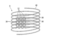
丸編機1により行われる丸編みとは、円筒状の横メリヤス生地を編成することである。
図14に示すように、横メリヤス生地は、湾曲したループ37連続的に形成した糸40を螺旋状にして、各ループ37を前回のループ36に上下につなげたものであり、ループ37やループ36内に編目38を有する。
カムの材質は、熱処理を施す場合には鋼材を用いるが、前述の表面硬度を得るには、機械構造用炭素鋼や各種工具鋼などを用いることができる。コーティング処理を施す場合の材質は鋼材に限定されず、各種金属を用いることが可能である。熱処理としては、浸炭焼入れ処理、窒化処理、高周波焼入れ等による処理が挙げられる。
また、芯棒5の複数のスリット状の案内溝12も同様にメリヤス針8が往復運動するため摩擦による磨耗が発生しやすい。特に、案内溝12の先端角部は、編成した円筒状編紐Aが中空部5aを通って下部に引っ張られるため、円周上に配置されたメリヤス針8は中心方向に向かって荷重が掛かかるため、磨耗しやすい。
したがって、芯棒5の表面及び案内溝12もカム山18Y、カム山17Yと同様の表面処理を施すことが耐久性向上には好ましい。
また、図13に示す角度αも磨耗に影響を及ぼす。角度αが小さい、すなわち傾斜面が急勾配になると、バット部22とカム山18Y、カム山17Yの摩擦抵抗が増えるため、磨耗が進行しやすくなる。従って、角度αは、底部円周直径d及びメリヤス針8の上下動ストロークで決まるが、出来る限り大きくすることが望ましい。
特に、メリヤス針8と上カム18、下カム17の摺動部に塗布するグリスが少量の場合、外筒7と芯棒5との間にできる空間部39(図1参照)に存在するグリスは、高速運転時の遠心力により、外筒7の内壁に移動して、メリヤス針8と上カム18、下カム17の摺動部の潤滑が不十分となりやすく、磨耗の進行が早まる。これに対して、グリスが空間部39を埋めるように十分に封入した場合、高速運転時においても遠心力でグリスが外筒7の内壁移動しにくくなり、メリヤス針8と上カム18、下カム17の摺動部には十分な潤滑が得られ、メリヤス針8のバット部22とカム山18Y、カム山17Yの磨耗を抑制することができる。
また、グリスは摺動部の摩擦による発熱で柔らかくなる(粘度が低下する)。グリスが柔らかくなると、前述の如く高速運転時の遠心力により、外筒7の内壁に移動して、メリヤス針8と上カム18、下カム17の摺動部の潤滑が不十分となりやすく、磨耗の進行が早まる。しかし、ちょう度が大きい硬いグリスを用いるとグリスの抵抗により編機の各部及び駆動モーターに負荷がかかり装置の寿命を縮める。従って、グリスの硬さも磨耗抑制には重要な要素となる。
グリスの硬さは、JISK2220に記載のNLGI(国際グリース協会、National Luburicatiing Grease Institute)ちょう度番号で表され、番号の数字が大きいほど硬いグリスとなる。本発明のグリスには、NLGIのちょう度番号「1号」~「2号」の範囲のグリスを用いることが好ましく、混和ちょう度範囲が265~295(1/10/mm)であるNLGIのちょう度番号「2号」のグリスを用いることがより好ましい。
また、上カム18と下カム17のカム山18Y、カム山17Yが表面硬化しているため、上カム18と下カム17全体の硬度を上げた場合に比較して低コスト化を図ることができる。
(編針磨耗量の測定)
メリヤス針8のバット部22の磨耗量は、運転後、丸編機1からメリヤス針8を抜取り、バット部22を実体顕微鏡にて観察し、図12Bに示す如く、上側磨耗量h1及び下側磨耗量h2をスケール(定規)により測定した。
図1に示す丸編機1を用いて、円筒状編紐Aを製造した。
糸40としては、ポリエステル繊維(繊度:420dtex、フィラメント数:180)を用いた。丸編機1としては、卓上型紐編機(圓井繊維機械社製、編針数:12本、メリヤス針サイズ:16G、芯棒の底部円周直径d:8mm、カム硬度:HRC55)を用いた。潤滑剤には、住鉱潤滑剤(株)の有機モリブデングリス(商品名:モリFM-Lグリス(ちょう度番号2号))を外筒7の内部にある、メリヤス針8、芯棒5、上カム18、下カム17の各摺動部のある空間部39(図1参照)に十分に充填封入した。引取り機の引取り速度を1.94m/minとした。このときの丸編機1の回転速度は約2000min-1であった。供給用ボビンに巻かれた糸40が無くなるまでの連続で運転したところ、運転時間は約100時間であった。停止後すぐに新しい糸40を用いて運転を継続し、延べ3000時間の連続運転を実施した。
引取り機の引取り速度を3.4m/minとした以外は、実施例1と同じ条件で円筒状編紐Aを製造した。
このときの丸編機1の回転速度は約3500min-1であった。供給用ボビンに巻かれた糸40が無くなるまでの連続で運転したところ、運転時間は約50時間であった。停止後すぐに新しい糸40を用いて運転を継続し、延べ500時間の連続運転を実施した。
運転終了後、メリヤス針8全てのバット部22を実体顕微鏡で観察したところ、上側磨耗量h1と下側磨耗量h2の磨耗量を合わせた平均値は約0.41mmであり、バット部22の高さhの約14%であった。また、上カム18及び下カム17のメリヤス針6との摺動部となるカム山18Y、カム山17Yを観察したところ、磨耗は確認されなかった。
引取り機の引取り速度を4.5m/minとした以外は、実施例1と同じ条件で円筒状編紐Aを製造した。
このときの丸編機1の回転速度は約4500min-1であった。供給用ボビンに巻かれた糸40が無くなるまでの連続で運転したところ、運転時間は約38時間であった。停止後すぐに新しい糸40を用いて運転を継続し、延べ265時間の連続運転を実施した。
運転終了後、メリヤス針8全てのバット部22を実体顕微鏡で観察したところ、上側磨耗量h1と下側磨耗量h2の磨耗量を合わせた平均値は約0.46mmであり、バット部22の高さhの約15%であった。また、上カム18及び下カム17のメリヤス針6との摺動部となるカム山18Y、カム山17Yを観察したところ、磨耗は確認されなかった。
潤滑剤の充填量を実施例1の約1/5とした以外は、実施例1と同じ条件で円筒状編紐Aを製造した。
このときの丸編機1の回転速度は約2000min-1であった。述べ運転時間が約320時間となったとき、丸編機1から異音が発生したため、運転を中止した。
メリヤス針8全てのバット部22を実体顕微鏡で観察したところ、上側磨耗量h1と下側磨耗量h2の磨耗量を合わせた平均値は約1.5mmであり、バット部22の高さhの約50%であった。
潤滑剤に一般的なリチウムグリス(ちょう度番号2号)を用いた以外は、実施例2と同じ条件で円筒状編紐Aを製造した。
このときの丸編機1の回転速度は約3500min-1であった。供給用ボビンに巻かれた糸40が無くなるまでの連続で運転したところ、運転時間は約50時間であった。停止後すぐに新しい糸40を用いて運転を継続し、延べ500時間の連続運転を実施した。
運転終了後、メリヤス針8全てのバット部22を実体顕微鏡で観察したところ、上側磨耗量h1と下側磨耗量h2の磨耗量を合わせた平均値は約1.4mmであり、バット部22の高さhの約45%であった。
5 芯棒
7 外筒
8 メリヤス針
12 案内溝
18 上カム
17 下カム
18Y カム山
17Y カム山
28 ラッチ
27 フック
39 空間部
40 糸
36 ループ
34 ガイド孔
d 底部円周直径
A 円筒状編紐
B 回動範囲
Claims (11)
- 中空の芯棒の周方向に配置された、ラッチを有する複数のメリヤス針が、芯棒の軸方向に沿って往復運動可能に支持され、前記メリヤス針に供給する糸を案内するガイドが前記芯棒を中心軸として回転するように設けられた編機であって、
前記メリヤス針のラッチが前回編成したループからラッチが抜けた直後のメリヤス針の前記ラッチの回動範囲内に前記糸が配索する位置に前記ガイドを配設した編機。 - 中空の芯棒の周方向に配置された複数のメリヤス針が芯棒の軸方向に沿って往復運動可能に支持され、前記メリヤス針に供給する糸を案内するガイドが前記芯棒を中心軸として回転するように設けた編機であって、
前記ガイドとメリヤス針のフックが前記糸を係止する位置との間に前記糸によるラッチ押え部を有する編機。 - 芯棒に外筒が回転可能に支持され、前記芯棒に対して周方向に配置された複数のメリヤス針が芯棒の軸方向に沿って上下動可能に支持され、前記外筒の端部から突出して上下動する前記メリヤス針に供給される糸を案内する糸案内ガイドが設けられた紐状物の丸編機であって、
上昇動作中にラッチがループから抜けた直後の前記メリヤス針の前記ラッチの回動範囲内と、下降動作にありフックに次の糸が係止しようとしているメリヤス針のフックの係止位置との間を結ぶメリヤス針の外接面に沿う経路の延長線上にガイド孔が位置するように前記糸案内ガイドを外筒に設けた編機。 - 前記ガイドの位置が、前記芯棒の周方向では、上死点位置にある前記メリヤス針の位置から前記ガイドの回転方向に向かって45度~100度の範囲に設定され、かつ上死点位置にある前記メリヤス針の前記フックの上下方向では、前記フックから上方に2mm、下方に4mmの範囲内に設定されている請求項3に記載の編機。
- 前記メリヤス針の本数が5~16本の範囲である請求項1~4の何れか一項に記載の編機。
- 前記案内溝の底部円周直径が3~14mmの範囲である請求項5に記載の編機。
- 編成される編物の外径が3~8mmの範囲である請求項6に記載の編機。
- 中空状多孔質膜用支持体に用いる円筒状編紐を編成する請求項7に記載の編機。
- 前記外筒の回転速度が1800~4500min-1の範囲に設定された、請求項8に記載の編機。
- 前記芯棒の外周面長手方向に前記メリヤス針が芯棒の軸方向に沿って上下動可能に支持するための複数の案内溝を備え、前記外筒の内部には前記メリヤス針に上下動を付与する二つの円筒状のカムが配置され、前記カムと前記メリヤス針が当接するカム山の摺動部を含む前記外筒内の空間部及び前記各案内溝とに、固形潤滑剤を含んだグリスが充填封入されている請求項3~9の何れか一項に記載の編機。
- 前記固形潤滑剤が有機モリブデン、二硫化モリブデン、PTFE、酸化アルミ、酸化亜鉛、及び立方晶窒化ホウ素からなる群より選択される請求項10記載の編機。
Priority Applications (3)
| Application Number | Priority Date | Filing Date | Title |
|---|---|---|---|
| CN201290000634.1U CN203977057U (zh) | 2011-04-26 | 2012-04-26 | 具有针舌弹起防止机构的绳状物的圆编编织机 |
| KR2020137000074U KR200478544Y1 (ko) | 2011-04-26 | 2012-04-26 | 래치 튀어오름 방지 기구를 구비한 끈 형상물의 편기 |
| JP2012524422A JP6003644B2 (ja) | 2011-04-26 | 2012-04-26 | ラッチ跳ね上げ防止機構を備えた紐状物の丸編機 |
Applications Claiming Priority (6)
| Application Number | Priority Date | Filing Date | Title |
|---|---|---|---|
| JP2011-098202 | 2011-04-26 | ||
| JP2011098202 | 2011-04-26 | ||
| JP2011-185157 | 2011-08-26 | ||
| JP2011185157 | 2011-08-26 | ||
| JP2011-193803 | 2011-09-06 | ||
| JP2011193803 | 2011-09-06 |
Publications (1)
| Publication Number | Publication Date |
|---|---|
| WO2012147851A1 true WO2012147851A1 (ja) | 2012-11-01 |
Family
ID=47072366
Family Applications (1)
| Application Number | Title | Priority Date | Filing Date |
|---|---|---|---|
| PCT/JP2012/061208 Ceased WO2012147851A1 (ja) | 2011-04-26 | 2012-04-26 | ラッチ跳ね上げ防止機構を備えた紐状物の丸編機 |
Country Status (4)
| Country | Link |
|---|---|
| JP (1) | JP6003644B2 (ja) |
| KR (1) | KR200478544Y1 (ja) |
| CN (1) | CN203977057U (ja) |
| WO (1) | WO2012147851A1 (ja) |
Cited By (1)
| Publication number | Priority date | Publication date | Assignee | Title |
|---|---|---|---|---|
| CN111893635A (zh) * | 2020-08-31 | 2020-11-06 | 东莞市利美包装材料有限公司 | 一种耳线编织机头及编织机构 |
Families Citing this family (5)
| Publication number | Priority date | Publication date | Assignee | Title |
|---|---|---|---|---|
| CN110004581A (zh) * | 2019-04-26 | 2019-07-12 | 浙江海伦塑胶有限公司 | 针织单元和含有针织单元的针通机及其生产工艺和产品 |
| KR102287747B1 (ko) * | 2020-05-15 | 2021-08-06 | 정주옥 | 끈 제조용 스핀들 뭉치 |
| KR102324381B1 (ko) * | 2020-08-10 | 2021-11-09 | 정주옥 | 끈 제조용 스핀들 뭉치 |
| KR102227389B1 (ko) | 2020-09-04 | 2021-03-12 | 최세흠 | 녹방지가 완벽하고 내구적인 끈 제조용 편직기 |
| KR102287746B1 (ko) * | 2020-11-20 | 2021-08-06 | 정주옥 | 스핀들 뭉치용 니들스핀들 |
Citations (6)
| Publication number | Priority date | Publication date | Assignee | Title |
|---|---|---|---|---|
| US3257828A (en) * | 1963-10-01 | 1966-06-28 | Singer Co | Multi-feed knitting machine for reinforcing flexible hose or the like |
| JPS571891U (ja) * | 1980-06-04 | 1982-01-07 | ||
| JPS60193993U (ja) * | 1984-06-04 | 1985-12-24 | 植村株式会社 | リリヤン編機 |
| JPS6112791A (ja) * | 1984-06-28 | 1986-01-21 | Yuka Meramin Kk | 固体潤滑剤含有グリ−ス |
| JPH0266691U (ja) * | 1988-11-09 | 1990-05-21 | ||
| JP2008114180A (ja) * | 2006-11-07 | 2008-05-22 | Mitsubishi Rayon Co Ltd | 中空状多孔質膜用支持体、中空状多孔質膜およびそれらの製造方法 |
-
2012
- 2012-04-26 JP JP2012524422A patent/JP6003644B2/ja active Active
- 2012-04-26 WO PCT/JP2012/061208 patent/WO2012147851A1/ja not_active Ceased
- 2012-04-26 KR KR2020137000074U patent/KR200478544Y1/ko not_active Expired - Lifetime
- 2012-04-26 CN CN201290000634.1U patent/CN203977057U/zh not_active Expired - Lifetime
Patent Citations (6)
| Publication number | Priority date | Publication date | Assignee | Title |
|---|---|---|---|---|
| US3257828A (en) * | 1963-10-01 | 1966-06-28 | Singer Co | Multi-feed knitting machine for reinforcing flexible hose or the like |
| JPS571891U (ja) * | 1980-06-04 | 1982-01-07 | ||
| JPS60193993U (ja) * | 1984-06-04 | 1985-12-24 | 植村株式会社 | リリヤン編機 |
| JPS6112791A (ja) * | 1984-06-28 | 1986-01-21 | Yuka Meramin Kk | 固体潤滑剤含有グリ−ス |
| JPH0266691U (ja) * | 1988-11-09 | 1990-05-21 | ||
| JP2008114180A (ja) * | 2006-11-07 | 2008-05-22 | Mitsubishi Rayon Co Ltd | 中空状多孔質膜用支持体、中空状多孔質膜およびそれらの製造方法 |
Cited By (2)
| Publication number | Priority date | Publication date | Assignee | Title |
|---|---|---|---|---|
| CN111893635A (zh) * | 2020-08-31 | 2020-11-06 | 东莞市利美包装材料有限公司 | 一种耳线编织机头及编织机构 |
| CN111893635B (zh) * | 2020-08-31 | 2023-10-31 | 东莞市利美包装材料有限公司 | 一种耳线编织机头及编织机构 |
Also Published As
| Publication number | Publication date |
|---|---|
| KR200478544Y1 (ko) | 2015-10-16 |
| KR20140000376U (ko) | 2014-01-16 |
| JP6003644B2 (ja) | 2016-10-05 |
| JPWO2012147851A1 (ja) | 2014-07-28 |
| CN203977057U (zh) | 2014-12-03 |
Similar Documents
| Publication | Publication Date | Title |
|---|---|---|
| JP6003644B2 (ja) | ラッチ跳ね上げ防止機構を備えた紐状物の丸編機 | |
| CN101040069B (zh) | 用于制造单丝状产品的方法 | |
| JP5711062B2 (ja) | 紡糸巻取機 | |
| Lau et al. | Knittability of high-modulus yarns | |
| KR101427597B1 (ko) | 브레이딩 머신용 캐리어 | |
| TW201901059A (zh) | 齒型皮帶傳動裝置 | |
| JP2010148481A (ja) | 組紐 | |
| JP2001303358A (ja) | 耐摩耗性に優れた高性能釣糸 | |
| KR101307440B1 (ko) | 형태 안정성이 우수한 코드사의 제조 방법 | |
| JP6210209B2 (ja) | モノフィラメント様高強度ポリエチレン繊維 | |
| JP2014231668A (ja) | 組紐 | |
| JP2014526618A (ja) | 精紡機または撚糸機に用いる糸案内リング | |
| US3738125A (en) | Three-strand knitted yarn | |
| JP2006089154A (ja) | 繊維束の綾振り装置、巻取装置および繊維束パッケージの製造装置 | |
| JP7162459B2 (ja) | リング式紡機のリング/トラベラ系 | |
| CN216427824U (zh) | 一种钢丝绳复合结构绳芯 | |
| KR102347380B1 (ko) | 경량의 끈 제조용 편직기 | |
| US20230234807A1 (en) | System for Producing Yarn | |
| JP2015232189A (ja) | 編機及び編機を用いた紐状物の製造方法 | |
| CZ20003808A3 (cs) | Otočný chapač ąicího stroje | |
| KR102313156B1 (ko) | 마스크 끈용 튜블러 편기의 헤드 | |
| KR101931761B1 (ko) | 보빈케이스베이스가 구비된 매듭형 밑실공급장치 | |
| CN213596501U (zh) | 一种纤维退丝装置 | |
| JP2016121418A (ja) | シンカー使用の編成方法および編機 | |
| CN209009833U (zh) | 一种涤纶丝绕线装置 |
Legal Events
| Date | Code | Title | Description |
|---|---|---|---|
| WWE | Wipo information: entry into national phase |
Ref document number: 201290000634.1 Country of ref document: CN |
|
| ENP | Entry into the national phase |
Ref document number: 2012524422 Country of ref document: JP Kind code of ref document: A |
|
| 121 | Ep: the epo has been informed by wipo that ep was designated in this application |
Ref document number: 12776736 Country of ref document: EP Kind code of ref document: A1 |
|
| NENP | Non-entry into the national phase |
Ref country code: DE |
|
| ENP | Entry into the national phase |
Ref document number: 20137000074 Country of ref document: KR Kind code of ref document: U |
|
| 122 | Ep: pct application non-entry in european phase |
Ref document number: 12776736 Country of ref document: EP Kind code of ref document: A1 |