WO2012147796A1 - クランプ - Google Patents
クランプ Download PDFInfo
- Publication number
- WO2012147796A1 WO2012147796A1 PCT/JP2012/061094 JP2012061094W WO2012147796A1 WO 2012147796 A1 WO2012147796 A1 WO 2012147796A1 JP 2012061094 W JP2012061094 W JP 2012061094W WO 2012147796 A1 WO2012147796 A1 WO 2012147796A1
- Authority
- WO
- WIPO (PCT)
- Prior art keywords
- member insertion
- clamp
- long
- long member
- plate portion
- Prior art date
- Legal status (The legal status is an assumption and is not a legal conclusion. Google has not performed a legal analysis and makes no representation as to the accuracy of the status listed.)
- Ceased
Links
Images





Classifications
-
- F—MECHANICAL ENGINEERING; LIGHTING; HEATING; WEAPONS; BLASTING
- F16—ENGINEERING ELEMENTS AND UNITS; GENERAL MEASURES FOR PRODUCING AND MAINTAINING EFFECTIVE FUNCTIONING OF MACHINES OR INSTALLATIONS; THERMAL INSULATION IN GENERAL
- F16L—PIPES; JOINTS OR FITTINGS FOR PIPES; SUPPORTS FOR PIPES, CABLES OR PROTECTIVE TUBING; MEANS FOR THERMAL INSULATION IN GENERAL
- F16L3/00—Supports for pipes, cables or protective tubing, e.g. hangers, holders, clamps, cleats, clips, brackets
- F16L3/22—Supports for pipes, cables or protective tubing, e.g. hangers, holders, clamps, cleats, clips, brackets specially adapted for supporting a number of parallel pipes at intervals
- F16L3/223—Supports for pipes, cables or protective tubing, e.g. hangers, holders, clamps, cleats, clips, brackets specially adapted for supporting a number of parallel pipes at intervals each support having one transverse base for supporting the pipes
- F16L3/2235—Supports for pipes, cables or protective tubing, e.g. hangers, holders, clamps, cleats, clips, brackets specially adapted for supporting a number of parallel pipes at intervals each support having one transverse base for supporting the pipes each pipe being supported by a common element fastened to the base
-
- F—MECHANICAL ENGINEERING; LIGHTING; HEATING; WEAPONS; BLASTING
- F16—ENGINEERING ELEMENTS AND UNITS; GENERAL MEASURES FOR PRODUCING AND MAINTAINING EFFECTIVE FUNCTIONING OF MACHINES OR INSTALLATIONS; THERMAL INSULATION IN GENERAL
- F16B—DEVICES FOR FASTENING OR SECURING CONSTRUCTIONAL ELEMENTS OR MACHINE PARTS TOGETHER, e.g. NAILS, BOLTS, CIRCLIPS, CLAMPS, CLIPS OR WEDGES; JOINTS OR JOINTING
- F16B2/00—Friction-grip releasable fastenings
- F16B2/02—Clamps, i.e. with gripping action effected by positive means other than the inherent resistance to deformation of the material of the fastening
- F16B2/06—Clamps, i.e. with gripping action effected by positive means other than the inherent resistance to deformation of the material of the fastening external, i.e. with contracting action
- F16B2/10—Clamps, i.e. with gripping action effected by positive means other than the inherent resistance to deformation of the material of the fastening external, i.e. with contracting action using pivoting jaws
-
- H—ELECTRICITY
- H02—GENERATION; CONVERSION OR DISTRIBUTION OF ELECTRIC POWER
- H02G—INSTALLATION OF ELECTRIC CABLES OR LINES, OR OF COMBINED OPTICAL AND ELECTRIC CABLES OR LINES
- H02G3/00—Installations of electric cables or lines or protective tubing therefor in or on buildings, equivalent structures or vehicles
- H02G3/30—Installations of cables or lines on walls, floors or ceilings
- H02G3/32—Installations of cables or lines on walls, floors or ceilings using mounting clamps
-
- F—MECHANICAL ENGINEERING; LIGHTING; HEATING; WEAPONS; BLASTING
- F16—ENGINEERING ELEMENTS AND UNITS; GENERAL MEASURES FOR PRODUCING AND MAINTAINING EFFECTIVE FUNCTIONING OF MACHINES OR INSTALLATIONS; THERMAL INSULATION IN GENERAL
- F16B—DEVICES FOR FASTENING OR SECURING CONSTRUCTIONAL ELEMENTS OR MACHINE PARTS TOGETHER, e.g. NAILS, BOLTS, CIRCLIPS, CLAMPS, CLIPS OR WEDGES; JOINTS OR JOINTING
- F16B7/00—Connections of rods or tubes, e.g. of non-circular section, mutually, including resilient connections
- F16B7/04—Clamping or clipping connections
- F16B7/0433—Clamping or clipping connections for rods or tubes being in parallel relationship
Definitions
- the present invention relates to a clamp that is connected so as to hold the relative positions of a plurality of long members.
- Patent Document 1 describes a clip in which a holding portion is configured by a pair of curved portions, and the holding portion is provided with a deforming portion that facilitates plastic deformation.
- Patent Document 2 describes a pipe fixing bracket that is attached to a pipe by plastic deformation of a thin portion in a reduced diameter direction by caulking.
- the clamp as described above is configured to hold the long member by inserting the long member into a previously opened member and then closing the clamp by pressing.
- an easily bendable portion is provided at a portion that is a starting point of bending during the press work.
- the easy-to-bend portion is provided in a portion through which the long member is inserted.
- the long member insertion portion is deformed into a shape different from the outer diameter shape of the long member at the time of press working, and local stress is applied to the long member to reduce the durability of the long member, or the long member There is a risk that the noise will increase and cause abnormal noise.
- the present invention provides a clamp that can stably hold a plurality of long members, and that does not cause a decrease in durability of the long members or cause abnormal noise between the long members. With the goal.
- the present invention provides a clamp that is formed by bending a metal plate and connects two long members so as to maintain the relative position of the two long members. It is formed by a plate portion, a second plate portion that is continuous with the first plate portion, the first plate portion and the second plate portion, and has a substantially circular shape, and an inner diameter thereof is the long member.
- a first elongated member insertion portion that is substantially the same as the outer diameter of the first plate portion, an upper holding portion formed on the first plate portion, and a lower holding portion formed on the second plate portion. 2 between the long member insertion portion, the upper intermediate portion provided between the first long member insertion portion and the upper holding portion, and between the first long member insertion portion and the lower holding portion.
- a lower intermediate portion provided on the intermediate portion, and pressing the intermediate portion including the upper intermediate portion and the lower intermediate portion.
- the second long member insertion portion is characterized in that the holding capable shape elongated member.
- the intermediate portion provided between the first elongate member insertion portion and the second elongate member insertion portion is pressed, so that the force of the press work is inserted into the second elongate member insertion portion.
- the second long member insertion portion has a shape capable of holding the long member without being added to the portion. Thereby, a long member can be held stably and there is no possibility that durability will fall or abnormal noise may occur.
- the clamp according to the present invention has a configuration in which the intermediate portion has a bendable portion, a pressing force is applied to the bendable portion, so that the press work is ensured. Moreover, since the force at the time of press working can be reduced, the equipment of the press can be reduced in size, and manufacture becomes easy.
- the clamp of the present invention is configured such that the easy-to-bend portion is provided in either the upper intermediate portion or the lower intermediate portion, so that the first plate portion or the second plate portion Since only one of them is pressed, pressing is easy. Moreover, it is hard to produce the position shift of the 1st board part and 2nd board part after press work.
- the bending portion of the clamp according to the present invention is configured so as to include a hole, the direction in which the intermediate portion is bent at the time of pressing is stabilized. Misalignment with the plate portion is less likely to occur.
- the intermediate portion between the one long member insertion portion and the other long member insertion portion adjacent to the one long member insertion portion is pressed.
- the force is not applied to the other long member insertion portion, and the other long member insertion portion has a shape capable of holding the long member.
- FIG. 1 It is a figure which shows the state before use of an example of the clamp concerning this invention. It is a figure which shows the use condition of the clamp shown in FIG. It is the figure seen from the III side of the clamp shown in FIG. It is the figure seen from the IV side of the clamp shown in FIG. It is a figure of the clamp of the state which attached the elongate member to the 1st elongate member insertion part. It is a figure of the state which has arrange
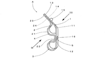
- FIG. 1 is a view showing a state before use of an example of a clamp according to the present invention
- FIG. 2 is a view showing a use state of the clamp shown in FIG. 1
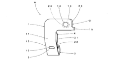
- FIG. 3 is a view from the III side of the clamp shown in FIG.
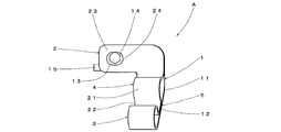
- FIG. 4 is a view as seen from the IV side of the clamp shown in FIG. 2 to 4 are diagrams of the clamp in a state where the long member is held (illustration of the long member is omitted).
- the clamp A connects two long members so as to hold the relative positions of the two long members, and is formed by bending a metal plate.
- the clamp A includes a first plate portion 1, a second plate portion 2, a first long member insertion portion 3, a second long member insertion portion 4, and an intermediate portion.
- the first plate portion 1 includes an upper holding portion 11 and an upper intermediate portion 12
- the second plate portion 2 includes a lower holding portion 21 and a lower intermediate portion 22.
- the clamp A has a configuration in which the first plate portion 1 and the second plate portion 2 are continuous.
- the first plate portion 1 and the second plate portion 2 are arranged so as to face each other, and in the vicinity of the portion where the first plate portion 1 and the second plate portion 2 are continuous, the first plate portion 1 and the second plate portion 2 are arranged.
- the two plate portions 2 form a first long member insertion portion 3 having a substantially circular shape and an inner diameter that is substantially the same as the outer diameter of the long member.
- the second plate portion 2 includes a lower holding portion 21 having a shape that forms a part of the second long member insertion portion 4 in the same manner as the first long member insertion portion 3.
- a lower intermediate portion 22 is provided between the lower holding portion 21 and the first elongate member insertion portion 3.
- the opposite side of the lower intermediate portion 22 in the lower holding portion 21 is bent in a direction away from the first plate portion 1, and a fixing portion 23 protruding in an L shape is provided.
- the fixing portion 23 is formed with a through hole 24 through which a fixing tool such as a screw passes.
- the through hole 24 is a long hole.
- the first plate portion 1 includes an upper intermediate portion 12 connected to the first elongated member insertion portion 3 and an upper holding portion 11 connected to the upper intermediate portion 12. . That is, the upper intermediate part 12 is formed between the upper holding part 11 and the first elongate member insertion part 3.
- the clamp A is bent in the direction away from the second plate portion 2 at the upper intermediate portion 12 at the tip side from the upper intermediate portion 12 in the first plate portion 1 before performing the press working. Furthermore, it is bent in the reverse direction (direction approaching the second plate part 2) in the middle of the upper holding part 11.
- the clamp A is a second long shape in which a long member can be held by the upper holding portion 11 and the lower holding portion 21 by bending the first plate portion 1 around the upper intermediate portion 12 by pressing.
- a member insertion portion 4 is formed (see FIGS. 2 to 4).
- the shape capable of holding the long member refers to a shape in which the long member cannot move when the long member is disposed inside the second long member insertion portion. 2
- the inner diameter of the long member insertion portion is substantially the same as the outer diameter of the long member.
- the front end side of the first plate part 1 approaches the second plate part 2 by pressing.
- tip part of the 2nd board part 2 contact.
- An L-shaped fixing portion 13 protruding in the same direction as the fixing portion 23 of the second plate portion 2 is formed at the tip portion of the first plate portion 1.
- the fixing portion 13 is formed with a through hole 14 through which a fixing tool such as a screw passes.
- a positioning portion 15 bent in a hook shape is formed at the tip of the fixed portion 13.
- the positioning portion 15 is used for positioning when the clamp A is fixed to a support member such as a bracket.
- a support member such as a bracket.
- the positioning member 15 is engaged with the support member to receive the weight or force. And fixing with a fixing tool can be performed quickly.
- an easy-to-curve portion 16 is formed in the upper intermediate portion 12 of the first plate portion 1.
- the bendable portion 16 has a through-hole formed in the center portion, and the cross-sectional area in the direction perpendicular to the bending direction of the first plate portion 1 by pressing the bendable portion 16 is different from that in the first plate portion 1.
- the cross-sectional area of the portion is smaller. Since the force acting on the first plate portion 1 during the pressing process is concentrated on the bendable portion 16, the energy required for bending the first plate portion 1 can be reduced. That is, the first plate portion 1 can be brought close to the second plate portion 2 with a small pressing force. From this, it is possible to reduce the size of the equipment used for the press working.
- the easy-to-bend portion 16 only needs to be configured to bend more easily than other portions.
- the through-hole is formed in the intermediate portion of the first plate portion 1, but is not limited thereto. Instead of this, a notch that intersects with the bending direction of the first plate portion 1 may be formed.
- the cross section is a structure that is biased to the center or one side in the width direction of the first plate portion 1.
- the first plate portion 1 When an in-plane shearing force is applied to the first plate portion 1 during the press working, the first plate portion 1 may be bent in the width direction by the bendable portion 16, and the first plate portion 1 and the second plate portion 2 As a result, the through holes 14 of the first plate portion 1 and the through holes 24 of the second plate portion 2 do not overlap. Therefore, it is preferable that the bendable portion 16 has a configuration in which at least the vicinity of both end portions in the width direction of the first plate portion 1 is connected.
- the bendable part 16 may be formed in the lower intermediate part 22, or may be formed in both the upper intermediate part 12 and the lower intermediate part 22.
- the first plate portion 1 or the second plate portion 2 is bent in the width direction at the bendable portion 16 during press working. It can reduce that the position where the 1 board part 1 and the 2nd board part 2 adjoin shifts.
- FIG. 5 is a diagram of the clamp in a state in which a long member is attached to the first long member insertion portion
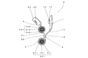
- FIG. 8 is a view showing an example of a use state of the clamp shown in FIG.
- a long member which is a control cable for operating a manual transmission of an automobile
- an operation member (not shown) provided inside the vehicle interior and a transmission (not shown) provided outside the vehicle interior are connected via two elongated members Ca1 and Ca2.
- the transmission can be controlled by operating the operation member.
- the long members Ca1 and Ca2 include an inner cable Iw1, an outer casing Oc1 in which the inner cable Iw1 is slidably housed, a casing cap Kc1 fixed to both ends of the outer casing Oc1, and an outer portion of the outer casing Oc1. And a sleeve Th1 that acts as a buffer member between the clamp A and the outer casing Oc1.
- the long member Ca2 includes an inner cable Iw2, an outer casing Oc2, and a sleeve Th2.
- the sleeves Th1 and Th2 are made of an elastic material such as rubber and are fixed to the surface of the outer casings Oc1 and Oc2, and the first long member insertion portion 3 or the second long member insertion portion 4 of the clamp A. Both end portions are formed in a flange shape so that the clamp A does not shift in the axial direction when inserted through.
- the sleeves Th1 and Th2 do not have to be provided. However, if the sleeves Th1 and Th2 are provided, vibration may cause noise due to the contact between the clamp A and the long members Ca1 and Ca2, or the long members Ca1 and Ca2 may be damaged. Can be further prevented.
- the clamp A is fixed to the supporting member provided in the side surface of the transmission mission case. Thereby, even if the vibration of the automobile is transmitted to the long members Ca1 and Ca2, the positions of the long members Ca1 and Ca2 do not change and can maintain a constant distance from each other and contact other members. Can also be prevented.
- the sleeve Th ⁇ b> 1 is inserted into the first long member insertion portion 3, and the flanges at both ends are protruded from the first long member insertion portion 3. .
- the outer casing Oc1 with the casing cap Kc1 fixed at one end is inserted into the sleeve Th1, and the outer casing Oc1 and the sleeve Th1 are fixed with an adhesive or the like.
- the casing cap Kc1 is fixed to the other end of the outer casing Oc1, and the inner cable Iw1 is inserted into the outer casing Oc1.
- the sleeve Th1 includes the flange-shaped portion as described above, the long member insertion Ca1 is difficult to be displaced from the first long member insertion portion 3 or to come off.
- the 1st elongate member insertion part 3 is a substantially circular shape determined beforehand as mentioned above, the internal diameter of the 1st elongate member insertion part 3 is set with the outer diameter of the elongate member to penetrate. By making it substantially the same, there is no possibility that the long member Ca1 is pressed from the first long member insertion portion 3 to be damaged or abnormal noise due to contact is generated.
- the long member Ca2 is disposed on the lower holding portion 21 so that the sleeve Th2 engages with the lower holding portion 21 from between the fixing portion 23 (see FIG. 6).
- the intermediate portion 5 including the upper intermediate portion 12 and the lower intermediate portion 22 is pressed, whereby the first plate portion 1 is changed to the second plate portion 2. Bend to the side. At this time, since the bendable portion 16 is formed in the upper intermediate portion 12 of the first plate portion 1, the stress due to press working concentrates on the bendable portion 16. The first plate portion 1 is bent from the upper intermediate portion 12 to the second plate portion 2 with the upper intermediate portion 12 as the center, the upper holding portion 11 approaches the lower holding portion 21, and the long member Ca2 is suppress. Thereby, the 2nd elongate member penetration part 4 comprised by the upper side holding
- the force at the time of pressing is concentrated on the easily-curved portion 16, it prevents the inner diameter of the first long member insertion portion 3 from being deformed into a shape different from the outer diameter of the long member Ca1 by the force at the time of pressing. It is possible to prevent local stress from acting on the long member Ca1 and the durability of the long member Ca1 to decrease. Moreover, generation
- the clamp A is configured such that the upper holding portion 11 is close to the lower holding portion 21 with the upper intermediate portion 12 as the center, and the fixing portion 13 of the first plate portion 1 and the fixing portion 23 of the second plate portion 2 are in contact with each other. Therefore, it can prevent that the 2nd elongate member insertion part 4 comprised by the upper side holding
- the two long members Ca ⁇ b> 1 and Ca ⁇ b> 2 can be connected to each other so that the first long member insertion portion 3 and the second long member insertion portion 4 hold the relative positions.
- the clamp A since the intermediate portion 5 is formed between the first long member insertion portion 3 and the second long member insertion portion 4, the long members Ca1 and Ca2 are separated by a predetermined distance ( The length of the intermediate portion 5) can be separated and fixed.
- the clamp A penetrates a fixing tool such as a screw through the through hole 14 formed in the fixing portion 13 of the first plate portion 1 and the through hole 24 formed in the fixing portion 23 of the second plate portion 2.
- FIG. 9 is a view showing another example of the clamp according to the present invention.
- FIG. 9 is a view of the clamp B before attaching the long member, and the same reference numerals are given to substantially the same parts as the clamp A shown in FIG.
- the first plate portion 1 ⁇ / b> B is formed in a flat plate shape from the first long member insertion portion 3 to the upper holding portion 11.
- the tip side of the lower intermediate portion 22 in the second plate portion 2B is bent in a direction away from the first plate portion 1B.
- An easy-to-curve portion 25 is formed in the lower intermediate portion 22.
- the shape of the easy music part 25 is the same shape as the easy music part 16.
- the procedure for connecting the long member with the clamp B is as follows. First, the long member Ca1 is attached to the first long member insertion portion 3 (corresponding to FIG. 5 in the clamp A), and the long member Ca2 is arranged in the lower holding portion 21 (corresponding to FIG. 6 in the clamp A). ). In this state, the intermediate part 5 is pressed and the second plate part 2B is deformed so that the lower holding part 21 approaches the upper holding part 11. At this time, since the bendable portion 25 is formed in the lower intermediate portion 22, the force acting on the second plate portion 2 during press working is concentrated on the bendable portion 25.
- the force during pressing prevents the inner diameter of the first elongate member insertion portion 3 from changing to a shape different from the outer diameter of the elongate member, local stress acts on the elongate member, Durability can be reduced, or abnormal noise generated by backlash between the first long member insertion portion 3 and the long member can be prevented.
- the clamp B is configured such that the lower holding portion 21 is close to the upper holding portion 11 with the lower intermediate portion 22 as the center, and the fixing portion 13 and the fixing portion 23 are in contact with each other. Therefore, the upper holding portion 11 and the lower holding portion are arranged. It can suppress that the 2nd elongate member penetration part 4 comprised by 21 presses a elongate member more than necessary. Thereby, it is possible to prevent local stress from acting on the long member and lowering the durability, or generating abnormal noise due to backlash between the second long member insertion portion 4 and the long member. .
- the bendable portion 25 is formed in the lower holding portion 21 and the second plate portion 2 is bent.
- the bendable portion 16 similar to the clamp A is also provided in the clamp B.
- a configuration may be adopted in which the first plate portion 1 is bent so as to be formed on the first plate portion 1B and to bring the upper holding portion 11 closer to the lower holding portion 21 around the upper intermediate portion 12.
- the shape of the clamp B can be bent at the intermediate portion 5, and the shape of the clamp B can be matched to the shape of the portion to which the clamp B can be attached (in the above example, the transmission case bracket). it can.
- FIGS. 10 to 12 are views showing a procedure for attaching the long member to the clamp according to the present invention.
- 10 is a view showing a state in which one long member is attached to another example of the clamp according to the present invention
- FIG. 11 is a view showing a state in which two long members are attached to the clamp shown in FIG.
- FIG. 12 is a diagram showing a state in which three long members are attached by the clamp shown in FIG. 11.
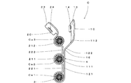
- the clamp C shown in FIGS. 10 to 12 holds three long members Ca1, Ca2, and Ca3 as long members. Note that, in each part of the clamp C, the same reference numerals are given to substantially the same parts as the clamp A.
- the clamp C has a configuration in which the first plate portion 1C and the second plate portion 2C are continuous.
- the first plate portion 1C and the second plate portion 2C are disposed so as to face each other, and in the vicinity of the portion where the first plate portion 1C and the second plate portion 2C are continuous, the first plate portion 1C and the second plate portion 2C are arranged.
- the two plate portions 2C form a first long member insertion portion 3 having a substantially circular shape and an inner diameter that is substantially the same as the outer diameter of the long member.
- the second plate portion 2 ⁇ / b> C includes a first lower holding portion 211 and a second lower holding portion 212 having a shape that forms a part of the second long member insertion portion 4 in the same manner as the first long member insertion portion 3. ing.
- the first lower holding portion 211 is formed next to the first long member insertion portion 3, and the second lower holding portion 212 is opposite to the first long member insertion portion 3 of the first lower holding portion 211.
- the first lower intermediate portion 221 is interposed between the first lower holding portion 211 and the first elongate member insertion portion 3, and the first lower holding portion 211 and the second lower holding portion 212 are 2 Lower intermediate part 222 is formed.
- a fixing portion 23 that protrudes in an L shape is provided on the distal end side of the second lower holding portion 212.
- the fixing portion 23 is formed with a through hole 24 through which a fixing tool such as a screw passes.
- the through hole 24 is a long hole.
- the first plate portion 1C includes a first upper intermediate portion 121 connected to the first elongated member insertion portion 3, a first upper holding portion 111 connected to the first upper intermediate portion 121, and a first upper portion.
- a second upper intermediate portion 122 connected to the holding portion 111 and a second upper holding portion 112 connected to the second upper intermediate portion 122 are provided. That is, the first upper intermediate part 121 is formed between the first upper holding part 111 and the first elongate member insertion part 3, and the second upper intermediate part 122 is the second upper holding part 112 and the first upper holding part. 111. As shown in FIG.
- the clamp C is separated from the second plate portion 2C at the first upper intermediate portion 121 at the tip side from the first upper intermediate portion 121 in the first plate portion 1C before the lapping process is performed. It is bent in the direction. Furthermore, the front end side of the first plate portion 1C relative to the second upper intermediate portion 122 is bent at the second upper intermediate portion 122 in a direction away from the second plate portion 2C.
- the second upper holding part 112 is bent in the reverse direction (direction approaching the second plate part 2C).
- the bendable part 16 is formed in both the first upper intermediate part 121 and the second upper intermediate part 122.
- the long member Ca1 is attached to the first long member insertion portion 3, and the long member Ca2 is disposed in the first lower holding portion 211 (see FIG. 10).
- press working is performed to bring the first upper holding portion 111 closer to the first lower holding portion 211.
- the first plate portion 1 ⁇ / b> C is bent around the first upper intermediate portion 121.
- the force concentrates on the bendable portion 16 of the first upper intermediate portion 121, so that the first upper holding portion 111, the first lower holding portion 211, and the first long member insertion portion 3 are pressed.
- the 1st upper side support part 111 presses elongate member Ca2 (refer FIG. 11).
- the long member Ca ⁇ b> 2 is attached to the second long member insertion portion 4 including the first upper support portion 111 and the first lower support portion 211.
- the second upper intermediate portion 122 is formed so as to come into contact with the second lower intermediate portion 222. Thereby, it can suppress that the 1st upper side support part 111 presses down elongate member Ca2 strongly. Note that the press work for causing the first upper holding portion 111 to approach the first lower holding portion 211 is performed so that no force acts on the second upper holding portion 112.
- the long member Ca3 is disposed on the second lower holding portion 212 (see FIG. 11).
- press working is performed so that the second upper holding portion 112 approaches the second lower holding portion 212.
- the force by the press work is concentrated on the easy-to-curve portion 16 formed in the second upper intermediate portion 122.
- the first plate portion 1C is bent so that the second upper holding portion 112 approaches the second lower intermediate portion 222 around the second upper intermediate portion 122, and the second upper holding portion 112 is a long member.
- Press Ca3 (see FIG. 12).
- the long member Ca ⁇ b> 3 is attached to the third long member insertion portion 6 including the second upper support portion 112 and the second lower support portion 212.
- the fixing portion 13 When the first plate portion 1C is deformed by press working, the fixing portion 13 is configured to come into contact with the fixing portion 23 of the second plate portion 1C, and thus includes the second upper holding portion 112 and the second lower holding portion 212. It is possible to prevent the third long member insertion portion 6 from pressing the long member Ca3 more than necessary. Thereby, it can prevent that local stress acts on elongate member Ca3, and durability of elongate member Ca2 falls. Generation of play between the third long member insertion portion 6 and the long member Ca3 can be prevented, and abnormal noise due to contact between the second long member insertion portion 4 and the long member Ca2 can be prevented.
- the long members Ca1, Ca2, and Ca3, which are three long members are respectively the first long member insertion portion 3, the second long member insertion portion 4, and the third long member insertion portion. 6 can be connected to maintain the relative position.
- the long members Ca1, Ca2, and Ca3, which are long members can be connected at a predetermined distance.
- the clamp C passes through a fixing tool such as a screw through the through hole 14 formed in the fixing portion 13 of the first plate portion 1C and the through hole 24 formed in the fixing portion 23 of the second plate portion 2C.
- the three long members are connected to each other while maintaining a predetermined interval.
- a larger number of long members can be connected by bending the distal end side of the first plate portion at a plurality of locations. It is also possible to adopt a configuration.
- the present invention can be used as a clamp that holds long members such as a plurality of control cables and pipes together.
Landscapes
- Engineering & Computer Science (AREA)
- General Engineering & Computer Science (AREA)
- Mechanical Engineering (AREA)
- Architecture (AREA)
- Civil Engineering (AREA)
- Structural Engineering (AREA)
- Clamps And Clips (AREA)
- Supports For Pipes And Cables (AREA)
- Mutual Connection Of Rods And Tubes (AREA)
- Installation Of Indoor Wiring (AREA)
Abstract
金属板を折り曲げて形成され、2つの長尺部材の相対位置を保持するように、2つの長尺部材を連結するクランプにおいて、クランプは、第1板部と、第1板部と連続している第2板部と、第1板部と第2板部とにより形成され、形状がほぼ円形であり、その内径が長尺部材の外径とほぼ同一である第1長尺部材挿通部と、第1板部に形成された上側保持部と、第2板部に形成された下側保持部とから構成される第2長尺部材挿通部と、第1長尺部材挿通部と上側保持部との間に設けられた上側中間部と、第1長尺部材挿通部と下側保持部との間に設けられた下側中間部とを有し、上側中間部と下側中間部とを含む中間部をプレス加工することにより、第2長尺部材挿通部が長尺部材を保持可能な形状となる。
Description
本発明は、複数の長尺部材の相対位置を保持するように連結するクランプに関するものである。
従来、相対位置を保持するように、複数の長尺部材を連結するクランプが提案されている。例えば特許文献1には、対をなす湾曲部で保持部を構成し、その保持部に塑性変形しやすくした変形部が設けられたクリップが記載されている。また、特許文献2には、加締めることで肉薄の部分を縮径方向へ塑性変形させて配管に取り付けた配管固定用ブラケットが記載されている。
上述のようなクランプは、予め開いた状態の部材に長尺部材を挿通したのち、プレス加工によってクランプを閉じることで長尺部材を保持する構成となっている。前記クランプにおいて、プレス加工をし易くするために、プレス加工時の折り曲げの起点となる部分に易曲部を設けている。
しかしながら、特許文献1のクリップや特許文献2のブラケットでは、長尺部材を挿通する部分に前記易曲部が設けられている。そのため、プレス加工時に長尺部材挿通部分が長尺部材の外径形状と異なる形状に変形し、長尺部材に局所的な応力が加わって長尺部材の耐久性が低下したり、長尺部材とのガタが大きくなって異音が発生したりするおそれがある。
そこで本発明は、複数の長尺部材を安定して保持でき、長尺部材の耐久性が低下したり、長尺部材との間で異音が発生したりするおそれのないクランプを提供することを目的とする。
上記目的を達成するために本発明は、金属板を折り曲げて形成され、2つの長尺部材の相対位置を保持するように、2つの長尺部材を連結するクランプにおいて、前記クランプは、第1板部と、前記第1板部と連続している第2板部と、前記第1板部と前記第2板部とにより形成され、形状がほぼ円形であり、その内径が前記長尺部材の外径とほぼ同一である第1長尺部材挿通部と、前記第1板部に形成された上側保持部と、前記第2板部に形成された下側保持部とから構成される第2長尺部材挿通部と、前記第1長尺部材挿通部と前記上側保持部との間に設けられた上側中間部と、前記第1長尺部材挿通部と前記下側保持部との間に設けられた下側中間部とを有し、前記上側中間部と前記下側中間部とを含む中間部をプレス加工することにより、前記第2長尺部材挿通部が長尺部材を保持可能な形状となることを特徴とする。
(1)本発明によると、第1長尺部材挿通部と、第2長尺部材挿通部との間に設けられた中間部をプレス加工するので、プレス加工の力が第2長尺部材挿通部に加わらず、第2長尺部材挿通部が長尺部材を保持可能な形状になる。これにより、長尺部材を安定して保持でき、耐久性が低下したり、異音が発生したりするおそれがない。
(2)本発明のクランプを、前記中間部が、易曲部を有する構成とすることで、プレス加工の力が易曲部に加わるので、プレス加工が確実となる。また、プレス加工するときの力を小さくできるので、プレスの設備を小型化でき、製造が容易となる。
(3)本発明のクランプを、前記易曲部が、前記上側中間部または前記下側中間部のどちらか一方に設けられている構成とすることで、第1板部または第2板部のどちらか一方だけをプレス加工するので、プレス加工が容易である。また、プレス加工後の第1板部と第2板部との位置ずれが生じ難い。
(4)本発明のクランプを、前記易曲部が、穴を含むように構成されることで、プレス加工時に中間部の曲がる方向が安定するので、プレス加工後の第1板部と第2板部との位置ずれが一層生じ難い。
(5)本発明によると、一の長尺部材挿通部と、一の長尺部材挿通部に隣接する他の長尺部材挿通部との間にある中間部をプレス加工するので、プレス加工の力が他の長尺部材挿通部に加わらず、他の長尺部材挿通部が長尺部材を保持可能な形状になる。これにより、長尺部材を安定して保持でき、耐久性が低下したり、異音が発生したりするおそれがない。
以下に本発明の実施形態を図面を参照して説明する。
(第1の実施形態)
図1は本発明にかかるクランプの一例の使用前の状態を示す図であり、図2は図1に示すクランプの使用状態を示す図であり、図3は図2に示すクランプのIII側から見た図であり、図4は図2に示すクランプのIV側から見た図である。なお、図2~図4は長尺部材を保持した状態(長尺部材の図示は省略している)のクランプの図である。
図1は本発明にかかるクランプの一例の使用前の状態を示す図であり、図2は図1に示すクランプの使用状態を示す図であり、図3は図2に示すクランプのIII側から見た図であり、図4は図2に示すクランプのIV側から見た図である。なお、図2~図4は長尺部材を保持した状態(長尺部材の図示は省略している)のクランプの図である。
本発明にかかるクランプAは、2つの長尺部材の相対位置を保持するように、2つの長尺部材を連結するものであり、金属板を折り曲げて形成されている。図1~図4に示すように、クランプAは、第1板部1と、第2板部2と、第1長尺部材挿通部3と、第2長尺部材挿通部4と、中間部5とを備えている。第1板部1は、上側保持部11と、上側中間部12とを備え、第2板部2は、下側保持部21と、下側中間部22とを有している。
そして、上側中間部12と下側中間部22とを含む中間部5をプレス加工することにより、上側保持部11を下側保持部21に近接させ、第2長尺部材挿通部4が長尺部材を保持可能な形状となる(図2~図4参照)。以下に、各部の詳細について、それぞれ、対応する図面を参照しつつ説明する。また、上側中間部12には、易曲部16が形成されている。
図1~図4に示すように、クランプAは、第1板部1と第2板部2とが連続した構成となっている。第1板部1と第2板部2とは対向するように配置されており、第1板部1と第2板部2とが連続する部分の近傍には、第1板部1と第2板部2とによって、形状がほぼ円形で、その内径が長尺部材の外径とほぼ同一の第1長尺部材挿通部3が形成されている。
図1に示すように、第2板部2は、第1長尺部材挿通部3と同様に第2長尺部材挿通部4の一部をなす形状の下側保持部21を備えており、下側保持部21と第1長尺部材挿通部3との間に下側中間部22が備えられている。下側保持部21における下側中間部22の反対側は第1板部1と離反する方向に屈曲しており、L字状に突出した固定部23が備えられている。固定部23には、ねじ等の固定具が貫通する貫通孔24が形成されている。なお、貫通孔24は長孔である。
図1に示すように第1板部1は、第1長尺部材挿通部3と連設された上側中間部12と、上側中間部12に連設された上側保持部11とを備えている。すなわち、上側中間部12は上側保持部11と第1長尺部材挿通部3との間に形成されている。図1に示すように、クランプAは、プレス加工を行う前、第1板部1における上側中間部12よりも先端側は、上側中間部12で第2板部2から離れる方向に折り曲げられており、さらに上側保持部11の途中で逆向き(第2板部2に接近する向き)に折り曲げられている。クランプAは、プレス加工で上側中間部12を中心に第1板部1を折り曲げることで、上側保持部11と下側保持部21とで長尺部材を保持可能な形状である第2長尺部材挿通部4が形成される(図2~図4参照)。ここで、長尺部材を保持可能な形状とは、第2長尺部材挿通部の内部に長尺部材が配置されたときに、長尺部材が移動できないような形状のことを指し、例えば第2長尺部材挿通部の内径が長尺部材の外径とほぼ同一な形状などである。
第1板部1における上側保持部11の途中で第2板部2に接近するように折り曲げられていることで、プレス加工によって、第1板部1の先端側を第2板部2に接近させたとき、第1板部1の先端部分と第2板部2の先端部分とは接触する。第1板部1の先端部分には、第2板部2の固定部23と同じ方向に突出したL字状の固定部13が形成されている。固定部13には、ねじ等の固定具が貫通する貫通孔14が形成されている。固定部13の先端には、鉤状に屈曲した位置決め部15が形成されている。
位置決め部15は、クランプAをブラケットなどの支持部材に固定するときの位置決めに用いるものである。長尺部材が重量物であったり、長尺部材の弾性力でクランプAに大きな力が作用したりする場合において、位置決め部15を支持部材に係合させることで、重量或いは力を受けることができ、固定具による固定を迅速に行うことができる。
図2等に示すように、第1板部1における上側中間部12には易曲部16が形成されている。易曲部16には、中央部分に貫通孔が形成されており、易曲部16のプレス加工による第1板部1の折り曲げ方向と直交する方向の断面積は、第1板部1における他の部分の断面積よりも小さくなっている。プレス加工時に第1板部1に作用する力が易曲部16に集中するので、第1板部1の折り曲げに要するエネルギを小さくすることができる。すなわち、小さなプレス力で第1板部1を第2板部2に近接させることができる。このことから、プレス加工に用いられる設備を小型化することが可能である。
なお、易曲部16は他の部分よりも曲がり易いように構成してあればよく、本実施形態では第1板部1の中間部分に貫通孔を形成する構成としているが、これに限定されるものではなく、第1板部1の折り曲げ方向と交差する切り欠きを形成するものであってもよい。しかしながら、切り欠きを形成する構造の場合、断面が第1板部1の幅方向の中央或いは片方に偏った構造となる。プレス加工時に第1板部1に面内せん断力が作用すると、第1板部1が易曲部16で幅方向に曲がってしまうことがあり、第1板部1と第2板部2との近接する位置がずれて第1板部1の貫通孔14と第2板部2の貫通孔24とが重ならなくなってしまう。そのため、易曲部16は少なくとも、第1板部1の幅方向の両端部近傍が連結している構成であることが好ましい。易曲部16は下側中間部22に形成してもよく、上側中間部12と下側中間部22の両方に形成してもよい。上側中間部12または下側中間部22のどちらか一方に形成することで、プレス加工時に第1板部1または第2板部2が易曲部16で幅方向に曲がってしまうことによる、第1板部1と第2板部2との近接する位置がずれることを低減できる。
次に、クランプAに長尺部材を取り付ける手順について図面を参照して説明する。図5は第1長尺部材挿通部に長尺部材を取り付けた状態のクランプの図であり、図6は図5に示すクランプの下側保持部に長尺部材を配置した状態の図であり、図7は第2長尺部材挿通部で長尺部材を取り付けた状態の図であり、図8は図1に示すクランプの使用状態の一例を示す図である。
以下の説明では、図8に示すように、本発明にかかるクランプAに、自動車のマニュアルトランスミッションを操作するためのコントロールケーブルである長尺部材を取り付けるものを例に説明する。自動車のトランスミッションでは、車室内部に備えられた操作部材(不図示)と車室外部に備えられたトランスミッション(不図示)とが2本の長尺部材Ca1、Ca2を介して、接続されており、操作部材を操作することでトランスミッションの制御を行うことができる。
長尺部材Ca1、Ca2は、インナーケーブルIw1と、内部にインナーケーブルIw1が摺動可能に収納されるアウターケーシングOc1と、アウターケーシングOc1の両端に固定されるケーシングキャップKc1と、アウターケーシングOc1の外部に取り付けられクランプAと、アウターケーシングOc1との緩衝部材として作用するスリーブTh1とを備えている。長尺部材Ca2も同様に、インナーケーブルIw2、アウターケーシングOc2及びスリーブTh2を備えている。スリーブTh1、Th2は、ゴム等の弾性を有する材料で形成されてアウターケーシングOc1、Oc2の表面に固定されており、クランプAの第1長尺部材挿通部3又は第2長尺部材挿通部4に挿通したとき、クランプAが軸方向にずれないように両端部分がフランジ状に構成されている。
前記スリーブTh1、Th2は備えなくてもよいが、備えることによって、振動でクランプAと長尺部材Ca1、Ca2の接触によって異音の原因になったり、長尺部材Ca1、Ca2をいためてしまったりするのを一層防ぐことができる。なお、図示は省略しているが、クランプAはトランスミッションのミッションケースの側面に設けられた支持部材へ固定されるものである。これにより、自動車の振動が長尺部材Ca1、Ca2に伝達されても、長尺部材Ca1、Ca2の位置が変わらず、互いに一定の間隔を維持し続けることができるとともに、他の部材に接触するのも防ぐことが可能である。
以下にクランプAで2本の長尺部材Ca1、Ca2を連結する手順について説明する。まず、図1に示しているように、本発明にかかるクランプAにおいて、第1長尺部材挿通部3へスリーブTh1を挿入して、両端のフランジを第1長尺部材挿通部3から突出させる。次に一端にケーシングキャップKc1が固定されたアウターケーシングOc1をスリーブTh1へ挿通して、アウターケーシングOc1とスリーブTh1とを接着剤等で固定する。続いてアウターケーシングOc1の他端にケーシングキャップKc1を固定し、インナーケーブルIw1をアウターケーシングOc1へ挿通する。なお、スリーブTh1は上述のようにフランジ状の部分を備えているので、長尺部材挿通Ca1は、第1長尺部材挿通部3からずれたり、抜けたりしにくい。
また、上述のように、第1長尺部材挿通部3は予め決められたほぼ円形の形状であることから、第1長尺部材挿通部3の内径を、挿通する長尺部材の外径とほぼ同一とすることで、長尺部材Ca1が第1長尺部材挿通部3から押えられて、損傷したり、接触による異音が発生したりするおそれがない。
第1長尺部材挿通部3に長尺部材Ca1を挿通した後、第1板部1と第2板部2の間から、つまり、第1板部1の固定部13と第2板部2の固定部23との間から、スリーブTh2が下側保持部21に係合するように、長尺部材Ca2を下側保持部21に配置する(図6参照)。
長尺部材Ca2を下側保持部21に配置した状態で、上側中間部12と下側中間部22とを含む中間部5をプレス加工することにより、第1板部1を第2板部2側に折り曲げる。このとき、第1板部1の上側中間部12には、易曲部16が形成されているので、プレス加工による応力が易曲部16に集中する。第1板部1は上側中間部12より先端側が、上側中間部12を中心に第2板部2側に折り曲げられ、上側保持部11は下側保持部21に接近し、長尺部材Ca2を押える。これにより、上側保持部11及び下側保持部21で構成される第2長尺部材挿通部4が長尺部材Ca2を保持する(図7参照)。
プレス加工時の力は易曲部16に集中することから、プレス加工時の力によって、第1長尺部材挿通部3の内径が長尺部材Ca1の外径と異なる形状に変形するのを防ぎ、長尺部材Ca1に局所的な応力が作用し、長尺部材Ca1の耐久性が低下したりするのを防ぐことができる。また、第1長尺部材挿通部3と長尺部材Ca1とのガタの発生を防ぎ、第1長尺部材挿通部3と長尺部材Ca1との接触による異音を防ぐことができる。
クランプAが、上側中間部12を中心に上側保持部11が下側保持部21に近接し、第1板部1の固定部13と第2板部2の固定部23が接触する構成であるので、上側保持部11と下側保持部21で構成される第2長尺部材挿通部4が、長尺部材Ca2を必要以上に押さえつけるのを防ぐことができる。これにより、長尺部材Ca2に局所的な応力が作用し、長尺部材Ca2の耐久性が低下したりするのを防ぐことができる。第2長尺部材挿通部4と長尺部材Ca2とのガタの発生を抑制し、第2長尺部材挿通部4と長尺部材Ca2との接触による異音を防ぐことができる。
以上のようにして、2本の長尺部材Ca1、Ca2をそれぞれ、第1長尺部材挿通部3及び第2長尺部材挿通部4で相対位置を保持するように連結することができる。クランプAにおいて、第1長尺部材挿通部3と第2長尺部材挿通部4との間には中間部5が形成されているので、クランプAで長尺部材Ca1、Ca2を所定の距離(中間部5の長さ)を離して固定することができる。また、クランプAは、第1板部1の固定部13に形成された貫通孔14と、第2板部2の固定部23に形成された貫通孔24とにねじ等の固定具を貫通し、そのねじをトランスミッションのミッションケースのブラケット(不図示)等に螺合するので、振動や長尺部材Ca2に作用する力によって、下側保持部21と上側保持部11とが開くのを防ぐことができる。これにより、長尺部材Ca1、Ca2を確実に保持することができる。
(第2の実施形態)
本発明にかかるクランプの他の例について図面を参照して説明する。図9は本発明にかかるクランプの他の例を示す図である。図9は長尺部材を取り付ける前のクランプBの図であり、図1に示すクランプAと実質上同じ部分には、同じ符号が付してある。
本発明にかかるクランプの他の例について図面を参照して説明する。図9は本発明にかかるクランプの他の例を示す図である。図9は長尺部材を取り付ける前のクランプBの図であり、図1に示すクランプAと実質上同じ部分には、同じ符号が付してある。
図9に示すように、クランプBは、第1板部1Bが第1長尺部材挿通部3から上側保持部11まで平板状に形成されている。第2板部2Bにおける下側中間部22より先端側が、第1板部1Bから離れる方向に屈曲している。下側中間部22には易曲部25が形成されている。なお、易曲部25の形状は易曲部16と同じ形状である。
クランプBで長尺部材を連結する手順は次のとおりである。まず、第1長尺部材挿通部3に長尺部材Ca1を取り付け(クランプAにおいて、図5に相当)、下側保持部21に長尺部材Ca2を配置する(クランプAにおいて、図6に相当)。この状態で、中間部5にプレス加工を施し、下側保持部21を上側保持部11に接近するよう第2板部2Bを変形する。このとき、下側中間部22に易曲部25が形成されているので、プレス加工時に第2板部2に作用する力は易曲部25に集中する。
プレス加工時の力によって、第1長尺部材挿通部3の内径が長尺部材の外径と異なる形状に変形するのを防ぎ、長尺部材に局所的な応力が作用し、長尺部材の耐久性が低下したり、第1長尺部材挿通部3と長尺部材とのガタにより発生する異音を防ぐことができる。
クランプBは、下側中間部22を中心に下側保持部21が上側保持部11に近接し、固定部13と固定部23が接触する構成であるので、上側保持部11と下側保持部21で構成される第2長尺部材挿通部4が、長尺部材を必要以上に押さえつけるのを抑制することができる。これにより、長尺部材に局所的な応力が作用し耐久性が低下したり、第2長尺部材挿通部4と長尺部材とのガタによる異音が発生したりするのを防ぐことができる。
クランプBのように、下側保持部21が図9中上方へ大きく開放されるような形状のものを用いることで、長尺部材を下側保持部21へ配置し易くなり、長尺部材を下側保持部21に更に安定して配置することが可能である。
なお、本実施形態では、下側保持部21に易曲部25が形成され、第2板部2を曲げる構成となっているが、クランプBにおいても、クランプAと同様の易曲部16を第1板部1Bに形成しておき、上側中間部12を中心に上側保持部11を下側保持部21に近づけるように、第1板部1を折り曲げる構成であってもよい。この構成によると、クランプBの形状を中間部5で折れ曲がった形状とすることができ、クランプBの形状を取り付けられる部分(上述の例では、トランスミッションのミッションケースのブラケット)の形状に合わせることができる。
(第3の実施形態)
本発明にかかるクランプのさらに他の例について図面を参照して説明する。図10~図12は本発明にかかるクランプに長尺部材を取り付ける手順を示す図である。図10は、本発明にかかるクランプの他の例に1本の長尺部材取り付けた状態の図であり、図11は図10に示すクランプに2本の長尺部材を取り付けた状態の図であり、図12は、図11に示すクランプで3本の長尺部材を取り付けた状態の図である。図10~図12に示すクランプCは長尺部材として3本の長尺部材Ca1、Ca2、Ca3を保持するものである。なお、クランプCの各部において、クランプAと実質上同じ部分には、同じ符号が付してある。
本発明にかかるクランプのさらに他の例について図面を参照して説明する。図10~図12は本発明にかかるクランプに長尺部材を取り付ける手順を示す図である。図10は、本発明にかかるクランプの他の例に1本の長尺部材取り付けた状態の図であり、図11は図10に示すクランプに2本の長尺部材を取り付けた状態の図であり、図12は、図11に示すクランプで3本の長尺部材を取り付けた状態の図である。図10~図12に示すクランプCは長尺部材として3本の長尺部材Ca1、Ca2、Ca3を保持するものである。なお、クランプCの各部において、クランプAと実質上同じ部分には、同じ符号が付してある。
図10~図12に示すように、クランプCは、第1板部1Cと第2板部2Cとが連続した構成となっている。第1板部1Cと第2板部2Cとは対向するように配置されており、第1板部1Cと第2板部2Cとが連続する部分の近傍には、第1板部1Cと第2板部2Cとによって、形状がほぼ円形であり、内径が長尺部材の外径とほぼ同一の第1長尺部材挿通部3が形成されている。
第2板部2Cは、第1長尺部材挿通部3と同様に第2長尺部材挿通部4の一部をなす形状の第1下側保持部211及び第2下側保持部212を備えている。第1下側保持部211が第1長尺部材挿通部3の隣に形成されており、第2下側保持部212は第1下側保持部211の第1長尺部材挿通部3と反対側に形成されている。そして、第1下側保持部211と第1長尺部材挿通部3との間に第1下側中間部221が、第1下側保持部211と第2下側保持部212の間に第2下側中間部222が形成されている。第2下側保持部212の先端側は、L字状に突出した固定部23が備えられている。固定部23には、ねじ等の固定具が貫通する貫通孔24が形成されている。なお、貫通孔24は長孔である。
第1板部1Cは、第1長尺部材挿通部3と連設された第1上側中間部121と、第1上側中間部121に連設された第1上側保持部111と、第1上側保持部111と連設された第2上側中間部122と、第2上側中間部122と連設された第2上側保持部112とを備えている。すなわち、第1上側中間部121は第1上側保持部111と第1長尺部材挿通部3との間に形成され、第2上側中間部122は第2上側保持部112と第1上側保持部111との間に形成されている。図10等に示すように、クランプCは、レス加工を行う前、第1板部1Cにおける第1上側中間部121よりも先端側は、第1上側中間部121で第2板部2Cから離れる方向に折り曲げられている。さらに、第1板部1Cにおける第2上側中間部122よりも先端側は、第2上側中間部122で第2板部2Cから離れる方向に折り曲げられている。
そして、さらに第2上側保持部112の途中で逆向き(第2板部2Cに接近する向き)に折り曲げられている。第1上側中間部121及び第2上側中間部122の両方に易曲部16が形成されている。
クランプCによる長尺部材の連結の手順について説明する。まず、第1長尺部材挿通部3に長尺部材Ca1を取り付け、第1下側保持部211に長尺部材Ca2を配置する(図10参照)。長尺部材Ca2を第1下側保持部211に配置した状態で、プレス加工を施し、第1上側保持部111を第1下側保持部211に接近させる。このとき、第1上側中間部121を中心に、第1板部1Cが折れ曲がる。プレス加工を行うとき、第1上側中間部121の易曲部16に力が集中するので、第1上側保持部111、第1下側保持部211及び第1長尺部材挿通部3がプレス加工時の力で変形しにくい。これにより、第1上側支持部111が長尺部材Ca2を押える(図11参照)。以上のようにして、長尺部材Ca2は、第1上側支持部111と第1下側支持部211とで構成される第2長尺部材挿通部4に取り付けられる。
第1板部1Cはプレス加工によって変形すると、第2上側中間部122が第2下側中間部222と接触するように形成されている。これにより、第1上側支持部111が長尺部材Ca2を強く押えるのを抑制することができる。なお、第1上側保持部111を第1下側保持部211に接近させるためのプレス加工は、第2上側保持部112に力が作用しないように行われる。
長尺部材Ca1及びCa2が第1長尺部材挿通部3及び第2長尺部材挿通部4に取り付けられた状態で、第2下側保持部212に長尺部材Ca3を配置する(図11参照)。この状態で、第2上側保持部112が第2下側保持部212に接近するようにプレス加工を施す。このとき、プレス加工による力は、第2上側中間部122に形成されている易曲部16に集中する。これにより、第1板部1Cは、第2上側保持部112が第2上側中間部122を中心に第2下側中間部222に接近するように折れ曲がり、第2上側保持部112は長尺部材Ca3を押える(図12参照)。以上のようにして、長尺部材Ca3が第2上側支持部112と第2下側支持部212とで構成される第3長尺部材挿通部6に取り付けられる。
第1板部1Cはプレス加工によって変形すると、固定部13が第2板部1Cの固定部23と接触する構成であるので、第2上側保持部112と第2下側保持部212で構成される第3長尺部材挿通部6が、長尺部材Ca3を必要以上に押さえつけるのを防ぐことができる。これにより、長尺部材Ca3に局所的な応力が作用し、長尺部材Ca2の耐久性が低下したりするのを防ぐことができる。第3長尺部材挿通部6と長尺部材Ca3とのガタの発生を防ぎ、第2長尺部材挿通部4と長尺部材Ca2との接触による異音を防ぐことができる。
以上のようにして、3本の長尺部材である長尺部材Ca1、Ca2、Ca3をそれぞれ、第1長尺部材挿通部3、第2長尺部材挿通部4及び第3長尺部材挿通部6で相対位置を保持するように連結することができる。クランプCにおいて、長尺部材である長尺部材Ca1、Ca2、Ca3を所定の距離を離して連結することができる。クランプCは、第1板部1Cの固定部13に形成された貫通孔14と、第2板部2Cの固定部23に形成された貫通孔24とにねじ等の固定具を貫通し、該ねじをトランスミッションのミッションケースのブラケット(不図示)等に螺合するので、振動や長尺部材Ca2、Ca3に作用する力によって、第1板部1Cと第2板部2Cとが離れるのを抑制することができる。これにより、長尺部材Ca1、Ca2、Ca3を確実に保持することができる。
なお、本実施形態では3個の長尺部材を所定の間隔を保持して連結するものとしているが、第1板部の先端側を複数箇所で折り曲げることで、さらに多くの長尺部材を連結する構成とすることも可能である。
本発明は複数本のコントロールケーブルやパイプなどの長尺部材をまとめて保持するクランプとして利用することが可能である。
A~C クランプ
1 第1板部
11 上側保持部
12 上側中間部
13 固定部
14 貫通孔
15 位置決め部
16 易曲部
2 第2板部
21 下側保持部
22 下側中間部
23 固定部
24 貫通孔
3 第1長尺部材挿通部
4 第2長尺部材挿通部
5 中間部
1 第1板部
11 上側保持部
12 上側中間部
13 固定部
14 貫通孔
15 位置決め部
16 易曲部
2 第2板部
21 下側保持部
22 下側中間部
23 固定部
24 貫通孔
3 第1長尺部材挿通部
4 第2長尺部材挿通部
5 中間部
Claims (5)
- 金属板を折り曲げて形成され、2つの長尺部材の相対位置を保持するように、2つの長尺部材を連結するクランプにおいて、
前記クランプは、第1板部と、
前記第1板部と連続している第2板部と、
前記第1板部と前記第2板部とにより形成され、形状がほぼ円形であり、その内径が前記長尺部材の外径とほぼ同一である第1長尺部材挿通部と、
前記第1板部に形成された上側保持部と、
前記第2板部に形成された下側保持部とから構成される第2長尺部材挿通部と、
前記第1長尺部材挿通部と前記上側保持部との間に設けられた上側中間部と、
前記第1長尺部材挿通部と前記下側保持部との間に設けられた下側中間部とを有し、
前記上側中間部と前記下側中間部とを含む中間部をプレス加工することにより、前記第2長尺部材挿通部が長尺部材を保持可能な形状となることを特徴とするクランプ。 - 前記中間部は、易曲部を有することを特徴とする請求項1記載のクランプ。
- 前記易曲部は、前記上側中間部または前記下側中間部のどちらか一方に設けられていることを特徴とする請求項2記載のクランプ。
- 前記易曲部は、穴を含むように構成されることを特徴とする請求項3記載のクランプ。
- 金属板を折り曲げて形成され、複数の長尺部材の相対位置を保持するように、複数の長尺部材を連結するクランプにおいて、
前記クランプは、第1板部と、
前記第1板部と連続している第2板部と、
複数の長尺部材挿通部とを有し、
前記複数の長尺部材挿通部は、
前記第1板部と前記第2板部とにより形成され、形状がほぼ円形であり、その内径が前記長尺部材の外径とほぼ同一である一の長尺部材挿通部と、
前記一の長尺部材挿通部に隣接し、前記第1板部に形成された上側保持部と、前記第2板部に形成された下側保持部とから構成される他の長尺部材挿通部とを含み、
前記一の長尺部材挿通部と前記上側保持部との間には上側中間部が設けられ、
前記一の長尺部材挿通部と前記下側保持部との間には下側中間部が設けられており、
前記上側中間部と前記下側中間部とを含む中間部をプレス加工することにより、前記他の長尺部材挿通部が長尺部材を保持可能な形状となることを特徴とするクランプ。
Applications Claiming Priority (2)
| Application Number | Priority Date | Filing Date | Title |
|---|---|---|---|
| JP2011101161 | 2011-04-28 | ||
| JP2011-101161 | 2011-04-28 |
Publications (1)
| Publication Number | Publication Date |
|---|---|
| WO2012147796A1 true WO2012147796A1 (ja) | 2012-11-01 |
Family
ID=47072313
Family Applications (1)
| Application Number | Title | Priority Date | Filing Date |
|---|---|---|---|
| PCT/JP2012/061094 Ceased WO2012147796A1 (ja) | 2011-04-28 | 2012-04-25 | クランプ |
Country Status (2)
| Country | Link |
|---|---|
| JP (1) | JPWO2012147796A1 (ja) |
| WO (1) | WO2012147796A1 (ja) |
Citations (4)
| Publication number | Priority date | Publication date | Assignee | Title |
|---|---|---|---|---|
| JPS4836275U (ja) * | 1971-09-03 | 1973-05-01 | ||
| JPS5540253U (ja) * | 1978-09-08 | 1980-03-14 | ||
| JP2000335345A (ja) * | 1999-05-28 | 2000-12-05 | Shonan Unitec:Kk | 車両の衝突安全装置 |
| JP2008132572A (ja) * | 2006-11-29 | 2008-06-12 | Denso Corp | 熱交換器およびその製造方法 |
-
2012
- 2012-04-25 WO PCT/JP2012/061094 patent/WO2012147796A1/ja not_active Ceased
- 2012-04-25 JP JP2013512404A patent/JPWO2012147796A1/ja active Pending
Patent Citations (4)
| Publication number | Priority date | Publication date | Assignee | Title |
|---|---|---|---|---|
| JPS4836275U (ja) * | 1971-09-03 | 1973-05-01 | ||
| JPS5540253U (ja) * | 1978-09-08 | 1980-03-14 | ||
| JP2000335345A (ja) * | 1999-05-28 | 2000-12-05 | Shonan Unitec:Kk | 車両の衝突安全装置 |
| JP2008132572A (ja) * | 2006-11-29 | 2008-06-12 | Denso Corp | 熱交換器およびその製造方法 |
Also Published As
| Publication number | Publication date |
|---|---|
| JPWO2012147796A1 (ja) | 2015-02-23 |
Similar Documents
| Publication | Publication Date | Title |
|---|---|---|
| JP2016055356A (ja) | 弾性体を介して線条体を固定する線条体固定装置 | |
| JP2010031939A (ja) | 電線固定部材 | |
| CA2843531A1 (en) | Universal mounting clamp | |
| JP5821044B2 (ja) | 長尺材固定金具 | |
| JP2008221357A (ja) | 多関節ロボット | |
| JP2015133774A (ja) | 電線群支持用クリップおよびワイヤーハーネス | |
| WO2012147796A1 (ja) | クランプ | |
| US7008160B2 (en) | Device for mounting a component such as a pipe on a stud | |
| JP2014171275A (ja) | プロテクタ | |
| JP2011122620A (ja) | パッキン | |
| JP6143345B2 (ja) | シフトレバー支持装置 | |
| CN213821317U (zh) | 一种内窥镜牵引丝限位结构 | |
| JP5065927B2 (ja) | グロメット | |
| JP3161464U (ja) | 管継手連結金具 | |
| WO2012111759A1 (ja) | 外装部品付電線および該外装部品付電線を有するワイヤハーネス | |
| JP2013143873A (ja) | 結束部材及びワイヤーハーネス | |
| JP2008263746A (ja) | 柱状立設体への線状体の保持構造及びその保持方法 | |
| CN207542425U (zh) | 一种铝电缆专用铝镶铜端子 | |
| JP4511394B2 (ja) | グースネック型マイクロホン装置 | |
| JP2010119229A (ja) | ワイヤーハーネス固定部材 | |
| JP2006102859A (ja) | 産業用ロボットのアーム装置 | |
| KR100516591B1 (ko) | 수동 변속기의 변속 케이블 지지 장치 | |
| JP2009264546A (ja) | 配管継手 | |
| JP2010252569A (ja) | グロメット拡開治具 | |
| JP4745402B2 (ja) | 銅ケーブル撤去用ジグ |
Legal Events
| Date | Code | Title | Description |
|---|---|---|---|
| 121 | Ep: the epo has been informed by wipo that ep was designated in this application |
Ref document number: 12776531 Country of ref document: EP Kind code of ref document: A1 |
|
| NENP | Non-entry into the national phase |
Ref country code: DE |
|
| ENP | Entry into the national phase |
Ref document number: 2013512404 Country of ref document: JP Kind code of ref document: A |
|
| 122 | Ep: pct application non-entry in european phase |
Ref document number: 12776531 Country of ref document: EP Kind code of ref document: A1 |