WO2012147615A1 - 液晶レンズ用ガラス基板 - Google Patents
液晶レンズ用ガラス基板 Download PDFInfo
- Publication number
- WO2012147615A1 WO2012147615A1 PCT/JP2012/060594 JP2012060594W WO2012147615A1 WO 2012147615 A1 WO2012147615 A1 WO 2012147615A1 JP 2012060594 W JP2012060594 W JP 2012060594W WO 2012147615 A1 WO2012147615 A1 WO 2012147615A1
- Authority
- WO
- WIPO (PCT)
- Prior art keywords
- glass substrate
- liquid crystal
- less
- cao
- crystal lens
- Prior art date
- Legal status (The legal status is an assumption and is not a legal conclusion. Google has not performed a legal analysis and makes no representation as to the accuracy of the status listed.)
- Ceased
Links
Classifications
-
- G—PHYSICS
- G02—OPTICS
- G02B—OPTICAL ELEMENTS, SYSTEMS OR APPARATUS
- G02B30/00—Optical systems or apparatus for producing three-dimensional [3D] effects, e.g. stereoscopic images
- G02B30/20—Optical systems or apparatus for producing three-dimensional [3D] effects, e.g. stereoscopic images by providing first and second parallax images to an observer's left and right eyes
- G02B30/26—Optical systems or apparatus for producing three-dimensional [3D] effects, e.g. stereoscopic images by providing first and second parallax images to an observer's left and right eyes of the autostereoscopic type
- G02B30/27—Optical systems or apparatus for producing three-dimensional [3D] effects, e.g. stereoscopic images by providing first and second parallax images to an observer's left and right eyes of the autostereoscopic type involving lenticular arrays
-
- C—CHEMISTRY; METALLURGY
- C03—GLASS; MINERAL OR SLAG WOOL
- C03C—CHEMICAL COMPOSITION OF GLASSES, GLAZES OR VITREOUS ENAMELS; SURFACE TREATMENT OF GLASS; SURFACE TREATMENT OF FIBRES OR FILAMENTS MADE FROM GLASS, MINERALS OR SLAGS; JOINING GLASS TO GLASS OR OTHER MATERIALS
- C03C3/00—Glass compositions
- C03C3/04—Glass compositions containing silica
- C03C3/076—Glass compositions containing silica with 40% to 90% silica, by weight
- C03C3/083—Glass compositions containing silica with 40% to 90% silica, by weight containing aluminium oxide or an iron compound
-
- C—CHEMISTRY; METALLURGY
- C03—GLASS; MINERAL OR SLAG WOOL
- C03C—CHEMICAL COMPOSITION OF GLASSES, GLAZES OR VITREOUS ENAMELS; SURFACE TREATMENT OF GLASS; SURFACE TREATMENT OF FIBRES OR FILAMENTS MADE FROM GLASS, MINERALS OR SLAGS; JOINING GLASS TO GLASS OR OTHER MATERIALS
- C03C3/00—Glass compositions
- C03C3/04—Glass compositions containing silica
- C03C3/076—Glass compositions containing silica with 40% to 90% silica, by weight
- C03C3/083—Glass compositions containing silica with 40% to 90% silica, by weight containing aluminium oxide or an iron compound
- C03C3/085—Glass compositions containing silica with 40% to 90% silica, by weight containing aluminium oxide or an iron compound containing an oxide of a divalent metal
-
- C—CHEMISTRY; METALLURGY
- C03—GLASS; MINERAL OR SLAG WOOL
- C03C—CHEMICAL COMPOSITION OF GLASSES, GLAZES OR VITREOUS ENAMELS; SURFACE TREATMENT OF GLASS; SURFACE TREATMENT OF FIBRES OR FILAMENTS MADE FROM GLASS, MINERALS OR SLAGS; JOINING GLASS TO GLASS OR OTHER MATERIALS
- C03C3/00—Glass compositions
- C03C3/04—Glass compositions containing silica
- C03C3/076—Glass compositions containing silica with 40% to 90% silica, by weight
- C03C3/083—Glass compositions containing silica with 40% to 90% silica, by weight containing aluminium oxide or an iron compound
- C03C3/085—Glass compositions containing silica with 40% to 90% silica, by weight containing aluminium oxide or an iron compound containing an oxide of a divalent metal
- C03C3/087—Glass compositions containing silica with 40% to 90% silica, by weight containing aluminium oxide or an iron compound containing an oxide of a divalent metal containing calcium oxide, e.g. common sheet or container glass
-
- C—CHEMISTRY; METALLURGY
- C03—GLASS; MINERAL OR SLAG WOOL
- C03C—CHEMICAL COMPOSITION OF GLASSES, GLAZES OR VITREOUS ENAMELS; SURFACE TREATMENT OF GLASS; SURFACE TREATMENT OF FIBRES OR FILAMENTS MADE FROM GLASS, MINERALS OR SLAGS; JOINING GLASS TO GLASS OR OTHER MATERIALS
- C03C3/00—Glass compositions
- C03C3/04—Glass compositions containing silica
- C03C3/076—Glass compositions containing silica with 40% to 90% silica, by weight
- C03C3/089—Glass compositions containing silica with 40% to 90% silica, by weight containing boron
- C03C3/091—Glass compositions containing silica with 40% to 90% silica, by weight containing boron containing aluminium
-
- C—CHEMISTRY; METALLURGY
- C03—GLASS; MINERAL OR SLAG WOOL
- C03C—CHEMICAL COMPOSITION OF GLASSES, GLAZES OR VITREOUS ENAMELS; SURFACE TREATMENT OF GLASS; SURFACE TREATMENT OF FIBRES OR FILAMENTS MADE FROM GLASS, MINERALS OR SLAGS; JOINING GLASS TO GLASS OR OTHER MATERIALS
- C03C3/00—Glass compositions
- C03C3/04—Glass compositions containing silica
- C03C3/076—Glass compositions containing silica with 40% to 90% silica, by weight
- C03C3/097—Glass compositions containing silica with 40% to 90% silica, by weight containing phosphorus, niobium or tantalum
-
- G—PHYSICS
- G02—OPTICS
- G02B—OPTICAL ELEMENTS, SYSTEMS OR APPARATUS
- G02B1/00—Optical elements characterised by the material of which they are made; Optical coatings for optical elements
-
- G—PHYSICS
- G02—OPTICS
- G02B—OPTICAL ELEMENTS, SYSTEMS OR APPARATUS
- G02B1/00—Optical elements characterised by the material of which they are made; Optical coatings for optical elements
- G02B1/08—Optical elements characterised by the material of which they are made; Optical coatings for optical elements made of polarising materials
-
- G—PHYSICS
- G02—OPTICS
- G02B—OPTICAL ELEMENTS, SYSTEMS OR APPARATUS
- G02B30/00—Optical systems or apparatus for producing three-dimensional [3D] effects, e.g. stereoscopic images
- G02B30/20—Optical systems or apparatus for producing three-dimensional [3D] effects, e.g. stereoscopic images by providing first and second parallax images to an observer's left and right eyes
- G02B30/26—Optical systems or apparatus for producing three-dimensional [3D] effects, e.g. stereoscopic images by providing first and second parallax images to an observer's left and right eyes of the autostereoscopic type
- G02B30/27—Optical systems or apparatus for producing three-dimensional [3D] effects, e.g. stereoscopic images by providing first and second parallax images to an observer's left and right eyes of the autostereoscopic type involving lenticular arrays
- G02B30/28—Optical systems or apparatus for producing three-dimensional [3D] effects, e.g. stereoscopic images by providing first and second parallax images to an observer's left and right eyes of the autostereoscopic type involving lenticular arrays involving active lenticular arrays
-
- G—PHYSICS
- G02—OPTICS
- G02F—OPTICAL DEVICES OR ARRANGEMENTS FOR THE CONTROL OF LIGHT BY MODIFICATION OF THE OPTICAL PROPERTIES OF THE MEDIA OF THE ELEMENTS INVOLVED THEREIN; NON-LINEAR OPTICS; FREQUENCY-CHANGING OF LIGHT; OPTICAL LOGIC ELEMENTS; OPTICAL ANALOGUE/DIGITAL CONVERTERS
- G02F1/00—Devices or arrangements for the control of the intensity, colour, phase, polarisation or direction of light arriving from an independent light source, e.g. switching, gating or modulating; Non-linear optics
- G02F1/01—Devices or arrangements for the control of the intensity, colour, phase, polarisation or direction of light arriving from an independent light source, e.g. switching, gating or modulating; Non-linear optics for the control of the intensity, phase, polarisation or colour
- G02F1/13—Devices or arrangements for the control of the intensity, colour, phase, polarisation or direction of light arriving from an independent light source, e.g. switching, gating or modulating; Non-linear optics for the control of the intensity, phase, polarisation or colour based on liquid crystals, e.g. single liquid crystal display cells
- G02F1/133—Constructional arrangements; Operation of liquid crystal cells; Circuit arrangements
- G02F1/1333—Constructional arrangements; Manufacturing methods
-
- G—PHYSICS
- G02—OPTICS
- G02B—OPTICAL ELEMENTS, SYSTEMS OR APPARATUS
- G02B3/00—Simple or compound lenses
- G02B3/12—Fluid-filled or evacuated lenses
- G02B3/14—Fluid-filled or evacuated lenses of variable focal length
-
- G—PHYSICS
- G02—OPTICS
- G02F—OPTICAL DEVICES OR ARRANGEMENTS FOR THE CONTROL OF LIGHT BY MODIFICATION OF THE OPTICAL PROPERTIES OF THE MEDIA OF THE ELEMENTS INVOLVED THEREIN; NON-LINEAR OPTICS; FREQUENCY-CHANGING OF LIGHT; OPTICAL LOGIC ELEMENTS; OPTICAL ANALOGUE/DIGITAL CONVERTERS
- G02F1/00—Devices or arrangements for the control of the intensity, colour, phase, polarisation or direction of light arriving from an independent light source, e.g. switching, gating or modulating; Non-linear optics
- G02F1/01—Devices or arrangements for the control of the intensity, colour, phase, polarisation or direction of light arriving from an independent light source, e.g. switching, gating or modulating; Non-linear optics for the control of the intensity, phase, polarisation or colour
- G02F1/13—Devices or arrangements for the control of the intensity, colour, phase, polarisation or direction of light arriving from an independent light source, e.g. switching, gating or modulating; Non-linear optics for the control of the intensity, phase, polarisation or colour based on liquid crystals, e.g. single liquid crystal display cells
- G02F1/133—Constructional arrangements; Operation of liquid crystal cells; Circuit arrangements
- G02F1/1333—Constructional arrangements; Manufacturing methods
- G02F1/133302—Rigid substrates, e.g. inorganic substrates
-
- G—PHYSICS
- G02—OPTICS
- G02F—OPTICAL DEVICES OR ARRANGEMENTS FOR THE CONTROL OF LIGHT BY MODIFICATION OF THE OPTICAL PROPERTIES OF THE MEDIA OF THE ELEMENTS INVOLVED THEREIN; NON-LINEAR OPTICS; FREQUENCY-CHANGING OF LIGHT; OPTICAL LOGIC ELEMENTS; OPTICAL ANALOGUE/DIGITAL CONVERTERS
- G02F1/00—Devices or arrangements for the control of the intensity, colour, phase, polarisation or direction of light arriving from an independent light source, e.g. switching, gating or modulating; Non-linear optics
- G02F1/29—Devices or arrangements for the control of the intensity, colour, phase, polarisation or direction of light arriving from an independent light source, e.g. switching, gating or modulating; Non-linear optics for the control of the position or the direction of light beams, i.e. deflection
- G02F1/294—Variable focal length devices
-
- G—PHYSICS
- G02—OPTICS
- G02F—OPTICAL DEVICES OR ARRANGEMENTS FOR THE CONTROL OF LIGHT BY MODIFICATION OF THE OPTICAL PROPERTIES OF THE MEDIA OF THE ELEMENTS INVOLVED THEREIN; NON-LINEAR OPTICS; FREQUENCY-CHANGING OF LIGHT; OPTICAL LOGIC ELEMENTS; OPTICAL ANALOGUE/DIGITAL CONVERTERS
- G02F2201/00—Constructional arrangements not provided for in groups G02F1/00 - G02F7/00
- G02F2201/54—Arrangements for reducing warping-twist
Definitions
- the present invention relates to a glass substrate for a liquid crystal lens that can be applied to a viewing zone control unit or the like of a 3D display.
- the parallax barrier method is a method of creating binocular parallax by covering display pixels with stripe-shaped barriers set at appropriate intervals.
- the barrier is made of liquid crystal, and there is a type that can switch between 2D and 3D.
- this type has a problem that the brightness of the display is lowered because it is necessary to hide a part of the screen with some kind of barrier.
- the system using a lens is similar in principle to the parallax system, and uses a plastic film lens instead of a barrier to create binocular parallax.
- a plastic film lens instead of a barrier to create binocular parallax.
- the distance between the pixel and the lens becomes long, and the 3D viewing angle becomes narrow. is there.
- This problem is caused by the fact that a 0.5 to 0.7 mm glass substrate already exists on the front side of the LCD or OLED display unit, and the thickness of the glass substrate of the liquid crystal lens is added.
- the above problem can be improved by reducing the thickness of the glass substrate for the liquid crystal lens.
- the conventional glass substrate is easily bent when the plate thickness is reduced.
- a desired film formation for example, film formation of a transparent conductive film or the like
- the present invention provides a 3D display viewing zone control unit that has a short distance between a pixel and a lens and has an appropriate transparent conductive film, etc., by providing a glass substrate that is difficult to bend even if the plate thickness is small. Doing this is a technical issue.
- the present inventors have found that the above technical problem can be solved by strictly regulating the glass composition and dimensions of the glass substrate, and propose the present invention. That is, the glass substrate for a liquid crystal lens of the present invention has a glass composition of mol%, SiO 2 45 to 75%, Al 2 O 3 5 to 15%, B 2 O 3 0 to 15%, MgO 0 to 15%. And CaO 0 to 15%, and the plate thickness is 400 ⁇ m or less.
- the glass composition is regulated as described above, devitrification resistance and specific Young's modulus can be increased.
- the devitrification resistance is high, it becomes easy to mold to a plate thickness of 400 ⁇ m or less, and when the specific Young's modulus is large, the glass substrate is hardly bent even when the plate thickness is 400 ⁇ m or less.
- the glass composition is regulated as described above, the density and high-temperature viscosity can be lowered.
- the thickness of the glass substrate is regulated to 400 ⁇ m or less in this way, the viewing angle that can be stereoscopically viewed on the 3D display can be widened.
- flexibility can be imparted to the glass substrate, and a glass roll can be produced by winding the glass substrate into a roll.
- the glass substrate for a liquid crystal lens of the present invention preferably has a specific Young's modulus of 29 GPa / (g / cm 3 ) or more.
- the “specific Young's modulus” is a value obtained by dividing the Young's modulus by the density value.
- Young's modulus refers to a value measured by a known resonance method or the like.
- the “density” can be measured by a known Archimedes method or the like.
- the glass substrate for a liquid crystal lens of the present invention preferably has a strain point of 650 ° C. or higher.
- strain point refers to a value measured based on ASTM C336.
- the glass substrate for liquid crystal lens of the present invention preferably has a density of 2.7 g / cm 3 or less.
- the glass substrate for a liquid crystal lens of the present invention preferably has a temperature at 10 2.5 dPa ⁇ s of 1650 ° C. or lower.
- temperature at 10 2.5 dPa ⁇ s corresponds to the melting temperature and indicates a value measured by a platinum ball pulling method.
- the glass substrate for a liquid crystal lens of the present invention preferably has a liquidus viscosity of 10 4.0 dPa ⁇ s or more.
- liquid phase viscosity refers to a value obtained by measuring the viscosity of glass at the liquid phase temperature by a platinum ball pulling method.
- Liquid phase temperature is obtained by passing glass powder remaining in 50 mesh (300 ⁇ m) through a standard sieve 30 mesh (500 ⁇ m) into a platinum boat, and holding the platinum boat in a temperature gradient furnace for 24 hours. The value at which the temperature at which crystals precipitate is measured.
- the glass substrate for a liquid crystal lens of the present invention preferably has a thermal expansion coefficient of 30 to 50 ⁇ 10 ⁇ 7 / ° C. at 30 to 380 ° C.
- the “thermal expansion coefficient” is a value measured with a dilatometer, and indicates an average value in a temperature range of 30 to 380 ° C.
- the glass substrate for a liquid crystal lens of the present invention is preferably formed by an overflow down draw method.
- the “overflow down draw method” is also referred to as a fusion method, in which molten glass overflows from both sides of the heat-resistant cage-like structure, and the overflowing molten glass joins at the lower end of the cage-like structure.
- the glass substrate is formed by stretching downward.
- the glass substrate for a liquid crystal lens of the present invention has a glass composition of mol%, SiO 2 45 to 75%, Al 2 O 3 5 to 15%, B 2 O 3 0 to 15%, MgO 0 to 15%, CaO 0 to 15%, molar ratio MgO / CaO 0 to 1.5, molar ratio (SrO + BaO) / (MgO + CaO) 0 to 1, molar ratio MgO / Al 2 O 3 0 to 1
- the molar ratio CaO / Al 2 O 3 is 0 to 3
- the molar ratio B 2 O 3 / SiO 2 is 0 to 0.3
- the alkali metal oxide (Li 2 O, Na 2 O, K 2 O), As 2 O 3 , Sb 2 O 3 , PbO, and Bi 2 O 3 a specific Young's modulus of 29 GPa / (g / cm 3 ) or more, and a thermal expansion coefficient at 30 to 380 ° C.
- SrO + BaO refers to the total amount of SrO and BaO.
- MgO + CaO refers to the total amount of MgO and CaO.
- Substantially free of refers to the case where the content of the target component in the glass composition is less than 0.1 mol%. For example, “substantially does not contain As 2 O 3 ” refers to the case where the content of As 2 O 3 in the glass composition is less than 0.1 mol%.
- the glass substrate for a liquid crystal lens of the present invention has a glass composition of mol%, SiO 2 45 to 75%, Al 2 O 3 5 to 15%, B 2 O 3 0 to 15%, MgO 0 to 15%, CaO 0 to 15%, molar ratio MgO / CaO 0 to 1.5, molar ratio (SrO + BaO) / (MgO + CaO) 0 to 1, molar ratio MgO / Al 2 O 3 0 to 1 ,
- the molar ratio CaO / Al 2 O 3 is 0 to 3
- the molar ratio B 2 O 3 / SiO 2 is 0 to 0.3, and is substantially an alkali metal oxide
- As 2 O 3 , Sb 2 O 3 , PbO and Bi 2 O 3 are not contained
- the specific Young's modulus is 29 GPa / (g / cm 3 ) or more, the thermal expansion coefficient at 30 to 380 ° C.
- the plate thickness is It is 400 ⁇ m or less.
- liquid crystal lens of the present invention is characterized by comprising any one of the glass substrates for liquid crystal lenses described above.
- the glass substrate of the present invention is characterized by having a plate thickness of 400 ⁇ m or less and a specific Young's modulus of 29 GPa / (g / cm 3 ) or more.
- the glass substrate of this invention is especially suitable for a liquid crystal lens use, you may apply it to the board
- the glass substrate of the present invention is preferably used for a liquid crystal lens.
- the present invention as described above, it is possible to provide a glass substrate that is difficult to bend even if the plate thickness is small. For this reason, if the glass substrate is used, it is possible to manufacture a viewing zone control unit of a 3D display having a short distance between the pixel and the lens and having an appropriate transparent conductive film and the like.
- the glass substrate for a liquid crystal lens according to an embodiment of the present invention has a glass composition of mol%, SiO 2 45 to 75%, Al 2 O 3 5 to 15%, B 2 O 3 0 to 15%, MgO 0 to Contains 15%, CaO 0-15%.
- the reason for limiting the content range of each component as described above will be described below.
- the content of SiO 2 is 45 to 75%, preferably 50 to 73%, more preferably 55 to 72%, still more preferably 60 to 70%. If the content of SiO 2 is too small, it will be difficult to reduce the density. On the other hand, when the content of SiO 2 is too large, the high-temperature viscosity becomes unduly high and the meltability is lowered, and in addition, defects such as devitrified crystals (cristobalite) are likely to occur in the glass.
- the content of Al 2 O 3 is 5 to 15%.
- the preferable lower limit range of Al 2 O 3 is 7% or more, 9% or more, 10% or more, 11% or more, particularly 12% or more.
- the preferable upper limit range of Al 2 O 3 is 14.5% or less, 14% or less, 13.5% or less, and particularly 13% or less.
- B 2 O 3 is a component that acts as a flux, lowers the high temperature viscosity, and increases the meltability.
- the content of B 2 O 3 is 0 to 15%.
- the preferable upper limit range of B 2 O 3 is 11% or less, 8% or less, 5% or less, 3% or less, 1% or less, particularly 0.5% or less.
- the content of B 2 O 3 is small, the high temperature viscosity becomes high, there tends to decrease foam quality, further tend to density increases.
- MgO content is 0-15%.
- MgO is the following component. That is, it is a component that lowers the high-temperature viscosity and increases the meltability without lowering the strain point. Among alkaline earth metal oxides, it is the component that has the greatest effect of reducing density. Furthermore, it is a component having a large effect of increasing the Young's modulus. However, when there is too much content of MgO, liquidus temperature will rise and devitrification resistance will fall easily. Therefore, the preferable upper limit range of MgO is 12% or less, 10% or less, particularly 9% or less, and the preferable lower limit range of MgO is 1% or more, 1.5% or more, 3% or more, 3.5% or more. 4% or more, 6% or more, particularly 7.5% or more.
- the CaO content is 0-15%.
- CaO is a component that lowers the high-temperature viscosity without significantly reducing the strain point and significantly increases the meltability.
- the glass is easily reduced in density.
- the preferable upper limit range of CaO is 13% or less, 12% or less, 11% or less, 10.5% or less, 9% or less, particularly 8% or less.
- a preferable lower limit range of CaO is 1% or more, 3% or more, 4% or more, 5% or more, particularly 5.5% or more.
- SrO is a component that increases the meltability by lowering the high-temperature viscosity without lowering the strain point.
- the content of SrO increases, the density and the thermal expansion coefficient tend to increase.
- the content of SrO increases, the content of CaO and MgO must be relatively lowered in order to match the thermal expansion coefficient of Si. And it becomes easy to cause the situation where devitrification resistance falls, a Young's modulus falls, or high temperature viscosity rises resulting from the fall of content of this CaO and MgO. Therefore, the content of SrO is preferably 0 to 10%, 0 to 5%, 0 to 3%, 0 to 1.8%, 0 to 1.4%, 0 to 1%, particularly preferably 0 to 0.5%. .
- BaO is a component that lowers the high-temperature viscosity without increasing the strain point, thereby increasing the meltability and improving the devitrification resistance.
- the content of BaO increases, the density and thermal expansion coefficient tend to increase.
- the content of BaO increases, the content of CaO or MgO must be relatively lowered in order to match the thermal expansion coefficient of Si. As a result, the devitrification resistance is lowered, the Young's modulus is lowered, and the high temperature viscosity is likely to increase. Therefore, the content of BaO is preferably 0 to 10%.
- a preferable upper limit range of BaO is 8% or less, 6% or less, 5% or less, and particularly 3% or less. Further, a preferable lower limit range of BaO is 0.5% or more, 1% or more, 1.5% or more, particularly 2% or more.
- the molar ratio MgO / CaO is preferably 0 to 1.5.
- the preferred upper limit range of the molar ratio MgO / CaO is 1.4 or less, and the preferred lower limit range is 0.2 or more, 0.4 or more, 0.6 or more, 0.8 or more, particularly 1 or more. .
- the molar ratio (SrO + BaO) / (MgO + CaO) is preferably 0 to 1. As this value increases, devitrification resistance tends to improve. However, if this value is too large, the high temperature viscosity, density, and thermal expansion coefficient may become too high, or the specific Young's modulus may decrease. Therefore, the preferable upper limit range of the molar ratio (SrO + BaO) / (MgO + CaO) is 0.8 or less, 0.6 or less, 0.5 or less, 0.45 or less, 0.4 or less, and particularly 0.35 or less. The preferred lower limit range of the molar ratio (SrO + BaO) / (MgO + CaO) is 0.05 or more, 0.1% or more, 0.15 or more, 0.2 or more, 0.25 or more, particularly 0.3 or more. .
- the molar ratio MgO / Al 2 O 3 is preferably 0-1.
- the preferable upper limit range of the molar ratio MgO / Al 2 O 3 is 0.9 or less, 0.8 or less, 0.75 or less, and particularly 0.7 or less.
- preferred lower limit range of the molar ratio MgO / Al 2 O 3 is 0.2 or more, 0.3 or more, particularly 0.5 or more.
- the molar ratio CaO / Al 2 O 3 is preferably 0-3. The larger this value, the higher the Young's modulus and the lower the high temperature viscosity. However, if this value is too large, the liquid phase viscosity becomes extremely high, and the density and thermal expansion coefficient become too high.
- the preferable upper limit range of the molar ratio CaO / Al 2 O 3 is 2 or less, 1.5 or less, 1 or less, 0.8 or less, particularly 0.6 or less, and the preferable lower limit range is 0.1 or more, 0.00. 2 or more, 0.3 or more, 0.4 or more, particularly 0.5 or more.
- the molar ratio B 2 O 3 / SiO 2 is preferably 0 to 0.3.
- MgO + CaO + SrO + BaO is a component that lowers the liquidus temperature and makes it difficult to generate crystal foreign matter in the glass, and is a component that improves meltability and formability.
- the content of MgO + CaO + SrO + BaO is preferably 0 to 25%, 3 to 20%, 5 to 19%, 10 to 19%, 12% to 19%, 12.5 to 19%, particularly preferably 14 to 19%. If the content of MgO + CaO + SrO + BaO is too small, the function as a flux cannot be sufficiently exhibited, and the meltability is likely to be lowered, and the thermal expansion coefficient is too low to match the thermal expansion coefficient of Si. It becomes difficult.
- MgO + CaO + SrO + BaO is the total amount of MgO, CaO, SrO, and BaO.
- a fining agent is a component used to improve foam quality.
- As 2 O 3 and Sb 2 O 3 have been used as fining agents.
- As 2 O 3 and Sb 2 O 3 are environmentally hazardous substances, and it is desirable to reduce the amount of these used from an environmental viewpoint. Therefore, when SnO 2 is used as a fining agent, the foam quality can be improved while considering environmental requirements.
- SnO 2 is a component that exhibits a good clarification action in a high temperature range and a component that lowers the high temperature viscosity.
- the SnO 2 content is preferably 0 to 1%, 0.001 to 1%, 0.01 to 0.5%, particularly preferably 0.05 to 0.3%.
- the content of SnO 2 is too large, the devitrification crystal SnO 2 is likely to precipitate in the glass. Incidentally, when the content of SnO 2 is less than 0.001%, it becomes difficult to enjoy the effect of the above.
- the inclusion of these components is not completely excluded, but from an environmental point of view, the content of these components is It is preferable to regulate the content to less than 0.1%, particularly less than 0.05%.
- halogens such as F and Cl are effective in lowering the melting temperature and promoting the action of the clarifying agent. Therefore, if halogen is added, the lifetime of the glass production kiln can be extended while reducing the melting cost.
- the contents of F and Cl are each preferably 1% or less, 0.5% or less, less than 0.1%, 0.05% or less, particularly preferably 0.01% or less.
- CeO 2 , SO 3 , C, and metal powder may be added as a clarifying agent as long as the glass properties are not impaired.
- ZnO is a component that enhances the meltability, but if its content is too large, the glass tends to devitrify, the strain point tends to decrease, and the density tends to increase. Therefore, the content of ZnO is preferably 0 to 10%, 0 to 5%, 0 to 3%, 0 to 0.5%, 0 to 0.3%, particularly preferably 0 to 0.1%.
- ZrO 2 is a component that enhances weather resistance, but if its content is too large, devitrification resistance tends to decrease, and in addition, dielectric constant and dielectric loss tangent easily increase. Therefore, the ZrO 2 content is preferably 0 to 5%, 0 to 3%, 0 to 0.5%, particularly preferably 0.01 to 0.2%. Moreover, when giving priority to the improvement of devitrification resistance, it is preferable to regulate the content of ZrO 2 to 0.01% or less.
- TiO 2 is a component that lowers the viscosity at high temperature and increases the meltability, and is a component that suppresses solarization. However, if it is added in a large amount in the glass composition, the glass is colored and the transmittance tends to decrease. Therefore, the content of TiO 2 is preferably 0 to 5%, 0 to 3%, 0 to 1%, particularly 0 to 0.02%.
- P 2 O 5 is a component that enhances devitrification resistance. However, when it is added in a large amount in the glass composition, it tends to cause phase separation and milky white in the glass, and the water resistance may be significantly reduced. is there. Therefore, the content of P 2 O 5 is preferably 0 to 5%, 0 to 1%, particularly preferably 0 to 0.5%.
- Y 2 O 3 , Nb 2 O 5 , and La 2 O 3 have a function of increasing the strain point. However, if the content of these is too large, the density tends to increase. Therefore, the contents of Y 2 O 3 , Nb 2 O 5 and La 2 O 3 are preferably 0 to 3%, 0 to 1%, particularly 0 to 0.1%, respectively.
- the content of the alkali metal oxide is preferably 0 to 6%, 0 to 3%, 0 to 1%, particularly preferably 0 to 0.1%. Furthermore, it is desirable that the alkali metal oxide is not substantially contained.
- PbO and Bi 2 O 3 are not substantially contained.
- a suitable glass composition range by selecting a suitable content range of each component.
- the following glass composition ranges include devitrification resistance, density, and specific Young's modulus. From the viewpoint of high temperature viscosity, environmental requirements, etc., it is particularly preferable.
- the ratio MgO / CaO is 1 to 1.4, the molar ratio (SrO + BaO) / (MgO + CaO) is 0.15 to 0.3, the molar ratio MgO / Al 2 O 3 is 0.5 to 0.7, and the molar ratio CaO / Al 2 O 3 is 0.4 to 0.6, molar ratio B 2 O 3 / SiO 2 is 0 to 0.1, and substantially an alkali metal oxide, As 2 O 3 , Sb 2 O 3 , PbO And Bi 2 O 3 is not contained.
- the plate thickness is 400 ⁇ m or less, preferably 300 ⁇ m or less, 200 ⁇ m or less, particularly preferably 100 ⁇ m or less.
- the smaller the plate thickness the wider the viewing angle that can be stereoscopically viewed on the 3D display, and the lighter the glass substrate, the lighter the device.
- the flexibility of the glass substrate is improved, it becomes easy to impart flexibility to the device, and a liquid crystal lens can be manufactured by a roll-to-roll process.
- the lower limit of each of the length and width dimensions is preferably 500 mm or more, 700 mm or more, and particularly preferably 1000 mm or more.
- the upper limit value of each of the length and width dimensions is preferably 3000 mm or less, particularly 2500 mm or less. The larger the length and width dimensions, the larger the 3D display can be made. However, if the length and width dimensions are too large, the amount of deflection becomes too large and the glass substrate tends to be damaged.
- the surface roughness Ra is preferably 50 mm or less, 30 mm or less, 10 mm or less, 5 mm or less, 3 mm or less, particularly 2 mm or less.
- surface roughness Ra indicates a value measured by a method based on JIS B0601: 2001.
- the density is 2.7 g / cm 3 or less, 2.68 g / cm 3 or less, 2.66 g / cm 3 or less, 2.63 g / cm 3 or less, 2.61 g / cm 3 below, 2.59 g / cm 3 or less, 2.57 g / cm 3 or less, in particular 2.55 g / cm 3 or less.
- the density is large, it is difficult to reduce the weight of the glass.
- the thermal expansion coefficients are 30 to 50 ⁇ 10 ⁇ 7 / ° C., 32 to 50 ⁇ 10 ⁇ 7 / ° C., 35 to 50 ⁇ 10 ⁇ 7 / ° C., and 37 to 50 ⁇ 10. ⁇ 7 / ° C., 38 to 49 ⁇ 10 ⁇ 7 / ° C., particularly 38 to 46 ⁇ 10 ⁇ 7 / ° C. is preferable.
- the thermal expansion coefficient is out of the above range, the glass substrate is likely to be warped due to a difference in thermal expansion coefficient from the transparent conductive film or patterning film. Moreover, it becomes difficult to attach the substrate to the display device side.
- the strain point is preferably 650 ° C. or higher, 670 ° C. or higher, 690 ° C. or higher, 700 ° C. or higher, 715 ° C. or higher, 720 ° C. or higher, particularly 730 ° C. or higher.
- the strain point is increased, the dimensional change of the glass substrate is reduced even when the conductive film is patterned on the glass substrate. For this reason, it becomes possible to perform highly accurate patterning on both surfaces of the glass substrate.
- the liquidus temperature is preferably 1320 ° C. or lower, 1290 ° C. or lower, 1250 ° C. or lower, 1220 ° C. or lower, 1190 ° C. or lower, particularly 1170 ° C. or lower.
- the liquidus temperature is an index of devitrification resistance. The lower the liquidus temperature, the better the devitrification resistance.
- the liquid phase viscosity is 10 4.0 dPa ⁇ s or more, 10 4.3 dPa ⁇ s or more, 10 4.5 dPa ⁇ s or more, 10 4.7 dPa ⁇ s or more. 10 5.0 dPa ⁇ s or more, 10 5.3 dPa ⁇ s or more, and particularly preferably 10 5.5 dPa ⁇ s or more.
- the liquid phase viscosity is an index of moldability. The higher the liquid phase viscosity, the better the moldability.
- High temperature melting generally increases the burden on the glass melting kiln.
- Refractories such as alumina and zirconia used in a glass melting furnace are eroded violently by molten glass as the temperature rises. If the erosion amount of the refractory is increased, the life cycle of the glass melting furnace is shortened, so that the manufacturing cost of the glass substrate is increased.
- the constituent member of the glass melting kiln since it is necessary to use a highly heat-resistant constituent member as a constituent member of the glass melting kiln, the constituent member of the glass melting kiln becomes expensive, and as a result, the melting cost increases.
- the temperature at 10 2.5 dPa ⁇ s is preferably 1650 ° C. or lower, 1640 ° C. or lower, 1620 ° C. or lower, 1600 ° C. or lower, particularly 1580 ° C. or lower.
- the temperature at 10 2.5 dPa ⁇ s is too high, the manufacturing cost of the glass substrate is increased, and the bubble quality is likely to be lowered.
- specific Young's modulus is 29GPa / (g / cm 3) or more, 30GPa / (g / cm 3 ) or more, 30.5GPa / (g / cm 3 ) or more, 31GPa / ( g / cm 3 ) or more, and particularly preferably 31.5 GPa / (g / cm 3 ) or more.
- specific Young's modulus is higher, a large and thin glass substrate becomes difficult to bend due to its own weight.
- the 3D display As a configuration of the 3D display, a combination of an LCD and a liquid crystal lens, an OLED and a liquid crystal lens, and the like are conceivable. In this case, it is preferable to employ a process in which the respective devices are bonded to each other after being manufactured. In this way, defective products of each device can be removed in advance, and the manufacturing yield of 3D displays can be increased. On the other hand, since the thickness of the counter substrate of LCD and OLED is added in this way, the viewing angle of 3D may be narrowed. In this case, after patterning the lens device on the glass substrate for a liquid crystal lens of the present embodiment, CF or the like is formed on the back surface of the glass substrate, and then it is preferably used as a counter substrate for LCD or OLED. With such a structure, the distance between the pixel and the lens is substantially the thickness of the glass substrate for the liquid crystal lens, and the viewing angle of the 3D display can be increased.
- the glass substrate for a liquid crystal lens of the present embodiment is a glass batch prepared so as to have a predetermined glass composition, put into a continuous glass melting furnace, the glass batch is heated and melted, and then the obtained molten glass is clarified. Then, it can be produced by forming into a thin plate shape after being supplied to the forming apparatus.
- the glass substrate for a liquid crystal lens of this embodiment is preferably formed by an overflow down draw method.
- a glass substrate that is unpolished and has good surface quality can be produced.
- the reason is that, in the case of the overflow downdraw method, the surface to be the surface of the glass substrate is not in contact with the bowl-like refractory and is molded in a free surface state.
- the structure and material of the bowl-shaped structure are not particularly limited as long as desired dimensions and surface quality can be realized.
- the method of applying a force to the glass when performing downward stretch molding is not particularly limited as long as desired dimensions and surface quality can be realized.
- the method can be adopted. Note that the lower the liquidus temperature or the higher the liquidus viscosity, the easier it is to mold a glass substrate having a plate thickness of 400 ⁇ m or less by the overflow downdraw method.
- overflow down draw method other molding methods may be adopted.
- a slot down draw method, a redraw method, a float method or the like can be employed.
- the glass substrate according to the embodiment of the present invention has a thickness of 400 ⁇ m or less and a specific Young's modulus of 29 GPa / (g / cm 3 ) or more, and is preferably used for a liquid crystal lens.
- the technical characteristics (preferable composition, preferable characteristics, and effects) of the glass substrate of the present embodiment are the same as the technical characteristics of the glass substrate for a liquid crystal lens of the present embodiment already described, and thus detailed description is omitted. To do.
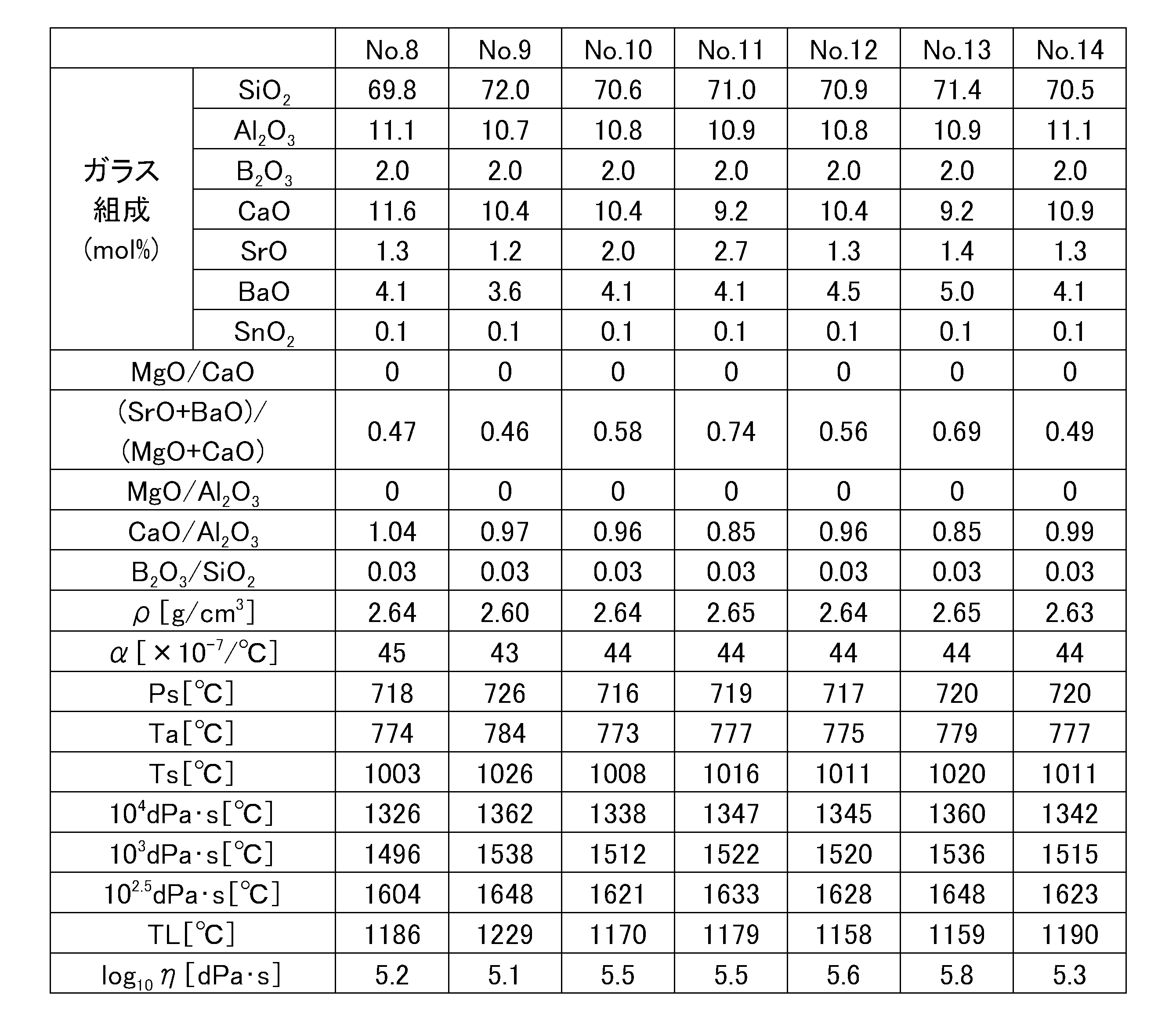
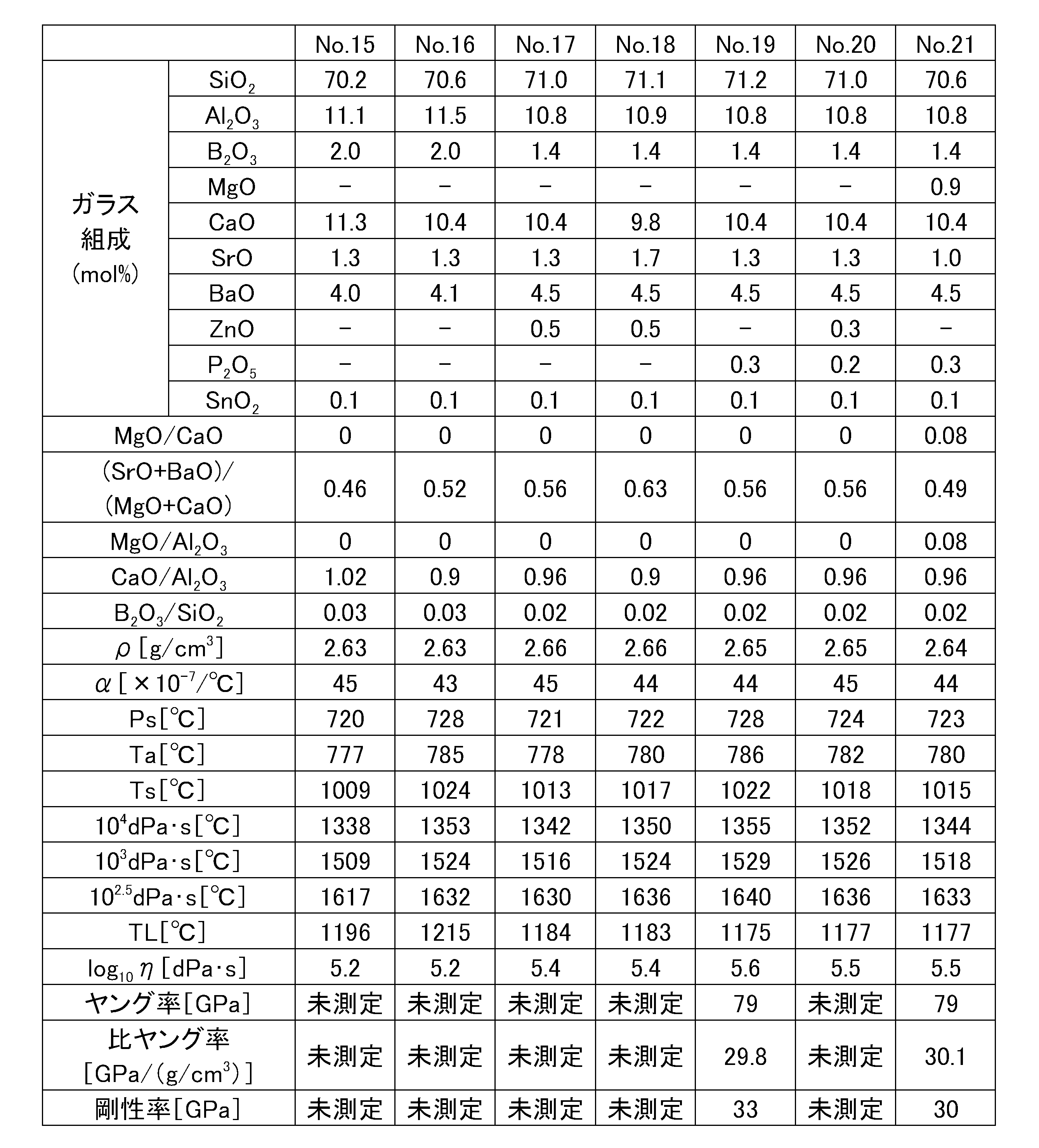
- Tables 1 to 5 show examples of the present invention (sample Nos. 1 to 35).
- Sample no. 1 to 35 were produced. First, a glass batch prepared so as to have the glass composition shown in the table was put in a platinum crucible, melted at 1600 ° C. for 24 hours, and then poured out onto a carbon plate to form a flat plate shape. Next, for each sample obtained, density ⁇ , thermal expansion coefficient ⁇ , strain point Ps, annealing point Ta, softening point Ts, temperature at 10 4 dPa ⁇ s, temperature at 10 3 dPa ⁇ s, 10 2. The temperature at 5 dPa ⁇ s, the liquidus temperature TL, the liquidus viscosity log 10 ⁇ TL, Young's modulus, specific Young's modulus, and rigidity were evaluated.
- the density ⁇ is a value measured by the well-known Archimedes method.
- the thermal expansion coefficient ⁇ is a value measured with a dilatometer, and is an average value in a temperature range of 30 to 380 ° C.
- Strain point Ps, annealing point Ta, and softening point Ts are values measured based on ASTM C336.
- the temperature at 10 4.0 dPa ⁇ s, the temperature at 10 3.0 dPa ⁇ s, and the temperature at 10 2.5 dPa ⁇ s are values measured by the platinum ball pulling method.
- the liquid phase temperature TL passes through a standard sieve 30 mesh (500 ⁇ m), and after the glass powder remaining in 50 mesh (300 ⁇ m) is placed in a platinum boat, the platinum boat is held in a temperature gradient furnace for 24 hours to obtain crystal It is the value which measured the temperature which deposits.
- the liquidus viscosity log 10 ⁇ TL is a value obtained by measuring the viscosity of the glass at the liquidus temperature TL by a platinum ball pulling method.
- the Young's modulus and rigidity are values measured by a well-known resonance method.
- the density ⁇ is 2.66 g / cm 3 or less
- the thermal expansion coefficient ⁇ is 38 to 46 ⁇ 10 ⁇ 7 / ° C.
- the strain point Ps is 712 ° C. or more.
- the temperature at 10 2.5 dPa ⁇ s is 1653 ° C. or less
- the liquidus temperature TL is 1229 ° C. or less
- the liquidus viscosity log 10 ⁇ TL is 4.7 or more
- the Young's modulus is 78 GPa or more
- the specific Young's modulus is 29.7 GPa / It was (g / cm 3 ) or more.
- sample no. Nos. 1 to 35 have good devitrification resistance, so that they can be easily formed to a plate thickness of 400 ⁇ m or less, and the specific Young's modulus is large, so that even when the plate thickness is 400 ⁇ m or less, the glass substrate is hardly bent. Therefore, sample no. 1 to 35 are considered to be suitable as glass substrates for liquid crystal lenses. Sample No. Although Nos. 1 to 35 did not contain As 2 O 3 or Sb 2 O 3 in the glass composition, they contained SnO 2 and had good foam quality.
- a glass substrate for a liquid crystal lens having a plate width of 1500 mm and a plate thickness of 250 ⁇ m was formed by an overflow down draw method.
- the surface roughness Ra of the glass substrate for liquid crystal lenses was 20 mm or less (see Tables 1 and 5).
- the liquid crystal lens is appropriately adjusted by adjusting the speed of the pulling roller, the speed of the cooling roller, the temperature distribution of the heating device, the temperature of the molten glass, the flow rate of the molten glass, the drawing speed, the rotation speed of the stirring stirrer, etc. The surface quality of the glass substrate was adjusted.
Landscapes
- Chemical & Material Sciences (AREA)
- Physics & Mathematics (AREA)
- Organic Chemistry (AREA)
- Chemical Kinetics & Catalysis (AREA)
- General Chemical & Material Sciences (AREA)
- Geochemistry & Mineralogy (AREA)
- Materials Engineering (AREA)
- Life Sciences & Earth Sciences (AREA)
- Engineering & Computer Science (AREA)
- Optics & Photonics (AREA)
- General Physics & Mathematics (AREA)
- Ceramic Engineering (AREA)
- Nonlinear Science (AREA)
- Mathematical Physics (AREA)
- Crystallography & Structural Chemistry (AREA)
- Glass Compositions (AREA)
Abstract
Description



Claims (13)
- ガラス組成として、mol%で、SiO2 45~75%、Al2O3 5~15%、B2O3 0~15%、MgO 0~15%、CaO 0~15%を含有し、且つ板厚が400μm以下であることを特徴とする液晶レンズ用ガラス基板。
- 比ヤング率が29GPa/(g/cm3)以上であることを特徴とする請求項1に記載の液晶レンズ用ガラス基板。
- 歪点が650℃以上であることを特徴とする請求項1又は2に記載の液晶レンズ用ガラス基板。
- 密度が2.7g/cm3以下であることを特徴とする請求項1~3の何れか一項に記載の液晶レンズ用ガラス基板。
- 102.5dPa・sにおける温度が1650℃以下であることを特徴とする請求項1~4の何れか一項に記載の液晶レンズ用ガラス基板。
- 液相粘度が104.0dPa・s以上であることを特徴とする請求項1~5の何れか一項に記載の液晶レンズ用ガラス基板。
- 30~380℃における熱膨張係数が30~50×10-7/℃であることを特徴とする請求項1~6の何れか一項に記載の液晶レンズ用ガラス基板。
- オーバーフローダウンドロー法で成形されてなることを特徴とする請求項1~7の何れか一項に記載の液晶レンズ用ガラス基板。
- ガラス組成として、mol%で、SiO2 45~75%、Al2O3 5~15%、B2O3 0~15%、MgO 0~15%、CaO 0~15%を含有し、モル比MgO/CaOが0~1.5、モル比(SrO+BaO)/(MgO+CaO)が0~1、モル比MgO/Al2O3が0~1、モル比CaO/Al2O3が0~3、モル比B2O3/SiO2が0~0.3であり、実質的にアルカリ金属酸化物、As2O3、Sb2O3、PbO、及びBi2O3を含有せず、比ヤング率が29GPa/(g/cm3)以上、30~380℃における熱膨張係数が30~50×10-7/℃、密度が2.6g/cm3以下、液相粘度が105.0dPa・s以上、幅寸法が500mm以上、長さ寸法が500mm以上、板厚が400μm以下であることを特徴とする液晶レンズ用ガラス基板。
- ガラス組成として、mol%で、SiO2 45~75%、Al2O3 5~15%、B2O3 0~15%、MgO 0~15%、CaO 0~15%を含有し、モル比MgO/CaOが0~1.5、モル比(SrO+BaO)/(MgO+CaO)が0~1、モル比MgO/Al2O3が0~1、モル比CaO/Al2O3が0~3、モル比B2O3/SiO2が0~0.3であり、実質的にアルカリ金属酸化物、As2O3、Sb2O3、PbO、及びBi2O3を含有せず、比ヤング率が29GPa/(g/cm3)以上、30~380℃における熱膨張係数が30~50×10-7/℃、密度が2.6g/cm3以下、液相粘度が105.0dPa・s以上、板厚が400μm以下であることを特徴とする液晶レンズ用ガラス基板。
- 請求項1~10の何れか一項に記載の液晶レンズ用ガラス基板を備えてなることを特徴とする液晶レンズ。
- 板厚が400μm以下であり、且つ比ヤング率が29GPa/(g/cm3)以上であることを特徴とするガラス基板。
- 液晶レンズに用いることを特徴とする請求項12に記載のガラス基板。
Priority Applications (3)
| Application Number | Priority Date | Filing Date | Title |
|---|---|---|---|
| KR1020137025912A KR20130138304A (ko) | 2011-04-25 | 2012-04-19 | 액정 렌즈용 유리 기판 |
| CN201280018365.6A CN103492333A (zh) | 2011-04-25 | 2012-04-19 | 液晶透镜用玻璃基板 |
| US14/113,681 US20140049708A1 (en) | 2011-04-25 | 2012-04-19 | Glass substrate for liquid crystal lens |
Applications Claiming Priority (2)
| Application Number | Priority Date | Filing Date | Title |
|---|---|---|---|
| JP2011-096695 | 2011-04-25 | ||
| JP2011096695 | 2011-04-25 |
Publications (1)
| Publication Number | Publication Date |
|---|---|
| WO2012147615A1 true WO2012147615A1 (ja) | 2012-11-01 |
Family
ID=47072136
Family Applications (1)
| Application Number | Title | Priority Date | Filing Date |
|---|---|---|---|
| PCT/JP2012/060594 Ceased WO2012147615A1 (ja) | 2011-04-25 | 2012-04-19 | 液晶レンズ用ガラス基板 |
Country Status (6)
| Country | Link |
|---|---|
| US (1) | US20140049708A1 (ja) |
| JP (1) | JP5935471B2 (ja) |
| KR (1) | KR20130138304A (ja) |
| CN (1) | CN103492333A (ja) |
| TW (1) | TWI583649B (ja) |
| WO (1) | WO2012147615A1 (ja) |
Cited By (4)
| Publication number | Priority date | Publication date | Assignee | Title |
|---|---|---|---|---|
| US20140335331A1 (en) * | 2013-05-09 | 2014-11-13 | Corning Incorporated | Alkali-free phosphoborosilicate glass |
| US9440878B2 (en) | 2013-02-28 | 2016-09-13 | Corning Incorporated | Fusion formable lithium aluminosilicate glass ceramic |
| US11168018B2 (en) | 2013-08-15 | 2021-11-09 | Corning Incorporated | Aluminoborosilicate glass substantially free of alkali oxides |
| USRE49307E1 (en) | 2013-08-15 | 2022-11-22 | Corning Incorporated | Alkali-doped and alkali-free boroaluminosilicate glass |
Families Citing this family (31)
| Publication number | Priority date | Publication date | Assignee | Title |
|---|---|---|---|---|
| TWI614227B (zh) | 2012-02-29 | 2018-02-11 | 康寧公司 | 低cte之無鹼硼鋁矽酸鹽玻璃組成物及包含其之玻璃物件 |
| JP6365826B2 (ja) * | 2013-07-11 | 2018-08-01 | 日本電気硝子株式会社 | ガラス |
| US10209419B2 (en) | 2013-09-17 | 2019-02-19 | Corning Incorporated | Broadband polarizer made using ion exchangeable fusion drawn glass sheets |
| JP7060915B2 (ja) * | 2014-12-12 | 2022-04-27 | 日本電気硝子株式会社 | 無アルカリガラス |
| JP7004488B2 (ja) * | 2015-03-10 | 2022-01-21 | 日本電気硝子株式会社 | ガラス基板 |
| CN113045197A (zh) * | 2015-04-03 | 2021-06-29 | 日本电气硝子株式会社 | 玻璃 |
| CN107406300A (zh) * | 2015-04-03 | 2017-11-28 | 日本电气硝子株式会社 | 玻璃 |
| EP3303236B1 (en) | 2015-06-02 | 2021-09-29 | Corning Incorporated | Laminated glass article with tinted layer |
| US10351466B2 (en) | 2015-06-02 | 2019-07-16 | Nippon Electric Glass Co., Ltd. | Glass |
| TWI714698B (zh) * | 2016-01-12 | 2021-01-01 | 日商日本電氣硝子股份有限公司 | 玻璃 |
| KR20220076536A (ko) | 2016-05-04 | 2022-06-08 | 코닝 인코포레이티드 | 알루미노실리케이트 색 유리 조성물 및 이를 포함하는 유리 제품 |
| WO2017204143A1 (ja) * | 2016-05-25 | 2017-11-30 | 旭硝子株式会社 | データ記憶媒体基板用ガラス、データ記憶媒体用ガラス基板および磁気ディスク |
| JP7044064B2 (ja) * | 2016-08-05 | 2022-03-30 | Agc株式会社 | 無アルカリガラス基板、積層基板、およびガラス基板の製造方法 |
| WO2018084100A1 (ja) * | 2016-11-02 | 2018-05-11 | 旭硝子株式会社 | 無アルカリガラスおよびその製造方法 |
| KR20190091437A (ko) * | 2016-12-20 | 2019-08-06 | 니폰 덴키 가라스 가부시키가이샤 | 유리 |
| JP6787872B2 (ja) * | 2017-11-28 | 2020-11-18 | 日本電気硝子株式会社 | 無アルカリガラス板 |
| JP6631942B2 (ja) * | 2017-11-28 | 2020-01-15 | 日本電気硝子株式会社 | 無アルカリガラス板 |
| JP7418947B2 (ja) * | 2018-01-31 | 2024-01-22 | 日本電気硝子株式会社 | ガラス |
| CN116813196A (zh) * | 2018-06-19 | 2023-09-29 | 康宁股份有限公司 | 高应变点且高杨氏模量玻璃 |
| KR102183706B1 (ko) | 2018-08-14 | 2020-11-27 | 주식회사 엘지화학 | 광학 디바이스 |
| JP7389400B2 (ja) * | 2018-10-15 | 2023-11-30 | 日本電気硝子株式会社 | 無アルカリガラス板 |
| JP7478340B2 (ja) * | 2018-10-17 | 2024-05-07 | 日本電気硝子株式会社 | 無アルカリガラス板 |
| US20220024806A1 (en) * | 2018-12-10 | 2022-01-27 | Nippon Electric Glass Co., Ltd. | Non-alkali glass |
| US11117828B2 (en) | 2019-01-18 | 2021-09-14 | Corning Incorporated | Low dielectric loss glasses for electronic devices |
| KR102809238B1 (ko) * | 2019-01-18 | 2025-05-16 | 코닝 인코포레이티드 | 전자 장치용 저 유전 손실 유리 |
| TW202545844A (zh) | 2019-02-07 | 2025-12-01 | 日商Agc股份有限公司 | 無鹼玻璃 |
| KR20250084982A (ko) * | 2019-02-07 | 2025-06-11 | 에이지씨 가부시키가이샤 | 무알칼리 유리 |
| CN113412244A (zh) | 2019-02-07 | 2021-09-17 | Agc株式会社 | 无碱玻璃 |
| JP7644405B2 (ja) * | 2020-06-18 | 2025-03-12 | 日本電気硝子株式会社 | 無アルカリガラス板 |
| CN117923791A (zh) * | 2023-12-18 | 2024-04-26 | 彩虹显示器件股份有限公司 | 一种低热收缩玻璃及其制备方法 |
| CN119461844A (zh) * | 2024-09-29 | 2025-02-18 | 彩虹显示器件股份有限公司 | 耐热稳定高析晶裕度的无碱硼铝硅酸盐玻璃及其制备方法 |
Citations (4)
| Publication number | Priority date | Publication date | Assignee | Title |
|---|---|---|---|---|
| JP2008197640A (ja) * | 2007-01-16 | 2008-08-28 | Asahi Glass Co Ltd | 光学素子および光ヘッド装置 |
| JP2009013049A (ja) * | 2007-06-08 | 2009-01-22 | Nippon Electric Glass Co Ltd | 無アルカリガラスおよび無アルカリガラス基板 |
| JP2009229963A (ja) * | 2008-03-25 | 2009-10-08 | Citizen Holdings Co Ltd | 液晶光学素子 |
| JP2010132532A (ja) * | 2008-10-01 | 2010-06-17 | Nippon Electric Glass Co Ltd | ガラスロール及びその製造方法 |
Family Cites Families (16)
| Publication number | Priority date | Publication date | Assignee | Title |
|---|---|---|---|---|
| JP2001348247A (ja) * | 2000-05-31 | 2001-12-18 | Asahi Glass Co Ltd | 無アルカリガラス |
| US6819044B2 (en) * | 2002-04-10 | 2004-11-16 | Tdk Corporation | Thin-film EL device and composite substrate |
| CN1764610A (zh) * | 2003-03-31 | 2006-04-26 | 旭硝子株式会社 | 无碱玻璃 |
| FR2856055B1 (fr) * | 2003-06-11 | 2007-06-08 | Saint Gobain Vetrotex | Fils de verre aptes a renforcer des matieres organiques et/ou inorganiques, composites les renfermant et composition utilisee |
| FR2879591B1 (fr) * | 2004-12-16 | 2007-02-09 | Saint Gobain Vetrotex | Fils de verre aptes a renforcer des matieres organiques et/ou inorganiques |
| CN102603184B (zh) * | 2005-06-28 | 2015-04-15 | 康宁股份有限公司 | 下拉法制造无碱玻璃板的方法 |
| WO2007095115A1 (en) * | 2006-02-10 | 2007-08-23 | Corning Incorporated | Glass compositions having high thermal and chemical stability and methods of making thereof |
| WO2007099488A1 (en) * | 2006-03-03 | 2007-09-07 | Koninklijke Philips Electronics N.V. | Autosterξoscopic display device using controllable liquid crystal lens array for 3d/2d mode switching |
| DE102006016256B4 (de) * | 2006-03-31 | 2013-12-12 | Schott Ag | Aluminoborosilikatglas und dessen Verwendung |
| CN102898023B (zh) * | 2006-05-25 | 2016-11-23 | 日本电气硝子株式会社 | 强化玻璃及其制造方法 |
| JP5359271B2 (ja) * | 2006-07-13 | 2013-12-04 | 旭硝子株式会社 | 無アルカリガラス基板及びその製造方法並びに液晶ディスプレイパネル |
| KR101351366B1 (ko) * | 2006-10-10 | 2014-01-14 | 니폰 덴키 가라스 가부시키가이샤 | 강화 유리 기판 |
| JP2008201654A (ja) * | 2007-02-23 | 2008-09-04 | Hitachi Ltd | 表示装置 |
| US7851318B2 (en) * | 2007-11-01 | 2010-12-14 | Semiconductor Energy Laboratory Co., Ltd. | Semiconductor substrate and method for manufacturing the same, and method for manufacturing semiconductor device |
| JP5327702B2 (ja) * | 2008-01-21 | 2013-10-30 | 日本電気硝子株式会社 | ガラス基板の製造方法 |
| EP2450319A4 (en) * | 2009-07-02 | 2015-01-28 | Asahi Glass Co Ltd | ALKALIFREE GLASS AND METHOD FOR THE PRODUCTION THEREOF |
-
2012
- 2012-04-16 JP JP2012092857A patent/JP5935471B2/ja active Active
- 2012-04-19 US US14/113,681 patent/US20140049708A1/en not_active Abandoned
- 2012-04-19 KR KR1020137025912A patent/KR20130138304A/ko not_active Ceased
- 2012-04-19 CN CN201280018365.6A patent/CN103492333A/zh active Pending
- 2012-04-19 WO PCT/JP2012/060594 patent/WO2012147615A1/ja not_active Ceased
- 2012-04-23 TW TW101114412A patent/TWI583649B/zh active
Patent Citations (4)
| Publication number | Priority date | Publication date | Assignee | Title |
|---|---|---|---|---|
| JP2008197640A (ja) * | 2007-01-16 | 2008-08-28 | Asahi Glass Co Ltd | 光学素子および光ヘッド装置 |
| JP2009013049A (ja) * | 2007-06-08 | 2009-01-22 | Nippon Electric Glass Co Ltd | 無アルカリガラスおよび無アルカリガラス基板 |
| JP2009229963A (ja) * | 2008-03-25 | 2009-10-08 | Citizen Holdings Co Ltd | 液晶光学素子 |
| JP2010132532A (ja) * | 2008-10-01 | 2010-06-17 | Nippon Electric Glass Co Ltd | ガラスロール及びその製造方法 |
Cited By (9)
| Publication number | Priority date | Publication date | Assignee | Title |
|---|---|---|---|---|
| US9440878B2 (en) | 2013-02-28 | 2016-09-13 | Corning Incorporated | Fusion formable lithium aluminosilicate glass ceramic |
| US9919953B2 (en) | 2013-02-28 | 2018-03-20 | Corning Incorporated | Fusion formable lithium aluminosilicate glass ceramic |
| US20140335331A1 (en) * | 2013-05-09 | 2014-11-13 | Corning Incorporated | Alkali-free phosphoborosilicate glass |
| CN105358497A (zh) * | 2013-05-09 | 2016-02-24 | 康宁股份有限公司 | 无碱的硼磷硅酸盐玻璃 |
| US9527767B2 (en) * | 2013-05-09 | 2016-12-27 | Corning Incorporated | Alkali-free phosphoborosilicate glass |
| CN105358497B (zh) * | 2013-05-09 | 2021-04-20 | 康宁股份有限公司 | 无碱的硼磷硅酸盐玻璃 |
| US11168018B2 (en) | 2013-08-15 | 2021-11-09 | Corning Incorporated | Aluminoborosilicate glass substantially free of alkali oxides |
| USRE49307E1 (en) | 2013-08-15 | 2022-11-22 | Corning Incorporated | Alkali-doped and alkali-free boroaluminosilicate glass |
| US12134580B2 (en) | 2013-08-15 | 2024-11-05 | Corning Incorporated | Aluminoborosilicate glass substantially free of alkali oxides |
Also Published As
| Publication number | Publication date |
|---|---|
| US20140049708A1 (en) | 2014-02-20 |
| KR20130138304A (ko) | 2013-12-18 |
| TW201247585A (en) | 2012-12-01 |
| CN103492333A (zh) | 2014-01-01 |
| JP2012236759A (ja) | 2012-12-06 |
| JP5935471B2 (ja) | 2016-06-15 |
| TWI583649B (zh) | 2017-05-21 |
Similar Documents
| Publication | Publication Date | Title |
|---|---|---|
| JP5935471B2 (ja) | 液晶レンズ | |
| JP7684641B2 (ja) | ガラス | |
| CN103168011B (zh) | 高折射率玻璃 | |
| JP6801651B2 (ja) | ガラス | |
| JP6365826B2 (ja) | ガラス | |
| JP5233998B2 (ja) | ガラス板およびその製造方法ならびにtftパネルの製造方法 | |
| KR101351112B1 (ko) | 플랫 패널 디스플레이용 유리 기판 및 그 제조 방법 | |
| JP5387411B2 (ja) | 基板用ガラス板 | |
| KR20230106745A (ko) | 유리 기판 | |
| JP2015180595A (ja) | ガラス板 | |
| CN104058589B (zh) | 高度折射的薄玻璃 | |
| TW201731787A (zh) | 平面面板顯示器用玻璃基板及其製造方法 | |
| TWI543953B (zh) | 無鹼玻璃 | |
| WO2015056645A1 (ja) | 無アルカリガラス | |
| WO2017002808A1 (ja) | ディスプレイ用ガラス基板およびその製造方法 | |
| JP5708484B2 (ja) | 基板用ガラス板 | |
| CN118084324A (zh) | 无碱玻璃板 | |
| KR20130057440A (ko) | 플랫 패널 디스플레이용 유리 기판 | |
| JP6354943B2 (ja) | ガラス | |
| TW202104119A (zh) | 包含磷與低離子場強度修飾劑之顯示組成物 | |
| JP2022539144A (ja) | 熱履歴の影響を受けにくい無アルカリガラス |
Legal Events
| Date | Code | Title | Description |
|---|---|---|---|
| 121 | Ep: the epo has been informed by wipo that ep was designated in this application |
Ref document number: 12776773 Country of ref document: EP Kind code of ref document: A1 |
|
| ENP | Entry into the national phase |
Ref document number: 20137025912 Country of ref document: KR Kind code of ref document: A |
|
| WWE | Wipo information: entry into national phase |
Ref document number: 14113681 Country of ref document: US |
|
| NENP | Non-entry into the national phase |
Ref country code: DE |
|
| 122 | Ep: pct application non-entry in european phase |
Ref document number: 12776773 Country of ref document: EP Kind code of ref document: A1 |