WO2012147457A1 - 車両用前照灯装置 - Google Patents
車両用前照灯装置 Download PDFInfo
- Publication number
- WO2012147457A1 WO2012147457A1 PCT/JP2012/058868 JP2012058868W WO2012147457A1 WO 2012147457 A1 WO2012147457 A1 WO 2012147457A1 JP 2012058868 W JP2012058868 W JP 2012058868W WO 2012147457 A1 WO2012147457 A1 WO 2012147457A1
- Authority
- WO
- WIPO (PCT)
- Prior art keywords
- target object
- irradiation range
- unit
- control unit
- passing
- Prior art date
- Legal status (The legal status is an assumption and is not a legal conclusion. Google has not performed a legal analysis and makes no representation as to the accuracy of the status listed.)
- Ceased
Links
Images


Classifications
-
- B—PERFORMING OPERATIONS; TRANSPORTING
- B60—VEHICLES IN GENERAL
- B60Q—ARRANGEMENT OF SIGNALLING OR LIGHTING DEVICES, THE MOUNTING OR SUPPORTING THEREOF OR CIRCUITS THEREFOR, FOR VEHICLES IN GENERAL
- B60Q1/00—Arrangement of optical signalling or lighting devices, the mounting or supporting thereof or circuits therefor
- B60Q1/02—Arrangement of optical signalling or lighting devices, the mounting or supporting thereof or circuits therefor the devices being primarily intended to illuminate the way ahead or to illuminate other areas of way or environments
- B60Q1/04—Arrangement of optical signalling or lighting devices, the mounting or supporting thereof or circuits therefor the devices being primarily intended to illuminate the way ahead or to illuminate other areas of way or environments the devices being headlights
- B60Q1/06—Arrangement of optical signalling or lighting devices, the mounting or supporting thereof or circuits therefor the devices being primarily intended to illuminate the way ahead or to illuminate other areas of way or environments the devices being headlights adjustable, e.g. remotely-controlled from inside vehicle
- B60Q1/08—Arrangement of optical signalling or lighting devices, the mounting or supporting thereof or circuits therefor the devices being primarily intended to illuminate the way ahead or to illuminate other areas of way or environments the devices being headlights adjustable, e.g. remotely-controlled from inside vehicle automatically
- B60Q1/085—Arrangement of optical signalling or lighting devices, the mounting or supporting thereof or circuits therefor the devices being primarily intended to illuminate the way ahead or to illuminate other areas of way or environments the devices being headlights adjustable, e.g. remotely-controlled from inside vehicle automatically due to special conditions, e.g. adverse weather, type of road, badly illuminated road signs or potential dangers
-
- B—PERFORMING OPERATIONS; TRANSPORTING
- B60—VEHICLES IN GENERAL
- B60Q—ARRANGEMENT OF SIGNALLING OR LIGHTING DEVICES, THE MOUNTING OR SUPPORTING THEREOF OR CIRCUITS THEREFOR, FOR VEHICLES IN GENERAL
- B60Q2300/00—Indexing codes for automatically adjustable headlamps or automatically dimmable headlamps
- B60Q2300/30—Indexing codes relating to the vehicle environment
- B60Q2300/33—Driving situation
- B60Q2300/338—Overtaking
-
- B—PERFORMING OPERATIONS; TRANSPORTING
- B60—VEHICLES IN GENERAL
- B60Q—ARRANGEMENT OF SIGNALLING OR LIGHTING DEVICES, THE MOUNTING OR SUPPORTING THEREOF OR CIRCUITS THEREFOR, FOR VEHICLES IN GENERAL
- B60Q2300/00—Indexing codes for automatically adjustable headlamps or automatically dimmable headlamps
- B60Q2300/40—Indexing codes relating to other road users or special conditions
- B60Q2300/45—Special conditions, e.g. pedestrians, road signs or potential dangers
Definitions
- the present invention relates to a vehicle headlamp device.
- a technique for controlling a light distribution pattern of a headlamp and irradiating it in an irradiation range suitable for a target object is disclosed (see Patent Document 1).
- the irradiation range is determined by the light distribution pattern. That is, controlling the light distribution pattern is equivalent to controlling the irradiation range.
- the vehicle headlamp device When the target object is detected by a recognition unit such as a camera, the vehicle headlamp device changes the light distribution pattern and irradiates the target object with a predetermined irradiation range set in advance. For example, when a vehicle headlamp device recognizes a pedestrian or a dangerous object during a high beam or an intermediate beam (a beam between a high beam and a low beam), an irradiation range (predetermined irradiation) that the pedestrian or dangerous object enters the irradiation range. Irradiate forward in the range). This makes it easier for the driver to visually recognize a pedestrian or a dangerous object.
- the driver performs passing (an operation for manually switching between a high beam and a low beam) while the irradiation range is controlled to the predetermined irradiation range, this is performed on the target object.
- the control state until is reset. That is, the irradiation range immediately after the passing operation is an irradiation range in a state where the target object is not recognized (detected). According to this, the visibility with respect to the target object immediately after passing operation will fall.
- the present invention has been made in view of such circumstances, and provides a vehicle headlamp device capable of ensuring the visibility of a target object immediately after a passing operation during irradiation range control. For the purpose.
- a first invention made to achieve the above object includes a headlamp that irradiates the front of a vehicle, a change unit that changes the irradiation range of the headlamp, and a recognition unit that recognizes the front of the vehicle.
- a control unit that detects a preset target object based on data output from the recognition unit and calculates a vertical position and a width direction position of the target object; and a control unit that controls the change unit And when the target object is detected, the control unit is configured to irradiate the target object with the irradiation range based on the analysis result of the analysis unit.
- a headlamp device for a vehicle that changes according to the control unit, and a storage unit that sequentially stores the irradiation range during the control operation of the target object, and a passing detection unit that detects a passing operation.
- the control unit comprises: When the passing operation is detected during the control operation on the target object, the irradiation range immediately after the passing operation is changed to the irradiation range stored in the storage unit immediately before the passing operation. To do.
- control unit sets the irradiation range based on the analysis result of the analysis unit such that at least a part of the target object falls within the irradiation range with respect to the target object.
- the predetermined irradiation range is changed. According to this structure, the visibility with respect to the target target object can be improved.
- control unit sets the irradiation range based on the analysis result of the analysis unit, and the predetermined irradiation is set such that the target object enters the irradiation range with respect to the target object. It is characterized by changing to the range. According to this configuration, the visibility with respect to the target object can be further improved.
- the fourth invention is characterized in that the recognition unit is a camera. According to this configuration, the target object can be detected simply and appropriately.
- a vehicle headlamp device 1 includes a headlamp 2, a light distribution changing unit 3, a camera 4, a passing detection unit 5, an electronic control unit (hereinafter referred to as an ECU). 6).
- the headlamp 2 includes a light source and a reflection plate (not shown), and a slit plate 21. As shown in FIG. 2, the headlamps 2 are installed at two locations on the front portion of the vehicle A, that is, one on each side of the front portion of the vehicle A.
- the slit plate 21 is disposed in front of the light source of each headlamp 2.
- the light distribution changing unit 3 (corresponding to a “changing unit”) is installed for each headlamp 2 and includes a drive motor 31, a leveling motor 32, and a swivel motor 33.
- the drive motor 31 drives the slit plate 21 based on a command from the ECU 6.
- the leveling motor 32 changes the optical axis of the headlamp 2 in the vertical direction based on a command from the ECU 6.
- the swivel motor 33 changes the optical axis of the headlamp 2 in the left-right direction based on a command from the ECU 6.
- the position where the light source of the headlamp 2 is covered is determined by the position of the slit plate 21, and a dark part (shadow) can be formed in the irradiation range by covering the light source.
- the light distribution pattern is determined by the combination of the vertical and horizontal angles (irradiation angle) of the optical axis, the position of the slit plate 21, and both headlamps 2.
- the irradiation range which the headlamp 2 irradiates is determined by a light distribution pattern. That is, the light distribution changing unit 3 changes the light distribution pattern by driving the optical axes of both the headlamps 2 and the slit plate 21 and changes the irradiation range of the headlamps 2.
- Camera 4 (corresponding to “recognition unit”) is an image sensor, and images the front of vehicle A. Infrared rays are used for imaging pedestrians and the like. The camera 4 is installed in the upper part of the vehicle A as shown in FIG. The camera 4 transmits the captured image data to the ECU 6.
- the passing detection unit 5 has a function of detecting a passing operation.
- the vehicle A is provided with operation levers (not shown) for various operations.
- the passing operation is performed by the driver performing a predetermined operation (for example, pulling forward to release the hand or pressing it to the back to release the hand).
- the passing detection unit 5 receives a signal from the operation lever and detects a predetermined operation of the operation lever.
- the passing detection unit 5 can detect the start of the passing operation (for example, the operation lever is pulled forward) and the end of the passing operation (for example, the operation lever is released to return to the original position).
- the passing detection unit 5 transmits detection information to the ECU 6.
- the passing detection unit 5 (passing detection function) may be mounted on the ECU 6.
- the ECU 6 is an electronic control unit that has a CPU and the like and controls the light distribution changing unit 3.
- the ECU 6 functionally includes an analysis unit 61, a control unit 62, and a storage unit 63.
- the analysis unit 61 is a well-known one and analyzes the imaging data of the camera 4.
- the analysis unit 61 detects a preset target object B based on the imaging data of the camera 4 and calculates the position of the target object B in the vertical direction and the vehicle width direction (left-right direction).
- the target object B is, for example, a pedestrian or an obstacle (triangular reflector or the like) shown in FIG.
- the analysis unit 61 may be a camera built-in type built in the camera 4.
- the control unit 62 has a function of controlling the light distribution changing unit 3.
- the control unit 62 changes the irradiation range to a predetermined irradiation range based on the analysis result of the analysis unit 61.
- the predetermined irradiation range is an irradiation range (light distribution pattern) set in advance for each target object.
- the predetermined irradiation range is a range corresponding to the position of the target object and changing by tracking the target object.
- the predetermined irradiation range is a range that actively includes the vicinity of the pedestrian's foot (lower body), or irradiation to the vicinity of the pedestrian's foot. Is a range in which (stronger) is set.
- the characteristic position (bright position) of the predetermined irradiation range changes. That is, the control unit 62 changes the irradiation range for the purpose of irradiating the target object. In the case of a pedestrian, dazzling of the pedestrian can be prevented by putting a part (foot) in the irradiation range.
- a plurality of target objects and corresponding predetermined irradiation ranges may be set. The operation of the control unit 62 for the passing operation will be described later.
- the storage unit 63 is a readable / writable storage device such as a RAM.
- the storage unit 63 continuously stores the controlled irradiation range (light distribution pattern) while the control unit 62 is controlling the irradiation range to the predetermined irradiation range. After storing for a predetermined time, the storage unit 63 erases the oldest data every time it is newly stored. That is, the storage unit 63 has a function of sequentially storing the irradiation range that changes every moment during the control to the predetermined irradiation range.
- the control unit 62 changes the irradiation range immediately after the passing operation to the irradiation range stored in the storage unit 63 immediately before the passing operation. change.
- the irradiation range immediately after the passing operation by the control unit 62 is not the irradiation range without the target object B, but the irradiation range irradiated immediately before the passing operation (predetermined irradiation range immediately before the passing operation).
- the control unit 62 performs the irradiation range in which the irradiation range is stored in the storage unit 63 during the period from the end of the passing operation to the recognition of the presence or absence of the target object B based on the information from the analysis unit 61.
- “immediately after the passing operation” is a period from the end of the passing operation until the ECU 6 recognizes the presence or absence of the target object B (if there is one).
- the control unit 62 controls to a predetermined irradiation range corresponding to the target object B.
- the control unit 62 controls the normal irradiation range (for example, manually selected). Change the exposure range.
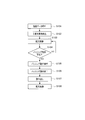
- the camera 4 transmits imaging data to the ECU 6, and the analysis unit 61 analyzes the imaging data (S101).
- the analysis unit 61 detects the target object B and calculates its position (S102).
- the control unit 62 controls the light distribution changing unit 3 so that the target object B is within a predetermined irradiation range (S103).
- the passing detection unit 5 detects the start of the passing operation in a state where the light distribution changing unit 3 is controlled (S104: Yes)
- the control unit 62 performs the passing operation according to the operation of the driver (S105).
- the storage unit 63 temporarily stops storing the irradiation range.
- the control unit 62 reads the irradiation range immediately before the passing operation from the storage unit 63 (S107). Almost simultaneously, the control unit 62 controls the light distribution changing unit 3 so that the read irradiation range (light distribution pattern) is obtained (S108). Thereafter, the presence / absence of the target object B is detected via the camera 4 and the analysis unit 61. When the target object B is present, it is changed to a predetermined irradiation range, and when there is no target object B, the target irradiation object B is changed to a normal irradiation range. The If a passing operation is not detected during the control to the predetermined irradiation range (S104: No), the control unit 62 continues to control the light distribution to the predetermined irradiation range (S103).
- the control unit 62 while the control unit 62 is controlling the predetermined irradiation range, the irradiation range is prevented from being changed to an irradiation range (normal irradiation range) in which there is no target object B immediately after the passing operation.
- the visibility to the target object B can be ensured by reproducing the irradiation range immediately before the passing operation.
- the target object B may be a bicycle on which a person is riding.
- the camera 4 is an example of a recognition unit that can recognize the front of the vehicle A, and the recognition unit may be a laser radar or the like.
- the headlamp 2 may not have the slit plate 21.
- the headlamp 2 and the light distribution changing unit 3 may be provided with a plurality of light sources on the left and right sides, or may determine the irradiation range based on the principle of the projector.
- Vehicle headlamp device 2 Headlamp 3: Light distribution change unit (change unit) 4: Camera (recognition unit) 5: Distance measuring unit 6: ECU 61: Analysis unit 62: Control unit 63: Storage unit A: Vehicle B: Target object
Landscapes
- Engineering & Computer Science (AREA)
- Mechanical Engineering (AREA)
- Lighting Device Outwards From Vehicle And Optical Signal (AREA)
Abstract
本発明の車両用前照灯装置は、目標対象物Bが検出された場合、制御部62が、解析部61の解析結果に基づいて、照射範囲を、目的対象物Bを照射する目的で、目的対象物Bに応じて変更する車両用前照灯装置であって、制御部62が目的対象物Bに対する制御作動中、当該照射範囲を記憶する記憶部63と、パッシング動作を検出するパッシング検出部5を備え、制御部62は、目的対象物Bに対する制御作動中、パッシング動作が検出された場合、パッシング動作直後の照射範囲を、パッシング動作直前に記憶部63に記憶された照射範囲に変更することを特徴とする。
Description
本発明は、車両用前照灯装置に関するものである。
車両用前照灯装置として、例えば前照灯の配光パターンを制御し、目標対象物に適した照射範囲で照射する技術が開示されている(特許文献1参照)。照射範囲は、配光パターンにより決定される。つまり、配光パターンを制御することは、照射範囲を制御することと同意である。
車両用前照灯装置は、カメラ等の認識部により目標対象物が検出された場合、配光パターンを変更して、目標対象物に対して予め設定された所定照射範囲に照射する。例えば、車両用前照灯装置は、ハイビームや中間ビーム(ハイビームとロービームの間のビーム)の際、歩行者または危険物を認識すると、歩行者または危険物が照射範囲に入る照射範囲(所定照射範囲)で前方を照射する。これにより、運転手は、歩行者または危険物をさらに視認しやすくなる。
しかしながら、上記車両用前照灯装置では、照射範囲が所定照射範囲に制御されている際、運転手がパッシング(ハイビームとロービームを瞬間的に手動で切り替える動作)を行うと、目的対象物に対するこれまでの制御状態がリセットされてしまう。つまり、パッシング動作直後の照射範囲は、目的対象物を認識(検出)していない状態の照射範囲となる。これによれば、パッシング動作直後の目的対象物に対する視認性が低下してしまう。
本発明は、このような事情に鑑みて為されたものであり、照射範囲制御中において、パッシング動作直後の目的対象物への視認性を確保することができる車両用前照灯装置を提供することを目的とする。
上記目的を達成するためになされた第1の発明は、車両の前方を照射する前照灯と、前記前照灯の照射範囲を変更する変更部と、前記車両の前方を認識する認識部と、前記認識部から出力されるデータに基づいて、予め設定された目標対象物を検出するとともに前記目標対象物の上下方向および幅方向の位置を算出する解析部と、前記変更部を制御する制御部と、を備え、前記目標対象物が検出された場合、前記制御部が、前記解析部の解析結果に基づいて、前記照射範囲を、前記目的対象物を照射する目的で、前記目的対象物に応じて変更する車両用前照灯装置であって、前記制御部が前記目的対象物に対する制御作動中、当該照射範囲を逐次記憶していく記憶部と、パッシング動作を検出するパッシング検出部を備え、前記制御部は、前記目的対象物に対する制御作動中、前記パッシング動作が検出された場合、前記パッシング動作直後の前記照射範囲を、前記パッシング動作直前に前記記憶部に記憶された前記照射範囲に変更することを特徴とする。
この構成によれば、照射範囲制御中、パッシング動作直後に、全く目的対象物がない状態の照射範囲に変更されることを防止でき、パッシング動作直前の照射範囲を再現することで、目的対象物に対する視認性を確保することができる。
第2の発明は、前記制御部が、前記解析部の解析結果に基づいて、前記照射範囲を、前記目的対象物に対して前記目標対象物の少なくとも一部が前記照射範囲に入るように設定された所定照射範囲に変更することを特徴とする。この構成によれば、目的対象物に対する視認性を向上させることができる。
第3の発明は、前記制御部が、前記解析部の解析結果に基づいて、前記照射範囲を、前記目的対象物に対して前記目標対象物が前記照射範囲に入るように設定された所定照射範囲に変更することを特徴とする。この構成によれば、目的対象物に対する視認性をさらに向上させることができる。
第4の発明は、前記認識部がカメラであることを特徴とする。この構成によれば、簡易かつ適切に目的対象物を検出することができる。
次に、好ましい実施形態を挙げ、図1~図3を参照して本発明をより詳しく説明する。本実施形態の車両用前照灯装置1は、図1に示すように、前照灯2と、配光変更部3と、カメラ4と、パッシング検出部5と、電子制御ユニット(以下、ECUと称する)6と、を備えている。
前照灯2は、図示しない光源および反射板と、スリット板21と、を備えている。前照灯2は、図2に示すように、車両A前部に2箇所、すなわち車両A前部の左右に1つずつ設置されている。スリット板21は、各前照灯2の光源の前方に配置されている。
配光変更部3(「変更部」に相当する)は、各前照灯2に対して設置されており、駆動モータ31、レベリングモータ32およびスイブルモータ33を備えている。駆動モータ31は、ECU6の指令に基づきスリット板21を駆動させる。レベリングモータ32は、ECU6の指令に基づき前照灯2の光軸を上下方向に変更する。スイブルモータ33は、ECU6の指令に基づき前照灯2の光軸を左右方向に変更する。
スリット板21の位置により、前照灯2の光源が覆われる部分が決まり、光源が覆われることで照射範囲に暗い部分(影)を形成することができる。配光パターンは、光軸の上下左右の角度(照射角度)、スリット板21の位置、および両前照灯2の組み合わせにより決定される。そして、配光パターンにより、前照灯2が照射する照射範囲が決定される。つまり、配光変更部3は、両前照灯2の光軸およびスリット板21を駆動することで配光パターンを変更し、前照灯2の照射範囲を変更する。
カメラ4(「認識部」に相当する)は、画像センサであって、車両A前方を撮像する。歩行者等の撮像には赤外線が用いられる。カメラ4は、図2に示すように、車両A上部に設置されている。カメラ4は、撮像した撮像データをECU6に送信する。
パッシング検出部5は、パッシング動作を検出する機能を有する。車両Aには、各種操作のための操作レバー(図示しない)が設置されている。パッシング動作は、運転手が操作レバーを所定操作(例えば手前に引いて手を放すまたは奥に押して手を放す)することで実施される。パッシング検出部5は、操作レバーから信号を受け、操作レバーの所定操作を検出する。パッシング検出部5は、パッシング動作の開始(例えば操作レバーが手前に引かれる)と、パッシング動作の終了(例えば操作レバーが放され元の位置に戻る)を検出できる。パッシング検出部5は、検出情報をECU6に送信する。なお、パッシング検出部5(パッシング検出機能)は、ECU6に搭載してもよい。
ECU6は、CPU等を有し、配光変更部3を制御するための電子制御ユニットである。ECU6は、機能的に、解析部61と、制御部62と、記憶部63と、を備えている。
解析部61は、公知のものであり、カメラ4の撮像データを解析する。解析部61は、カメラ4の撮像データに基づいて、予め設定された目標対象物Bを検出するとともに、目標対象物Bの上下方向および車両幅方向(左右方向)の位置を算出する。目標対象物Bとは、例えば、図2に示す歩行者や障害物(三角反射板等)である。解析部61は、カメラ4に内蔵されたカメラ内蔵型でもよい。
制御部62は、配光変更部3を制御する機能を有している。制御部62は、解析部61により目標対象物Bが検出された場合、解析部61の解析結果に基づいて、照射範囲を所定照射範囲に変更する。所定照射範囲とは、目標対象物ごとに予め設定された照射範囲(配光パターン)である。所定照射範囲は、目標対象物の位置に対応し、目標対象物を追跡して変化する範囲である。
例えば、図2に示すように、目標対象物Bが歩行者である場合、所定照射範囲は、歩行者の足付近(下半身)を積極的に含んだ範囲、あるいは歩行者の足付近への照射を強く(明るく)した範囲となる。撮像データ上の目的対象物の移動に伴って、所定照射範囲の上記特徴位置(明るい位置)は変化する。つまり、制御部62は、目的対象物を照射する目的で、照射範囲を変更する。歩行者の場合、一部(足元)を照射範囲に入れることで、歩行者の眩惑を防止できる。目標対象物および対応する所定照射範囲は、複数設定されていてもよい。パッシング動作に対する制御部62の動作については後述する。
記憶部63は、例えばRAMなどの読み書き可能な記憶装置である。記憶部63は、制御部62が照射範囲を所定照射範囲に制御中、制御された照射範囲(配光パターン)を継続的に記憶する。記憶部63は、所定時間記憶すると、その後は、新たに記憶するたびに最も古いデータを消去していく。つまり、記憶部63は、所定照射範囲に制御中、刻々と変化する照射範囲を逐次記憶していく機能を有する。
ここで、パッシング動作に対する制御部62の動作について説明する。制御部62は、照射範囲を所定照射範囲に制御中、パッシング検出部5によりパッシング動作が検出された場合、パッシング動作直後の照射範囲を、パッシング動作直前に記憶部63に記憶された照射範囲に変更する。つまり、制御部62により、パッシング動作直後の照射範囲は、目的対象物Bがない状態の照射範囲ではなく、パッシング動作直前に照射されていた照射範囲(パッシング動作直前の所定照射範囲)となる。
制御部62は、パッシング動作の終了から、解析部61からの情報により目的対象物Bの有無(有る場合はその位置)を認識するまでの期間、照射範囲を記憶部63に記憶された照射範囲に制御する。つまり、本実施形態において、パッシング動作直後とは、パッシング動作の終了からECU6が目的対象物Bの有無(有る場合はその位置)を認識するまでの期間である。制御部62は、パッシング動作後、目的対象物Bが検出された場合はそれに対応した所定照射範囲に制御し、目的対象物Bが検出されなかった場合は通常の照射範囲(例えば手動で選択された照射範囲)に変更する。
ここで、車両用前照灯装置1の動作フローを図3を参照して説明する。まず、カメラ4が撮像データをECU6に送信し、解析部61が撮像データを解析する(S101)。解析部61は、目標対象物Bを検出し、その位置を算出する(S102)。制御部62は、目標対象物Bに対して所定照射範囲となるように配光変更部3を制御する(S103)。この配光変更部3が制御された状態において、パッシング検出部5がパッシング動作の開始を検出すると(S104:Yes)、制御部62は、運転手の操作に応じてパッシング動作を実施する(S105)。パッシング動作が開始してから終了するまで、記憶部63は、照射範囲の記憶を一時停止する。
パッシング動作が終了すると(S106)、制御部62は、記憶部63からパッシング動作直前の照射範囲を読み出す(S107)。ほぼ同時に、制御部62は、読み出した照射範囲(配光パターン)となるように、配光変更部3を制御する(S108)。その後、カメラ4および解析部61を介して目標対象物Bの有無が検出され、目標対象物Bが有る場合は所定照射範囲に、目標対象物Bが無い場合は通常の照射範囲にそれぞれ変更される。なお、所定照射範囲に制御中、パッシング動作が検出されなければ(S104:No)、制御部62は、引き続き所定照射範囲に配光制御する(S103)。
本実施形態によれば、制御部62が所定照射範囲制御中において、パッシング動作直後に、全く目的対象物Bがない状態の照射範囲(通常の照射範囲)に照射範囲が変更されることを防止でき、パッシング動作直前の照射範囲を再現することで、目的対象物Bに対する視認性を確保することができる。
なお、本発明は、上記実施形態に限られない。例えば、目標対象物Bは、人が乗っている自転車等であってもよい。また、カメラ4は、車両A前方を認識可能な認識部の一例であって、認識部としてはレーザレーダ等であってもよい。また、前照灯2は、スリット板21を有しないものでもよい。例えば、前照灯2および配光変更部3は、左右のそれぞれに複数の光源を備えたものや、プロジェクタの原理により照射範囲を決定するもの等でもよい。
1:車両用前照灯装置
2:前照灯
3:配光変更部(変更部)
4:カメラ(認識部)
5:距離測定部
6:ECU
61:解析部
62:制御部
63:記憶部
A:車両
B:目標対象物
2:前照灯
3:配光変更部(変更部)
4:カメラ(認識部)
5:距離測定部
6:ECU
61:解析部
62:制御部
63:記憶部
A:車両
B:目標対象物
Claims (4)
- 車両の前方を照射する前照灯と、
前記前照灯の照射範囲を変更する変更部と、
前記車両の前方を認識する認識部と、
前記認識部から出力されるデータに基づいて、予め設定された目標対象物を検出するとともに前記目標対象物の上下方向および幅方向の位置を算出する解析部と、
前記変更部を制御する制御部と、
を備え、前記目標対象物が検出された場合、前記制御部が、前記解析部の解析結果に基づいて、前記照射範囲を、前記目的対象物を照射する目的で、前記目的対象物に応じて変更する車両用前照灯装置であって、
前記制御部が前記目的対象物に対する制御作動中、当該照射範囲を逐次記憶していく記憶部と、
パッシング動作を検出するパッシング検出部と、
を備え、
前記制御部は、前記目的対象物に対する制御作動中、前記パッシング動作が検出された場合、前記パッシング動作直後の前記照射範囲を、前記パッシング動作直前に前記記憶部に記憶された前記照射範囲に変更することを特徴とする車両用前照灯装置。 - 前記制御部は、前記解析部の解析結果に基づいて、前記照射範囲を、前記目的対象物に対して前記目標対象物の少なくとも一部が前記照射範囲に入るように設定された所定照射範囲に変更する請求項1に記載の車両用前照灯装置。
- 前記制御部は、前記解析部の解析結果に基づいて、前記照射範囲を、前記目的対象物に対して前記目標対象物が前記照射範囲に入るように設定された所定照射範囲に変更する請求項1に記載の車両用前照灯装置。
- 前記認識部は、カメラである請求項1~3の何れか一項に記載の車両用前照灯装置。
Applications Claiming Priority (2)
| Application Number | Priority Date | Filing Date | Title |
|---|---|---|---|
| JP2011101660A JP2012232643A (ja) | 2011-04-28 | 2011-04-28 | 車両用前照灯装置 |
| JP2011-101660 | 2011-04-28 |
Publications (1)
| Publication Number | Publication Date |
|---|---|
| WO2012147457A1 true WO2012147457A1 (ja) | 2012-11-01 |
Family
ID=47071982
Family Applications (1)
| Application Number | Title | Priority Date | Filing Date |
|---|---|---|---|
| PCT/JP2012/058868 Ceased WO2012147457A1 (ja) | 2011-04-28 | 2012-04-02 | 車両用前照灯装置 |
Country Status (2)
| Country | Link |
|---|---|
| JP (1) | JP2012232643A (ja) |
| WO (1) | WO2012147457A1 (ja) |
Cited By (1)
| Publication number | Priority date | Publication date | Assignee | Title |
|---|---|---|---|---|
| AT518039A1 (de) * | 2015-11-25 | 2017-06-15 | Zkw Group Gmbh | Kraftfahrzeugscheinwerfer mit einer intelligenten Autobahn-Lichthupe |
Families Citing this family (1)
| Publication number | Priority date | Publication date | Assignee | Title |
|---|---|---|---|---|
| JP6324808B2 (ja) * | 2014-05-23 | 2018-05-16 | スタンレー電気株式会社 | 車両用前照灯の制御装置、車両用前照灯システム |
Citations (2)
| Publication number | Priority date | Publication date | Assignee | Title |
|---|---|---|---|---|
| JP2000225888A (ja) * | 1999-02-02 | 2000-08-15 | Mazda Motor Corp | 車両の前照灯制御装置 |
| JP2011016504A (ja) * | 2009-07-10 | 2011-01-27 | Koito Mfg Co Ltd | 車両用前照灯装置 |
-
2011
- 2011-04-28 JP JP2011101660A patent/JP2012232643A/ja not_active Withdrawn
-
2012
- 2012-04-02 WO PCT/JP2012/058868 patent/WO2012147457A1/ja not_active Ceased
Patent Citations (2)
| Publication number | Priority date | Publication date | Assignee | Title |
|---|---|---|---|---|
| JP2000225888A (ja) * | 1999-02-02 | 2000-08-15 | Mazda Motor Corp | 車両の前照灯制御装置 |
| JP2011016504A (ja) * | 2009-07-10 | 2011-01-27 | Koito Mfg Co Ltd | 車両用前照灯装置 |
Cited By (3)
| Publication number | Priority date | Publication date | Assignee | Title |
|---|---|---|---|---|
| AT518039A1 (de) * | 2015-11-25 | 2017-06-15 | Zkw Group Gmbh | Kraftfahrzeugscheinwerfer mit einer intelligenten Autobahn-Lichthupe |
| AT518039B1 (de) * | 2015-11-25 | 2018-02-15 | Zkw Group Gmbh | Kraftfahrzeugscheinwerfer mit einer intelligenten Autobahn-Lichthupe |
| US10864847B2 (en) | 2015-11-25 | 2020-12-15 | Zkw Group Gmbh | Motor vehicle headlight with an intelligent motorway flasher |
Also Published As
| Publication number | Publication date |
|---|---|
| JP2012232643A (ja) | 2012-11-29 |
Similar Documents
| Publication | Publication Date | Title |
|---|---|---|
| US10618458B2 (en) | Vehicle headlight control device | |
| JP4660501B2 (ja) | 車両のヘッドライトの光の広がりの制御 | |
| JP6963563B2 (ja) | 車両用照明システムおよび車両 | |
| JP6723290B2 (ja) | 車両用ヘッドランプシステムおよびその制御方法 | |
| JP2008226140A (ja) | 車両の運転支援装置 | |
| JP2013098169A (ja) | スポットランプユニット、このスポットランプユニットが備えられたヘッドライトシステム、およびこれを利用した前方照明方法 | |
| JP2012228978A (ja) | 車両用前照灯装置 | |
| KR101172954B1 (ko) | 차량등 자동제어 장치 및 방법 | |
| CN103303190A (zh) | 照射光控制装置 | |
| JP2013109911A (ja) | 照明装置 | |
| KR20130052425A (ko) | 헤드램프 시스템 | |
| JP2014106200A (ja) | 周辺監視装置及び駐車支援装置 | |
| JP2013252796A (ja) | 車両用前照灯の点灯制御装置、車両用前照灯システム | |
| JP6269380B2 (ja) | 車両の距離計測装置 | |
| JP6288208B1 (ja) | 車両用ヘッドライト制御装置 | |
| JP5934612B2 (ja) | 車両用前照灯の点灯制御装置、車両用前照灯システム | |
| US20140198514A1 (en) | Spotlight for a motor vehicle | |
| WO2012147457A1 (ja) | 車両用前照灯装置 | |
| JP2013043617A (ja) | 車両用前照灯の点灯制御装置、車両用前照灯システム | |
| JP5873372B2 (ja) | ヘッドライトの配光制御装置 | |
| JP6068070B2 (ja) | 車両用前照灯の点灯制御装置、車両用前照灯システム | |
| KR20130045004A (ko) | 카메라를 이용한 에이밍 장치 및 그 방법 | |
| JP6409847B2 (ja) | 車両用ヘッドライト制御装置 | |
| JP2020020709A (ja) | センサシステム | |
| JP2013101432A (ja) | 障害物検出装置及びプログラム |
Legal Events
| Date | Code | Title | Description |
|---|---|---|---|
| 121 | Ep: the epo has been informed by wipo that ep was designated in this application |
Ref document number: 12776291 Country of ref document: EP Kind code of ref document: A1 |
|
| NENP | Non-entry into the national phase |
Ref country code: DE |
|
| 122 | Ep: pct application non-entry in european phase |
Ref document number: 12776291 Country of ref document: EP Kind code of ref document: A1 |