WO2012147201A1 - 建設機械の回転装置 - Google Patents
建設機械の回転装置 Download PDFInfo
- Publication number
- WO2012147201A1 WO2012147201A1 PCT/JP2011/060440 JP2011060440W WO2012147201A1 WO 2012147201 A1 WO2012147201 A1 WO 2012147201A1 JP 2011060440 W JP2011060440 W JP 2011060440W WO 2012147201 A1 WO2012147201 A1 WO 2012147201A1
- Authority
- WO
- WIPO (PCT)
- Prior art keywords
- roller
- hole
- plug
- ventilation member
- lubricating oil
- Prior art date
- Legal status (The legal status is an assumption and is not a legal conclusion. Google has not performed a legal analysis and makes no representation as to the accuracy of the status listed.)
- Ceased
Links
Images




Classifications
-
- B—PERFORMING OPERATIONS; TRANSPORTING
- B62—LAND VEHICLES FOR TRAVELLING OTHERWISE THAN ON RAILS
- B62D—MOTOR VEHICLES; TRAILERS
- B62D55/00—Endless track vehicles
- B62D55/08—Endless track units; Parts thereof
- B62D55/14—Arrangement, location, or adaptation of rollers
- B62D55/15—Mounting devices, e.g. bushings, axles, bearings, sealings
-
- B—PERFORMING OPERATIONS; TRANSPORTING
- B62—LAND VEHICLES FOR TRAVELLING OTHERWISE THAN ON RAILS
- B62D—MOTOR VEHICLES; TRAILERS
- B62D55/00—Endless track vehicles
- B62D55/06—Endless track vehicles with tracks without ground wheels
- B62D55/065—Multi-track vehicles, i.e. more than two tracks
- B62D55/0655—Articulated endless track vehicles
-
- B—PERFORMING OPERATIONS; TRANSPORTING
- B62—LAND VEHICLES FOR TRAVELLING OTHERWISE THAN ON RAILS
- B62D—MOTOR VEHICLES; TRAILERS
- B62D55/00—Endless track vehicles
- B62D55/08—Endless track units; Parts thereof
- B62D55/088—Endless track units; Parts thereof with means to exclude or remove foreign matter, e.g. sealing means, self-cleaning track links or sprockets, deflector plates or scrapers
-
- B—PERFORMING OPERATIONS; TRANSPORTING
- B62—LAND VEHICLES FOR TRAVELLING OTHERWISE THAN ON RAILS
- B62D—MOTOR VEHICLES; TRAILERS
- B62D55/00—Endless track vehicles
- B62D55/08—Endless track units; Parts thereof
- B62D55/092—Endless track units; Parts thereof with lubrication means
-
- B—PERFORMING OPERATIONS; TRANSPORTING
- B62—LAND VEHICLES FOR TRAVELLING OTHERWISE THAN ON RAILS
- B62D—MOTOR VEHICLES; TRAILERS
- B62D55/00—Endless track vehicles
- B62D55/08—Endless track units; Parts thereof
- B62D55/10—Bogies; Frames
-
- F—MECHANICAL ENGINEERING; LIGHTING; HEATING; WEAPONS; BLASTING
- F16—ENGINEERING ELEMENTS AND UNITS; GENERAL MEASURES FOR PRODUCING AND MAINTAINING EFFECTIVE FUNCTIONING OF MACHINES OR INSTALLATIONS; THERMAL INSULATION IN GENERAL
- F16K—VALVES; TAPS; COCKS; ACTUATING-FLOATS; DEVICES FOR VENTING OR AERATING
- F16K24/00—Devices, e.g. valves, for venting or aerating enclosures
-
- F—MECHANICAL ENGINEERING; LIGHTING; HEATING; WEAPONS; BLASTING
- F16—ENGINEERING ELEMENTS AND UNITS; GENERAL MEASURES FOR PRODUCING AND MAINTAINING EFFECTIVE FUNCTIONING OF MACHINES OR INSTALLATIONS; THERMAL INSULATION IN GENERAL
- F16K—VALVES; TAPS; COCKS; ACTUATING-FLOATS; DEVICES FOR VENTING OR AERATING
- F16K24/00—Devices, e.g. valves, for venting or aerating enclosures
- F16K24/02—Devices, e.g. valves, for venting or aerating enclosures the enclosure being itself a valve, tap, or cock
Definitions
- the present invention relates to a crawler guide roller, a traveling device, a rotating device such as an idler wheel used in construction machines such as a hydraulic excavator and a wheel loader.
- a lower traveling body of a tracked vehicle such as a hydraulic excavator includes a track frame having left and right side frames, a traveling device provided on one end side of each side frame, and an idler wheel provided on the other end side ( Idler), a crawler belt wound around the drive wheel (sprocket) and idler wheel of the traveling device, and guides the crawler belt toward the drive wheel and idler wheel, and a lower crawler belt guide roller.
- the traveling device, idler wheel, crawler belt guide roller, and the like described above constitute a rotating device of the construction machine.
- the crawler belt guide roller is usually fixed to the side frame and provided with a shaft support member (fixed body) in which a bottomed seal housing portion is formed, a support shaft fixed to the shaft support member, The support shaft is rotatably supported via a bush (slide bearing), and a bottomed seal housing portion is formed facing the seal housing portion of the shaft support member with a gap, and lubricating oil is stored therein.
- the roller (rotary body) and the floating seal that is disposed in the seal accommodating portion of the shaft support member and the seal accommodating portion of the roller and closes the gap between the two are roughly configured.
- the floating seal includes a pair of cylindrical seal rings having seal surfaces that are in sliding contact with each other, between one seal ring and the seal accommodating portion of the shaft support member, and between the other seal ring and the roller. And a pair of O-rings sandwiched between the two parts.
- Floating seals such as bearings that support rollers by constantly pressing each seal ring by the elastic force of the O-ring and bringing the seal surfaces into sliding contact with each other when the rollers rotate with respect to the shaft support member Is used to seal the lubricating oil supplied to the inside of the roller (Japanese Patent Laid-Open No. 2001-80550).
- the pressure becomes uneven between the inside and outside of the roller, and the air outside the roller (outside air) slides between the seal surface of one seal ring and the seal surface of the other seal ring. It flows into the roller through the surface. At this time, foreign matter such as rain water and muddy water collected in the muddy area, dust floating around the roller, etc., enters the roller together with the outside air, or adheres to the seal surface of each seal ring. .
- An object of the present invention is to provide a rotating device for a construction machine.
- the present invention provides a fixed body that is fixed to a vehicle body of a construction machine, a rotating body that is rotatably provided with respect to the fixed body, and stores lubricating oil therein, and Construction comprising a floating seal that closes a gap between the fixed body and the rotating body, seals lubricating oil stored inside the rotating body, and prevents rainwater and dust from entering from the outside. Applicable to mechanical rotating device.
- a feature of the configuration employed by the present invention is that air and / or water vapor are circulated between the inside and outside of the rotating body and lubricating oil and / or rainwater and dust are prevented from flowing through the rotating body. This is because a vent plug is provided.
- air and water vapor can be circulated between the inside and outside of the rotating body by the vent plug provided on the rotating body, and foreign matter (solid) such as dust, lubricating oil and rainwater ( Distribution of the liquid) can be prevented.
- foreign matter solid
- this volume expanded air By discharging the air to the outside of the rotating body through the vent plug, the pressure balance can be maintained between the inside and the outside of the rotating body.
- the vent plug is detachably attached to the rotating body and provided with a communication hole that communicates between the inside and the outside of the rotating body, and the ventilation plug is disposed in the communication hole of the plug body.
- a ventilation member that allows the flow of air and / or water vapor and prevents the flow of lubricating oil and / or rainwater and dust.
- air and water vapor are circulated between the inside and outside of the rotating body through the ventilation member simply by installing the ventilation member in the communication hole provided in the plug body and attaching the plug body to the rotation body. Can be made. Thereby, an appropriate pressure balance can always be maintained between the inside and the outside of the rotating body, and the sealing performance of the floating seal can be kept good.
- the present invention lies in that the ventilation member is formed using an open-cell porous material. Thereby, according to the size of the small hole of the porous material, it is possible to circulate a gas such as water vapor or air while preventing a liquid such as lubricating oil or rainwater from flowing through and a solid such as dust. . As a result, it is possible to suppress the pressure difference between the inside and the outside of the rotating body, and reliably prevent the leakage of lubricating oil and the entry of foreign matter into the seal surface of the floating seal due to this pressure difference. it can.
- the ventilation member is formed using an open-celled porous material made of any one material selected from the group consisting of ethylene tetrafluoride resin, polyimide resin, and ceramic material.
- a gas such as water vapor or air is circulated while preventing a liquid such as lubricating oil or rainwater and a solid such as dust from flowing. It is possible to suppress a pressure difference between the inside and the outside.
- the present invention resides in that the diameter of each small hole constituting the ventilation member is set in a range of 0.1 ⁇ m or more and 10 ⁇ m or less. Thereby, only gas can be distribute
- the present invention resides in that the diameter of each small hole constituting the ventilation member is set in a range of 0.15 ⁇ m or more and 0.3 ⁇ m or less. Thereby, only gas can be smoothly distribute
- FIG. 2 is an enlarged cross-sectional view of an upper crawler belt guide roller as seen from the direction of arrows II-II in FIG.
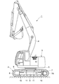
- FIG. 1 to 5 show a first embodiment of the present invention, and in this embodiment, an upper crawler belt guide roller of a hydraulic excavator is illustrated as a rotating device.
- reference numeral 1 denotes a hydraulic excavator as a typical example of a construction machine, and a vehicle body of the hydraulic excavator 1 is mounted on a self-propelled track-type lower traveling body 2 and can be turned on the lower traveling body 2.
- the upper revolving body 3 is generally constituted.
- a work device 4 is attached to the front side of the upper swing body 3 so as to be able to move up and down, and excavation work or the like is performed using the work device 4.
- the track frame 5 is a track frame constituting the lower traveling body 2, and the track frame 5 has left and right side frames 6 extending in the front and rear directions (only the left side is shown).
- a traveling device 7 is provided on one end side in the length direction of the side frame 6, and an idler wheel 8 is provided on the other end side in the length direction of the side frame 6.
- Reference numeral 9 denotes a crawler belt wound between the drive wheel 7A and the idler wheel 8 of the traveling device 7.
- the crawler belt 9 is driven by the drive wheel 7A, so that each lower crawler belt guide roller 10, which will be described later, While being guided by the crawler belt guide roller 11, the lower traveling body 2 is caused to travel around the drive wheel 7A and the idler wheel 8.
- Reference numeral 10 denotes a plurality of lower crawler belt guide rollers rotatably provided on the lower end side of the side frame 6, and each lower crawler belt guide roller 10 has an appropriate interval in the length direction (front and rear directions) of the side frame 6. It is arranged with.
- each lower crawler belt guide roller 10 guides the crawler belt 8 that rotates around the drive wheels 7 ⁇ / b> A and the idle wheels 8.
- Reference numeral 11 denotes two upper crawler belt guide rollers rotatably provided on the upper end side of the side frame 6.
- Each upper crawler belt guide roller 11 supports the crawler belt 9 from the lower side by supporting the crawler belt 9 from a traveling device. 7 toward the drive wheel 7A and the idler wheel 8.
- the upper crawler belt guide roller 11 includes a mounting bracket 12, a support shaft 14, a roller 15, a floating seal 23, a vent plug 31 and the like which will be described later.
- the mounting bracket 12 denotes a mounting bracket as a fixed body provided on the upper surface of the side frame 6, and this mounting bracket 12 is for mounting a support shaft 14 to be described later.
- the mounting bracket 12 includes a mounting board 12A fastened with a bolt 13 to a mounting seat 6A welded to the upper surface of the side frame 6, and an upper surface of the side frame 6 provided integrally with the mounting board 12A.
- the cylinder portion 12B protrudes in the left and right directions.
- the inner peripheral side of the cylindrical portion 12B is a shaft insertion hole 12C into which the support shaft 14 is inserted.
- a seal mounting hole 12D having a larger diameter than the shaft insertion hole 12C is formed at the protruding end of the cylindrical portion 12B concentrically with the shaft insertion hole 12C in a state opened to the outside.
- a floating seal 23 described later is attached to the hole 12D.
- the support shaft 14 is a support shaft fixed to the side frame 6 via the mounting bracket 12, and the support shaft 14 rotatably supports a roller 15 described later with respect to the side frame 6.
- one end side (base end side) of the support shaft 14 is inserted into the shaft insertion hole 12C of the mounting bracket 12 in a press-fit state, and the other end side (tip end side) of the support shaft 14 is a free end. And protrudes left and right from the cylindrical portion 12B of the mounting bracket 12.
- Reference numeral 15 denotes a roller as a rotating body rotatably attached to the front end side of the support shaft 14, and the roller 15 is generally constituted by a roller main body 16 formed in a stepped cylindrical shape and a lid body 17 described later.
- a roller main body 16 formed in a stepped cylindrical shape and a lid body 17 described later.
- a pair of crawler belt contact surfaces 16A that are located on both ends in the axial direction and contact the crawler belt 9, and projecting annularly from the respective crawler belt contact surfaces 16A over the entire circumference.
- a pair of flanges 16B are provided integrally.
- Bushing insertion holes 16C into which bushes 19 to be described later are inserted are provided on the inner peripheral side located at the axial center of the roller body 16, and the axial ends of the bushing insertion holes 16C are provided at both ends in the axial direction.
- Inner peripheral end surfaces 16D and 16E are provided.
- a plurality of small-diameter axial oil passages 16F are formed on the inner peripheral side of the roller main body 16 so as to surround the bushing insertion holes 16C and extend in the axial direction. Openings are made in the inner peripheral end faces 16D and 16E.
- a seal mounting having a hole diameter larger than the bush insertion hole 16C is mounted.
- the seal mounting hole 16G and the bracket accommodation hole 16H are formed concentrically with the bush insertion hole 16C.
- a thrust plate accommodation hole 16J having a larger diameter than the bush insertion hole 16C is formed concentrically with the bush insertion hole 16C on the inner peripheral side located on the other end side in the axial direction of the roller body 16.
- the thrust plate accommodation hole 16J is configured to be covered by a lid 17 described later in a state where a thrust plate 20 described later is accommodated.
- Reference numeral 17 denotes a lid attached to the other end side of the roller body 16 in the axial direction.
- the lid 17 includes a cylindrical portion 17A fitted into the thrust plate accommodation hole 16J of the roller body 16, and a cylindrical portion 17A.
- the flange portion 17B has a diameter that extends from the outer end surface over the entire circumference and is fixed to the end surface of the roller body 16 using bolts.
- This lid 17 seals the lubricating oil L in the roller 15 in cooperation with the floating seal 23 described later.
- the outer peripheral surface of the cylindrical portion 17A and the inner peripheral surface of the thrust plate accommodation hole 16J of the roller body 16 Is sealed liquid-tightly by an O-ring 18.
- a plurality of radial oil passages 17 ⁇ / b> C formed by cutting out the distal end portion in the radial direction is provided at the distal end portion of the cylindrical portion 17 ⁇ / b> A. Furthermore, a female screw hole 17D penetrating in the axial direction is screwed at the center of the flange portion 17B constituting the lid body 17, and a vent plug 31 described later is attached to the female screw hole 17D. .
- Reference numeral 19 denotes a bush inserted into the bush insertion hole 16C of the roller body 16.
- the bush 19 is inserted into the bush insertion hole 16C on the outer peripheral side, and the support shaft 14 is slidably inserted into the inner peripheral side.
- the cylindrical portion 19 ⁇ / b> A and the flange portion 19 ⁇ / b> B that expands from the one end portion of the cylindrical portion 19 ⁇ / b> A over the entire circumference and contacts the inner peripheral end surface 16 ⁇ / b> E of the roller body 16.
- the flange portion 19 ⁇ / b> B of the bush 19 is in sliding contact with a later-described thrust plate 20.
- Reference numeral 20 denotes a thrust plate accommodated in the thrust plate accommodating hole 16J of the roller body 16, and the thrust plate 20 has a disk shape having an outer diameter dimension substantially equal to the outer diameter dimension of the flange portion 19B constituting the bush 19. And is fixed to the end face on the front end side of the support shaft 14 using bolts 21.
- the thrust plate 20 is in contact with the flange portion 19 ⁇ / b> B of the bush 19 and is in contact with the distal end portion of the cylindrical portion 17 ⁇ / b> A of the lid body 17.
- the thrust plate 20 is configured to receive a thrust load acting on the roller 15 and prevent the roller 15 from being pulled out in the axial direction with respect to the support shaft 14.
- Reference numeral 22 denotes an oil sump chamber located between the lid 17 of the roller 15 and the thrust plate 20 and provided on the inner peripheral side of the roller 15 (roller body 16).
- the oil sump chamber 22 contains the lubricating oil L. It is what is stored.
- the lubricating oil L stored in the oil sump chamber 22 passes through the radial oil passage 17 ⁇ / b> C formed in the lid body 17 and the axial oil passage 16 ⁇ / b> F formed in the roller main body 16.
- the sliding surface is guided to the sliding surface with the cylindrical portion 19A, the sliding surface between the thrust plate 20 and the flange portion 19B of the bush 19, and the sliding surfaces are lubricated.
- reference numeral 23 denotes a floating seal provided between the cylindrical portion 12B of the mounting bracket 12 and the roller body 16 of the roller 15.
- the floating seal 23 closes the gap between the cylindrical portion 12B and the roller 15, seals the lubricating oil L stored in the oil sump chamber 22 in the roller 15, and removes foreign matter such as muddy water and earth and sand from the roller. 15 to prevent entry into the inside.
- the floating seal 23 includes a fixed-side seal ring 24 mounted on the inner peripheral side of the seal mounting hole 12D of the cylindrical portion 12B, and a rotation-side seal mounted on the inner peripheral side of the seal mounting hole 16G of the roller body 16.
- a pair of O-rings 26 provided between the ring 25 and the inner peripheral surface of the seal mounting hole 12D and the fixed-side seal ring 24 and between the inner peripheral surface of the seal mounting hole 16G and the rotary-side seal ring 25, respectively. , 27.
- the fixed-side seal ring 24 and the rotary-side seal ring 25 are formed in a cylindrical shape using cast iron or the like containing a material excellent in wear resistance and corrosion resistance.
- the shafts of the fixed-side seal ring 24 and the rotary-side seal ring 25 are Annular seal surfaces 24A and 25A are formed on the direction end surfaces, respectively.
- the O-rings 26 and 27 are formed of a strong elastic body such as butadiene rubber, and the fixed-side seal ring 24 and the rotation-side seal ring 25 are always pressed in the axial direction by the elastic force of the O-rings 26 and 27. In this state, the seal surfaces 24A and 25A are in sliding contact with each other.
- the floating seal 23 closes the gap between the rotating roller 15 and the mounting bracket 12, seals the lubricating oil L stored in the oil sump chamber 22 in the roller 15, rainwater, dust, etc. Is prevented from entering the roller 15.
- the sealing surface 24 ⁇ / b> A of the fixed-side seal ring 24 and the sealing surface 25 ⁇ / b> A of the rotation-side seal ring 25 are lubricated by the lubricating oil L sealed in the roller 15.
- vent plug used in the first embodiment will be described.
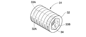
- Reference numeral 31 denotes a vent plug provided on the lid 17 of the roller 15.
- the vent plug 31 has air and / or water vapor (gas) between the oil sump chamber 22 formed in the roller 15 and the outside. It is allowed to circulate and prevent the lubricating oil and / or rainwater (liquid) and dust (solid) from circulating.
- the vent plug 31 includes a plug body 32 and a vent member 34 which will be described later.
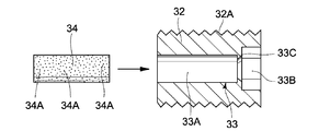
- plug body 32 is a plug body that forms an outer shell of the vent plug 31, and the plug body 32 is formed in a hollow cylindrical shape as a whole.
- a male screw part 32A is screwed on the outer peripheral side of the plug body 32, and the male screw part 32A is screwed into the female screw hole 17D of the lid body 17 so that the plug body 32 is detachably attached to the roller 15. It has become.
- a communication hole 33 described later is formed on the inner peripheral side of the plug body 32.
- the communication hole 33 is a communication hole provided on the inner peripheral side of the plug main body 32.
- the communication hole 33 is provided through the plug main body 32 in the axial direction.
- the inside of 15 is communicated with the outside.
- the communication hole 33 has a small-diameter hole portion 33A that accommodates a ventilation member 34, which will be described later, and a larger diameter than the small-diameter hole 33A, and a tightening tool (not shown) such as a hexagon wrench is engaged therewith. It is comprised by the hexagonal hole part 33B.
- One end side of the small-diameter hole portion 33A opens to the hexagonal hole portion 33B, and the other end side of the small-diameter hole portion 33A opens to the end surface in the axial direction of the plug body 32.
- one end side caulking portion 33C in which the small diameter hole portion 33A is reduced in diameter is formed on one end side of the small diameter hole portion 33A, and the small diameter hole portion 33A is also reduced in diameter on the other end side of the small diameter hole portion 33A.
- the other end side caulking portion 33D is formed.
- Reference numeral 34 denotes a ventilation member disposed in the communication hole 33 of the plug body 32.
- the ventilation member 34 allows air and / or water vapor (gas) to flow therethrough, and is used for lubricating oil and / or rainwater (liquid). This prevents dust (solid) from circulating.
- the ventilation member 34 is formed in a columnar shape having an outer diameter substantially equal to the diameter of the small diameter hole portion 33 ⁇ / b> A constituting the communication hole 33, and is accommodated in the small diameter hole portion 33 ⁇ / b> A of the communication hole 33.
- the ventilation member 34 is formed by using any one material of an open-celled porous material composed of a large number of small holes 34A, for example, a tetrafluoroethylene resin (PTFE), a polyimide resin, or a ceramic material. Yes. Therefore, the ventilation member 34 has a configuration in which only a gas such as air or water vapor is circulated by a large number of small holes 34A provided therein, and a liquid such as lubricating oil or rainwater, or a solid such as dust is prevented from flowing. It has become.
- PTFE tetrafluoroethylene resin
- the hole diameter (the diameter of the small hole 34A) of the small hole 34A provided in the ventilation member 34 is set as shown in the following equation (1). That is, when the hole diameter of the small hole 34A is smaller than 0.1 ⁇ m, the flow of air and / or water vapor (gas) is hindered, and when the hole diameter of the small hole 34A is larger than 10 ⁇ m, the lubricating oil And / or rainwater (liquid) and dust (solid) flow through the ventilation member 34. Therefore, the diameter of each small hole 34A constituting the ventilation member 34 is set in the range of the following formula 1 in order to allow only gas to flow through the ventilation member 34 and prevent the liquid and solid from flowing.
- the hole diameter of the small hole 34A provided in the ventilation member 34 is desirably set as shown in the following formula 2. That is, when the hole diameter of the small hole 34A is 0.15 ⁇ m or more, the gas can be smoothly circulated, and when the hole diameter of the small hole 34A is 0.3 ⁇ m or less, the liquid and solid can be circulated. It can be reliably prevented. Therefore, in order to smoothly flow only the gas through the ventilation member 34 and reliably prevent the flow of liquid and solid, the hole diameter of each small hole 34A constituting the ventilation member 34 is set in the range of the following formula 2. desirable.
- the ventilation member 34 is configured to be retained in the communication hole 33 of the plug body 32 by being locked to the one end side caulking portion 33C and the other end side caulking portion 33D.
- the vent plug 32 in which the vent member 34 is disposed is formed in the communication hole 33 of the plug body 32, and the vent plug 32 has the male screw portion 32 ⁇ / b> A screwed on the outer peripheral side thereof and the roller 15. It is detachably attached to the lid body 17 by screwing into a female screw hole 17D provided in the lid body 17. In this attaching / detaching operation, the lid 17 is fastened using a hexagon wrench (not shown) engaged with the hexagonal hole 33B of the communication hole 33.
- the small-diameter hole portion 33A of the communication hole 33 has a smaller hole diameter than the hexagonal hole portion 33B, when the hexagon wrench is engaged with the hexagonal hole portion 33B, the hexagon wrench becomes small-diameter hole portion.
- the ventilation member 34 can be protected without contacting the ventilation member 34 held in 33A.
- the upper crawler belt guide roller 11 has the above-described configuration, and the crawler belt 9 circulates between the drive wheel 7A and the idler wheel 8 of the traveling device 7 when the hydraulic excavator 1 travels. At this time, the roller 15 of the upper crawler belt guide roller 11 supports the crawler belt 9 from below while rotating with respect to the support shaft 14 fixed to the mounting bracket 12, so that the crawler belt 9 is driven by the driving wheel 7 ⁇ / b> A and the idler wheel. Guide to 8
- the floating seal 23 provided between the seal mounting hole 12D of the mounting bracket 12 and the seal mounting hole 16G of the roller body 16 includes the seal surface 24A of the fixed side seal ring 24 and the seal surface of the rotation side seal ring 25.
- the rotation-side seal ring 25 rotates integrally with the roller 15 in a state where the liquid seal is in fluid-tight contact with 25A.
- the lubricating oil L stored in the oil sump chamber 22 can be sealed, and this lubricating oil L is axially formed in the radial oil passage 17 ⁇ / b> C formed in the lid body 17 and the roller body 16.
- the roller 15 By lubricating the sliding surface of the support shaft 14 and the cylindrical portion 19A of the bush 19 and the sliding surface of the thrust plate 20 and the flange portion 19B of the bush 19 through the oil passage 16F, the roller 15 is extended over a long period of time. It can be rotated smoothly.
- the vent plug 31 is attached to the lid 17 of the roller 15, the air (or water vapor) volume-expanded in the roller 15 is released to the outside of the roller 15 through the communication hole 33 of the vent plug 31.
- a ventilation member 34 made of an open-cell porous material is disposed in the communication hole 33, and the ventilation member 34 circulates a gas such as air or water vapor through the small hole 34 ⁇ / b> A so that lubricating oil or rainwater can be circulated.
- solids such as liquid and dust.
- the volume-expanded air in the roller 15 flows out to the outside through the sliding contact surface between the seal surface 24A of the fixed side seal ring 24 and the seal surface 25A of the rotation side seal ring 25 constituting the floating seal 23. Therefore, the lubricating oil L can be prevented from leaking out of the roller 15 together with the air. As a result, an appropriate amount of the lubricating oil L can always be sealed in the roller 15, and the lubricating oil L allows the sliding surface between the support shaft 14 and the cylindrical portion 19A of the bush 19 and the thrust plate 20 and the bush.
- the roller 15 can be smoothly rotated over a long period of time by appropriately lubricating the sliding surface with the 19 flange portions 19B.
- air outside the roller 15 flows into the roller 15 through the communication hole 33 of the vent plug 31.
- the ventilation member 34 disposed in the communication hole 33 circulates a gas such as air or water vapor, and blocks the distribution of liquid such as lubricating oil or rainwater, or solid such as dust. Only the outside air can flow into the roller 15 and a pressure balance can be maintained between the inside and the outside of the roller 15.
- air or water vapor can be circulated between the inside and the outside of the roller 15 by the vent plug 31 provided on the lid 17 of the roller 15, and the dust. It is possible to prevent foreign matter (solid), lubricating oil, and rainwater (liquid) from flowing.
- air and water vapor flow between the inside and the outside of the roller 15 through the vent plug 31, whereby the pressure inside the roller 15 and the pressure outside the roller 15 can always be equalized.
- an appropriate amount of the lubricating oil L can always be sealed in the roller 15, and rainwater and dust can be prevented from entering the roller 15, and the sealing performance of the floating seal 23 can be improved over a long period of time. Therefore, the roller 15 can be smoothly rotated over a long period of time.
- FIGS. 6 and 7 show a second embodiment of the present invention.
- the feature of this embodiment is that a ventilation member is attached and detached using a retaining ring in a communication hole of a plug body attached to a roller.
- the configuration is such that it can be held.
- reference numeral 41 denotes a vent plug used in the second embodiment.
- the vent plug 41 is provided on the lid 17 of the roller 15 shown in FIG. 2 in place of the vent plug 31 according to the first embodiment. It can be attached.
- the vent plug 41 is composed of a plug body 42, a vent member 44, and a hole retaining ring 45, which will be described later.
- a plug main body 42 forms an outer shell of the vent plug 41.
- the plug main body 42 is formed in a hollow cylindrical shape as a whole, and is screwed into the female screw hole 17D of the lid 17 on the outer peripheral side of the plug main body 42.
- a male screw portion 42A is screwed.
- a communication hole 43 described later is formed on the inner peripheral side of the plug body 42.
- the communication hole 43 is a communication hole provided on the inner peripheral side of the plug main body 42, and the communication hole 43 is provided through the plug main body 42 in the axial direction. The inside of 15 is communicated with the outside.
- the communication hole 43 includes a small-diameter hole portion 43A that accommodates a ventilation member 44 described later, and a hexagonal hole portion 43B having a larger diameter than the small-diameter hole 43A.
- One end side of the small-diameter hole portion 43A is hexagonal. It opens to the hole 43 ⁇ / b> B, and the other end side of the small diameter hole 43 ⁇ / b> A opens to the axial end surface of the plug body 42.
- a caulking portion 43C is formed on one end side of the small diameter hole portion 43A to reduce the diameter of the small diameter hole portion 43A, and the inner peripheral surface of the small diameter hole portion 43A is entirely disposed on the other end side of the small diameter hole portion 43A.
- An all-round groove 43D that is notched in an annular shape is formed over the circumference, and a hole retaining ring 45 described later is attached to the all-around groove 43D.
- Reference numeral 44 denotes a ventilation member disposed in the communication hole 43 of the plug body 42.
- the ventilation member 44 is, for example, ethylene tetrafluoride resin (PTFE) or the like, similarly to the ventilation member 34 according to the first embodiment. Is formed in a cylindrical shape having an outer diameter substantially equal to the hole diameter of the small-diameter hole portion 43A.
- the ventilation member 44 has a large number of small holes 44A provided therein to allow only a gas such as air or water vapor to circulate, and prevent a liquid such as lubricating oil or rainwater, or a solid such as dust. is there.
- Reference numeral 45 denotes a hole retaining ring that is detachably attached to the entire circumferential groove 43D of the communication hole 43.
- the hole retaining ring 45 is formed in the circumferential groove 43D in a state where the ventilation member 44 is accommodated in the communication hole 43. By attaching, the ventilation member 44 is prevented from being pulled out in the axial direction with respect to the communication hole 43.
- the ventilation member 44 is inserted into the small diameter hole portion 43A from the other end side of the small diameter hole portion 43A. After that, the hole retaining ring 45 is attached to the entire circumferential groove 43D. Thereby, the ventilation member 44 can be held in the communication hole 43 of the plug main body 42 in a retaining state by the caulking portion 43 ⁇ / b> C of the communication hole 43 and the retaining ring 45 for the hole.
- the vent plug 41 in which the vent member 44 is disposed is formed in the communication hole 43 of the plug body 42, and the vent plug 41 is a female screw hole provided in the lid body 17 of the roller 15 shown in FIG.
- the lid body 17 is attached to the lid body 17 using a hexagon wrench (not shown) that is detachably attached to the lid body 17 and engaged with the hexagonal hole portion 43B of the communication hole 43. It is the composition concluded.
- the upper crawler belt guide roller according to the second embodiment uses the vent plug 41 as described above, and the basic action is not different from that using the vent plug 31 according to the first embodiment. .
- the vent member 44 is held in the communicating hole 43 in a retaining state by the retaining ring 45 for holes attached to the entire circumferential groove 43D of the communicating hole 43. Yes.
- the ventilation member 44 in the communication hole 43 can be replaced, so that air and water vapor are reliably circulated between the inside and the outside of the roller 15 through the ventilation plug 41. Can be made. Accordingly, the pressure inside the roller 15 and the pressure outside the roller 15 can be equalized over a long period of time, and the sealing performance of the floating seal 23 can be kept good over a long period of time.
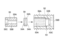
- FIG. 8 and FIG. 9 show a third embodiment of the present invention.
- the feature of this embodiment is that a ventilation member is installed in a communication hole of a plug body attached to a roller by using a retaining plug.
- the configuration is such that it is detachably held.
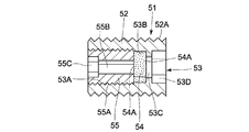
- reference numeral 51 denotes a vent plug used in the third embodiment.
- the vent plug 51 is provided on the lid 17 of the roller 15 shown in FIG. 2 in place of the vent plug 31 according to the first embodiment. It can be attached.
- the vent plug 51 includes a plug body 52, a vent member 54, and a retaining plug 55, which will be described later.
- a plug main body 52 forms an outer shell of the vent plug 51.
- the plug main body 52 is formed in a hollow cylindrical shape as a whole, and is screwed into the female screw hole 17D of the lid body 17 on the outer peripheral side of the plug main body 52.
- the male screw portion 52A is screwed.
- a communication hole 53 described later is formed on the inner peripheral side of the plug body 42.
- the communication hole 53 is a communication hole provided on the inner peripheral side of the plug main body 52, and the communication hole 53 is provided so as to penetrate the plug main body 52 in the axial direction.
- the communication hole 53 has a female screw portion 53A, a vent member accommodating portion 53B having a slightly smaller hole diameter than the female screw portion 53A, and a hole diameter smaller than that of the vent member accommodating portion 53B.
- An annular stopper portion 53C that opens to the ventilation member accommodating portion 53B and a hexagonal hole portion 53D having a larger hole diameter than the annular stopper portion 53C are configured.
- Reference numeral 54 denotes a ventilation member disposed in the communication hole 53 of the plug body 52.
- the ventilation member 54 is an open-cell porous material composed of a large number of small holes 54A, such as ethylene tetrafluoride resin (PTFE). Is formed in a disk shape having an outer diameter substantially equal to the hole diameter of the ventilation member accommodating portion 53B.
- the ventilation member 54 has a large number of small holes 54A provided therein to allow only a gas such as air or water vapor to circulate and prevent a liquid such as lubricating oil or rainwater or a solid such as dust from flowing. is there.
- Reference numeral 55 denotes a retaining plug that is screwed onto the female screw portion 53A of the communication hole 53.
- the retaining plug 55 sandwiches the ventilation member 54 with the annular stopper portion 53C of the communication hole 53.
- the ventilation member 54 is prevented from being removed from the communication hole 53 in the axial direction.
- the retaining plug 55 is formed in a hollow cylindrical shape as a whole, and a male thread portion 55 ⁇ / b> A that engages with the female thread portion 53 ⁇ / b> A of the communication hole 53 is screwed on the outer peripheral side of the retaining plug 55.
- vent hole 55B penetrating the retaining plug 55 in the axial direction and a larger diameter than the vent hole 55B.
- hexagonal hole 55C that engages (not shown).
- the ventilation member 54 when the ventilation member 54 is disposed in the communication hole 53 of the plug main body 52, the ventilation member 54 is retained in the communication hole 53 while the ventilation member 54 is accommodated in the ventilation member accommodation portion 53 ⁇ / b> B of the communication hole 53.
- the male screw portion 55A of the plug 55 is screwed and tightened using a hexagon wrench (not shown) engaged with the hexagon hole 55C of the retaining plug 55. Accordingly, the retaining plug 55 is fixed in the communication hole 53 of the plug body 52, and the ventilation member 54 is inserted into the communication hole 53 of the plug body 52 by the annular stopper portion 53 ⁇ / b> C of the communication hole 53 and the retaining plug 55. It can be held in a retaining state.
- the vent plug 51 in which the vent member 54 is disposed is formed in the communication hole 53 of the plug main body 52, and the vent plug 51 is a female screw hole provided in the lid body 17 of the roller 15 shown in FIG.
- the male screw portion 52A is screwed into 17D.
- the vent plug 51 is detachably attached to the lid body 17 and is fastened to the lid body 17 using a hexagon wrench (not shown) engaged with the hexagonal hole portion 53D of the communication hole 53. It has become.
- the upper crawler belt guide roller according to the third embodiment uses the vent plug 51 as described above, and the vent plug 51 used in the present embodiment removes the retaining plug 55 from the communication hole 53 of the plug body 52.
- the ventilation member 54 in the communication hole 53 can be exchanged.
- air and water vapor can be reliably circulated between the inside and outside of the roller 15 through the vent plug 51, and the pressure inside the roller 15 and the outside pressure can be equalized over a long period of time.
- the sealing performance of the floating seal 23 can be kept good over a long period of time.
- the upper crawler belt guide roller 11 is taken as an example of the rotation device of the construction machine, and the case where the vent plug 31 is attached to the roller 15 of the upper crawler belt guide roller 11 is illustrated.
- the construction machine rotating device according to the present invention may be applied to the lower crawler belt guide roller 10 as in the first modification shown in FIG.
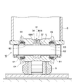
- the lower crawler belt guide roller 10 includes a left and right shaft support member 61 as a fixed body fixed to the lower end side of the side frame 6, and a roller support shaft 62 fixed between the shaft support members 61.
- a roller 64 as a rotating body rotatably supported by the roller support shaft 62 via a bearing 63, and left and right floating members provided between the left and right shaft support members 61 and the roller 64, respectively.
- the seal 65 is generally constituted.
- An oil reservoir chamber 64 ⁇ / b> A for storing the lubricating oil L supplied to the sliding surface between the roller 64 and the bearing 63 is provided in an intermediate portion in the axial direction of the roller 64, and this lubricating oil L is transferred to the roller by the floating seal 65. It is configured to be sealed in 64 oil sump chambers 64A.
- a female screw hole 64B that communicates the oil reservoir chamber 64A of the roller 64 with the outside is screwed in the axially intermediate portion of the roller 64, and the vent plug 31 is attached to the female screw hole 64B, whereby the roller 64
- the internal pressure and the external pressure can be equalized, and the sealing performance of the floating seal 65 can be maintained well over a long period of time.
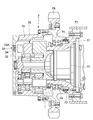
- the rotating device for a construction machine according to the present invention may be applied to the traveling device 7 as in the second modification shown in FIG. 11, for example.
- the traveling device 7 includes a motor housing 72 as a fixed body fixed to the drive wheel bracket 71, a hydraulic motor 73 disposed in the motor housing 72 and attached to the drive wheel bracket 71, and a motor housing 72.
- a reduction gear housing 75 as a rotating body that is rotatably attached to the outer peripheral side via a bearing 74 and to which the drive wheel 7A is fixed, and provided in the reduction gear housing 75, reduces the rotation of the hydraulic motor 73.
- a planetary gear speed reduction mechanism 76 that transmits to the reduction gear housing 75 and a floating seal 77 provided between the motor housing 72 and the reduction gear housing 75 are roughly configured.
- Lubricating oil L that lubricates the bearings 74, the planetary gear speed reducing mechanism 76, and the like is stored on the inner peripheral side of the motor housing 72 and the speed reducer housing 75. It becomes the structure which stops.
- a female screw hole 75A communicating the inside and the outside of the reduction gear housing 75 is screwed on the axial end surface of the reduction gear housing 75, and the vent plug 31 is attached to the female screw hole 75A, thereby reducing the reduction gear.
- the internal pressure of the housing 75 and the external pressure can be equalized, and the sealing performance of the floating seal 77 can be maintained satisfactorily over a long period.
- the communication hole 33 is sandwiched between the one end side caulking portion 33C and the other end side caulking portion 33D provided in the communication hole 33 of the vent plug 31.
- the case where the ventilation member 34 is fixed inside is illustrated.
- the present invention is not limited to this.
- the ventilation member 34 is placed in the communication hole 33. It is good also as composition which adheres to.
Landscapes
- Engineering & Computer Science (AREA)
- Mechanical Engineering (AREA)
- Chemical & Material Sciences (AREA)
- Combustion & Propulsion (AREA)
- Transportation (AREA)
- General Engineering & Computer Science (AREA)
- Mechanical Sealing (AREA)
- General Details Of Gearings (AREA)
- Sealing Using Fluids, Sealing Without Contact, And Removal Of Oil (AREA)
Abstract
Description


2 下部走行体(車体)
7 走行装置(回転装置)
10 下履帯案内ローラ(回転装置)
11 上履帯案内ローラ(回転装置)
12 取付ブラケット(固定体)
15,64 ローラ(回転体)
23,65,77 フローティングシール
31,41,51 通気栓
32,42,52 栓本体
33,43,53 連通孔
34,44,54 通気部材
34A,44A,54A 小孔
61 軸支持部材(固定体)
72 モータハウジング(固定体)
75 減速機ハウジング(回転体)
Claims (6)
- 建設機械の車体に固定して設けられた固定体と、該固定体に対して回転可能に設けられ内部に潤滑油が貯溜される回転体と、前記固定体と前記回転体との間の隙間を閉塞し、前記回転体の内部に貯溜された潤滑油を封止すると共に外部からの雨水、塵埃の侵入を阻止するフローティングシールとを備えてなる建設機械の回転装置において、
前記回転体には、前記回転体の内部と外部との間で空気および/または水蒸気を流通させると共に潤滑油および/または雨水、塵埃の流通を阻止する通気栓を設けたことを特徴とする建設機械の回転装置。 - 前記通気栓は、前記回転体に着脱可能に取付けられ前記回転体の内部と外部との間を連通させる連通孔が設けられた栓本体と、該栓本体の連通孔内に配設され空気および/または水蒸気の流通を許すと共に潤滑油および/または雨水、塵埃の流通を阻止する通気部材とにより構成してなる請求項1に記載の建設機械の回転装置。
- 前記通気部材は、連続気泡の多孔質材料を用いて形成してなる請求項2に記載の建設機械の回転装置。
- 前記通気部材は、四ふっ化エチレン樹脂、ポリイミド樹脂、セラミック材のうちいずれか一の材料からなる連続気泡の多孔質材料を用いて形成してなる請求項2に記載の建設機械の回転装置。
- 前記通気部材を構成する各小孔の孔径は、0.1μm以上でかつ10μm以下の範囲に設定してなる請求項2,3または4に記載の建設機械の回転装置。
- 前記通気部材を構成する各小孔の孔径は、0.15μm以上でかつ0.3μm以下の範囲に設定してなる請求項2,3または4に記載の建設機械の回転装置。
Priority Applications (6)
| Application Number | Priority Date | Filing Date | Title |
|---|---|---|---|
| US13/979,198 US9260143B2 (en) | 2011-04-28 | 2011-04-28 | Rotation device for construction machine |
| KR1020137024009A KR101781097B1 (ko) | 2011-04-28 | 2011-04-28 | 건설 기계의 회전 장치 |
| CN201180069582.3A CN103459241B (zh) | 2011-04-28 | 2011-04-28 | 工程机械的旋转装置 |
| PCT/JP2011/060440 WO2012147201A1 (ja) | 2011-04-28 | 2011-04-28 | 建設機械の回転装置 |
| DE112011105188.3T DE112011105188T5 (de) | 2011-04-28 | 2011-04-28 | Drehvorrichtung für Baumaschine |
| JP2013511854A JP5596224B2 (ja) | 2011-04-28 | 2011-04-28 | 建設機械の回転装置 |
Applications Claiming Priority (1)
| Application Number | Priority Date | Filing Date | Title |
|---|---|---|---|
| PCT/JP2011/060440 WO2012147201A1 (ja) | 2011-04-28 | 2011-04-28 | 建設機械の回転装置 |
Publications (1)
| Publication Number | Publication Date |
|---|---|
| WO2012147201A1 true WO2012147201A1 (ja) | 2012-11-01 |
Family
ID=47071741
Family Applications (1)
| Application Number | Title | Priority Date | Filing Date |
|---|---|---|---|
| PCT/JP2011/060440 Ceased WO2012147201A1 (ja) | 2011-04-28 | 2011-04-28 | 建設機械の回転装置 |
Country Status (6)
| Country | Link |
|---|---|
| US (1) | US9260143B2 (ja) |
| JP (1) | JP5596224B2 (ja) |
| KR (1) | KR101781097B1 (ja) |
| CN (1) | CN103459241B (ja) |
| DE (1) | DE112011105188T5 (ja) |
| WO (1) | WO2012147201A1 (ja) |
Cited By (1)
| Publication number | Priority date | Publication date | Assignee | Title |
|---|---|---|---|---|
| CN107745754A (zh) * | 2017-11-09 | 2018-03-02 | 徐工集团工程机械有限公司 | 高可靠性导向轮结构及挖掘机 |
Families Citing this family (5)
| Publication number | Priority date | Publication date | Assignee | Title |
|---|---|---|---|---|
| US9440692B2 (en) * | 2012-07-30 | 2016-09-13 | Cnh Industrial America Llc | Pin assembly for a tracked work vehicle suspension system |
| US9755484B2 (en) * | 2014-12-15 | 2017-09-05 | Hamilton Sundstrand Corporation | Methods and systems of air bubble flushing in liquid cooled generators |
| US10046817B2 (en) | 2016-10-10 | 2018-08-14 | Caterpillar Inc. | Scallop resistant idler heat treatment |
| JP6732692B2 (ja) * | 2017-03-31 | 2020-07-29 | 住友建機株式会社 | ショベル |
| KR20200141159A (ko) | 2019-06-10 | 2020-12-18 | 현대코어모션 주식회사 | 이물질 배출 패드를 구비한 주행감속기 |
Citations (6)
| Publication number | Priority date | Publication date | Assignee | Title |
|---|---|---|---|---|
| JPS57205280A (en) * | 1981-06-13 | 1982-12-16 | Hitachi Constr Mach Co Ltd | Upper shaft sleeve device for crawler vehicle |
| JPH04353084A (ja) * | 1991-05-29 | 1992-12-08 | Kubota Corp | クローラ走行装置の転輪構造 |
| JP3010441U (ja) * | 1994-10-20 | 1995-05-02 | 古河機械金属株式会社 | シールの構造 |
| JPH08324323A (ja) * | 1995-03-29 | 1996-12-10 | Shin Caterpillar Mitsubishi Ltd | 上部旋回体を備えた運搬車両 |
| JP2004082819A (ja) * | 2002-08-26 | 2004-03-18 | Komatsu Ltd | 履帯式走行装置の転輪 |
| JP2006322538A (ja) * | 2005-05-19 | 2006-11-30 | Uchiyama Mfg Corp | シールリング及びその製造方法 |
Family Cites Families (6)
| Publication number | Priority date | Publication date | Assignee | Title |
|---|---|---|---|---|
| JPS61169602U (ja) * | 1985-04-08 | 1986-10-21 | ||
| US6074023A (en) * | 1996-07-24 | 2000-06-13 | Hitachi Construction Machinery Co., Ltd. | Guide roller assembly for crawler type vehicles and method for forming guide roller |
| JP2001080550A (ja) | 1999-09-09 | 2001-03-27 | Hitachi Constr Mach Co Ltd | 装軌式車両の案内ローラ装置 |
| JP2004011771A (ja) * | 2002-06-06 | 2004-01-15 | Koyo Seiko Co Ltd | トルク伝達装置 |
| CN201195562Y (zh) * | 2008-04-10 | 2009-02-18 | 中国一拖集团有限公司 | 一种挖掘机支重轮 |
| US8485289B2 (en) * | 2011-02-24 | 2013-07-16 | Deere & Company | Air pressure regulated axle sump |
-
2011
- 2011-04-28 CN CN201180069582.3A patent/CN103459241B/zh active Active
- 2011-04-28 JP JP2013511854A patent/JP5596224B2/ja not_active Expired - Fee Related
- 2011-04-28 US US13/979,198 patent/US9260143B2/en not_active Expired - Fee Related
- 2011-04-28 KR KR1020137024009A patent/KR101781097B1/ko active Active
- 2011-04-28 WO PCT/JP2011/060440 patent/WO2012147201A1/ja not_active Ceased
- 2011-04-28 DE DE112011105188.3T patent/DE112011105188T5/de not_active Ceased
Patent Citations (6)
| Publication number | Priority date | Publication date | Assignee | Title |
|---|---|---|---|---|
| JPS57205280A (en) * | 1981-06-13 | 1982-12-16 | Hitachi Constr Mach Co Ltd | Upper shaft sleeve device for crawler vehicle |
| JPH04353084A (ja) * | 1991-05-29 | 1992-12-08 | Kubota Corp | クローラ走行装置の転輪構造 |
| JP3010441U (ja) * | 1994-10-20 | 1995-05-02 | 古河機械金属株式会社 | シールの構造 |
| JPH08324323A (ja) * | 1995-03-29 | 1996-12-10 | Shin Caterpillar Mitsubishi Ltd | 上部旋回体を備えた運搬車両 |
| JP2004082819A (ja) * | 2002-08-26 | 2004-03-18 | Komatsu Ltd | 履帯式走行装置の転輪 |
| JP2006322538A (ja) * | 2005-05-19 | 2006-11-30 | Uchiyama Mfg Corp | シールリング及びその製造方法 |
Cited By (1)
| Publication number | Priority date | Publication date | Assignee | Title |
|---|---|---|---|---|
| CN107745754A (zh) * | 2017-11-09 | 2018-03-02 | 徐工集团工程机械有限公司 | 高可靠性导向轮结构及挖掘机 |
Also Published As
| Publication number | Publication date |
|---|---|
| JP5596224B2 (ja) | 2014-09-24 |
| US9260143B2 (en) | 2016-02-16 |
| KR101781097B1 (ko) | 2017-09-22 |
| CN103459241A (zh) | 2013-12-18 |
| DE112011105188T5 (de) | 2014-01-23 |
| US20130285439A1 (en) | 2013-10-31 |
| CN103459241B (zh) | 2016-01-06 |
| JPWO2012147201A1 (ja) | 2014-07-28 |
| KR20140006947A (ko) | 2014-01-16 |
Similar Documents
| Publication | Publication Date | Title |
|---|---|---|
| JP5596224B2 (ja) | 建設機械の回転装置 | |
| RU2570853C1 (ru) | Шпиндельный узел для системы накачивания шины | |
| JP5128720B2 (ja) | 転輪装置 | |
| JP4616879B2 (ja) | 軸受装置 | |
| CN104203732B (zh) | 履带式作业车辆用的辊装置 | |
| US3073657A (en) | Rotary seal | |
| WO2015041337A1 (ja) | 転がり軸受の密封装置 | |
| US20210285550A1 (en) | Traveling Device for Construction Machine | |
| CN102574464B (zh) | 用于接合驱动组件的轴承的推力板 | |
| JP2010052596A (ja) | 建設機械の回転装置 | |
| CN106541824A (zh) | 行驶用车轴装置 | |
| WO2020217993A1 (ja) | 履帯式走行装置の転輪、履帯式走行装置および作業機械 | |
| JP2012071647A (ja) | 建設機械の回転装置 | |
| JP2009068506A (ja) | 減速装置 | |
| US20150192207A1 (en) | Shaft seal assembly for final drive system | |
| JP2012207489A (ja) | 建設機械の回転装置 | |
| JP4728057B2 (ja) | ダンプトラックの走行駆動装置 | |
| JP4131504B2 (ja) | 履帯式走行装置における下転輪ボギーのピン組立体と同組立体を備えた履帯式走行装置 | |
| JP7709936B2 (ja) | 建設機械の転輪装置 | |
| JP2017065294A (ja) | 建設機械の回転装置 | |
| JP3981229B2 (ja) | 車両の左右駆動力配分装置 | |
| JP2007283835A (ja) | 建設機械に用いる回転装置 | |
| JPH107039A (ja) | 履帯式走行車両のトラックローラ組立体 | |
| JPH0754696Y2 (ja) | シール装置 | |
| JPH08282554A (ja) | 転動体装置 |
Legal Events
| Date | Code | Title | Description |
|---|---|---|---|
| 121 | Ep: the epo has been informed by wipo that ep was designated in this application |
Ref document number: 11864570 Country of ref document: EP Kind code of ref document: A1 |
|
| ENP | Entry into the national phase |
Ref document number: 2013511854 Country of ref document: JP Kind code of ref document: A |
|
| WWE | Wipo information: entry into national phase |
Ref document number: 13979198 Country of ref document: US |
|
| ENP | Entry into the national phase |
Ref document number: 20137024009 Country of ref document: KR Kind code of ref document: A |
|
| WWE | Wipo information: entry into national phase |
Ref document number: 1120111051883 Country of ref document: DE Ref document number: 112011105188 Country of ref document: DE |
|
| 122 | Ep: pct application non-entry in european phase |
Ref document number: 11864570 Country of ref document: EP Kind code of ref document: A1 |