WO2012147137A1 - Bloc-batterie - Google Patents
Bloc-batterie Download PDFInfo
- Publication number
- WO2012147137A1 WO2012147137A1 PCT/JP2011/002510 JP2011002510W WO2012147137A1 WO 2012147137 A1 WO2012147137 A1 WO 2012147137A1 JP 2011002510 W JP2011002510 W JP 2011002510W WO 2012147137 A1 WO2012147137 A1 WO 2012147137A1
- Authority
- WO
- WIPO (PCT)
- Prior art keywords
- battery
- heater
- power
- holder
- battery pack
- Prior art date
Links
Images


Classifications
-
- B—PERFORMING OPERATIONS; TRANSPORTING
- B60—VEHICLES IN GENERAL
- B60L—PROPULSION OF ELECTRICALLY-PROPELLED VEHICLES; SUPPLYING ELECTRIC POWER FOR AUXILIARY EQUIPMENT OF ELECTRICALLY-PROPELLED VEHICLES; ELECTRODYNAMIC BRAKE SYSTEMS FOR VEHICLES IN GENERAL; MAGNETIC SUSPENSION OR LEVITATION FOR VEHICLES; MONITORING OPERATING VARIABLES OF ELECTRICALLY-PROPELLED VEHICLES; ELECTRIC SAFETY DEVICES FOR ELECTRICALLY-PROPELLED VEHICLES
- B60L1/00—Supplying electric power to auxiliary equipment of vehicles
- B60L1/02—Supplying electric power to auxiliary equipment of vehicles to electric heating circuits
- B60L1/04—Supplying electric power to auxiliary equipment of vehicles to electric heating circuits fed by the power supply line
- B60L1/06—Supplying electric power to auxiliary equipment of vehicles to electric heating circuits fed by the power supply line using only one supply
-
- B—PERFORMING OPERATIONS; TRANSPORTING
- B60—VEHICLES IN GENERAL
- B60L—PROPULSION OF ELECTRICALLY-PROPELLED VEHICLES; SUPPLYING ELECTRIC POWER FOR AUXILIARY EQUIPMENT OF ELECTRICALLY-PROPELLED VEHICLES; ELECTRODYNAMIC BRAKE SYSTEMS FOR VEHICLES IN GENERAL; MAGNETIC SUSPENSION OR LEVITATION FOR VEHICLES; MONITORING OPERATING VARIABLES OF ELECTRICALLY-PROPELLED VEHICLES; ELECTRIC SAFETY DEVICES FOR ELECTRICALLY-PROPELLED VEHICLES
- B60L50/00—Electric propulsion with power supplied within the vehicle
- B60L50/50—Electric propulsion with power supplied within the vehicle using propulsion power supplied by batteries or fuel cells
- B60L50/60—Electric propulsion with power supplied within the vehicle using propulsion power supplied by batteries or fuel cells using power supplied by batteries
- B60L50/64—Constructional details of batteries specially adapted for electric vehicles
-
- B—PERFORMING OPERATIONS; TRANSPORTING
- B60—VEHICLES IN GENERAL
- B60L—PROPULSION OF ELECTRICALLY-PROPELLED VEHICLES; SUPPLYING ELECTRIC POWER FOR AUXILIARY EQUIPMENT OF ELECTRICALLY-PROPELLED VEHICLES; ELECTRODYNAMIC BRAKE SYSTEMS FOR VEHICLES IN GENERAL; MAGNETIC SUSPENSION OR LEVITATION FOR VEHICLES; MONITORING OPERATING VARIABLES OF ELECTRICALLY-PROPELLED VEHICLES; ELECTRIC SAFETY DEVICES FOR ELECTRICALLY-PROPELLED VEHICLES
- B60L58/00—Methods or circuit arrangements for monitoring or controlling batteries or fuel cells, specially adapted for electric vehicles
- B60L58/10—Methods or circuit arrangements for monitoring or controlling batteries or fuel cells, specially adapted for electric vehicles for monitoring or controlling batteries
- B60L58/18—Methods or circuit arrangements for monitoring or controlling batteries or fuel cells, specially adapted for electric vehicles for monitoring or controlling batteries of two or more battery modules
- B60L58/20—Methods or circuit arrangements for monitoring or controlling batteries or fuel cells, specially adapted for electric vehicles for monitoring or controlling batteries of two or more battery modules having different nominal voltages
-
- B—PERFORMING OPERATIONS; TRANSPORTING
- B60—VEHICLES IN GENERAL
- B60L—PROPULSION OF ELECTRICALLY-PROPELLED VEHICLES; SUPPLYING ELECTRIC POWER FOR AUXILIARY EQUIPMENT OF ELECTRICALLY-PROPELLED VEHICLES; ELECTRODYNAMIC BRAKE SYSTEMS FOR VEHICLES IN GENERAL; MAGNETIC SUSPENSION OR LEVITATION FOR VEHICLES; MONITORING OPERATING VARIABLES OF ELECTRICALLY-PROPELLED VEHICLES; ELECTRIC SAFETY DEVICES FOR ELECTRICALLY-PROPELLED VEHICLES
- B60L58/00—Methods or circuit arrangements for monitoring or controlling batteries or fuel cells, specially adapted for electric vehicles
- B60L58/10—Methods or circuit arrangements for monitoring or controlling batteries or fuel cells, specially adapted for electric vehicles for monitoring or controlling batteries
- B60L58/24—Methods or circuit arrangements for monitoring or controlling batteries or fuel cells, specially adapted for electric vehicles for monitoring or controlling batteries for controlling the temperature of batteries
- B60L58/27—Methods or circuit arrangements for monitoring or controlling batteries or fuel cells, specially adapted for electric vehicles for monitoring or controlling batteries for controlling the temperature of batteries by heating
-
- B—PERFORMING OPERATIONS; TRANSPORTING
- B60—VEHICLES IN GENERAL
- B60L—PROPULSION OF ELECTRICALLY-PROPELLED VEHICLES; SUPPLYING ELECTRIC POWER FOR AUXILIARY EQUIPMENT OF ELECTRICALLY-PROPELLED VEHICLES; ELECTRODYNAMIC BRAKE SYSTEMS FOR VEHICLES IN GENERAL; MAGNETIC SUSPENSION OR LEVITATION FOR VEHICLES; MONITORING OPERATING VARIABLES OF ELECTRICALLY-PROPELLED VEHICLES; ELECTRIC SAFETY DEVICES FOR ELECTRICALLY-PROPELLED VEHICLES
- B60L2240/00—Control parameters of input or output; Target parameters
- B60L2240/40—Drive Train control parameters
- B60L2240/54—Drive Train control parameters related to batteries
- B60L2240/545—Temperature
-
- H—ELECTRICITY
- H02—GENERATION; CONVERSION OR DISTRIBUTION OF ELECTRIC POWER
- H02J—CIRCUIT ARRANGEMENTS OR SYSTEMS FOR SUPPLYING OR DISTRIBUTING ELECTRIC POWER; SYSTEMS FOR STORING ELECTRIC ENERGY
- H02J7/00—Circuit arrangements for charging or depolarising batteries or for supplying loads from batteries
- H02J7/007—Regulation of charging or discharging current or voltage
- H02J7/007188—Regulation of charging or discharging current or voltage the charge cycle being controlled or terminated in response to non-electric parameters
- H02J7/007192—Regulation of charging or discharging current or voltage the charge cycle being controlled or terminated in response to non-electric parameters in response to temperature
-
- Y—GENERAL TAGGING OF NEW TECHNOLOGICAL DEVELOPMENTS; GENERAL TAGGING OF CROSS-SECTIONAL TECHNOLOGIES SPANNING OVER SEVERAL SECTIONS OF THE IPC; TECHNICAL SUBJECTS COVERED BY FORMER USPC CROSS-REFERENCE ART COLLECTIONS [XRACs] AND DIGESTS
- Y02—TECHNOLOGIES OR APPLICATIONS FOR MITIGATION OR ADAPTATION AGAINST CLIMATE CHANGE
- Y02T—CLIMATE CHANGE MITIGATION TECHNOLOGIES RELATED TO TRANSPORTATION
- Y02T10/00—Road transport of goods or passengers
- Y02T10/60—Other road transportation technologies with climate change mitigation effect
- Y02T10/70—Energy storage systems for electromobility, e.g. batteries
Definitions
- the present invention relates to a battery pack in which a high-power battery and a high-capacity battery are electrically connected in parallel.
- the output may decrease. Therefore, there is a technique for warming the secondary battery in order to suppress a decrease in the output of the secondary battery.
- the entire assembled battery is heated.
- the heater becomes larger or the power consumption of the heater increases as the heater becomes larger.
- the battery pack according to the present invention includes a first battery and a second battery that are electrically connected in parallel and charge and discharge, and a heater that generates heat.
- the first battery can be charged / discharged with a larger current than the second battery.
- the second battery has a larger storage capacity than the first battery.
- the heater is disposed closer to the first battery than the second battery.
- the first battery and the second battery can be held using the holder.
- the heater can be fixed to the holder.
- the first battery and the second battery can be held by forming a plurality of openings penetrating the holder in the holder and inserting the first battery and the second battery into the opening.
- the holder can be formed of metal, for example. If the holder is made of metal, heat generated in the first battery or the second battery by charge / discharge can be easily transmitted to the holder, and the temperature rise of the first battery or the second battery can be suppressed.
- the holder can be provided with a first holding part for holding the first battery and a second holding part for holding the second battery.
- a region having a lower thermal conductivity than the first holding unit referred to as a heat transfer suppression region
- the first holding unit and the second holding unit can be made of metal
- the heat transfer suppression region can be made of resin.
- a plurality of first and second batteries can be used.
- the plurality of first batteries and the plurality of second batteries are electrically connected in parallel.
- the heater can be arranged along the arrangement direction of the plurality of first batteries.
- Cylindrical batteries can be used as the first battery and the second battery.
- the heater since the heater is disposed with respect to the first battery, the heater can be reduced in size as compared with the case where the heater is disposed with respect to both the first battery and the second battery. . And if a heater is reduced in size, the power consumption of a heater can be reduced.
- the first battery can be charged / discharged with a larger current than the second battery, even if the output of the second battery decreases due to the temperature decrease of the battery pack, the output of the first battery is used.
- the output of the battery pack can be suppressed from decreasing.
- the output of the battery pack can be recovered simply by warming the first battery.
- Example 1 is a diagram illustrating an internal structure of a battery pack that is Embodiment 1.
- Example 1 it is a figure which shows the arrangement
- Example 1 it is a front view of a holder.
- Example 1 it is a figure which shows the structure by which the some battery pack was electrically connected in series.
- Example 1 it is a figure explaining arrangement
- Example 1 it is the schematic which shows the circuit structure which drives a heater.
- the holder of Example 1 it is a figure explaining the position of the heat-transfer suppression area
- FIG. 1 is a diagram showing the internal structure of the battery pack according to this embodiment.
- the battery pack 1 includes a plurality of unit cells 10 and a case 20 that houses the plurality of unit cells 10.
- the case 20 has a case main body 21 and a lid 22.
- the lid 22 is fixed to the upper end of the case body 21 and closes the opening 21 a formed in the case body 21.
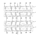
- the plurality of single cells 10 accommodated in the case 20 are arranged as shown in FIG. 1 and 2, the X axis, the Y axis, and the Z axis are axes orthogonal to each other.
- the plurality of unit cells 10 are arranged side by side in the YZ plane. Note that the plurality of single cells 10 may be arranged in an arrangement different from the arrangement shown in FIG. Further, the number of unit cells 10 can be appropriately selected in consideration of input / output characteristics of the battery pack 1.
- the single battery 10 is a so-called cylindrical battery. That is, the unit cell 10 extends in the X direction, and the cross-sectional shape of the unit cell 10 in the YZ plane is circular.
- a secondary battery such as a nickel metal hydride battery or a lithium ion battery can be used.
- the unit cell 10 includes a battery case 11 and a power generation element accommodated in the battery case 11.
- the power generation element is an element that performs charge and discharge, and includes a positive electrode plate, a negative electrode plate, and a separator disposed between the positive electrode plate and the negative electrode plate.
- the separator contains an electrolytic solution.
- a positive electrode terminal 12 and a negative electrode terminal 13 are provided at both ends of the unit cell 10 in the X direction.
- the positive electrode plate of the power generation element is electrically connected to the positive electrode terminal 12.
- the positive terminal 12 has a convex surface.
- the negative electrode plate of the power generation element is electrically connected to the negative electrode terminal 13.
- the negative electrode terminal 13 is configured by a flat surface.
- the positive electrode terminal 12 and the negative electrode terminal 13 constitute a battery case 11.
- a plurality of single cells 10 are held by a holder 30.
- the holder 30 is omitted.
- the holder 30 holds the central portion of each unit cell 10 in the X direction.
- the holder 30 has as many holding portions 31 as the number of the unit cells 10.
- the holding part 31 is configured as an opening that penetrates the holder 30.
- the plurality of single cells 10 are arranged side by side in the YZ plane. Specifically, a row of five unit cells 10 arranged in the Z direction and a row of four unit cells 10 arranged in the Z direction are alternately arranged in the Y direction.
- the holder 30 holds the central portion of the unit cell 10, but can also hold other portions.
- a plurality of unit cells 10 can be held using a plurality of holders 30.
- the plurality of holders 30 hold different portions of each unit cell 10.
- the unit cell 10 is inserted into the holding unit 31, and a gap formed between the holding unit 31 and the unit cell 10 is filled with an adhesive.
- an adhesive can be used as the adhesive.
- the unit cell 10 can be fixed to the holder 30 by filling the gap formed between the holding unit 31 and the unit cell 10 with an adhesive.
- the holder 30 can be formed of a metal such as aluminum, for example. By forming the holder 30 with a metal, the heat dissipation of the unit cell 10 can be improved.
- the unit cell 10 may generate heat due to charging / discharging or the like. If the holder 30 is made of metal, the heat generated in the unit cell 10 can be easily released to the holder 30, and the temperature increase of the unit cell 10 can be suppressed.
- the holder 30 is fixed to the case 20.
- a known structure can be used as appropriate.
- the holder 30 can be fixed to the case 20 using a bolt.
- the positive terminals 12 in the plurality of single cells 10 are located on the same side with respect to the holder 30 and are connected to the connection member 41.
- the connection member 41 is made of a conductive material such as metal.
- the connection member 41 has a contact portion 41a that comes into contact with the positive electrode terminal 12, and the contact portions 41a are provided as many as the number of the unit cells 10 (positive electrode terminals 12).
- the contact part 41a and the positive electrode terminal 12 can be welded.
- the connecting member 41 has a lead part 41 b, and the lead part 41 b passes through the opening 22 a formed in the lid 22 and protrudes outside the case 20.
- the positive terminal 51 of the battery pack 1 is fixed to the lead portion 41b.
- the negative terminals 13 of the plurality of single cells 10 are located on the same side with respect to the holder 30 and are connected to the connection member 42.
- the connection member 42 is made of a conductive material such as metal.
- the connection member 42 has a structure similar to that of the connection member 41, and has a contact portion 42 a that contacts the negative electrode terminal 13.
- the contact part 42a is provided by the number of the unit cells 10 (negative electrode terminal 13), and can be welded to the negative electrode terminal 13.
- the connecting member 42 has a lead part 42 b, and the lead part 42 b passes through the opening 22 b formed in the lid 22 and protrudes outside the case 20.
- the negative terminal 52 of the battery pack 1 is fixed to the lead part 42b.
- connection members 41 and 42 have the same structure, but the present invention is not limited to this. Since the connection member 42 is connected to the negative electrode terminal 13 configured with a flat surface, for example, the connection member 42 formed in a flat plate shape can be used.
- the battery pack 1 can be used as a power source for running the vehicle. Specifically, as shown in FIG. 4, a plurality of battery packs 1 electrically connected in series can be mounted on the vehicle. The number of battery packs 1 mounted on the vehicle can be appropriately set in consideration of the required output of the vehicle.
- a plurality of battery packs 1 electrically connected in series can be connected to a motor / generator.
- the motor / generator receives the electric power output from the battery pack 1 and generates kinetic energy for running the vehicle.
- the motor / generator converts kinetic energy generated during braking of the vehicle into electric energy and supplies the electric energy to the battery pack 1.
- the battery pack 1 can store electric power (regenerative electric power) from the motor / generator.
- An inverter or a booster circuit can be arranged between the battery pack 1 and the motor / generator. If an inverter is used, an AC motor can be used as the motor / generator. If the booster circuit is used, the output voltage of the battery pack 1 can be boosted, or the output voltage of the motor / generator can be lowered.
- each battery pack 1 since the plurality of unit cells 10 are electrically connected in parallel, the capacity of the battery pack 1 is increased as compared with the case where the plurality of unit cells 10 are electrically connected in series. Can do. Therefore, the travel distance of the vehicle using the output of the battery pack 1 can be extended.
- the battery pack 1 includes a high-power battery (corresponding to the first battery) 10 ⁇ / b> A and a high-capacity battery (corresponding to the second battery) 10 ⁇ / b> B as the unit cells 10.
- the high-power battery 10A is a battery that can be charged and discharged with a larger current than the high-capacity battery 10B.
- the high capacity battery 10B is a battery having a larger storage capacity than the high power battery 10A.
- the high-power battery 10A and the high-capacity battery 10B have the relationship shown in Table 1 below when compared with each other.
- the output of the cell 10 (10A, 10B) is, for example, the power per unit mass of the cell 10 (unit [W / kg]) or the power per unit volume of the cell 10 (unit [W / L]).
- the high-power battery 10A is higher than the high-capacity battery 10B.
- the output [W] of the high-power battery 10A is higher than the output [W] of the high-capacity battery 10B.
- the capacity of the cell 10 (10A, 10B) is, for example, the capacity per unit mass of the cell 10 (unit [Wh / kg]) or the capacity per unit volume of the cell 10 (unit [Wh / L]).
- the high-capacity battery 10B is larger than the high-power battery 10A.
- the capacity [Wh] of the high-capacity battery 10B is larger than the capacity [Wh] of the high-power battery 10A.
- the output of the electrode of the unit cell 10 can be expressed, for example, as a current value per unit area of the electrode (unit [mA / cm ⁇ 2]).
- the high-power battery 10A is higher than the high-capacity battery 10B.
- the current value flowing through the electrode of the high-power battery 10A is larger than the current value flowing through the electrode of the high-capacity battery 10B.
- the capacity of the electrode of the unit cell 10 can be expressed as, for example, the capacity per unit mass of the electrode (unit [mAh / g]) or the capacity per unit volume of the electrode (unit [mAh / cc]).
- the high-capacity battery 10B is larger than the high-power battery 10A.
- the capacity of the electrode of the high capacity battery 10B is larger than the capacity of the electrode of the high power battery 10A.
- a lithium ion battery is used as the unit cells 10A and 10B
- hard carbon non-graphitizable carbon material
- Lithium / manganese complex oxides can be used as the negative electrode active material of the high capacity battery 10B
- lithium / nickel composite oxide can be used as the positive electrode active material of the high capacity battery 10B.
- the high-power battery 10A and the high-capacity battery 10B are arranged as shown in FIG.
- five high-power batteries 10A are used, and the five high-power batteries 10A are arranged in the Z direction.
- All the unit cells 10 other than the high-power battery 10A are high-capacity batteries 10B.
- the number of the high-power battery 10A and the high-capacity battery 10B can be appropriately set in consideration of the required characteristics of the battery pack 1. If the ratio of the number of high-power batteries 10A among the plurality of single cells 10 constituting the battery pack 1 is increased, the output of the battery pack 1 can be improved without changing the voltage of the battery pack 1. Further, if the ratio of the number of high-capacity batteries 10B is increased, the storage capacity of the battery pack 1 can be increased without changing the voltage of the battery pack 1.
- the heater 60 is disposed along the side surface 32 of the holder 30.
- the side surface 32 extends in the arrangement direction (Z direction) of the plurality of high-power batteries 10A. Therefore, the heater 60 is disposed along the plurality of high-power batteries 10A. By energizing the heater 60, the heater 60 can generate heat. Any heater 60 may be used as long as it generates heat when energized.
- the heater 60 is connected to a power source 71 and generates heat upon receiving power from the power source 71.
- a switch 72 is disposed between the heater 60 and the power source 71. If the switch 72 is on, the power of the power source 71 is supplied to the heater 60. If the switch 72 is in the off state, the power of the power source 71 is not supplied to the heater 60.
- the battery pack 1 can be used, or a power source different from the battery pack 1 can be used.
- Controller 73 switches on / off of switch 72 based on the output of temperature sensor 74. Specifically, the controller 73 turns off the switch 72 when the temperature obtained from the output of the temperature sensor 74 is higher than a threshold value. The controller 73 turns on the switch 72 when the temperature obtained from the output of the temperature sensor 74 is lower than the threshold.
- the threshold value can be determined in advance, and information about the threshold value can be stored in the memory. As described later, the threshold value can be determined based on the relationship between the temperature and output characteristics of the high-power battery 10A. That is, the temperature at which the output of the high-power battery 10A is likely to decrease can be determined as the threshold value.
- the temperature sensor 74 should just be arrange
- FIG. the temperature sensor 74 can be brought into contact with some high-power batteries 10A. Further, the temperature sensor 74 can be fixed to the case 20 of the battery pack 1 in a state where the temperature sensor 74 is separated from the unit cell 10. The number of temperature sensors 74 can be set as appropriate. When a plurality of temperature sensors 74 are used, the temperature sensors 74 can be arranged at different positions in the battery pack 1.
- the holder 30 has a heat transfer suppression region R1. As shown in FIG. 7, the heat transfer suppression region R1 is provided on the boundary line between the region R2 that holds the high-power battery 10A and the region R3 that holds the high-capacity battery 10B. In other words, the heat transfer suppression region R1 is located between the holding unit 31 that holds the high-power battery 10A and the holding unit 31 that holds the high-capacity battery 10B.
- the heat transfer suppression region R1 is provided to suppress the heat generated by the heater 60 from being transmitted from the region R2 to the region R3. Thereby, the heat generated by the heater 60 is transmitted to the entire region R2, and can be positively applied to the high-power battery 10A.
- the heat transfer suppression region R1 can be formed of a material having a lower thermal conductivity than the material forming the region R2.
- the regions R2 and R3 can be formed of metal and the region R1 can be formed of resin.
- region R3 are prepared, respectively,
- the holder 30 can be comprised by fixing these members. .
- the members constituting the regions R2 and R3 are formed with the holding portions 31 as described above.
- the heat transfer suppression region R1 is provided at the position shown in FIG. 5 and FIG. 7, but the present invention is not limited to this.
- the position where the heat transfer suppression region R1 is provided varies depending on the positions of the high-power battery 10A and the high-capacity battery 10B. As described above, the heat transfer suppression region R1 only needs to be located between the region R2 that holds the high-power battery 10A and the region R3 that holds the high-capacity battery 10B.
- the output of the single cell 10 tends to decrease as the temperature decreases.
- the high-power battery 10A is included in the plurality of single cells 10, it is possible to suppress the output of the battery pack 1 from being reduced due to a decrease in temperature. That is, even if the output of the high-capacity battery 10B decreases due to a decrease in temperature, the output of the battery pack 1 can be prevented from decreasing due to the output of the high-power battery 10A.
- the output of the battery pack 1 can be suppressed from decreasing by driving the heater 60 to warm the high-power battery 10A.
- the heater 60 is disposed only for the high-power battery 10A, the heater is compared to the case where the heater 60 is disposed for both the high-power battery 10A and the high-capacity battery 10B. 60 can be reduced in size. As the heater 60 is downsized, the power consumption of the heater 60 can be reduced. Further, in this embodiment, since only the high-power battery 10A is actively warmed, the time for warming the unit cell 10 is shortened compared to the case where both the high-power battery 10A and the high-capacity battery 10B are warmed. can do. In other words, the time until the output of the battery pack 1 is restored can be shortened.
- the heat transfer suppression region R1 is provided in the holder 30, but the heat transfer suppression region R1 can be omitted. That is, the holder 30 can be configured as one member.
- the heater 60 is disposed at a position closer to the high-power battery 10A than to the high-capacity battery 10B. In other words, the shortest distance between each high-power battery 10 ⁇ / b> A and the heater 60 is shorter than the shortest distance between each high-capacity battery 10 ⁇ / b> B and the heater 60.
- the heat generated by the heater 60 is more likely to reach the high-power battery 10A than the high-capacity battery 10B. Therefore, even if the heat transfer suppression region R1 is omitted, the heat of the heater 60 can be positively applied to the high-power battery 10A.
- an air layer can be provided in a region corresponding to the heat transfer suppression region R1. That is, an opening can be formed in a region of the holder 30 corresponding to the heat transfer suppression region R1. By forming the opening (air layer), the heat of the heater 60 can be suppressed from being transmitted from the region R2 to the region R3. Since the air layer has lower thermal conductivity than the material forming the holder 30, heat transfer from the region R2 to the region R3 can be suppressed.
- an opening can be formed in the holder 30. Specifically, instead of forming one opening in the entire region corresponding to the heat transfer suppression region R1, a plurality of openings can be formed in the region corresponding to the heat transfer suppression region R1. .
- the arrangement of the high-power battery 10A and the high-capacity battery 10B can be set as appropriate, but the position where the heater 60 is arranged may be determined according to the position of the high-power battery 10A. That is, the heater 60 may be disposed closer to the high-power battery 10A than the high-capacity battery 10B.
- the plurality of high-power batteries 10A are preferably arranged together in the YZ plane.
- the heater 60 can be easily arranged. If the plurality of high-power batteries 10A are arranged along the side surface of the holder 30 at a position closest to the side surface of the holder 30 as in the present embodiment, the heater 60 can be easily arranged.
- the heater 60 is provided in one holder 30, but the present invention is not limited to this.
- a heater 60 can be provided for at least one of the plurality of holders 30.
- the cylindrical unit cell 10 is used, but a so-called square unit cell 10 may be used instead of the cylindrical unit cell 10.
- a power generation element is accommodated in a battery case formed along a rectangular parallelepiped.
- a plurality of unit cells 10 can be arranged in one direction.
- a high output type battery and a high capacity type battery can be used in combination as the unit cell 10 as in the present embodiment.
- high-power batteries can be arranged together and high-capacity batteries can be arranged together. If a plurality of high-power batteries are arranged in one direction, a plurality of high-power batteries can be arranged together. A plurality of high-capacity batteries can also be arranged together by arranging them in one direction. And a heater can be arrange
- the holder 30 is used to hold the plurality of single cells 10, but the present invention is not limited to this. That is, any structure can be applied as long as the structure can hold the plurality of single cells 10 in a predetermined posture.
- the heater 60 is fixed to the holder 30, but the heater 60 may be fixed to a member different from the holder 30.
- the heater 60 can be fixed to the inner wall surface of the case 20 facing the high-power battery 10A.
Abstract
Priority Applications (4)
| Application Number | Priority Date | Filing Date | Title |
|---|---|---|---|
| JP2012522304A JP5392407B2 (ja) | 2011-04-28 | 2011-04-28 | 電池パック |
| US13/511,052 US9018909B2 (en) | 2011-04-28 | 2011-04-28 | Battery pack |
| CN201180021807.8A CN102870272B (zh) | 2011-04-28 | 2011-04-28 | 电池包 |
| PCT/JP2011/002510 WO2012147137A1 (fr) | 2011-04-28 | 2011-04-28 | Bloc-batterie |
Applications Claiming Priority (1)
| Application Number | Priority Date | Filing Date | Title |
|---|---|---|---|
| PCT/JP2011/002510 WO2012147137A1 (fr) | 2011-04-28 | 2011-04-28 | Bloc-batterie |
Publications (1)
| Publication Number | Publication Date |
|---|---|
| WO2012147137A1 true WO2012147137A1 (fr) | 2012-11-01 |
Family
ID=46876789
Family Applications (1)
| Application Number | Title | Priority Date | Filing Date |
|---|---|---|---|
| PCT/JP2011/002510 WO2012147137A1 (fr) | 2011-04-28 | 2011-04-28 | Bloc-batterie |
Country Status (4)
| Country | Link |
|---|---|
| US (1) | US9018909B2 (fr) |
| JP (1) | JP5392407B2 (fr) |
| CN (1) | CN102870272B (fr) |
| WO (1) | WO2012147137A1 (fr) |
Cited By (7)
| Publication number | Priority date | Publication date | Assignee | Title |
|---|---|---|---|---|
| JP2013077529A (ja) * | 2011-09-30 | 2013-04-25 | Gs Yuasa Corp | 蓄電素子 |
| JP2016081836A (ja) * | 2014-10-21 | 2016-05-16 | トヨタ自動車株式会社 | 蓄電モジュール |
| WO2016103658A1 (fr) * | 2014-12-26 | 2016-06-30 | 三洋電機株式会社 | Bloc de batteries |
| JP2016177931A (ja) * | 2015-03-19 | 2016-10-06 | トヨタ自動車株式会社 | 電源システム |
| WO2017191679A1 (fr) * | 2016-05-02 | 2017-11-09 | 株式会社 東芝 | Bloc-batterie au lithium-ion |
| CN113809414A (zh) * | 2020-06-15 | 2021-12-17 | 三星Sdi株式会社 | 电池组、具有其的电池模块以及具有电池模块的电源装置 |
| JP2022192002A (ja) * | 2021-06-16 | 2022-12-28 | 樹錦 陳 | 電気車両用の耐炎防爆電池パック及びその製造方法 |
Families Citing this family (6)
| Publication number | Priority date | Publication date | Assignee | Title |
|---|---|---|---|---|
| DE112011105877B4 (de) | 2011-11-24 | 2020-11-05 | Toyota Jidosha Kabushiki Kaisha | Elektrische Speichervorrichtung und Fahrzeug |
| US20140333267A1 (en) * | 2013-05-10 | 2014-11-13 | Fairchild Semiconductor Corporation | Heated accelerated battery charging |
| JP6256397B2 (ja) * | 2015-03-23 | 2018-01-10 | トヨタ自動車株式会社 | 電池パック |
| JP6248972B2 (ja) | 2015-03-23 | 2017-12-20 | トヨタ自動車株式会社 | 電池パック |
| JP6156421B2 (ja) | 2015-03-23 | 2017-07-05 | トヨタ自動車株式会社 | 電池パック |
| JP7330177B2 (ja) * | 2018-05-17 | 2023-08-21 | 本田技研工業株式会社 | リチウムイオン二次電池用電極 |
Citations (3)
| Publication number | Priority date | Publication date | Assignee | Title |
|---|---|---|---|---|
| JP2006079987A (ja) * | 2004-09-10 | 2006-03-23 | Nissan Motor Co Ltd | ハイブリッド電池システム |
| JP2009004237A (ja) * | 2007-06-21 | 2009-01-08 | Toyota Motor Corp | 蓄電装置及び車両 |
| JP2010205591A (ja) * | 2009-03-04 | 2010-09-16 | Calsonic Kansei Corp | 車載用バッテリの加温装置及び方法 |
Family Cites Families (13)
| Publication number | Priority date | Publication date | Assignee | Title |
|---|---|---|---|---|
| US4528767A (en) * | 1983-10-24 | 1985-07-16 | Smith Jr Willard G | Fishing line agitator |
| US6218643B1 (en) * | 1991-07-18 | 2001-04-17 | Mitsubishi Denki Kabushiki Kaisha | Power supplying apparatus for automotive part |
| JPH11332023A (ja) | 1998-05-14 | 1999-11-30 | Nissan Motor Co Ltd | 電気自動車用バッテリー |
| JP2003086254A (ja) | 2001-09-14 | 2003-03-20 | Shin Kobe Electric Mach Co Ltd | ハイブリッド二次電池 |
| JP2004311218A (ja) * | 2003-04-07 | 2004-11-04 | Toyota Industries Corp | 燃料電池システムの暖機装置 |
| TWI285452B (en) * | 2005-11-16 | 2007-08-11 | Simplo Technology Co Ltd | Protective battery holding structure |
| US7531986B2 (en) * | 2006-02-23 | 2009-05-12 | Eveready Battery Company, Inc. | Power supply for battery powered devices |
| JP4434213B2 (ja) * | 2007-01-26 | 2010-03-17 | 三菱自動車工業株式会社 | 電気自動車のバッテリ搭載構造 |
| CN201122636Y (zh) * | 2007-11-15 | 2008-09-24 | 尚诚德 | 蓄电池保温增容装置 |
| KR101023922B1 (ko) * | 2008-10-14 | 2011-03-22 | 주식회사 엘지화학 | 원통형 이차전지 팩 |
| KR101198869B1 (ko) * | 2008-10-14 | 2012-11-07 | 주식회사 엘지화학 | 코어 팩 제조용 전극단자 접속부재 |
| US8076903B2 (en) * | 2009-06-09 | 2011-12-13 | Microsun Technologies Llc | Electric power storage and delivery system and method of operation |
| US9634295B2 (en) * | 2010-01-15 | 2017-04-25 | Pellion Technologies, Inc. | Expandable battery pack containment device for pouch battery cells |
-
2011
- 2011-04-28 US US13/511,052 patent/US9018909B2/en active Active
- 2011-04-28 WO PCT/JP2011/002510 patent/WO2012147137A1/fr active Application Filing
- 2011-04-28 JP JP2012522304A patent/JP5392407B2/ja active Active
- 2011-04-28 CN CN201180021807.8A patent/CN102870272B/zh active Active
Patent Citations (3)
| Publication number | Priority date | Publication date | Assignee | Title |
|---|---|---|---|---|
| JP2006079987A (ja) * | 2004-09-10 | 2006-03-23 | Nissan Motor Co Ltd | ハイブリッド電池システム |
| JP2009004237A (ja) * | 2007-06-21 | 2009-01-08 | Toyota Motor Corp | 蓄電装置及び車両 |
| JP2010205591A (ja) * | 2009-03-04 | 2010-09-16 | Calsonic Kansei Corp | 車載用バッテリの加温装置及び方法 |
Cited By (13)
| Publication number | Priority date | Publication date | Assignee | Title |
|---|---|---|---|---|
| JP2013077529A (ja) * | 2011-09-30 | 2013-04-25 | Gs Yuasa Corp | 蓄電素子 |
| JP2016081836A (ja) * | 2014-10-21 | 2016-05-16 | トヨタ自動車株式会社 | 蓄電モジュール |
| JPWO2016103658A1 (ja) * | 2014-12-26 | 2017-10-05 | 三洋電機株式会社 | 電池パック |
| WO2016103658A1 (fr) * | 2014-12-26 | 2016-06-30 | 三洋電機株式会社 | Bloc de batteries |
| US10040355B2 (en) | 2015-03-19 | 2018-08-07 | Toyota Jidosha Kabushiki Kaisha | Electric power supply system |
| JP2016177931A (ja) * | 2015-03-19 | 2016-10-06 | トヨタ自動車株式会社 | 電源システム |
| WO2017191679A1 (fr) * | 2016-05-02 | 2017-11-09 | 株式会社 東芝 | Bloc-batterie au lithium-ion |
| JPWO2017191679A1 (ja) * | 2016-05-02 | 2018-11-08 | 株式会社東芝 | リチウムイオン電池パック |
| CN113809414A (zh) * | 2020-06-15 | 2021-12-17 | 三星Sdi株式会社 | 电池组、具有其的电池模块以及具有电池模块的电源装置 |
| JP2021197369A (ja) * | 2020-06-15 | 2021-12-27 | 三星エスディアイ株式会社Samsung SDI Co., Ltd. | バッテリーパック、バッテリーパックを含むバッテリーモジュール、及びバッテリーモジュールを含む電源供給装置 |
| JP7081025B2 (ja) | 2020-06-15 | 2022-06-06 | 三星エスディアイ株式会社 | バッテリーパック、バッテリーパックを含むバッテリーモジュール、及びバッテリーモジュールを含む電源供給装置 |
| JP2022192002A (ja) * | 2021-06-16 | 2022-12-28 | 樹錦 陳 | 電気車両用の耐炎防爆電池パック及びその製造方法 |
| JP7379556B2 (ja) | 2021-06-16 | 2023-11-14 | 樹錦 陳 | 電気車両用の耐炎防爆電池パック及びその製造方法 |
Also Published As
| Publication number | Publication date |
|---|---|
| CN102870272A (zh) | 2013-01-09 |
| JPWO2012147137A1 (ja) | 2014-07-28 |
| CN102870272B (zh) | 2015-09-02 |
| US9018909B2 (en) | 2015-04-28 |
| US20120242291A1 (en) | 2012-09-27 |
| JP5392407B2 (ja) | 2014-01-22 |
Similar Documents
| Publication | Publication Date | Title |
|---|---|---|
| JP5392407B2 (ja) | 電池パック | |
| KR101271567B1 (ko) | 고정부재가 플레이트들의 관통구에 삽입되어 있는 구조의 전지모듈 및 이를 포함하는 전지팩 | |
| EP2983239B1 (fr) | Bloc-batterie de véhicule a efficacité de refroidissement améliorée | |
| EP3460871B1 (fr) | Module de batterie, bloc-batterie comprenant le module de batterie, et véhicule automobile comprenant un bloc-batterie | |
| EP3349269B1 (fr) | Module de batterie, bloc-batterie et véhicule les comportant | |
| JP6626577B2 (ja) | バッテリーモジュール及びこれを含むバッテリーパック、自動車 | |
| KR101898295B1 (ko) | 전지모듈 어셈블리 및 그 제조방법 | |
| EP3285327B1 (fr) | Module de batterie | |
| KR20140039350A (ko) | 냉각 효율이 향상된 전지모듈 | |
| KR20140064418A (ko) | 이차전지 모듈 | |
| KR20150113827A (ko) | 배터리 모듈 및 이를 포함하는 배터리 팩 | |
| KR20130105596A (ko) | 축전 모듈 | |
| KR101983391B1 (ko) | 전지모듈 냉각장치 및 이를 포함하는 전지모듈 어셈블리 | |
| KR20170107792A (ko) | 배터리 모듈 | |
| JP6697332B2 (ja) | バッテリシステム及びバッテリシステムを備える電動車両 | |
| JP6661769B2 (ja) | バッテリーモジュール及びこれを含むバッテリーパック、自動車 | |
| US11923523B2 (en) | Battery module | |
| JP7318137B2 (ja) | 取付座、電池および電気設備 | |
| JP2010061982A (ja) | 蓄電装置 | |
| JP5904109B2 (ja) | 蓄電モジュール及び蓄電モジュールの温度調節構造 | |
| KR20200024249A (ko) | 배터리 셀 | |
| WO2014010437A1 (fr) | Dispositif de source de puissance et véhicule comportant ledit dispositif de source de puissance | |
| KR101554877B1 (ko) | 높은 냉각 효율성의 전지모듈 | |
| KR20140089455A (ko) | 이차전지 어셈블리 | |
| JP2013254637A (ja) | 組電池 |
Legal Events
| Date | Code | Title | Description |
|---|---|---|---|
| WWE | Wipo information: entry into national phase |
Ref document number: 201180021807.8 Country of ref document: CN |
|
| ENP | Entry into the national phase |
Ref document number: 2012522304 Country of ref document: JP Kind code of ref document: A |
|
| WWE | Wipo information: entry into national phase |
Ref document number: 13511052 Country of ref document: US |
|
| 121 | Ep: the epo has been informed by wipo that ep was designated in this application |
Ref document number: 11864445 Country of ref document: EP Kind code of ref document: A1 |
|
| NENP | Non-entry into the national phase |
Ref country code: DE |
|
| 122 | Ep: pct application non-entry in european phase |
Ref document number: 11864445 Country of ref document: EP Kind code of ref document: A1 |